WO2018079305A1 - 携帯型通信装置 - Google Patents
携帯型通信装置 Download PDFInfo
- Publication number
- WO2018079305A1 WO2018079305A1 PCT/JP2017/037149 JP2017037149W WO2018079305A1 WO 2018079305 A1 WO2018079305 A1 WO 2018079305A1 JP 2017037149 W JP2017037149 W JP 2017037149W WO 2018079305 A1 WO2018079305 A1 WO 2018079305A1
- Authority
- WO
- WIPO (PCT)
- Prior art keywords
- antenna
- portable communication
- communication device
- divided body
- case
- Prior art date
- Legal status (The legal status is an assumption and is not a legal conclusion. Google has not performed a legal analysis and makes no representation as to the accuracy of the status listed.)
- Ceased
Links
Images


Classifications
-
- H—ELECTRICITY
- H04—ELECTRIC COMMUNICATION TECHNIQUE
- H04B—TRANSMISSION
- H04B5/00—Near-field transmission systems, e.g. inductive or capacitive transmission systems
- H04B5/70—Near-field transmission systems, e.g. inductive or capacitive transmission systems specially adapted for specific purposes
- H04B5/77—Near-field transmission systems, e.g. inductive or capacitive transmission systems specially adapted for specific purposes for interrogation
-
- H—ELECTRICITY
- H01—ELECTRIC ELEMENTS
- H01Q—ANTENNAS, i.e. RADIO AERIALS
- H01Q1/00—Details of, or arrangements associated with, antennas
- H01Q1/12—Supports; Mounting means
- H01Q1/22—Supports; Mounting means by structural association with other equipment or articles
- H01Q1/24—Supports; Mounting means by structural association with other equipment or articles with receiving set
- H01Q1/241—Supports; Mounting means by structural association with other equipment or articles with receiving set used in mobile communications, e.g. GSM
- H01Q1/242—Supports; Mounting means by structural association with other equipment or articles with receiving set used in mobile communications, e.g. GSM specially adapted for hand-held use
- H01Q1/243—Supports; Mounting means by structural association with other equipment or articles with receiving set used in mobile communications, e.g. GSM specially adapted for hand-held use with built-in antennas
-
- H—ELECTRICITY
- H01—ELECTRIC ELEMENTS
- H01Q—ANTENNAS, i.e. RADIO AERIALS
- H01Q1/00—Details of, or arrangements associated with, antennas
- H01Q1/36—Structural form of radiating elements, e.g. cone, spiral, umbrella; Particular materials used therewith
- H01Q1/38—Structural form of radiating elements, e.g. cone, spiral, umbrella; Particular materials used therewith formed by a conductive layer on an insulating support
-
- H—ELECTRICITY
- H01—ELECTRIC ELEMENTS
- H01Q—ANTENNAS, i.e. RADIO AERIALS
- H01Q7/00—Loop antennas with a substantially uniform current distribution around the loop and having a directional radiation pattern in a plane perpendicular to the plane of the loop
- H01Q7/06—Loop antennas with a substantially uniform current distribution around the loop and having a directional radiation pattern in a plane perpendicular to the plane of the loop with core of ferromagnetic material
-
- H—ELECTRICITY
- H01—ELECTRIC ELEMENTS
- H01Q—ANTENNAS, i.e. RADIO AERIALS
- H01Q9/00—Electrically-short antennas having dimensions not more than twice the operating wavelength and consisting of conductive active radiating elements
- H01Q9/04—Resonant antennas
- H01Q9/0407—Substantially flat resonant element parallel to ground plane, e.g. patch antenna
- H01Q9/0421—Substantially flat resonant element parallel to ground plane, e.g. patch antenna with a shorting wall or a shorting pin at one end of the element
-
- H—ELECTRICITY
- H04—ELECTRIC COMMUNICATION TECHNIQUE
- H04B—TRANSMISSION
- H04B1/00—Details of transmission systems, not covered by a single one of groups H04B3/00 - H04B13/00; Details of transmission systems not characterised by the medium used for transmission
- H04B1/38—Transceivers, i.e. devices in which transmitter and receiver form a structural unit and in which at least one part is used for functions of transmitting and receiving
- H04B1/3827—Portable transceivers
-
- H—ELECTRICITY
- H04—ELECTRIC COMMUNICATION TECHNIQUE
- H04B—TRANSMISSION
- H04B5/00—Near-field transmission systems, e.g. inductive or capacitive transmission systems
- H04B5/20—Near-field transmission systems, e.g. inductive or capacitive transmission systems characterised by the transmission technique; characterised by the transmission medium
- H04B5/24—Inductive coupling
- H04B5/26—Inductive coupling using coils
-
- H—ELECTRICITY
- H04—ELECTRIC COMMUNICATION TECHNIQUE
- H04B—TRANSMISSION
- H04B5/00—Near-field transmission systems, e.g. inductive or capacitive transmission systems
- H04B5/40—Near-field transmission systems, e.g. inductive or capacitive transmission systems characterised by components specially adapted for near-field transmission
- H04B5/43—Antennas
-
- H—ELECTRICITY
- H05—ELECTRIC TECHNIQUES NOT OTHERWISE PROVIDED FOR
- H05K—PRINTED CIRCUITS; CASINGS OR CONSTRUCTIONAL DETAILS OF ELECTRIC APPARATUS; MANUFACTURE OF ASSEMBLAGES OF ELECTRICAL COMPONENTS
- H05K9/00—Screening of apparatus or components against electric or magnetic fields
Definitions
- a portable communication device constitutes a part of a device state collection system.
- Patent Document 1 As a conventional technique related to such a portable communication device, there is one disclosed in Patent Document 1.
- the portable communication device is a portable communication device including an antenna and a case for housing the antenna.
- the case includes at least two divided bodies, a first divided body and a second divided body.
- at least a part of one of the two divided bodies facing the antenna is made of an electrically insulating resin that satisfies the explosion-proof requirements, and the other divided body is made of a conductive resin.
- a portion of the divided body made of an electrically insulating resin that satisfies the explosion-proof requirements that is not opposed to the antenna is made of a conductive resin.
- the antenna is formed by printing an antenna pattern on an insulating material made of polyimide or polyethylene terephthalate, and a magnetic sheet is provided on the back surface of the insulating material.
- a circuit board connected to the antenna is provided, and a spacer is provided between the antenna and the circuit board.
- an operation display unit for notifying the operation of the portable communication device is provided.
- the operation display unit is provided in a divided body made of the conductive resin.
- the present invention can provide a portable communication device that can be used in hazardous locations.
- FIG. 1 The figure which showed typically the apparatus state collection system with which the portable communication apparatus by embodiment of this invention was used.
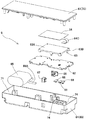
- the disassembled perspective view of the portable communication apparatus shown by FIG. Sectional drawing of the portable communication apparatus shown by FIG.
- a plurality of the detection devices 10 are arranged in the dangerous place DA by being attached to each device in the plant. Information detected by these detection devices 10 is transmitted to the network construction device 4 via the repeater 3 and transmitted to the data storage management device 5.
- the plant manager can check the information stored in the data storage management device 5 using a notebook personal computer (management terminal) (not shown).
- the number of detection devices 10 may be four or more, or may be one or two.
- the state detected by the detection device 10 includes temperature, vibration, and the like.
- the administrator recognizes the abnormality in the state, the administrator directs the worker to the detection apparatus 10 that has detected the abnormality to perform confirmation.
- an operator wirelessly holds the portable communication device 6 over the detection device 10 in order to check whether the detection device 10 is detecting an abnormality.
- Communicate when setting the detection device 10, setting information set by the portable communication device 6, worker information, work contents, and the like can be written in the detection device 10 wirelessly.
- an NFC (Near Field Communication) standard that is short-range wireless communication can be employed.
- the detection device 10 detects an abnormality, the fact is displayed on a display unit of the detection device 10 or an operation display unit described later of the portable communication device 6.
- the portable communication device 6 includes a case 61, a circuit board 62, a spacer 63, an antenna 64, a battery 65, a power switch knob 66, and an active switch knob 67.
- Reference numeral 68 denotes a diffusing member constituting the operation display unit.
- the lower case 69 has a cup shape with a recess 71, and the circuit board 62, the spacer 63, the antenna 64, and the battery 65 are accommodated in the recess 71.
- the material of the lower case 69 is made of a conductive resin mixed with a conductive material such as carbon.
- a conductive material such as carbon.
- an ABS resin or polyacetal is suitable, and in this embodiment, it is an ABS resin.
- the conductivity of the conductive resin is preferably less than 10 9 ⁇ in an environment with a relative humidity of 50 ⁇ 5% or less than 10 11 ⁇ in an environment with a relative humidity of 30 ⁇ 5%. Since the material of the lower case 69 is a conductive material, accumulation of static electricity in the lower case 69 can be suppressed.
- an operation display unit 72 for notifying the operation state is formed on the bottom of the lower case 69.
- the operation display unit 72 light from the light source 73 such as a light emitting diode mounted on the circuit board 62 can be visually recognized through the diffusion member 68.
- the diffusing member 68 is made of milky white synthetic resin capable of transmitting light, and diffuses the light from the light source 73 so that the light from the light source 73 cannot be viewed directly.
- three operation display units 72 are provided, and each operation display unit 72 includes a cylindrical body 74 constituting an illumination chamber. By providing this cylindrical body 74, each operation display unit 72 does not affect the display because the light from the light source 73 leaks to the other operation display unit 72.
- the upper case 70 constituting the case 61 has a substantially flat plate shape and closes the opening of the concave portion 71 of the lower case 69.
- the upper case 70 is a divided body facing the antenna 64, and the material of the upper case 70 is a resin having electrical insulation, and is made of a synthetic resin that does not include a conductive material such as carbon.
- a synthetic resin suitable for this embodiment is an ABS resin or polyacetal. In this embodiment, it is an ABS resin.
- the surface area of the upper case 70 is 10,000 mm 2 or less.
- the circuit board 62 is obtained by applying a predetermined wiring pattern to a hard base material made of a resin containing glass fiber, and a light source 73 and an electronic component (not shown) are mounted thereon.
- the spacer 63 is made of synthetic resin, in this embodiment ABS resin, and is used for installing the antenna 64.
- the spacer 63 has a table shape and includes a top plate portion 63A and legs 63B, and supports the antenna 64 by the top plate portion 63A.
- the spacer 63 places the antenna 64 close to the upper case 70 and maintains a certain distance from the wiring pattern of the circuit board 62 to ensure insulation.
- the antenna 64 is a flexible insulating material such as polyimide or polyethylene terephthalate.
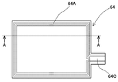
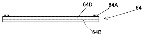
- an antenna pattern 64A is printed on one surface of a base 64D that is an insulating plate.
- the antenna pattern 64A is formed so as to double surround the vicinity of the outer periphery of the rectangular base material 64D. By setting the shape of the antenna pattern 64A, a coil can be formed on the base material 64D.
- the antenna 64 includes a connection piece 64C in a part of the base material 64D, and the connection piece 64C is connected to a connector 62A formed on the circuit board 62 to perform electrical connection.
- the antenna 64 has a magnetic sheet 64B attached to the back surface on the opposite side, where the antenna pattern 64A side of the base material 64D is the front surface.
- This magnetic sheet 64B is made of sintered ferrite, adjusted so as to have a high magnetic permeability and low loss characteristics in the communication frequency band, and has a magnetic shield function.
- the radio wave generated by the antenna 64 is reflected without passing through the magnetic sheet 64B side and reflected by the antenna pattern 64A side, so that the radio wave is not affected by the circuit board 62 on the back side of the antenna 64. Since it is transmitted to the surface side of the antenna 64 and the loss is small, the communication distance can be extended.
- the antenna pattern 64A is covered with a protective material (not shown) to protect the antenna pattern 64A.
- the battery 65 supplies power to a circuit (not shown) formed on the circuit board 62, an antenna 64, and the like.
- the battery 65 is a battery pack in which two lithium primary batteries are connected in parallel.
- 62 is connected by a connector (not shown).
- 65A in FIG. 2 is a wiring of the battery 65, a part of which is illustrated.
- the power switch knob 66 is made of synthetic resin and operates a switch element (not shown) provided on the circuit board 62. By operating the power switch knob 66, the main power source of the portable communication device 6 is turned on / off.
- the active switch knob 67 is made of synthetic resin and operates a switch element (not shown) provided on the circuit board 62. By operating this active switch knob 67, the communication function of the portable communication device 6 is turned on / off.
- the case 61 includes at least two divided bodies of the first divided body 69 and the second divided body 70. And at least a part of the divided body 70 facing the antenna 64 of one of the two divided bodies 69 and 70 is an electrically insulating resin that satisfies the explosion-proof requirements, and the other divided body 69 is a conductive resin.
- the portable communication device 6 that can be used in the dangerous place DA can be provided.
- the conductivity of the conductive resin is 10 9 ⁇ or less in an environment with a relative humidity of 50 ⁇ 5%, or 10 11 ⁇ or less in an environment with a relative humidity of 30 ⁇ 5%. Due to the antistatic effect of the resin, even if a person charged in a flammable gas atmosphere in the dangerous place DA touches, an explosion caused by static sparks can be suppressed.
- the antenna 64 has an antenna pattern 64A printed on an insulating material made of polyimide or polyethylene terephthalate.
- an insulating material made of polyimide or polyethylene terephthalate.
- the antenna 64 can be disposed close to the upper case 70, and the circuit board can be disposed. It is possible to ensure insulation by taking a certain distance from the 62 wiring patterns.
- the operation display unit 72 for notifying the operation of the portable communication device 6 the operation of the portable communication device 6 can be visually confirmed.
- the operation display unit 72 is provided in the divided body 69 made of the conductive resin, a person charged in a flammable gas atmosphere in the dangerous place DA is touched by the antistatic effect of the conductive resin. But it can suppress explosions caused by static sparks.
- the portion of the divided body 70 made of an electrically insulating resin that satisfies the explosion-proof requirements is made of a conductive resin, so that the influence on communication is suppressed and the portable type has explosion-proof properties.
- a communication device 6 can be provided.
- the case 61 is formed by dividing the lower case 69 and the upper case 70 into two parts.
- the case 61 is not limited to two parts and may be divided into three parts.
- the present invention is suitable as a portable communication device used in hazardous places such as plants and factories.
Landscapes
- Engineering & Computer Science (AREA)
- Computer Networks & Wireless Communication (AREA)
- Signal Processing (AREA)
- Microelectronics & Electronic Packaging (AREA)
- Telephone Set Structure (AREA)
- Casings For Electric Apparatus (AREA)
- Support Of Aerials (AREA)
- Transceivers (AREA)
Abstract
危険場所で使用可能な携帯型通信装置を提供する。 アンテナ64と、このアンテナ64を収納するケース61と、を備えた携帯型通信装置6において、ケース61は、第1分割体である下ケース69及び第2分割体である上ケース70の少なくとも2つの分割体からなり、2つの分割体のどちらか一方のアンテナ64と対向する分割体70の少なくとも一部を防爆要件を満たした電気絶縁性の樹脂とし、他方の分割体69を導電性樹脂としたものである。
Description
本発明は、携帯型通信装置に関し、例えば、プラントや工場などの防爆が必要な場所で使用可能な携帯型通信装置に関する。
従来、携帯型通信装置は、機器状態収集システムの一部を構成するものであった。このような携帯型通信装置に関する従来技術として、特許文献1に開示されるものがある。
従来の技術に示されるような携帯型通信装置は、プラントや工場などの危険な場所において使用される事が想定されることが必要である。危険場所とは、プラントや工場などにおいて、可燃性ガスが空気と混合して爆発下限界以上の危険雰囲気を生成するおそれのある場所をいう。危険場所での使用が想定される通信装置は、本質安全防爆要件(JIS C60079)に適合させる必要がある。
そこで本発明の目的は、前述の課題に着目し、危険場所で使用可能な携帯型通信装置を提供することにある。
本発明の携帯型通信装置は、アンテナと、このアンテナを収納するケースと、を備えた携帯型通信装置において、前記ケースは、第1分割体及び第2分割体の少なくとも2つの分割体からなり、前記2つの分割体のどちらか一方の前記アンテナと対向する分割体の少なくとも一部を防爆要件を満たした電気絶縁性の樹脂とし、他方の分割体を導電性樹脂としたものである。
また、前記防爆要件を満たした電気絶縁性の樹脂からなる前記分割体の前記アンテナと対向しない部分を導電性樹脂としたものである。
また、前記導電性樹脂の導電率は、相対湿度50±5%の環境下で109Ω以下、または、相対湿度30±5%の環境下で1011Ω以下である。
また、前記アンテナは、ポリイミドやポリエチレンテレフタレートからなる絶縁材にアンテナパターンが印刷されたものであり、前記絶縁材の裏面に磁性シートを設けたものである。
また、前記アンテナと接続する回路基板を備え、前記アンテナと前記回路基板との間にスペーサを設けたものである。
また、前記携帯型通信装置の動作を報知する動作表示部を設けたものである。
また、前記動作表示部を前記導電性樹脂からなる分割体に設けたものである。
本発明は、危険場所で使用可能な携帯型通信装置を提供することができる。
本発明の実施形態を添付図に基づいて以下に説明する。
図1を参照する。図1には、石油化学系のプラントにおける機器状態収集システム1が示されている。石油化学系のプラントは、非常に広大である。このため、各機器の状態を検出装置10により検出し、検出された情報をデータ記憶管理装置5において管理している。
より詳細に説明する。検出装置10は、プラント内の各機器に取り付けられることにより、危険場所DA内に複数配置されている。これらの検出装置10において検出された情報は、中継器3を介してネットワーク構築装置4に送信され、データ記憶管理装置5に送信される。プラントの管理者は、データ記憶管理装置5に記憶された情報を図示しないノートパソコン(管理端末)を用いて確認することができる。
図1には3つの検出装置10が示されているが、検出装置10は、4個以上であってもよく、1または2個であってもよい。
検出装置10が検出する状態としては、温度、振動等が挙げられる。管理者は、状態の異常を認識すると、異常を検知した検出装置10まで作業者を向かわせ、確認を行わせる。
プラント内には複数の検出装置10が配置されているため、作業者は、異常を検知している検出装置10であるかを確認するために携帯型通信装置6を検出装置10にかざして無線通信を行う。また、検出装置10の設定時に、携帯型通信装置6で設定された設定情報や、作業者情報、作業内容などを検出装置10に無線により書き込み可能とすることも可能である。携帯型通信装置6と検出装置10との通信には、近距離無線通信であるNFC(Near Field Communication)規格を採用することができる。例えば、異常を検出している検出装置10である場合には、検出装置10の表示部や携帯型通信装置6の後述する動作表示部にその旨が表示される。
携帯型通信装置6は、ケース61と、回路基板62と、スペーサ63と、アンテナ64と、電池65と、電源スイッチノブ66と、アクティブスイッチノブ67とから構成されている。なお、68は、前記動作表示部を構成する拡散部材である。
ケース61は、2つの分割体で構成されており、第1分割体が下ケース69であり、第2分割体が上ケース70である。下ケース69と上ケース70は、図示しないビスなどの締結部材によって固定されている。ケース61は、回路基板62、スペーサ63、アンテナ64及び電池65を収納する。電源スイッチノブ66と、アクティブスイッチノブ67とは、ケース61に可動可能なように装着されており、拡散部材68は、ケース61に設けた開口から一部が露出するように固定されている。
下ケース69は、凹部71を備えたカップ形状であり、この凹部71内に、回路基板62、スペーサ63、アンテナ64及び電池65を収納する。下ケース69の材質は、カーボンなどの導電性を有する材料を混入した導電性樹脂からなる。導電性樹脂の合成樹脂としては、ABS樹脂やポリアセタールが好適であり、本実施形態では、ABS樹脂である。この導電性樹脂の導電率は、相対湿度50±5%の環境下で109Ω未満、または相対湿度30±5%の環境下で1011Ω未満であることが好ましい。下ケース69の材質を導電性を有する材質としたことにより、下ケース69の静電気の蓄積を抑えることができる。
また、下ケース69の底部には、動作状態を報知する動作表示部72が形成されている。動作表示部72は、回路基板62上に実装された発光ダイオードなどの光源73からの光が拡散部材68を通して視認可能となる。拡散部材68は、光が透過可能な乳白色の合成樹脂からなり、光源73の光を拡散するものであり、光源73の光を直視できないようになっている。なお、動作表示部72は、本実施形態では、3つ備えており、各動作表示部72には、照明室を構成する筒体74を備えている。この筒体74を設けたことにより、各動作表示部72は、光源73の光が、他の動作表示部72に漏れて表示に影響を与えない。
ケース61を構成する上ケース70は、ほぼ平板形状であり、下ケース69の凹部71の開口を塞ぐ。この上ケース70は、アンテナ64と対向する分割体であり、上ケース70の材質は、電気絶縁性を有する樹脂であり、カーボンなどの導電性を有する材料を含まない合成樹脂からなる。本実施形態で好適な合成樹脂は、ABS樹脂やポリアセタールである。本実施形態では、ABS樹脂である。本実施形態では、防爆要件を満たすために、上ケース70の表面積は、10000mm2以下である。
回路基板62は、ガラス繊維入り樹脂からなる硬質の基材に、所定の配線パターンが施されたものであり、光源73や図示しない電子部品などが実装されている。
スペーサ63は、合成樹脂、本実施形態ではABS樹脂からなり、アンテナ64を設置するものである。このスペーサ63は、テーブル状であり、天板部分63Aと脚部63Bとを備え、天板部分63Aでアンテナ64を支持するものである。このスペーサ63は、アンテナ64を上ケース70に近接配置するとともに、回路基板62の前記配線パターンから一定の距離を保ち、絶縁を確保するものである。
アンテナ64は、ポリイミドやポリエチレンテレフタレートなどの可撓性を有する絶縁材、本実施形態では絶縁性の板形状体の基材64Dの片面にアンテナパターン64Aが印刷形成されたものである。アンテナパターン64Aは、矩形の基材64Dの外周近傍を二重に囲むように形成したものである。上記のアンテナパターン64Aの形状とすることで、基材64D上にコイルを形成することができる。なお、アンテナ64は、基材64Dの一部に接続片64Cを備えており、この接続片64Cを回路基板62に形成したコネクタ62Aに接続し、電気的接続を行う。
アンテナ64は、基材64Dのアンテナパターン64Aを設けた側を表面とすると、反対側の裏面に磁性シート64Bが貼り付けられている。この磁性シート64Bは、焼結体フェライトからなり、通信周波数帯では透磁率が高く、損失が少ない特性となるように調整してあり、磁気シールド機能を有する。アンテナ64で発生した電波が磁性シート64B側を透過せずに反射されて、アンテナパターン64Aを設けた側に反射することによって、電波が、アンテナ64の裏面側の回路基板62の影響を受けずアンテナ64の表面側に発信され、さらに、損失が少ないことから通信距離を伸ばすことが可能となる。なお、アンテナパターン64Aは、アンテナパターン64Aを保護するために、図示しない保護材によって覆われている。
電池65は、回路基板62に形成された図示しない回路やアンテナ64などに電力を供給するものであり、本実施形態では、リチウム1次電池を2本並列に接続したバッテリーパックであり、回路基板62に図示しないコネクタにより接続される。なお、図2中の65Aは、一部を図示した電池65の配線である。
電源スイッチノブ66は、合成樹脂からなり、回路基板62に設けた図示しないスイッチ素子を操作するものである。この電源スイッチノブ66を操作することによって、携帯型通信装置6のメイン電源のオンオフを操作する。
アクティブスイッチノブ67は、合成樹脂からなり、回路基板62に設けた図示しないスイッチ素子を操作するものである。このアクティブスイッチノブ67を操作することによって、携帯型通信装置6の通信機能のオンオフを操作する。
以上の構成によって、危険場所DA内には、複数の検出装置10が配置されている。このため、作業者は、携帯型通信装置6を検出装置10にかざすことにより、検出装置10が異常を検出しているか否かを確認することができる。例えば、異常を検出している検出装置10である場合には、携帯型通信装置6の動作表示部72を点灯させる。
以上のように、アンテナ64と、このアンテナ64を収納するケース61と、を備えた携帯型通信装置6において、ケース61は、第1分割体69及び第2分割体70の少なくとも2つの分割体からなり、2つの分割体69、70のどちらか一方のアンテナ64と対向する分割体70の少なくとも一部を防爆要件を満たした電気絶縁性の樹脂とし、他方の分割体69を導電性樹脂としたことによって、危険場所DAで使用可能な携帯型通信装置6を提供することができる。
また、前記導電性樹脂の導電率は、相対湿度50±5%の環境下で109Ω以下、または、相対湿度30±5%の環境下で1011Ω以下であることによって、前記導電性樹脂の帯電防止効果により、危険場所DAでの可燃性ガス雰囲気中で帯電した人が触れた場合でも静電気による火花が原因の爆発を抑制することができる。
また、アンテナ64は、ポリイミドやポリエチレンテレフタレートからなる絶縁材にアンテナパターン64Aが印刷されたものであり、前記絶縁材の裏面に磁性シート64Bを設けたことによって、通信周波数帯での透磁率が高く、損失が少ない特性が得られることから、アンテナ64から発信される電波が、裏面側の回路基板62の影響を受けず表面側に発信され、さらに損失が少ないことから通信距離を伸ばすことが可能となる。
また、アンテナ64と接続する回路基板62を備え、アンテナ64と回路基板62との間にスペーサ63を設けたことによって、アンテナ64を上ケース70に近接させて配置することができるとともに、回路基板62の前記配線パターンから一定の距離をとり、絶縁を確保することができる。
また、携帯型通信装置6の動作を報知する動作表示部72を設けたことによって、携帯型通信装置6の動作を目視で確認することができる。
また、動作表示部72を前記導電性樹脂からなる分割体69に設けたことによって、前記導電性樹脂の帯電防止効果により、危険場所DAでの可燃性ガス雰囲気中で帯電した人が触れた場合でも静電気による火花が原因の爆発を抑制することができる。
次に、本発明の第2実施形態を説明する。
第1実施形態では、ケース61を構成する上ケース70は、電気絶縁性を有する樹脂のみで形成されていた。しかし、第1実施形態より厳しい防爆要件を満たすために、防爆要件を満たした電気絶縁性の樹脂からなる第2分割体である上ケース70のアンテナ64と対向する部分のみを防爆要件を満たすように電気絶縁性の樹脂を用い、アンテナ64と対向したい部分を導電性樹脂としてもよい。この場合、第2分割体である上ケース70は、電気絶縁性の樹脂と導電性樹脂との二種類の樹脂から構成される。この場合、電気絶縁性の樹脂と導電性樹脂との異なる材質どうしを組み合わせて一体に成形することも可能であるし、異なる材質を機械的な結合手段で結合することも可能である。
以上のように、防爆要件を満たした電気絶縁性の樹脂からなる分割体70のアンテナ64と対向しない部分を導電性樹脂としたことによって、通信への影響を抑え、かつ防爆性を有する携帯型通信装置6を提供することができる。
なお、前記実施形態では、ケース61は、下ケース69と上ケース70の二分割に形成したが、二分割に限定されるものではなく、三分割であってもよい。
また、防爆要件を満たすために、電気絶縁性の樹脂の表面積は、前記実施形態に限定されるものではなく、要求される防爆要件によって、任意に変更可能である。
本発明は、プラントや工場などの危険場所に用いられる携帯型通信装置として好適である。
1 機器状態収集システム
3 中継器
4 ネットワーク構築装置
5 データ記憶管理装置
6 携帯型通信装置
10 検出装置
61 ケース
62 回路基板
62A コネクタ
63 スペーサ
63A 天板部分
63B 脚部
64 アンテナ
64A アンテナパターン
64B 磁性シート
64C 接続片
64D 基材
65 電池
66 電源スイッチノブ
67 アクティブスイッチノブ
68 拡散部材
69 第1分割体(下ケース)
70 第2分割体(上ケース)
71 凹部
72 動作表示部
73 光源
74 筒体
DA 危険場所
3 中継器
4 ネットワーク構築装置
5 データ記憶管理装置
6 携帯型通信装置
10 検出装置
61 ケース
62 回路基板
62A コネクタ
63 スペーサ
63A 天板部分
63B 脚部
64 アンテナ
64A アンテナパターン
64B 磁性シート
64C 接続片
64D 基材
65 電池
66 電源スイッチノブ
67 アクティブスイッチノブ
68 拡散部材
69 第1分割体(下ケース)
70 第2分割体(上ケース)
71 凹部
72 動作表示部
73 光源
74 筒体
DA 危険場所
Claims (7)
- アンテナと、このアンテナを収納するケースと、を備えた携帯型通信装置において、前記ケースは、第1分割体及び第2分割体の少なくとも2つの分割体からなり、前記2つの分割体のどちらか一方の前記アンテナと対向する分割体の少なくとも一部を防爆要件を満たした電気絶縁性の樹脂とし、他方の分割体を導電性樹脂としたことを特徴とする携帯型通信装置。
- 前記防爆要件を満たした電気絶縁性の樹脂からなる前記分割体の前記アンテナと対向しない部分を導電性樹脂としたことを特徴とする請求項1に記載の携帯型通信装置。
- 前記導電性樹脂の導電率は、相対湿度50±5%の環境下で109Ω以下、または、相対湿度30±5%の環境下で1011Ω以下であることを特徴とする請求項1に記載の携帯型通信装置。
- 前記アンテナは、ポリイミドやポリエチレンテレフタレートからなる絶縁材にアンテナパターンが印刷されたものであり、前記絶縁材の裏面に磁性シートを設けたことを特徴とする請求項1に記載の携帯型通信装置。
- 前記アンテナと接続する回路基板を備え、前記アンテナと前記回路基板との間にスペーサを設けたことを特徴とする請求項1に記載の携帯型通信装置。
- 前記携帯型通信装置の動作を報知する動作表示部を設けたことを特徴とする請求項1に記載の携帯型通信装置。
- 前記動作表示部を前記導電性樹脂からなる分割体に設けたことを特徴とする請求項6に記載の携帯型通信装置。
Priority Applications (3)
| Application Number | Priority Date | Filing Date | Title |
|---|---|---|---|
| US16/340,309 US20200091587A1 (en) | 2016-10-24 | 2017-10-13 | Portable communication device |
| JP2018547560A JPWO2018079305A1 (ja) | 2016-10-24 | 2017-10-13 | 携帯型通信装置 |
| CN201780065507.7A CN109845116A (zh) | 2016-10-24 | 2017-10-13 | 便携式通信装置 |
Applications Claiming Priority (2)
| Application Number | Priority Date | Filing Date | Title |
|---|---|---|---|
| JP2016-207543 | 2016-10-24 | ||
| JP2016207543 | 2016-10-24 |
Publications (1)
| Publication Number | Publication Date |
|---|---|
| WO2018079305A1 true WO2018079305A1 (ja) | 2018-05-03 |
Family
ID=62024974
Family Applications (1)
| Application Number | Title | Priority Date | Filing Date |
|---|---|---|---|
| PCT/JP2017/037149 Ceased WO2018079305A1 (ja) | 2016-10-24 | 2017-10-13 | 携帯型通信装置 |
Country Status (4)
| Country | Link |
|---|---|
| US (1) | US20200091587A1 (ja) |
| JP (1) | JPWO2018079305A1 (ja) |
| CN (1) | CN109845116A (ja) |
| WO (1) | WO2018079305A1 (ja) |
Citations (4)
| Publication number | Priority date | Publication date | Assignee | Title |
|---|---|---|---|---|
| JPH01300624A (ja) * | 1988-05-28 | 1989-12-05 | Furukawa Electric Co Ltd:The | 高電圧導体用無線送信機付き温度センサ装置 |
| JP2012119002A (ja) * | 2012-01-13 | 2012-06-21 | Seiko Epson Corp | 非接触データ通信機能を備えた装着型電子機器、及び非接触データ通信システム |
| JP2012129779A (ja) * | 2010-12-15 | 2012-07-05 | Yokogawa Electric Corp | 耐圧防爆容器 |
| WO2014210183A2 (en) * | 2013-06-28 | 2014-12-31 | Wek Electronics Co., Ltd. | Rfid card learning apparatus and operating method thereof |
Family Cites Families (14)
| Publication number | Priority date | Publication date | Assignee | Title |
|---|---|---|---|---|
| JP2992464B2 (ja) * | 1994-11-04 | 1999-12-20 | キヤノン株式会社 | 集電電極用被覆ワイヤ、該集電電極用被覆ワイヤを用いた光起電力素子及びその製造方法 |
| JP3454959B2 (ja) * | 1995-03-15 | 2003-10-06 | 株式会社東芝 | 携帯電話装置 |
| JP4588180B2 (ja) * | 2000-08-22 | 2010-11-24 | パナソニック株式会社 | 非接触icカード読取/書込装置 |
| JP2003158415A (ja) * | 2001-11-20 | 2003-05-30 | Ntn Corp | 無線通信機能付き機器 |
| WO2005054010A1 (ja) * | 2003-12-05 | 2005-06-16 | Harada Industry Co., Ltd. | 自動車アンテナ用増幅器ケース |
| CN101233533B (zh) * | 2005-08-03 | 2011-02-16 | 松下电器产业株式会社 | 天线内置型存储媒介物 |
| JP4881247B2 (ja) * | 2007-07-13 | 2012-02-22 | 株式会社東芝 | 電子機器及びその製造方法 |
| JP5424341B2 (ja) * | 2010-05-18 | 2014-02-26 | Necカシオモバイルコミュニケーションズ株式会社 | 携帯通信端末 |
| US11182661B2 (en) * | 2011-01-06 | 2021-11-23 | Maplebear Inc. | Reader network system for presence management in a physical retail environment |
| JP5482915B2 (ja) * | 2011-02-10 | 2014-05-07 | 株式会社村田製作所 | メタマテリアル、電気装置、および、メタマテリアルを備えた電気装置 |
| JP5291829B1 (ja) * | 2012-02-28 | 2013-09-18 | 株式会社Maruwa | 両面接着スペーサ、並びに、アンテナモジュール及びその製造方法 |
| JP5907479B2 (ja) * | 2013-03-22 | 2016-04-26 | カシオ計算機株式会社 | アンテナ装置及び電子機器 |
| WO2015016353A1 (ja) * | 2013-08-02 | 2015-02-05 | 株式会社村田製作所 | アンテナ装置及び通信端末機器 |
| JP6467943B2 (ja) * | 2015-01-27 | 2019-02-13 | 日本精機株式会社 | プラント機器状態収集システム |
-
2017
- 2017-10-13 US US16/340,309 patent/US20200091587A1/en not_active Abandoned
- 2017-10-13 WO PCT/JP2017/037149 patent/WO2018079305A1/ja not_active Ceased
- 2017-10-13 JP JP2018547560A patent/JPWO2018079305A1/ja active Pending
- 2017-10-13 CN CN201780065507.7A patent/CN109845116A/zh active Pending
Patent Citations (4)
| Publication number | Priority date | Publication date | Assignee | Title |
|---|---|---|---|---|
| JPH01300624A (ja) * | 1988-05-28 | 1989-12-05 | Furukawa Electric Co Ltd:The | 高電圧導体用無線送信機付き温度センサ装置 |
| JP2012129779A (ja) * | 2010-12-15 | 2012-07-05 | Yokogawa Electric Corp | 耐圧防爆容器 |
| JP2012119002A (ja) * | 2012-01-13 | 2012-06-21 | Seiko Epson Corp | 非接触データ通信機能を備えた装着型電子機器、及び非接触データ通信システム |
| WO2014210183A2 (en) * | 2013-06-28 | 2014-12-31 | Wek Electronics Co., Ltd. | Rfid card learning apparatus and operating method thereof |
Also Published As
| Publication number | Publication date |
|---|---|
| US20200091587A1 (en) | 2020-03-19 |
| CN109845116A (zh) | 2019-06-04 |
| JPWO2018079305A1 (ja) | 2019-09-12 |
Similar Documents
| Publication | Publication Date | Title |
|---|---|---|
| RU2204871C2 (ru) | Защита от электростатического разряда в переносном устройстве связи | |
| CA2726613C (en) | Improved form factor and electromagnetic interference protection for process device wireless adapters | |
| KR20200017115A (ko) | 쉴드 캔의 개구부를 덮는 도전성 플레이트와 연결된 차폐 부재를 포함하는 전자 장치 | |
| JP2024045514A (ja) | 電池パック | |
| KR102880919B1 (ko) | Fpcb 구조체를 포함하는 전자 장치 | |
| JPWO2015163295A1 (ja) | アンテナ装置および電子機器 | |
| AU2017239629B2 (en) | System and method for i-safe mobile devices | |
| JPWO2017130762A1 (ja) | 通信装置 | |
| JP5795846B2 (ja) | 置き台及びテーブル | |
| JP7008259B2 (ja) | 携帯型通信装置 | |
| CN112950911B (zh) | 自发电型漏水检测器 | |
| WO2018021005A1 (ja) | 通信装置 | |
| JPWO2018079305A1 (ja) | 携帯型通信装置 | |
| JP2005276045A (ja) | 防爆型端末装置 | |
| KR20190088192A (ko) | 안테나의 위상을 스윕하기 위한 전자 장치 | |
| US20120222946A1 (en) | Key Module, Keyboard and Electric Device | |
| US11475267B2 (en) | Booster antenna and portable terminal stand | |
| JP6924375B2 (ja) | 通信装置 | |
| KR102574774B1 (ko) | 안테나 및 그것을 포함하는 전자 장치 | |
| CN213425171U (zh) | 一种天线装置及手持终端 | |
| CN216292043U (zh) | 功能扩充组件 | |
| JP4838050B2 (ja) | 無線lan防爆型中継器、防爆型スイッチングハブ、防爆型無線通信手段、防爆型無線通信手段付きスイッチングハブ及び危険地区における通信システム | |
| JP2016086227A (ja) | 遠隔操作装置 | |
| US12119547B2 (en) | High reliability portable device | |
| JP6818238B2 (ja) | 通信装置 |
Legal Events
| Date | Code | Title | Description |
|---|---|---|---|
| 121 | Ep: the epo has been informed by wipo that ep was designated in this application |
Ref document number: 17863919 Country of ref document: EP Kind code of ref document: A1 |
|
| ENP | Entry into the national phase |
Ref document number: 2018547560 Country of ref document: JP Kind code of ref document: A |
|
| NENP | Non-entry into the national phase |
Ref country code: DE |
|
| 122 | Ep: pct application non-entry in european phase |
Ref document number: 17863919 Country of ref document: EP Kind code of ref document: A1 |