WO2018079229A1 - Coated cutting tool - Google Patents
Coated cutting tool Download PDFInfo
- Publication number
- WO2018079229A1 WO2018079229A1 PCT/JP2017/036421 JP2017036421W WO2018079229A1 WO 2018079229 A1 WO2018079229 A1 WO 2018079229A1 JP 2017036421 W JP2017036421 W JP 2017036421W WO 2018079229 A1 WO2018079229 A1 WO 2018079229A1
- Authority
- WO
- WIPO (PCT)
- Prior art keywords
- layer
- aluminum oxide
- cutting tool
- coated cutting
- type aluminum
- Prior art date
Links
Classifications
-
- B—PERFORMING OPERATIONS; TRANSPORTING
- B23—MACHINE TOOLS; METAL-WORKING NOT OTHERWISE PROVIDED FOR
- B23B—TURNING; BORING
- B23B27/00—Tools for turning or boring machines; Tools of a similar kind in general; Accessories therefor
- B23B27/14—Cutting tools of which the bits or tips or cutting inserts are of special material
- B23B27/148—Composition of the cutting inserts
-
- C—CHEMISTRY; METALLURGY
- C23—COATING METALLIC MATERIAL; COATING MATERIAL WITH METALLIC MATERIAL; CHEMICAL SURFACE TREATMENT; DIFFUSION TREATMENT OF METALLIC MATERIAL; COATING BY VACUUM EVAPORATION, BY SPUTTERING, BY ION IMPLANTATION OR BY CHEMICAL VAPOUR DEPOSITION, IN GENERAL; INHIBITING CORROSION OF METALLIC MATERIAL OR INCRUSTATION IN GENERAL
- C23C—COATING METALLIC MATERIAL; COATING MATERIAL WITH METALLIC MATERIAL; SURFACE TREATMENT OF METALLIC MATERIAL BY DIFFUSION INTO THE SURFACE, BY CHEMICAL CONVERSION OR SUBSTITUTION; COATING BY VACUUM EVAPORATION, BY SPUTTERING, BY ION IMPLANTATION OR BY CHEMICAL VAPOUR DEPOSITION, IN GENERAL
- C23C28/00—Coating for obtaining at least two superposed coatings either by methods not provided for in a single one of groups C23C2/00 - C23C26/00 or by combinations of methods provided for in subclasses C23C and C25C or C25D
- C23C28/04—Coating for obtaining at least two superposed coatings either by methods not provided for in a single one of groups C23C2/00 - C23C26/00 or by combinations of methods provided for in subclasses C23C and C25C or C25D only coatings of inorganic non-metallic material
-
- B—PERFORMING OPERATIONS; TRANSPORTING
- B23—MACHINE TOOLS; METAL-WORKING NOT OTHERWISE PROVIDED FOR
- B23B—TURNING; BORING
- B23B27/00—Tools for turning or boring machines; Tools of a similar kind in general; Accessories therefor
- B23B27/14—Cutting tools of which the bits or tips or cutting inserts are of special material
-
- B—PERFORMING OPERATIONS; TRANSPORTING
- B23—MACHINE TOOLS; METAL-WORKING NOT OTHERWISE PROVIDED FOR
- B23B—TURNING; BORING
- B23B51/00—Tools for drilling machines
-
- B—PERFORMING OPERATIONS; TRANSPORTING
- B23—MACHINE TOOLS; METAL-WORKING NOT OTHERWISE PROVIDED FOR
- B23C—MILLING
- B23C5/00—Milling-cutters
- B23C5/16—Milling-cutters characterised by physical features other than shape
-
- B—PERFORMING OPERATIONS; TRANSPORTING
- B23—MACHINE TOOLS; METAL-WORKING NOT OTHERWISE PROVIDED FOR
- B23C—MILLING
- B23C5/00—Milling-cutters
- B23C5/16—Milling-cutters characterised by physical features other than shape
- B23C5/20—Milling-cutters characterised by physical features other than shape with removable cutter bits or teeth or cutting inserts
-
- C—CHEMISTRY; METALLURGY
- C23—COATING METALLIC MATERIAL; COATING MATERIAL WITH METALLIC MATERIAL; CHEMICAL SURFACE TREATMENT; DIFFUSION TREATMENT OF METALLIC MATERIAL; COATING BY VACUUM EVAPORATION, BY SPUTTERING, BY ION IMPLANTATION OR BY CHEMICAL VAPOUR DEPOSITION, IN GENERAL; INHIBITING CORROSION OF METALLIC MATERIAL OR INCRUSTATION IN GENERAL
- C23C—COATING METALLIC MATERIAL; COATING MATERIAL WITH METALLIC MATERIAL; SURFACE TREATMENT OF METALLIC MATERIAL BY DIFFUSION INTO THE SURFACE, BY CHEMICAL CONVERSION OR SUBSTITUTION; COATING BY VACUUM EVAPORATION, BY SPUTTERING, BY ION IMPLANTATION OR BY CHEMICAL VAPOUR DEPOSITION, IN GENERAL
- C23C16/00—Chemical coating by decomposition of gaseous compounds, without leaving reaction products of surface material in the coating, i.e. chemical vapour deposition [CVD] processes
- C23C16/22—Chemical coating by decomposition of gaseous compounds, without leaving reaction products of surface material in the coating, i.e. chemical vapour deposition [CVD] processes characterised by the deposition of inorganic material, other than metallic material
- C23C16/30—Deposition of compounds, mixtures or solid solutions, e.g. borides, carbides, nitrides
- C23C16/40—Oxides
- C23C16/403—Oxides of aluminium, magnesium or beryllium
-
- C—CHEMISTRY; METALLURGY
- C23—COATING METALLIC MATERIAL; COATING MATERIAL WITH METALLIC MATERIAL; CHEMICAL SURFACE TREATMENT; DIFFUSION TREATMENT OF METALLIC MATERIAL; COATING BY VACUUM EVAPORATION, BY SPUTTERING, BY ION IMPLANTATION OR BY CHEMICAL VAPOUR DEPOSITION, IN GENERAL; INHIBITING CORROSION OF METALLIC MATERIAL OR INCRUSTATION IN GENERAL
- C23C—COATING METALLIC MATERIAL; COATING MATERIAL WITH METALLIC MATERIAL; SURFACE TREATMENT OF METALLIC MATERIAL BY DIFFUSION INTO THE SURFACE, BY CHEMICAL CONVERSION OR SUBSTITUTION; COATING BY VACUUM EVAPORATION, BY SPUTTERING, BY ION IMPLANTATION OR BY CHEMICAL VAPOUR DEPOSITION, IN GENERAL
- C23C28/00—Coating for obtaining at least two superposed coatings either by methods not provided for in a single one of groups C23C2/00 - C23C26/00 or by combinations of methods provided for in subclasses C23C and C25C or C25D
- C23C28/04—Coating for obtaining at least two superposed coatings either by methods not provided for in a single one of groups C23C2/00 - C23C26/00 or by combinations of methods provided for in subclasses C23C and C25C or C25D only coatings of inorganic non-metallic material
- C23C28/042—Coating for obtaining at least two superposed coatings either by methods not provided for in a single one of groups C23C2/00 - C23C26/00 or by combinations of methods provided for in subclasses C23C and C25C or C25D only coatings of inorganic non-metallic material including a refractory ceramic layer, e.g. refractory metal oxides, ZrO2, rare earth oxides
-
- C—CHEMISTRY; METALLURGY
- C23—COATING METALLIC MATERIAL; COATING MATERIAL WITH METALLIC MATERIAL; CHEMICAL SURFACE TREATMENT; DIFFUSION TREATMENT OF METALLIC MATERIAL; COATING BY VACUUM EVAPORATION, BY SPUTTERING, BY ION IMPLANTATION OR BY CHEMICAL VAPOUR DEPOSITION, IN GENERAL; INHIBITING CORROSION OF METALLIC MATERIAL OR INCRUSTATION IN GENERAL
- C23C—COATING METALLIC MATERIAL; COATING MATERIAL WITH METALLIC MATERIAL; SURFACE TREATMENT OF METALLIC MATERIAL BY DIFFUSION INTO THE SURFACE, BY CHEMICAL CONVERSION OR SUBSTITUTION; COATING BY VACUUM EVAPORATION, BY SPUTTERING, BY ION IMPLANTATION OR BY CHEMICAL VAPOUR DEPOSITION, IN GENERAL
- C23C28/00—Coating for obtaining at least two superposed coatings either by methods not provided for in a single one of groups C23C2/00 - C23C26/00 or by combinations of methods provided for in subclasses C23C and C25C or C25D
- C23C28/04—Coating for obtaining at least two superposed coatings either by methods not provided for in a single one of groups C23C2/00 - C23C26/00 or by combinations of methods provided for in subclasses C23C and C25C or C25D only coatings of inorganic non-metallic material
- C23C28/044—Coating for obtaining at least two superposed coatings either by methods not provided for in a single one of groups C23C2/00 - C23C26/00 or by combinations of methods provided for in subclasses C23C and C25C or C25D only coatings of inorganic non-metallic material coatings specially adapted for cutting tools or wear applications
-
- C—CHEMISTRY; METALLURGY
- C23—COATING METALLIC MATERIAL; COATING MATERIAL WITH METALLIC MATERIAL; CHEMICAL SURFACE TREATMENT; DIFFUSION TREATMENT OF METALLIC MATERIAL; COATING BY VACUUM EVAPORATION, BY SPUTTERING, BY ION IMPLANTATION OR BY CHEMICAL VAPOUR DEPOSITION, IN GENERAL; INHIBITING CORROSION OF METALLIC MATERIAL OR INCRUSTATION IN GENERAL
- C23C—COATING METALLIC MATERIAL; COATING MATERIAL WITH METALLIC MATERIAL; SURFACE TREATMENT OF METALLIC MATERIAL BY DIFFUSION INTO THE SURFACE, BY CHEMICAL CONVERSION OR SUBSTITUTION; COATING BY VACUUM EVAPORATION, BY SPUTTERING, BY ION IMPLANTATION OR BY CHEMICAL VAPOUR DEPOSITION, IN GENERAL
- C23C28/00—Coating for obtaining at least two superposed coatings either by methods not provided for in a single one of groups C23C2/00 - C23C26/00 or by combinations of methods provided for in subclasses C23C and C25C or C25D
- C23C28/30—Coatings combining at least one metallic layer and at least one inorganic non-metallic layer
- C23C28/34—Coatings combining at least one metallic layer and at least one inorganic non-metallic layer including at least one inorganic non-metallic material layer, e.g. metal carbide, nitride, boride, silicide layer and their mixtures, enamels, phosphates and sulphates
- C23C28/345—Coatings combining at least one metallic layer and at least one inorganic non-metallic layer including at least one inorganic non-metallic material layer, e.g. metal carbide, nitride, boride, silicide layer and their mixtures, enamels, phosphates and sulphates with at least one oxide layer
-
- C—CHEMISTRY; METALLURGY
- C23—COATING METALLIC MATERIAL; COATING MATERIAL WITH METALLIC MATERIAL; CHEMICAL SURFACE TREATMENT; DIFFUSION TREATMENT OF METALLIC MATERIAL; COATING BY VACUUM EVAPORATION, BY SPUTTERING, BY ION IMPLANTATION OR BY CHEMICAL VAPOUR DEPOSITION, IN GENERAL; INHIBITING CORROSION OF METALLIC MATERIAL OR INCRUSTATION IN GENERAL
- C23C—COATING METALLIC MATERIAL; COATING MATERIAL WITH METALLIC MATERIAL; SURFACE TREATMENT OF METALLIC MATERIAL BY DIFFUSION INTO THE SURFACE, BY CHEMICAL CONVERSION OR SUBSTITUTION; COATING BY VACUUM EVAPORATION, BY SPUTTERING, BY ION IMPLANTATION OR BY CHEMICAL VAPOUR DEPOSITION, IN GENERAL
- C23C30/00—Coating with metallic material characterised only by the composition of the metallic material, i.e. not characterised by the coating process
- C23C30/005—Coating with metallic material characterised only by the composition of the metallic material, i.e. not characterised by the coating process on hard metal substrates
-
- B—PERFORMING OPERATIONS; TRANSPORTING
- B23—MACHINE TOOLS; METAL-WORKING NOT OTHERWISE PROVIDED FOR
- B23B—TURNING; BORING
- B23B2222/00—Materials of tools or workpieces composed of metals, alloys or metal matrices
- B23B2222/16—Cermet
-
- B—PERFORMING OPERATIONS; TRANSPORTING
- B23—MACHINE TOOLS; METAL-WORKING NOT OTHERWISE PROVIDED FOR
- B23B—TURNING; BORING
- B23B2222/00—Materials of tools or workpieces composed of metals, alloys or metal matrices
- B23B2222/28—Details of hard metal, i.e. cemented carbide
-
- B—PERFORMING OPERATIONS; TRANSPORTING
- B23—MACHINE TOOLS; METAL-WORKING NOT OTHERWISE PROVIDED FOR
- B23B—TURNING; BORING
- B23B2226/00—Materials of tools or workpieces not comprising a metal
- B23B2226/12—Boron nitride
- B23B2226/125—Boron nitride cubic [CBN]
-
- B—PERFORMING OPERATIONS; TRANSPORTING
- B23—MACHINE TOOLS; METAL-WORKING NOT OTHERWISE PROVIDED FOR
- B23B—TURNING; BORING
- B23B2226/00—Materials of tools or workpieces not comprising a metal
- B23B2226/18—Ceramic
-
- B—PERFORMING OPERATIONS; TRANSPORTING
- B23—MACHINE TOOLS; METAL-WORKING NOT OTHERWISE PROVIDED FOR
- B23B—TURNING; BORING
- B23B2228/00—Properties of materials of tools or workpieces, materials of tools or workpieces applied in a specific manner
- B23B2228/08—Properties of materials of tools or workpieces, materials of tools or workpieces applied in a specific manner applied by physical vapour deposition [PVD]
-
- B—PERFORMING OPERATIONS; TRANSPORTING
- B23—MACHINE TOOLS; METAL-WORKING NOT OTHERWISE PROVIDED FOR
- B23B—TURNING; BORING
- B23B2228/00—Properties of materials of tools or workpieces, materials of tools or workpieces applied in a specific manner
- B23B2228/10—Coatings
- B23B2228/105—Coatings with specified thickness
Definitions
- the present invention relates to a coated cutting tool.
- a coated cutting tool formed by vapor-depositing a coating layer with a total film thickness of 3 to 20 ⁇ m by chemical vapor deposition on the surface of a substrate made of cemented carbide has been used for cutting of steel or cast iron.
- the coating layer for example, a single layer selected from the group consisting of Ti carbide, nitride, carbonitride, carbonate and carbonitride, and aluminum oxide, or a coating layer composed of two or more layers It is.
- a hard coating layer is included on the surface of a substrate, at least one of the hard coating layers is an ⁇ -Al 2 O 3 layer, and the texture coefficient TC (0012) of the ⁇ -Al 2 O 3 layer is A cutting insert in which the residual stress of the ⁇ -Al 2 O 3 layer is 5 to 300 MPa and the residual stress of the base material is ⁇ 2000 MPa to ⁇ 400 MPa is disclosed.
- Patent Document 1 has excellent wear resistance, but lacks fracture resistance under cutting conditions in which a large load acts on the coated cutting tool. Improvement in service life is required.
- the present invention has been made to solve this problem, and an object thereof is to provide a coated cutting tool having excellent wear resistance and fracture resistance and having a long tool life.
- the present inventors have conducted research on extending the tool life of the coated cutting tool.
- the following configuration including optimizing the crystal orientation of the ⁇ -type aluminum oxide layer is adopted, the fracture resistance is improved.
- the inventors have obtained the knowledge that the tool life can be extended, and have completed the present invention.
- the gist of the present invention is as follows.
- a coated cutting tool comprising a substrate and a coating layer formed on the surface of the substrate, The coating layer includes at least one ⁇ -type aluminum oxide layer;
- the texture coefficient TC (0, 0, 12) of the (0, 0, 12) plane represented by the following formula (1) is 4.0 or more and 8.4 or less.
- a coated cutting tool in which the texture coefficient TC (1, 2, 11) of the (1, 2, 11) plane represented by the formula (2) is 0.5 or more and 3.0 or less.
- I (h, k, l) represents the peak intensity of the (h, k, l) plane in the X-ray diffraction of the ⁇ -type aluminum oxide layer
- I 0 ( h, k, l) represents the standard diffraction intensity of the (h, k, l) plane in ⁇ -type aluminum oxide JCPDS card number 10-0173
- (h, k, l) represents (0, 1, 2).
- a Ti compound in which the coating layer is composed of a Ti compound of Ti and at least one element selected from the group consisting of C, N, O and B between the base material and the ⁇ -type aluminum oxide layer A coated cutting tool according to any one of [1] to [6], comprising a layer.
- the Ti compound layer includes at least one TiCN layer, and (3, 1) in the X-ray diffraction of the TiCN layer with respect to the peak intensity I 220 of the (2, 2, 0) plane in the X-ray diffraction of the TiCN layer. 1) The coated cutting tool according to [7], wherein the ratio I 311 / I 220 of the peak bending strength I 311 of the surface is 1.5 or more and 20.0 or less.
- the wear resistance and fracture resistance can be improved, and as a result, a coated cutting tool having a long tool life can be provided.
- the present embodiment a mode for carrying out the present invention (hereinafter simply referred to as “the present embodiment”) will be described in detail, but the present invention is not limited to the present embodiment described below.
- the present invention can be variously modified without departing from the gist thereof.
- the coated cutting tool of this embodiment is a coated cutting tool comprising a base material and a coating layer formed on the surface of the base material, the coating layer including at least one ⁇ -type aluminum oxide layer,
- the texture coefficient TC (0, 0, 12) of the (0, 0, 12) plane represented by the following formula (1) is 4.0 or more and 8.4 or less.
- the texture coefficient TC (1, 2, 11) of the (1, 2, 11) plane represented by 2) is 0.5 or more and 3.0 or less.
- I (h, k, l) represents the peak intensity of the (h, k, l) plane in the X-ray diffraction of the ⁇ -type aluminum oxide layer
- I 0 (H, k, l) indicates the standard diffraction intensity of the (h, k, l) plane in JCPDS card number 10-0173 of ⁇ -type aluminum oxide
- (h, k, l) is (0, 1, 2), (1, 0, 4), (1, 1, 0), (1, 1, 3), (1, 1, 6), (2, 1, 4), (3, 0, 0) , (0, 0, 12) and (1, 2, 11).
- the coated cutting tool of the present embodiment can improve wear resistance and fracture resistance by providing the above-described configuration, and as a result, the tool life can be extended.
- the factors that improve the wear resistance and fracture resistance of the coated cutting tool of the present embodiment are considered as follows. However, the factors are not limited to the following. That is, first, in the ⁇ -type aluminum oxide layer of this embodiment, the texture coefficient TC (0, 0, 12) of the (0, 0, 12) plane represented by the above formula (1) is 4.0 or more and 8. By being 4 or less, it indicates that the ratio of the peak intensity I (0, 0, 12) on the (0, 0, 12) plane is high, and the (0, 0, 12) plane is preferentially oriented. It shows that.
- the texture coefficient TC (1, 2, 11) of the (1, 2, 11) plane represented by the above formula (2) is 0.5 or more and 3.0 or less. This indicates that the ratio of the peak intensity I (1,2,11) of the (1,2,11) plane is high, and the (1,2,11) plane is the (0,0,12) plane. It shows that it is oriented. As a result, the occurrence of cracks can be suppressed, and in particular, the occurrence of cracks can be suppressed even under high temperature cutting conditions, resulting in improved fracture resistance.
- the sum of those texture coefficients TC (0, 0, 12) and TC (1, 2, 11) is 4.5 or more, which is equal to or more than the sum of the texture coefficients of other crystal planes, Since the (0, 0, 12) plane and the (1, 2, 11) plane are preferentially oriented over other crystal planes, the above-described improvement in wear resistance and fracture resistance must be achieved reliably. Can do.
- the coated cutting tool of this embodiment has a base material and a coating layer provided on the base material.
- Specific examples of the coated cutting tool include milling or turning cutting edge exchangeable cutting inserts, drills, and end mills.
- the substrate in the present embodiment is not particularly limited as long as it can be used as a substrate for a coated cutting tool.
- the base material include cemented carbide, cermet, ceramics, cubic boron nitride sintered body, diamond sintered body, and high-speed steel.
- the base material is any one of cemented carbide, cermet, ceramics, and cubic boron nitride sintered body, since it is further excellent in wear resistance and fracture resistance. More preferably, it is an alloy.
- the base material may have a modified surface.
- a de- ⁇ layer may be formed on the surface.
- a base material consists of cermets
- the hardened layer may be formed in the surface. Even if the surface of the substrate is modified as described above, the effects of the present invention are exhibited.
- the average thickness of the coating layer in the present embodiment is preferably 3.0 ⁇ m or more and 30.0 ⁇ m or less.
- the average thickness of the coating layer is more preferably 3.0 ⁇ m or more and 20.0 ⁇ m or less, and further preferably 5.0 ⁇ m or more and 20.0 ⁇ m or less.
- the average thickness of each layer in the coated cutting tool of the present embodiment is obtained by measuring the thickness of each layer and the entire thickness of the coating layer from three or more cross sections and calculating the average value thereof. Can do.
- the coating layer in the present embodiment includes at least one ⁇ -type aluminum oxide layer.
- the ⁇ -type aluminum oxide layer has a texture coefficient TC (0, 0, 12) of the (0, 0, 12) plane represented by the formula (1) of 4.0 or more and 8.4 or less.
- the texture coefficient TC (0, 0, 12) in the ⁇ -type aluminum oxide layer is preferably 5.0 or more and 8.2 or less, and more preferably 5.5 or more and 8.1 or less. preferable.
- the ⁇ -type aluminum oxide layer has a texture coefficient TC (1, 2, 11) of (1, 2, 11) plane represented by the formula (2) of 0.5 or more and 3.0 or less.
- the texture coefficient TC (1, 2, 11) increases, the ratio of the peak intensity I (1, 2, 11) on the (1, 2, 11) plane increases, and as a result, the occurrence of cracks can be suppressed. Because it can, it is excellent in fracture resistance.
- the texture coefficient TC (1, 2, 11) in the ⁇ -type aluminum oxide layer is preferably 1.0 or more and 2.5 or less.
- the average thickness of the ⁇ -type aluminum oxide layer of the present embodiment is preferably 1.0 ⁇ m or more and 15.0 ⁇ m or less.
- the average thickness of the ⁇ -type aluminum oxide layer is 1.0 ⁇ m or more, the crater wear resistance on the rake face of the coated cutting tool tends to be further improved.
- the average thickness of the ⁇ -type aluminum oxide layer is 15.0 ⁇ m or less, peeling is further suppressed and the fracture resistance tends to be further improved.
- the average thickness of the ⁇ -type aluminum oxide layer is more preferably 3.0 ⁇ m or more and 12.0 ⁇ m or less.
- the residual stress value on the (1, 1, 6) plane of the ⁇ -type aluminum oxide layer is preferably at least partly ⁇ 300 MPa or more and 300 MPa or less.
- the residual stress value is ⁇ 300 MPa or more, the progress of wear starting from the dropping of particles of the ⁇ -type aluminum oxide layer can be suppressed, so that the wear resistance tends to be improved.
- the crack generation in the ⁇ -type aluminum oxide layer can be further suppressed when the residual stress value is 300 MPa or less, the fracture resistance of the coated cutting tool tends to be further improved.
- the residual stress value on the (1, 1, 6) plane of the ⁇ -type aluminum oxide layer is more preferably ⁇ 300 MPa or more and 100 MPa or less.
- “at least in part” means that the entire ⁇ -type aluminum oxide layer does not need to satisfy the range of the residual stress value in the (1, 1, 6) plane of the ⁇ -type aluminum oxide layer, such as a rake face. It is shown that the range of the residual stress value should be satisfied in the (1, 1, 6) plane of the ⁇ -type aluminum oxide layer in the specific region.
- the residual stress value of the ⁇ -type aluminum oxide layer can be measured by the sin 2 ⁇ method using an X-ray stress measurement apparatus.
- the residual stress at any three points in the coating layer is measured by the sin 2 ⁇ method, and the average value of the residual stress at these three points is obtained.
- Arbitrary three points in the coating layer to be measured are selected, for example, to be separated from each other by 0.1 mm or more.
- the (1, 1, 6) plane of the ⁇ -type aluminum oxide layer to be measured is selected. Specifically, the sample on which the ⁇ -type aluminum oxide layer is formed is analyzed by an X-ray diffractometer. Then, a change in the diffraction angle of the (1, 1, 6) plane when the angle ⁇ formed by the sample plane normal and the lattice plane normal is changed is examined.
- the average particle diameter of the ⁇ -type aluminum oxide layer is preferably 0.1 ⁇ m or more and 3.0 ⁇ m or less.
- the average particle size of the ⁇ -type aluminum oxide layer is more preferably 0.3 ⁇ m or more and 1.5 ⁇ m or less.
- the average particle diameter of the ⁇ -type aluminum oxide layer is determined by the electron backscatter diffraction attached to the commercially available field emission scanning electron microscope (FE-SEM) or transmission electron microscope (TEM). It can be determined using an imaging device (EBSD). Specific examples are shown below.
- the coated cutting tool is mirror-polished in a direction parallel or substantially parallel to the surface of the substrate to expose the cross-sectional structure of the ⁇ -type aluminum oxide layer. Examples of the method for exposing the cross-sectional structure of the ⁇ -type aluminum oxide layer include a method of polishing using diamond paste or colloidal silica, ion milling, and the like.
- a sample in which the cross-sectional structure of the ⁇ -type aluminum oxide layer is exposed is set in an FE-SEM, and the sample is irradiated with an electron beam at an incident angle of 70 degrees under conditions of an acceleration voltage of 15 kV and an irradiation current of 0.5 nA.
- a measurement range of 30 ⁇ m ⁇ 50 ⁇ m is measured with an EBSD setting of a 0.1 ⁇ m step size.
- the particle is a region surrounded by a tissue boundary having an orientation difference of 5 ° or more.
- the diameter of a circle having an area equal to the area of the particle is defined as the particle diameter of the particle.
- Image analysis software may be used when obtaining the particle size from the cross-sectional structure of the ⁇ -type aluminum oxide layer.
- the particle diameters of the ⁇ -type aluminum oxide layer in the range of 30 ⁇ m ⁇ 50 ⁇ m are obtained, and the average value is taken as the average particle diameter of the ⁇ -type aluminum oxide layer.
- Ti composed of a Ti compound of Ti and at least one element selected from the group consisting of C, N, O, and B between the base material and the ⁇ -type aluminum oxide layer. It is preferable to provide a compound layer because the wear resistance and adhesion are further improved. From the same viewpoint, the Ti compound layer is preferably made of a Ti compound of Ti and at least one element selected from the group consisting of C, N, and O.
- the Ti compound layer of the present embodiment includes at least one TiCN layer because the wear resistance is further improved.
- the peak intensity of the (2, 2, 0) plane in the X-ray diffraction of the TiCN layer is I 220 and the peak intensity of the (3, 1, 1) plane in the X-ray diffraction of the TiCN layer is I 311, it corresponds to I 220 .
- the ratio I 311 / I 220 of the I 311 is preferably 1.5 or more 20.0 or less. When the ratio I 311 / I 220 in the TiCN layer is 1.5 or more and 20.0 or less, the adhesion from the TiCN layer to the ⁇ -type aluminum oxide layer tends to be further improved.
- the ratio I 311 / I 220 in the TiCN layer is 1.5 or more and 20.0 or less, the value of the texture coefficient TC (1, 2, 11) in the ⁇ -type aluminum oxide layer tends to be further increased. ,preferable. From the same viewpoint, the ratio I 311 / I 220 in the TiCN layer is more preferably 2.5 or more and 20.0 or less.
- the peak intensity of each crystal plane of the ⁇ -type aluminum oxide layer and the TiCN layer can be measured by using a commercially available X-ray diffractometer.
- X-ray diffractometer For example, an X-ray diffraction measurement of a 2 ⁇ / ⁇ concentrated optical system using Cu—K ⁇ rays using a Rigaku X-ray diffractometer RINT TTRIII, output: 50 kV, 250 mA, incident side solar slit: 5 ° Divergence longitudinal slit: 2/3 °, divergence longitudinal restriction slit: 5 mm, scattering slit: 2/3 °, light receiving side solar slit: 5 °, light receiving slit: 0.3 mm, BENT monochromator, light receiving monochrome slit: 0.
- each plane index can be measured.
- analysis software attached to the X-ray diffractometer may be used.
- the analysis software can perform background processing and K ⁇ 2 peak removal using cubic approximation and profile fitting using the Pearson-VII function to obtain each peak intensity.
- each peak intensity is measured by a thin film X-ray diffractometer so as not to be affected by the various coating layers. be able to.
- the various coating layers may be removed by buffing, and then X-ray diffraction measurement may be performed.
- the average thickness of the TiCN layer of this embodiment is preferably 2.0 ⁇ m or more and 20.0 ⁇ m or less.
- the average thickness of the TiCN layer is 2.0 ⁇ m or more, the wear resistance tends to be further improved, and when it is 20.0 ⁇ m or less, peeling is further suppressed and the fracture resistance tends to be further improved.
- the average thickness of the TiCN layer is more preferably 5.0 ⁇ m or more and 15.0 ⁇ m or less.
- the TiCN layer is a layer made of TiCN, but may contain a small amount of components other than TiCN as long as it has the above-described configuration and exhibits the effects of the TiCN layer.
- the Ti compound layer of the present embodiment is preferably provided with a lowermost layer made of TiN between the base material and the TiCN layer, since the adhesion is improved.
- the average thickness of the lowermost layer is preferably 0.1 ⁇ m or more and 0.5 ⁇ m or less. When the average thickness of the lowermost layer is 0.1 ⁇ m or more, the lowermost layer has a more uniform structure and the adhesion tends to be further improved. On the other hand, when the average thickness of the lowermost layer is 0.5 ⁇ m or less, the lowermost layer is further suppressed from becoming a starting point of peeling, and thus the fracture resistance tends to be further increased.
- the outermost layer made of TiN on the side opposite to the base material because the use state of the coated cutting tool can be confirmed and the visibility is excellent.
- the average thickness of the outermost layer is preferably 0.2 ⁇ m or more and 1.0 ⁇ m or less.
- the ⁇ -type aluminum oxide layer has an effect of further suppressing the dropping of particles, and when it is 1.0 ⁇ m or less, the fracture resistance is further improved. preferable.
- the outermost layer and the lowermost layer are layers made of TiN.
- the outermost layer and the lowermost layer may contain a small amount of components other than TiN as long as they have the above-described configuration and exhibit the above-described effects as the outermost layer and the lowermost layer.
- the Ti compound layer of this embodiment is preferably provided with an intermediate layer made of TiCNO or TiCO between the TiCN layer and the ⁇ -type aluminum oxide layer, because the adhesion is further improved.
- the average thickness of the intermediate layer is preferably 0.2 ⁇ m or more and 1.5 ⁇ m or less. When the average thickness is 0.2 ⁇ m or more, the adhesion tends to be further improved, and when it is 1.5 ⁇ m or less, the texture coefficient TC (0, 0, 12) in the ⁇ -type aluminum oxide layer tends to be further increased. Therefore, it is preferable.
- the intermediate layer is a layer made of TiCNO or TiCO, but may contain a trace amount of components other than the above compound as long as it has the above-described configuration and exhibits the effects of the intermediate layer.
- each layer constituting the coating layer in the coated cutting tool of the present embodiment for example, the following method can be exemplified.
- the formation method of each layer is not limited to this.
- the raw material gas composition is TiCl 4 : 5.0 to 10.0 mol%, N 2 : 20 to 60 mol%, H 2 : balance, temperature: 850 to 920 ° C., pressure: 100 to 400 hPa. It can be formed by chemical vapor deposition.
- the TiC layer has a raw material gas composition of TiCl 4 : 1.5 to 3.5 mol%, CH 4 : 3.0 to 7.0 mol%, H 2 : balance, temperature: 950 to 1050 ° C, pressure: 65 to 85 hPa. It can be formed by the chemical vapor deposition method.
- the TiCN layer has a raw material gas composition of TiCl 4 : 8.0 to 18.0 mol%, CH 3 CN: 0.5 to 3.0 mol%, H 2 : balance, temperature: 840 to 890 ° C, pressure: 60 to It can be formed by a chemical vapor deposition method of 80 hPa.
- the I 311 / I 220 the range of 1.5 or more 20.0 Can be adjusted.
- the TiCNO layer has a raw material gas composition of TiCl 4 : 3.0 to 5.0 mol%, CO: 0.4 to 1.0 mol%, N 2 : 30 to 40 mol%, H 2 : balance, temperature: 975 to 1025 It can be formed by chemical vapor deposition at a temperature of 0 ° C. and a pressure of 90 to 110 hPa.
- the TiCO layer has a raw material gas composition of TiCl 4 : 0.5 to 1.5 mol%, CO: 2.0 to 4.0 mol%, H 2 : balance, temperature: 975 to 1025 ° C, pressure: 60 to 100 hPa. It can be formed by chemical vapor deposition.
- the coated cutting tool in which the orientation relationship of the ⁇ -type aluminum oxide layer is controlled can be obtained by the following method, for example.
- the lowermost layer (TiN layer), TiCN layer, or intermediate layer is formed on the surface of the base material of the coated cutting tool.
- the surface of the TiN layer, TiCN layer, or intermediate layer is oxidized.
- nuclei of two types of aluminum oxide are formed, and an ⁇ -type aluminum oxide layer is formed in a state in which the nuclei are formed. Further, an outermost layer may be formed as necessary.
- the nucleus of the first aluminum oxide is formed by slightly flowing CO gas at a low temperature. Thereby, the nuclei of the first aluminum oxide are formed at a very slow rate. Further, the nucleus of the first aluminum oxide becomes fine.
- the time for forming the nuclei of the first aluminum oxide is preferably 2 minutes or more and 5 minutes or less. As a result, the ⁇ -type aluminum oxide layer is easily oriented in the (0, 0, 12) plane.
- nuclei of second aluminum oxide are formed.
- the nuclei of the second aluminum oxide are formed by a slight flow of C 3 H 6 gas at a high temperature.
- the second aluminum oxide nuclei can be formed between or on the surfaces of the first aluminum oxide nuclei.
- the time for forming the second aluminum oxide nucleus is preferably 2 minutes or more and 5 minutes or less.
- the ⁇ -type aluminum oxide layer is easily oriented in the (1, 2, 11) plane in combination with the oxidation treatment step.
- the ⁇ -type is formed under the condition that no CO gas flows.
- An aluminum oxide layer may be formed.
- the film formation temperature be higher than the temperature at which the first aluminum oxide nucleus is formed.
- the oxidation of the surface of the TiN layer, TiCN layer, or intermediate layer is performed by changing the source gas composition to CO 2 : 0.1 to 1.0 mol%, C 2 H 4 : 0.05 to 0.2 mol%, H 2 : The balance is applied, and the temperature is 900 to 950 ° C. and the pressure is 50 to 70 hPa. At this time, it is preferable to perform oxidation for 5 to 10 minutes.
- the nucleus of the first aluminum oxide has a raw material gas composition of AlCl 3 : 1.0 to 4.0 mol%, CO 2 : 1.0 to 3.0 mol%, CO: 0.05 to 2.0 mol%, It is formed by chemical vapor deposition with HCl: 2.0-3.0 mol%, H 2 : balance, temperature: 880-930 ° C., pressure: 60-80 hPa.
- the nucleus of the second aluminum oxide has a raw material gas composition of AlCl 3 : 2.0 to 5.0 mol%, CO 2 : 2.5 to 4.0 mol%, HCl: 2.0 to 3.0 mol%, C 3 H 6 : 0.05 to 0.2 mol%, H 2 : balance, temperature: 970 to 1030 ° C., pressure: 60 to 80 hPa.
- the ⁇ -type aluminum oxide layer has a raw material gas composition of AlCl 3 : 2.0 to 5.0 mol%, CO 2 : 2.5 to 4.0 mol%, HCl: 2.0 to 3.0 mol%, H 2 S: 0.15 to 0.25 mol%, H 2 : balance, temperature: 970 to 1030 ° C., pressure: 60 to 80 hPa.
- the surface of the TiN layer, TiCN layer or intermediate layer is oxidized, and then two types of aluminum oxide nuclei are formed. Thereafter, when an ⁇ -type aluminum oxide layer is formed under normal conditions, the TC (0,0,12) is 4.0 or more and the TC (1,2,11) is 0.5 or more. Can be obtained. At this time, the orientation relationship of the ⁇ -type aluminum oxide layer can be controlled by adjusting the abundance ratio of the two types of aluminum oxide nuclei.
- the residual stress value on the (1, 1, 6) plane of the ⁇ -type aluminum oxide layer can be controlled.
- dry shot blasting conditions are such that the projection material is projected at a projection speed of 50 to 80 m / sec and a projection time of 0.5 to 3 minutes so that the projection angle is 30 to 70 ° with respect to the surface of the coating layer. It is good to project.
- the dry shot blasting medium is preferably made of a material such as Al 2 O 3 or ZrO 2 having an average particle size of 100 to 150 ⁇ m.
- each layer in the coating layer of the coated cutting tool of this embodiment can be measured from the cross-sectional structure of the coated cutting tool using an optical microscope, a scanning electron microscope (SEM), an FE-SEM, or the like.
- the average thickness of each layer in the coated cutting tool of the present embodiment is measured at three or more locations in the vicinity of the position of 50 ⁇ m from the cutting edge toward the center of the rake face of the coated cutting tool. It may be obtained as an average value.
- the composition of each layer can be measured from the cross-sectional structure of the coated cutting tool of the present embodiment using an energy dispersive X-ray spectrometer (EDS), a wavelength dispersive X-ray spectrometer (WDS), or the like.
- EDS energy dispersive X-ray spectrometer
- WDS wavelength dispersive X-ray spectrometer
- a cemented carbide cutting insert having a JIS standard CNMA12041 shape and a composition of 93.0WC-6.4Co-0.6Cr 3 C 2 (mass%) was prepared. After round honing was performed on the cutting edge ridge line portion of the base material with a SiC brush, the surface of the base material was washed.
- a coating layer was formed by chemical vapor deposition.
- Invention Products 1 to 11 first, the base material was loaded into an external heating chemical vapor deposition apparatus, and the lowermost layer shown in Table 1 was formed on the surface of the base material so as to have an average thickness shown in Table 1. At this time, the lowermost layer was formed under the conditions of the raw material gas composition, temperature and pressure shown in Table 2. Next, under the conditions of the raw material gas composition, temperature and pressure shown in Table 3, a TiCN layer shown in Table 1 was formed on the surface of the lowermost layer so as to have an average thickness shown in Table 1.
- the intermediate layer shown in Table 1 was formed on the surface of the TiCN layer so as to have the average thickness shown in Table 1.
- oxidation treatment was performed for the time shown in Table 4 under the conditions of the gas composition, temperature and pressure shown in Table 4.
- nuclei of first aluminum oxide were formed on the surface of the intermediate layer subjected to the oxidation treatment.
- the time for forming the first aluminum oxide nucleus was 4 minutes.
- nuclei of the second aluminum oxide were formed between or on the nuclei of the first aluminum oxide.
- the time for forming the second aluminum oxide nucleus was 4 minutes. Thereafter, an ⁇ -type aluminum oxide layer (hereinafter referred to as an ⁇ -type Al 2 O 3 layer) shown in Table 1 is formed on the intermediate layer and the surface of the two kinds of aluminum oxide nuclei under the conditions of the raw material gas composition, temperature and pressure shown in Table 6. Was formed so as to have an average thickness shown in Table 1. Finally, the outermost layer shown in Table 1 was formed on the surface of the base material so as to have the average thickness shown in Table 1 under the conditions of the raw material gas composition, temperature and pressure shown in Table 2. Thus, coated cutting tools of Inventions 1 to 11 were obtained.
- an ⁇ -type aluminum oxide layer hereinafter referred to as an ⁇ -type Al 2 O 3 layer shown in Table 1 is formed on the intermediate layer and the surface of the two kinds of aluminum oxide nuclei under the conditions of the raw material gas composition, temperature and pressure shown in Table 6.
- the outermost layer shown in Table 1 was formed on the surface of the base material so as to have the average thickness
- Comparative products 1 to 10 first, the base material was charged into an external heating chemical vapor deposition apparatus, and the lowest layer shown in Table 1 was displayed under the conditions of the raw material gas composition, temperature and pressure shown in Table 2. It was formed on the surface of the substrate so as to have an average thickness shown in 1. Next, under the conditions of the raw material gas composition, temperature and pressure shown in Table 3, a TiCN layer shown in Table 1 was formed on the surface of the lowermost layer so as to have an average thickness shown in Table 1. Next, under the conditions of the raw material gas composition, temperature, and pressure shown in Table 2, the intermediate layer shown in Table 1 was formed on the surface of the TiCN layer so as to have the average thickness shown in Table 1.
- oxidation treatment was performed for the time shown in Table 4 under the conditions of the gas composition, temperature and pressure shown in Table 4.
- one or two types of aluminum oxide nuclei were formed on the surface of the intermediate layer subjected to the oxidation treatment under the conditions of the raw material gas composition, temperature and pressure shown in Table 7.
- “no process” in Table 7 indicates that there is no process for forming the nucleus of the second type of aluminum oxide.
- the ⁇ -type Al 2 O 3 layer shown in Table 1 is formed on the intermediate layer and the surface of the aluminum oxide core under the conditions of the raw material gas composition, temperature and pressure shown in Table 8, and the average thickness shown in Table 1 is obtained. Formed.
- the outermost layer shown in Table 1 was formed on the surface of the base material so as to have the average thickness shown in Table 1 under the conditions of the raw material gas composition, temperature and pressure shown in Table 2. In this way, coated cutting tools of comparative products 1 to 10 were obtained.
- each layer of the sample was determined as follows. That is, using FE-SEM, measure the thickness at three locations in the cross section in the vicinity of the position of 50 ⁇ m from the cutting edge of the coated cutting tool toward the center of the rake face, and obtain the average value as the average thickness. It was. The composition of each layer of the obtained sample was measured using EDS in a cross section in the vicinity of a position from the cutting edge of the coated cutting tool to the center of the rake face up to 50 ⁇ m.
- an X-ray diffraction apparatus RINT TTRIII manufactured by Rigaku Corporation was used as an apparatus.
- the peak intensity of each plane index of the ⁇ -type Al 2 O 3 layer and the TiCN layer was determined from the X-ray diffraction pattern. From the obtained peak intensity of each plane index, the structure ratio TC (0, 0, 12), TC (1, 2, 11) of the ⁇ -type Al 2 O 3 layer and the intensity ratio I 311 / I 220 of the TiCN layer are obtained. Asked. The results are shown in Table 10.
- the residual stress of the ⁇ -type Al 2 O 3 layer of the obtained sample was measured by the sin 2 ⁇ method using an X-ray stress measurement apparatus. The measurement results are shown in Table 11.
- the average particle diameter of the ⁇ -type Al 2 O 3 layer of the obtained sample was measured by EBSD. The measurement results are shown in Table 12.
- Cutting test 1 and cutting test 2 were performed using the obtained samples.
- Cutting test 1 is a test for evaluating wear resistance
- cutting test 2 is a test for evaluating chipping resistance. The results of each cutting test are shown in Table 13.
- the wear resistance test and fracture resistance evaluation of the invention were both A or B evaluations.
- the evaluation of the comparative product was C in either the abrasion resistance test or the fracture resistance test.
- the evaluation of the defect resistance test of the inventive product was an evaluation of A or B, and the evaluation of the comparative product was B or C. Therefore, it can be seen that the fracture resistance of the invention product is equal to or greater than that of the comparative product.
- the inventive product has a long tool life because it is excellent in wear resistance and fracture resistance.
- the coated cutting tool of the present invention has a high industrial applicability because the tool life can be extended more than before by improving the excellent fracture resistance without deteriorating the wear resistance.
Abstract
Provided is a coated cutting tool comprising a substrate and a coating layer formed on the surface of the substrate, wherein the coating layer includes at least one α-type aluminum oxide layer and in the α-type aluminum oxide layer, the texture coefficient TC (0, 0, 12) of the (0, 0, 12) face is 4.0-8.4 and the texture coefficient TC (1, 2, 11) of the (1, 2, 11) face is 0.5-3.0.
Description
本発明は、被覆切削工具に関する。
The present invention relates to a coated cutting tool.
従来、超硬合金からなる基材の表面に化学蒸着法により3~20μmの総膜厚で被覆層を蒸着形成してなる被覆切削工具が、鋼や鋳鉄などの切削加工に用いられていることは、よく知られている。被覆層としては、例えば、Tiの炭化物、窒化物、炭窒化物、炭酸化物及び炭窒酸化物並びに酸化アルミニウムからなる群より選ばれる1種の単層又は2種以上の複層からなる被覆層である。
Conventionally, a coated cutting tool formed by vapor-depositing a coating layer with a total film thickness of 3 to 20 μm by chemical vapor deposition on the surface of a substrate made of cemented carbide has been used for cutting of steel or cast iron. Is well known. As the coating layer, for example, a single layer selected from the group consisting of Ti carbide, nitride, carbonitride, carbonate and carbonitride, and aluminum oxide, or a coating layer composed of two or more layers It is.
特許文献1では、基材表面に硬質被覆層を含み、硬質被覆層の少なくとも1つ以上がα-Al2O3層であり、α-Al2O3層の集合組織係数TC(0012)が5以上であり、α-Al2O3層の残留応力を0MPa以上300MPa以下とし、基材の残留応力を-2000MPa以上-400MPa以下とする切削インサートが開示されている。
In Patent Document 1, a hard coating layer is included on the surface of a substrate, at least one of the hard coating layers is an α-Al 2 O 3 layer, and the texture coefficient TC (0012) of the α-Al 2 O 3 layer is A cutting insert in which the residual stress of the α-Al 2 O 3 layer is 5 to 300 MPa and the residual stress of the base material is −2000 MPa to −400 MPa is disclosed.
近年の切削加工では、高速化、高送り化及び深切り込み化がより顕著となり、加工中に刃先にかかる負荷により、工具表面から発生したクラックが基材へと進展したり、刃先温度の急激な増減により基材から発生したクラックが被覆層中に進展したりすることがある。そして、これらに起因した工具の欠損が多々見られるようになっている。
In cutting in recent years, high speed, high feed, and deep cutting have become more prominent, and cracks generated from the tool surface have progressed to the base material due to the load applied to the cutting edge during processing, or the cutting edge temperature has abruptly increased. Cracks generated from the substrate due to increase or decrease may develop into the coating layer. In addition, there are many tool defects caused by these.
このような背景により、上記の特許文献1に開示された工具では、耐摩耗性に優れるものの、被覆切削工具に大きな負荷が作用する切削加工条件下において、耐欠損性が不十分であり、さらなる寿命向上が求められる。
With such a background, the tool disclosed in Patent Document 1 has excellent wear resistance, but lacks fracture resistance under cutting conditions in which a large load acts on the coated cutting tool. Improvement in service life is required.
本発明は、この問題を解決するためになされたものであり、優れた耐摩耗性及び耐欠損性を有し、工具寿命の長い被覆切削工具を提供することを目的とする。
The present invention has been made to solve this problem, and an object thereof is to provide a coated cutting tool having excellent wear resistance and fracture resistance and having a long tool life.
本発明者らは、上述の観点から、被覆切削工具の工具寿命の延長について研究を重ねたところ、α型酸化アルミニウム層の結晶方位を適正化することを含む以下の構成にすると、耐欠損性を向上させることができ、その結果、工具寿命を延長することができるという知見を得て、本発明を完成するに至った。
From the above point of view, the present inventors have conducted research on extending the tool life of the coated cutting tool. When the following configuration including optimizing the crystal orientation of the α-type aluminum oxide layer is adopted, the fracture resistance is improved. As a result, the inventors have obtained the knowledge that the tool life can be extended, and have completed the present invention.
すなわち、本発明の要旨は以下の通りである。
[1]
基材と、該基材の表面に形成された被覆層とを備える被覆切削工具であって、
前記被覆層が、少なくとも1層のα型酸化アルミニウム層を含み、
前記α型酸化アルミニウム層において、下記式(1)で表される(0,0,12)面の組織係数TC(0,0,12)が、4.0以上8.4以下であり、下記式(2)で表される(1,2,11)面の組織係数TC(1,2,11)が、0.5以上3.0以下である、被覆切削工具。


(式(1)及び式(2)中、I(h,k,l)は、前記α型酸化アルミニウム層のX線回折における(h,k,l)面のピーク強度を示し、I0(h,k,l)は、α型酸化アルミニウムのJCPDSカード番号10-0173における(h,k,l)面の標準回折強度を示し、(h,k,l)は、(0,1,2)、(1,0,4)、(1,1,0)、(1,1,3)、(1,1,6)、(2,1,4)、(3,0,0)、(0,0,12)、及び(1,2,11)の9の結晶面を指す。)
[2]
前記α型酸化アルミニウム層において、前記組織係数TC(0,0,12)が、5.0以上8.2以下である、[1]の被覆切削工具。
[3]
前記α型酸化アルミニウム層において、前記組織係数TC(1,2,11)が、1.0以上2.5以下である、[1]又は[2]の被覆切削工具。
[4]
前記α型酸化アルミニウム層の(1,1,6)面における残留応力値が、少なくとも一部において、-300MPa以上300MPa以下である、[1]~[3]のいずれかの被覆切削工具。
[5]
前記α型酸化アルミニウム層の平均粒径が、0.1μm以上3.0μm以下である、[1]~[4]のいずれかの被覆切削工具。
[6]
前記α型酸化アルミニウム層の平均厚さが、1.0μm以上15.0μm以下である、[1]~[5]のいずれかの被覆切削工具。
[7]
前記被覆層が、前記基材と前記α型酸化アルミニウム層との間に、Tiと、C、N、O及びBからなる群より選ばれる少なくとも1種以上の元素とのTi化合物からなるTi化合物層を備える、[1]~[6]のいずれかの被覆切削工具。
[8]
前記Ti化合物層が、少なくとも1層のTiCN層を含み、前記TiCN層のX線回折における(2,2,0)面のピーク強度I220に対する、前記TiCN層のX線回折における(3,1,1)面のピーク折強度I311の比I311/I220が、1.5以上20.0以下である、[7]の被覆切削工具。
[9]
前記TiCN層の平均厚さが、2.0μm以上20.0μm以下である、[7]又は[8]の被覆切削工具。
[10]
前記被覆層の平均厚さが、3.0μm以上30.0μm以下である、[1]~[9]のいずれかの被覆切削工具。
[11]
前記基材が、超硬合金、サーメット、セラミックス及び立方晶窒化硼素焼結体のいずれかである、[1]~[10]のいずれかの被覆切削工具。 That is, the gist of the present invention is as follows.
[1]
A coated cutting tool comprising a substrate and a coating layer formed on the surface of the substrate,
The coating layer includes at least one α-type aluminum oxide layer;
In the α-type aluminum oxide layer, the texture coefficient TC (0, 0, 12) of the (0, 0, 12) plane represented by the following formula (1) is 4.0 or more and 8.4 or less. A coated cutting tool in which the texture coefficient TC (1, 2, 11) of the (1, 2, 11) plane represented by the formula (2) is 0.5 or more and 3.0 or less.
(In the formulas (1) and (2), I (h, k, l) represents the peak intensity of the (h, k, l) plane in the X-ray diffraction of the α-type aluminum oxide layer, and I 0 ( h, k, l) represents the standard diffraction intensity of the (h, k, l) plane in α-type aluminum oxide JCPDS card number 10-0173, and (h, k, l) represents (0, 1, 2). ), (1, 0, 4), (1, 1, 0), (1, 1, 3), (1, 1, 6), (2, 1, 4), (3, 0, 0), (Refer to 9 crystal planes of (0, 0, 12) and (1, 2, 11).)
[2]
The coated cutting tool according to [1], wherein in the α-type aluminum oxide layer, the texture coefficient TC (0, 0, 12) is 5.0 or more and 8.2 or less.
[3]
The coated cutting tool according to [1] or [2], wherein in the α-type aluminum oxide layer, the texture coefficient TC (1, 2, 11) is 1.0 or more and 2.5 or less.
[4]
The coated cutting tool according to any one of [1] to [3], wherein a residual stress value in the (1, 1, 6) plane of the α-type aluminum oxide layer is at least partially from −300 MPa to 300 MPa.
[5]
The coated cutting tool according to any one of [1] to [4], wherein the α-type aluminum oxide layer has an average particle size of 0.1 μm or more and 3.0 μm or less.
[6]
The coated cutting tool according to any one of [1] to [5], wherein the α-type aluminum oxide layer has an average thickness of 1.0 μm or more and 15.0 μm or less.
[7]
A Ti compound in which the coating layer is composed of a Ti compound of Ti and at least one element selected from the group consisting of C, N, O and B between the base material and the α-type aluminum oxide layer A coated cutting tool according to any one of [1] to [6], comprising a layer.
[8]
The Ti compound layer includes at least one TiCN layer, and (3, 1) in the X-ray diffraction of the TiCN layer with respect to the peak intensity I 220 of the (2, 2, 0) plane in the X-ray diffraction of the TiCN layer. 1) The coated cutting tool according to [7], wherein the ratio I 311 / I 220 of the peak bending strength I 311 of the surface is 1.5 or more and 20.0 or less.
[9]
The coated cutting tool according to [7] or [8], wherein an average thickness of the TiCN layer is 2.0 μm or more and 20.0 μm or less.
[10]
The coated cutting tool according to any one of [1] to [9], wherein an average thickness of the coating layer is 3.0 μm or more and 30.0 μm or less.
[11]
The coated cutting tool according to any one of [1] to [10], wherein the base material is any one of cemented carbide, cermet, ceramics, and cubic boron nitride sintered body.
[1]
基材と、該基材の表面に形成された被覆層とを備える被覆切削工具であって、
前記被覆層が、少なくとも1層のα型酸化アルミニウム層を含み、
前記α型酸化アルミニウム層において、下記式(1)で表される(0,0,12)面の組織係数TC(0,0,12)が、4.0以上8.4以下であり、下記式(2)で表される(1,2,11)面の組織係数TC(1,2,11)が、0.5以上3.0以下である、被覆切削工具。
[2]
前記α型酸化アルミニウム層において、前記組織係数TC(0,0,12)が、5.0以上8.2以下である、[1]の被覆切削工具。
[3]
前記α型酸化アルミニウム層において、前記組織係数TC(1,2,11)が、1.0以上2.5以下である、[1]又は[2]の被覆切削工具。
[4]
前記α型酸化アルミニウム層の(1,1,6)面における残留応力値が、少なくとも一部において、-300MPa以上300MPa以下である、[1]~[3]のいずれかの被覆切削工具。
[5]
前記α型酸化アルミニウム層の平均粒径が、0.1μm以上3.0μm以下である、[1]~[4]のいずれかの被覆切削工具。
[6]
前記α型酸化アルミニウム層の平均厚さが、1.0μm以上15.0μm以下である、[1]~[5]のいずれかの被覆切削工具。
[7]
前記被覆層が、前記基材と前記α型酸化アルミニウム層との間に、Tiと、C、N、O及びBからなる群より選ばれる少なくとも1種以上の元素とのTi化合物からなるTi化合物層を備える、[1]~[6]のいずれかの被覆切削工具。
[8]
前記Ti化合物層が、少なくとも1層のTiCN層を含み、前記TiCN層のX線回折における(2,2,0)面のピーク強度I220に対する、前記TiCN層のX線回折における(3,1,1)面のピーク折強度I311の比I311/I220が、1.5以上20.0以下である、[7]の被覆切削工具。
[9]
前記TiCN層の平均厚さが、2.0μm以上20.0μm以下である、[7]又は[8]の被覆切削工具。
[10]
前記被覆層の平均厚さが、3.0μm以上30.0μm以下である、[1]~[9]のいずれかの被覆切削工具。
[11]
前記基材が、超硬合金、サーメット、セラミックス及び立方晶窒化硼素焼結体のいずれかである、[1]~[10]のいずれかの被覆切削工具。 That is, the gist of the present invention is as follows.
[1]
A coated cutting tool comprising a substrate and a coating layer formed on the surface of the substrate,
The coating layer includes at least one α-type aluminum oxide layer;
In the α-type aluminum oxide layer, the texture coefficient TC (0, 0, 12) of the (0, 0, 12) plane represented by the following formula (1) is 4.0 or more and 8.4 or less. A coated cutting tool in which the texture coefficient TC (1, 2, 11) of the (1, 2, 11) plane represented by the formula (2) is 0.5 or more and 3.0 or less.
[2]
The coated cutting tool according to [1], wherein in the α-type aluminum oxide layer, the texture coefficient TC (0, 0, 12) is 5.0 or more and 8.2 or less.
[3]
The coated cutting tool according to [1] or [2], wherein in the α-type aluminum oxide layer, the texture coefficient TC (1, 2, 11) is 1.0 or more and 2.5 or less.
[4]
The coated cutting tool according to any one of [1] to [3], wherein a residual stress value in the (1, 1, 6) plane of the α-type aluminum oxide layer is at least partially from −300 MPa to 300 MPa.
[5]
The coated cutting tool according to any one of [1] to [4], wherein the α-type aluminum oxide layer has an average particle size of 0.1 μm or more and 3.0 μm or less.
[6]
The coated cutting tool according to any one of [1] to [5], wherein the α-type aluminum oxide layer has an average thickness of 1.0 μm or more and 15.0 μm or less.
[7]
A Ti compound in which the coating layer is composed of a Ti compound of Ti and at least one element selected from the group consisting of C, N, O and B between the base material and the α-type aluminum oxide layer A coated cutting tool according to any one of [1] to [6], comprising a layer.
[8]
The Ti compound layer includes at least one TiCN layer, and (3, 1) in the X-ray diffraction of the TiCN layer with respect to the peak intensity I 220 of the (2, 2, 0) plane in the X-ray diffraction of the TiCN layer. 1) The coated cutting tool according to [7], wherein the ratio I 311 / I 220 of the peak bending strength I 311 of the surface is 1.5 or more and 20.0 or less.
[9]
The coated cutting tool according to [7] or [8], wherein an average thickness of the TiCN layer is 2.0 μm or more and 20.0 μm or less.
[10]
The coated cutting tool according to any one of [1] to [9], wherein an average thickness of the coating layer is 3.0 μm or more and 30.0 μm or less.
[11]
The coated cutting tool according to any one of [1] to [10], wherein the base material is any one of cemented carbide, cermet, ceramics, and cubic boron nitride sintered body.
本発明によると、耐摩耗性及び耐欠損性を向上でき、その結果、工具寿命の長い被覆切削工具を提供することができる。
According to the present invention, the wear resistance and fracture resistance can be improved, and as a result, a coated cutting tool having a long tool life can be provided.
以下、本発明を実施するための形態(以下、単に「本実施形態」という。)について詳細に説明するが、本発明は下記本実施形態に限定されるものではない。本発明は、その要旨を逸脱しない範囲で様々な変形が可能である。
Hereinafter, a mode for carrying out the present invention (hereinafter simply referred to as “the present embodiment”) will be described in detail, but the present invention is not limited to the present embodiment described below. The present invention can be variously modified without departing from the gist thereof.
本実施形態の被覆切削工具は、基材と、基材の表面に形成された被覆層とを備える被覆切削工具であって、被覆層が、少なくとも1層のα型酸化アルミニウム層を含み、α型酸化アルミニウム層において、下記式(1)で表される(0,0,12)面の組織係数TC(0,0,12)が、4.0以上8.4以下であり、下記式(2)で表される(1,2,11)面の組織係数TC(1,2,11)が、0.5以上3.0以下である。
The coated cutting tool of this embodiment is a coated cutting tool comprising a base material and a coating layer formed on the surface of the base material, the coating layer including at least one α-type aluminum oxide layer, In the type aluminum oxide layer, the texture coefficient TC (0, 0, 12) of the (0, 0, 12) plane represented by the following formula (1) is 4.0 or more and 8.4 or less. The texture coefficient TC (1, 2, 11) of the (1, 2, 11) plane represented by 2) is 0.5 or more and 3.0 or less.


ここで、式(1)及び式(2)中、I(h,k,l)は、α型酸化アルミニウム層のX線回折における(h,k,l)面のピーク強度を示し、I0(h,k,l)は、α型酸化アルミニウムのJCPDSカード番号10-0173における(h,k,l)面の標準回折強度を示し、(h,k,l)は、(0,1,2)、(1,0,4)、(1,1,0)、(1,1,3)、(1,1,6)、(2,1,4)、(3,0,0)、(0,0,12)、及び(1,2,11)の9の結晶面を指す。
Here, in the formulas (1) and (2), I (h, k, l) represents the peak intensity of the (h, k, l) plane in the X-ray diffraction of the α-type aluminum oxide layer, and I 0 (H, k, l) indicates the standard diffraction intensity of the (h, k, l) plane in JCPDS card number 10-0173 of α-type aluminum oxide, and (h, k, l) is (0, 1, 2), (1, 0, 4), (1, 1, 0), (1, 1, 3), (1, 1, 6), (2, 1, 4), (3, 0, 0) , (0, 0, 12) and (1, 2, 11).
本実施形態の被覆切削工具は、上記の構成を備えることにより、耐摩耗性及び耐欠損性を向上でき、その結果、工具寿命を延長できる。本実施形態の被覆切削工具の耐摩耗性及び耐欠損性が向上する要因は、以下のように考えられる。ただし、要因は以下のものに限定されない。すなわち、まず、本実施形態のα型酸化アルミニウム層において、上記式(1)で表される(0,0,12)面の組織係数TC(0,0,12)が4.0以上8.4以下であることにより、(0,0,12)面のピーク強度I(0,0,12)の比率が高いことを示し、(0,0,12)面により優先的に配向していることを示す。これに起因して、クレータ摩耗を抑制でき、その結果、耐摩耗性が向上する。一方、本実施形態のα型酸化アルミニウム層において、上記式(2)で表される(1,2,11)面の組織係数TC(1,2,11)が0.5以上3.0以下であることにより、(1,2,11)面のピーク強度I(1,2,11)の比率が高いことを示し、(1,2,11)面が、(0,0,12)面に配向していることを示す。これに起因して、亀裂の発生を抑制でき、特に、高温となる切削加工条件下においても亀裂の発生を抑制できる結果、耐欠損性が向上する。そして、それらの組織係数TC(0,0,12)及びTC(1,2,11)の合計は4.5以上となり、他の結晶面の組織係数の合計よりも同等かそれ以上になり、(0,0,12)面及び(1,2,11)面が他の結晶面よりも優先的に配向しているので、上記の耐摩耗性及び耐欠損性の向上を確実に達成することができる。
The coated cutting tool of the present embodiment can improve wear resistance and fracture resistance by providing the above-described configuration, and as a result, the tool life can be extended. The factors that improve the wear resistance and fracture resistance of the coated cutting tool of the present embodiment are considered as follows. However, the factors are not limited to the following. That is, first, in the α-type aluminum oxide layer of this embodiment, the texture coefficient TC (0, 0, 12) of the (0, 0, 12) plane represented by the above formula (1) is 4.0 or more and 8. By being 4 or less, it indicates that the ratio of the peak intensity I (0, 0, 12) on the (0, 0, 12) plane is high, and the (0, 0, 12) plane is preferentially oriented. It shows that. Due to this, crater wear can be suppressed, and as a result, wear resistance is improved. On the other hand, in the α-type aluminum oxide layer of the present embodiment, the texture coefficient TC (1, 2, 11) of the (1, 2, 11) plane represented by the above formula (2) is 0.5 or more and 3.0 or less. This indicates that the ratio of the peak intensity I (1,2,11) of the (1,2,11) plane is high, and the (1,2,11) plane is the (0,0,12) plane. It shows that it is oriented. As a result, the occurrence of cracks can be suppressed, and in particular, the occurrence of cracks can be suppressed even under high temperature cutting conditions, resulting in improved fracture resistance. And the sum of those texture coefficients TC (0, 0, 12) and TC (1, 2, 11) is 4.5 or more, which is equal to or more than the sum of the texture coefficients of other crystal planes, Since the (0, 0, 12) plane and the (1, 2, 11) plane are preferentially oriented over other crystal planes, the above-described improvement in wear resistance and fracture resistance must be achieved reliably. Can do.
本実施形態の被覆切削工具は、基材とその基材上に設けられた被覆層とを有する。被覆切削工具の種類として、具体的には、フライス加工用又は旋削加工用刃先交換型切削インサート、ドリル及びエンドミルを挙げることができる。
The coated cutting tool of this embodiment has a base material and a coating layer provided on the base material. Specific examples of the coated cutting tool include milling or turning cutting edge exchangeable cutting inserts, drills, and end mills.
本実施形態における基材は、被覆切削工具の基材として用いられ得るものであれば、特に限定されない。基材としては、例えば、超硬合金、サーメット、セラミックス、立方晶窒化硼素焼結体、ダイヤモンド焼結体、高速度鋼を挙げることができる。それらの中でも、基材が、超硬合金、サーメット、セラミックス及び立方晶窒化硼素焼結体のいずれかであると、耐摩耗性及び耐欠損性に更に優れるので、好ましく、基材が、超硬合金であると、さらに好ましい。
The substrate in the present embodiment is not particularly limited as long as it can be used as a substrate for a coated cutting tool. Examples of the base material include cemented carbide, cermet, ceramics, cubic boron nitride sintered body, diamond sintered body, and high-speed steel. Among them, it is preferable that the base material is any one of cemented carbide, cermet, ceramics, and cubic boron nitride sintered body, since it is further excellent in wear resistance and fracture resistance. More preferably, it is an alloy.
なお、基材は、その表面が改質されたものであってもよい。例えば、基材が超硬合金からなるものである場合、その表面に脱β層が形成されてもよい。また、基材がサーメットからなるものである場合、その表面に硬化層が形成されてもよい。これらのように基材の表面が改質されていても、本発明の作用効果は奏される。
The base material may have a modified surface. For example, when the substrate is made of a cemented carbide, a de-β layer may be formed on the surface. Moreover, when a base material consists of cermets, the hardened layer may be formed in the surface. Even if the surface of the substrate is modified as described above, the effects of the present invention are exhibited.
本実施形態における被覆層は、その平均厚さが、3.0μm以上30.0μm以下であることが好ましい。平均厚さが3.0μm以上であると、耐摩耗性が更に向上する傾向にあり、30.0μm以下であると、被覆層の基材との密着性及び耐欠損性が一層高まる傾向にある。同様の観点から、被覆層の平均厚さは、3.0μm以上20.0μm以下であるとより好ましく、5.0μm以上20.0μm以下であるとさらに好ましい。なお、本実施形態の被覆切削工具における各層の平均厚さは、3箇所以上の断面から、各層の厚さ及び被覆層全体の厚さを測定して、その平均値を計算することで求めることができる。
The average thickness of the coating layer in the present embodiment is preferably 3.0 μm or more and 30.0 μm or less. When the average thickness is 3.0 μm or more, the wear resistance tends to be further improved, and when it is 30.0 μm or less, the adhesion of the coating layer to the base material and the fracture resistance tend to be further increased. . From the same viewpoint, the average thickness of the coating layer is more preferably 3.0 μm or more and 20.0 μm or less, and further preferably 5.0 μm or more and 20.0 μm or less. In addition, the average thickness of each layer in the coated cutting tool of the present embodiment is obtained by measuring the thickness of each layer and the entire thickness of the coating layer from three or more cross sections and calculating the average value thereof. Can do.
本実施形態における被覆層は、少なくとも1層のα型酸化アルミニウム層を含む。α型酸化アルミニウム層は、前記式(1)で表される(0,0,12)面の組織係数TC(0,0,12)が、4.0以上8.4以下である。組織係数TC(0,0,12)が高くなると、(0,0,12)面のピーク強度I(0,0,12)の比率が高くなり、その結果、クレータ摩耗を抑制することにより、耐摩耗性が向上する。同様の観点から、α型酸化アルミニウム層における組織係数TC(0,0,12)は、5.0以上8.2以下であることが好ましく、5.5以上8.1以下であることがより好ましい。
The coating layer in the present embodiment includes at least one α-type aluminum oxide layer. The α-type aluminum oxide layer has a texture coefficient TC (0, 0, 12) of the (0, 0, 12) plane represented by the formula (1) of 4.0 or more and 8.4 or less. When the texture coefficient TC (0, 0, 12) increases, the ratio of the peak intensity I (0, 0, 12) on the (0, 0, 12) plane increases, and as a result, by suppressing crater wear, Abrasion resistance is improved. From the same viewpoint, the texture coefficient TC (0, 0, 12) in the α-type aluminum oxide layer is preferably 5.0 or more and 8.2 or less, and more preferably 5.5 or more and 8.1 or less. preferable.
α型酸化アルミニウム層は、前記式(2)で表される(1,2,11)面の組織係数TC(1,2,11)が、0.5以上3.0以下である。組織係数TC(1,2,11)が高くなると、(1,2,11)面のピーク強度I(1,2,11)の比率が高くなり、その結果、亀裂の発生を抑制することができるため、耐欠損性に優れる。同様の観点から、α型酸化アルミニウム層における組織係数TC(1,2,11)は、1.0以上2.5以下であることが好ましい。
The α-type aluminum oxide layer has a texture coefficient TC (1, 2, 11) of (1, 2, 11) plane represented by the formula (2) of 0.5 or more and 3.0 or less. When the texture coefficient TC (1, 2, 11) increases, the ratio of the peak intensity I (1, 2, 11) on the (1, 2, 11) plane increases, and as a result, the occurrence of cracks can be suppressed. Because it can, it is excellent in fracture resistance. From the same viewpoint, the texture coefficient TC (1, 2, 11) in the α-type aluminum oxide layer is preferably 1.0 or more and 2.5 or less.
本実施形態のα型酸化アルミニウム層の平均厚さは、1.0μm以上15.0μm以下であることが好ましい。α型酸化アルミニウム層の平均厚さが、1.0μm以上であると、被覆切削工具のすくい面における耐クレータ摩耗性が更に向上する傾向にある。一方、α型酸化アルミニウム層の平均厚さが15.0μm以下であると、剥離がより抑制され、耐欠損性が一層向上する傾向にある。同様の観点から、α型酸化アルミニウム層の平均厚さは、3.0μm以上12.0μm以下であることがより好ましい。
The average thickness of the α-type aluminum oxide layer of the present embodiment is preferably 1.0 μm or more and 15.0 μm or less. When the average thickness of the α-type aluminum oxide layer is 1.0 μm or more, the crater wear resistance on the rake face of the coated cutting tool tends to be further improved. On the other hand, when the average thickness of the α-type aluminum oxide layer is 15.0 μm or less, peeling is further suppressed and the fracture resistance tends to be further improved. From the same viewpoint, the average thickness of the α-type aluminum oxide layer is more preferably 3.0 μm or more and 12.0 μm or less.
本実施形態において、α型酸化アルミニウム層の(1,1,6)面における残留応力値は、少なくとも一部において、-300MPa以上300MPa以下であることが好ましい。上記残留応力値が、-300MPa以上であるとα型酸化アルミニウム層が有する粒子の脱落を起点とする摩耗の進行を抑制することができるため、耐摩耗性が向上する傾向にある。また、上記残留応力値が300MPa以下であるとα型酸化アルミニウム層における亀裂の発生を一層抑制することができるため、被覆切削工具の耐欠損性がより向上する傾向にある。同様の観点から、α型酸化アルミニウム層の(1,1,6)面における残留応力値は、-300MPa以上100MPa以下であることがより好ましい。
In this embodiment, the residual stress value on the (1, 1, 6) plane of the α-type aluminum oxide layer is preferably at least partly −300 MPa or more and 300 MPa or less. When the residual stress value is −300 MPa or more, the progress of wear starting from the dropping of particles of the α-type aluminum oxide layer can be suppressed, so that the wear resistance tends to be improved. Moreover, since the crack generation in the α-type aluminum oxide layer can be further suppressed when the residual stress value is 300 MPa or less, the fracture resistance of the coated cutting tool tends to be further improved. From the same viewpoint, the residual stress value on the (1, 1, 6) plane of the α-type aluminum oxide layer is more preferably −300 MPa or more and 100 MPa or less.
ここで、「少なくとも一部において」とは、α型酸化アルミニウム層全体において、α型酸化アルミニウム層の(1,1,6)面における上記残留応力値の範囲を満たす必要はなく、すくい面などの特定の領域におけるα型酸化アルミニウム層の(1,1,6)面において、上記残留応力値の範囲を満たせばよいことを示す。
Here, “at least in part” means that the entire α-type aluminum oxide layer does not need to satisfy the range of the residual stress value in the (1, 1, 6) plane of the α-type aluminum oxide layer, such as a rake face. It is shown that the range of the residual stress value should be satisfied in the (1, 1, 6) plane of the α-type aluminum oxide layer in the specific region.
α型酸化アルミニウム層の残留応力値は、X線応力測定装置を用いたsin2ψ法により測定することができる。例えば、被覆層中の任意の3点における残留応力をsin2ψ法により測定し、これら3点の残留応力の平均値を求める。測定箇所となる被覆層中の任意の3点は、例えば、互いに0.1mm以上離れるように選択される。
The residual stress value of the α-type aluminum oxide layer can be measured by the sin 2 ψ method using an X-ray stress measurement apparatus. For example, the residual stress at any three points in the coating layer is measured by the sin 2 ψ method, and the average value of the residual stress at these three points is obtained. Arbitrary three points in the coating layer to be measured are selected, for example, to be separated from each other by 0.1 mm or more.
α型酸化アルミニウム層の(1,1,6)面における残留応力値を測定するためには、測定対象となるα型酸化アルミニウム層の(1,1,6)面を選択する。具体的には、α型酸化アルミニウム層が形成された試料を、X線回折装置によって分析する。そして、試料面法線と格子面法線のなす角度ψを変えた時の(1,1,6)面の回折角の変化を調べる。
In order to measure the residual stress value on the (1, 1, 6) plane of the α-type aluminum oxide layer, the (1, 1, 6) plane of the α-type aluminum oxide layer to be measured is selected. Specifically, the sample on which the α-type aluminum oxide layer is formed is analyzed by an X-ray diffractometer. Then, a change in the diffraction angle of the (1, 1, 6) plane when the angle ψ formed by the sample plane normal and the lattice plane normal is changed is examined.
本実施形態の被覆切削工具において、α型酸化アルミニウム層の平均粒径が0.1μm以上であると、耐欠損性が更に向上する傾向がみられる。一方、α型酸化アルミニウム層の平均粒径が3.0μm以下であると、逃げ面における耐摩耗性が更に向上する傾向がみられる。そのため、α型酸化アルミニウム層の平均粒径は、0.1μm以上3.0μm以下であることが好ましい。その中でも、上記と同様の観点から、α型酸化アルミニウム層の平均粒径は0.3μm以上1.5μm以下であるとより好ましい。
In the coated cutting tool of this embodiment, when the average particle size of the α-type aluminum oxide layer is 0.1 μm or more, the fracture resistance tends to be further improved. On the other hand, when the average particle diameter of the α-type aluminum oxide layer is 3.0 μm or less, the wear resistance on the flank surface tends to be further improved. Therefore, the average particle diameter of the α-type aluminum oxide layer is preferably 0.1 μm or more and 3.0 μm or less. Among these, from the same viewpoint as described above, the average particle size of the α-type aluminum oxide layer is more preferably 0.3 μm or more and 1.5 μm or less.
本実施形態の被覆切削工具において、α型酸化アルミニウム層の平均粒径は、市販の電界放射型走査型電子顕微鏡(FE-SEM)又は、透過型電子顕微鏡(TEM)に付属した電子後方散乱回折像装置(EBSD)を用いて求めることができる。以下に具体的例を示す。被覆切削工具を基材の表面と平行又は略平行する方向に鏡面研磨して、α型酸化アルミニウム層の断面組織を露出させる。α型酸化アルミニウム層の断面組織を露出させる方法としては、ダイヤモンドペースト又はコロイダルシリカを用いて研磨する方法、イオンミリングなどを挙げることができる。α型酸化アルミニウム層の断面組織を露出した試料をFE-SEMにセットし、試料に、70度の入射角度で15kVの加速電圧及び0.5nA照射電流の条件にて電子線を照射する。測定範囲が30μm×50μmの範囲を0.1μmのステップサイズというEBSDの設定で測定する。粒子は、方位差5°以上の組織境界で囲まれる領域とする。粒子の面積と等しい面積の円の直径をその粒子の粒径とする。α型酸化アルミニウム層の断面組織から粒径を求めるときに画像解析ソフトを用いてもよい。30μm×50μmの範囲におけるα型酸化アルミニウム層の粒径をそれぞれ求め、平均した値をα型酸化アルミニウム層の平均粒径とする。
In the coated cutting tool of this embodiment, the average particle diameter of the α-type aluminum oxide layer is determined by the electron backscatter diffraction attached to the commercially available field emission scanning electron microscope (FE-SEM) or transmission electron microscope (TEM). It can be determined using an imaging device (EBSD). Specific examples are shown below. The coated cutting tool is mirror-polished in a direction parallel or substantially parallel to the surface of the substrate to expose the cross-sectional structure of the α-type aluminum oxide layer. Examples of the method for exposing the cross-sectional structure of the α-type aluminum oxide layer include a method of polishing using diamond paste or colloidal silica, ion milling, and the like. A sample in which the cross-sectional structure of the α-type aluminum oxide layer is exposed is set in an FE-SEM, and the sample is irradiated with an electron beam at an incident angle of 70 degrees under conditions of an acceleration voltage of 15 kV and an irradiation current of 0.5 nA. A measurement range of 30 μm × 50 μm is measured with an EBSD setting of a 0.1 μm step size. The particle is a region surrounded by a tissue boundary having an orientation difference of 5 ° or more. The diameter of a circle having an area equal to the area of the particle is defined as the particle diameter of the particle. Image analysis software may be used when obtaining the particle size from the cross-sectional structure of the α-type aluminum oxide layer. The particle diameters of the α-type aluminum oxide layer in the range of 30 μm × 50 μm are obtained, and the average value is taken as the average particle diameter of the α-type aluminum oxide layer.
本実施形態の被覆層において、基材とα型酸化アルミニウム層との間に、Tiと、C、N、O及びBからなる群より選ばれる少なくとも1種以上の元素とのTi化合物からなるTi化合物層を備えると、耐摩耗性及び密着性が一層向上するため好ましい。Ti化合物層は、同様の観点から、Tiと、C、N、及びOからなる群より選ばれる少なくとも1種以上の元素とのTi化合物からなることが好ましい。
In the coating layer of the present embodiment, Ti composed of a Ti compound of Ti and at least one element selected from the group consisting of C, N, O, and B between the base material and the α-type aluminum oxide layer. It is preferable to provide a compound layer because the wear resistance and adhesion are further improved. From the same viewpoint, the Ti compound layer is preferably made of a Ti compound of Ti and at least one element selected from the group consisting of C, N, and O.
本実施形態のTi化合物層は、少なくとも1層のTiCN層を含むと、耐摩耗性が一層向上するため、好ましい。TiCN層のX線回折における(2,2,0)面のピーク強度をI220、TiCN層のX線回折における(3,1,1)面のピーク強度をI311としたとき、I220に対するI311の比I311/I220は、1.5以上20.0以下であることが好ましい。TiCN層における比I311/I220が、1.5以上20.0以下であると、TiCN層からα型酸化アルミニウム層までの密着性が一層向上する傾向にある。また、TiCN層における比I311/I220が1.5以上20.0以下であると、α型酸化アルミニウム層における組織係数TC(1,2,11)の値が一層大きくなる傾向があるため、好ましい。同様の観点から、TiCN層における比I311/I220は、2.5以上20.0以下であることがより好ましい。
It is preferable that the Ti compound layer of the present embodiment includes at least one TiCN layer because the wear resistance is further improved. When the peak intensity of the (2, 2, 0) plane in the X-ray diffraction of the TiCN layer is I 220 and the peak intensity of the (3, 1, 1) plane in the X-ray diffraction of the TiCN layer is I 311, it corresponds to I 220 . the ratio I 311 / I 220 of the I 311 is preferably 1.5 or more 20.0 or less. When the ratio I 311 / I 220 in the TiCN layer is 1.5 or more and 20.0 or less, the adhesion from the TiCN layer to the α-type aluminum oxide layer tends to be further improved. Further, when the ratio I 311 / I 220 in the TiCN layer is 1.5 or more and 20.0 or less, the value of the texture coefficient TC (1, 2, 11) in the α-type aluminum oxide layer tends to be further increased. ,preferable. From the same viewpoint, the ratio I 311 / I 220 in the TiCN layer is more preferably 2.5 or more and 20.0 or less.
α型酸化アルミニウム層及びTiCN層の各結晶面のピーク強度は、市販のX線回折装置を用いることにより、測定することができる。例えば、株式会社リガク製 X線回折装置RINT TTRIIIを用いて、Cu-Kα線を用いた2θ/θ集中法光学系のX線回折測定を、出力:50kV、250mA、入射側ソーラースリット:5°、発散縦スリット:2/3°、発散縦制限スリット:5mm、散乱スリット:2/3°、受光側ソーラースリット:5°、受光スリット:0.3mm、BENTモノクロメータ、受光モノクロスリット:0.8mm、サンプリング幅:0.01°、スキャンスピード:4°/min、2θ測定範囲:20~155°という条件で行うと、各面指数のピーク強度を測定することができる。X線回折図形から各面指数のピーク強度を求めるときに、X線回折装置付属の解析ソフトウェアを用いてもよい。解析ソフトウェアでは、三次式近似を用いてバックグラウンド処理及びKα2ピーク除去を行い、Pearson-VII関数を用いてプロファイルフィッティングを行い、各ピーク強度を求めることができる。なお、α型酸化アルミニウム層よりも基材側に各種被覆層が形成されている場合には、各種被覆層の影響を受けないように、薄膜X線回折装法により、各ピーク強度を測定することができる。また、α型酸化アルミニウム層よりも外側に各種被覆層が形成されている場合には、バフ研磨により、各種被覆層を除去し、その後、X線回折測定を行うとよい。
The peak intensity of each crystal plane of the α-type aluminum oxide layer and the TiCN layer can be measured by using a commercially available X-ray diffractometer. For example, an X-ray diffraction measurement of a 2θ / θ concentrated optical system using Cu—Kα rays using a Rigaku X-ray diffractometer RINT TTRIII, output: 50 kV, 250 mA, incident side solar slit: 5 ° Divergence longitudinal slit: 2/3 °, divergence longitudinal restriction slit: 5 mm, scattering slit: 2/3 °, light receiving side solar slit: 5 °, light receiving slit: 0.3 mm, BENT monochromator, light receiving monochrome slit: 0. When the measurement is performed under the conditions of 8 mm, sampling width: 0.01 °, scan speed: 4 ° / min, 2θ measurement range: 20 to 155 °, the peak intensity of each plane index can be measured. When obtaining the peak intensity of each surface index from the X-ray diffraction pattern, analysis software attached to the X-ray diffractometer may be used. The analysis software can perform background processing and Kα2 peak removal using cubic approximation and profile fitting using the Pearson-VII function to obtain each peak intensity. When various coating layers are formed on the substrate side of the α-type aluminum oxide layer, each peak intensity is measured by a thin film X-ray diffractometer so as not to be affected by the various coating layers. be able to. Moreover, when various coating layers are formed outside the α-type aluminum oxide layer, the various coating layers may be removed by buffing, and then X-ray diffraction measurement may be performed.
本実施形態のTiCN層の平均厚さは、2.0μm以上20.0μm以下であることが好ましい。TiCN層の平均厚さが、2.0μm以上であると耐摩耗性が一層向上する傾向にあり、20.0μm以下であると剥離が更に抑制され、耐欠損性がより向上する傾向にある。同様の観点から、TiCN層の平均厚さは、5.0μm以上15.0μm以下であることがより好ましい。
The average thickness of the TiCN layer of this embodiment is preferably 2.0 μm or more and 20.0 μm or less. When the average thickness of the TiCN layer is 2.0 μm or more, the wear resistance tends to be further improved, and when it is 20.0 μm or less, peeling is further suppressed and the fracture resistance tends to be further improved. From the same viewpoint, the average thickness of the TiCN layer is more preferably 5.0 μm or more and 15.0 μm or less.
TiCN層は、TiCNからなる層であるが、上述の構成を備え、TiCN層による作用効果を奏する限りにおいて、TiCN以外の成分を微量含んでもよい。
The TiCN layer is a layer made of TiCN, but may contain a small amount of components other than TiCN as long as it has the above-described configuration and exhibits the effects of the TiCN layer.
本実施形態のTi化合物層は、基材とTiCN層との間に、TiNからなる最下層を備えると、密着性が向上するため好ましい。最下層の平均厚さは、0.1μm以上0.5μm以下であることが好ましい。最下層の平均厚さが、0.1μm以上であると、最下層がより均一な組織になり、密着性が更に向上する傾向にある。一方、最下層の平均厚さが0.5μm以下であると、最下層が剥離の起点となるのをより抑制するので、耐欠損性が更に高まる傾向にある。
The Ti compound layer of the present embodiment is preferably provided with a lowermost layer made of TiN between the base material and the TiCN layer, since the adhesion is improved. The average thickness of the lowermost layer is preferably 0.1 μm or more and 0.5 μm or less. When the average thickness of the lowermost layer is 0.1 μm or more, the lowermost layer has a more uniform structure and the adhesion tends to be further improved. On the other hand, when the average thickness of the lowermost layer is 0.5 μm or less, the lowermost layer is further suppressed from becoming a starting point of peeling, and thus the fracture resistance tends to be further increased.
本実施形態の被覆層において、基材とは反対側に、TiNからなる最外層を備えると、被覆切削工具の使用状態を確認することができ、視認性に優れるため好ましい。最外層の平均厚さは、0.2μm以上1.0μm以下であることが好ましい。最外層の平均厚さが、0.2μm以上であるとα型酸化アルミニウム層の粒子が脱落するのを一層抑制する効果があり、1.0μm以下であると耐欠損性が一層向上するため、好ましい。
In the coating layer of the present embodiment, it is preferable to provide the outermost layer made of TiN on the side opposite to the base material because the use state of the coated cutting tool can be confirmed and the visibility is excellent. The average thickness of the outermost layer is preferably 0.2 μm or more and 1.0 μm or less. When the average thickness of the outermost layer is 0.2 μm or more, the α-type aluminum oxide layer has an effect of further suppressing the dropping of particles, and when it is 1.0 μm or less, the fracture resistance is further improved. preferable.
最外層及び最下層は、TiNからなる層であるが、上述の構成を備え、最外層及び最下層としての上記作用効果を奏する限りにおいて、TiN以外の成分を微量含んでもよい。
The outermost layer and the lowermost layer are layers made of TiN. However, the outermost layer and the lowermost layer may contain a small amount of components other than TiN as long as they have the above-described configuration and exhibit the above-described effects as the outermost layer and the lowermost layer.
本実施形態のTi化合物層は、TiCN層とα型酸化アルミニウム層との間に、TiCNO又はTiCOからなる中間層を備えると、密着性が一層向上するため好ましい。中間層の平均厚さは、0.2μm以上1.5μm以下であることが好ましい。平均厚さが、0.2μm以上であると密着性が一層向上する傾向にあり、1.5μm以下であるとα型酸化アルミニウム層における組織係数TC(0,0,12)が一層大きくなる傾向にあるため、好ましい。
The Ti compound layer of this embodiment is preferably provided with an intermediate layer made of TiCNO or TiCO between the TiCN layer and the α-type aluminum oxide layer, because the adhesion is further improved. The average thickness of the intermediate layer is preferably 0.2 μm or more and 1.5 μm or less. When the average thickness is 0.2 μm or more, the adhesion tends to be further improved, and when it is 1.5 μm or less, the texture coefficient TC (0, 0, 12) in the α-type aluminum oxide layer tends to be further increased. Therefore, it is preferable.
中間層は、TiCNO又はTiCOからなる層であるが、上述の構成を備え、中間層による作用効果を奏する限りにおいて、上記化合物以外の成分を微量含んでもよい。
The intermediate layer is a layer made of TiCNO or TiCO, but may contain a trace amount of components other than the above compound as long as it has the above-described configuration and exhibits the effects of the intermediate layer.
本実施形態の被覆切削工具における被覆層を構成する各層の形成方法として、例えば、以下の方法を挙げることができる。ただし、各層の形成方法はこれに限定されない。
As a method for forming each layer constituting the coating layer in the coated cutting tool of the present embodiment, for example, the following method can be exemplified. However, the formation method of each layer is not limited to this.
例えば、TiN層は、原料ガス組成をTiCl4:5.0~10.0mol%、N2:20~60mol%、H2:残部とし、温度:850~920℃、圧力:100~400hPaとする化学蒸着法で形成することができる。
For example, in the TiN layer, the raw material gas composition is TiCl 4 : 5.0 to 10.0 mol%, N 2 : 20 to 60 mol%, H 2 : balance, temperature: 850 to 920 ° C., pressure: 100 to 400 hPa. It can be formed by chemical vapor deposition.
TiC層は、原料ガス組成をTiCl4:1.5~3.5mol%、CH4:3.0~7.0mol%、H2:残部とし、温度:950~1050℃、圧力:65~85hPaとする化学蒸着法で形成することができる。
The TiC layer has a raw material gas composition of TiCl 4 : 1.5 to 3.5 mol%, CH 4 : 3.0 to 7.0 mol%, H 2 : balance, temperature: 950 to 1050 ° C, pressure: 65 to 85 hPa. It can be formed by the chemical vapor deposition method.
TiCN層は、原料ガス組成をTiCl4:8.0~18.0mol%、CH3CN:0.5~3.0mol%、H2:残部とし、温度:840~890℃、圧力:60~80hPaとする化学蒸着法で形成することができる。このとき、CH3CNに対するTiCl4のモル比TiCl4/CH3CNを4.0以上8.0以下に制御することにより、I311/I220を、1.5以上20.0以下の範囲に調整することができる。
The TiCN layer has a raw material gas composition of TiCl 4 : 8.0 to 18.0 mol%, CH 3 CN: 0.5 to 3.0 mol%, H 2 : balance, temperature: 840 to 890 ° C, pressure: 60 to It can be formed by a chemical vapor deposition method of 80 hPa. At this time, by controlling the molar ratio TiCl 4 / CH 3 CN of TiCl 4 for CH 3 CN 4.0 to 8.0 below, the I 311 / I 220, the range of 1.5 or more 20.0 Can be adjusted.
TiCNO層は、原料ガス組成をTiCl4:3.0~5.0mol%、CO:0.4~1.0mol%、N2:30~40mol%、H2:残部とし、温度:975~1025℃、圧力:90~110hPaとする化学蒸着法で形成することができる。
The TiCNO layer has a raw material gas composition of TiCl 4 : 3.0 to 5.0 mol%, CO: 0.4 to 1.0 mol%, N 2 : 30 to 40 mol%, H 2 : balance, temperature: 975 to 1025 It can be formed by chemical vapor deposition at a temperature of 0 ° C. and a pressure of 90 to 110 hPa.
TiCO層は、原料ガス組成をTiCl4:0.5~1.5mol%、CO:2.0~4.0mol%、H2:残部とし、温度:975~1025℃、圧力:60~100hPaとする化学蒸着法で形成することができる。
The TiCO layer has a raw material gas composition of TiCl 4 : 0.5 to 1.5 mol%, CO: 2.0 to 4.0 mol%, H 2 : balance, temperature: 975 to 1025 ° C, pressure: 60 to 100 hPa. It can be formed by chemical vapor deposition.
本実施形態において、α型酸化アルミニウム層の方位関係を制御した被覆切削工具は、例えば、以下の方法によって得ることができる。
In this embodiment, the coated cutting tool in which the orientation relationship of the α-type aluminum oxide layer is controlled can be obtained by the following method, for example.
まず、被覆切削工具の基材の表面に最下層(TiN層)、TiCN層又は中間層を形成する。次いで、TiN層、TiCN層又は中間層の表面を酸化する。その後、2種類の酸化アルミニウムの核を形成し、それらの核が形成された状態で、α型酸化アルミニウム層を形成する。さらに、必要に応じて最外層を形成してもよい。
First, the lowermost layer (TiN layer), TiCN layer, or intermediate layer is formed on the surface of the base material of the coated cutting tool. Next, the surface of the TiN layer, TiCN layer, or intermediate layer is oxidized. Thereafter, nuclei of two types of aluminum oxide are formed, and an α-type aluminum oxide layer is formed in a state in which the nuclei are formed. Further, an outermost layer may be formed as necessary.
第1の酸化アルミニウムの核は、低温でCOガスをわずかに流して形成する。これにより、第1の酸化アルミニウムの核が、非常に遅い速度で形成される。また、第1の酸化アルミニウムの核が微細になる。第1の酸化アルミニウムの核を形成する時間は、2分以上5分以下であることが好ましい。これにより、α型酸化アルミニウム層は、(0,0,12)面に配向しやすくなる。
The nucleus of the first aluminum oxide is formed by slightly flowing CO gas at a low temperature. Thereby, the nuclei of the first aluminum oxide are formed at a very slow rate. Further, the nucleus of the first aluminum oxide becomes fine. The time for forming the nuclei of the first aluminum oxide is preferably 2 minutes or more and 5 minutes or less. As a result, the α-type aluminum oxide layer is easily oriented in the (0, 0, 12) plane.
次いで、第2の酸化アルミニウムの核を形成する。第2の酸化アルミニウムの核は、高温でC3H6ガスをわずかに流して形成する。また、第2の酸化アルミニウムの核を第1の酸化アルミニウムの核の間又は表面に形成することができる。第2の酸化アルミニウムの核を形成する時間は、2分以上5分以下であることが好ましい。酸化処理の工程との組合せにより、α型酸化アルミニウム層は、(1,2,11)面に配向しやすくなる。
Next, nuclei of second aluminum oxide are formed. The nuclei of the second aluminum oxide are formed by a slight flow of C 3 H 6 gas at a high temperature. Also, the second aluminum oxide nuclei can be formed between or on the surfaces of the first aluminum oxide nuclei. The time for forming the second aluminum oxide nucleus is preferably 2 minutes or more and 5 minutes or less. The α-type aluminum oxide layer is easily oriented in the (1, 2, 11) plane in combination with the oxidation treatment step.
TC(0,0,12)及びTC(1,2,11)を満たすα型酸化アルミニウム層を得るには、2種類の酸化アルミニウムの核を形成した後に、COガスを流さない条件でα型酸化アルミニウム層を形成するとよい。このとき、第1の酸化アルミニウムの核を形成する温度よりも成膜温度を高くすることが好ましい。
In order to obtain an α-type aluminum oxide layer satisfying TC (0, 0, 12) and TC (1, 2, 11), after forming two types of aluminum oxide nuclei, the α-type is formed under the condition that no CO gas flows. An aluminum oxide layer may be formed. At this time, it is preferable that the film formation temperature be higher than the temperature at which the first aluminum oxide nucleus is formed.
具体的には、TiN層、TiCN層又は中間層の表面の酸化は、原料ガス組成をCO2:0.1~1.0mol%、C2H4:0.05~0.2mol%、H2:残部とし、温度:900~950℃、圧力:50~70hPaとする条件で施す。このとき、5~10分の酸化を施すことが好ましい。
Specifically, the oxidation of the surface of the TiN layer, TiCN layer, or intermediate layer is performed by changing the source gas composition to CO 2 : 0.1 to 1.0 mol%, C 2 H 4 : 0.05 to 0.2 mol%, H 2 : The balance is applied, and the temperature is 900 to 950 ° C. and the pressure is 50 to 70 hPa. At this time, it is preferable to perform oxidation for 5 to 10 minutes.
その後、第1の酸化アルミニウムの核は、原料ガス組成をAlCl3:1.0~4.0mol%、CO2:1.0~3.0mol%、CO:0.05~2.0mol%、HCl:2.0~3.0mol%、H2:残部とし、温度:880~930℃、圧力:60~80hPaとする化学蒸着法で形成する。
Thereafter, the nucleus of the first aluminum oxide has a raw material gas composition of AlCl 3 : 1.0 to 4.0 mol%, CO 2 : 1.0 to 3.0 mol%, CO: 0.05 to 2.0 mol%, It is formed by chemical vapor deposition with HCl: 2.0-3.0 mol%, H 2 : balance, temperature: 880-930 ° C., pressure: 60-80 hPa.
次いで、第2の酸化アルミニウムの核は、原料ガス組成をAlCl3:2.0~5.0mol%、CO2:2.5~4.0mol%、HCl:2.0~3.0mol%、C3H6:0.05~0.2mol%、H2:残部とし、温度:970~1030℃、圧力:60~80hPaとする化学蒸着法で形成する。
Next, the nucleus of the second aluminum oxide has a raw material gas composition of AlCl 3 : 2.0 to 5.0 mol%, CO 2 : 2.5 to 4.0 mol%, HCl: 2.0 to 3.0 mol%, C 3 H 6 : 0.05 to 0.2 mol%, H 2 : balance, temperature: 970 to 1030 ° C., pressure: 60 to 80 hPa.
そして、α型酸化アルミニウム層は、原料ガス組成をAlCl3:2.0~5.0mol%、CO2:2.5~4.0mol%、HCl:2.0~3.0mol%、H2S:0.15~0.25mol%、H2:残部とし、温度:970~1030℃、圧力:60~80hPaとする化学蒸着法で形成する。
The α-type aluminum oxide layer has a raw material gas composition of AlCl 3 : 2.0 to 5.0 mol%, CO 2 : 2.5 to 4.0 mol%, HCl: 2.0 to 3.0 mol%, H 2 S: 0.15 to 0.25 mol%, H 2 : balance, temperature: 970 to 1030 ° C., pressure: 60 to 80 hPa.
上記のように、TiN層、TiCN層又は中間層の表面を酸化し、その後、2種類の酸化アルミニウムの核を形成する。その後、通常の条件でα型酸化アルミニウム層を形成するとTC(0,0,12)が4.0以上であり、TC(1,2,11)が0.5以上となるα型酸化アルミニウム層を得ることができる。このとき、2種類の酸化アルミニウムの核の存在比率を調整することにより、α型酸化アルミニウム層の方位関係を制御することができる。
As described above, the surface of the TiN layer, TiCN layer or intermediate layer is oxidized, and then two types of aluminum oxide nuclei are formed. Thereafter, when an α-type aluminum oxide layer is formed under normal conditions, the TC (0,0,12) is 4.0 or more and the TC (1,2,11) is 0.5 or more. Can be obtained. At this time, the orientation relationship of the α-type aluminum oxide layer can be controlled by adjusting the abundance ratio of the two types of aluminum oxide nuclei.
被覆層を形成した後、乾式ブラスト、湿式ブラスト又はショットピーニングを施すと、α型酸化アルミニウム層の(1,1,6)面における残留応力値を制御することができる。例えば、乾式ショットブラストの条件は、被覆層の表面に対して投射角度が30~70°になるように、投射材を50~80m/secの投射速度、0.5~3分の投射時間で投射するとよい。乾式ショットブラストのメディアは、平均粒径100~150μmのAl2O3やZrO2などの材質であると好ましい。
When the dry blast, wet blast, or shot peening is performed after the coating layer is formed, the residual stress value on the (1, 1, 6) plane of the α-type aluminum oxide layer can be controlled. For example, dry shot blasting conditions are such that the projection material is projected at a projection speed of 50 to 80 m / sec and a projection time of 0.5 to 3 minutes so that the projection angle is 30 to 70 ° with respect to the surface of the coating layer. It is good to project. The dry shot blasting medium is preferably made of a material such as Al 2 O 3 or ZrO 2 having an average particle size of 100 to 150 μm.
本実施形態の被覆切削工具の被覆層における各層の厚さは、被覆切削工具の断面組織から、光学顕微鏡、走査型電子顕微鏡(SEM)、FE-SEMなどを用いて測定することができる。なお、本実施形態の被覆切削工具における各層の平均厚さは、刃先から被覆切削工具のすくい面の中心部に向かって50μmの位置の近傍において、各層の厚さを3箇所以上測定し、その平均値として求めるとよい。また、各層の組成は、本実施形態の被覆切削工具の断面組織から、エネルギー分散型X線分光器(EDS)や波長分散型X線分光器(WDS)などを用いて測定することができる。
The thickness of each layer in the coating layer of the coated cutting tool of this embodiment can be measured from the cross-sectional structure of the coated cutting tool using an optical microscope, a scanning electron microscope (SEM), an FE-SEM, or the like. In addition, the average thickness of each layer in the coated cutting tool of the present embodiment is measured at three or more locations in the vicinity of the position of 50 μm from the cutting edge toward the center of the rake face of the coated cutting tool. It may be obtained as an average value. The composition of each layer can be measured from the cross-sectional structure of the coated cutting tool of the present embodiment using an energy dispersive X-ray spectrometer (EDS), a wavelength dispersive X-ray spectrometer (WDS), or the like.
以下、実施例を挙げて本発明を更に詳細に説明するが、本発明はこれらの実施例に限定されるものではない。
Hereinafter, the present invention will be described in more detail with reference to examples, but the present invention is not limited to these examples.
基材として、JIS規格CNMA120412形状を有し、93.0WC-6.4Co-0.6Cr3C2(以上質量%)の組成を有する超硬合金製の切削インサートを用意した。この基材の切れ刃稜線部にSiCブラシにより丸ホーニングを施した後、基材の表面を洗浄した。
As a base material, a cemented carbide cutting insert having a JIS standard CNMA12041 shape and a composition of 93.0WC-6.4Co-0.6Cr 3 C 2 (mass%) was prepared. After round honing was performed on the cutting edge ridge line portion of the base material with a SiC brush, the surface of the base material was washed.
基材の表面を洗浄した後、被覆層を化学蒸着法により形成した。発明品1~11については、まず、基材を外熱式化学蒸着装置に装入し、表1に示す最下層を表1に示す平均厚さになるよう、基材の表面に形成した。このとき、表2に示す原料ガス組成、温度及び圧力の条件で最下層を形成した。次いで、表3に示す原料ガス組成、温度及び圧力の条件の下、表1に示すTiCN層を表1に示す平均厚さになるよう、最下層の表面に形成した。次に、表2に示す原料ガス組成、温度及び圧力の条件の下、表1に示す中間層を表1に示す平均厚さになるよう、TiCN層の表面に形成した。その後、表4に示すガス組成、温度及び圧力の条件の下、表4に示す時間にて酸化処理を施した。次いで、表5に示す原料ガス組成、温度及び圧力の条件の下、酸化処理を施した中間層の表面に第1の酸化アルミニウムの核を形成した。第1の酸化アルミニウムの核を形成した時間は4分とした。さらに、表5に示す原料ガス組成、温度及び圧力の条件の下、第2の酸化アルミニウムの核を第1の酸化アルミニウムの核の間又は表面に形成した。第2の酸化アルミニウムの核を形成した時間は4分とした。その後、表6に示す原料ガス組成、温度及び圧力の条件の下、中間層及び2種類の酸化アルミニウムの核の表面に表1に示すα型酸化アルミニウム層(以下、α型Al2O3層とする)を、表1に示す平均厚さになるよう形成した。最後に、表2に示す原料ガス組成、温度及び圧力の条件の下、表1に示す最外層を表1に示す平均厚さになるよう、基材の表面に形成した。こうして、発明品1~11の被覆切削工具を得た。
After cleaning the surface of the substrate, a coating layer was formed by chemical vapor deposition. For Invention Products 1 to 11, first, the base material was loaded into an external heating chemical vapor deposition apparatus, and the lowermost layer shown in Table 1 was formed on the surface of the base material so as to have an average thickness shown in Table 1. At this time, the lowermost layer was formed under the conditions of the raw material gas composition, temperature and pressure shown in Table 2. Next, under the conditions of the raw material gas composition, temperature and pressure shown in Table 3, a TiCN layer shown in Table 1 was formed on the surface of the lowermost layer so as to have an average thickness shown in Table 1. Next, under the conditions of the raw material gas composition, temperature, and pressure shown in Table 2, the intermediate layer shown in Table 1 was formed on the surface of the TiCN layer so as to have the average thickness shown in Table 1. Thereafter, oxidation treatment was performed for the time shown in Table 4 under the conditions of the gas composition, temperature and pressure shown in Table 4. Next, under the conditions of the raw material gas composition, temperature and pressure shown in Table 5, nuclei of first aluminum oxide were formed on the surface of the intermediate layer subjected to the oxidation treatment. The time for forming the first aluminum oxide nucleus was 4 minutes. Furthermore, under the conditions of the raw material gas composition, temperature, and pressure shown in Table 5, nuclei of the second aluminum oxide were formed between or on the nuclei of the first aluminum oxide. The time for forming the second aluminum oxide nucleus was 4 minutes. Thereafter, an α-type aluminum oxide layer (hereinafter referred to as an α-type Al 2 O 3 layer) shown in Table 1 is formed on the intermediate layer and the surface of the two kinds of aluminum oxide nuclei under the conditions of the raw material gas composition, temperature and pressure shown in Table 6. Was formed so as to have an average thickness shown in Table 1. Finally, the outermost layer shown in Table 1 was formed on the surface of the base material so as to have the average thickness shown in Table 1 under the conditions of the raw material gas composition, temperature and pressure shown in Table 2. Thus, coated cutting tools of Inventions 1 to 11 were obtained.
一方、比較品1~10については、まず、基材を外熱式化学蒸着装置に装入し、表2に示す原料ガス組成、温度及び圧力の条件の下、表1に示す最下層を表1に示す平均厚さになるよう、基材の表面に形成した。次いで、表3に示す原料ガス組成、温度及び圧力の条件の下、表1に示すTiCN層を表1に示す平均厚さになるよう、最下層の表面に形成した。次に、表2に示す原料ガス組成、温度及び圧力の条件の下、表1に示す中間層を表1に示す平均厚さになるよう、TiCN層の表面に形成した。その後、表4に示すガス組成、温度及び圧力の条件の下、表4に示す時間にて酸化処理を施した。次いで、表7に示す原料ガス組成、温度及び圧力の条件の下、酸化処理を施した中間層の表面に1種類又は2種類の酸化アルミニウムの核を形成した。ここで、表7における「工程なし」とは、2種類目の酸化アルミニウムの核を形成するための工程がないことを示す。さらに、表8に示す原料ガス組成、温度及び圧力の条件の下、中間層及び酸化アルミニウムの核の表面に表1に示すα型Al2O3層を、表1に示す平均厚さになるよう形成した。最後に、表2に示す原料ガス組成、温度及び圧力の条件の下、表1に示す最外層を表1に示す平均厚さになるよう、基材の表面に形成した。こうして、比較品1~10の被覆切削工具を得た。
On the other hand, for Comparative products 1 to 10, first, the base material was charged into an external heating chemical vapor deposition apparatus, and the lowest layer shown in Table 1 was displayed under the conditions of the raw material gas composition, temperature and pressure shown in Table 2. It was formed on the surface of the substrate so as to have an average thickness shown in 1. Next, under the conditions of the raw material gas composition, temperature and pressure shown in Table 3, a TiCN layer shown in Table 1 was formed on the surface of the lowermost layer so as to have an average thickness shown in Table 1. Next, under the conditions of the raw material gas composition, temperature, and pressure shown in Table 2, the intermediate layer shown in Table 1 was formed on the surface of the TiCN layer so as to have the average thickness shown in Table 1. Thereafter, oxidation treatment was performed for the time shown in Table 4 under the conditions of the gas composition, temperature and pressure shown in Table 4. Next, one or two types of aluminum oxide nuclei were formed on the surface of the intermediate layer subjected to the oxidation treatment under the conditions of the raw material gas composition, temperature and pressure shown in Table 7. Here, “no process” in Table 7 indicates that there is no process for forming the nucleus of the second type of aluminum oxide. Further, the α-type Al 2 O 3 layer shown in Table 1 is formed on the intermediate layer and the surface of the aluminum oxide core under the conditions of the raw material gas composition, temperature and pressure shown in Table 8, and the average thickness shown in Table 1 is obtained. Formed. Finally, the outermost layer shown in Table 1 was formed on the surface of the base material so as to have the average thickness shown in Table 1 under the conditions of the raw material gas composition, temperature and pressure shown in Table 2. In this way, coated cutting tools of comparative products 1 to 10 were obtained.
試料の各層の厚さを下記のようにして求めた。すなわち、FE-SEMを用いて、被覆切削工具の刃先からすくい面の中心部に向かって50μmの位置の近傍における断面での3箇所の厚さを測定し、その平均値を平均厚さとして求めた。得られた試料の各層の組成は、被覆切削工具の刃先からすくい面の中心部に向かって50μmまでの位置の近傍の断面において、EDSを用いて測定した。
The thickness of each layer of the sample was determined as follows. That is, using FE-SEM, measure the thickness at three locations in the cross section in the vicinity of the position of 50 μm from the cutting edge of the coated cutting tool toward the center of the rake face, and obtain the average value as the average thickness. It was. The composition of each layer of the obtained sample was measured using EDS in a cross section in the vicinity of a position from the cutting edge of the coated cutting tool to the center of the rake face up to 50 μm.


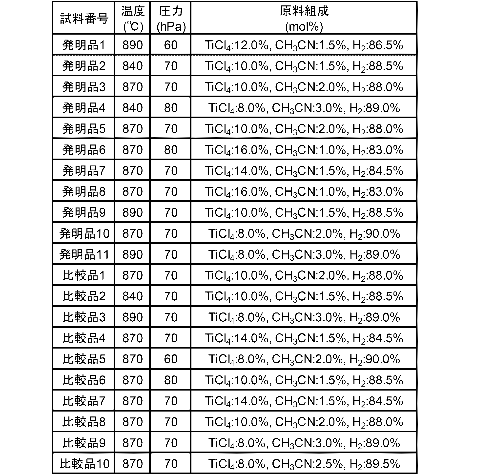
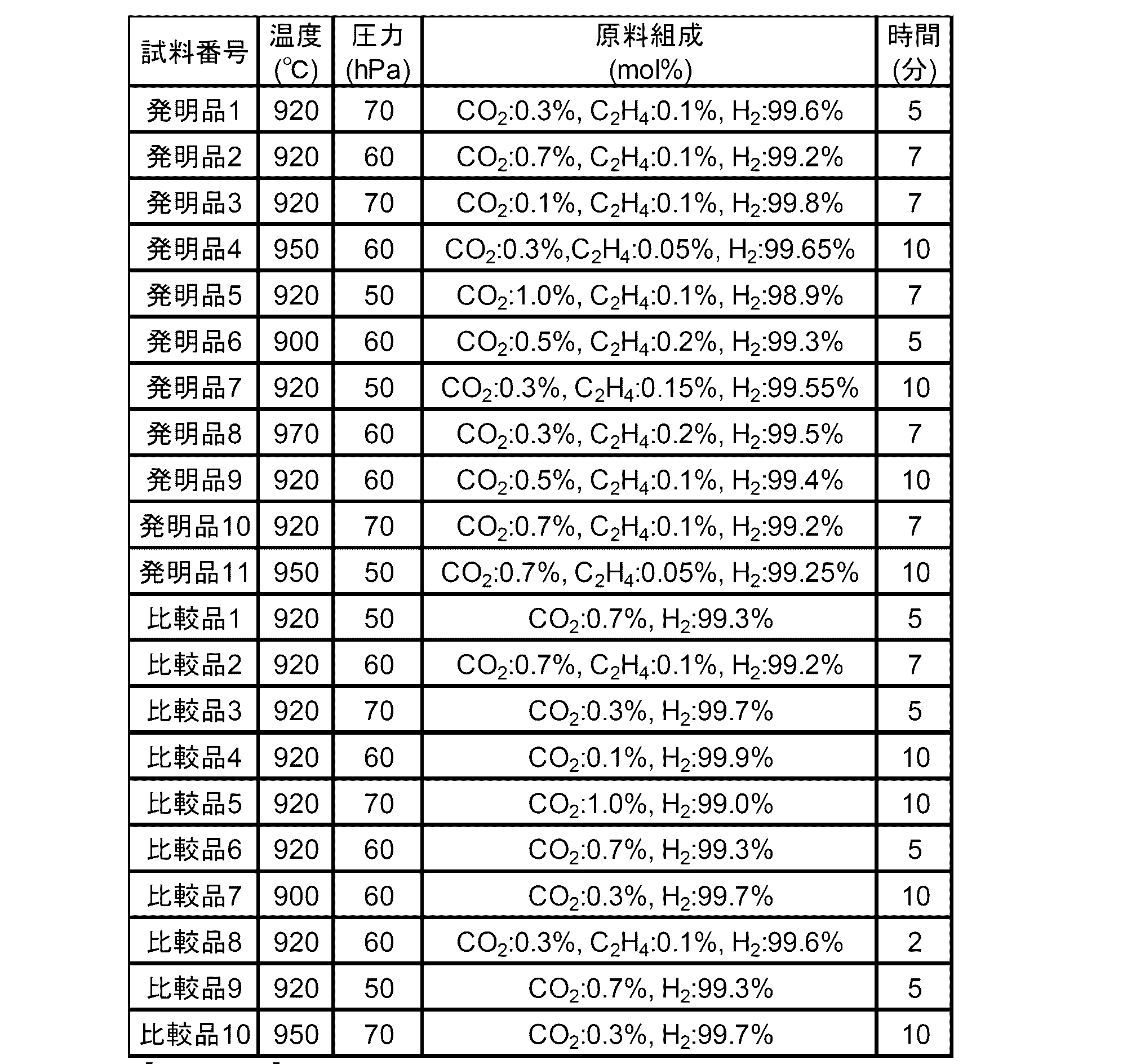


発明品1~11、比較品1~10については、基材の表面に被覆層を形成した後、表9に示す投射材を用いて、表9に示す投射条件の下、乾式ショットブラストを施した。
For invention products 1 to 11 and comparative products 1 to 10, after forming a coating layer on the surface of the base material, dry shot blasting was performed using the projection material shown in Table 9 under the projection conditions shown in Table 9. did.

得られた試料について、Cu-Kα線を用いた2θ/θ集中法光学系のX線回折測定を、出力:50kV、250mA、入射側ソーラースリット:5°、発散縦スリット:2/3°、発散縦制限スリット:5mm、散乱スリット:2/3°、受光側ソーラースリット:5°、受光スリット:0.3mm、BENTモノクロメータ、受光モノクロスリット:0.8mm、サンプリング幅:0.01°、スキャンスピード:4°/min、2θ測定範囲:20°~155°とする条件で行った。装置は、株式会社リガク製 X線回折装置RINT TTRIIIを用いた。X線回折図形からα型Al2O3層及びTiCN層の各面指数のピーク強度を求めた。得られた各面指数のピーク強度から、α型Al2O3層の組織係数TC(0,0,12)、TC(1,2,11)及びTiCN層の強度比I311/I220を求めた。その結果を、表10に示す。
With respect to the obtained sample, X-ray diffraction measurement of a 2θ / θ concentrated optical system using Cu—Kα rays was performed. Output: 50 kV, 250 mA, incident side solar slit: 5 °, divergent longitudinal slit: 2/3 °, Divergence length restriction slit: 5 mm, scattering slit: 2/3 °, light receiving side solar slit: 5 °, light receiving slit: 0.3 mm, BENT monochromator, light receiving monochrome slit: 0.8 mm, sampling width: 0.01 °, Scanning speed: 4 ° / min, 2θ measurement range: 20 ° to 155 °. As an apparatus, an X-ray diffraction apparatus RINT TTRIII manufactured by Rigaku Corporation was used. The peak intensity of each plane index of the α-type Al 2 O 3 layer and the TiCN layer was determined from the X-ray diffraction pattern. From the obtained peak intensity of each plane index, the structure ratio TC (0, 0, 12), TC (1, 2, 11) of the α-type Al 2 O 3 layer and the intensity ratio I 311 / I 220 of the TiCN layer are obtained. Asked. The results are shown in Table 10.
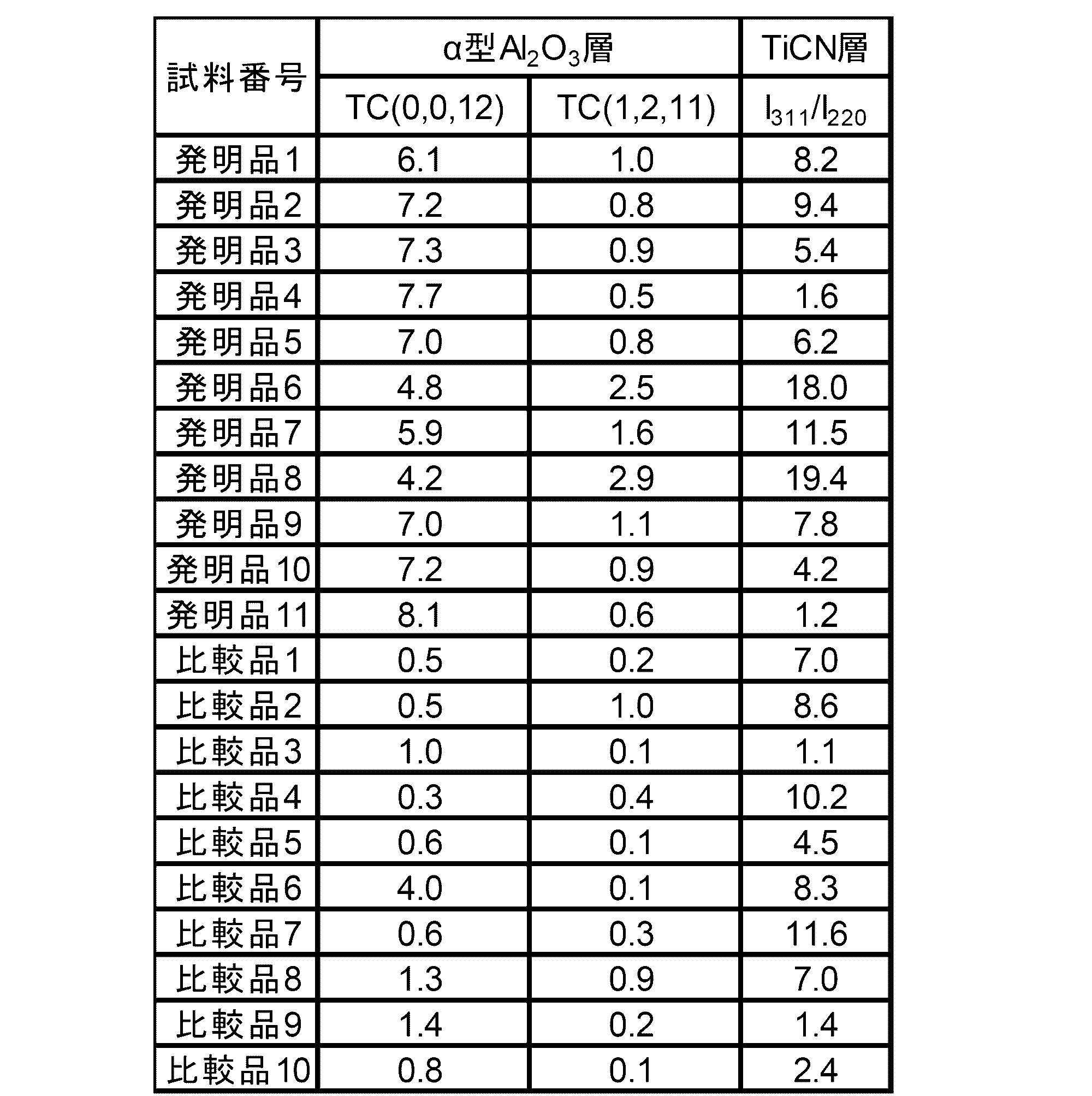
得られた試料のα型Al2O3層の残留応力は、X線応力測定装置を用いたsin2ψ法により測定した。その測定結果を表11に示す。
The residual stress of the α-type Al 2 O 3 layer of the obtained sample was measured by the sin 2 ψ method using an X-ray stress measurement apparatus. The measurement results are shown in Table 11.

得られた試料のα型Al2O3層の平均粒径は、EBSDにより測定した。その測定結果を表12に示す。
The average particle diameter of the α-type Al 2 O 3 layer of the obtained sample was measured by EBSD. The measurement results are shown in Table 12.

得られた試料を用いて、切削試験1及び切削試験2を行った。切削試験1は耐摩耗性を評価する試験であり、切削試験2は耐欠損性を評価する試験である。各切削試験の結果を表13に示す。
Cutting test 1 and cutting test 2 were performed using the obtained samples. Cutting test 1 is a test for evaluating wear resistance, and cutting test 2 is a test for evaluating chipping resistance. The results of each cutting test are shown in Table 13.
[切削試験1]
被削材:S50Cの丸棒、
切削速度:310m/min、
送り:0.30mm/rev、
切り込み:1.8mm、
クーラント:有り、
評価項目:試料が欠損又は最大逃げ面摩耗幅が0.2mmに至ったときを工具寿命とし、工具寿命までの加工時間を測定した。 [Cutting test 1]
Work material: S50C round bar,
Cutting speed: 310 m / min,
Feed: 0.30mm / rev,
Cutting depth: 1.8mm,
Coolant: Yes,
Evaluation item: When the sample was broken or the maximum flank wear width reached 0.2 mm, the tool life was determined, and the machining time until the tool life was measured.
[切削試験2]
被削材:S50Cの長さ方向に等間隔で2本の溝入り丸棒、
切削速度:260m/min、
送り:0.35mm/rev、
切り込み:1.5mm、
クーラント:有り、
評価項目:試料が欠損に至ったときを工具寿命とし、工具寿命までの衝撃回数を測定した。衝撃回数は、試料と被削材とが接触した回数とし、接触回数が最大で20000回に到達した時点で試験を終了した。なお、各試料について、5個のインサートを用意し、それぞれ衝撃回数を測定し、それらの衝撃回数の値から平均値を求め、工具寿命とした。 [Cutting test 2]
Work material: Two grooved round bars at equal intervals in the length direction of S50C,
Cutting speed: 260 m / min,
Feed: 0.35mm / rev,
Incision: 1.5mm,
Coolant: Yes,
Evaluation item: The time when the sample was damaged was regarded as the tool life, and the number of impacts until the tool life was measured. The number of impacts was defined as the number of times the sample and the work material contacted, and the test was terminated when the maximum number of contact reached 20000 times. For each sample, five inserts were prepared, the number of impacts was measured, and the average value was obtained from the value of the number of impacts to determine the tool life.
なお、耐摩耗性試験の工具寿命に至るまでの加工時間について、30分以上をA、20分以上30分未満をB、20分未満をCとして評価した。また、耐欠損性試験の工具寿命に至るまでの衝撃回数について、15000回以上をA、12000回以上15000回未満をB、12000回未満をCとして評価した。この評価では、「A」が最も優れており、次に「B」が優れており、「C」が最も劣っていることを意味し、A又はBの評価を有するほど切削性能が優れる。得られた総合評価の結果を表13に示す。
In addition, about the processing time until the tool life of the wear resistance test, 30 minutes or more was evaluated as A, 20 minutes or more and less than 30 minutes as B, and less than 20 minutes as C. Moreover, about the frequency | count of impact until it reaches the tool life of a fracture resistance test, 15000 times or more were evaluated as A, 12000 times or more and less than 15000 times as B, and less than 12000 times as C. In this evaluation, “A” is the best, next “B” is the best, and “C” is the most inferior. The higher the evaluation of A or B, the better the cutting performance. The obtained comprehensive evaluation results are shown in Table 13.

表13の結果より、発明品の耐摩耗性試験及び耐欠損性の評価は、どちらもA又はBの評価であった。一方、比較品の評価は、耐摩耗性試験又は耐欠損性試験のいずれかが、Cであった。特に、発明品の耐欠損性試験の評価はA又はBの評価であり、比較品の評価はB又はCであった。よって、発明品の耐欠損性は、比較品と比べ、同等以上であることが分かる。
From the results shown in Table 13, the wear resistance test and fracture resistance evaluation of the invention were both A or B evaluations. On the other hand, the evaluation of the comparative product was C in either the abrasion resistance test or the fracture resistance test. In particular, the evaluation of the defect resistance test of the inventive product was an evaluation of A or B, and the evaluation of the comparative product was B or C. Therefore, it can be seen that the fracture resistance of the invention product is equal to or greater than that of the comparative product.
以上の結果より、発明品は、耐摩耗性と耐欠損性に優れるため、工具寿命が長いことが分かる。
From the above results, it can be seen that the inventive product has a long tool life because it is excellent in wear resistance and fracture resistance.
本出願は、2016年10月25日出願の日本特許出願(特願2016-208559)に基づくものであり、その内容はここに参照として取り込まれる。
This application is based on a Japanese patent application (Japanese Patent Application No. 2016-208559) filed on October 25, 2016, the contents of which are incorporated herein by reference.
本発明の被覆切削工具は、耐摩耗性を低下させることなく、優れた耐欠損性を向上させることにより、従来よりも工具寿命を延長できるので、産業上の利用可能性が高い。
The coated cutting tool of the present invention has a high industrial applicability because the tool life can be extended more than before by improving the excellent fracture resistance without deteriorating the wear resistance.
Claims (11)
- 基材と、該基材の表面に形成された被覆層とを備える被覆切削工具であって、
前記被覆層が、少なくとも1層のα型酸化アルミニウム層を含み、
前記α型酸化アルミニウム層において、下記式(1)で表される(0,0,12)面の組織係数TC(0,0,12)が、4.0以上8.4以下であり、下記式(2)で表される(1,2,11)面の組織係数TC(1,2,11)が、0.5以上3.0以下である、被覆切削工具。


The coating layer includes at least one α-type aluminum oxide layer;
In the α-type aluminum oxide layer, the texture coefficient TC (0, 0, 12) of the (0, 0, 12) plane represented by the following formula (1) is 4.0 or more and 8.4 or less. A coated cutting tool in which the texture coefficient TC (1, 2, 11) of the (1, 2, 11) plane represented by the formula (2) is 0.5 or more and 3.0 or less.
- 前記α型酸化アルミニウム層において、前記組織係数TC(0,0,12)が、5.0以上8.2以下である、請求項1に記載の被覆切削工具。 The coated cutting tool according to claim 1, wherein in the α-type aluminum oxide layer, the texture coefficient TC (0, 0, 12) is 5.0 or more and 8.2 or less.
- 前記α型酸化アルミニウム層において、前記組織係数TC(1,2,11)が、1.0以上2.5以下である、請求項1又は2に記載の被覆切削工具。 The coated cutting tool according to claim 1 or 2, wherein in the α-type aluminum oxide layer, the texture coefficient TC (1, 2, 11) is 1.0 or more and 2.5 or less.
- 前記α型酸化アルミニウム層の(1,1,6)面における残留応力値が、少なくとも一部において、-300MPa以上300MPa以下である、請求項1~3のいずれか1項に記載の被覆切削工具。 The coated cutting tool according to any one of claims 1 to 3, wherein a residual stress value in the (1, 1, 6) plane of the α-type aluminum oxide layer is at least partly from -300 MPa to 300 MPa. .
- 前記α型酸化アルミニウム層の平均粒径が、0.1μm以上3.0μm以下である、請求項1~4のいずれか1項に記載の被覆切削工具。 The coated cutting tool according to any one of claims 1 to 4, wherein an average particle diameter of the α-type aluminum oxide layer is 0.1 µm or more and 3.0 µm or less.
- 前記α型酸化アルミニウム層の平均厚さが、1.0μm以上15.0μm以下である、請求項1~5のいずれか1項に記載の被覆切削工具。 The coated cutting tool according to any one of claims 1 to 5, wherein an average thickness of the α-type aluminum oxide layer is 1.0 µm or more and 15.0 µm or less.
- 前記被覆層が、前記基材と前記α型酸化アルミニウム層との間に、Tiと、C、N、O及びBからなる群より選ばれる少なくとも1種以上の元素とのTi化合物からなるTi化合物層を備える、請求項1~6のいずれか1項に記載の被覆切削工具。 A Ti compound in which the coating layer is composed of a Ti compound of Ti and at least one element selected from the group consisting of C, N, O and B between the base material and the α-type aluminum oxide layer The coated cutting tool according to any one of claims 1 to 6, comprising a layer.
- 前記Ti化合物層が、少なくとも1層のTiCN層を含み、前記TiCN層のX線回折における(2,2,0)面のピーク強度I220に対する、前記TiCN層のX線回折における(3,1,1)面のピーク折強度I311の比I311/I220が、1.5以上20.0以下である、請求項7に記載の被覆切削工具。 The Ti compound layer includes at least one TiCN layer, and (3, 1) in the X-ray diffraction of the TiCN layer with respect to the peak intensity I 220 of the (2, 2, 0) plane in the X-ray diffraction of the TiCN layer. , 1) The coated cutting tool according to claim 7, wherein the ratio I 311 / I 220 of the peak bending strength I 311 of the surface is 1.5 or more and 20.0 or less.
- 前記TiCN層の平均厚さが、2.0μm以上20.0μm以下である、請求項7又は8に記載の被覆切削工具。 The coated cutting tool according to claim 7 or 8, wherein an average thickness of the TiCN layer is 2.0 µm or more and 20.0 µm or less.
- 前記被覆層の平均厚さが、3.0μm以上30.0μm以下である、請求項1~9のいずれか1項に記載の被覆切削工具。 The coated cutting tool according to any one of claims 1 to 9, wherein an average thickness of the coating layer is 3.0 μm or more and 30.0 μm or less.
- 前記基材が、超硬合金、サーメット、セラミックス及び立方晶窒化硼素焼結体のいずれかである、請求項1~10のいずれか1項に記載の被覆切削工具。 The coated cutting tool according to any one of claims 1 to 10, wherein the base material is one of cemented carbide, cermet, ceramics, and cubic boron nitride sintered body.
Priority Applications (4)
| Application Number | Priority Date | Filing Date | Title |
|---|---|---|---|
| EP17865452.1A EP3533544B1 (en) | 2016-10-25 | 2017-10-06 | Coated cutting tool |
| JP2018547523A JP6955707B2 (en) | 2016-10-25 | 2017-10-06 | Cover cutting tool |
| CN201780066026.8A CN110023011B (en) | 2016-10-25 | 2017-10-06 | Coated cutting tool |
| US16/344,032 US10946453B2 (en) | 2016-10-25 | 2017-10-06 | Coated cutting tool |
Applications Claiming Priority (2)
| Application Number | Priority Date | Filing Date | Title |
|---|---|---|---|
| JP2016208559 | 2016-10-25 | ||
| JP2016-208559 | 2016-10-25 |
Publications (1)
| Publication Number | Publication Date |
|---|---|
| WO2018079229A1 true WO2018079229A1 (en) | 2018-05-03 |
Family
ID=62023423
Family Applications (1)
| Application Number | Title | Priority Date | Filing Date |
|---|---|---|---|
| PCT/JP2017/036421 WO2018079229A1 (en) | 2016-10-25 | 2017-10-06 | Coated cutting tool |
Country Status (5)
| Country | Link |
|---|---|
| US (1) | US10946453B2 (en) |
| EP (1) | EP3533544B1 (en) |
| JP (1) | JP6955707B2 (en) |
| CN (1) | CN110023011B (en) |
| WO (1) | WO2018079229A1 (en) |
Cited By (5)
| Publication number | Priority date | Publication date | Assignee | Title |
|---|---|---|---|---|
| WO2020174756A1 (en) * | 2019-02-26 | 2020-09-03 | 住友電工ハードメタル株式会社 | Cutting tool |
| WO2020174754A1 (en) * | 2019-02-26 | 2020-09-03 | 住友電工ハードメタル株式会社 | Cutting tool |
| WO2020174755A1 (en) * | 2019-02-26 | 2020-09-03 | 住友電工ハードメタル株式会社 | Cutting tool |
| US20220274892A1 (en) * | 2021-02-26 | 2022-09-01 | Tungaloy Corporation | Coated cutting tool |
| US11964329B2 (en) * | 2021-02-26 | 2024-04-23 | Tungaloy Corporation | Coated cutting tool |
Families Citing this family (3)
| Publication number | Priority date | Publication date | Assignee | Title |
|---|---|---|---|---|
| EP3848485A1 (en) * | 2020-01-10 | 2021-07-14 | Sakari Ruppi | Improved alpha alumina layer deposited with controlled textures |
| JP7103567B1 (en) * | 2021-03-22 | 2022-07-20 | 住友電工ハードメタル株式会社 | Cutting tools |
| JP7205039B1 (en) * | 2021-03-22 | 2023-01-17 | 住友電工ハードメタル株式会社 | Cutting tools |
Citations (5)
| Publication number | Priority date | Publication date | Assignee | Title |
|---|---|---|---|---|
| JPH11335870A (en) * | 1998-05-25 | 1999-12-07 | Hitachi Metals Ltd | Titanium carbonitride-aluminum oxide-coated tool |
| JP2008093769A (en) * | 2006-10-10 | 2008-04-24 | Mitsubishi Materials Corp | Surface coated cutting tool having hard coating layer exhibiting excellent chipping resistance |
| JP2014530112A (en) | 2011-09-16 | 2014-11-17 | バルター アクチェンゲゼルシャフト | Cutting insert and manufacturing method thereof |
| JP2016137564A (en) * | 2014-12-19 | 2016-08-04 | サンドビック インテレクチュアル プロパティー アクティエボラーグ | CVD coated cutting tool |
| JP2016208559A (en) | 2015-04-15 | 2016-12-08 | 株式会社明電舎 | Parallel operation method and parallel operation device for pwm power converter |
Family Cites Families (16)
| Publication number | Priority date | Publication date | Assignee | Title |
|---|---|---|---|---|
| SE526602C2 (en) * | 2003-10-27 | 2005-10-18 | Seco Tools Ab | Coated cutting for rough turning |
| EP2570510B2 (en) * | 2011-09-16 | 2019-02-13 | Walter AG | Sulfur containing alpha-alumina coated cutting tool |
| US9463513B2 (en) * | 2013-06-27 | 2016-10-11 | Sandvik Intellectual Property Ab | Coated cutting tool |
| CN105579171B (en) * | 2013-08-21 | 2017-12-01 | 株式会社泰珂洛 | Coated cutting tool |
| WO2015068792A1 (en) * | 2013-11-08 | 2015-05-14 | 株式会社タンガロイ | Coated cutting tool |
| CN105940141A (en) * | 2014-01-30 | 2016-09-14 | 山特维克知识产权股份有限公司 | Alumina coated cutting tool |
| EP2902528B1 (en) | 2014-01-30 | 2016-06-29 | Walter Ag | Alumina coated cutting tool with zigzag alumina grain boundaries |
| US10370758B2 (en) * | 2014-09-24 | 2019-08-06 | Kyocera Corporation | Coated tool |
| EP3034652A1 (en) | 2014-12-19 | 2016-06-22 | Sandvik Intellectual Property AB | CVD coated cutting tool |
| CN107427930B (en) * | 2015-01-28 | 2019-11-22 | 京瓷株式会社 | Coated tool |
| EP3417965B1 (en) * | 2016-02-18 | 2020-10-21 | Tungaloy Corporation | Coated cutting tool |
| KR102375084B1 (en) * | 2016-06-21 | 2022-03-15 | 산드빅 인터렉츄얼 프로퍼티 에이비 | CVD coated cutting tools |
| EP3263743A1 (en) * | 2016-06-29 | 2018-01-03 | Sandvik Intellectual Property AB | Cvd coated cutting tool |
| JP6229912B1 (en) * | 2016-10-21 | 2017-11-15 | 株式会社タンガロイ | Coated cutting tool |
| JP6210347B1 (en) * | 2016-11-04 | 2017-10-11 | 株式会社タンガロイ | Coated cutting tool |
| JP6973026B2 (en) * | 2017-02-20 | 2021-11-24 | 株式会社タンガロイ | Cover cutting tool |
-
2017
- 2017-10-06 WO PCT/JP2017/036421 patent/WO2018079229A1/en unknown
- 2017-10-06 EP EP17865452.1A patent/EP3533544B1/en active Active
- 2017-10-06 US US16/344,032 patent/US10946453B2/en active Active
- 2017-10-06 CN CN201780066026.8A patent/CN110023011B/en active Active
- 2017-10-06 JP JP2018547523A patent/JP6955707B2/en active Active
Patent Citations (5)
| Publication number | Priority date | Publication date | Assignee | Title |
|---|---|---|---|---|
| JPH11335870A (en) * | 1998-05-25 | 1999-12-07 | Hitachi Metals Ltd | Titanium carbonitride-aluminum oxide-coated tool |
| JP2008093769A (en) * | 2006-10-10 | 2008-04-24 | Mitsubishi Materials Corp | Surface coated cutting tool having hard coating layer exhibiting excellent chipping resistance |
| JP2014530112A (en) | 2011-09-16 | 2014-11-17 | バルター アクチェンゲゼルシャフト | Cutting insert and manufacturing method thereof |
| JP2016137564A (en) * | 2014-12-19 | 2016-08-04 | サンドビック インテレクチュアル プロパティー アクティエボラーグ | CVD coated cutting tool |
| JP2016208559A (en) | 2015-04-15 | 2016-12-08 | 株式会社明電舎 | Parallel operation method and parallel operation device for pwm power converter |
Non-Patent Citations (1)
| Title |
|---|
| See also references of EP3533544A4 |
Cited By (7)
| Publication number | Priority date | Publication date | Assignee | Title |
|---|---|---|---|---|
| WO2020174756A1 (en) * | 2019-02-26 | 2020-09-03 | 住友電工ハードメタル株式会社 | Cutting tool |
| WO2020174754A1 (en) * | 2019-02-26 | 2020-09-03 | 住友電工ハードメタル株式会社 | Cutting tool |
| WO2020174755A1 (en) * | 2019-02-26 | 2020-09-03 | 住友電工ハードメタル株式会社 | Cutting tool |
| JP6786763B1 (en) * | 2019-02-26 | 2020-11-18 | 住友電工ハードメタル株式会社 | Cutting tools |
| US11014165B2 (en) | 2019-02-26 | 2021-05-25 | Sumitomo Electric Hardmetal Corp. | Cutting tool |
| US20220274892A1 (en) * | 2021-02-26 | 2022-09-01 | Tungaloy Corporation | Coated cutting tool |
| US11964329B2 (en) * | 2021-02-26 | 2024-04-23 | Tungaloy Corporation | Coated cutting tool |
Also Published As
| Publication number | Publication date |
|---|---|
| EP3533544A4 (en) | 2020-04-01 |
| CN110023011A (en) | 2019-07-16 |
| US10946453B2 (en) | 2021-03-16 |
| EP3533544A1 (en) | 2019-09-04 |
| CN110023011B (en) | 2021-02-05 |
| EP3533544B1 (en) | 2023-08-09 |
| US20200038964A1 (en) | 2020-02-06 |
| JP6955707B2 (en) | 2021-10-27 |
| JPWO2018079229A1 (en) | 2019-07-04 |
Similar Documents
| Publication | Publication Date | Title |
|---|---|---|
| WO2018079229A1 (en) | Coated cutting tool | |
| JP6973026B2 (en) | Cover cutting tool | |
| JP6708261B2 (en) | Coated cutting tools | |
| EP3318661B2 (en) | Coated cutting tool | |
| JP6229911B1 (en) | Coated cutting tool | |
| JP6229912B1 (en) | Coated cutting tool | |
| EP3318660B2 (en) | Coated cutting tool | |
| JP7137143B2 (en) | coated cutting tools | |
| JP7137141B2 (en) | coated cutting tools | |
| WO2018079228A1 (en) | Coated cutting tool |
Legal Events
| Date | Code | Title | Description |
|---|---|---|---|
| 121 | Ep: the epo has been informed by wipo that ep was designated in this application |
Ref document number: 17865452 Country of ref document: EP Kind code of ref document: A1 |
|
| ENP | Entry into the national phase |
Ref document number: 2018547523 Country of ref document: JP Kind code of ref document: A |
|
| NENP | Non-entry into the national phase |
Ref country code: DE |
|
| ENP | Entry into the national phase |
Ref document number: 2017865452 Country of ref document: EP Effective date: 20190527 |