EP3318661B2 - Coated cutting tool - Google Patents
Coated cutting tool Download PDFInfo
- Publication number
- EP3318661B2 EP3318661B2 EP17199943.6A EP17199943A EP3318661B2 EP 3318661 B2 EP3318661 B2 EP 3318661B2 EP 17199943 A EP17199943 A EP 17199943A EP 3318661 B2 EP3318661 B2 EP 3318661B2
- Authority
- EP
- European Patent Office
- Prior art keywords
- layer
- aluminum oxide
- sample
- type aluminum
- oxide layer
- Prior art date
- Legal status (The legal status is an assumption and is not a legal conclusion. Google has not performed a legal analysis and makes no representation as to the accuracy of the status listed.)
- Active
Links
- 238000005520 cutting process Methods 0.000 title claims description 85
- 239000010410 layer Substances 0.000 claims description 198
- TWNQGVIAIRXVLR-UHFFFAOYSA-N oxo(oxoalumanyloxy)alumane Chemical compound O=[Al]O[Al]=O TWNQGVIAIRXVLR-UHFFFAOYSA-N 0.000 claims description 94
- ATJFFYVFTNAWJD-UHFFFAOYSA-N Tin Chemical compound [Sn] ATJFFYVFTNAWJD-UHFFFAOYSA-N 0.000 claims description 80
- 239000000758 substrate Substances 0.000 claims description 43
- 239000011247 coating layer Substances 0.000 claims description 38
- 239000002245 particle Substances 0.000 claims description 30
- 239000013078 crystal Substances 0.000 claims description 11
- BVKZGUZCCUSVTD-UHFFFAOYSA-L Carbonate Chemical compound [O-]C([O-])=O BVKZGUZCCUSVTD-UHFFFAOYSA-L 0.000 claims description 6
- 238000002441 X-ray diffraction Methods 0.000 claims description 6
- OSIVBHBGRFWHOS-UHFFFAOYSA-N dicarboxycarbamic acid Chemical compound OC(=O)N(C(O)=O)C(O)=O OSIVBHBGRFWHOS-UHFFFAOYSA-N 0.000 claims description 6
- 239000011195 cermet Substances 0.000 claims description 5
- 150000001875 compounds Chemical class 0.000 claims description 5
- 229910052582 BN Inorganic materials 0.000 claims description 4
- PZNSFCLAULLKQX-UHFFFAOYSA-N Boron nitride Chemical compound N#B PZNSFCLAULLKQX-UHFFFAOYSA-N 0.000 claims description 4
- 239000000919 ceramic Substances 0.000 claims description 4
- VSCWAEJMTAWNJL-UHFFFAOYSA-K aluminium trichloride Chemical group Cl[Al](Cl)Cl VSCWAEJMTAWNJL-UHFFFAOYSA-K 0.000 description 128
- 230000000052 comparative effect Effects 0.000 description 110
- 239000000203 mixture Substances 0.000 description 45
- PNEYBMLMFCGWSK-UHFFFAOYSA-N Alumina Chemical compound [O-2].[O-2].[O-2].[Al+3].[Al+3] PNEYBMLMFCGWSK-UHFFFAOYSA-N 0.000 description 28
- 239000002994 raw material Substances 0.000 description 27
- 229910052593 corundum Inorganic materials 0.000 description 26
- 229910001845 yogo sapphire Inorganic materials 0.000 description 26
- 238000005259 measurement Methods 0.000 description 15
- MCMNRKCIXSYSNV-UHFFFAOYSA-N Zirconium dioxide Chemical compound O=[Zr]=O MCMNRKCIXSYSNV-UHFFFAOYSA-N 0.000 description 14
- 229910003074 TiCl4 Inorganic materials 0.000 description 11
- XJDNKRIXUMDJCW-UHFFFAOYSA-J titanium tetrachloride Chemical group Cl[Ti](Cl)(Cl)Cl XJDNKRIXUMDJCW-UHFFFAOYSA-J 0.000 description 11
- 238000005229 chemical vapour deposition Methods 0.000 description 10
- 239000000463 material Substances 0.000 description 9
- 238000000034 method Methods 0.000 description 9
- 238000005336 cracking Methods 0.000 description 7
- 238000011156 evaluation Methods 0.000 description 7
- 230000035939 shock Effects 0.000 description 7
- 230000015572 biosynthetic process Effects 0.000 description 6
- 230000000694 effects Effects 0.000 description 6
- 238000005498 polishing Methods 0.000 description 6
- 238000005422 blasting Methods 0.000 description 5
- 238000000151 deposition Methods 0.000 description 5
- WEVYAHXRMPXWCK-UHFFFAOYSA-N Acetonitrile Chemical compound CC#N WEVYAHXRMPXWCK-UHFFFAOYSA-N 0.000 description 4
- 230000008021 deposition Effects 0.000 description 4
- 238000001887 electron backscatter diffraction Methods 0.000 description 4
- 238000010894 electron beam technology Methods 0.000 description 4
- 229910052594 sapphire Inorganic materials 0.000 description 4
- 239000011248 coating agent Substances 0.000 description 3
- 238000000576 coating method Methods 0.000 description 3
- VYPSYNLAJGMNEJ-UHFFFAOYSA-N Silicium dioxide Chemical compound O=[Si]=O VYPSYNLAJGMNEJ-UHFFFAOYSA-N 0.000 description 2
- 229910000831 Steel Inorganic materials 0.000 description 2
- 230000001133 acceleration Effects 0.000 description 2
- 239000008119 colloidal silica Substances 0.000 description 2
- 239000002826 coolant Substances 0.000 description 2
- 229910003460 diamond Inorganic materials 0.000 description 2
- 239000010432 diamond Substances 0.000 description 2
- 238000010438 heat treatment Methods 0.000 description 2
- 238000003754 machining Methods 0.000 description 2
- 230000003287 optical effect Effects 0.000 description 2
- 230000003647 oxidation Effects 0.000 description 2
- 238000007254 oxidation reaction Methods 0.000 description 2
- 239000010959 steel Substances 0.000 description 2
- 229910001018 Cast iron Inorganic materials 0.000 description 1
- 229910002483 Cu Ka Inorganic materials 0.000 description 1
- 229910000997 High-speed steel Inorganic materials 0.000 description 1
- 238000004458 analytical method Methods 0.000 description 1
- 230000005540 biological transmission Effects 0.000 description 1
- 238000006243 chemical reaction Methods 0.000 description 1
- 230000001419 dependent effect Effects 0.000 description 1
- -1 i.e. Chemical compound 0.000 description 1
- 238000003801 milling Methods 0.000 description 1
- 150000004767 nitrides Chemical class 0.000 description 1
- 230000005855 radiation Effects 0.000 description 1
- 102200082816 rs34868397 Human genes 0.000 description 1
- 238000005070 sampling Methods 0.000 description 1
- 238000005480 shot peening Methods 0.000 description 1
- 239000002356 single layer Substances 0.000 description 1
- 238000000992 sputter etching Methods 0.000 description 1
Classifications
-
- C—CHEMISTRY; METALLURGY
- C23—COATING METALLIC MATERIAL; COATING MATERIAL WITH METALLIC MATERIAL; CHEMICAL SURFACE TREATMENT; DIFFUSION TREATMENT OF METALLIC MATERIAL; COATING BY VACUUM EVAPORATION, BY SPUTTERING, BY ION IMPLANTATION OR BY CHEMICAL VAPOUR DEPOSITION, IN GENERAL; INHIBITING CORROSION OF METALLIC MATERIAL OR INCRUSTATION IN GENERAL
- C23C—COATING METALLIC MATERIAL; COATING MATERIAL WITH METALLIC MATERIAL; SURFACE TREATMENT OF METALLIC MATERIAL BY DIFFUSION INTO THE SURFACE, BY CHEMICAL CONVERSION OR SUBSTITUTION; COATING BY VACUUM EVAPORATION, BY SPUTTERING, BY ION IMPLANTATION OR BY CHEMICAL VAPOUR DEPOSITION, IN GENERAL
- C23C16/00—Chemical coating by decomposition of gaseous compounds, without leaving reaction products of surface material in the coating, i.e. chemical vapour deposition [CVD] processes
- C23C16/22—Chemical coating by decomposition of gaseous compounds, without leaving reaction products of surface material in the coating, i.e. chemical vapour deposition [CVD] processes characterised by the deposition of inorganic material, other than metallic material
- C23C16/30—Deposition of compounds, mixtures or solid solutions, e.g. borides, carbides, nitrides
- C23C16/40—Oxides
- C23C16/403—Oxides of aluminium, magnesium or beryllium
-
- C—CHEMISTRY; METALLURGY
- C23—COATING METALLIC MATERIAL; COATING MATERIAL WITH METALLIC MATERIAL; CHEMICAL SURFACE TREATMENT; DIFFUSION TREATMENT OF METALLIC MATERIAL; COATING BY VACUUM EVAPORATION, BY SPUTTERING, BY ION IMPLANTATION OR BY CHEMICAL VAPOUR DEPOSITION, IN GENERAL; INHIBITING CORROSION OF METALLIC MATERIAL OR INCRUSTATION IN GENERAL
- C23C—COATING METALLIC MATERIAL; COATING MATERIAL WITH METALLIC MATERIAL; SURFACE TREATMENT OF METALLIC MATERIAL BY DIFFUSION INTO THE SURFACE, BY CHEMICAL CONVERSION OR SUBSTITUTION; COATING BY VACUUM EVAPORATION, BY SPUTTERING, BY ION IMPLANTATION OR BY CHEMICAL VAPOUR DEPOSITION, IN GENERAL
- C23C16/00—Chemical coating by decomposition of gaseous compounds, without leaving reaction products of surface material in the coating, i.e. chemical vapour deposition [CVD] processes
- C23C16/22—Chemical coating by decomposition of gaseous compounds, without leaving reaction products of surface material in the coating, i.e. chemical vapour deposition [CVD] processes characterised by the deposition of inorganic material, other than metallic material
- C23C16/30—Deposition of compounds, mixtures or solid solutions, e.g. borides, carbides, nitrides
- C23C16/34—Nitrides
-
- C—CHEMISTRY; METALLURGY
- C23—COATING METALLIC MATERIAL; COATING MATERIAL WITH METALLIC MATERIAL; CHEMICAL SURFACE TREATMENT; DIFFUSION TREATMENT OF METALLIC MATERIAL; COATING BY VACUUM EVAPORATION, BY SPUTTERING, BY ION IMPLANTATION OR BY CHEMICAL VAPOUR DEPOSITION, IN GENERAL; INHIBITING CORROSION OF METALLIC MATERIAL OR INCRUSTATION IN GENERAL
- C23C—COATING METALLIC MATERIAL; COATING MATERIAL WITH METALLIC MATERIAL; SURFACE TREATMENT OF METALLIC MATERIAL BY DIFFUSION INTO THE SURFACE, BY CHEMICAL CONVERSION OR SUBSTITUTION; COATING BY VACUUM EVAPORATION, BY SPUTTERING, BY ION IMPLANTATION OR BY CHEMICAL VAPOUR DEPOSITION, IN GENERAL
- C23C28/00—Coating for obtaining at least two superposed coatings either by methods not provided for in a single one of groups C23C2/00 - C23C26/00 or by combinations of methods provided for in subclasses C23C and C25C or C25D
- C23C28/04—Coating for obtaining at least two superposed coatings either by methods not provided for in a single one of groups C23C2/00 - C23C26/00 or by combinations of methods provided for in subclasses C23C and C25C or C25D only coatings of inorganic non-metallic material
- C23C28/042—Coating for obtaining at least two superposed coatings either by methods not provided for in a single one of groups C23C2/00 - C23C26/00 or by combinations of methods provided for in subclasses C23C and C25C or C25D only coatings of inorganic non-metallic material including a refractory ceramic layer, e.g. refractory metal oxides, ZrO2, rare earth oxides
-
- B—PERFORMING OPERATIONS; TRANSPORTING
- B23—MACHINE TOOLS; METAL-WORKING NOT OTHERWISE PROVIDED FOR
- B23B—TURNING; BORING
- B23B27/00—Tools for turning or boring machines; Tools of a similar kind in general; Accessories therefor
- B23B27/14—Cutting tools of which the bits or tips or cutting inserts are of special material
-
- C—CHEMISTRY; METALLURGY
- C23—COATING METALLIC MATERIAL; COATING MATERIAL WITH METALLIC MATERIAL; CHEMICAL SURFACE TREATMENT; DIFFUSION TREATMENT OF METALLIC MATERIAL; COATING BY VACUUM EVAPORATION, BY SPUTTERING, BY ION IMPLANTATION OR BY CHEMICAL VAPOUR DEPOSITION, IN GENERAL; INHIBITING CORROSION OF METALLIC MATERIAL OR INCRUSTATION IN GENERAL
- C23C—COATING METALLIC MATERIAL; COATING MATERIAL WITH METALLIC MATERIAL; SURFACE TREATMENT OF METALLIC MATERIAL BY DIFFUSION INTO THE SURFACE, BY CHEMICAL CONVERSION OR SUBSTITUTION; COATING BY VACUUM EVAPORATION, BY SPUTTERING, BY ION IMPLANTATION OR BY CHEMICAL VAPOUR DEPOSITION, IN GENERAL
- C23C16/00—Chemical coating by decomposition of gaseous compounds, without leaving reaction products of surface material in the coating, i.e. chemical vapour deposition [CVD] processes
- C23C16/22—Chemical coating by decomposition of gaseous compounds, without leaving reaction products of surface material in the coating, i.e. chemical vapour deposition [CVD] processes characterised by the deposition of inorganic material, other than metallic material
- C23C16/30—Deposition of compounds, mixtures or solid solutions, e.g. borides, carbides, nitrides
- C23C16/308—Oxynitrides
-
- C—CHEMISTRY; METALLURGY
- C23—COATING METALLIC MATERIAL; COATING MATERIAL WITH METALLIC MATERIAL; CHEMICAL SURFACE TREATMENT; DIFFUSION TREATMENT OF METALLIC MATERIAL; COATING BY VACUUM EVAPORATION, BY SPUTTERING, BY ION IMPLANTATION OR BY CHEMICAL VAPOUR DEPOSITION, IN GENERAL; INHIBITING CORROSION OF METALLIC MATERIAL OR INCRUSTATION IN GENERAL
- C23C—COATING METALLIC MATERIAL; COATING MATERIAL WITH METALLIC MATERIAL; SURFACE TREATMENT OF METALLIC MATERIAL BY DIFFUSION INTO THE SURFACE, BY CHEMICAL CONVERSION OR SUBSTITUTION; COATING BY VACUUM EVAPORATION, BY SPUTTERING, BY ION IMPLANTATION OR BY CHEMICAL VAPOUR DEPOSITION, IN GENERAL
- C23C16/00—Chemical coating by decomposition of gaseous compounds, without leaving reaction products of surface material in the coating, i.e. chemical vapour deposition [CVD] processes
- C23C16/22—Chemical coating by decomposition of gaseous compounds, without leaving reaction products of surface material in the coating, i.e. chemical vapour deposition [CVD] processes characterised by the deposition of inorganic material, other than metallic material
- C23C16/30—Deposition of compounds, mixtures or solid solutions, e.g. borides, carbides, nitrides
- C23C16/36—Carbonitrides
-
- C—CHEMISTRY; METALLURGY
- C23—COATING METALLIC MATERIAL; COATING MATERIAL WITH METALLIC MATERIAL; CHEMICAL SURFACE TREATMENT; DIFFUSION TREATMENT OF METALLIC MATERIAL; COATING BY VACUUM EVAPORATION, BY SPUTTERING, BY ION IMPLANTATION OR BY CHEMICAL VAPOUR DEPOSITION, IN GENERAL; INHIBITING CORROSION OF METALLIC MATERIAL OR INCRUSTATION IN GENERAL
- C23C—COATING METALLIC MATERIAL; COATING MATERIAL WITH METALLIC MATERIAL; SURFACE TREATMENT OF METALLIC MATERIAL BY DIFFUSION INTO THE SURFACE, BY CHEMICAL CONVERSION OR SUBSTITUTION; COATING BY VACUUM EVAPORATION, BY SPUTTERING, BY ION IMPLANTATION OR BY CHEMICAL VAPOUR DEPOSITION, IN GENERAL
- C23C28/00—Coating for obtaining at least two superposed coatings either by methods not provided for in a single one of groups C23C2/00 - C23C26/00 or by combinations of methods provided for in subclasses C23C and C25C or C25D
- C23C28/04—Coating for obtaining at least two superposed coatings either by methods not provided for in a single one of groups C23C2/00 - C23C26/00 or by combinations of methods provided for in subclasses C23C and C25C or C25D only coatings of inorganic non-metallic material
- C23C28/044—Coating for obtaining at least two superposed coatings either by methods not provided for in a single one of groups C23C2/00 - C23C26/00 or by combinations of methods provided for in subclasses C23C and C25C or C25D only coatings of inorganic non-metallic material coatings specially adapted for cutting tools or wear applications
-
- B—PERFORMING OPERATIONS; TRANSPORTING
- B23—MACHINE TOOLS; METAL-WORKING NOT OTHERWISE PROVIDED FOR
- B23B—TURNING; BORING
- B23B2228/00—Properties of materials of tools or workpieces, materials of tools or workpieces applied in a specific manner
- B23B2228/10—Coatings
- B23B2228/105—Coatings with specified thickness
Definitions
- the present invention relates to a coated cutting tool.
- a coated cutting tool which is obtained by depositing, via chemical vapor deposition, a coating layer with a total thickness of from 3 ⁇ m or more to 20 ⁇ m or less on a surface of a substrate consisting of a cemented carbide.
- a known example of the above coating layer is a coating layer consisting of a single layer of one kind selected from the group consisting of a Ti carbide, a Ti nitride, a Ti carbonitride, a Ti carbonate, a Ti carboxynitride, and aluminum oxide, or consisting of multiple layers of two or more kinds selected therefrom.
- JP2007-125686 A discloses a cutting tool insert in which the layers thereof include at least one ⁇ -alumina layer, wherein a texture coefficient TC (006) of the ⁇ -alumina layer satisfies TC (006) > 1.4, which indicates a manifestation of a strong ⁇ 001> texture.
- JP2015-009358 A discloses a coated cutting tool comprising a substrate and a coating, wherein the coating comprises a layer of MTCVD TiCN and a layer of ⁇ -Al 2 O 3 , wherein a TC (0012) of the layer of ⁇ -Al 2 O 3 is higher than 5 and a full width half maximum (FWHM) of a rocking curve peak of a (0012) plane of the layer of ⁇ -Al 2 O 3 is lower than 30°.
- a TC (0012) of the layer of ⁇ -Al 2 O 3 is higher than 5
- FWHM full width half maximum
- EP 3 034 653 A1 discloses a coated cutting tool comprising a substrate coated with a coating comprising a layer of ⁇ -Al2O3, wherein the ⁇ -Al2O3layer exhibits a texture coefficient TC(0 0 12) ⁇ 7.2.
- the present invention has been made in order to solve this problem, and an object of the present invention is to provide a coated cutting tool which has excellent fracture resistance, as the occurrence of cracking is suppressed even under cutting conditions which involve a high temperature, and thereby allows the tool life to be extended.
- a coated cutting tool as recited in the independent claim is provided.
- the dependent claims define embodiments.
- the present inventor has conducted studies regarding extending the tool life of a coated cutting tool from the above-described perspective and has then found that the following configurations, including optimizing the crystal orientation in a predetermined plane of an ⁇ -type aluminum oxide layer, allow the fracture resistance to be improved, as the occurrence of cracking is suppressed even under cutting conditions which involve a high temperature, and found that, as a result, the tool life of the coated cutting tool can be extended, and this has led to the completion of the present invention.
- the present invention can provide a coated cutting tool which has excellent fracture resistance, as the occurrence of cracking is suppressed even under cutting conditions which involve a high temperature, and thereby allows the tool life to be extended.
- a coated cutting tool comprises a substrate and a coating layer formed on a surface of the substrate.
- Specific examples of types of the coated cutting tool include an indexable cutting insert for milling or turning, a drill and an end mill.
- the substrate in the present embodiment is not particularly limited, as long as it may be used as a substrate for the coated cutting tool.
- examples of such substrate include a cemented carbide, cermet, ceramic, a sintered body containing cubic boron nitride, a diamond sintered body and high-speed steel.
- the substrate is preferably comprised of any of a cemented carbide, cermet, ceramics and a sintered body containing cubic boron nitride, as this provides excellent wear resistance and fracture resistance, and, from the same perspective, the substrate is more preferably comprised of a cemented carbide.
- the surface of the substrate may be modified.
- a ⁇ -free layer may be formed on the surface thereof
- a hardened layer may be formed on the surface thereof.
- the average thickness thereof is preferably from 3.0 ⁇ m or more to 30.0 ⁇ m or less. If the average thickness is 3.0 ⁇ m or more, this indicates the tendency of the wear resistance to be further improved, and if such average thickness is 30.0 ⁇ m or less, this indicates the tendency of the adhesion with the substrate of the coating layer and the fracture resistance to be further increased. From the same perspective, the average thickness of the coating layer is more preferably from 5.0 ⁇ m or more to 27.0 ⁇ m or less.
- each of such average thicknesses can be obtained by: measuring the thickness of each layer or the thickness of the entire coating layer from each of the cross-sectional surfaces at three or more locations in each layer or in the entire coating layer; and calculating the arithmetic mean of the resulting measurements.
- the coating layer in the present embodiment includes at least one ⁇ -type aluminum oxide layer.
- a texture coefficient TC (1,1,9) of a (1,1,9) plane represented by formula (1) below is 4.0 or more.
- the texture coefficient TC (1,1,9) is 4.0 or more, the ratio of a peak intensity I (1,1,9) for the (1,1,9) plane is high, resulting in excellent fracture resistance because the occurrence of cracking can be suppressed even under cutting conditions which involve a high temperature.
- the texture coefficient TC (1,1,9) in the ⁇ -type aluminum oxide layer is 4.0 or more.
- the texture coefficient TC (1,1,9) is preferably 7.2 or less, and is more preferably 6.9 or less.
- I (h,k,l) denotes a peak intensity for an (h,k,l) plane in X-ray diffraction of the ⁇ -type aluminum oxide layer
- I 0 (h,k,l) denotes a standard diffraction intensity for the (h,k,l) plane which is indicated on a JCPDS Card No. 10-0173 for ⁇ -type aluminum oxide
- (h,k,l) refers to eight crystal planes of (0,1,2), (1,0,4), (1,1,0), (1,1,3), (0,2,4), (1,1,6), (2,1,4) and (1,1,9).
- I (1,1,9) denotes a peak intensity for the (1,1,9) plane in X-ray diffraction of the ⁇ -type aluminum oxide layer
- I 0 (1,1,9) denotes a standard diffraction intensity for the (1,1,9) plane which is indicated on a JCPDS Card No. 10-0173 for ⁇ -type aluminum oxide.
- the standard diffraction intensities for the respective crystal planes are 75.0 for a (0,1,2) plane, 90.0 for a (1,0,4) plane, 40.0 for a (1,1,0) plane, 100.0 for a (1,1,3) plane, 45.0 for a (0,2,4) plane, 80.0 for a (1,1,6) plane, 30.0 for a (2,1,4) plane and 8.0 for a (1,1,9) plane.
- the texture coefficient TC (1,1,9) is 1.4 or more, this indicates the tendency of the ⁇ -type aluminum oxide layer to have preferential orientation of the (1,1,9) plane.
- the texture coefficient of the (1,1,9) plane is greater than the TC of any of the other crystal planes in light of the point that the total of the TCs of the respective crystal planes is 8.0 or more.
- the texture coefficient TC (1,1,9) is 4.0 or more, the ⁇ -type aluminum oxide layer has the most preferential orientation of the (1,1,9) plane.
- the average thickness of the ⁇ -type aluminum oxide layer of the present embodiment is preferably from 1.0 ⁇ m or more to 15.0 ⁇ m or less. If the average thickness of the ⁇ -type aluminum oxide layer is 1.0 ⁇ m or more, this indicates the tendency of the crater wear resistance in the rake surface of the coated cutting tool to be further improved, and if such average thickness is 15.0 ⁇ m or less, this indicates the tendency of the fracture resistance of the coated cutting tool to be further improved as the peeling of the coating layer is further suppressed. From the same perspective, the average thickness of the ⁇ -type aluminum oxide layer is preferably from 1.5 ⁇ m or more to 12.0 ⁇ m or less, and is further preferably from 3.0 ⁇ m or more to 10.0 ⁇ m or less.
- the residual stress value in a (1,1,6) plane of the ⁇ -type aluminum oxide layer is, at least in part thereof, preferably from -300 MPa or higher to 300 MPa or lower. If the residual stress value is -300 MPa or higher, this indicates the tendency of the wear resistance to be improved because the progress of wear - which starts from the time when particles fall off from the ⁇ -type aluminum oxide layer - can be further suppressed. Further, if the residual stress value is 300 MPa or lower, this indicates the tendency of the fracture resistance of the coated cutting tool to be further improved because the generation of cracking in the ⁇ -type aluminum oxide layer can be further suppressed. From the same perspective, the residual stress value in the (1,1,6) plane of the ⁇ -type aluminum oxide layer is more preferably from -250 MPa or higher to 250 MPa or lower.
- the term "at least in part thereof" indicates that, it is not necessary to satisfy, in the entire ⁇ -type aluminum oxide layer, the above residual stress value range in the (1,1,6) plane of the ⁇ -type aluminum oxide layer, and such term also indicates that it is only required to satisfy the above residual stress value range in the (1,1,6) plane of the ⁇ -type aluminum oxide layer in a specific area such as a rake surface.
- the residual stress value of the ⁇ -type aluminum oxide layer can be measured by a sin 2 ⁇ method using an X-ray stress measuring apparatus. It is preferable to measure, via the sin 2 ⁇ method, the residual stresses at any three points included in the coating layer and to obtain the arithmetic mean of the residual stresses at such three points. Any three points, serving as measurement locations, in the ⁇ -type aluminum oxide layer are preferably selected in such a way as to be 0.1 mm or more apart from one another.
- the (1,1,6) plane of the ⁇ -type aluminum oxide layer which serves as a measurement subject is selected for measurement. More specifically, a sample in which an ⁇ -type aluminum oxide layer is formed is subjected to analysis with an X-ray diffractometer. Then, an examination is conducted regarding variations in the diffraction angle of the (1,1,6) plane when a change is made to an angle ⁇ formed by a sample plane normal and a lattice plane normal.
- the average particle size of the ⁇ -type aluminum oxide layer is preferably from 0.1 ⁇ m or more to 3.0 ⁇ m or less. This is preferable in that: if the average particle size of the ⁇ -type aluminum oxide layer is 0.1 ⁇ m or more, the fracture resistance is further enhanced; and, if such average particle size is 3.0 ⁇ m or less, the wear resistance is further improved because the progress of wear due to the falling of particles is suppressed. From the same perspective, the average particle size of the ⁇ -type aluminum oxide layer is more preferably from 0.4 ⁇ m or more to 2.5 ⁇ m or less.
- the average particle size of the ⁇ -type aluminum oxide layer can be obtained by observing a cross-sectional structure of the ⁇ -type aluminum oxide layer using a commercially available electron backscatter diffraction pattern apparatus (EBSD) attached to a field emission scanning electron microscope (FE-SEM) or to a transmission electron microscope (TEM). More specifically, mirror polishing is performed on a cross-section in a direction parallel or substantially parallel to a surface of the substrate of the coated cutting tool, and the resulting mirror-polished surface is regarded as a cross-sectional structure.
- Examples of a method of mirror-polishing an ⁇ -type aluminum oxide layer include: a polishing method with the use of diamond paste or colloidal silica; and ion milling.
- a sample of a coated cutting tool is set on an FE-SEM such that a cross-sectional structure of an ⁇ -type aluminum oxide layer can be irradiated with an electron beam, and the sample is then irradiated with an electron beam under the conditions of an angle of incidence of 70 degrees, an acceleration voltage of 15 kV, and an irradiation current of 0.5 nA.
- Measurement is desirably performed under the EBSD settings of a measurement range of 30 ⁇ m x 50 ⁇ m and a step size of 0.1 ⁇ m.
- a particle is defined as an area surrounded by a structure boundary with a misorientation of 5 degrees or more.
- the diameter of a circle whose area is equal to the area of a particle is regarded as a particle size of such particle.
- Image analysis software may be used when obtaining a particle size of the cross-sectional structure of the ⁇ -type aluminum oxide layer.
- the particle sizes in the ⁇ -type aluminum oxide layer are measured with regard to a range of 30 ⁇ m x 50 ⁇ m, and the average value (arithmetic mean) of all the obtained particle sizes is regarded as an average particle size.
- the ⁇ -type aluminum oxide layer is a layer comprised of ⁇ -type aluminum oxide.
- ⁇ -type aluminum oxide layer may contain a very small amount of components other than ⁇ -type aluminum oxide, as long as it comprises the configuration of the present embodiment and provides the operation and effects of the present invention.
- the coating layer of the present embodiment comprises a TiCN layer between the substrate and the ⁇ -type aluminum oxide layer, as this improves wear resistance.
- the average thickness of the TiCN layer of the present embodiment is preferably from 2.0 ⁇ m or more to 20.0 ⁇ m or less. If the average thickness of the TiCN layer is 2.0 ⁇ m or more, this indicates the tendency of the wear resistance of the coated cutting tool to be further improved, and, if such average thickness is 20.0 ⁇ m or less, this indicates the tendency of the fracture resistance of the coated cutting tool to be further improved as the peeling of the coating layer is further suppressed. From the same perspective, the average thickness of the TiCN layer is more preferably from 5.0 ⁇ m or more to 15.0 ⁇ m or less.
- the TiCN layer is a layer comprised of TiCN.
- such TiCN layer may contain a very small amount of components other than TiCN, as long as it comprises the above-described configuration and provides the operation and effects of the TiCN layer.
- the coating layer of the present embodiment includes, between the TiCN layer and the ⁇ -type aluminum oxide layer, an intermediate layer comprised of a compound of at least one kind selected from the group consisting of a Ti carbonate, a Ti oxynitride and a Ti carboxynitride as the adhesion is further improved.
- the average thickness of such intermediate layer is preferably from 0.2 ⁇ m or more to 1.5 ⁇ m or less.
- the average thickness of the intermediate layer is 0.2 ⁇ m or more, this indicates the tendency of the adhesion to be further improved; and, if such average thickness is 1.5 ⁇ m or less, this indicates the tendency of the texture coefficient TC (1,1,9) of the (1,1,9) plane in the ⁇ -type aluminum oxide layer to have a greater value.
- the intermediate layer is a layer comprised of a compound of at least one kind selected from the group consisting of a Ti carbonate, a Ti oxynitride and a Ti carboxynitride.
- a Ti carbonate a Ti oxynitride
- Ti carboxynitride a Ti carboxynitride.
- such intermediate layer may contain a very small amount of components other than the above compound, as long as it comprises the above-described configuration and provides the operation and effects of the intermediate layer.
- the coating layer of the present embodiment comprises a TiN layer as an outermost layer on a side opposite to the substrate as this makes it possible to confirm the usage state, such as whether or not the coated cutting tool has been used, thereby leading to excellent visibility.
- the average thickness of the TiN layer is from 0.2 ⁇ m or more to 1.0 ⁇ m or less. This is preferable in that: if the average thickness of the TiN layer is 0.2 ⁇ m or more, this provides the effect of further suppressing the falling of particles from the ⁇ -type aluminum oxide layer; and, if such average thickness is 1.0 ⁇ m or less, the fracture resistance of the coated cutting tool is improved.
- the coating layer of the present embodiment preferably comprises, between the substrate and the TiCN layer, a TiN layer serving as a lowermost layer in the coating layer, as this leads to adhesion being improved.
- the average thickness of this TiN layer is preferably from 0.1 ⁇ m or more to 0.5 ⁇ m or less. If the average thickness of the TiN layer is 0.1 ⁇ m or more, this indicates the tendency of the adhesion to be further improved as the TiN layer has a more uniform structure. Meanwhile, if the average thickness of the TiN layer is 0.5 ⁇ m or less, this indicates the tendency of the fracture resistance to be further enhanced as the TiN layer, being the lowermost layer, is further prevented from serving as a starting point of peeling.
- TiN layers respectively serving as the outermost layer and the lowermost layer are each a layer comprised of TiN.
- such TiN layers may each contain a very small amount of components other than TiN, as long as they respectively comprise the above-described configurations and provide the operation and effects of the outermost layer and the lowermost layer.
- Examples of a method of forming layers that constitute a coating layer in a coated cutting tool according to the present invention include the method set forth below. However, such method of forming layers is not limited thereto.
- a TiN layer can be formed by chemical vapor deposition with a raw material gas composition of TiCl 4 : from 5.0 mol% or more to 10.0 mol% or less, N 2 : from 20 mol% or more to 60 mol% or less, and H 2 : the balance, a temperature of from 850°C or higher to 920°C or lower, and a pressure of from 100 hPa or higher to 400 hPa or lower.
- a TiCN layer can be formed by chemical vapor deposition with a raw material gas composition of TiCl 4 : from 8.0 mol% or more to 18.0 mol% or less, CH 3 CN: from 1.0 mol% or more to 3.0 mol% or less, and H 2 : the balance, a temperature of from 840°C or higher to 890°C or lower, and a pressure of from 60 hPa or higher to 80 hPa or lower.
- the peak intensity ratio I 422 /I 220 of the TiCN layer can be adjusted so as to fall within a range of from 1.5 or more to 20.0 or less by controlling the molar ratio of TiCl 4 to CH 3 CN, i.e., TiCl 4 /CH 3 CN, so as to be from 4.0 or more to 8.0 or less.
- a TiCNO layer being a layer comprised of a Ti carboxynitride, can be formed by chemical vapor deposition with a raw material gas composition of TiCl 4 : from 3.0 mol% or more to 5.0 mol% or less, CO: from 0.4 mol% or more to 1.0 mol% or less, N 2 : from 30 mol% or more to 40 mol% or less, and H 2 : the balance, a temperature of from 975°C or higher to 1,025°C or lower, and a pressure of from 90 hPa or higher to 110 hPa or lower.
- a TiCO layer being a layer comprised of a Ti carbonate, can be formed by chemical vapor deposition with a raw material gas composition of TiCl 4 : from 0.5 mol% or more to 1.5 mol% or less, CO: from 2.0 mol% or more to 4.0 mol% or less, and H 2 : the balance, a temperature of from 975°C or higher to 1,025°C or lower, and a pressure of from 60 hPa or higher to 100 hPa or lower.
- a coated cutting tool which involves the controlled orientation (orientation relationship) of an ⁇ -type aluminum oxide layer can be obtained by, for example, the method set forth below.
- one or more layers selected from the group consisting of a TiCN layer, if necessary, a TiN layer, also if necessary, and the intermediate layer is(are) formed on a surface of a substrate.
- a surface of a layer which is most distant from the substrate is oxidized.
- a nucleus of an ⁇ -type aluminum oxide layer is formed on the surface of the layer which is most distant from the substrate, and an ⁇ -type aluminum oxide layer is then formed in the state in which such nucleus has been formed.
- a TiN layer may be formed on a surface of the ⁇ -type aluminum oxide layer.
- the oxidation of the surface of the layer which is most distant from the substrate is performed under the conditions of a raw material gas composition of CO 2 : from 0.1 mol% or more to 1.0 mol% or less, H 2 S: from 0.05 mol% or more to 0.15 mol% or less, and H 2 : the balance, a temperature of from 900°C or higher to 950°C or lower, and a pressure of from 50 hPa or higher to 70 hPa or lower.
- the oxidation time is preferably from 1 minute or more to 3 minutes or less.
- the nucleus of the ⁇ -type aluminum oxide layer is formed by chemical vapor deposition with a raw material gas composition of AlCl 3 : from 2.0 mol% or more to 5.0 mol% or less, CO 2 : from 2.5 mol% or more to 4.0 mol% or less, HCl: from 2.0 mol% or more to 3.0 mol% or less, C 3 H 6 : from 0.05 mol% or more to 0.2 mol% or less, and H 2 : the balance, a temperature of from 970°C or higher to 1,030°C or lower, and a pressure of from 60 hPa or higher to 80 hPa or lower.
- a raw material gas composition of AlCl 3 : from 2.0 mol% or more to 5.0 mol% or less, CO 2 : from 2.5 mol% or more to 4.0 mol% or less, HCl: from 2.0 mol% or more to 3.0 mol% or less, C 3 H 6 : from 0.05 mol% or more to 0.2 mol
- the ⁇ -type aluminum oxide layer is then formed by chemical vapor deposition with a raw material gas composition of AlCl 3 : from 2.0 mol% or more to 5.0 mol% or less, CO 2 : from 2.5 mol% or more to 4.0 mol% or less, HCl: from 2.0 mol% or more to 3.0 mol% or less, H 2 S: from 0.15 mol% or more to 0.25 mol% or less, and H 2 : the balance, a temperature of from 970°C or higher to 1,050°C or lower, and a pressure of from 60 hPa or higher to 80 hPa or lower.
- a surface of the TiN layer, the TiCN layer or the intermediate layer is oxidized, the nucleus of the ⁇ -type aluminum oxide layer is then formed, and the ⁇ -type aluminum oxide layer is then formed with normal conditions, thereby making it possible to obtain an ⁇ -type aluminum oxide layer with a texture coefficient TC (1,1,9) of 1.4 or more.
- a shot material may be shot onto a surface of the coating layer at a shot velocity of from 50 m/sec or more to 80 m/sec or less and for a shot time of from 0.5 minutes or more to 3 minutes or less so as to achieve a shot angle of from 30° or more to 70° or less.
- the shot material (medium) in dry shot blasting is preferably a material(s) of one or more kinds, each of which has an average particle size of from 100 ⁇ m or more to 150 ⁇ m or less and is(are) selected from the group consisting of Al 2 O 3 and ZrO 2 .
- each layer in the coating layer of the coated cutting tool of the present embodiment can be measured by observing a cross-sectional structure of the coated cutting tool, using an optical microscope, a scanning electron microscope (SEM), an FE-SEM, or the like. It should be noted that, as to the average thickness of each layer in the coated cutting tool of the present embodiment, such average thickness can be obtained by: measuring the thickness of each layer at three or more locations near the position 50 ⁇ m from the edge, toward the center of the rake surface of the coated cutting tool; and calculating the arithmetic mean of the resulting measurements.
- composition of each layer can be measured from a cross-sectional structure of the coated cutting tool of the present embodiment, using an energy-dispersive X-ray spectroscope (EDS), a wavelength-dispersive X-ray spectroscope (WDS) or the like.
- EDS energy-dispersive X-ray spectroscope
- WDS wavelength-dispersive X-ray spectroscope
- a cemented carbide cutting insert with a shape of JIS certified CNMA120408 and a composition of 93.1WC-6.4Co-0.5Cr 3 C 2 (mass%) was prepared as a substrate.
- the edge of such substrate was subjected to round honing by means of an SiC brush, and a surface of the substrate was then washed.
- a coating layer was formed by chemical vapor deposition.
- the substrate was inserted into an external heating chemical vapor deposition apparatus, and a lowermost layer, whose composition is shown in Table 5, was formed on the substrate surface so as to have the average thickness shown in Table 5 under the raw material gas composition, temperature and pressure conditions shown in Table 1. Then, a TiCN layer, whose composition is shown in Table 5, was formed on the surface of the lowermost layer so as to have the average thickness shown in Table 5 under the raw material gas composition, temperature and pressure conditions shown in Table 1.
- an intermediate layer whose composition is shown in Table 5, was formed on the surface of the TiCN layer so as to have the average thickness shown in Table 5 under the raw material gas composition, temperature and pressure conditions shown in Table 1. Thereafter, a surface of the intermediate layer was oxidized for the time shown in Table 2, under the raw material gas composition, temperature and pressure conditions shown in Table 2. Then, a nucleus of ⁇ -type aluminum oxide was formed on the oxidized surface of the intermediate layer under the raw material gas composition, temperature and pressure conditions concerning the "nucleus formation conditions" shown in Table 3.
- an ⁇ -type aluminum oxide layer whose composition is shown in Table 5, was formed on the surface of the intermediate layer and the surface of the nucleus of ⁇ -type aluminum oxide so as to have the average thickness shown in Table 5 under the raw material gas composition, temperature and pressure conditions concerning the "deposition conditions" shown in Table 3.
- an outermost layer whose composition is shown in Table 5, was formed on the surface of the ⁇ -type aluminum oxide layer so as to have the average thickness shown in Table 5 under the raw material gas composition, temperature and pressure conditions shown in Table 1.
- comparative samples 1 to 14 firstly, the substrate was inserted into an external heating chemical vapor deposition apparatus, and a lowermost layer, whose composition is shown in Table 5, was formed on the substrate surface so as to have the average thickness shown in Table 5 under the raw material gas composition, temperature and pressure conditions shown in Table 1. Then, a TiCN layer, whose composition is shown in Table 5, was formed on the surface of the lowermost layer so as to have the average thickness shown in Table 5 under the raw material gas composition, temperature and pressure conditions shown in Table 1. Next, an intermediate layer, whose composition is shown in Table 5, was formed on the surface of the TiCN layer so as to have the average thickness shown in Table 5 under the raw material gas composition, temperature and pressure conditions shown in Table 1.
- the surface of the intermediate layer was oxidized for the time shown in Table 2, under the raw material gas composition, temperature and pressure conditions shown in Table 2. Then, a nucleus of ⁇ -type aluminum oxide was formed on the oxidized surface of the intermediate layer under the raw material gas composition, temperature and pressure conditions concerning the "nucleus formation conditions" shown in Table 4. Further, an ⁇ -type aluminum oxide layer, whose composition is shown in Table 5, was formed on the surface of the intermediate layer and the surface of the nucleus of ⁇ -type aluminum oxide so as to have the average thickness shown in Table 5 under the raw material gas composition, temperature and pressure conditions concerning the "deposition conditions" shown in Table 4.
- each layer of each of the samples was obtained as set forth below. That is, using an FE-SEM, the average thickness was obtained by: measuring the thickness of each layer, from each of the cross-sectional surfaces at three locations near the position 50 ⁇ m from the edge of the coated cutting tool, toward the center of the rake surface thereof; and calculating the arithmetic mean of the resulting measurements. Using an EDS, the composition of each layer of the obtained sample was measured from the cross-sectional surface near the position at most 50 ⁇ m from the edge of the coated cutting tool, toward the center of the rake surface thereof.
- an X-ray diffraction measurement by means of a 2 ⁇ / ⁇ focusing optical system with Cu-Ka radiation was performed under the following conditions: an output: 50 kV, 250 mA; an incident-side solar slit: 5°; a divergence longitudinal slit: 2/3°; a divergence longitudinal limit slit: 5 mm; a scattering slit: 2/3°; a light-receiving side solar slit: 5°; a light-receiving slit: 0.3 mm; a BENT monochromator; a light-receiving monochrome slit: 0.8 mm; a sampling width: 0.01°; a scan speed: 4°/min; and a 2 ⁇ measurement range: 20°-155°.
- an X-ray diffractometer (model "RINT TTR III") manufactured by Rigaku Corporation was used.
- the peak intensity for each crystal plane of the ⁇ -type aluminum oxide layer was obtained from an X-ray diffraction pattern.
- a texture coefficient TC (1,1,9) in the ⁇ -type aluminum oxide layer was obtained from the resulting peak intensity for each crystal plane.
- the average particle size of the ⁇ -type aluminum oxide layer was obtained via observation of a cross-sectional structure of the ⁇ -type aluminum oxide layer. More specifically, mirror polishing was performed on a cross-section in a direction parallel to the surface of the substrate of the sample, and the resulting mirror-polished surface was regarded as a cross-sectional structure.
- colloidal silica was used for polishing. Then, the sample was set on an FE-SEM such that a cross-sectional structure of the ⁇ -type aluminum oxide layer was able to be irradiated with an electron beam, and the sample was irradiated with an electron beam under the conditions of an angle of incidence of 70 degrees, an acceleration voltage of 15 kV, and an irradiation current of 0.5 nA. At this time, measurement was performed under the EBSD settings of a measurement range of 30 ⁇ m x 50 ⁇ m and a step size of 0.1 ⁇ m.
- Cutting tests 1 and 2 were conducted using the obtained samples under the following conditions.
- Cutting test 1 is a wear test for evaluating wear resistance
- cutting test 2 is a fracture test for evaluating fracture resistance. The results of the respective cutting tests are shown in Table 9.
- grade "A” As to the machining time to reach the end of the tool life in cutting test 1 (wear test), evaluations were made with grade “A” for 30 minutes or more, grade “B” for 25 minutes or more and less than 30 minutes, and grade “C” for less than 25 minutes. Further, as to the number of shocks until the end of the tool life in cutting test 2 (fracture test), evaluations were made with grade “A” for 15,000 or more, grade “B” for 10,000 or more and less than 15,000, and grade “C” for less than 10,000. In such evaluations, “A” refers to excellent, “B” refers to good and “C” refers to inferior, meaning that a sample involving a larger number of "A”s or “B”s has more excellent cutting performance.
- each invention sample had grade "B” or higher in both the wear test and the fracture test.
- each comparative sample with the exception of comparative samples 1', 6', and 8' had grade "C” in either the wear test or the fracture test.
- each invention sample had grade "B” or higher and each comparative sample had grade "C.” Accordingly, it is apparent that the fracture resistance of each invention sample is more excellent than that of each comparative sample.
- such coated cutting tool has excellent fracture resistance, as the occurrence of cracking is suppressed even under cutting conditions which involve a high temperature, so that the tool life can be extended more than that involved in the prior art, and, from such perspective, the coated cutting tool has industrial applicability.
Landscapes
- Chemical & Material Sciences (AREA)
- Engineering & Computer Science (AREA)
- Mechanical Engineering (AREA)
- Inorganic Chemistry (AREA)
- Chemical Kinetics & Catalysis (AREA)
- Materials Engineering (AREA)
- Metallurgy (AREA)
- Organic Chemistry (AREA)
- General Chemical & Material Sciences (AREA)
- Ceramic Engineering (AREA)
- Cutting Tools, Boring Holders, And Turrets (AREA)
- Chemical Vapour Deposition (AREA)
- Drilling Tools (AREA)
Description
- The present invention relates to a coated cutting tool.
- It has been conventionally well known to employ, for the cutting of steel, cast iron, etc., a coated cutting tool which is obtained by depositing, via chemical vapor deposition, a coating layer with a total thickness of from 3 µm or more to 20 µm or less on a surface of a substrate consisting of a cemented carbide. A known example of the above coating layer is a coating layer consisting of a single layer of one kind selected from the group consisting of a Ti carbide, a Ti nitride, a Ti carbonitride, a Ti carbonate, a Ti carboxynitride, and aluminum oxide, or consisting of multiple layers of two or more kinds selected therefrom.
-
JP2007-125686 A -
JP2015-009358 A -
EP 3 034 653 A1 discloses a coated cutting tool comprising a substrate coated with a coating comprising a layer of α-Al2O3, wherein the α-Al2O3layer exhibits a texture coefficient TC(0 0 12) ≥ 7.2. - An increase in speed, feed and depth of cut have become more conspicuous in cutting in recent times, and the wear resistance of a tool is required to be further improved compared to that involved in the prior art. In particular, in recent times, there has been a growth in cutting in which the cutting temperature is high, such as high-speed cutting of steel, and under such severe cutting conditions, a conventional cutting tool is likely to involve the progress of chemical reaction wear of a coating layer thereof. This triggers a problem in that the occurrence of crater wear does not allow the tool life to be extended.
- Based on such background, when only the crystal orientation of an α-type aluminum oxide layer is controlled to achieve preferential orientation of a (006) plane or a (0012) plane, as in the tools disclosed in
JP2007-125686 A JP2015-009358 A - The present invention has been made in order to solve this problem, and an object of the present invention is to provide a coated cutting tool which has excellent fracture resistance, as the occurrence of cracking is suppressed even under cutting conditions which involve a high temperature, and thereby allows the tool life to be extended.
- A coated cutting tool as recited in the independent claim is provided.
The dependent claims define embodiments. - The present inventor has conducted studies regarding extending the tool life of a coated cutting tool from the above-described perspective and has then found that the following configurations, including optimizing the crystal orientation in a predetermined plane of an α-type aluminum oxide layer, allow the fracture resistance to be improved, as the occurrence of cracking is suppressed even under cutting conditions which involve a high temperature, and found that, as a result, the tool life of the coated cutting tool can be extended, and this has led to the completion of the present invention.
- Namely, the present invention is as set forth below:
- (1) A coated cutting tool comprising a substrate and a coating layer formed on a surface of the substrate, the coating layer including at least one α-type aluminum oxide layer, wherein, in the α-type aluminum oxide layer, a texture coefficient TC (1,1,9) of a (1,1,9) plane represented by formula (1) below is 4.0 or more.

- (2) The coated cutting tool of (1), wherein, in the α-type aluminum oxide layer, the texture coefficient TC (1,1,9) is from 4.0 or more to 7.2 or less.
- (3) The coated cutting tool of (1) or (2), wherein a residual stress value in a (1,1,6) plane of the α-type aluminum oxide layer is, in at least part thereof, from -300 MPa or higher to 300 MPa or lower.
- (4) The coated cutting tool of any one of (1) to (3), wherein an average particle size of the α-type aluminum oxide layer is from 0.1 µm or more to 3.0 µm or less.
- (5) The coated cutting tool of any one of (1) to (4), wherein an average thickness of the α-type aluminum oxide layer is from 1.0 µm or more to 15.0 µm or less.
- (6) The coated cutting tool of any one of (1) to (5), wherein an average thickness of the TiCN layer is from 2.0 µm or more to 20.0 µm or less.
- (7) The coated cutting tool of any one of (1) to (6), wherein an average thickness of the coating layer is from 3.0 µm or more to 30.0 µm or less.
- (8) The coated cutting tool of any one of (1) to (7), wherein the substrate is comprised of any of a cemented carbide, cermet, ceramics and a sintered body containing cubic boron nitride.
- The present invention can provide a coated cutting tool which has excellent fracture resistance, as the occurrence of cracking is suppressed even under cutting conditions which involve a high temperature, and thereby allows the tool life to be extended.
- An embodiment for carrying out the present invention (hereinafter simply referred to as the "present embodiment") will hereinafter be described in detail. However, the present invention is not limited to the present embodiment below.
- A coated cutting tool according to the present embodiment comprises a substrate and a coating layer formed on a surface of the substrate. Specific examples of types of the coated cutting tool include an indexable cutting insert for milling or turning, a drill and an end mill.
- The substrate in the present embodiment is not particularly limited, as long as it may be used as a substrate for the coated cutting tool. Examples of such substrate include a cemented carbide, cermet, ceramic, a sintered body containing cubic boron nitride, a diamond sintered body and high-speed steel. From among the above examples, the substrate is preferably comprised of any of a cemented carbide, cermet, ceramics and a sintered body containing cubic boron nitride, as this provides excellent wear resistance and fracture resistance, and, from the same perspective, the substrate is more preferably comprised of a cemented carbide.
- It should be noted that the surface of the substrate may be modified. For instance, when the substrate is comprised of a cemented carbide, a β-free layer may be formed on the surface thereof, and when the substrate is comprised of cermet, a hardened layer may be formed on the surface thereof. The operation and effects of the present invention are still provided, even if the substrate surface has been modified in this way.
- As to the coating layer in the present embodiment, the average thickness thereof is preferably from 3.0 µm or more to 30.0 µm or less. If the average thickness is 3.0 µm or more, this indicates the tendency of the wear resistance to be further improved, and if such average thickness is 30.0 µm or less, this indicates the tendency of the adhesion with the substrate of the coating layer and the fracture resistance to be further increased. From the same perspective, the average thickness of the coating layer is more preferably from 5.0 µm or more to 27.0 µm or less. It should be noted that, as to the average thickness of each layer and the average thickness of the entire coating layer in the coated cutting tool of the present embodiment, each of such average thicknesses can be obtained by: measuring the thickness of each layer or the thickness of the entire coating layer from each of the cross-sectional surfaces at three or more locations in each layer or in the entire coating layer; and calculating the arithmetic mean of the resulting measurements.
- The coating layer in the present embodiment includes at least one α-type aluminum oxide layer. In the α-type aluminum oxide layer, a texture coefficient TC (1,1,9) of a (1,1,9) plane represented by formula (1) below is 4.0 or more. When the texture coefficient TC (1,1,9) is 4.0 or more, the ratio of a peak intensity I (1,1,9) for the (1,1,9) plane is high, resulting in excellent fracture resistance because the occurrence of cracking can be suppressed even under cutting conditions which involve a high temperature. The texture coefficient TC (1,1,9) in the α-type aluminum oxide layer is 4.0 or more. Further, the texture coefficient TC (1,1,9) is preferably 7.2 or less, and is more preferably 6.9 or less.

- Herein, in formula (1), I (h,k,l) denotes a peak intensity for an (h,k,l) plane in X-ray diffraction of the α-type aluminum oxide layer, I0 (h,k,l) denotes a standard diffraction intensity for the (h,k,l) plane which is indicated on a JCPDS Card No. 10-0173 for α-type aluminum oxide, and (h,k,l) refers to eight crystal planes of (0,1,2), (1,0,4), (1,1,0), (1,1,3), (0,2,4), (1,1,6), (2,1,4) and (1,1,9). Accordingly, I (1,1,9) denotes a peak intensity for the (1,1,9) plane in X-ray diffraction of the α-type aluminum oxide layer, and I0 (1,1,9) denotes a standard diffraction intensity for the (1,1,9) plane which is indicated on a JCPDS Card No. 10-0173 for α-type aluminum oxide. It should be noted that the standard diffraction intensities for the respective crystal planes are 75.0 for a (0,1,2) plane, 90.0 for a (1,0,4) plane, 40.0 for a (1,1,0) plane, 100.0 for a (1,1,3) plane, 45.0 for a (0,2,4) plane, 80.0 for a (1,1,6) plane, 30.0 for a (2,1,4) plane and 8.0 for a (1,1,9) plane. If the texture coefficient TC (1,1,9) is 1.4 or more, this indicates the tendency of the α-type aluminum oxide layer to have preferential orientation of the (1,1,9) plane. In particular, as the texture coefficient TC (1,1,9) is 4.0 or more, the texture coefficient of the (1,1,9) plane is greater than the TC of any of the other crystal planes in light of the point that the total of the TCs of the respective crystal planes is 8.0 or more. In other words, if the texture coefficient TC (1,1,9) is 4.0 or more, the α-type aluminum oxide layer has the most preferential orientation of the (1,1,9) plane. In light of the above, the coated cutting tool of the present embodiment brings about the enhancement of fracture resistance, as the occurrence of cracking is suppressed even under cutting conditions which involve a high temperature, and, as a result, the tool life of the coated cutting tool can be extended.
- The average thickness of the α-type aluminum oxide layer of the present embodiment is preferably from 1.0 µm or more to 15.0 µm or less. If the average thickness of the α-type aluminum oxide layer is 1.0 µm or more, this indicates the tendency of the crater wear resistance in the rake surface of the coated cutting tool to be further improved, and if such average thickness is 15.0 µm or less, this indicates the tendency of the fracture resistance of the coated cutting tool to be further improved as the peeling of the coating layer is further suppressed. From the same perspective, the average thickness of the α-type aluminum oxide layer is preferably from 1.5 µm or more to 12.0 µm or less, and is further preferably from 3.0 µm or more to 10.0 µm or less.
- In the present embodiment, the residual stress value in a (1,1,6) plane of the α-type aluminum oxide layer is, at least in part thereof, preferably from -300 MPa or higher to 300 MPa or lower. If the residual stress value is -300 MPa or higher, this indicates the tendency of the wear resistance to be improved because the progress of wear - which starts from the time when particles fall off from the α-type aluminum oxide layer - can be further suppressed. Further, if the residual stress value is 300 MPa or lower, this indicates the tendency of the fracture resistance of the coated cutting tool to be further improved because the generation of cracking in the α-type aluminum oxide layer can be further suppressed. From the same perspective, the residual stress value in the (1,1,6) plane of the α-type aluminum oxide layer is more preferably from -250 MPa or higher to 250 MPa or lower.
- Herein, the term "at least in part thereof" indicates that, it is not necessary to satisfy, in the entire α-type aluminum oxide layer, the above residual stress value range in the (1,1,6) plane of the α-type aluminum oxide layer, and such term also indicates that it is only required to satisfy the above residual stress value range in the (1,1,6) plane of the α-type aluminum oxide layer in a specific area such as a rake surface.
- The residual stress value of the α-type aluminum oxide layer can be measured by a sin2ϕ method using an X-ray stress measuring apparatus. It is preferable to measure, via the sin2ϕ method, the residual stresses at any three points included in the coating layer and to obtain the arithmetic mean of the residual stresses at such three points. Any three points, serving as measurement locations, in the α-type aluminum oxide layer are preferably selected in such a way as to be 0.1 mm or more apart from one another.
- In order to measure the residual stress value in the (1,1,6) plane of the α-type aluminum oxide layer, the (1,1,6) plane of the α-type aluminum oxide layer which serves as a measurement subject is selected for measurement. More specifically, a sample in which an α-type aluminum oxide layer is formed is subjected to analysis with an X-ray diffractometer. Then, an examination is conducted regarding variations in the diffraction angle of the (1,1,6) plane when a change is made to an angle ϕ formed by a sample plane normal and a lattice plane normal.
- The average particle size of the α-type aluminum oxide layer is preferably from 0.1 µm or more to 3.0 µm or less. This is preferable in that: if the average particle size of the α-type aluminum oxide layer is 0.1 µm or more, the fracture resistance is further enhanced; and, if such average particle size is 3.0 µm or less, the wear resistance is further improved because the progress of wear due to the falling of particles is suppressed. From the same perspective, the average particle size of the α-type aluminum oxide layer is more preferably from 0.4 µm or more to 2.5 µm or less.
- The average particle size of the α-type aluminum oxide layer can be obtained by observing a cross-sectional structure of the α-type aluminum oxide layer using a commercially available electron backscatter diffraction pattern apparatus (EBSD) attached to a field emission scanning electron microscope (FE-SEM) or to a transmission electron microscope (TEM). More specifically, mirror polishing is performed on a cross-section in a direction parallel or substantially parallel to a surface of the substrate of the coated cutting tool, and the resulting mirror-polished surface is regarded as a cross-sectional structure. Examples of a method of mirror-polishing an α-type aluminum oxide layer include: a polishing method with the use of diamond paste or colloidal silica; and ion milling. A sample of a coated cutting tool is set on an FE-SEM such that a cross-sectional structure of an α-type aluminum oxide layer can be irradiated with an electron beam, and the sample is then irradiated with an electron beam under the conditions of an angle of incidence of 70 degrees, an acceleration voltage of 15 kV, and an irradiation current of 0.5 nA. Measurement is desirably performed under the EBSD settings of a measurement range of 30 µm x 50 µm and a step size of 0.1 µm. A particle is defined as an area surrounded by a structure boundary with a misorientation of 5 degrees or more. The diameter of a circle whose area is equal to the area of a particle is regarded as a particle size of such particle. Image analysis software may be used when obtaining a particle size of the cross-sectional structure of the α-type aluminum oxide layer. The particle sizes in the α-type aluminum oxide layer are measured with regard to a range of 30 µm x 50 µm, and the average value (arithmetic mean) of all the obtained particle sizes is regarded as an average particle size.
- The α-type aluminum oxide layer is a layer comprised of α-type aluminum oxide. However, such α-type aluminum oxide layer may contain a very small amount of components other than α-type aluminum oxide, as long as it comprises the configuration of the present embodiment and provides the operation and effects of the present invention.
- The coating layer of the present embodiment comprises a TiCN layer between the substrate and the α-type aluminum oxide layer, as this improves wear resistance. The average thickness of the TiCN layer of the present embodiment is preferably from 2.0 µm or more to 20.0 µm or less. If the average thickness of the TiCN layer is 2.0 µm or more, this indicates the tendency of the wear resistance of the coated cutting tool to be further improved, and, if such average thickness is 20.0 µm or less, this indicates the tendency of the fracture resistance of the coated cutting tool to be further improved as the peeling of the coating layer is further suppressed. From the same perspective, the average thickness of the TiCN layer is more preferably from 5.0 µm or more to 15.0 µm or less.
- The TiCN layer is a layer comprised of TiCN. However, such TiCN layer may contain a very small amount of components other than TiCN, as long as it comprises the above-described configuration and provides the operation and effects of the TiCN layer.
- The coating layer of the present embodiment includes, between the TiCN layer and the α-type aluminum oxide layer, an intermediate layer comprised of a compound of at least one kind selected from the group consisting of a Ti carbonate, a Ti oxynitride and a Ti carboxynitride as the adhesion is further improved. The average thickness of such intermediate layer is preferably from 0.2 µm or more to 1.5 µm or less. This is preferable in that: if the average thickness of the intermediate layer is 0.2 µm or more, this indicates the tendency of the adhesion to be further improved; and, if such average thickness is 1.5 µm or less, this indicates the tendency of the texture coefficient TC (1,1,9) of the (1,1,9) plane in the α-type aluminum oxide layer to have a greater value.
- The intermediate layer is a layer comprised of a compound of at least one kind selected from the group consisting of a Ti carbonate, a Ti oxynitride and a Ti carboxynitride. However, such intermediate layer may contain a very small amount of components other than the above compound, as long as it comprises the above-described configuration and provides the operation and effects of the intermediate layer.
- The coating layer of the present embodiment comprises a TiN layer as an outermost layer on a side opposite to the substrate as this makes it possible to confirm the usage state, such as whether or not the coated cutting tool has been used, thereby leading to excellent visibility. The average thickness of the TiN layer is from 0.2 µm or more to 1.0 µm or less. This is preferable in that: if the average thickness of the TiN layer is 0.2 µm or more, this provides the effect of further suppressing the falling of particles from the α-type aluminum oxide layer; and, if such average thickness is 1.0 µm or less, the fracture resistance of the coated cutting tool is improved.
- The coating layer of the present embodiment preferably comprises, between the substrate and the TiCN layer, a TiN layer serving as a lowermost layer in the coating layer, as this leads to adhesion being improved. The average thickness of this TiN layer is preferably from 0.1 µm or more to 0.5 µm or less. If the average thickness of the TiN layer is 0.1 µm or more, this indicates the tendency of the adhesion to be further improved as the TiN layer has a more uniform structure. Meanwhile, if the average thickness of the TiN layer is 0.5 µm or less, this indicates the tendency of the fracture resistance to be further enhanced as the TiN layer, being the lowermost layer, is further prevented from serving as a starting point of peeling.
- The TiN layers respectively serving as the outermost layer and the lowermost layer are each a layer comprised of TiN. However, such TiN layers may each contain a very small amount of components other than TiN, as long as they respectively comprise the above-described configurations and provide the operation and effects of the outermost layer and the lowermost layer.
- Examples of a method of forming layers that constitute a coating layer in a coated cutting tool according to the present invention include the method set forth below. However, such method of forming layers is not limited thereto.
- For instance, a TiN layer can be formed by chemical vapor deposition with a raw material gas composition of TiCl4: from 5.0 mol% or more to 10.0 mol% or less, N2: from 20 mol% or more to 60 mol% or less, and H2: the balance, a temperature of from 850°C or higher to 920°C or lower, and a pressure of from 100 hPa or higher to 400 hPa or lower.
- A TiCN layer can be formed by chemical vapor deposition with a raw material gas composition of TiCl4: from 8.0 mol% or more to 18.0 mol% or less, CH3CN: from 1.0 mol% or more to 3.0 mol% or less, and H2: the balance, a temperature of from 840°C or higher to 890°C or lower, and a pressure of from 60 hPa or higher to 80 hPa or lower. At this time, the peak intensity ratio I422/I220 of the TiCN layer can be adjusted so as to fall within a range of from 1.5 or more to 20.0 or less by controlling the molar ratio of TiCl4 to CH3CN, i.e., TiCl4/CH3CN, so as to be from 4.0 or more to 8.0 or less.
- A TiCNO layer, being a layer comprised of a Ti carboxynitride, can be formed by chemical vapor deposition with a raw material gas composition of TiCl4: from 3.0 mol% or more to 5.0 mol% or less, CO: from 0.4 mol% or more to 1.0 mol% or less, N2: from 30 mol% or more to 40 mol% or less, and H2: the balance, a temperature of from 975°C or higher to 1,025°C or lower, and a pressure of from 90 hPa or higher to 110 hPa or lower.
- A TiCO layer, being a layer comprised of a Ti carbonate, can be formed by chemical vapor deposition with a raw material gas composition of TiCl4: from 0.5 mol% or more to 1.5 mol% or less, CO: from 2.0 mol% or more to 4.0 mol% or less, and H2: the balance, a temperature of from 975°C or higher to 1,025°C or lower, and a pressure of from 60 hPa or higher to 100 hPa or lower.
- In the present embodiment, a coated cutting tool which involves the controlled orientation (orientation relationship) of an α-type aluminum oxide layer can be obtained by, for example, the method set forth below.
- Firstly, one or more layers selected from the group consisting of a TiCN layer, if necessary, a TiN layer, also if necessary, and the intermediate layer is(are) formed on a surface of a substrate. Next, from among the above layers, a surface of a layer which is most distant from the substrate is oxidized. Thereafter, a nucleus of an α-type aluminum oxide layer is formed on the surface of the layer which is most distant from the substrate, and an α-type aluminum oxide layer is then formed in the state in which such nucleus has been formed. Further, as needed, a TiN layer may be formed on a surface of the α-type aluminum oxide layer.
- More specifically, the oxidation of the surface of the layer which is most distant from the substrate is performed under the conditions of a raw material gas composition of CO2: from 0.1 mol% or more to 1.0 mol% or less, H2S: from 0.05 mol% or more to 0.15 mol% or less, and H2: the balance, a temperature of from 900°C or higher to 950°C or lower, and a pressure of from 50 hPa or higher to 70 hPa or lower. Here, the oxidation time is preferably from 1 minute or more to 3 minutes or less.
- Thereafter, the nucleus of the α-type aluminum oxide layer is formed by chemical vapor deposition with a raw material gas composition of AlCl3: from 2.0 mol% or more to 5.0 mol% or less, CO2: from 2.5 mol% or more to 4.0 mol% or less, HCl: from 2.0 mol% or more to 3.0 mol% or less, C3H6: from 0.05 mol% or more to 0.2 mol% or less, and H2: the balance, a temperature of from 970°C or higher to 1,030°C or lower, and a pressure of from 60 hPa or higher to 80 hPa or lower.
- The α-type aluminum oxide layer is then formed by chemical vapor deposition with a raw material gas composition of AlCl3: from 2.0 mol% or more to 5.0 mol% or less, CO2: from 2.5 mol% or more to 4.0 mol% or less, HCl: from 2.0 mol% or more to 3.0 mol% or less, H2S: from 0.15 mol% or more to 0.25 mol% or less, and H2: the balance, a temperature of from 970°C or higher to 1,050°C or lower, and a pressure of from 60 hPa or higher to 80 hPa or lower.
- As described above, a surface of the TiN layer, the TiCN layer or the intermediate layer is oxidized, the nucleus of the α-type aluminum oxide layer is then formed, and the α-type aluminum oxide layer is then formed with normal conditions, thereby making it possible to obtain an α-type aluminum oxide layer with a texture coefficient TC (1,1,9) of 1.4 or more.
- After the formation of the coating layer, dry shot blasting, wet shot blasting or shot peening is performed thereon, and the conditions are adjusted, thereby making it possible to control the residual stress value in a (1,1,6) plane of the α-type aluminum oxide layer. For instance, as to the conditions for dry shot blasting, a shot material may be shot onto a surface of the coating layer at a shot velocity of from 50 m/sec or more to 80 m/sec or less and for a shot time of from 0.5 minutes or more to 3 minutes or less so as to achieve a shot angle of from 30° or more to 70° or less. From the perspective of easily controlling the residual stress value so as to fall within the above range, the shot material (medium) in dry shot blasting is preferably a material(s) of one or more kinds, each of which has an average particle size of from 100 µm or more to 150 µm or less and is(are) selected from the group consisting of Al2O3 and ZrO2.
- The thickness of each layer in the coating layer of the coated cutting tool of the present embodiment can be measured by observing a cross-sectional structure of the coated cutting tool, using an optical microscope, a scanning electron microscope (SEM), an FE-SEM, or the like. It should be noted that, as to the average thickness of each layer in the coated cutting tool of the present embodiment, such average thickness can be obtained by: measuring the thickness of each layer at three or more locations near the position 50 µm from the edge, toward the center of the rake surface of the coated cutting tool; and calculating the arithmetic mean of the resulting measurements. Further, the composition of each layer can be measured from a cross-sectional structure of the coated cutting tool of the present embodiment, using an energy-dispersive X-ray spectroscope (EDS), a wavelength-dispersive X-ray spectroscope (WDS) or the like.
- Although the present invention will be described in further detail below, with examples, the present invention is not limited to such examples.
- A cemented carbide cutting insert with a shape of JIS certified CNMA120408 and a composition of 93.1WC-6.4Co-0.5Cr3C2 (mass%) was prepared as a substrate. The edge of such substrate was subjected to round honing by means of an SiC brush, and a surface of the substrate was then washed.
- After the substrate surface was washed, a coating layer was formed by chemical vapor deposition. As to invention samples 2 to 17, firstly, the substrate was inserted into an external heating chemical vapor deposition apparatus, and a lowermost layer, whose composition is shown in Table 5, was formed on the substrate surface so as to have the average thickness shown in Table 5 under the raw material gas composition, temperature and pressure conditions shown in Table 1. Then, a TiCN layer, whose composition is shown in Table 5, was formed on the surface of the lowermost layer so as to have the average thickness shown in Table 5 under the raw material gas composition, temperature and pressure conditions shown in Table 1. Next, an intermediate layer, whose composition is shown in Table 5, was formed on the surface of the TiCN layer so as to have the average thickness shown in Table 5 under the raw material gas composition, temperature and pressure conditions shown in Table 1. Thereafter, a surface of the intermediate layer was oxidized for the time shown in Table 2, under the raw material gas composition, temperature and pressure conditions shown in Table 2. Then, a nucleus of α-type aluminum oxide was formed on the oxidized surface of the intermediate layer under the raw material gas composition, temperature and pressure conditions concerning the "nucleus formation conditions" shown in Table 3. Further, an α-type aluminum oxide layer, whose composition is shown in Table 5, was formed on the surface of the intermediate layer and the surface of the nucleus of α-type aluminum oxide so as to have the average thickness shown in Table 5 under the raw material gas composition, temperature and pressure conditions concerning the "deposition conditions" shown in Table 3. Lastly, an outermost layer, whose composition is shown in Table 5, was formed on the surface of the α-type aluminum oxide layer so as to have the average thickness shown in Table 5 under the raw material gas composition, temperature and pressure conditions shown in Table 1. As a result, the coated cutting tools of invention samples 2 to 17 were obtained.
- Meanwhile, as to comparative samples 1 to 14, firstly, the substrate was inserted into an external heating chemical vapor deposition apparatus, and a lowermost layer, whose composition is shown in Table 5, was formed on the substrate surface so as to have the average thickness shown in Table 5 under the raw material gas composition, temperature and pressure conditions shown in Table 1. Then, a TiCN layer, whose composition is shown in Table 5, was formed on the surface of the lowermost layer so as to have the average thickness shown in Table 5 under the raw material gas composition, temperature and pressure conditions shown in Table 1. Next, an intermediate layer, whose composition is shown in Table 5, was formed on the surface of the TiCN layer so as to have the average thickness shown in Table 5 under the raw material gas composition, temperature and pressure conditions shown in Table 1. Thereafter, the surface of the intermediate layer was oxidized for the time shown in Table 2, under the raw material gas composition, temperature and pressure conditions shown in Table 2. Then, a nucleus of α-type aluminum oxide was formed on the oxidized surface of the intermediate layer under the raw material gas composition, temperature and pressure conditions concerning the "nucleus formation conditions" shown in Table 4. Further, an α-type aluminum oxide layer, whose composition is shown in Table 5, was formed on the surface of the intermediate layer and the surface of the nucleus of α-type aluminum oxide so as to have the average thickness shown in Table 5 under the raw material gas composition, temperature and pressure conditions concerning the "deposition conditions" shown in Table 4. Lastly, an outermost layer, whose composition is shown in Table 5, was formed on the surface of the α-type aluminum oxide layer so as to have the average thickness shown in Table 5 under the raw material gas composition, temperature and pressure conditions shown in Table 1. As a result, the coated cutting tools of comparative samples 1 to 14 were obtained.
- The thickness of each layer of each of the samples was obtained as set forth below. That is, using an FE-SEM, the average thickness was obtained by: measuring the thickness of each layer, from each of the cross-sectional surfaces at three locations near the position 50 µm from the edge of the coated cutting tool, toward the center of the rake surface thereof; and calculating the arithmetic mean of the resulting measurements. Using an EDS, the composition of each layer of the obtained sample was measured from the cross-sectional surface near the position at most 50 µm from the edge of the coated cutting tool, toward the center of the rake surface thereof.
[Table 1] Each layer composition Temperature (°C) Pressure (hPa) Raw material gas composition (mol%) TiN 900 400 TiCl4:7.5%, N2:40.0%, H2:52.5% TiC 1,000 75 TiCl4:2.4%, CH4:4.6%, H2:93.0% TiCN 870 100 TiCl4:9.0%, CH3CN:1.5%, H2:89.5% TiCNO 1,000 100 TiCl4:3.5%, CO:O.7%, N2:35.5%, H2:60.3% TiCO 1,000 80 TiCl4:1.3%, CO:2.7%, H2:96.0% [Table 2] Sample No. Temperature (°C) Pressure (hPa) Raw material gas composition (mol% Hour (min) Comparative sample 1' 920 60 CO2:0.3%, H2S:0.1 %, H2:99.6% 1 Invention sample 2 920 70 CO2:0.7%, H2S:0.1 %, H2:99.2% 1 Invention sample 3 920 70 CO2:0.5%, H2S:0.15%, H2:99.35% 2 Invention sample 4 950 70 CO2:0.3%, H2S:0.1 %, H2:99.6% 3 Invention sample 5 920 60 CO2:0.7%, H2S:0.1 %, H2:99.2% 2 Comparat. sample 6' 900 50 CO2:1.0%, H2S:0.05%, H2:98.95% 2 Invention sample 7 920 50 CO2:0.3%, H2S:0.1 %, H2:99.6% 1 Comparat. sample 8' 900 60 CO2:0.2%, H2S:0.05%, H2:99.75% 1 Invention sample 9 920 70 CO2:0.7%, H2S:0.1 %, H2:99.2% 1 Invention sample 10 920 60 CO2:0.7%, H2S:0.1 %, H2:99.2% 2 Invention sample 11 950 60 CO2:0.4%, H2S:0.15%, H2:99.45% 3 Invention sample 12 920 50 CO2:0.3%, H2S:0.1 %, H2:99.6% 1 Invention sample 13 920 70 CO2:0.7%, H2S:0.1 %, H2:99.2% 1 Invention sample 14 950 60 CO2:0.4%, H2S:0.15%, H2:99.45% 3 Invention sample 15 920 70 CO2:0.7%, H2S:0.1 %, H2:99.2% 1 Invention sample 16 920 70 CO2:0.7%, H2S:0.1 %, H2:99.2% 1 Invention sample 17 920 70 CO2:0.7%, H2S:0.1 %, H2:99.2% 1 Comparative sample 1 920 60 CO2:0.7%, H2:99.3% 1 Comparative sample 2 920 50 CO2:0.7%, H2:99.3% 2 Comparative sample 3 920 60 CO2:1.0%, H2:99.0% 1 Comparative sample 4 920 60 CO2:0.1 %, H2:99.9% 3 Comparative sample 5 920 70 CO2:0.3%, H2:99.7% 1 Comparative sample 6 920 60 CO2:0.5%, H2S:0.05%, H2:99.45% 0.5 Comparative sample 7 900 60 CO2:0.3%, H2:99.7% 1 Comparative sample 8 920 60 CO2:0.7%, H2:99.3% 1 Comparative sample 9 920 60 CO2:0.7%, H2:99.3% 1 Comparative sample 10 950 60 CO2:0.3%, H2:99.7% 2 Comparative sample 11 920 60 CO2:0.7%, H2:99.3% 1 Comparative sample 12 920 60 CO2:0.7%, H2:99.3% 1 Comparative sample 13 920 60 CO2:0.7%, H2:99.3% 1 Comparative sample 14 920 70 CO2:0.3%, H2:99.7% 1 [Table 3] Sample No. Nucleus formation conditions Deposition conditions Temperature (°C) Pressure (hPa) Raw material gas composition (mol%) Temperature (°C) Pressure (hPa) Raw material gas composition (mol%) Comparat. sample 1' 1,010 60 AlCl3:2.4%, CO2: 3.7%, HCl:3.0%, C3H6:0.1 %, H2:90.8% 1,010 60 AlCl3:4.0%, CO2: 2.7%, HCl:2.1 %, H2S:0.2%, H2: 91.0% Invention sample 2 990 70 AlCl3:4.5%, CO2: 3.5%, HCl:2.2%, C3H6:0.15%, H2: 89.65% 990 70 AlCl3:4.2%, CO2: 3.0%, HCl:2.1 %, H2S:0.2%, H2: 90.5% Invention sample 3 970 70 AlCl3:4.5%, CO2: 3.5%, HCl:2.2%, C3H6:0.15%, H2: 89.65% 970 60 AlCl3:4.2%, CO2: 3.0%, HCl:2.1 %, H2S:0.2%, H2: 90.5% Invention sample 4 990 70 AlCl3:4.0%, CO2: 3.3%, HCl:2.8%, C3H6:0.2%, H2:89.7% 990 70 AlCl3:5.0%, CO2: 2.5%, HCl:2.5%, H2S:0.15%, H2: 89.85% Invention sample 5 990 70 AlCl3:4.2%, CO2: 3.8%, HCl:2.2%, C3H6:0.1 %, H2:89.7% 990 70 AlCl3:4.2%, CO2: 3.0%, HCl:2.1 %, H2S:0.2%, H2: 90.5% Comparat. sample 6' 990 70 AlCl3:2.0%, CO2: 3.0%, HCl:2.5%, C3H6:0.1 %, H2:92.4% 990 70 AlCl3:2.2%, CO2: 3.2%, HCl:3.0%, H2S:0.25%, H2: 91.35% Invention sample 7 1,050 80 AlCl3:2.4%, CO2: 3.7%, HCl:3.0%, C3H6:0.1 %, H2:90.8% 1,050 80 AlCl3:4.0%, CO2: 2.7%, HCl:2.1%, H2S:0.2%, H2: 91.0% Comparat. sample 8' 1,030 60 AlCl3:2.0%, CO2: 3.0%, HCl:2.5%, C3H6:0.1 %, H2:92.4% 1,030 60 AlCl3:3.3%, CO2: 3.0%, HCl:2.1 %, H2S:0.2%, H2: 91.4% Invention sample 9 1,030 60 AlCl3:4.2%, CO2: 3.8%, HCl:2.2%, C3H6:0.1 %, H2:89.7% 1,030 60 AlCl3:4.2%, CO2: 3.0%, HCl:2.1%, H2S:0.2%, H2: 90.5% Invention sample 10 1,030 70 AlCl3:4.2%, CO2: 3.8%, HCl:2.2%, C3H6:0.1 %, H2:89.7% 1,030 70 AlCl3:4.2%, CO2: 3.0%, HCl:2.1%, H2S:0.2%, H2: 90.5% Invention sample 11 970 70 AlCl3:4.0%, CO2: 3.3%, HCl:2.8%, C3H6:0.2%, H2:89.7% 970 80 AlCl3:4.0%, CO2: 2.7%, HCl:2.1 %, H2S:0.2%, H2: 91.0% Invention sample 12 990 70 AlCl3:2.0%, CO2: 3.0%, HCl:2.5%, C3H6:0.1 %, H2:92.4% 990 70 AlCl3:2.2%, CO2: 3.2%, HCl:3.0%, H2S:0.25%, H2: 91.35% Invention sample 13 990 70 AlCl3:4.5%, CO2: 3.5%, HCl:2.2%, C3H6:0.15%, H2: 89.65% 990 70 AlCl3:4.2%, CO2: 3.0%, HCl:2.1 %, H2S:0.2%, H2: 90.5% Invention sample 14 970 70 AlCl3:4.0%, CO2: 3.3%, HCl:2.8%, C3H6:0.2%, H2:89.7% 970 80 AlCl3:4.0%, CO2: 2.7%, HCl:2.1 %, H2S:0.2%, H2: 91.0% Invention sample 15 990 70 AlCl3:4.5%, CO2: 3.5%, HCl:2.2%, C3H6:0.15%, H2: 89.65% 990 70 AlCl3:4.2%, CO2: 3.0%, HCl:2.1 %, H2S:0.2%, H2: 90.5% Invention sample 16 990 70 AlCl3:4.5%, CO2: 3.5%, HCl:2.2%, C3H6:0.15%, H2: 89.65% 990 70 AlCl3:4.2%, CO2: 3.0%, HCl:2.1%, H2S:0.2%, H2: 90.5% Invention sample 17 1,030 60 AlCl3:4.5%, CO2: 3.5%, HCl:2.2%, C3H6:0.15%, H2: 89.65% 1,030 60 AlCl3:4.2%, CO2: 3.0%, HCl:2.1 %, H2S:0.2%, H2: 90.5% [Table 4] Sample No. Nucleus formation conditions Deposition conditions Temperature (°C) Pressure (hPa) Raw material gas composition (mol%) Temperature (°C) Pressure (hPa) Raw material gas composition (mol%) Comparative sample 1 990 60 AlCl3:4.2%, CO2:3.8%, HCl: 2.2%, H2:89.8% 990 60 AlCl3:4.2%, CO2: 3.0%, HCl:2.1%, H2S:0.2%, H2: 90.5% Comparative sample 2 1,010 70 AlCl3:2.0%, CO2:3.0%, HCl: 2.5%, H2:92.5% 1,010 70 AlCl3:4.2%, CO2: 3.0%, HCl:2.1%, H2S:0.2%, H2: 90.5% Comparative sample 3 990 70 AlCl3:4.0%, CO2:3.3%, HCl: 2.8%, C3H6: 0.2%, H2:89.7% 990 70 AlCl3:4.0%, CO2: 2.7%, HCl:2.1%, H2S:0.2%, H2: 91.0% Comparative sample 4 990 70 AlCl3:2.0%, CO2:3.0%, HCl: 2.5%, H2:92.5% 990 70 AlCl3:3.3%, CO2: 3.0%, HCl:2.1%, H2S:0.2%, H2: 91.4% Comparative sample 5 1,030 70 AlCl3:4.2%, CO2:3.8%, HCl: 2.2%, H2:89.8% 1,030 70 AlCl3:4.2%, CO2: 3.0%, HCl:2.1%, H2S:0.2%, H2: 90.5% Comparative sample 6 1,000 70 AlCl3:2.3%, CO2:3.5%, HCl: 2.3%, C3H6: 0.1%, H2:91.8% 1,000 70 AlCl3:4.0%, CO2: 2.7%, HCl:2.1%, H2S:0.15%, H2: 91.05% Comparative sample 7 1,010 80 AlCl3:4.2%, CO2:3.8%, HCl: 2.2%, H2:89.8% 1,010 80 AlCl3:2.2%, CO2: 3.2%, HCl:3.0%, H2S:0.25%, H2: 91.35% Comparative sample 8 1,010 60 AlCl3:4.5%, CO2:3.5%, HCl: 2.2%, H2:89.8% 1,010 60 AlCl3:3.3%, CO2: 3.0%, HCl:2.1%, H2S:0.2%, H2: 91.4% Comparative sample 9 970 60 AlCl3:4.2%, CO2:3.8%, HCl: 2.2%, H2:89.8% 970 80 AlCl3:4.2%, CO2: 3.0%, HCl:2.1%, H2S:0.2%, H2: 90.5% Comparative sample 10 990 70 AlCl3:4.5%, CO2:3.5%, HCl: 2.2%, H2:89.8% 990 70 AlCl3:3.3%, CO2: 3.0%, HCl:2.1%, H2S:0.2%, H2: 91.4% Comparative sample 11 990 60 AlCl3:4.2%, CO2:3.8%, HCl: 2.2%, H2:89.8% 990 60 AlCl3:4.2%, CO2: 3.0%, HCl:2.1%, H2S:0.2%, H2: 90.5% Comparative sample 12 990 60 AlCl3:4.2%, CO2:3.8%, HCl: 2.2%, H2:89.8% 990 60 AlCl3:4.2%, CO2: 3.0%, HCl:2.1%, H2S:0.2%, H2: 90.5% Comparative sample 13 990 60 AlCl3:4.2%, CO2:3.8%, HCl: 2.2%, H2:89.8% 990 60 AlCl3:4.2%, CO2: 3.0%, HCl:2.1%, H2S:0.2%, H2: 90.5% Comparative sample 14 1,030 70 AlCl3:4.2%, CO2:3.8%, HCl: 2.2%, H2:89.8% 1,030 70 AlCl3:4.2%, CO2: 3.0%, HCl:2.1%, H2S:0.2%, H2: 90.5% [Table 5] Sample No. Coating layer Lowermost layer TiCN layer Intermediate layer α-type aluminum oxide layer Outermost layer Total thickness (µm) Composition Average thickness (µm) Composition Average thickness (µm) Composition Average thickness (µm) Crystal system Average thickness (µm) Composition Average thickness (µm) Comparative sample 1' TiN 0.2 TiCN 5.8 TiCO 0.5 α 4.5 TiN 0.2 11.2 Invention sample 2 TiN 0.2 TiCN 2.5 TiCNO 0.5 α 12.0 TiN 0.2 15.4 Invention sample 3 TiN 0.4 TiCN 14.6 TiCO 0.2 α 2.4 TiN 0.4 18.0 Invention sample 4 TiN 0.4 TiCN 19.8 TiCNO 0.2 α 6.4 TiN 0.4 27.2 Invention sample 5 TiN 0.6 TiCN 10.0 TiCNO 0.4 α 7.0 TiN 0.4 18.4 Comparative sample 6' TiN 0.6 TiCN 6.8 TiCNO 0.4 α 7.0 TiN 0.6 15.4 Invention sample 7 TiN 1.5 TiCN 6.8 TiCO 0.2 α 10.0 TiN 0.2 18.7 Comparative sample 8' TiC 1.5 TiCN 10.0 TiCNO 1.0 α 8.5 TiN 0.4 21.4 Invention sample 9 TiC 0.4 TiCN 4.8 TiCNO 1.0 α 5.2 TiN 0.2 11.6 Invention sample 10 TiN 1.0 TiCN 4.8 TiCNO 0.8 α 14.2 TiN 0.2 21.0 Invention sample 11 TiN 0.4 TiCN 3.0 TiCO 0.5 α 3.5 TiN 0.2 7.6 Invention sample 12 TiN 0.2 TiCN 6.0 TiCNO 0.2 α 9.0 TiN 0.4 15.8 Invention sample 13 TiN 0.2 TiCN 6.0 TiCNO 0.2 α 9.0 TiN 0.4 15.8 Invention sample 14 TiN 0.2 TiCN 6.0 TiCNO 0.2 α 9.0 TiN 0.4 15.8 Invention sample 15 TiN 0.2 TiCN 10.0 TiCNO 0.2 α 5.0 TiN 0.4 15.8 Invention sample 16 TiN 0.2 TiCN 6.0 TiCNO 0.2 α 9.0 TiN 0.4 15.8 Invention sample 17 TiN 0.2 TiCN 6.0 TiCNO 0.2 α 9.0 TiN 0.4 15.8 Comparative sample 1 TiN 0.2 TiCN 5.8 TiCNO 0.5 α 4.5 TiN 0.2 11.2 Comparative sample 2 TiN 0.2 TiCN 4.8 TiCNO 0.5 α 10.5 TiN 0.2 16.2 Comparative sample 3 TiC 0.4 TiCN 19.6 TiCNO 0.2 α 2.4 TiN 0.4 23.0 Comparative sample 4 TiC 0.4 TiCN 2.4 TiCNO 0.2 α 6.4 TiN 0.4 9.8 Comparative sample 5 TiN 0.6 TiCN 5.0 TiCNO 0.2 α 8.6 TiN 0.2 14.6 Comparative sample 6 TiN 0.6 TiCN 14.5 TiCNO 0.2 α 5.5 TiN 0.2 21.0 Comparative sample 7 TiN 0.4 TiCN 6.6 TiCNO 0.4 α 14.0 TiN 0.6 22.0 Comparative sample 8 TiN 0.8 TiCN 10.0 TiCO 0.8 α 8.4 TiN 0.6 20.6 Comparative sample 9 TiN 1.5 TiCN 9.5 TiCNO 0.8 α 3.6 TiN 0.4 15.8 Comparative sample 10 TiN 1.5 TiCN 4.8 TiCNO 1.0 α 9.5 TiN 0.4 17.2 Comparative sample 11 TiN 0.2 TiCN 6.0 TiCNO 0.2 α 9.0 TiN 0.4 15.8 Comparative sample 12 TiN 0.2 TiCN 10.0 TiCNO 0.2 α 5.0 TiN 0.4 15.8 Comparative sample 13 TiN 0.2 TiCN 6.0 TiCNO 0.2 α 9.0 TiN 0.4 15.8 Comparative sample 14 TiN 0.2 TiCN 6.0 TiCNO 0.2 α 9.0 TiN 0.4 15.8 - As to invention samples 1 to 17 and comparative samples 1 to 14, after the formation of the coating layer on the surface of the substrate, dry shot blasting was performed on a surface of the coating layer under the shot conditions shown in Table 6, using the shot material shown in Table 6.
[Table 6] Sample No. Shot material Shot conditions Material Average particle size (µm) Shot angle (°) Shot velocity (m/sec) Shot time (min) Comparat. sample 1' Al2O3 130 40 70 2.5 Invention sample 2 Al2O3 130 40 70 2.5 Invention sample 3 ZrO2 120 50 70 3.0 Invention sample 4 ZrO2 120 70 70 1.5 Invention sample 5 ZrO2 120 70 70 1.5 Comparat. sample 6' Al2O3 120 50 60 1.0 Invention sample 7 Al2O3 120 50 60 1.0 Comparat. sample 8' Al2O3 100 50 60 1.0 Invention sample 9 Al2O3 100 50 50 1.5 Invention sample 10 Al2O3 150 70 80 3.0 Invention sample 11 Al2O3 130 60 80 1.5 Invention sample 12 Al2O3 130 40 70 2.5 Invention sample 13 Al2O3 130 40 70 2.5 Invention sample 14 Al2O3 130 40 70 2.5 Invention sample 15 Al2O3 130 40 70 2.5 Invention sample 16 Al2O3 120 50 60 1.0 Invention sample 17 Al2O3 130 40 70 2.5 Comparative sample 1 Al2O3 130 40 70 2.5 Comparative sample 2 Al2O3 130 40 70 2.5 Comparative sample 3 ZrO2 130 50 70 3.0 Comparative sample 4 ZrO2 120 70 70 1.5 Comparative sample 5 ZrO2 120 70 70 1.5 Comparative sample 6 Al2O3 120 50 60 1.0 Comparative sample 7 Al2O3 120 50 60 1.0 Comparative sample 8 Al2O3 100 50 60 1.0 Comparative sample 9 Al2O3 100 50 60 1.0 Comparative sample 10 Al2O3 80 40 50 1.0 Comparative sample 11 Al2O3 130 40 70 2.5 Comparative sample 12 Al2O3 130 40 70 2.5 Comparative sample 13 Al2O3 120 50 60 1.0 Comparative sample 14 Al2O3 130 40 70 2.5 - As to the obtained samples, an X-ray diffraction measurement by means of a 2θ/θ focusing optical system with Cu-Ka radiation was performed under the following conditions: an output: 50 kV, 250 mA; an incident-side solar slit: 5°; a divergence longitudinal slit: 2/3°; a divergence longitudinal limit slit: 5 mm; a scattering slit: 2/3°; a light-receiving side solar slit: 5°; a light-receiving slit: 0.3 mm; a BENT monochromator; a light-receiving monochrome slit: 0.8 mm; a sampling width: 0.01°; a scan speed: 4°/min; and a 2θ measurement range: 20°-155°. As to the apparatus, an X-ray diffractometer (model "RINT TTR III") manufactured by Rigaku Corporation was used. The peak intensity for each crystal plane of the α-type aluminum oxide layer was obtained from an X-ray diffraction pattern. A texture coefficient TC (1,1,9) in the α-type aluminum oxide layer was obtained from the resulting peak intensity for each crystal plane. Further, as to the obtained samples, the average particle size of the α-type aluminum oxide layer was obtained via observation of a cross-sectional structure of the α-type aluminum oxide layer. More specifically, mirror polishing was performed on a cross-section in a direction parallel to the surface of the substrate of the sample, and the resulting mirror-polished surface was regarded as a cross-sectional structure. When mirror-polishing the α-type aluminum oxide layer, colloidal silica was used for polishing. Then, the sample was set on an FE-SEM such that a cross-sectional structure of the α-type aluminum oxide layer was able to be irradiated with an electron beam, and the sample was irradiated with an electron beam under the conditions of an angle of incidence of 70 degrees, an acceleration voltage of 15 kV, and an irradiation current of 0.5 nA. At this time, measurement was performed under the EBSD settings of a measurement range of 30 µm x 50 µm and a step size of 0.1 µm. An area surrounded by a structure boundary with a misorientation of 5 degrees or more was regarded as a particle, and the diameter of a circle whose area was equal to the area of a particle was regarded as a particle size of such particle. At this time, a particle size was obtained from the cross-sectional structure of the α-type aluminum oxide layer, using image analysis software. The particle sizes in the α-type aluminum oxide layer in the above measurement were measured, and the average value (arithmetic mean) of all the obtained particle sizes was regarded as an average particle size. The results are shown in Table 7.
[Table 7] Sample No. α-type aluminum oxide layer TC (1,1,9) Average particle size (µm) Comparat. sample 1' 3.8 1.0 Invention sample 2 5.0 0.8 Invention sample 3 4.9 0.2 Invention sample 4 6.2 0.6 Invention sample 5 4.8 0.8 Comparat. sample 6' 2.5 0.8 Invention sample 7 4.1 3.2 Comparat. sample 8' 1.7 2.0 Invention sample 9 4.9 1.7 Invention sample 10 5.0 1.8 Invention sample 11 7.1 0.5 Invention sample 12 4.1 0.8 Invention sample 13 5.0 0.8 Invention sample 14 7.1 0.8 Invention sample 15 5.0 0.8 Invention sample 16 5.0 0.8 Invention sample 17 5.0 1.7 Comparative sample 1 0.1 0.8 Comparative sample 2 0.1 1.0 Comparative sample 3 0.6 0.6 Comparative sample 4 0.3 0.8 Comparative sample 5 0.2 1.8 Comparative sample 6 1.0 0.8 Comparative sample 7 0.1 1.2 Comparative sample 8 0.3 1.2 Comparative sample 9 0.1 0.5 Comparative sample 10 0.4 0.8 Comparative sample 11 0.1 0.8 Comparative sample 12 0.1 0.8 Comparative sample 13 0.1 0.8 Comparative sample 14 0.1 1.7 - The residual stress value of the α-type aluminum oxide layer in each of the obtained samples was measured by a sin2ϕ method using an X-ray stress measuring apparatus (model "RINT TTR III" manufactured by Rigaku Corporation). The measurement results are shown in Table 8.
[Table 8] Sample No. α-type aluminum oxide layer Residual stress value when measurement was performed with the selection of a (1,1,6) plane (MPa) Comparat. sample 1' -232 Invention sample 2 -226 Invention sample 3 -294 Invention sample 4 -110 Invention sample 5 -106 Comparat. sample 6' 158 Invention sample 7 165 Comparat. sample 8' 282 Invention sample 9 278 Invention sample 10 -355 Invention sample 11 52 Invention sample 12 -230 Invention sample 13 -230 Invention sample 14 -230 Invention sample 15 -230 Invention sample 16 160 Invention sample 17 -230 Comparative sample 1 -230 Comparative sample 2 -224 Comparative sample 3 -314 Comparative sample 4 -112 Comparative sample 5 -108 Comparative sample 6 154 Comparative sample 7 156 Comparative sample 8 290 Comparative sample 9 284 Comparative sample 10 378 Comparative sample 11 -230 Comparative sample 12 -230 Comparative sample 13 160 Comparative sample 14 -230 - Cutting tests 1 and 2 were conducted using the obtained samples under the following conditions. Cutting test 1 is a wear test for evaluating wear resistance, and cutting test 2 is a fracture test for evaluating fracture resistance. The results of the respective cutting tests are shown in Table 9.
-
- Workpiece material: S45C round bar
- Cutting speed: 300 m/min
- Feed: 0.25 mm/rev
- Depth of cut: 2.0 mm
- Coolant: used
- Evaluation items: A time when a sample was fractured or had a maximum flank wear width of 0.2 mm was defined as the end of the tool life, and the machining time to reach the end of the tool life was measured.
-
- Workpiece material: SCM415 round bar with two equidistant grooves extending in the length direction
- Cutting speed: 250 m/min
- Feed: 0.35 mm/rev
- Depth of cut: 1.5 mm
- Coolant: used
- Evaluation items: A time when a sample was fractured was defined as the end of the tool life, and the number of shocks the sample had received until the end of the tool life was measured. The number of times the sample and the workpiece material were brought into contact with each other was defined as the number of shocks, and the test was ended when the number of contacts reached 20,000 at a maximum. In other words, the number "20,000" for the tool life indicates that the end of the tool life was not reached even after the arrival of 20,000 shocks. It should be noted that, as to each sample, five inserts were prepared and the number of shocks was measured for each of such cutting inserts, and the arithmetic mean was obtained from the measurements of the number of shocks so as to serve as the tool life.
- As to the machining time to reach the end of the tool life in cutting test 1 (wear test), evaluations were made with grade "A" for 30 minutes or more, grade "B" for 25 minutes or more and less than 30 minutes, and grade "C" for less than 25 minutes. Further, as to the number of shocks until the end of the tool life in cutting test 2 (fracture test), evaluations were made with grade "A" for 15,000 or more, grade "B" for 10,000 or more and less than 15,000, and grade "C" for less than 10,000. In such evaluations, "A" refers to excellent, "B" refers to good and "C" refers to inferior, meaning that a sample involving a larger number of "A"s or "B"s has more excellent cutting performance. The resulting evaluation results are shown in Table 9.
[Table 9] Sample No. Wear test Fracture test Tool life (min) Grade Damage form Tool life (shocks) Grade Comparat. sample 1' 30 A Normal wear 20,000 A Invention sample 2 36 A Normal wear 18,300 A Invention sample 3 40 A Normal wear 20,000 A Invention sample 4 53 A Normal wear 13,900 B Invention sample 5 41 A Normal wear 14,500 B Comparat. sample 6' 33 A Normal wear 12,700 B Invention sample 7 40 A Normal wear 12,400 B Comparat. sample 8' 40 A Normal wear 11,000 B Invention sample 9 31 A Normal wear 12,100 B Invention sample 10 46 A Normal wear 16,300 A Invention sample 11 29 B Normal wear 13,700 B Invention sample 12 31 A Normal wear 14,400 B Invention sample 13 33 A Normal wear 17,900 A Invention sample 14 34 A Normal wear 20,000 A Invention sample 15 32 A Normal wear 16,700 A Invention sample 16 30 A Normal wear 12,800 B Invention sample 17 30 A Normal wear 18,300 A Comparative sample 1 17 C Normal wear 9,800 C Comparative sample 2 24 C Normal wear 8,500 C Comparative sample 3 23 C Normal wear 8,700 C Comparative sample 4 15 C Normal wear 7,600 C Comparative sample 5 22 C Normal wear 7,200 C Comparative sample 6 26 B Normal wear 6,400 C Comparative sample 7 24 C Normal wear 6,500 C Comparative sample 8 17 C Fracturing 3,900 C Comparative sample 9 19 C Normal wear 4,400 C Comparative sample 10 21 C Fracturing 3,600 C Comparative sample 11 24 C Normal wear 8,800 C Comparative sample 12 22 C Normal wear 7,400 C Comparative sample 13 15 C Fracturing 4,500 C Comparative sample 14 22 C Normal wear 9,100 C - The results of Table 9 show that each invention sample had grade "B" or higher in both the wear test and the fracture test. Meanwhile, as to the evaluations on the comparative samples, each comparative sample with the exception of comparative samples 1', 6', and 8' had grade "C" in either the wear test or the fracture test. In particular, in the fracture test, each invention sample had grade "B" or higher and each comparative sample had grade "C." Accordingly, it is apparent that the fracture resistance of each invention sample is more excellent than that of each comparative sample.
- It is apparent from the above results that each invention sample has excellent wear resistance and fracture resistance, resulting in a longer tool life.
- The present application is based on the Japanese patent application filed on
November 4, 2016 (JP Appl. 2016-21 6462 - As to a coated cutting tool according to the present invention, such coated cutting tool has excellent fracture resistance, as the occurrence of cracking is suppressed even under cutting conditions which involve a high temperature, so that the tool life can be extended more than that involved in the prior art, and, from such perspective, the coated cutting tool has industrial applicability.
Claims (8)
- A coated cutting tool comprising a substrate and a coating layer formed on a surface of the substrate, the coating layer including at least one α-type aluminum oxide layer, a TiCN layer between the substrate and the α-type aluminum oxide layer, and, between the TiCN layer and the α-type aluminum oxide layer, an intermediate layer comprised of a compound of at least one kind selected from the group consisting of a Ti carbonate, a Ti oxynitride and a Ti carboxynitride,wherein, in the α-type aluminum oxide layer, a texture coefficient TC (1,1,9) of a (1,1,9) plane represented by the formula below is 4.0 or more:
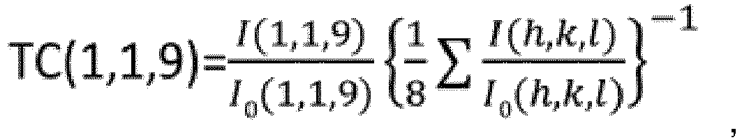 wherein I (h,k,l) denotes a peak intensity for an (h,k,l) plane in X-ray diffraction of the α-type aluminum oxide layer, I0 (h,k,l) denotes a standard diffraction intensity for an (h,k,l) plane which is indicated on a JCPDS Card No. 10-0173 for α-type aluminum oxide, and (h,k,l) refers to eight crystal planes of (0,1,2), (1,0,4), (1,1,0), (1,1,3), (0,2,4), (1,1,6), (2,1,4) and (1,1,9),wherein the coating layer comprises a TiN layer as an outermost layer on a side opposite to the substrate, wherein the average thickness of the TiN layer is from 0.2 µm or more to 1.0 µm or less.
 - The coated cutting tool according to claim 1, wherein, in the α-type aluminum oxide layer, the texture coefficient TC (1,1,9) is from 4.0 or more to 7.2 or less.
- The coated cutting tool according to claim 1 or 2, wherein a residual stress value in a (1,1,6) plane of the α-type aluminum oxide layer is, in at least part thereof, from -300 MPa or higher to 300 MPa or lower.
- The coated cutting tool according to any one of claims 1 to 3, wherein an average particle size of the α-type aluminum oxide layer is from 0.1 µm or more to 3.0 µm or less.
- The coated cutting tool according to any one of claims 1 to 4, wherein an average thickness of the α-type aluminum oxide layer is from 1.0 µm or more to 15.0 µm or less.
- The coated cutting tool according to any one of claims 1 to 5, wherein an average thickness of the TiCN layer is from 2.0 µm or more to 20.0 µm or less.
- The coated cutting tool according to any one of claims 1 to 6, wherein an average thickness of the coating layer is from 3.0 µm or more to 30.0 µm or less.
- The coated cutting tool according to any one of claims 1 to 7, wherein the substrate is comprised of any of a cemented carbide, cermet, ceramics and a sintered body containing cubic boron nitride.
Applications Claiming Priority (1)
| Application Number | Priority Date | Filing Date | Title |
|---|---|---|---|
| JP2016216462A JP6210347B1 (en) | 2016-11-04 | 2016-11-04 | Coated cutting tool |
Publications (3)
| Publication Number | Publication Date |
|---|---|
| EP3318661A1 EP3318661A1 (en) | 2018-05-09 |
| EP3318661B1 EP3318661B1 (en) | 2019-06-26 |
| EP3318661B2 true EP3318661B2 (en) | 2022-10-12 |
Family
ID=60040401
Family Applications (1)
| Application Number | Title | Priority Date | Filing Date |
|---|---|---|---|
| EP17199943.6A Active EP3318661B2 (en) | 2016-11-04 | 2017-11-03 | Coated cutting tool |
Country Status (4)
| Country | Link |
|---|---|
| US (1) | US10072332B2 (en) |
| EP (1) | EP3318661B2 (en) |
| JP (1) | JP6210347B1 (en) |
| CN (1) | CN108018537B (en) |
Families Citing this family (4)
| Publication number | Priority date | Publication date | Assignee | Title |
|---|---|---|---|---|
| JP6955707B2 (en) * | 2016-10-25 | 2021-10-27 | 株式会社タンガロイ | Cover cutting tool |
| JP6210347B1 (en) | 2016-11-04 | 2017-10-11 | 株式会社タンガロイ | Coated cutting tool |
| US11020803B2 (en) * | 2016-11-14 | 2021-06-01 | Tungaloy Corporation | Coated cutting tool |
| BR112020026714B1 (en) * | 2018-06-29 | 2024-01-30 | Ab Sandvik Coromant | METHOD OF TREATMENT OF A CUTTING TOOL AND CUTTING TOOL FOR A METAL CUTTING APPLICATION |
Citations (1)
| Publication number | Priority date | Publication date | Assignee | Title |
|---|---|---|---|---|
| JP2005264194A (en) † | 2004-03-17 | 2005-09-29 | Hitachi Tool Engineering Ltd | alpha-TYPE ALUMINUM OXIDE COATED MEMBER |
Family Cites Families (22)
| Publication number | Priority date | Publication date | Assignee | Title |
|---|---|---|---|---|
| SE502223C2 (en) * | 1994-01-14 | 1995-09-18 | Sandvik Ab | Methods and articles when coating a cutting tool with an alumina layer |
| SE529051C2 (en) | 2005-09-27 | 2007-04-17 | Seco Tools Ab | Cutting tool inserts coated with alumina |
| KR101104493B1 (en) | 2009-06-17 | 2012-01-12 | 한국야금 주식회사 | Coating materials for a cutting tool or an abrasion resistance tool |
| CN102612417A (en) * | 2009-11-06 | 2012-07-25 | 株式会社图格莱 | Coated tool |
| KR101381903B1 (en) | 2011-03-10 | 2014-04-10 | 주식회사 엘지생활건강 | Antibacterial or preservative composition containing 3-butoxy-1,2-propanediol |
| KR101297298B1 (en) * | 2011-06-03 | 2013-08-16 | 한국야금 주식회사 | Coated layer for cutting tools |
| DE102011053705A1 (en) * | 2011-09-16 | 2013-03-21 | Walter Ag | Cutting insert and method for its production |
| EP2604720A1 (en) * | 2011-12-14 | 2013-06-19 | Sandvik Intellectual Property Ab | Coated cutting tool and method of manufacturing the same |
| JP5757232B2 (en) | 2011-12-26 | 2015-07-29 | 三菱マテリアル株式会社 | Surface coated cutting tool with excellent chipping resistance and wear resistance due to hard coating layer |
| KR20140001694A (en) | 2012-06-28 | 2014-01-07 | 대구텍 유한회사 | Cutting insert |
| ES2570537T3 (en) * | 2013-06-27 | 2016-05-18 | Sandvik Intellectual Property | Coated cutting tool |
| CN105517738B (en) * | 2013-08-27 | 2017-11-10 | 京瓷株式会社 | coated tool |
| WO2015068792A1 (en) | 2013-11-08 | 2015-05-14 | 株式会社タンガロイ | Coated cutting tool |
| EP3085478B1 (en) * | 2013-12-17 | 2019-04-10 | Kyocera Corporation | Coated tool |
| RU2675190C2 (en) * | 2014-01-30 | 2018-12-17 | Сандвик Интеллекчуал Проперти Аб | Alumina-coated cutting tool |
| EP3000913B1 (en) * | 2014-09-26 | 2020-07-29 | Walter Ag | Coated cutting tool insert with MT-CVD TiCN on TiAI(C,N) |
| RU2704949C2 (en) * | 2014-12-19 | 2019-10-31 | Сандвик Интеллекчуал Проперти Аб | Cvd coated cutting tool |
| WO2017009928A1 (en) | 2015-07-13 | 2017-01-19 | 住友電工ハードメタル株式会社 | Surface-coated cutting tool |
| KR101902051B1 (en) | 2015-08-04 | 2018-09-27 | 대구텍 유한회사 | Cutting insert |
| KR102216097B1 (en) * | 2015-08-28 | 2021-02-15 | 스미또모 덴꼬오 하드메탈 가부시끼가이샤 | Surface-coated cutting tool and method of manufacturing the same |
| JP6210347B1 (en) | 2016-11-04 | 2017-10-11 | 株式会社タンガロイ | Coated cutting tool |
| US11020803B2 (en) * | 2016-11-14 | 2021-06-01 | Tungaloy Corporation | Coated cutting tool |
-
2016
- 2016-11-04 JP JP2016216462A patent/JP6210347B1/en active Active
-
2017
- 2017-10-25 CN CN201711006123.6A patent/CN108018537B/en active Active
- 2017-10-30 US US15/797,762 patent/US10072332B2/en active Active
- 2017-11-03 EP EP17199943.6A patent/EP3318661B2/en active Active
Patent Citations (1)
| Publication number | Priority date | Publication date | Assignee | Title |
|---|---|---|---|---|
| JP2005264194A (en) † | 2004-03-17 | 2005-09-29 | Hitachi Tool Engineering Ltd | alpha-TYPE ALUMINUM OXIDE COATED MEMBER |
Also Published As
| Publication number | Publication date |
|---|---|
| JP2018069434A (en) | 2018-05-10 |
| US10072332B2 (en) | 2018-09-11 |
| CN108018537A (en) | 2018-05-11 |
| EP3318661A1 (en) | 2018-05-09 |
| CN108018537B (en) | 2020-11-06 |
| US20180127874A1 (en) | 2018-05-10 |
| JP6210347B1 (en) | 2017-10-11 |
| EP3318661B1 (en) | 2019-06-26 |
Similar Documents
| Publication | Publication Date | Title |
|---|---|---|
| US10722948B2 (en) | Coated cutting tool | |
| US10695841B2 (en) | Coated cutting tool | |
| EP3533544B1 (en) | Coated cutting tool | |
| EP3318661B2 (en) | Coated cutting tool | |
| US11318539B2 (en) | Coated cutting tool | |
| US11020803B2 (en) | Coated cutting tool | |
| EP3315632B1 (en) | Coated cutting tool | |
| EP3312303B1 (en) | Coated cutting tool | |
| EP3318657A1 (en) | Coated cutting tool | |
| EP3542935B1 (en) | Coated cutting tool | |
| US10946454B2 (en) | Coated cutting tool | |
| EP3530387B1 (en) | Coated cutting tool |
Legal Events
| Date | Code | Title | Description |
|---|---|---|---|
| PUAI | Public reference made under article 153(3) epc to a published international application that has entered the european phase |
Free format text: ORIGINAL CODE: 0009012 |
|
| STAA | Information on the status of an ep patent application or granted ep patent |
Free format text: STATUS: REQUEST FOR EXAMINATION WAS MADE |
|
| 17P | Request for examination filed |
Effective date: 20171204 |
|
| AK | Designated contracting states |
Kind code of ref document: A1 Designated state(s): AL AT BE BG CH CY CZ DE DK EE ES FI FR GB GR HR HU IE IS IT LI LT LU LV MC MK MT NL NO PL PT RO RS SE SI SK SM TR |
|
| AX | Request for extension of the european patent |
Extension state: BA ME |
|
| RIC1 | Information provided on ipc code assigned before grant |
Ipc: C23C 16/34 20060101ALI20181126BHEP Ipc: C23C 28/04 20060101AFI20181126BHEP Ipc: C23C 16/40 20060101ALI20181126BHEP Ipc: B23B 27/14 20060101ALI20181126BHEP Ipc: C23C 16/36 20060101ALI20181126BHEP |
|
| GRAP | Despatch of communication of intention to grant a patent |
Free format text: ORIGINAL CODE: EPIDOSNIGR1 |
|
| STAA | Information on the status of an ep patent application or granted ep patent |
Free format text: STATUS: GRANT OF PATENT IS INTENDED |
|
| INTG | Intention to grant announced |
Effective date: 20190107 |
|
| GRAS | Grant fee paid |
Free format text: ORIGINAL CODE: EPIDOSNIGR3 |
|
| GRAA | (expected) grant |
Free format text: ORIGINAL CODE: 0009210 |
|
| STAA | Information on the status of an ep patent application or granted ep patent |
Free format text: STATUS: THE PATENT HAS BEEN GRANTED |
|
| AK | Designated contracting states |
Kind code of ref document: B1 Designated state(s): AL AT BE BG CH CY CZ DE DK EE ES FI FR GB GR HR HU IE IS IT LI LT LU LV MC MK MT NL NO PL PT RO RS SE SI SK SM TR |
|
| REG | Reference to a national code |
Ref country code: GB Ref legal event code: FG4D |
|
| REG | Reference to a national code |
Ref country code: CH Ref legal event code: EP |
|
| REG | Reference to a national code |
Ref country code: AT Ref legal event code: REF Ref document number: 1148368 Country of ref document: AT Kind code of ref document: T Effective date: 20190715 |
|
| REG | Reference to a national code |
Ref country code: DE Ref legal event code: R096 Ref document number: 602017004838 Country of ref document: DE |
|
| REG | Reference to a national code |
Ref country code: IE Ref legal event code: FG4D |
|
| REG | Reference to a national code |
Ref country code: NL Ref legal event code: MP Effective date: 20190626 |
|
| PG25 | Lapsed in a contracting state [announced via postgrant information from national office to epo] |
Ref country code: HR Free format text: LAPSE BECAUSE OF FAILURE TO SUBMIT A TRANSLATION OF THE DESCRIPTION OR TO PAY THE FEE WITHIN THE PRESCRIBED TIME-LIMIT Effective date: 20190626 Ref country code: SE Free format text: LAPSE BECAUSE OF FAILURE TO SUBMIT A TRANSLATION OF THE DESCRIPTION OR TO PAY THE FEE WITHIN THE PRESCRIBED TIME-LIMIT Effective date: 20190626 Ref country code: NO Free format text: LAPSE BECAUSE OF FAILURE TO SUBMIT A TRANSLATION OF THE DESCRIPTION OR TO PAY THE FEE WITHIN THE PRESCRIBED TIME-LIMIT Effective date: 20190926 Ref country code: AL Free format text: LAPSE BECAUSE OF FAILURE TO SUBMIT A TRANSLATION OF THE DESCRIPTION OR TO PAY THE FEE WITHIN THE PRESCRIBED TIME-LIMIT Effective date: 20190626 Ref country code: FI Free format text: LAPSE BECAUSE OF FAILURE TO SUBMIT A TRANSLATION OF THE DESCRIPTION OR TO PAY THE FEE WITHIN THE PRESCRIBED TIME-LIMIT Effective date: 20190626 Ref country code: LT Free format text: LAPSE BECAUSE OF FAILURE TO SUBMIT A TRANSLATION OF THE DESCRIPTION OR TO PAY THE FEE WITHIN THE PRESCRIBED TIME-LIMIT Effective date: 20190626 |
|
| REG | Reference to a national code |
Ref country code: LT Ref legal event code: MG4D |
|
| PG25 | Lapsed in a contracting state [announced via postgrant information from national office to epo] |
Ref country code: BG Free format text: LAPSE BECAUSE OF FAILURE TO SUBMIT A TRANSLATION OF THE DESCRIPTION OR TO PAY THE FEE WITHIN THE PRESCRIBED TIME-LIMIT Effective date: 20190926 Ref country code: GR Free format text: LAPSE BECAUSE OF FAILURE TO SUBMIT A TRANSLATION OF THE DESCRIPTION OR TO PAY THE FEE WITHIN THE PRESCRIBED TIME-LIMIT Effective date: 20190927 Ref country code: RS Free format text: LAPSE BECAUSE OF FAILURE TO SUBMIT A TRANSLATION OF THE DESCRIPTION OR TO PAY THE FEE WITHIN THE PRESCRIBED TIME-LIMIT Effective date: 20190626 Ref country code: LV Free format text: LAPSE BECAUSE OF FAILURE TO SUBMIT A TRANSLATION OF THE DESCRIPTION OR TO PAY THE FEE WITHIN THE PRESCRIBED TIME-LIMIT Effective date: 20190626 |
|
| REG | Reference to a national code |
Ref country code: AT Ref legal event code: MK05 Ref document number: 1148368 Country of ref document: AT Kind code of ref document: T Effective date: 20190626 |
|
| PG25 | Lapsed in a contracting state [announced via postgrant information from national office to epo] |
Ref country code: NL Free format text: LAPSE BECAUSE OF FAILURE TO SUBMIT A TRANSLATION OF THE DESCRIPTION OR TO PAY THE FEE WITHIN THE PRESCRIBED TIME-LIMIT Effective date: 20190626 Ref country code: AT Free format text: LAPSE BECAUSE OF FAILURE TO SUBMIT A TRANSLATION OF THE DESCRIPTION OR TO PAY THE FEE WITHIN THE PRESCRIBED TIME-LIMIT Effective date: 20190626 Ref country code: EE Free format text: LAPSE BECAUSE OF FAILURE TO SUBMIT A TRANSLATION OF THE DESCRIPTION OR TO PAY THE FEE WITHIN THE PRESCRIBED TIME-LIMIT Effective date: 20190626 Ref country code: RO Free format text: LAPSE BECAUSE OF FAILURE TO SUBMIT A TRANSLATION OF THE DESCRIPTION OR TO PAY THE FEE WITHIN THE PRESCRIBED TIME-LIMIT Effective date: 20190626 Ref country code: CZ Free format text: LAPSE BECAUSE OF FAILURE TO SUBMIT A TRANSLATION OF THE DESCRIPTION OR TO PAY THE FEE WITHIN THE PRESCRIBED TIME-LIMIT Effective date: 20190626 Ref country code: SK Free format text: LAPSE BECAUSE OF FAILURE TO SUBMIT A TRANSLATION OF THE DESCRIPTION OR TO PAY THE FEE WITHIN THE PRESCRIBED TIME-LIMIT Effective date: 20190626 Ref country code: PT Free format text: LAPSE BECAUSE OF FAILURE TO SUBMIT A TRANSLATION OF THE DESCRIPTION OR TO PAY THE FEE WITHIN THE PRESCRIBED TIME-LIMIT Effective date: 20191028 |
|
| PG25 | Lapsed in a contracting state [announced via postgrant information from national office to epo] |
Ref country code: IS Free format text: LAPSE BECAUSE OF FAILURE TO SUBMIT A TRANSLATION OF THE DESCRIPTION OR TO PAY THE FEE WITHIN THE PRESCRIBED TIME-LIMIT Effective date: 20191026 Ref country code: SM Free format text: LAPSE BECAUSE OF FAILURE TO SUBMIT A TRANSLATION OF THE DESCRIPTION OR TO PAY THE FEE WITHIN THE PRESCRIBED TIME-LIMIT Effective date: 20190626 Ref country code: IT Free format text: LAPSE BECAUSE OF FAILURE TO SUBMIT A TRANSLATION OF THE DESCRIPTION OR TO PAY THE FEE WITHIN THE PRESCRIBED TIME-LIMIT Effective date: 20190626 Ref country code: ES Free format text: LAPSE BECAUSE OF FAILURE TO SUBMIT A TRANSLATION OF THE DESCRIPTION OR TO PAY THE FEE WITHIN THE PRESCRIBED TIME-LIMIT Effective date: 20190626 |
|
| REG | Reference to a national code |
Ref country code: DE Ref legal event code: R026 Ref document number: 602017004838 Country of ref document: DE |
|
| PG25 | Lapsed in a contracting state [announced via postgrant information from national office to epo] |
Ref country code: TR Free format text: LAPSE BECAUSE OF FAILURE TO SUBMIT A TRANSLATION OF THE DESCRIPTION OR TO PAY THE FEE WITHIN THE PRESCRIBED TIME-LIMIT Effective date: 20190626 |
|
| PLBI | Opposition filed |
Free format text: ORIGINAL CODE: 0009260 |
|
| PG25 | Lapsed in a contracting state [announced via postgrant information from national office to epo] |
Ref country code: DK Free format text: LAPSE BECAUSE OF FAILURE TO SUBMIT A TRANSLATION OF THE DESCRIPTION OR TO PAY THE FEE WITHIN THE PRESCRIBED TIME-LIMIT Effective date: 20190626 Ref country code: PL Free format text: LAPSE BECAUSE OF FAILURE TO SUBMIT A TRANSLATION OF THE DESCRIPTION OR TO PAY THE FEE WITHIN THE PRESCRIBED TIME-LIMIT Effective date: 20190626 |
|
| 26 | Opposition filed |
Opponent name: SANDVIK MACHINING SOLUTIONS AB Effective date: 20200326 |
|
| PG25 | Lapsed in a contracting state [announced via postgrant information from national office to epo] |
Ref country code: IS Free format text: LAPSE BECAUSE OF FAILURE TO SUBMIT A TRANSLATION OF THE DESCRIPTION OR TO PAY THE FEE WITHIN THE PRESCRIBED TIME-LIMIT Effective date: 20200320 |
|
| PLAX | Notice of opposition and request to file observation + time limit sent |
Free format text: ORIGINAL CODE: EPIDOSNOBS2 |
|
| PG2D | Information on lapse in contracting state deleted |
Ref country code: IS |
|
| PG25 | Lapsed in a contracting state [announced via postgrant information from national office to epo] |
Ref country code: LU Free format text: LAPSE BECAUSE OF NON-PAYMENT OF DUE FEES Effective date: 20191103 Ref country code: MC Free format text: LAPSE BECAUSE OF FAILURE TO SUBMIT A TRANSLATION OF THE DESCRIPTION OR TO PAY THE FEE WITHIN THE PRESCRIBED TIME-LIMIT Effective date: 20190626 |
|
| REG | Reference to a national code |
Ref country code: BE Ref legal event code: MM Effective date: 20191130 |
|
| PG25 | Lapsed in a contracting state [announced via postgrant information from national office to epo] |
Ref country code: SI Free format text: LAPSE BECAUSE OF FAILURE TO SUBMIT A TRANSLATION OF THE DESCRIPTION OR TO PAY THE FEE WITHIN THE PRESCRIBED TIME-LIMIT Effective date: 20190626 |
|
| PLBB | Reply of patent proprietor to notice(s) of opposition received |
Free format text: ORIGINAL CODE: EPIDOSNOBS3 |
|
| PG25 | Lapsed in a contracting state [announced via postgrant information from national office to epo] |
Ref country code: IE Free format text: LAPSE BECAUSE OF NON-PAYMENT OF DUE FEES Effective date: 20191103 Ref country code: FR Free format text: LAPSE BECAUSE OF NON-PAYMENT OF DUE FEES Effective date: 20191130 |
|
| PG25 | Lapsed in a contracting state [announced via postgrant information from national office to epo] |
Ref country code: BE Free format text: LAPSE BECAUSE OF NON-PAYMENT OF DUE FEES Effective date: 20191130 |
|
| PG25 | Lapsed in a contracting state [announced via postgrant information from national office to epo] |
Ref country code: CY Free format text: LAPSE BECAUSE OF FAILURE TO SUBMIT A TRANSLATION OF THE DESCRIPTION OR TO PAY THE FEE WITHIN THE PRESCRIBED TIME-LIMIT Effective date: 20190626 |
|
| PG25 | Lapsed in a contracting state [announced via postgrant information from national office to epo] |
Ref country code: LI Free format text: LAPSE BECAUSE OF FAILURE TO SUBMIT A TRANSLATION OF THE DESCRIPTION OR TO PAY THE FEE WITHIN THE PRESCRIBED TIME-LIMIT Effective date: 20201130 Ref country code: CH Free format text: LAPSE BECAUSE OF FAILURE TO SUBMIT A TRANSLATION OF THE DESCRIPTION OR TO PAY THE FEE WITHIN THE PRESCRIBED TIME-LIMIT Effective date: 20201130 |
|
| REG | Reference to a national code |
Ref country code: CH Ref legal event code: PL |
|
| PG25 | Lapsed in a contracting state [announced via postgrant information from national office to epo] |
Ref country code: MT Free format text: LAPSE BECAUSE OF FAILURE TO SUBMIT A TRANSLATION OF THE DESCRIPTION OR TO PAY THE FEE WITHIN THE PRESCRIBED TIME-LIMIT Effective date: 20190626 Ref country code: HU Free format text: LAPSE BECAUSE OF FAILURE TO SUBMIT A TRANSLATION OF THE DESCRIPTION OR TO PAY THE FEE WITHIN THE PRESCRIBED TIME-LIMIT; INVALID AB INITIO Effective date: 20171103 |
|
| PLAB | Opposition data, opponent's data or that of the opponent's representative modified |
Free format text: ORIGINAL CODE: 0009299OPPO |
|
| R26 | Opposition filed (corrected) |
Opponent name: SANDVIK MACHINING SOLUTIONS AB Effective date: 20200326 |
|
| PG25 | Lapsed in a contracting state [announced via postgrant information from national office to epo] |
Ref country code: MK Free format text: LAPSE BECAUSE OF FAILURE TO SUBMIT A TRANSLATION OF THE DESCRIPTION OR TO PAY THE FEE WITHIN THE PRESCRIBED TIME-LIMIT Effective date: 20190626 |
|
| GBPC | Gb: european patent ceased through non-payment of renewal fee |
Effective date: 20211103 |
|
| PUAH | Patent maintained in amended form |
Free format text: ORIGINAL CODE: 0009272 |
|
| STAA | Information on the status of an ep patent application or granted ep patent |
Free format text: STATUS: PATENT MAINTAINED AS AMENDED |
|
| 27A | Patent maintained in amended form |
Effective date: 20221012 |
|
| AK | Designated contracting states |
Kind code of ref document: B2 Designated state(s): AL AT BE BG CH CY CZ DE DK EE ES FI FR GB GR HR HU IE IS IT LI LT LU LV MC MK MT NL NO PL PT RO RS SE SI SK SM TR |
|
| REG | Reference to a national code |
Ref country code: DE Ref legal event code: R102 Ref document number: 602017004838 Country of ref document: DE |
|
| PG25 | Lapsed in a contracting state [announced via postgrant information from national office to epo] |
Ref country code: GB Free format text: LAPSE BECAUSE OF NON-PAYMENT OF DUE FEES Effective date: 20211103 |
|
| PGFP | Annual fee paid to national office [announced via postgrant information from national office to epo] |
Ref country code: DE Payment date: 20231121 Year of fee payment: 7 |