WO2018079064A1 - ダンパー - Google Patents
ダンパー Download PDFInfo
- Publication number
- WO2018079064A1 WO2018079064A1 PCT/JP2017/031347 JP2017031347W WO2018079064A1 WO 2018079064 A1 WO2018079064 A1 WO 2018079064A1 JP 2017031347 W JP2017031347 W JP 2017031347W WO 2018079064 A1 WO2018079064 A1 WO 2018079064A1
- Authority
- WO
- WIPO (PCT)
- Prior art keywords
- housing
- seal member
- piston
- wall
- slider
- Prior art date
- Legal status (The legal status is an assumption and is not a legal conclusion. Google has not performed a legal analysis and makes no representation as to the accuracy of the status listed.)
- Ceased
Links
Images




Classifications
-
- F—MECHANICAL ENGINEERING; LIGHTING; HEATING; WEAPONS; BLASTING
- F16—ENGINEERING ELEMENTS AND UNITS; GENERAL MEASURES FOR PRODUCING AND MAINTAINING EFFECTIVE FUNCTIONING OF MACHINES OR INSTALLATIONS; THERMAL INSULATION IN GENERAL
- F16F—SPRINGS; SHOCK-ABSORBERS; MEANS FOR DAMPING VIBRATION
- F16F7/00—Vibration-dampers; Shock-absorbers
- F16F7/08—Vibration-dampers; Shock-absorbers with friction surfaces rectilinearly movable along each other
- F16F7/09—Vibration-dampers; Shock-absorbers with friction surfaces rectilinearly movable along each other in dampers of the cylinder-and-piston type
-
- F—MECHANICAL ENGINEERING; LIGHTING; HEATING; WEAPONS; BLASTING
- F16—ENGINEERING ELEMENTS AND UNITS; GENERAL MEASURES FOR PRODUCING AND MAINTAINING EFFECTIVE FUNCTIONING OF MACHINES OR INSTALLATIONS; THERMAL INSULATION IN GENERAL
- F16F—SPRINGS; SHOCK-ABSORBERS; MEANS FOR DAMPING VIBRATION
- F16F9/00—Springs, vibration-dampers, shock-absorbers, or similarly-constructed movement-dampers using a fluid or the equivalent as damping medium
-
- F—MECHANICAL ENGINEERING; LIGHTING; HEATING; WEAPONS; BLASTING
- F16—ENGINEERING ELEMENTS AND UNITS; GENERAL MEASURES FOR PRODUCING AND MAINTAINING EFFECTIVE FUNCTIONING OF MACHINES OR INSTALLATIONS; THERMAL INSULATION IN GENERAL
- F16F—SPRINGS; SHOCK-ABSORBERS; MEANS FOR DAMPING VIBRATION
- F16F9/00—Springs, vibration-dampers, shock-absorbers, or similarly-constructed movement-dampers using a fluid or the equivalent as damping medium
- F16F9/02—Springs, vibration-dampers, shock-absorbers, or similarly-constructed movement-dampers using a fluid or the equivalent as damping medium using gas only or vacuum
-
- F—MECHANICAL ENGINEERING; LIGHTING; HEATING; WEAPONS; BLASTING
- F16—ENGINEERING ELEMENTS AND UNITS; GENERAL MEASURES FOR PRODUCING AND MAINTAINING EFFECTIVE FUNCTIONING OF MACHINES OR INSTALLATIONS; THERMAL INSULATION IN GENERAL
- F16F—SPRINGS; SHOCK-ABSORBERS; MEANS FOR DAMPING VIBRATION
- F16F9/00—Springs, vibration-dampers, shock-absorbers, or similarly-constructed movement-dampers using a fluid or the equivalent as damping medium
- F16F9/02—Springs, vibration-dampers, shock-absorbers, or similarly-constructed movement-dampers using a fluid or the equivalent as damping medium using gas only or vacuum
- F16F9/0209—Telescopic
- F16F9/0218—Mono-tubular units
-
- F—MECHANICAL ENGINEERING; LIGHTING; HEATING; WEAPONS; BLASTING
- F16—ENGINEERING ELEMENTS AND UNITS; GENERAL MEASURES FOR PRODUCING AND MAINTAINING EFFECTIVE FUNCTIONING OF MACHINES OR INSTALLATIONS; THERMAL INSULATION IN GENERAL
- F16F—SPRINGS; SHOCK-ABSORBERS; MEANS FOR DAMPING VIBRATION
- F16F9/00—Springs, vibration-dampers, shock-absorbers, or similarly-constructed movement-dampers using a fluid or the equivalent as damping medium
- F16F9/32—Details
- F16F9/3207—Constructional features
- F16F9/3214—Constructional features of pistons
-
- F—MECHANICAL ENGINEERING; LIGHTING; HEATING; WEAPONS; BLASTING
- F16—ENGINEERING ELEMENTS AND UNITS; GENERAL MEASURES FOR PRODUCING AND MAINTAINING EFFECTIVE FUNCTIONING OF MACHINES OR INSTALLATIONS; THERMAL INSULATION IN GENERAL
- F16F—SPRINGS; SHOCK-ABSORBERS; MEANS FOR DAMPING VIBRATION
- F16F9/00—Springs, vibration-dampers, shock-absorbers, or similarly-constructed movement-dampers using a fluid or the equivalent as damping medium
- F16F9/32—Details
- F16F9/36—Special sealings, including sealings or guides for piston-rods
-
- F—MECHANICAL ENGINEERING; LIGHTING; HEATING; WEAPONS; BLASTING
- F16—ENGINEERING ELEMENTS AND UNITS; GENERAL MEASURES FOR PRODUCING AND MAINTAINING EFFECTIVE FUNCTIONING OF MACHINES OR INSTALLATIONS; THERMAL INSULATION IN GENERAL
- F16F—SPRINGS; SHOCK-ABSORBERS; MEANS FOR DAMPING VIBRATION
- F16F9/00—Springs, vibration-dampers, shock-absorbers, or similarly-constructed movement-dampers using a fluid or the equivalent as damping medium
- F16F9/32—Details
- F16F9/36—Special sealings, including sealings or guides for piston-rods
- F16F9/368—Sealings in pistons
-
- F—MECHANICAL ENGINEERING; LIGHTING; HEATING; WEAPONS; BLASTING
- F16—ENGINEERING ELEMENTS AND UNITS; GENERAL MEASURES FOR PRODUCING AND MAINTAINING EFFECTIVE FUNCTIONING OF MACHINES OR INSTALLATIONS; THERMAL INSULATION IN GENERAL
- F16F—SPRINGS; SHOCK-ABSORBERS; MEANS FOR DAMPING VIBRATION
- F16F9/00—Springs, vibration-dampers, shock-absorbers, or similarly-constructed movement-dampers using a fluid or the equivalent as damping medium
- F16F9/32—Details
- F16F9/50—Special means providing automatic damping adjustment, i.e. self-adjustment of damping by particular sliding movements of a valve element, other than flexions or displacement of valve discs; Special means providing self-adjustment of spring characteristics
- F16F9/512—Means responsive to load action, i.e. static load on the damper or dynamic fluid pressure changes in the damper, e.g. due to changes in velocity
-
- F—MECHANICAL ENGINEERING; LIGHTING; HEATING; WEAPONS; BLASTING
- F16—ENGINEERING ELEMENTS AND UNITS; GENERAL MEASURES FOR PRODUCING AND MAINTAINING EFFECTIVE FUNCTIONING OF MACHINES OR INSTALLATIONS; THERMAL INSULATION IN GENERAL
- F16F—SPRINGS; SHOCK-ABSORBERS; MEANS FOR DAMPING VIBRATION
- F16F9/00—Springs, vibration-dampers, shock-absorbers, or similarly-constructed movement-dampers using a fluid or the equivalent as damping medium
- F16F9/32—Details
- F16F9/50—Special means providing automatic damping adjustment, i.e. self-adjustment of damping by particular sliding movements of a valve element, other than flexions or displacement of valve discs; Special means providing self-adjustment of spring characteristics
- F16F9/516—Special means providing automatic damping adjustment, i.e. self-adjustment of damping by particular sliding movements of a valve element, other than flexions or displacement of valve discs; Special means providing self-adjustment of spring characteristics resulting in the damping effects during contraction being different from the damping effects during extension, i.e. responsive to the direction of movement
-
- F—MECHANICAL ENGINEERING; LIGHTING; HEATING; WEAPONS; BLASTING
- F16—ENGINEERING ELEMENTS AND UNITS; GENERAL MEASURES FOR PRODUCING AND MAINTAINING EFFECTIVE FUNCTIONING OF MACHINES OR INSTALLATIONS; THERMAL INSULATION IN GENERAL
- F16J—PISTONS; CYLINDERS; SEALINGS
- F16J15/00—Sealings
- F16J15/16—Sealings between relatively-moving surfaces
- F16J15/32—Sealings between relatively-moving surfaces with elastic sealings, e.g. O-rings
- F16J15/3204—Sealings between relatively-moving surfaces with elastic sealings, e.g. O-rings with at least one lip
-
- F—MECHANICAL ENGINEERING; LIGHTING; HEATING; WEAPONS; BLASTING
- F16—ENGINEERING ELEMENTS AND UNITS; GENERAL MEASURES FOR PRODUCING AND MAINTAINING EFFECTIVE FUNCTIONING OF MACHINES OR INSTALLATIONS; THERMAL INSULATION IN GENERAL
- F16J—PISTONS; CYLINDERS; SEALINGS
- F16J15/00—Sealings
- F16J15/16—Sealings between relatively-moving surfaces
- F16J15/32—Sealings between relatively-moving surfaces with elastic sealings, e.g. O-rings
- F16J15/3204—Sealings between relatively-moving surfaces with elastic sealings, e.g. O-rings with at least one lip
- F16J15/3232—Sealings between relatively-moving surfaces with elastic sealings, e.g. O-rings with at least one lip having two or more lips
- F16J15/3236—Sealings between relatively-moving surfaces with elastic sealings, e.g. O-rings with at least one lip having two or more lips with at least one lip for each surface, e.g. U-cup packings
-
- F—MECHANICAL ENGINEERING; LIGHTING; HEATING; WEAPONS; BLASTING
- F16—ENGINEERING ELEMENTS AND UNITS; GENERAL MEASURES FOR PRODUCING AND MAINTAINING EFFECTIVE FUNCTIONING OF MACHINES OR INSTALLATIONS; THERMAL INSULATION IN GENERAL
- F16J—PISTONS; CYLINDERS; SEALINGS
- F16J15/00—Sealings
- F16J15/16—Sealings between relatively-moving surfaces
- F16J15/32—Sealings between relatively-moving surfaces with elastic sealings, e.g. O-rings
- F16J15/3248—Sealings between relatively-moving surfaces with elastic sealings, e.g. O-rings provided with casings or supports
-
- F—MECHANICAL ENGINEERING; LIGHTING; HEATING; WEAPONS; BLASTING
- F16—ENGINEERING ELEMENTS AND UNITS; GENERAL MEASURES FOR PRODUCING AND MAINTAINING EFFECTIVE FUNCTIONING OF MACHINES OR INSTALLATIONS; THERMAL INSULATION IN GENERAL
- F16J—PISTONS; CYLINDERS; SEALINGS
- F16J15/00—Sealings
- F16J15/56—Other sealings for reciprocating rods
-
- F—MECHANICAL ENGINEERING; LIGHTING; HEATING; WEAPONS; BLASTING
- F16—ENGINEERING ELEMENTS AND UNITS; GENERAL MEASURES FOR PRODUCING AND MAINTAINING EFFECTIVE FUNCTIONING OF MACHINES OR INSTALLATIONS; THERMAL INSULATION IN GENERAL
- F16F—SPRINGS; SHOCK-ABSORBERS; MEANS FOR DAMPING VIBRATION
- F16F2222/00—Special physical effects, e.g. nature of damping effects
- F16F2222/04—Friction
-
- F—MECHANICAL ENGINEERING; LIGHTING; HEATING; WEAPONS; BLASTING
- F16—ENGINEERING ELEMENTS AND UNITS; GENERAL MEASURES FOR PRODUCING AND MAINTAINING EFFECTIVE FUNCTIONING OF MACHINES OR INSTALLATIONS; THERMAL INSULATION IN GENERAL
- F16F—SPRINGS; SHOCK-ABSORBERS; MEANS FOR DAMPING VIBRATION
- F16F2222/00—Special physical effects, e.g. nature of damping effects
- F16F2222/12—Fluid damping
-
- F—MECHANICAL ENGINEERING; LIGHTING; HEATING; WEAPONS; BLASTING
- F16—ENGINEERING ELEMENTS AND UNITS; GENERAL MEASURES FOR PRODUCING AND MAINTAINING EFFECTIVE FUNCTIONING OF MACHINES OR INSTALLATIONS; THERMAL INSULATION IN GENERAL
- F16F—SPRINGS; SHOCK-ABSORBERS; MEANS FOR DAMPING VIBRATION
- F16F2224/00—Materials; Material properties
- F16F2224/02—Materials; Material properties solids
-
- F—MECHANICAL ENGINEERING; LIGHTING; HEATING; WEAPONS; BLASTING
- F16—ENGINEERING ELEMENTS AND UNITS; GENERAL MEASURES FOR PRODUCING AND MAINTAINING EFFECTIVE FUNCTIONING OF MACHINES OR INSTALLATIONS; THERMAL INSULATION IN GENERAL
- F16F—SPRINGS; SHOCK-ABSORBERS; MEANS FOR DAMPING VIBRATION
- F16F2224/00—Materials; Material properties
- F16F2224/02—Materials; Material properties solids
- F16F2224/025—Elastomers
-
- F—MECHANICAL ENGINEERING; LIGHTING; HEATING; WEAPONS; BLASTING
- F16—ENGINEERING ELEMENTS AND UNITS; GENERAL MEASURES FOR PRODUCING AND MAINTAINING EFFECTIVE FUNCTIONING OF MACHINES OR INSTALLATIONS; THERMAL INSULATION IN GENERAL
- F16F—SPRINGS; SHOCK-ABSORBERS; MEANS FOR DAMPING VIBRATION
- F16F2228/00—Functional characteristics, e.g. variability, frequency-dependence
- F16F2228/06—Stiffness
- F16F2228/066—Variable stiffness
-
- F—MECHANICAL ENGINEERING; LIGHTING; HEATING; WEAPONS; BLASTING
- F16—ENGINEERING ELEMENTS AND UNITS; GENERAL MEASURES FOR PRODUCING AND MAINTAINING EFFECTIVE FUNCTIONING OF MACHINES OR INSTALLATIONS; THERMAL INSULATION IN GENERAL
- F16F—SPRINGS; SHOCK-ABSORBERS; MEANS FOR DAMPING VIBRATION
- F16F2230/00—Purpose; Design features
- F16F2230/30—Sealing arrangements
-
- F—MECHANICAL ENGINEERING; LIGHTING; HEATING; WEAPONS; BLASTING
- F16—ENGINEERING ELEMENTS AND UNITS; GENERAL MEASURES FOR PRODUCING AND MAINTAINING EFFECTIVE FUNCTIONING OF MACHINES OR INSTALLATIONS; THERMAL INSULATION IN GENERAL
- F16F—SPRINGS; SHOCK-ABSORBERS; MEANS FOR DAMPING VIBRATION
- F16F2232/00—Nature of movement
- F16F2232/08—Linear
Definitions
- This invention relates to an improvement of a damper.
- the piston includes a seal member for the inner wall of the housing, and a slider that contacts the inner wall of the housing with a predetermined frictional force.
- the slider presses against the seal member, and a portion of the seal member that contacts the inner wall of the housing is deformed toward the outside of the housing.
- the portion of the seal member that contacts the inner wall of the housing when the braking force is generated has a skirt shape and extends toward the forward movement side of the piston.
- a buckling F in which the inner side of the housing H is bent outward may occur.
- Such buckling F is likely to occur when a high load is applied to the piston P, and is also likely to occur when the cross-sectional outline shape of the housing H in a direction perpendicular to the moving direction of the piston P is flattened.
- the sealing performance between the seal member S and the housing H is deteriorated, the ventilation to the chamber C cannot be controlled, and the frictional force of the seal member S to the inner wall of the housing H is also reduced.
- the braking force of the damper is rapidly reduced.
- the object to be braked is moved so as to repeat rapid movement and stop alternately.
- the main problem to be solved by the present invention is that this type of damper is reasonably equipped with a structure that makes it possible to continuously apply a uniform braking force to the object to be braked throughout its movement. It is in point to let you.
- the damper comprises a piston provided with a rod and a housing that houses the piston, and a damper that generates a braking force by the operation of the piston
- the piston is A sealing member for the inner wall of the housing;
- a slider in contact with the inner wall of the housing with a predetermined frictional force, When the braking force is generated, the slider is pressed against the seal member, and a portion of the seal member that is in contact with the inner wall of the housing is deformed toward the outside of the housing.
- a deformation control unit that suppresses deformation of the seal member to the inside of the housing is provided inside a portion of the seal member that contacts the inner wall of the housing.
- the deformation suppressing portion when the braking force is generated, can suppress inward deformation of a portion of the seal member that is in contact with the inner wall of the housing. It is possible to continue to apply a uniform braking force.
- the deformation suppression unit is in contact with at least the position of the seal member in contact with the inner wall of the housing in the center in the direction along the direction of movement of the piston during the deformation so as to suppress the deformation. This is one aspect of the present invention.
- the deformation suppressing portion is provided integrally with the slider. Further, it is an aspect of the present invention that the deformation suppressing portion is provided integrally with the seal member.
- one aspect of the present invention is to flatten the cross-sectional outline of the housing in a direction perpendicular to the moving direction of the piston.
- this type of damper can be rationally provided with a structure that allows a braking force to be continuously applied to the braking target throughout the entire movement.
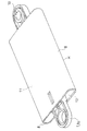
- FIG. 1 is a perspective view of a damper according to an embodiment of the present invention.
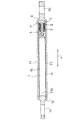
- FIG. 2 is a cross-sectional configuration diagram of the damper.
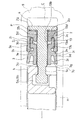
- FIG. 3 is an enlarged cross-sectional configuration view of a main part of the damper, and shows a state when the piston moves forward.
- FIG. 4 is an enlarged cross-sectional configuration view of a main part of the damper, and shows a state when the piston moves forward.
- FIG. 5 is an enlarged cross-sectional configuration view of a main part of the damper, and shows a state when the piston moves backward.
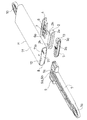
- FIG. 6 is an exploded perspective view of the damper.
- FIG. 7 is a perspective view of a head part constituting the piston of the damper.
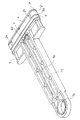
- FIG. 8 is a perspective view of the piston of the damper.
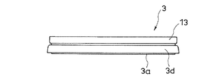
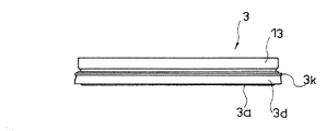
- FIG. 9 is a side view of a slider constituting the piston of the damper.
- FIG. 11 is a cross-sectional view of a slider constituting the piston of the damper.
- FIG. 11 is a side view of a modified example of the slider.
- FIG. 12 is a cross-sectional view of a slider according to the modified example of FIG.
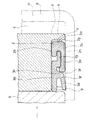
- FIG. 13 is a cross-sectional configuration diagram illustrating a modified example in which the deformation control unit is provided on the seal member side.
- FIG. 14 is a cross-sectional configuration diagram illustrating a problem occurrence state in the conventional example.
- the damper according to this embodiment generates a braking force for the operation of the piston P constituting the damper, that is, the movement or relative movement of the piston P, and is typically a braking target.
- the braking force is applied to the movement of the braking object, and the movement of the braking object is slow, high-grade, It is used in order not to make things moderate or excessive.
- the damper includes a piston P having a rod 1 and a housing H in which the piston P is accommodated.
- a damper links either one of the rod 1 and the housing H directly or indirectly to the braking object side, and directly or indirectly connects the other of these to the side that movably supports the braking object. By linking, it is combined with an article having such a braking object.
- the housing H has a cylindrical shape with one end open and the other end closed.
- the housing H has a flat cylindrical shape with a significantly reduced thickness, as shown in FIG. More specifically, in the illustrated example, the housing H has a substantially rectangular cross section perpendicular to the cylinder axis.
- the side wall 8 constituting the thickness side of the housing H has a curved shape with the outer side of the housing H being the curved outer side.
- a bracket portion 10 for the linkage is formed outside the closed end 9 of the housing H.
- the rod 1 has a long rod shape in the moving direction of the piston P as shown in FIGS.
- a bracket portion 1a for the linkage is formed at one end of the rod 1 located outside the housing H.
- Reference numeral 1b in the drawing denotes a long hole formed in the middle of the rod in the width direction along the length direction of the rod, and as shown in FIG.
- the retaining piece 11a formed on one side of the side wall 11 constituting the width side is bent, and the leading end side of the retaining piece 11a is engaged with the other side wall 11 constituting the width side of the housing H through the elongated hole 1b. This prevents the rod 1 from coming out of the housing H.
- the piston P includes a seal member 2 with respect to the inner wall of the housing H, and a slider 3 that is slidable in the moving direction of the piston P and that contacts the inner wall of the housing H with a predetermined frictional force.
- the piston P includes a first flange 4 that faces the closed end 9 of the housing H, and a second flange 5 that holds the seal member 2 and the slider 3 between the first flange 4. ing.
- the second flange 5 is located behind the first flange 4, that is, on the open end 12 side of the housing H. Both the first flange 4 and the second flange 5 have the same cross-sectional outline shape in the direction orthogonal to the moving direction x of the piston P shown in FIG. 2, that is, the direction along the cylinder axis of the housing H.
- the piston P is guided by the inner wall of the housing H so as to reciprocate in the direction along the cylindrical axis of the housing H.
- the second flange 5 is formed at the other end of the rod 1 as shown in FIG.
- the first flange 4 is formed on the head part 6 which is separate from the rod 1.
- the head part 6 has a plate-like body portion 6 a whose plate surface faces the side wall on the width side of the housing H.
- the first flange 4 with the flange end positioned on the outer side of the outer surface of the barrel portion 6a at each position around the barrel portion 6a is integrally formed on the side of the barrel portion 6a facing the closed end 9 of the housing H. Is formed.
- an end portion of the trunk portion 6a directed to the open end 12 of the housing H, which is located on the cylinder axis of the housing H, includes a head portion 6c and a neck portion 6d, and a neck portion.
- a male joint portion 6b integrated with the trunk portion 6a via the portion 6d is formed.
- the first flange 5 b that receives and holds the head 6 c of the male joint portion 6 b and the male joint are located at a position on the cylindrical axis of the housing H in the second flange 5.
- a female joint portion 5a is formed which receives and holds the neck portion 6c of the portion 6b and includes a second recess 5c opened outward at the end of the second flange 5 facing the closed end 9 of the housing H. ing.
- the seal member 2 and the slider 3 each having a flat ring shape are combined with the head part 6 so as to surround the body portion 6a of the head part 6, and then the male part of the head part 6 is used.
- a piston P configured to hold the seal member 2 and the slider 3 between the first flange 4 and the second flange 5 is formed. It has become.
- the seal member 2 is typically made of rubber or plastic with rubber-like elasticity, and has a flat ring shape. By inserting the body portion 6a of the head part 6 into the seal member 2 from the male joint portion 6b side, the head part 6 and the seal member 2 are combined.
- the seal member 2 includes a front end portion 2 a for the first flange 4, an inner surface portion 2 b for the outer surface of the body portion 6 a of the head part 6, and an outer surface portion for the inner wall of the housing H. 2c. Further, on the side of the seal member 2 facing the open end 12 of the housing H, a circumferential groove 2d is formed between the inner surface portion 2b and the outer surface portion 2c. The outer surface 2c side across the circumferential groove 2d extends toward the open end 12 side of the housing H over the entire circumferential direction of the seal member 2 and exhibits a circumferential belt shape surrounding the cylindrical shaft of the housing H. Yes.
- the seal member 2 includes a skirt-like portion 2e, and the outer surface portion 2c of the seal member 2 is larger in dimension than the inner surface portion 2b in the moving direction x of the piston P.
- the outer surface portion 2c of the seal member 2 is inclined so as to gradually increase the thickness of the seal member 2 from the front end portion 2a toward the terminal 2f of the skirt-like portion 2e.
- a circumferential protrusion 2g is formed on the front end 2a of the seal member 2.
- the piston P is moved along the moving direction x on the left and right sides of the outer surface of the seal member 2 and in contact with the side wall 11 constituting the width side of the housing H with respect to the cylindrical axis of the housing H. Grooves 2h are formed (see FIGS. 6 and 8).
- the slider 3 is typically made of plastic and has a flat ring shape. From the state in which the head part 6 and the seal member 2 are combined as described above, the body part 6a of the head part 6 is inserted into the inside of the slider 3 from the male joint part 6b side. 3 is combined.
- the slider 3 has a cross-sectional outline shape of the body portion 6a of the head part 6 in the same direction as a cross-sectional outline shape orthogonal to the moving direction x of the piston P, as shown in FIGS.
- a short cylindrical base 3a having a complementary shape and a lip 3d formed integrally with the outside of the base 3a are provided.
- the lip 3d is a circular fin-like body formed so as to surround the base 3a.
- the lip 3d is a base portion integrated with the outer surface portion of the base 3a between the front end 3b located on the seal member 2 side of the base 3a and the rear end 3c located on the open end 12 side of the housing H.
- the extension 3f has an inclination that gradually increases the distance from the base 3a as it goes from the shoulder 3h toward the terminal 3g.
- the seal member 2 and the slider 3 are both held in a state where slight movement along the moving direction x of the piston P is allowed.
- the outer surface portion 2c of the seal member 2 is in contact with the inner wall of the housing H over the entire circumference, and the extending portion 3f of the slider 3 is also in contact with the inner wall of the housing H on the terminal 3g side over the entire circumference.
- the portion between the front end 3b of the base 3a of the slider 3 and the base 3e of the lip 3d is located inside the skirt-like portion 2e of the seal member 2, and the shoulder 3h of the lip 3d of the slider 3 is It faces the terminal 2f of the skirt-like portion 2e of the seal member 2 (FIGS. 2 to 5).
- the slider 3 when the braking force is generated, the slider 3 is in pressure contact with the seal member 2, and the portion of the seal member 2 that is in contact with the inner wall of the housing H is outside the housing H. It is designed to deform toward.
- the slider 3 becomes difficult to move in the forward movement direction due to the shape of the lip 3d, so that the shoulder 3h of the slider 3 is the skirt-shaped portion 2e of the seal member 2.
- the circumferential protrusion 2g formed on the front end 2a of the seal member 2 is brought into close contact with the first flange 4 to seal the space between the front end 2a and the first flange 4, and the skirt.
- the shape portion 2e is deformed outward, and the space between the outer surface portion 2c of the seal member 2 and the inner wall of the housing H is sealed (FIGS. 3 and 4).
- the ventilation to the chamber C is performed at the position where the head flange 6 constituting the piston P is positioned on the cylinder axis of the housing H, and the first flange 4. Is limited to the air passage formed by the groove 7 (see FIGS. 6 and 7) formed from the edge of the body 6a toward the open end 12 of the housing H in the body 6a. Resistance is generated. The frictional resistance is generated by the outward deformation of the skirt-like portion 2e of the seal member 2. That is, the slider 3 includes a pressure contact portion that is pressed against the seal member 2 from the rod 1 side. In the illustrated example, the shoulder portion 3h functions as this pressure contact portion.
- the damper according to this embodiment is a speed response type or load response type damper that changes the braking force in accordance with the moving speed of the braking target to be braked.
- the brake target may stop in the course of movement, or may even start to return to the position before movement from the middle of movement. In some cases, it is difficult to properly control the movement of the braking target throughout the entire process.
- the damper according to this embodiment since the braking force is covered by the resistance due to the pressure change and the frictional resistance, the movement of the braking target can be properly controlled in the entire process. . That is, according to the damper according to this embodiment, there is a situation in which the braking target stops in the course of movement, or even starts to return to the position before movement from the middle of movement. It can be prevented as much as possible.
- the damper according to this embodiment has a feature that even if the cross-sectional area of the housing H is reduced, a desired braking force is easily generated, and the size and thickness can be easily reduced.
- the gap y between the first flange 4 and the front end 2 a of the seal member 2 and the space between the seal member 2 and the inner wall of the housing H are provided. Will also be contacted. Accordingly, in the illustrated example, a large force is not required for the backward movement of the piston P. Further, the situation in which the brake target moves backward from the middle of movement toward the position before the movement does not occur because the air passage of the chamber C is expanded at the same time as the piston P tries to move backward.
- the inside of the portion of the seal member 2 that contacts the inner wall of the housing H, that is, the skirt-shaped portion 2e is provided with a deformation control unit 13 that suppresses the deformation of the seal member 2 inward of the housing H.
- the deformation control unit 13 suppresses the deformation by contacting at least the position 2j that is the center in the direction along the moving direction of the piston in the portion 2i that is in contact with the inner wall of the housing H of the seal member 2 during the deformation. (See FIGS. 3 and 13).
- the deformation control unit 13 is provided integrally with the slider 3.
- the deformation control unit 13 has a short and flat cylindrical shape.
- the outer surface 13a of the deformation control unit 13 is located inward from the outer surface 3i of the lip 3d, and the thickness of the skirt-like portion 2e of the seal member 2 is between the outer surface 3i of the lip 3d and the outer surface 13a of the deformation control unit 13.
- the skirt-like part 2e is not deformed toward the inside of the housing H, the outer surface 13a of the deformation control part 13 is not in contact with the skirt-like part 2e. It has become. As shown in FIG.
- the inner surface 13b of the deformation control unit 13 is positioned substantially on the same surface as the outer surface 3j of the base 3a.
- a cylinder end 13 c of the deformation control unit 13 is integrated with the front end 3 b of the base 3 a of the slider 3.
- a gap is formed between the cylindrical end 13c of the deformation control unit 13 and the shoulder 3h to accommodate the circumferential bulge 2k formed on the inner surface of the terminal 2f of the skirt 2e.
- the other cylinder end 13 d of the deformation control unit 13 is positioned in the circumferential groove 2 d of the seal member 2.
- a portion 2i of the seal member 2 that contacts the inner wall of the housing H when the braking force is generated is formed by a skirt-like portion 2e, as shown in FIG. Since it extends toward the open end 12 side, if the deformation control unit 13 is not provided, buckling may occur in which the inside of the housing H is bent outward. Such buckling is likely to occur when a high load is applied to the piston P, and is also likely to occur when the cross-sectional outline shape of the housing H in a direction orthogonal to the moving direction x of the piston P is flattened.
- the deformation control unit 13 can suppress inward deformation of the portion 2i in contact with the inner wall of the housing H in the seal member 2 when the braking force is generated.
- a uniform braking force can be continuously applied throughout the movement.
- 11 and 12 show an example in which a circumferential protrusion 3k that protrudes toward the inner wall side of the housing H is formed on the base 3e of the lip 3d of the slider 3 constituting the damper shown in FIGS. .
- the deformation control unit 13 is provided integrally with the seal member 2.
- the deformation control unit 13 is configured by a circular protrusion 13e formed at a center position 2j in the direction along the moving direction of the piston in a portion 2i in contact with the inner wall of the housing H of the seal member 2.
- a circumferential protrusion 13e is formed between the terminal 2f of the skirt-like portion 2e and the base portion 3e of the lip in the seal member 2 and on the inner surface of the skirt-like portion 2e. . In a state where the skirt-like portion 2e is not deformed toward the inside of the housing H, the circumferential protrusion 13e does not contact the outer surface of the slider base.
- the deformation control unit 13 may be configured to be physically independent of the seal member 2 and the slider 3.
- the deformation control unit 13 is configured as a flat annular body interposed between the skirt-like portion 2 e of the seal member 2 and the base 3 a of the slider 3.
- the present invention is not limited to the embodiment described above, and includes all embodiments that can achieve the object of the present invention.
Landscapes
- Engineering & Computer Science (AREA)
- General Engineering & Computer Science (AREA)
- Mechanical Engineering (AREA)
- Physics & Mathematics (AREA)
- Fluid Mechanics (AREA)
- Sealing With Elastic Sealing Lips (AREA)
- Fluid-Damping Devices (AREA)
- Vibration Dampers (AREA)
- Sealing Devices (AREA)
Abstract
ロッドを備えたピストンと、このピストンを納めるハウジングとからなり、前記ピストンの作動により制動力を生じさせるダンパーである。前記ピストンは、前記ハウジングの内壁に対するシール部材と、前記ハウジングの内壁に所定の摩擦力をもって接するスライダとを備えている。前記制動力発生時に、前記スライダが前記シール部材に圧接して、前記シール部材における前記ハウジングの内壁に接する部分が前記ハウジングの外側に向けて変形するようになっている。前記シール部材における前記ハウジングの内壁に接する部分の内方には、前記シール部材の前記ハウジングの内方への変形を抑制する変形制御部を備えさせている。
Description
この発明は、ダンパーの改良に関する。
ロッドを備えたピストンと、このピストンを納めるハウジングとからなり、前記ピストンの作動により制動力を生じさせるダンパーとして、本出願人が先に開示した特許文献1に示されるものがある。
特許文献1のダンパーにあっては、前記ピストンは、前記ハウジングの内壁に対するシール部材と、前記ハウジングの内壁に所定の摩擦力をもって接するスライダとを備えている。そして、前記制動力発生時に、前記スライダが前記シール部材に圧接して、前記シール部材における前記ハウジングの内壁に接する部分が前記ハウジングの外側に向けて変形するようになっている。
しかるに、特許文献1のダンパーでは、前記制動力発生時にシール部材における前記ハウジングの内壁に接する部分は、スカート状を呈しピストンの往動先側に向けて延出されているため、図14に示されるように、ハウジングHの内方を屈曲外側とする座屈Fを生じさせる場合がある。このような座屈Fは、ピストンPに高荷重が作用された場合に生じ易く、また、前記ピストンPの移動方向に直交する向きのハウジングHの断面外郭形状を扁平とした場合に生じ易い。このような座屈Fが生じると、シール部材SとハウジングHとの間のシール性が低下しチャンバーCへの通気を制御できなくなると共にシール部材SのハウジングHの内壁への摩擦力も低下するため、ダンパーの制動力の急速な低下が生じる。典型的には、このような座屈が生じた場合、制動対象を急速な移動と停止とを交互に繰り返すように運動させてしまう。
この発明が解決しようとする主たる問題点は、この種のダンパーに、制動対象に対しその運動の全体に亘って一様な制動力を付与し続けることを可能とする構造を、合理的に備えさせる点にある。
前記課題を達成するために、この発明にあっては、ダンパーを、ロッドを備えたピストンと、このピストンを納めるハウジングとからなり、前記ピストンの作動により制動力を生じさせるダンパーであって、
前記ピストンは、
前記ハウジングの内壁に対するシール部材と、
前記ハウジングの内壁に所定の摩擦力をもって接するスライダとを備えており、
前記制動力発生時に、前記スライダが前記シール部材に圧接して、前記シール部材における前記ハウジングの内壁に接する部分が前記ハウジングの外側に向けて変形するようになっていると共に、
前記シール部材における前記ハウジングの内壁に接する部分の内方に、前記シール部材の前記ハウジングの内方への変形を抑制する変形制御部を備えさせてなる、ものとした。
前記ピストンは、
前記ハウジングの内壁に対するシール部材と、
前記ハウジングの内壁に所定の摩擦力をもって接するスライダとを備えており、
前記制動力発生時に、前記スライダが前記シール部材に圧接して、前記シール部材における前記ハウジングの内壁に接する部分が前記ハウジングの外側に向けて変形するようになっていると共に、
前記シール部材における前記ハウジングの内壁に接する部分の内方に、前記シール部材の前記ハウジングの内方への変形を抑制する変形制御部を備えさせてなる、ものとした。
かかる構成によれば、前記変形抑制部によって、前記制動力発生時に、前記シール部材における前記ハウジングの内壁に接する部分の内方への変形を抑制できることから、制動対象に対しその運動の全体に亘って一様な制動力を付与し続けることが可能となる。
前記変形抑制部は、少なくとも、前記シール部材の前記ハウジングの内壁に接する部分における前記ピストンの移動方向に沿う向きにおいて中央となる位置に、前記変形時に接して、前記変形を抑制するようにしておくことが、この発明の態様の一つとされる。
また、前記変形抑制部を、前記スライダに一体に備えさせておくことが、この発明の態様の一つとされる。
また、前記変形抑制部を、前記シール部材に一体に備えさせておくことが、この発明の態様の一つとされる。
また、前記変形抑制部を、前記シール部材に一体に備えさせておくことが、この発明の態様の一つとされる。
また、前記ピストンの移動方向に直交する向きの前記ハウジングの断面外郭形状を扁平とすることが、この発明の態様の一つとされる。
この発明によれば、この種のダンパーに、制動対象に対しその運動の全体に亘って一様な制動力を付与し続けることを可能とする構造を、合理的に備えさせることができる。
以下、図1~図13に基づいて、この発明の典型的な実施の形態について、説明する。この実施の形態にかかるダンパーは、これを構成するピストンPの作動、つまり、かかるピストンPの移動又は相対的な移動に制動力を生じさせるものであって、典型的には、制動対象となる可動部など(図示は省略する)を備える物品に組み合わされて、かかる制動対象の移動に対し前記制動力を作用させてかかる制動対象の移動を、ゆっくりとしたもの、高級感をもったもの、節度をもったもの、ないしは、突飛なものにしないように、するために用いられるものである。
かかるダンパーは、図6に示すように、ロッド1を備えたピストンPと、このピストンPを納めるハウジングHとからなる。典型的には、かかるダンパーは、ロッド1及びハウジングHのいずれか一方を前記制動対象側に直接あるいは間接に連係させ、これらの他方をかかる制動対象を移動可能に支持する側に直接あるいは間接に連係させることで、かかる制動対象を備えた物品に組み合わされる。
前記ハウジングHは、一端を開放させ、かつ、他端を閉塞させた筒状を呈している。図示の例では、かかるハウジングHは、図6に示すように、厚さを顕著に小さくした扁平筒状を呈している。より具体的には、図示の例では、かかるハウジングHは、その筒軸に直交する断面を、実質的に長方形状としている。ハウジングHの厚さ側を構成する側壁8は、ハウジングHの外側を湾曲外側とする湾曲を持った形状となっている。ハウジングHの閉塞端9の外側には、前記連係のためのブラケット部10が形成されている。
前記ロッド1は、図2及び図6に示すように、前記ピストンPの移動方向に長い棒状をなしている。ロッド1における前記ハウジングH外に位置される一端には前記連係のためのブラケット部1aが形成されている。図中符号1bで示されるのは、ロッドの幅方向中程の位置に形成されたロッドの長さ方向に沿った長穴であり、図2に示されるように、図示の例ではハウジングHの幅側を構成する側壁11の一方に形成された抜け止め片11aを折り曲げてこの長穴1b内を通してハウジングHの幅側を構成する側壁11の他方に抜け止め片11aの先端側を係合させることでハウジングHからのロッド1の抜け出しを防ぐようにしている。
前記ピストンPは、前記ハウジングHの内壁に対するシール部材2と、前記ピストンPの移動方向に摺動可能に備えられると共に前記ハウジングHの内壁に所定の摩擦力をもって接するスライダ3とを備えている。
図示の例では、前記ピストンPは、ハウジングHの閉塞端9に向き合う第一フランジ4と、この第一フランジ4との間で前記シール部材2とスライダ3を保持する第二フランジ5とを備えている。第二フランジ5は、第一フランジ4の後方、つまり、ハウジングHの開放端12側に位置される。第一フランジ4及び第二フランジ5はいずれも、図2に示すピストンPの移動方向x、つまり、ハウジングHの筒軸に沿った方向に直交する向きの断面外郭形状を、同じ向きでのハウジングHの断面内郭形状と、相補となる形状としており、これによりピストンPはハウジングHの内壁に案内されてハウジングHの筒軸に沿った方向に往復動するようになっている。
図示の例では、図6に示すように、前記第二フランジ5は前記ロッド1の他端に形成されている。第一フランジ4は前記ロッド1と別体のヘッドパーツ6に形成されている。ヘッドパーツ6は、図7に示すように、板面をハウジングHの幅側の側壁に向き合わせた板状の胴部6aを有している。この胴部6aにおけるハウジングHの閉塞端9に向けられた側にこの胴部6aを巡る各位置においてこの胴部6aの外面よりもフランジ端を外側に位置させた前記第一フランジ4が一体的に形成されている。また、この胴部6aにおけるハウジングHの開放端12に向けられた端部であって、かかるハウジングHの筒軸上に位置される箇所には、頭部6cと頸部6dとからなり、頸部6dを介して胴部6aに一体化された雄ジョイント部6bが形成されている。図6に示すように、第二フランジ5における前記ハウジングHの筒軸上に位置される箇所には、前記雄ジョイント部6bの頭部6cを受け入れ保持する第一凹所5bと、前記雄ジョイント部6bの頸部6cを受け入れ保持すると共に第二フランジ5におけるハウジングHの閉塞端9に向けられた端部において外方に開放された第二凹所5cとからなる雌ジョイント部5aが形成されている。この実施の形態にあっては、それぞれ、扁平のリング状をなす前記シール部材2とスライダ3をヘッドパーツ6の胴部6aを取り巻くようにヘッドパーツ6と組み合わせた状態から、ヘッドパーツ6の雄ジョイント部6bを第二フランジ5の雌ジョイント部5aにはめ込むことで、かかる第一フランジ4と第二フランジ5との間にシール部材2とスライダ3を保持させてなるピストンPが形成されるようになっている。
シール部材2は、典型的には、ゴムやゴム状弾性を備えたプラスチックから構成され、扁平なリング状を呈している。前記ヘッドパーツ6の胴部6aを前記雄ジョイント部6bの側からシール部材2の内側に挿通することで、かかるヘッドパーツ6とシール部材2とが組み合わされる。
図示の例では、図3に示すように、シール部材2は、前記第一フランジ4に対する前端部2aと、ヘッドパーツ6の胴部6aの外面に対する内面部2bと、ハウジングHの内壁に対する外面部2cとを有している。また、シール部材2におけるハウジングHの開放端12側に向けられた側には、前記内面部2bと外面部2cとの間に周回溝2dが形成されている。この周回溝2dを挟んだ外面部2c側は、シール部材2の全周方向に亘ってハウジングHの開放端12側に向けて延出されて、ハウジングHの筒軸を取り巻く周回帯状を呈している。これによりシール部材2はスカート状部2eを備えており、ピストンPの移動方向xにおいてシール部材2の外面部2cは内面部2bよりも寸法を大きくしている。図4に示すように、シール部材2の外面部2cは、前記前端部2aからスカート状部2eの端末2fに向かうに連れて次第にシール部材2を太くさせる向きに傾斜している。また、シール部材2の前端部2aには、周回突条2gが形成されている。なお、図示の例では、シール部材2の外面であって、ハウジングHの幅側を構成する側壁11に接する部分におけるハウジングHの筒軸を挟んだ左右にそれぞれ、ピストンPの移動方向xに沿った溝2hが形成されている(図6、図8参照)。
スライダ3は、図9に示すように、典型的には、プラスチックから構成され、扁平なリング状を呈している。前記のようにヘッドパーツ6とシール部材2とを組み合わせた状態から、ヘッドパーツ6の胴部6aを前記雄ジョイント部6bの側からスライダ3の内側に挿通することで、かかるヘッドパーツ6とスライダ3とが組み合わされる。
図示の例では、スライダ3は、図9及び図10に示すように、ピストンPの移動方向xに直交する断面内郭形状を同じ向きでの前記ヘッドパーツ6の胴部6aの断面外郭形状と相補となる形状とした短寸筒状のベース3aと、このベース3aの外側に一体に形成されたリップ3dとを備えてなる。リップ3dは、図示の例では、ベース3aを取り巻くように形成された周回ひれ状体となっている。リップ3dは、前記ベース3aにおけるシール部材2側に位置される前端3bとハウジングHの開放端12側に位置される後端3cとの間において、このベース3aの外面部に一体化された基部3eを持つと共に、この基部3eからハウジングHの開放端12側に向けて延び出す延出部3fを備えている。基部3eと延出部3fとの間には肩部3hが形成されている。延出部3fは、前記肩部3hからその端末3gに向かうに連れて次第にベース3aとの距離を大きくする傾斜を持っている。
前記第一フランジ4と第二フランジ5との間において、シール部材2とスライダ3は、共にピストンPの移動方向xに沿った若干の移動を許容された状態で保持されている。シール部材2の外面部2cはその全周に亘ってハウジングHの内壁に接し、スライダ3の延出部3fもその全周に亘ってその端末3g側でハウジングHの内壁に接するようになっている。また、スライダ3のベース3aの前端3bと前記リップ3dの基部3eとの間にある箇所はシール部材2のスカート状部2eの内側に位置し、また、スライダ3のリップ3dの肩部3hはシール部材2のスカート状部2eの端末2fに向き合うようになっている(図2~図5)。
そして、この実施の形態にあっては、前記制動力発生時に、前記スライダ3が前記シール部材2に圧接して、前記シール部材2における前記ハウジングHの内壁に接する部分が前記ハウジングHの外側に向けて変形するようになっている。
より具体的には、図示の例では、前記制動力発生時に、前記スライダ3が前記シール部材2に圧接して、前記シール部材2における前記スカート状部2eが前記ハウジングHの外側に向けて変形するようになっている。
図示の例では、ピストンPがハウジングHの閉塞端9から離れる向きに往動するときピストンPと閉塞端9との間に形成されるチャンバーCが負圧となり、これにより前記制動力の一部となる圧力変化による抵抗が生じるようになっている(図3、図4)。また、このとき、前記スライダ3がシール部材2を前記のように変形させてシール部材2とハウジングHとの間の摩擦力を増大させ、これにより前記制動力の一部となる摩擦抵抗が生じるようになっている(図3、図4)。
図示の例では、ピストンPが往動されるときは、スライダ3は前記リップ3dの形状によりこの往動方向に移動し難くなるため、スライダ3の肩部3hがシール部材2のスカート状部2eの端末2fに圧接され、シール部材2の前端部2aに形成された周回突条2gが第一フランジ4に密着されてこの前端部2aと第一フランジ4との間がシールされると共に、スカート状部2eが外側に向けて変形されてシール部材2の外面部2cとハウジングHの内壁との間がシールされる(図3、図4)。これにより、図示の例では、ピストンPが往動されるときは、チャンバーCに対する通気は、ピストンPを構成するヘッドパーツ6におけるハウジングHの筒軸上に位置される箇所において、第一フランジ4の縁部から胴部6aにおけるハウジングHの開放端12に向けられた端部に亘って形成された溝7(図6、図7参照)により形成される通気路に限定され、前記圧力変化による抵抗が生じるようになっている。また、シール部材2のスカート状部2eの前記外側に向けた変形により、前記摩擦抵抗が生じるようになっている。すなわち、前記スライダ3は、前記シール部材2に対し前記ロッド1側から圧接される圧接部を備えており、図示の例では前記肩部3hがこの圧接部として機能するようになっている。
この実施の形態にあって、前記ピストンPの作動速度に応じて、前記シール部材2の変形量が増加するようになる。これを別の観点から見るならば、前記ピストンPの作動速度に応じて、前記スライダ3の摺動量が増加するようになる。したがって、この実施の形態にかかるダンパーは、制動対象となる制動対象の移動速度に応じて制動力を変化させる速度応答型ないしは荷重応答型のダンパーとなる。
前記制動力の全部あるいは大半を前記圧力変化による抵抗で賄うこととすると、ピストンの作動の開始時では制動力は小さく、作動が進むと急速に制動力が大きくなる。このため、このような手法では、場合によっては前記制動対象が移動の過程で停止したり、さらには移動の途中から移動前の位置に向けて勝手に復動を始めたりするなどの事態が生じることがあり、前記制動対象の移動をその全過程において適正に制御し難い。
これに対し、この実施の形態にかかるダンパーでは、前記制動力は前記圧力変化による抵抗と前記摩擦抵抗とから賄われることから、前記制動対象の移動をその全過程において適正に制御することができる。すなわち、この実施の形態にかかるダンパーによれば、前記制動対象が移動の過程で停止したり、さらには移動の途中から移動前の位置に向けて勝手に復動を始めたりするなどの事態が生じることが可及的に防止できる。また、この実施の形態にかかるダンパーは、前記ハウジングHの断面積を小さくしても所望の制動力を発生し易く、小型化、薄型化し易い特長を有している。
一方、図示の例では、ピストンPがハウジングHの閉塞端9に近づく向きに復動するときは、前記チャンバーCが正圧になり難く、かつ、このときは前記摩擦抵抗も小さくなるようになっている(図5)。図示の例では、ピストンPが復動されるときは、シール部材2とスライダ3は第二フランジ5側に移動して第一フランジ4とシール部材2の前端部2aとの間に隙間yが形成されると共に、前記リップ3dの形状によりスライダ3はピストンPの復動方向に移動しやすくなるためスライダ3はシール部材2に圧接されることなく、シール部材2とハウジングHの内壁との間の摩擦抵抗も増加されない。チャンバーCに対しては、前記溝7により形成される通気路に加え、第一フランジ4とシール部材2の前端部2aとの間の隙間y及びシール部材2とハウジングHの内壁との間を通じても連絡がなされる。これにより、図示の例では、ピストンPの復動に大きな力を必要としないようになっている。また、制動対象が移動の途中から移動前の位置に向けて復動するような事態は、ピストンPが復動しようとすると同時にチャンバーCの通気路が拡大されるため、生じることがない。
また、この実施の形態にあっては、図3乃至図5に示すように、前記制動力発生時に、前記シール部材2における前記ハウジングHの内壁に接する部分の内方、つまり、前記スカート状部2eの内方に、前記シール部材2の前記ハウジングHの内方への変形を抑制する変形制御部13を備えさせている。
前記変形制御部13は、少なくとも、前記シール部材2の前記ハウジングHの内壁に接する部分2iにおける前記ピストンの移動方向に沿う向きにおいて中央となる位置2jに、前記変形時に接して、前記変形を抑制するようになっている(図3、図13参照)。
図1~図8に示される例では、前記変形制御部13は、前記スライダ3に一体に備えられている。前記変形制御部13は、短寸で扁平の筒状を呈している。変形制御部13の外面13aは、リップ3dの外面3iより内方に位置し、リップ3dの外面3iと変形制御部13の外面13aとの間には、シール部材2のスカート状部2eの厚さ寸法(内外寸法)よりもやや大きい距離が形成されており、スカート状部2eがハウジングHの内方に向けて変形しない状態ではスカート状部2eに変形制御部13の外面13aは接しないようになっている。変形制御部13の内面13bは、図3に示すように、ベース3aの外面3jと実質的に同面上に位置するようになっている。変形制御部13の筒一端13cは、前記スライダ3のベース3aの前端3bに一体化されている。変形制御部13の筒一端13cと肩部3hとの間には、スカート状部2eの端末2fの内面に形成された周回隆起部2kが納まる隙間が形成されている。また、変形制御部13の筒他端13dは、シール部材2の周回溝2d内に位置されるようになっている。
前記制動力発生時にシール部材2における前記ハウジングHの内壁に接する部分2iは、図3に示すように、スカート状部2eによって形成されており、ピストンPの往動先側、つまり、ハウジングHの開放端12側に向けて延出されているため、前記変形制御部13がない場合、ハウジングHの内方を屈曲外側とする座屈を生じさせる場合がある。このような座屈は、ピストンPに高荷重が作用された場合に生じ易く、また、前記ピストンPの移動方向xに直交する向きのハウジングHの断面外郭形状を扁平とした場合に生じ易い。このような座屈が生じると、シール部材2とハウジングHとの間のシール性が低下しチャンバーCへの通気を制御できなくなると共にシール部材2のハウジングHの内壁への摩擦力も低下するため、ダンパーの制動力の急速な低下が生じる。典型的には、このようにな座屈が生じた場合、制動対象を急速な移動と停止とを交互に繰り返すように運動させてしまう。
この実施の形態にあっては、前記変形制御部13によって、前記制動力発生時に、前記シール部材2における前記ハウジングHの内壁に接する部分2iの内方への変形を抑制できることから、制動対象に対しその運動の全体に亘って一様な制動力を付与し続けることが可能となる。
図11及び図12は、図1~図10示されるダンパーを構成するスライダ3のリップ3dの基部3eに、ハウジングHの内壁側に向けて突き出す周回突条3kを形成させた例を示している。
図13に示される例では、前記変形制御部13は、前記シール部材2に一体に備えられている。この例では、前記変形制御部13は、前記シール部材2の前記ハウジングHの内壁に接する部分2iにおける前記ピストンの移動方向に沿う向きにおいて中央となる位置2jに形成された周回突条13eにより構成されている。より具体的には、この例では、シール部材2におけるスカート状部2eの端末2fとリップの基部3eとの間であって、スカート状部2eの内面に、周回突条13eが形成されている。スカート状部2eがハウジングHの内方に向けて変形しない状態では周回突条13eはスライダのベースの外面には接しないようになっている。
図示は省略するが、前記変形制御部13は、前記シール部材2及び前記スライダ3と物理的に独立した構成のものであってもよい。この場合、変形制御部13は、シール部材2のスカート状部2eとスライダ3のベース3aとの間に介在される扁平環状体として構成されることとなる。
なお、当然のことながら、本発明は以上に説明した実施態様に限定されるものではなく、本発明の目的を達成し得るすべての実施態様を含むものである。
P ピストン
H ハウジング
1 ロッド
13 変形制御部
2 シール部材
2i ハウジングHの内壁に接する部分
3 スライダ
なお、2016年10月26日に出願された日本特許出願第2016-209386号の明細書、特許請求の範囲、図面及び要約書の全内容をここに引用し、本発明の明細書の開示として、取り入れるものである。
H ハウジング
1 ロッド
13 変形制御部
2 シール部材
2i ハウジングHの内壁に接する部分
3 スライダ
なお、2016年10月26日に出願された日本特許出願第2016-209386号の明細書、特許請求の範囲、図面及び要約書の全内容をここに引用し、本発明の明細書の開示として、取り入れるものである。
Claims (5)
- ロッドを備えたピストンと、このピストンを納めるハウジングとからなり、前記ピストンの作動により制動力を生じさせるダンパーであって、
前記ピストンは、
前記ハウジングの内壁に対するシール部材と、
前記ハウジングの内壁に所定の摩擦力をもって接するスライダとを備えており、
前記制動力発生時に、前記スライダが前記シール部材に圧接して、前記シール部材における前記ハウジングの内壁に接する部分が前記ハウジングの外側に向けて変形するようになっていると共に、
前記シール部材における前記ハウジングの内壁に接する部分の内方に、前記シール部材の前記ハウジングの内方への変形を抑制する変形制御部を備えさせてなる、ダンパー。 - 前記変形抑制部は、少なくとも、前記シール部材の前記ハウジングの内壁に接する部分における前記ピストンの移動方向に沿う向きにおいて中央となる位置に、前記変形時に接して、前記変形を抑制するようになっている、請求項1に記載のダンパー。
- 前記変形抑制部を、前記スライダに一体に備えさせてなる、請求項1又は請求項2に記載のダンパー。
- 前記変形抑制部を、前記シール部材に一体に備えさせてなる、請求項1又は請求項2に記載のダンパー。
- 前記ピストンの移動方向に直交する向きのハウジングの断面外郭形状が扁平となっている、請求項1~請求項4のいずれか1項に記載のダンパー。
Priority Applications (3)
| Application Number | Priority Date | Filing Date | Title |
|---|---|---|---|
| US16/341,197 US10883557B2 (en) | 2016-10-26 | 2017-08-31 | Damper |
| DE112017005405.2T DE112017005405T5 (de) | 2016-10-26 | 2017-08-31 | Dämpfer |
| CN201780064959.3A CN110050142B (zh) | 2016-10-26 | 2017-08-31 | 阻尼器 |
Applications Claiming Priority (2)
| Application Number | Priority Date | Filing Date | Title |
|---|---|---|---|
| JP2016-209386 | 2016-10-26 | ||
| JP2016209386A JP6576321B2 (ja) | 2016-10-26 | 2016-10-26 | ダンパー |
Publications (1)
| Publication Number | Publication Date |
|---|---|
| WO2018079064A1 true WO2018079064A1 (ja) | 2018-05-03 |
Family
ID=62023441
Family Applications (1)
| Application Number | Title | Priority Date | Filing Date |
|---|---|---|---|
| PCT/JP2017/031347 Ceased WO2018079064A1 (ja) | 2016-10-26 | 2017-08-31 | ダンパー |
Country Status (5)
| Country | Link |
|---|---|
| US (1) | US10883557B2 (ja) |
| JP (1) | JP6576321B2 (ja) |
| CN (1) | CN110050142B (ja) |
| DE (1) | DE112017005405T5 (ja) |
| WO (1) | WO2018079064A1 (ja) |
Cited By (1)
| Publication number | Priority date | Publication date | Assignee | Title |
|---|---|---|---|---|
| WO2024252817A1 (ja) * | 2023-06-05 | 2024-12-12 | 株式会社ニフコ | ダンパー装置 |
Families Citing this family (4)
| Publication number | Priority date | Publication date | Assignee | Title |
|---|---|---|---|---|
| KR20200118656A (ko) * | 2019-04-08 | 2020-10-16 | 주식회사 국일인토트 | 유압실린더용 실링부재 및 결합 방법 |
| JP7804393B2 (ja) * | 2020-12-17 | 2026-01-22 | カヤバ株式会社 | 緩衝器 |
| JP7449885B2 (ja) * | 2021-02-15 | 2024-03-14 | 株式会社ニフコ | ダンパー装置 |
| WO2023171654A1 (ja) * | 2022-03-10 | 2023-09-14 | 株式会社パイオラックス | ダンパー装置 |
Citations (4)
| Publication number | Priority date | Publication date | Assignee | Title |
|---|---|---|---|---|
| JPS5662462U (ja) * | 1979-10-19 | 1981-05-26 | ||
| JP2004169766A (ja) * | 2002-11-18 | 2004-06-17 | Nok Corp | 密封装置 |
| WO2015093548A1 (ja) * | 2013-12-19 | 2015-06-25 | 株式会社ニフコ | ダンパー |
| WO2015114885A1 (ja) * | 2014-01-31 | 2015-08-06 | 株式会社パイオラックス | ダンパー装置 |
Family Cites Families (9)
| Publication number | Priority date | Publication date | Assignee | Title |
|---|---|---|---|---|
| US3357319A (en) * | 1965-10-22 | 1967-12-12 | Bendix Corp | Cup seal construction |
| US4560174A (en) * | 1983-12-02 | 1985-12-24 | Berco S.P.A. | Multi lip seal |
| AT414033B (de) * | 2001-01-09 | 2006-08-15 | Blum Gmbh Julius | Dämpfer, insbesondere für möbel |
| JP2005337422A (ja) * | 2004-05-28 | 2005-12-08 | Kayaba Ind Co Ltd | パッキン |
| JP2010001920A (ja) * | 2008-06-18 | 2010-01-07 | Nifco Inc | ダンパー装置 |
| US8695700B2 (en) * | 2010-10-08 | 2014-04-15 | Vetco Gray Inc. | Seal with enhanced nose ring |
| US20120175830A1 (en) * | 2011-01-07 | 2012-07-12 | Ching-Chuan Yang | Buffer |
| JP5771118B2 (ja) * | 2011-10-28 | 2015-08-26 | カヤバ工業株式会社 | 密封装置及びこの密封装置を備える懸架装置 |
| JP6088374B2 (ja) * | 2013-07-09 | 2017-03-01 | 三菱電線工業株式会社 | 軸シール |
-
2016
- 2016-10-26 JP JP2016209386A patent/JP6576321B2/ja active Active
-
2017
- 2017-08-31 DE DE112017005405.2T patent/DE112017005405T5/de active Pending
- 2017-08-31 CN CN201780064959.3A patent/CN110050142B/zh active Active
- 2017-08-31 US US16/341,197 patent/US10883557B2/en active Active
- 2017-08-31 WO PCT/JP2017/031347 patent/WO2018079064A1/ja not_active Ceased
Patent Citations (4)
| Publication number | Priority date | Publication date | Assignee | Title |
|---|---|---|---|---|
| JPS5662462U (ja) * | 1979-10-19 | 1981-05-26 | ||
| JP2004169766A (ja) * | 2002-11-18 | 2004-06-17 | Nok Corp | 密封装置 |
| WO2015093548A1 (ja) * | 2013-12-19 | 2015-06-25 | 株式会社ニフコ | ダンパー |
| WO2015114885A1 (ja) * | 2014-01-31 | 2015-08-06 | 株式会社パイオラックス | ダンパー装置 |
Cited By (3)
| Publication number | Priority date | Publication date | Assignee | Title |
|---|---|---|---|---|
| WO2024252817A1 (ja) * | 2023-06-05 | 2024-12-12 | 株式会社ニフコ | ダンパー装置 |
| JP2024174504A (ja) * | 2023-06-05 | 2024-12-17 | 株式会社ニフコ | ダンパー装置 |
| JP7791639B2 (ja) | 2023-06-05 | 2025-12-24 | 株式会社ニフコ | ダンパー装置 |
Also Published As
| Publication number | Publication date |
|---|---|
| US20190249739A1 (en) | 2019-08-15 |
| US10883557B2 (en) | 2021-01-05 |
| JP6576321B2 (ja) | 2019-09-18 |
| DE112017005405T5 (de) | 2019-07-11 |
| JP2018071595A (ja) | 2018-05-10 |
| CN110050142A (zh) | 2019-07-23 |
| CN110050142B (zh) | 2021-10-01 |
Similar Documents
| Publication | Publication Date | Title |
|---|---|---|
| JP6138278B2 (ja) | ダンパー | |
| JP6576321B2 (ja) | ダンパー | |
| US8453810B2 (en) | Damper device | |
| JP4705138B2 (ja) | シリンダ装置 | |
| JP4695681B2 (ja) | シリンダ装置 | |
| EP3351820B1 (en) | Damper | |
| KR20210039487A (ko) | 클러치 피스톤 | |
| US10619692B2 (en) | Damper | |
| JP5177391B2 (ja) | ピストンシール構造 | |
| JP7495891B2 (ja) | ダンパー装置 | |
| US20220260128A1 (en) | Damper device | |
| JP6479234B2 (ja) | ダンパー | |
| JP7791639B2 (ja) | ダンパー装置 | |
| KR20140045506A (ko) | 댐퍼 장치 | |
| KR20150055268A (ko) | 차량용 타이로드 부스터 |
Legal Events
| Date | Code | Title | Description |
|---|---|---|---|
| 121 | Ep: the epo has been informed by wipo that ep was designated in this application |
Ref document number: 17865527 Country of ref document: EP Kind code of ref document: A1 |
|
| 122 | Ep: pct application non-entry in european phase |
Ref document number: 17865527 Country of ref document: EP Kind code of ref document: A1 |