WO2018078937A1 - スタッドピン及びスタッドピンを備えた空気入りタイヤ - Google Patents
スタッドピン及びスタッドピンを備えた空気入りタイヤ Download PDFInfo
- Publication number
- WO2018078937A1 WO2018078937A1 PCT/JP2017/021233 JP2017021233W WO2018078937A1 WO 2018078937 A1 WO2018078937 A1 WO 2018078937A1 JP 2017021233 W JP2017021233 W JP 2017021233W WO 2018078937 A1 WO2018078937 A1 WO 2018078937A1
- Authority
- WO
- WIPO (PCT)
- Prior art keywords
- stud pin
- edge
- horizontal axis
- stud
- view
- Prior art date
- Legal status (The legal status is an assumption and is not a legal conclusion. Google has not performed a legal analysis and makes no representation as to the accuracy of the status listed.)
- Ceased
Links
Images

Classifications
-
- B—PERFORMING OPERATIONS; TRANSPORTING
- B60—VEHICLES IN GENERAL
- B60C—VEHICLE TYRES; TYRE INFLATION; TYRE CHANGING; CONNECTING VALVES TO INFLATABLE ELASTIC BODIES IN GENERAL; DEVICES OR ARRANGEMENTS RELATED TO TYRES
- B60C11/00—Tyre tread bands; Tread patterns; Anti-skid inserts
- B60C11/14—Anti-skid inserts, e.g. vulcanised into the tread band
- B60C11/16—Anti-skid inserts, e.g. vulcanised into the tread band of plug form, e.g. made from metal, textile
- B60C11/1625—Arrangements thereof in the tread patterns, e.g. irregular
-
- B—PERFORMING OPERATIONS; TRANSPORTING
- B60—VEHICLES IN GENERAL
- B60C—VEHICLE TYRES; TYRE INFLATION; TYRE CHANGING; CONNECTING VALVES TO INFLATABLE ELASTIC BODIES IN GENERAL; DEVICES OR ARRANGEMENTS RELATED TO TYRES
- B60C11/00—Tyre tread bands; Tread patterns; Anti-skid inserts
- B60C11/14—Anti-skid inserts, e.g. vulcanised into the tread band
- B60C11/16—Anti-skid inserts, e.g. vulcanised into the tread band of plug form, e.g. made from metal, textile
- B60C11/1675—Anti-skid inserts, e.g. vulcanised into the tread band of plug form, e.g. made from metal, textile with special shape of the plug- tip
Definitions
- the present invention relates to a stud pin and a pneumatic tire provided with the stud pin.
- Patent Document 1 a stud pin having a trapezoidal body in plan view and a pin having a mountain shape on one side protruding from its upper surface is known (see Patent Document 1).
- the conventional stud pin only improves the retention to the tire, and the durability itself is not considered at all.
- An object of the present invention is to provide a stud pin having excellent durability as well as retainability in a mounted state, and a pneumatic tire including the stud pin.
- the present invention provides: A cylindrical body extending in the axial direction; A shaft protruding from one end side of the body; A pedestal portion provided on the other end side of the body and formed asymmetrically in a vertical axis direction orthogonal to the axis centered on a horizontal axis orthogonal to the axis; A stud pin is provided.
- This configuration allows the inner surface of the pin hole to be in close contact with the outer surface of the body when the stud pin is attached to the pin hole of the tire. As a result, even if a force is applied to the stud pin when traveling on the road surface, it is difficult to drop off from the pin hole (improvement of anti-slip property).
- the pedestal is formed asymmetrically in the vertical axis direction with the horizontal axis as the center, it is possible to improve resistance to slipping in a specific direction depending on the mounting direction in the pin hole. This makes it possible to exhibit traction performance, cornering performance or braking performance at the start of traveling, cornering or braking (improvement of edge performance).
- the pedestal portion is composed of a first region and a second region divided by the horizontal axis in a plan view, It is preferable that the outer edge of the first region has an inclined portion that is inclined from both sides in the horizontal axis direction toward the vertical axis.
- the pedestal portion has a vertical axis length larger than a horizontal axis length in plan view.
- This configuration can improve the anti-slip property in the vertical axis direction.
- the body preferably has a tapered surface at the upper edge.
- the pedestal is formed so as to protrude from the body all around in plan view.
- This configuration can further improve the anti-seizure property of the pedestal.
- the present invention provides: A stud pin of any one of the above configurations; A pin hole formed in the tread portion and fitted with the stud pin; A stud tire is provided.
- the body is formed in a columnar shape, and the pedestal is formed asymmetrically in the vertical axis with the horizontal axis as the center. It becomes.
- FIG. 2 is a development view of a tread portion of a tire to which the stud pin shown in FIG. 1 is attached. It is sectional drawing of the pin hole shown in FIG. It is a top view of the stud pin concerning other embodiments.
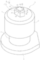
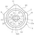
- the stud pin 1 is made of aluminum, an aluminum alloy or the like by molding or the like.
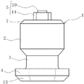
- the body 2, the shank 3 that continues to the lower side of the body 2, the pedestal portion 4 that continues to the lower side, and the body 2 It is comprised with the shaft 5 provided in the upper surface center part.
- the body 2 is formed in a cylindrical shape.
- the “cylindrical shape” is not limited to a perfect circle in a plan view, but includes a slightly deformed ellipse and the like, and a polygonal shape connected by a plurality of line segments in a plan view. In the case of a polygonal shape, it is necessary to make the length of the line segment sufficiently short so that it is close to a circle so as to be in close contact with the inner surface of the pin hole 26 almost uniformly.
- cylindrical shape means a general figure including a figure surrounded by a curved line such as a perfect circle and an ellipse in a plan view, and a figure including a polygon surrounded by a short line segment. Any shape can be used as long as the adhesiveness with the inner surface constituting the surface is enhanced over the entire surface.
- the outer edge of the upper surface of the body 2 is constituted by a tapered surface 7.
- the tapered surface 7 is the first region that comes into contact with the road surface when the stud pin 1 is mounted on a pneumatic tire (stud tire) and travels on the road surface.
- a pneumatic tire stud tire
- a straight line extending in the longitudinal direction through the center is an axis (centroid).
- the position of this axis is the same for the following pedestal 4 and shaft 5 as well.
- a straight line extending in the left-right direction orthogonal to the axis is a horizontal axis
- a straight line extending in the vertical direction orthogonal to the horizontal axis is a vertical axis.
- the pedestal portion 4 is formed in a vertically long shape in which the maximum length a in the vertical axis direction and the maximum length b in the horizontal axis direction satisfy a> b in plan view.
- a projecting portion 11 projecting in a triangular shape is formed by two inclined portions 10 in a first region located on one end side in the longitudinal axis direction of the pedestal portion 4, that is, one side across the horizontal axis.
- the protrusion 11 is arranged in only one side of the vertical axis with the horizontal axis as the center in plan view, and is bilaterally symmetric with respect to the vertical axis.
- shaft is set to less than 90 degrees, and an especially preferable angle is 45 degrees.
- Linear portions 9 extending in parallel with each other from the lower end portion of each inclined portion 10 toward the horizontal axis extend. Thereby, the site
- a semicircular portion 12 surrounded by an arc portion 12a is formed in one end side of the pedestal portion 4 in the vertical axis direction, that is, in the second region located on the other side across the horizontal axis.
- the first region and the second region are formed so as to be asymmetrical about the horizontal axis.
- first region and the second region is not limited to the above shape, but it is preferably formed in a vertically long shape that satisfies a> b.
- a tapered surface 13 is formed on the lower surface of the outer edge portion of the pedestal portion 4.
- the shaft 5 includes a first protrusion 14 having an odd-numbered square shape (here, a pentagon) in plan view.
- the first edge portion 15 including one side (edge) of the first protrusion 14 is a plane parallel to the side surface 6 of the body 2.
- the first edge portion 15 is set to be shorter than the length of the body side edge portion 8a.
- the second edge portion 16 and the third edge portion 17 on both sides adjacent to the first edge portion 15 are opposed to the arc portion of the pedestal portion 4.
- the fourth edge portion 18 adjacent to the second edge portion 16 and the fifth edge portion 19 adjacent to the third edge portion 17 face each inclined portion 10 of the pedestal portion 4.
- a second protrusion 20 is formed on the upper surface of the first protrusion 14.
- the second protrusion 20 has a rectangular shape in plan view, and one of the long sides thereof is a sixth edge 21 that is parallel to the first edge 15 of the first protrusion 14.
- the other edge portions (the seventh edge portion 22, the eighth edge portion 23, and the ninth edge portion 24) of the second protrusion 20 are different in the extending direction from the other edge portions of the first protrusion 14. Yes.
- the shaft 5 is provided so that its axis coincides with the axis of the body 2. Thereby, a sufficient distance can be secured in all directions from the outer edge of the body 2 to the shaft 5.
- the number of edge portions of the second protrusion 20 is smaller than that of the first protrusion 14.
- the first protrusion 14 has five locations and the second protrusion 20 has four locations.
- the height of the shaft 5 is 0.5 mm or more and 2.5 mm or less here. This is because if it is less than 0.5 mm, the function as the shaft 5 cannot be sufficiently exhibited, and if it exceeds 2.5 mm, the shaft 5 is grounded before the body 2 and is easily damaged.
- the ratio of the height of the second protrusion 20 to the first protrusion 14 is set to 10% or more and 80% or less. If it is less than 10%, the edge effect of the second protrusion 20 is insufficient, and if it exceeds 80%, the edge effect of the first protrusion 14 cannot be sufficiently exhibited.
- the shaft 5 can also be composed of three or more stages.
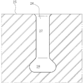
- the stud pin 1 having the above-described configuration is used by being mounted in a pin hole 26 formed in the tread portion 25 of the stud tire as shown in FIG.
- the pin hole 26 is composed of a small diameter portion 27 having the same inner diameter and an enlarged diameter portion 28 at the tip thereof.
- the mounting operation of the stud pin 1 in the pin hole 26 is automatically performed by a pin driving device (not shown).
- a pin driving device not shown.
- the shape of the pedestal portion 4 is not a point-symmetrical shape such as a circle, but a vertically long irregular shape as described above, it is possible to easily grasp the direction and accurately attach it to the pin hole 26. it can.
- the first side surface of the shaft 5 is positioned on the tire kicking side so as to extend in the tire width direction perpendicular to the tire circumferential direction. In this state, a portion above the upper end portion (tapered surface 7) of the body 2 of the stud pin 1 is exposed from the surface of the tread portion 25.
- the upper edge portion of the body 2 first collides with the road surface.
- a tapered surface 7 is formed on the outer edge portion of the upper end of the body 2. For this reason, even if the upper end outer edge portion of the body 2 collides with the road surface, the impact force per unit area on the road surface can be suppressed. As a result, even when traveling on a dry road surface, it is possible to avoid problems such as road surface cracks. Further, since the body 2 itself is formed in a columnar shape, it has sufficient strength against a collision with the road surface, and is not easily damaged (durable) even when used for a long period of time.
- the shaft 5 that collides with the road surface is composed of two stages, and the directions of the peripheral sharp edges are different between the first protrusion 14 and the second protrusion 20 except for one point. Therefore, the edge effect can be sufficiently exhibited. That is, if it goes straight, the 1st edge part 15 will act on a road surface (ice surface). Further, when cornering traveling on a curve, the second edge portion 16 or the third edge portion 17 prevents a lateral deviation with respect to the road surface. Further, when the brake is stepped on, the fourth edge portion 18 and the fifth edge portion 19 apply a braking force to the road surface.
- the stud pin 1 includes a shank 3 having a diameter smaller than that of the body 2 and a pedestal portion 4 having a diameter larger than that of the body 2 subsequent thereto.
- the body 2 is formed in a columnar shape and is in close contact with the inner surface constituting the pin hole 26, so that the prevention effect is enhanced.
- the base part 4 is formed so that it may spread outside from the perimeter of the body 2 by planar view, the prevention effect is heightened also in this point.
- the pedestal portion 4 since the pedestal portion 4 has a longer vertical axis length than the horizontal axis length, it can effectively exert a retaining effect against the force acting from the road surface at the start of running and braking. . Further, the boundary portion between the straight portion 9 and the inclined portion 10 of the pedestal portion and the vicinity thereof enhance the removal effect during cornering.
- Tests were conducted on the retaining property and the edge performance using the comparative example in which the plan view of the body 2 and the pedestal part 4 is circular and the stud pins of the examples shown in FIGS. 1 to 3.
- tire size 195 / 65R15
- air pressure Fr / Re 220/220 (kPa) was used.
- a wire was connected to the stud pin 1 mounted in the pin hole 26 and pulled at a constant speed in the front-rear direction, the oblique direction, and the lateral direction. The tensile force was gradually increased, and the evaluation was performed based on the tensile force when the stud pin 1 was pulled out from the pin hole 26.
- edge performance test test tires were mounted on a test vehicle (1500 cc, 4WD middle sedan vehicle), traveled on an ice road surface, and edge performance (driving performance, braking performance, and cornering performance) was evaluated.
- edge performance driving performance, braking performance, and cornering performance
- Examples 1 to 9 were index-evaluated with the case of Comparative Example 1 being 100.
- the driving performance was evaluated by the elapsed time from the stop state until the travel distance reached 30 m on the ice road surface.
- the braking performance was evaluated by the braking distance when the braking force was applied by ABS (Antilock Brake System) at a speed of 40 km / h.
- ABS Antilock Brake System
- the turning performance was similarly evaluated by the turning radius when turning at a speed of 40 km / h.
- the pedestal portion 4 having a vertically long asymmetric shape was able to improve the retaining property in all directions.
- the effect which was excellent in all the items of the edge effect was exhibited by each edge part.
- the reason for this edge effect is that the direction of the edge portion can be freely set and that the edge portion can be lengthened by using two stages.
- the first edge portion 15 of the first protrusion 14 of the shaft 5 is arranged on the tire kicking side so as to extend in the tire width direction perpendicular to the tire circumferential direction. You may make it arrange
- the shaft 5 has an odd-numbered square shape in plan view, but may be configured by one straight line portion and other arc portions.
- the arc portion may be formed in a substantially arc shape connected by a plurality of line segments having a shorter length than the straight line portion.
- the straight portions 9 that are parallel to each other in plan view are formed on the pedestal portion 4.
- the inclined portion 10 may be formed so that only the arc portion 12 a is continuous.
- the linear part 9 may be comprised by another circular arc part in which a curvature radius differs from the circular arc part 12a. Also by this, a corner
- the second region of the pedestal portion 4 is configured only by the arc portion 12a.
- a linear portion 12b parallel to the horizontal axis is formed in the second region. It may be.
- the shaft 5 is different from that shown in FIG. 3 in that the shaft 5 is rotated 180 degrees around the axis. According to this configuration, it is possible to effectively prevent the positional deviation with respect to the force that the linear portion 12b acts in the rotation direction.
Landscapes
- Engineering & Computer Science (AREA)
- Mechanical Engineering (AREA)
- Tires In General (AREA)
Priority Applications (3)
| Application Number | Priority Date | Filing Date | Title |
|---|---|---|---|
| RU2019111426A RU2722736C1 (ru) | 2016-10-26 | 2017-06-08 | Шиповой штифт и пневматическая шина, оснащенная шиповым штифтом |
| CA3040244A CA3040244C (en) | 2016-10-26 | 2017-06-08 | Stud pin and pneumatic tire provided with stud pin |
| EP17865059.4A EP3533631A4 (en) | 2016-10-26 | 2017-06-08 | NAIL HEAD AND TIRE PROVIDED WITH NAIL HEADS |
Applications Claiming Priority (2)
| Application Number | Priority Date | Filing Date | Title |
|---|---|---|---|
| JP2016209196A JP6663836B2 (ja) | 2016-10-26 | 2016-10-26 | スタッドピン及びスタッドピンを備えた空気入りタイヤ |
| JP2016-209196 | 2016-10-26 |
Publications (1)
| Publication Number | Publication Date |
|---|---|
| WO2018078937A1 true WO2018078937A1 (ja) | 2018-05-03 |
Family
ID=62024686
Family Applications (1)
| Application Number | Title | Priority Date | Filing Date |
|---|---|---|---|
| PCT/JP2017/021233 Ceased WO2018078937A1 (ja) | 2016-10-26 | 2017-06-08 | スタッドピン及びスタッドピンを備えた空気入りタイヤ |
Country Status (5)
| Country | Link |
|---|---|
| EP (1) | EP3533631A4 (enExample) |
| JP (1) | JP6663836B2 (enExample) |
| CA (1) | CA3040244C (enExample) |
| RU (1) | RU2722736C1 (enExample) |
| WO (1) | WO2018078937A1 (enExample) |
Cited By (4)
| Publication number | Priority date | Publication date | Assignee | Title |
|---|---|---|---|---|
| EP3670210A1 (en) * | 2018-12-18 | 2020-06-24 | The Goodyear Tire & Rubber Company | Winter tire stud |
| EP3674105A1 (en) * | 2018-12-28 | 2020-07-01 | Sumitomo Rubber Industries, Ltd. | Advanced ice grip device and pneumatic tire with advanced ice grip device |
| CN116157282A (zh) * | 2020-08-06 | 2023-05-23 | 横滨橡胶株式会社 | 防滑钉及具备该防滑钉的轮胎 |
| RU2800059C2 (ru) * | 2018-12-28 | 2023-07-17 | Сумитомо Раббер Индастриз, Лтд. | Усовершенствованное устройство для сцепления со льдом и пневматическая шина с усовершенствованным устройством для сцепления со льдом |
Citations (5)
| Publication number | Priority date | Publication date | Assignee | Title |
|---|---|---|---|---|
| US20130000807A1 (en) * | 2011-06-28 | 2013-01-03 | Frederic Michel-Jean Pons | Anti-skid stud for insertion into the tread of a vehicle tire and pneumatic tire comprising such anti-skid studs |
| JP2013023111A (ja) * | 2011-07-22 | 2013-02-04 | Bridgestone Corp | タイヤ用スパイクおよびスパイクタイヤ |
| JP2014180952A (ja) * | 2013-03-19 | 2014-09-29 | Bridgestone Corp | スタッドピンおよびこれを用いたタイヤ |
| JP2016078482A (ja) * | 2014-10-09 | 2016-05-16 | 東洋ゴム工業株式会社 | スタッドピン及びスタッドタイヤ |
| JP2016097836A (ja) * | 2014-11-21 | 2016-05-30 | 株式会社ブリヂストン | スタッド、及び、スタッダブルタイヤ |
Family Cites Families (5)
| Publication number | Priority date | Publication date | Assignee | Title |
|---|---|---|---|---|
| RU2152318C1 (ru) * | 1998-02-16 | 2000-07-10 | ОАО "Нижнекамскшина" | Устройство для шипования шин |
| RU2148498C1 (ru) * | 1998-03-30 | 2000-05-10 | ОАО"Нижнекамскшина" | Шип противоскольжения для шин транспортных средств |
| WO1999056976A1 (en) * | 1998-04-30 | 1999-11-11 | Otkrytoe Aktsionernoe Obschestvo 'nizhnekamskshina' | Antiskid spike for vehicle tyres |
| USD551614S1 (en) * | 2005-05-13 | 2007-09-25 | Nokian Tyres Plc | Tire stud |
| DE102011000563A1 (de) * | 2011-02-08 | 2012-08-09 | Continental Reifen Deutschland Gmbh | Spike und Fahrzeugluftreifen mit Spikes |
-
2016
- 2016-10-26 JP JP2016209196A patent/JP6663836B2/ja active Active
-
2017
- 2017-06-08 RU RU2019111426A patent/RU2722736C1/ru active
- 2017-06-08 CA CA3040244A patent/CA3040244C/en not_active Expired - Fee Related
- 2017-06-08 EP EP17865059.4A patent/EP3533631A4/en not_active Withdrawn
- 2017-06-08 WO PCT/JP2017/021233 patent/WO2018078937A1/ja not_active Ceased
Patent Citations (5)
| Publication number | Priority date | Publication date | Assignee | Title |
|---|---|---|---|---|
| US20130000807A1 (en) * | 2011-06-28 | 2013-01-03 | Frederic Michel-Jean Pons | Anti-skid stud for insertion into the tread of a vehicle tire and pneumatic tire comprising such anti-skid studs |
| JP2013023111A (ja) * | 2011-07-22 | 2013-02-04 | Bridgestone Corp | タイヤ用スパイクおよびスパイクタイヤ |
| JP2014180952A (ja) * | 2013-03-19 | 2014-09-29 | Bridgestone Corp | スタッドピンおよびこれを用いたタイヤ |
| JP2016078482A (ja) * | 2014-10-09 | 2016-05-16 | 東洋ゴム工業株式会社 | スタッドピン及びスタッドタイヤ |
| JP2016097836A (ja) * | 2014-11-21 | 2016-05-30 | 株式会社ブリヂストン | スタッド、及び、スタッダブルタイヤ |
Non-Patent Citations (1)
| Title |
|---|
| See also references of EP3533631A4 * |
Cited By (5)
| Publication number | Priority date | Publication date | Assignee | Title |
|---|---|---|---|---|
| EP3670210A1 (en) * | 2018-12-18 | 2020-06-24 | The Goodyear Tire & Rubber Company | Winter tire stud |
| US11084331B2 (en) | 2018-12-18 | 2021-08-10 | The Goodyear Tire & Rubber Company | Winter tire stud |
| EP3674105A1 (en) * | 2018-12-28 | 2020-07-01 | Sumitomo Rubber Industries, Ltd. | Advanced ice grip device and pneumatic tire with advanced ice grip device |
| RU2800059C2 (ru) * | 2018-12-28 | 2023-07-17 | Сумитомо Раббер Индастриз, Лтд. | Усовершенствованное устройство для сцепления со льдом и пневматическая шина с усовершенствованным устройством для сцепления со льдом |
| CN116157282A (zh) * | 2020-08-06 | 2023-05-23 | 横滨橡胶株式会社 | 防滑钉及具备该防滑钉的轮胎 |
Also Published As
| Publication number | Publication date |
|---|---|
| CA3040244C (en) | 2021-05-04 |
| EP3533631A1 (en) | 2019-09-04 |
| EP3533631A4 (en) | 2020-06-03 |
| RU2722736C1 (ru) | 2020-06-03 |
| JP6663836B2 (ja) | 2020-03-13 |
| CA3040244A1 (en) | 2018-05-03 |
| JP2018069819A (ja) | 2018-05-10 |
Similar Documents
| Publication | Publication Date | Title |
|---|---|---|
| WO2018078937A1 (ja) | スタッドピン及びスタッドピンを備えた空気入りタイヤ | |
| JP6730161B2 (ja) | スタッドピン及びスタッドピンを備えた空気入りタイヤ | |
| JP6691465B2 (ja) | スタッドピン及びスタッドピンを備えた空気入りタイヤ | |
| JP6691860B2 (ja) | スタッドピン及びスタッドピンを備えた空気入りタイヤ | |
| JP6826413B2 (ja) | スタッドピン及びスタッドピンを備えた空気入りタイヤ | |
| WO2018078938A1 (ja) | スタッドピン及びスタッドピンを備えた空気入りタイヤ | |
| WO2018078932A1 (ja) | スタッドピン及びスタッドピンを備えた空気入りタイヤ | |
| JP5937700B2 (ja) | スタッドピン及びそれを備える空気入りタイヤ | |
| JP6688202B2 (ja) | スタッドピンを備えたスタッドタイヤ | |
| JP2018069815A (ja) | スタッドピン及びスタッドピンを備えた空気入りタイヤ | |
| WO2018078933A1 (ja) | スタッドピン及びスタッドピンを備えた空気入りタイヤ | |
| JP2018069820A (ja) | スタッドピン及びスタッドピンを備えた空気入りタイヤ | |
| WO2018078935A1 (ja) | スタッドピン及びスタッドピンを備えた空気入りタイヤ | |
| CA3040239C (en) | Stud pin and pneumatic tire provided with stud pin |
Legal Events
| Date | Code | Title | Description |
|---|---|---|---|
| 121 | Ep: the epo has been informed by wipo that ep was designated in this application |
Ref document number: 17865059 Country of ref document: EP Kind code of ref document: A1 |
|
| ENP | Entry into the national phase |
Ref document number: 3040244 Country of ref document: CA |
|
| NENP | Non-entry into the national phase |
Ref country code: DE |
|
| ENP | Entry into the national phase |
Ref document number: 2017865059 Country of ref document: EP Effective date: 20190527 |