WO2018076834A1 - 一种多式联运互通系统 - Google Patents
一种多式联运互通系统 Download PDFInfo
- Publication number
- WO2018076834A1 WO2018076834A1 PCT/CN2017/094307 CN2017094307W WO2018076834A1 WO 2018076834 A1 WO2018076834 A1 WO 2018076834A1 CN 2017094307 W CN2017094307 W CN 2017094307W WO 2018076834 A1 WO2018076834 A1 WO 2018076834A1
- Authority
- WO
- WIPO (PCT)
- Prior art keywords
- cargo
- loading device
- cargo loading
- vehicle
- sports
- Prior art date
Links
Images


Classifications
-
- G—PHYSICS
- G06—COMPUTING; CALCULATING OR COUNTING
- G06Q—INFORMATION AND COMMUNICATION TECHNOLOGY [ICT] SPECIALLY ADAPTED FOR ADMINISTRATIVE, COMMERCIAL, FINANCIAL, MANAGERIAL OR SUPERVISORY PURPOSES; SYSTEMS OR METHODS SPECIALLY ADAPTED FOR ADMINISTRATIVE, COMMERCIAL, FINANCIAL, MANAGERIAL OR SUPERVISORY PURPOSES, NOT OTHERWISE PROVIDED FOR
- G06Q10/00—Administration; Management
- G06Q10/08—Logistics, e.g. warehousing, loading or distribution; Inventory or stock management
- G06Q10/083—Shipping
- G06Q10/0835—Relationships between shipper or supplier and carriers
- G06Q10/08355—Routing methods
-
- B—PERFORMING OPERATIONS; TRANSPORTING
- B61—RAILWAYS
- B61B—RAILWAY SYSTEMS; EQUIPMENT THEREFOR NOT OTHERWISE PROVIDED FOR
- B61B13/00—Other railway systems
- B61B13/04—Monorail systems
- B61B13/06—Saddle or like balanced type
-
- B—PERFORMING OPERATIONS; TRANSPORTING
- B61—RAILWAYS
- B61B—RAILWAY SYSTEMS; EQUIPMENT THEREFOR NOT OTHERWISE PROVIDED FOR
- B61B3/00—Elevated railway systems with suspended vehicles
-
- B—PERFORMING OPERATIONS; TRANSPORTING
- B61—RAILWAYS
- B61D—BODY DETAILS OR KINDS OF RAILWAY VEHICLES
- B61D47/00—Loading or unloading devices combined with vehicles, e.g. loading platforms, doors convertible into loading and unloading ramps
-
- B—PERFORMING OPERATIONS; TRANSPORTING
- B65—CONVEYING; PACKING; STORING; HANDLING THIN OR FILAMENTARY MATERIAL
- B65G—TRANSPORT OR STORAGE DEVICES, e.g. CONVEYORS FOR LOADING OR TIPPING, SHOP CONVEYOR SYSTEMS OR PNEUMATIC TUBE CONVEYORS
- B65G63/00—Transferring or trans-shipping at storage areas, railway yards or harbours or in opening mining cuts; Marshalling yard installations
- B65G63/04—Transferring or trans-shipping at storage areas, railway yards or harbours or in opening mining cuts; Marshalling yard installations with essentially-horizontal transit by bridges equipped with conveyors
-
- B—PERFORMING OPERATIONS; TRANSPORTING
- B65—CONVEYING; PACKING; STORING; HANDLING THIN OR FILAMENTARY MATERIAL
- B65G—TRANSPORT OR STORAGE DEVICES, e.g. CONVEYORS FOR LOADING OR TIPPING, SHOP CONVEYOR SYSTEMS OR PNEUMATIC TUBE CONVEYORS
- B65G67/00—Loading or unloading vehicles
- B65G67/02—Loading or unloading land vehicles
Definitions
- the invention relates to the technical field of logistics, in particular to a multimodal intermodal communication system.
- Multi-modal operation is a high-efficiency transportation mode and represents the development direction of the logistics industry.
- 2014-2020 National Medium- and Long-Term Plan for Logistics Industry Development
- 18 mentioned the development of multimodal transport and the multimodal transport to the strategic level of logistics development.
- the “13th Five-Year” development plan of the Ministry of Transport clearly puts forward the development goal of “seamless connection” of freight transportation, pointing out that it is vigorously developing multi-modal transport technology and equipment, focusing on building efficient facilities, fast hub transportation, information sharing and equipment.
- the multi-modal transport organization system which integrates standard professional and service integration, focuses on the development of multi-modal transport system with cargo loading devices and semi-trailers as standard carrying units.
- the multi-modal operation of cargo loading devices is an advanced mode of transportation and has become an important symbol of the internationalization of international freight transportation.
- China's various modes of transportation for roads, railways, waterways and civil aviation have a large scale, but various modes of transportation are scattered and lack of organic connection.
- the road cargo loading device transport truck (hereinafter referred to as the highway truck) is the only connecting tool for realizing short-distance transportation of cargo loading devices between ports and railways and aviation logistics centers.
- the transportation mode is single, the transportation efficiency is low, and the ground transportation is Transportation has caused great pressure and environmental pollution, which has led to the slow development of the country's integrated multimodal transport and affects the development of the national integrated transportation system.
- the invention realizes the technical effect of multimodal transport between the port, the railway and the aviation logistics center by providing a multimodal intermodal communication system.
- the invention provides a multimodal interworking system, the system comprising at least:
- a sports car that is movably disposed on a track beam of the track system
- An adapter device for transferring the cargo loading device from the transportation vehicle to the cargo sports vehicle and loading the cargo sports vehicle, or unloading and transporting the cargo loading device from the cargo sports vehicle to the transportation vehicle;
- a processor coupled to the cargo vehicle and the transfer device to control the transfer device to transfer the cargo loading device, and to control the cargo sports car after the cargo loading device is snapped onto the cargo sports vehicle Moving on the track beam;
- the cargo loading device when the cargo loading device needs to be operated, the cargo loading device is transferred from the transportation vehicle to the cargo sports vehicle and loaded onto the cargo sports vehicle through the switching device, and the processor controls the cargo transportation
- the motor vehicle moves over the track beam or the transfer device unloads and transports the cargo loading device from the cargo vehicle to the vehicle.
- the left and right portions of the rail system are symmetrically mounted with two rail beams, and the two rail beams are respectively provided with a plurality of rows of moving sports cars movable thereon, and a plurality of rows of the sports cars on each side.
- the lower end is located below the rail beam and carries the cargo loading device.
- the rail beam is a box structure, and a lower surface of the rail beam is provided with an opening extending through the front and rear ends thereof, and the cargo moving vehicle is supported on a lower surface of the inner surface of the rail beam.
- each of the cargo sports cars includes a cargo sports car bogie supported on a lower surface of the inner surface of the rail beam, the cargo sports car bogie including a bogie frame, and the front and rear ends of the bogie frame are respectively connected with a gear box
- the left and right sides of each of the gear boxes are symmetrically disposed with two output shafts, and each of the output shafts is respectively mounted with a running wheel, and the cargo sports car bogie travels on the track beam through four running wheels
- two The front and the rear ends of the gear box are respectively connected with the two frames to form a connection, and the front and rear ends of the two intermediate frames are connected with two traction motors for controlling the movement of the sports car
- a lower end of the bogie is coupled to the cargo loading device integrated spreader through the opening through a suspension, the lower end of the cargo loading device integrated spreader being coupled to the cargo loading device; the processor being coupled to the traction motor.
- each of the traction motors are symmetrically connected with two guide wheel mounting seats, and the two guide wheel mounting seats are respectively mounted with guiding wheels, and the opening of the rail beam is left and right.
- the walls are each provided with a guide rail, and the two guide wheels are respectively moved along the two guide rails.
- the suspension device includes a center pin, an upper end of the center pin is connected to a lower end of the bogie frame, a lower end of the center pin is connected with a connecting seat, and the connecting seat passes through a plurality of first pin shafts and two Suspension arm connections, the lower ends of the two suspension arms being coupled to the mount by a plurality of second pins that are coupled to the cargo loading device integrated spreader.
- the switching device includes at least: a conveying mechanism, a gripping mechanism, and a lifting mechanism; the gripping mechanism places a cargo loading device on the conveying mechanism; the conveying mechanism transports the cargo loading device to The lifting mechanism; the lifting mechanism lifts or lowers the cargo loading device; loading the cargo loading device onto the cargo moving vehicle or removing the cargo loading device from the cargo moving vehicle; The conveying mechanism, the gripping mechanism, and the lifting mechanism are communicatively connected.
- the transport mechanism includes at least: a first frame, a chain, a first rotating shaft set, and a power An output device; the first rotating shaft group is disposed on the first frame; each of the rotating shafts of the first rotating shaft group has a gear; the chain is sleeved on the gear to drive the first rotating shaft group Each of the rotating shafts rotates; the power output end of the power output device is coupled to the chain.
- the grasping mechanism at least includes: a telescopic arm, a first support rod, a second support rod, a first telescopic rod, a second telescopic rod, a third telescopic rod and a spreader; One end is fixedly connected to the first frame, the second end of the first support rod is hinged with the first end of the second support rod; the second end of the second support rod is hinged with the telescopic arm a first end of the first telescopic rod is fixedly connected to the first frame, a second end of the first telescopic rod is hinged with the second support rod; and a first end of the second telescopic rod is The first end of the second support rod is hinged, the second end of the second telescopic rod is hinged with the first end of the telescopic arm; the first end of the third telescopic rod is opposite to the first end of the telescopic arm The second end of the third telescopic rod is fixedly connected to the second end of the telescopic rod
- the switching device includes a chassis, a lifting device, a lifting platform, a lifting drive device, a plurality of traveling wheels, and a traveling driving device;
- the lifting device is connected between the chassis and the lifting platform;
- the lifting drive device is connected to the lifting device, and the lifting device is driven to drive the lifting platform to rise or fall;
- the plurality of traveling wheels are fixed under the chassis;
- the travel drive device is fixed on the chassis, and is connected to the traveling wheel to drive the traveling wheel to rotate;
- the processor is communicatively coupled to the elevation drive device and the travel drive device.
- the ports and railways, the aviation logistics center are connected, the cargo loading device is transferred by the processor control transfer device, and the cargo moving vehicle is moved on the rail beam after the cargo loading device is attached to the cargo sports car, thereby realizing Multimodal transport between ports and railways, and aviation logistics centers.
- the replacement of road cargo loading devices to transport trucks through rail systems not only improves transportation efficiency, but also reduces the pressure on ground transportation and protects the environment.
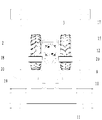
- FIG. 1 is a schematic structural diagram of a multi-modal interworking system according to an embodiment of the present invention
- Embodiment 1 of a track system in a multi-modal interworking system according to an embodiment of the present invention
- Figure 3 is a schematic structural view of the bogie and track beam of the goods sports car of Figure 2;
- Figure 4 is a top plan view of the bogie of the cargo sports car of Figure 2;
- Figure 5 is a right side view showing the structure of the truck of Figure 2;
- FIG. 6 is a schematic front view showing a structure of a suspension device according to Embodiment 2 of a track system in a multi-modal interworking system according to an embodiment of the present invention
- FIG. 7 is a schematic top right structural view of a suspension device according to Embodiment 2 of a track system in a multi-modal interworking system according to an embodiment of the present invention.
- FIG. 8 is a schematic diagram showing a third main structure of a track system in a multi-modal interworking system according to an embodiment of the present invention.
- FIG. 9 is a schematic top right structural diagram of a third embodiment of a track system in a multi-modal interworking system according to an embodiment of the present invention.
- FIG. 10 is a structural diagram of a first type of switching device in a multi-modal interworking system according to an embodiment of the present invention. schematic diagram;
- FIG. 11 is a schematic structural diagram of a second type of switching device in a multi-modal interworking system according to an embodiment of the present invention.
- FIG. 12 is a schematic structural diagram of a third type of switching device in a multi-modal interworking system according to an embodiment of the present invention.
- FIG. 13 is a front view of a third type of switching device in a multi-modal interworking system according to an embodiment of the present invention.
- the embodiment of the invention realizes the technical effect of multimodal transport between the port, the railway and the aviation logistics center by providing a multimodal intermodal communication system.
- the technical solution in the embodiment of the present invention is to solve the above technical problem, and the general idea is as follows:
- the ports and railways, the aviation logistics center are connected, the cargo loading device is transferred by the processor control transfer device, and the cargo moving vehicle is moved on the rail beam after the cargo loading device is attached to the cargo sports car, thereby realizing Multimodal transport between ports and railways, and aviation logistics centers.
- the replacement of road cargo loading devices to transport trucks through rail systems not only improves transportation efficiency, but also reduces the pressure on ground transportation and protects the environment.
- a multi-modal interworking system provided by an embodiment of the present invention includes at least:
- a sport utility vehicle 31 movably disposed on a track beam of the track system 30;
- the processor is coupled to the utility vehicle 31 and the transfer device 32 to control the transfer device 32 to transfer the cargo loading device 33, and after the cargo loading device 33 is snapped onto the cargo sports vehicle 31, the cargo sports vehicle 31 is moved over the track beam. .
- the cargo loading device 33 when the cargo loading device 33 needs to be operated, the cargo loading device 33 is transferred from the transportation tool to the cargo sports vehicle 31 through the switching device 32 and loaded with the loading sports vehicle 31, and the processor controls the cargo sports vehicle 31 to move on the rail beam, or The transfer device 32 detaches the cargo loading device 33 from the goods moving vehicle 31 and transports it to the vehicle.
- the structure of the first embodiment of the present invention includes a rail system 1 including a rail strut 30 and two rail beams 2, and the upper lower surface of the rail strut 30 is symmetrically opened to the left and right sides.
- the C-shaped track groove 8 passes through the front and rear ends of the track system 1.
- the two track beams 2 are installed in the two track grooves 8.
- the track system 1 can be conveniently and stably disposed in the isolation belt.
- the rail beam 2 is a thin-walled steel box rail beam structure, and the lower surface of the rail beam 2 is provided with an opening 9 extending through the front and rear ends thereof, and the inner cavities of the two rail beams 2 are respectively provided with a plurality of columns at the rail beam 2
- the inner moving sports car 31, in this embodiment, is provided with two rows of cargo sports cars 31 supported on the lower surface of the inner surface of the rail beam 2, respectively.
- the lower end of the cargo vehicle 31 is coupled to a cargo loading device, which is a cargo loading device 33.
- the cargo sports car 31 includes a cargo sports car bogie 3, a suspension device 10 connected to the underside of the cargo sports car bogie 3, and a cargo loading device integrated spreader 11 connected to the underside of the suspension device 10, the cargo loading device.
- the lower end of the integrated spreader 11 is connected to the cargo loading device 33.
- This embodiment adopts a super capacitor power supply mode.
- the utility car bogie 3 includes a bogie frame 12, the bogie frame 12 adopts a welded structure, and the front and rear ends of the bogie frame 12
- Two gear boxes 13 are connected by welding, and two output shafts 14 are symmetrically disposed on the left and right sides of each of the gear boxes 13, and the running wheels 15 are respectively mounted on the respective output shafts 14.
- the truck 3 is driven by the four running wheels 15 on the lower surface of the inner wall of the rail beam 2.
- the front and rear ends of the two gear boxes 13 are respectively connected by bolts to the two intermediate frames of the frame, and the two frames are connected in the middle.
- the front and rear ends of the composition 16 are connected to the outer casings of the two traction motors 17 that drive the truck 3 to be transported by bolts.
- Two guide wheel mounting seats 18 are symmetrically welded to the left and right lower portions of the outer casing of each traction motor 17, and guide wheel 19 is respectively mounted on the two guide wheel mounting seats 18, and the left and right side walls of the inner wall of the track beam 2 are respectively provided.
- the four cargo sports car bogies 3 travel on the two rail beams 2, so that the two cargo loading devices 33 suspended below can be driven to move in the direction of the track beam 2, which is easily loaded by electric control.
- the transportation of the device 33, the four running wheels 15 of the various sports car bogies 3 ensure smooth running on the track beam 2, and the four guiding wheels 19 of each cargo sports car bogie 3 move forward and backward along the guiding rail 20 thereof.
- the arrangement of the guide wheels 19 can ensure the smooth steering of the cargo sports car bogie 3, while the running wheels 15 and the guide wheels 19 are all rubber tires, so that the cargo sports car bogie 3 can achieve the shock absorption buffer during operation.
- the effect is also to use rubber tires to make the vehicle have good acceleration, deceleration performance and strong climbing ability, reduce the noise of the vehicle and the vibration of the track beam 2, and have better adaptability to the complex terrain of the port;
- the rail system 1 can be disposed in the isolation belt, and the multi-row trucks 31 are respectively operated on the two rail beams 2, which fully utilize the air space without affecting the interior of the port.
- the track beam 2 can also be selected from a track beam of a C-shaped channel structure, all of which fall within the scope of protection of the present invention.
- the second embodiment of the present invention comprises a rail system 1 comprising a rail strut 30 and two rail beams 2, and the upper left surface of the rail strut 30 is symmetrically opened with two C-shaped rail slots 8 and two rails.
- the trough 8 penetrates the front and rear ends of the rail system 1, and the two rail beams 2 are installed in the two rail grooves 8, and the rail system 1 can be conveniently and stably disposed in the partition belt.
- the rail beam 2 is a thin-walled steel box rail beam structure, and the lower surface of the rail beam 2 is provided with an opening 9 extending through the front and rear ends thereof, and the inner cavities of the two rail beams 2 are respectively provided with a plurality of columns at the rail beam 2
- the inner moving sports car 31, in this embodiment, is provided with two rows of cargo sports cars 31 supported on the lower surface of the inner surface of the rail beam 2, respectively. 4 and 5, the cargo sports car 31 includes a cargo sports car bogie 3, a suspension device 10 connected to the underside of the cargo sports car bogie 3, and a cargo loading device integrated spreader 11 connected to the underside of the suspension device 10, the cargo loading device. The lower end of the integrated spreader 11 is connected to the cargo loading device 33.
- the truck body bogie 3 includes a bogie frame 12, and the bogie frame 12 adopts a welded structure.
- the front and rear ends of the bogie frame 12 are respectively connected to two gear boxes 13 by welding, and the left and right sides of each gear box 13
- Two output shafts 14 are symmetrically disposed, and each of the output shafts 14 is mounted with a running wheel 15 respectively.
- the truck 3 is driven by the four running wheels 15 on the lower surface of the inner wall of the rail beam 2.
- the front and rear ends of the two gear boxes 13 are respectively connected by bolts to the two intermediate frames of the frame, and the two frames are connected in the middle.
- Composition of the front, rear and control of the sports car bogie The outer casings of the two traction motors 17 that are driven 3 are bolted together.
- Two guide wheel mounting seats 18 are symmetrically welded to the left and right lower portions of the outer casing of each traction motor 17, and guide wheel 19 is respectively mounted on the two guide wheel mounting seats 18, and the left and right side walls of the inner wall of the track beam 2 are respectively provided.
- the suspension device 10 includes a center pin 21, and the suspension device 10 is connected to the lower end of the bogie frame 12 through a center pin 21, and the lower end of the center pin 21 is connected with a connecting seat 22, and the connecting seat 22 passes through two
- the first pin 23 is connected to the two suspension arms 24, the suspension arm 24 is a bent plate body, and the lower ends of the two suspension arms 24 are connected to the mounting seat 26 via two second pins 25, the mounting seat 26 and the cargo loading device
- the integrated spreader 11 is connected.
- the processor is in signal connection with the traction motor 17 to control the traction motor 17 to start or stop.
- the working process and functions of the embodiment are basically the same as those of the first embodiment, and are not described herein again.
- the transmission of the cargo moving car bogie 3 in the three directions of the X-axis, the Y-axis, and the Z-axis is realized, and the cargo loading device 33 and the cargo sports car bogie are satisfied.
- FIG. 7 and FIG. 8 are schematic diagrams showing a front view and a right view of a third embodiment of the present invention, including a track system 1.
- the track system 1 includes a track pillar 30 and two track beams 2, and an upper lower surface of the track pillar 30 is left.
- Two C-shaped track grooves 8 are symmetrically opened on the right side.
- Two track grooves 8 pass through the front and rear ends of the track system 1.
- Two track beams 2 are installed in the two track grooves 8.
- the track system 1 is convenient and It is placed in the isolation belt.
- the rail beam 2 is a thin-walled steel box rail beam structure, and the lower surface of the rail beam 2 is provided with an opening 9 extending through the front and rear ends thereof, and the inner cavities of the two rail beams 2 are respectively provided
- the cargo sports car 31, which can be moved within the track beam 2, is provided with two rows of cargo sports cars 31 supported on the lower surface of the inner surface of the track beam 2 in the inner cavity of each track beam 2 in this embodiment. 4 and 5, the cargo sports car 31 includes a cargo sports car bogie 3, a suspension device 10 connected to the underside of the cargo sports car bogie 3, and a cargo loading device integrated spreader 11 connected to the underside of the suspension device 10, the cargo loading device. The lower end of the integrated spreader 11 is connected to the cargo loading device 33.
- the truck body bogie 3 includes a bogie frame 12, and the bogie frame 12 adopts a welded structure.
- the front and rear ends of the bogie frame 12 are respectively connected to two gear boxes 13 by welding, and the left and right sides of each gear box 13
- Two output shafts 14 are symmetrically disposed, and each of the output shafts 14 is mounted with a running wheel 15 respectively.
- the truck 3 is driven by the four running wheels 15 on the lower surface of the inner wall of the rail beam 2.
- the front and rear ends of the two gear boxes 13 are respectively connected by bolts to the two intermediate frames of the frame, and the two frames are connected in the middle.
- the front and rear ends of the composition 16 are bolted together with the outer casings of the two traction motors 17 that drive the trucks.
- Two guide wheel mounting seats 18 are symmetrically welded to the left and right lower portions of the outer casing of each traction motor 17, and guide wheel 19 is respectively mounted on the two guide wheel mounting seats 18, and the left and right side walls of the inner wall of the track beam 2 are respectively provided.
- Each of the running wheels 15 and the guide wheels 19 is made of rubber tires.
- the lower end of the cargo vehicle bogie 3 is connected to the cargo loading device integration spreader 11 through the opening 9 through the suspension device 10, and the lower end of the cargo loading device integrated spreader 11 is coupled to the cargo loading device 33. As shown in FIG. 5 and FIG.
- the suspension device 10 includes a center pin 21, and the suspension device 10 is connected to the lower end of the bogie frame 12 through a center pin 21, and the lower end of the center pin 21 is connected with a connecting seat 22, and the connecting seat 22 passes through two.
- the first pin 23 is connected to the two suspension arms 24, the suspension arm 24 is a bent plate body, and the lower ends of the two suspension arms 24 are connected to the mounting seat 26 via two second pins 25, the mounting seat 26 and the cargo loading device
- the integrated spreader 11 is connected.
- the cargo loading device integrated spreader 11 includes a main body structure 27 made of a rail, and the mount 26 is welded to the upper surface of the main body structure 27.
- Main structure 27 The front and rear parts are respectively provided with energy absorbing anti-collision devices 29 to prevent the impact of the sudden movement on the truck 3 of the sports car, and ensure the safety of the cargo sports car bogie 3 and the running cargo loading device 33.
- the collision device 29 can also be mounted at the end of the truck's bogie 3, and the position is not limited herein, and is within the scope of the present invention.
- a safety cable is reserved between the cargo sports car bogie 3 and the cargo loading device 33 to ensure that the cargo loading device 33 is accidentally dropped in the event of failure of the suspension device 10, etc., to ensure safe operation of the cargo sports car bogie 3.
- a power supply system 28 that provides power to the truck's bogie 3, which is powered by a supercapacitor that is coupled between the rail system 1 and the main structure 27 of the cargo loading device integrated spreader 11.
- the embodiment of the invention provides three configurations of the switching device 32.
- the first type of adapter device 32 includes at least: a transport mechanism, a gripping mechanism, and a lifting mechanism; the gripping mechanism places the cargo loading device 33 on the transport mechanism; the transport mechanism transports the cargo loading device 33 to the lift mechanism The lifting mechanism lifts or lowers the cargo loading device 33; loads the cargo loading device 33 onto the loading utility vehicle 31 or removes the cargo loading device 33 from the cargo moving vehicle 31; the processor communicates with the conveying mechanism, the grasping mechanism, and the lifting mechanism connection.
- the transport mechanism includes at least: a first frame 71, a chain, a first rotating shaft set 72, and a power output device; the first rotating shaft set 72 is disposed on the first frame 71; and the first rotating shaft set 72
- Each of the rotating shafts has a gear; the chain is sleeved on the gear to drive the rotating shafts of the first rotating shaft group 72; the power output end of the power output device is connected with the chain to drive the chain to rotate.
- the power output device is a motor.
- the lifting mechanism includes at least: a telescopic mechanism 73 and a base; and the telescopic end of the telescopic mechanism 73 is connected to the base.
- the base includes at least: a second frame 74 and a second rotating shaft set 75;
- the telescopic end of the telescopic mechanism 73 is coupled to the second frame 74;
- the second set of rotating shafts 75 is disposed on the second frame 74.
- the pedestal further includes at least: an sensing element for sensing whether the cargo loading device 33 reaches a predetermined location; the sensing element is disposed on the pedestal. The signal output of the sensing element is coupled to the signal input of the processor.
- the sensing element comprises: a displacement sensor and/or an infrared sensor.
- the structure of the grasping mechanism includes at least: a telescopic arm 76, a first support rod 77, a second support rod 78, a first telescopic rod 79, a second telescopic rod 710, a third telescopic rod 711, and a suspension.
- the first end of the first support rod 77 is fixedly coupled to the first frame 71, the second end of the first support rod 77 is hinged to the first end of the second support rod 78, and the second end of the second support rod 78 is The first end of the first telescopic rod 79 is fixedly connected to the first frame 71, the second end of the first telescopic rod 79 is hinged with the second support rod 78; the first end of the second telescopic rod 710 is The first end of the second support rod 78 is hinged, and the second end of the second telescopic rod 710 is hinged with the first end of the telescopic arm 76; the first end of the third telescopic rod 711 is fixedly connected with the first end of the telescopic arm 76, The second end of the third telescopic rod 711 is fixedly coupled to the second end of the telescopic arm 76; the second end of the telescopic arm 76 is coupled to the spreader 712.
- the first telescopic rod 79, the second telescopic rod 710, and the third telescopic rod 711 may be a pneumatic rod or a hydraulic rod.
- the embodiment of the present invention does not make a specific driving method for the telescopic rod. limit.
- a second type of adapter device 800 includes at least: a gripping mechanism and a lifting mechanism; the gripping mechanism places the cargo loading device on the lifting mechanism; and the lifting mechanism lifts or lowers the cargo loading device.
- the processor is communicatively coupled to the transport mechanism, the grasping mechanism, and the lifting mechanism.
- the structure of the lifting mechanism is described, and the lifting mechanism includes at least: a telescopic mechanism 83 and a base; The telescopic end of the telescopic mechanism 83 is connected to the base.
- the structure of the base is described.
- the base includes at least a frame 84 and a support base 85.
- the telescopic end of the telescopic mechanism 83 is coupled to the frame 84.
- the support base 85 is disposed on the frame 84.
- the structure of the pedestal is further described.
- the pedestal further includes at least: an sensing element for sensing whether the cargo loading device reaches a predetermined location; the sensing component is disposed on the pedestal.
- the signal output of the sensing element is coupled to the signal input of the processor.
- the sensing element includes: a displacement sensor and/or an infrared sensor or the like.
- the elevating mechanism further includes at least: a distance measuring element for sensing the amount of expansion and contraction of the telescopic mechanism 83; and the distance measuring element is disposed on the telescopic mechanism 83 and/or the base.
- the structure of the grasping mechanism includes at least: a telescopic arm 86, a first support rod 87, a second support rod 88, a first telescopic rod 89, a second telescopic rod 810, a third telescopic rod 811, and a suspension.
- the first end of the first support rod 87 is fixedly coupled to the first frame 81, the second end of the first support rod 87 is hinged to the first end of the second support rod 88, and the second end of the second support rod 88 is The first end of the first telescopic rod 89 is fixedly connected to the first frame 81, the second end of the first telescopic rod 89 is hinged with the second support rod 88; the first end of the second telescopic rod 810 is The first end of the second support rod 88 is hinged, and the second end of the second telescopic rod 810 is hinged with the first end of the telescopic arm 86; the first end of the third telescopic rod 811 is fixedly connected with the first end of the telescopic arm 86, The second end of the third telescopic rod 811 is fixedly connected to the second end of the telescopic arm 86; the second end of the telescopic arm 86 is connected to the spreader 812.
- the first telescopic rod 89, the second telescopic rod 810, and the third telescopic rod 811 may be a pneumatic rod or a hydraulic rod.
- the embodiment of the present invention does not specifically limit the driving manner of the telescopic rod. .
- the controller In order to implement the automation function of the embodiment of the present invention, at least: the controller; the controller letter The input end is communicatively connected with the signal output end of the sensing element and the distance measuring component, and the signal output end of the controller and the telescopic mechanism 83, the first telescopic rod 89, the second telescopic rod 810, the third telescopic rod 811, and the spreader 812 Signal input communication connection.
- the controller controls the telescopic mechanism 83, the first telescopic rod 89, the second telescopic rod 810, the third telescopic rod 811, and the spreader 812 to operate as needed.
- the third type of adapter includes a chassis 99, a lifting device 92, a lifting platform 910, a lifting drive 914, a plurality of traveling wheels 93 and a travel drive 94, and a translation device 917.
- the lifting device 92 is connected between the chassis 99 and the lifting platform 910;
- the lifting drive device 914 is connected to the lifting device 92, and the driving lifting device 92 drives the lifting platform 910 to rise or fall;
- a plurality of walking wheels 93 are fixed under the chassis 99;
- the travel drive device 94 is fixed to the chassis 99 and connected to the traveling wheel 93 to drive the traveling wheel 93 to rotate;
- the processor is communicatively coupled to the lift drive 914 and the travel drive 94.
- the surface of the lifting platform 910 opposite to the lifting device 92 is provided with a first locking group 911, a second locking group 912, and a second locking group that are locked at the bottom of the cargo loading device 33.
- the 912 is located outside the first lock group 911, and the second lock set 912 has a higher height than the first lock set 911.
- Two convex beams 913 are disposed on both ends of the lifting platform 910 opposite to the lifting device 92, and the second locking group 912 is disposed on the two convex beams 913.
- the first lock group 911 and the second lock group 912 are respectively four bumps.
- the chassis 99 includes at least two end beams 98, at least two side beams 97, a plurality of beams and a bottom plate 916. At least two ends of the two end beams 98 are respectively connected to at least two ends of the two measuring beams 97. A plurality of beams are disposed between the at least two end beams 98, and the two ends are respectively connected to at least the side beams 97.
- the bottom plate 916 is fixed to the at least two end beams 98, at least the side beams 97, and the plurality of beams. In other implementations In the mode, the bottom plate 916 may not be provided. Further, in the present embodiment, the running directions of the plurality of traveling wheels 93 are parallel to the longitudinal direction of the end beam 98.
- the walking wheel 93 can be a rubber wheel or a universal wheel.
- the kinetic energy supply mode of the transfer device can be powered by the super capacitor, and the speed electric pile is arranged at the starting position or the designated position.
- the cargo loading device connection process for transporting the cargo loading device 33 from the port cargo loading device terminal to the cargo loading device logistics center such as railway, highway or aviation by the embodiment of the present invention is as follows:
- the C0001# cargo loading device 33 is taken from the port cargo loading device terminal by the picking mechanism of the loading device 32 of the loading bay (assuming that the cargo loading device 33 is numbered C0001#), through the switching device 32
- the transport mechanism transports the C0001# cargo loading device 33 to the cargo loading device loading and unloading point where the cargo sports vehicle is docked, and then lifts the C0001# cargo loading device 33 to an appropriate height by the lifting mechanism of the switching device 32;
- the C0001# cargo loading device 33 is transferred from the cargo moving vehicle 31 by the lifting mechanism of the switching device 32 of the unloading station, and then the C0001# cargo loading device 33 is transferred to the conveying mechanism and the grasping mechanism of the switching device 32 to Pre-arranged on the road truck or railway cargo loading device transporter at the loading and unloading location. So far, the embodiment of the present invention ends the transportation process of the C0001# cargo loading device 33 from the port to the multimodal logistics center.
- the embodiment of the present invention can also transport the cargo loading device 33 from the cargo loading device logistics center such as railway, highway or aviation to the port cargo loading device terminal.
- the specific operation process is opposite to the above operation process, and will not be described herein.
- the port and rail, the air logistics center are connected by the track system 30, the cargo loading device 33 is transferred by the processor control switching device 32, and after the cargo loading device 33 is snapped onto the cargo sports car 31, the cargo sports car 31 is controlled in the track system. 30 moves, thus achieving multimodal transport between ports and railways, and aviation logistics centers.
- the replacement of road cargo loading devices to transport trucks through rail systems not only improves transportation efficiency, but also reduces the pressure on ground transportation and protects the environment.
- the embodiment of the invention realizes the interconnection between the distribution centers of various cargo loading devices by means of the air track system 30, and realizes the organic connection between the railway, water transportation, highway, aviation and other logistics systems, completely achieving the zero distance transfer.
- the seamless connection requirements can fully release the ground transportation capacity.
- the embodiment of the invention fully meets the national strategy of vigorously developing multimodal transport, and provides an overall solution for intelligent multi-modal transport and efficient transshipment of cargo loading devices.
Abstract
Description
Claims (10)
- 一种多式联运互通系统,其特征在于,所述系统至少包括:轨道系统;货运动车,可移动地设置在所述轨道系统的轨道梁上;转接装置,用于将货物装载器件从运输工具转送到货运动车下并装载上所述货运动车,或将货物装载器件从所述货运动车上卸下并运送到所述运输工具上;处理器,与所述货运动车和所述转接装置连接,以控制所述转接装置转运所述货物装载器件,并在货物装载器件卡接于所述货运动车上后,控制所述货运动车在所述轨道梁上移动;其中,在需要运转货物装载器件时,通过所述转接装置将所述货物装载器件从所述运输工具转送到所述货运动车下并装载上所述货运动车,所述处理器控制所述货运动车在所述轨道梁上移动,或者,所述转接装置将货物装载器件从所述货运动车上卸下并运送到所述运输工具上。
- 如权利要求1所述的系统,其特征在于,所述轨道系统的左、右部对称安装有两个轨道梁,两个所述轨道梁上分别设有多列可在其上移动的货运动车,各侧的多列所述货运动车下端位于轨道梁的下方吊挂有货物装载器件。
- 如权利要求2所述的系统,其特征在于,所述轨道梁为箱式结构,所述轨道梁的下表面设有贯通其前、后端的开口,所述货运动车支撑在轨道梁的内腔下表面。
- 如权利要求3所述的系统,其特征在于,每列所述货运动车包括支撑在轨道梁内腔下表面的货运动车转向架,所述货运动车转向架包括转向架构 架,所述转向架构架的前、后端分别连接有齿轮箱,各所述齿轮箱的左、右侧对称设置有两个输出轴,各所述输出轴上分别安装有走行轮,所述货运动车转向架通过四个走行轮在轨道梁上行驶,两个所述齿轮箱的前、后端分别与两个构架中间连接组成连接,两个所述构架中间连接组成的前、后端与控制货运动车转向架行驶的两个牵引电机连接,所述货运动车转向架的下端通过悬挂装置穿过所述开口与货物装载器件集成吊具连接,所述货物装载器件集成吊具的下端与货物装载器件连接;所述处理器与所述牵引电机连接。
- 如权利要求4所述的系统,其特征在于,各所述牵引电机的外壳左、右侧下部对称连接有两个导向轮安装座,两个所述导向轮安装座上分别安装有导向轮,所述轨道梁的开口左、右侧壁分别设有导向轨,两个所述导向轮分别沿两个导向轨移动。
- 如权利要求5所述的系统,其特征在于,所述悬挂装置包括中心销,所述中心销的上端与转向架构架的下端连接,所述中心销的下端连接有连接座,所述连接座通过多个第一销轴与两个悬挂臂连接,两个所述悬挂臂的下端通过多个第二销轴与安装座连接,所述安装座与货物装载器件集成吊具连接。
- 如权利要求1所述的系统,其特征在于,所述转接装置至少包括:传送机构、抓取机构及升降机构;所述抓取机构将货物装载器件放置在所述传送机构上;所述传送机构将所述货物装载器件输送到所述升降机构处;所述升降机构将所述货物装载器件托起或放下;将货物装载器件装载上所述货运动车或将货物装载器件从所述货运动车上卸下;所述处理器与所述传送机构、所述抓取机构、所述升降机构通讯连接。
- 如权利要求7所述的系统,其特征在于,所述传送机构至少包括:第 一框架、链条、第一转轴组及动力输出装置;所述第一转轴组设置在所述第一框架上;所述第一转轴组中的各转轴上有齿轮;所述链条套在所述齿轮上,带动所述第一转轴组中的各转轴转动;所述动力输出装置的动力输出端与所述链条连接。
- 如权利要求7所述的系统,其特征在于,所述抓取机构至少包括:伸缩臂、第一支撑杆、第二支撑杆、第一伸缩杆、第二伸缩杆、第三伸缩杆及吊具;所述第一支撑杆的第一端与所述第一框架固定连接,所述第一支撑杆的第二端与所述第二支撑杆的第一端铰接;所述第二支撑杆的第二端与所述伸缩臂铰接;所述第一伸缩杆的第一端与所述第一框架固定连接,所述第一伸缩杆的第二端与所述第二支撑杆铰接;所述第二伸缩杆的第一端与所述第二支撑杆的第一端铰接,所述第二伸缩杆的第二端与所述伸缩臂的第一端铰接;所述第三伸缩杆的第一端与所述伸缩臂的第一端固定连接,所述第三伸缩杆的第二端与所述伸缩臂的第二端固定连接;所述伸缩臂的第二端与所述吊具连接。
- 如权利要求1所述的系统,其特征在于,所述转接装置包括底架、升降装置、升降台、升降驱动装置、多个行走轮和行走驱动装置;所述升降装置连接于所述底架和所述升降台之间;所述升降驱动装置与所述升降装置连接,驱动所述升降装置带动所述升降台上升或者下降;所述多个行走轮固定于所述底架之下;所述行走驱动装置固定于所述底架上,与所述行走轮连接,驱动所述行走轮转动;所述处理器与所述升降驱动装置、所述行走驱动装置通讯连接。
Priority Applications (6)
| Application Number | Priority Date | Filing Date | Title |
|---|---|---|---|
| SG11201807460UA SG11201807460UA (en) | 2016-10-24 | 2017-07-25 | Multimodal transport interworking system |
| AU2017348144A AU2017348144B2 (en) | 2016-10-24 | 2017-07-25 | Multimodal transport interworking system |
| US16/343,795 US11097749B2 (en) | 2016-10-24 | 2017-07-25 | Multimodal transportation interworking system |
| EP17865533.8A EP3428094B1 (en) | 2016-10-24 | 2017-07-25 | Multimodal transport interworking system |
| BR112018069264-6A BR112018069264B1 (pt) | 2016-10-24 | 2017-07-25 | Sistema interoperado de transporte multimodal |
| ZA2019/03264A ZA201903264B (en) | 2016-10-24 | 2019-05-23 | Multimodal transportation interworking system |
Applications Claiming Priority (4)
| Application Number | Priority Date | Filing Date | Title |
|---|---|---|---|
| CN201610937619.4A CN106516779B (zh) | 2016-10-24 | 2016-10-24 | 一种多式联运互通系统 |
| CN201621160102.0U CN206486008U (zh) | 2016-10-24 | 2016-10-24 | 一种多式联运互通系统 |
| CN201610937619.4 | 2016-10-24 | ||
| CN201621160102.0 | 2016-10-24 |
Publications (1)
| Publication Number | Publication Date |
|---|---|
| WO2018076834A1 true WO2018076834A1 (zh) | 2018-05-03 |
Family
ID=62023088
Family Applications (1)
| Application Number | Title | Priority Date | Filing Date |
|---|---|---|---|
| PCT/CN2017/094307 WO2018076834A1 (zh) | 2016-10-24 | 2017-07-25 | 一种多式联运互通系统 |
Country Status (6)
| Country | Link |
|---|---|
| US (1) | US11097749B2 (zh) |
| EP (1) | EP3428094B1 (zh) |
| AU (1) | AU2017348144B2 (zh) |
| SG (1) | SG11201807460UA (zh) |
| WO (1) | WO2018076834A1 (zh) |
| ZA (1) | ZA201903264B (zh) |
Families Citing this family (3)
| Publication number | Priority date | Publication date | Assignee | Title |
|---|---|---|---|---|
| EP3428094B1 (en) * | 2016-10-24 | 2022-12-07 | CRRC Yangtze Co., Ltd. | Multimodal transport interworking system |
| CN111453448B (zh) * | 2020-04-20 | 2022-02-18 | 中车长江车辆有限公司 | 一种铁路站场公铁联运模式转换的作业方法及系统 |
| CN111762233A (zh) * | 2020-06-03 | 2020-10-13 | 中铁武汉勘察设计研究院有限公司 | 铁水联运车辆交接安全防护系统及方法 |
Citations (4)
| Publication number | Priority date | Publication date | Assignee | Title |
|---|---|---|---|---|
| DE29922538U1 (de) * | 1999-12-22 | 2001-05-03 | Autefa Automation Gmbh | Verteileinrichtung für Güter |
| CN201296509Y (zh) * | 2008-09-01 | 2009-08-26 | 高建飞 | 三轨重型积放输送设备 |
| US20140072398A1 (en) * | 2007-06-26 | 2014-03-13 | Mi-Jack Products, Inc. | Method for Transferring a Shipping Container in a Rail Yard |
| CN106516779A (zh) * | 2016-10-24 | 2017-03-22 | 中车长江车辆有限公司 | 一种多式联运互通系统 |
Family Cites Families (12)
| Publication number | Priority date | Publication date | Assignee | Title |
|---|---|---|---|---|
| IL104578A (en) | 1993-02-01 | 1995-07-31 | Mind E M S G Ltd | Transcontinental transport system |
| DE4332232C1 (de) | 1993-09-22 | 1995-02-02 | Klaus Schroeder | Vorrichtung zum schnellen Umschlag von Transportbehältern |
| DE19533256A1 (de) | 1995-09-08 | 1997-04-30 | Krupp Foerdertechnik Gmbh | Verfahren und Vorrichtung zum Umschlagen von Ladegut zwischen Schienen- und Straßenfahrzeugen |
| EP0831002A1 (de) * | 1996-09-24 | 1998-03-25 | MANNESMANN Aktiengesellschaft | Vorrichtung zum Horizontal-Umschlag von Lasten |
| ITMI20020337A1 (it) | 2002-02-20 | 2003-08-20 | Guido Porta | Metodo di trasporto ferroviario ed apparecchiatura per il carico e loscarico dei convogli |
| US8746153B2 (en) * | 2005-09-28 | 2014-06-10 | Leonard D. Barry | Go-between container transfer and system |
| JP5581048B2 (ja) * | 2009-12-21 | 2014-08-27 | 株式会社岡村製作所 | 物品搬送装置 |
| WO2014105862A1 (en) * | 2012-12-28 | 2014-07-03 | Frost Tech Llc | High capacity conveyor trolley and method |
| ES2622469B2 (es) * | 2016-01-06 | 2018-03-08 | Antonio Marcos RUIZ VEGA | Procedimiento para el traslado de contenedores estandarizados entre un buque portacontenedores y un muelle |
| SG11201807459VA (en) * | 2016-10-24 | 2018-09-27 | Crrc Yangtze Co Ltd | Straddle-type multimodal transport interconnecting system |
| CN206486008U (zh) | 2016-10-24 | 2017-09-12 | 中车长江车辆有限公司 | 一种多式联运互通系统 |
| EP3428094B1 (en) * | 2016-10-24 | 2022-12-07 | CRRC Yangtze Co., Ltd. | Multimodal transport interworking system |
-
2017
- 2017-07-25 EP EP17865533.8A patent/EP3428094B1/en active Active
- 2017-07-25 WO PCT/CN2017/094307 patent/WO2018076834A1/zh active Application Filing
- 2017-07-25 US US16/343,795 patent/US11097749B2/en active Active
- 2017-07-25 SG SG11201807460UA patent/SG11201807460UA/en unknown
- 2017-07-25 AU AU2017348144A patent/AU2017348144B2/en active Active
-
2019
- 2019-05-23 ZA ZA2019/03264A patent/ZA201903264B/en unknown
Patent Citations (4)
| Publication number | Priority date | Publication date | Assignee | Title |
|---|---|---|---|---|
| DE29922538U1 (de) * | 1999-12-22 | 2001-05-03 | Autefa Automation Gmbh | Verteileinrichtung für Güter |
| US20140072398A1 (en) * | 2007-06-26 | 2014-03-13 | Mi-Jack Products, Inc. | Method for Transferring a Shipping Container in a Rail Yard |
| CN201296509Y (zh) * | 2008-09-01 | 2009-08-26 | 高建飞 | 三轨重型积放输送设备 |
| CN106516779A (zh) * | 2016-10-24 | 2017-03-22 | 中车长江车辆有限公司 | 一种多式联运互通系统 |
Non-Patent Citations (1)
| Title |
|---|
| See also references of EP3428094A4 * |
Also Published As
| Publication number | Publication date |
|---|---|
| SG11201807460UA (en) | 2018-09-27 |
| AU2017348144B2 (en) | 2020-09-24 |
| EP3428094B1 (en) | 2022-12-07 |
| EP3428094A1 (en) | 2019-01-16 |
| AU2017348144A1 (en) | 2019-06-06 |
| ZA201903264B (en) | 2020-03-25 |
| US11097749B2 (en) | 2021-08-24 |
| EP3428094A4 (en) | 2019-11-27 |
| US20190251510A1 (en) | 2019-08-15 |
| BR112018069264A2 (pt) | 2022-08-30 |
Similar Documents
| Publication | Publication Date | Title |
|---|---|---|
| WO2018076836A1 (zh) | 一种空中轨道多式联运互通系统 | |
| CN106516779B (zh) | 一种多式联运互通系统 | |
| CN106564764B (zh) | 一种多式联运互通系统 | |
| CN206486008U (zh) | 一种多式联运互通系统 | |
| CN106627603B (zh) | 一种多式联运互通控制系统 | |
| WO2018076834A1 (zh) | 一种多式联运互通系统 | |
| CN113772309A (zh) | 一种多功能穿梭车 | |
| WO2024037246A1 (zh) | 一种悬挂式集装箱运输系统装卸装置 | |
| CN202785375U (zh) | 一种隧道救援起重机 | |
| CN209972287U (zh) | 一种用于铁路车厢运送的agv运输车 | |
| CN114144346A (zh) | 一种多轨道变轨系统及其变轨方法、可变轨车辆 | |
| CN101139039A (zh) | 铁路货车车体悬挂输送线 | |
| CN207617723U (zh) | 一种具有门式结构的物流运输车 | |
| WO2018076833A1 (zh) | 一种跨坐式多式联运互通系统 | |
| CN209797331U (zh) | 一种物流节点站的集装器快速转运系统 | |
| CN206466734U (zh) | 一种多式联运互通系统 | |
| CN105599775A (zh) | 一种真空管道运输高速车辆站台摆渡装置 | |
| CN113879350B (zh) | 一种公铁联运系统以及铁路运输车辆 | |
| CN219584103U (zh) | 一种厢式救援母车 | |
| CN212221735U (zh) | 一种用于集装箱码头和铁路货场的输送装置 | |
| CN110127400B (zh) | 一种多式联运装卸设备及其装卸方法 | |
| CN102838044B (zh) | 一种隧道救援起重机 | |
| BR112018069264B1 (pt) | Sistema interoperado de transporte multimodal | |
| CN104494612A (zh) | 铁路货车 | |
| CN203529734U (zh) | 带防刹车抱死装置的轮胎式龙门起重机 |
Legal Events
| Date | Code | Title | Description |
|---|---|---|---|
| WWE | Wipo information: entry into national phase |
Ref document number: 11201807460U Country of ref document: SG |
|
| WWE | Wipo information: entry into national phase |
Ref document number: 2017865533 Country of ref document: EP |
|
| REG | Reference to national code |
Ref country code: BR Ref legal event code: B01A Ref document number: 112018069264 Country of ref document: BR |
|
| ENP | Entry into the national phase |
Ref document number: 2017865533 Country of ref document: EP Effective date: 20181012 |
|
| 121 | Ep: the epo has been informed by wipo that ep was designated in this application |
Ref document number: 17865533 Country of ref document: EP Kind code of ref document: A1 |
|
| REG | Reference to national code |
Ref country code: BR Ref legal event code: B01E Ref document number: 112018069264 Country of ref document: BR Free format text: APRESENTE A TRADUCAO SIMPLES DA FOLHA DE ROSTO DA CERTIDAO DE DEPOSITO DAS PRIORIDADES CN 201610937619.4 E CN 201621160102.0; OU DECLARACAO DE QUE OS DADOS DO PEDIDO INTERNACIONAL ESTAO FIELMENTE CONTIDOS NA PRIORIDADE REIVINDICADA, CONTENDO TODOS OS DADOS IDENTIFICADORES DESTA (TITULARES, NUMERO DE REGISTRO, DATA E TITULO), CONFORME O PARAGRAFO UNICO DO ART. 25 DA RESOLUCAO 77/2013. FORAM APRESENTADOS DOCUMENTOS EM IDIOMA ORIGINAL E NAO E POSSIVEL IDENTIFICAR O(S) TITULAR(ES) DESSAS PRIORIDADES |
|
| NENP | Non-entry into the national phase |
Ref country code: DE |
|
| ENP | Entry into the national phase |
Ref document number: 2017348144 Country of ref document: AU Date of ref document: 20170725 Kind code of ref document: A |
|
| ENP | Entry into the national phase |
Ref document number: 112018069264 Country of ref document: BR Kind code of ref document: A2 Effective date: 20180921 |