WO2018074161A1 - 溶接品質検査方法及び溶接品質検査装置 - Google Patents
溶接品質検査方法及び溶接品質検査装置 Download PDFInfo
- Publication number
- WO2018074161A1 WO2018074161A1 PCT/JP2017/034891 JP2017034891W WO2018074161A1 WO 2018074161 A1 WO2018074161 A1 WO 2018074161A1 JP 2017034891 W JP2017034891 W JP 2017034891W WO 2018074161 A1 WO2018074161 A1 WO 2018074161A1
- Authority
- WO
- WIPO (PCT)
- Prior art keywords
- temperature
- welding
- weld
- quality inspection
- determined
- Prior art date
- Legal status (The legal status is an assumption and is not a legal conclusion. Google has not performed a legal analysis and makes no representation as to the accuracy of the status listed.)
- Ceased
Links
Images








Classifications
-
- B—PERFORMING OPERATIONS; TRANSPORTING
- B23—MACHINE TOOLS; METAL-WORKING NOT OTHERWISE PROVIDED FOR
- B23K—SOLDERING OR UNSOLDERING; WELDING; CLADDING OR PLATING BY SOLDERING OR WELDING; CUTTING BY APPLYING HEAT LOCALLY, e.g. FLAME CUTTING; WORKING BY LASER BEAM
- B23K26/00—Working by laser beam, e.g. welding, cutting or boring
-
- B—PERFORMING OPERATIONS; TRANSPORTING
- B23—MACHINE TOOLS; METAL-WORKING NOT OTHERWISE PROVIDED FOR
- B23K—SOLDERING OR UNSOLDERING; WELDING; CLADDING OR PLATING BY SOLDERING OR WELDING; CUTTING BY APPLYING HEAT LOCALLY, e.g. FLAME CUTTING; WORKING BY LASER BEAM
- B23K31/00—Processes relevant to this subclass, specially adapted for particular articles or purposes, but not covered by any single one of main groups B23K1/00 - B23K28/00
-
- G—PHYSICS
- G01—MEASURING; TESTING
- G01N—INVESTIGATING OR ANALYSING MATERIALS BY DETERMINING THEIR CHEMICAL OR PHYSICAL PROPERTIES
- G01N25/00—Investigating or analyzing materials by the use of thermal means
- G01N25/72—Investigating presence of flaws
-
- B—PERFORMING OPERATIONS; TRANSPORTING
- B23—MACHINE TOOLS; METAL-WORKING NOT OTHERWISE PROVIDED FOR
- B23K—SOLDERING OR UNSOLDERING; WELDING; CLADDING OR PLATING BY SOLDERING OR WELDING; CUTTING BY APPLYING HEAT LOCALLY, e.g. FLAME CUTTING; WORKING BY LASER BEAM
- B23K26/00—Working by laser beam, e.g. welding, cutting or boring
- B23K26/20—Bonding
- B23K26/21—Bonding by welding
-
- H—ELECTRICITY
- H01—ELECTRIC ELEMENTS
- H01M—PROCESSES OR MEANS, e.g. BATTERIES, FOR THE DIRECT CONVERSION OF CHEMICAL ENERGY INTO ELECTRICAL ENERGY
- H01M50/00—Constructional details or processes of manufacture of the non-active parts of electrochemical cells other than fuel cells, e.g. hybrid cells
- H01M50/50—Current conducting connections for cells or batteries
-
- Y—GENERAL TAGGING OF NEW TECHNOLOGICAL DEVELOPMENTS; GENERAL TAGGING OF CROSS-SECTIONAL TECHNOLOGIES SPANNING OVER SEVERAL SECTIONS OF THE IPC; TECHNICAL SUBJECTS COVERED BY FORMER USPC CROSS-REFERENCE ART COLLECTIONS [XRACs] AND DIGESTS
- Y02—TECHNOLOGIES OR APPLICATIONS FOR MITIGATION OR ADAPTATION AGAINST CLIMATE CHANGE
- Y02E—REDUCTION OF GREENHOUSE GAS [GHG] EMISSIONS, RELATED TO ENERGY GENERATION, TRANSMISSION OR DISTRIBUTION
- Y02E60/00—Enabling technologies; Technologies with a potential or indirect contribution to GHG emissions mitigation
- Y02E60/10—Energy storage using batteries
Definitions
- the present invention relates to a welding quality inspection method and a welding quality inspection device for inspecting the quality of welding in a welded portion.
- Patent Document 1 a method for inspecting the quality of welding.
- heat is applied to the joint, and the joint is photographed using an infrared camera, and the quality of the joint is determined based on the infrared intensity obtained from the infrared image.
- Patent Document 1 determines the quality of bonding, when it is determined to be defective, the status of the defect and the degree of the defect cannot be recognized in detail. Therefore, there is a problem that when it is determined as defective, it is difficult to repair immediately.
- the present invention has been made in order to solve such a conventional problem, and an object of the present invention is to provide a quality inspection method and quality of a welded portion capable of determining the quality of welding with high accuracy. It is to provide an inspection device.
- the present invention determines whether the welding is good or not based on the temperature change with the passage of time of the welded portion by applying heat to the welded portion.
- FIG. 1 is a perspective view showing a configuration of a secondary battery to which a welding quality inspection apparatus according to an embodiment of the present invention is applied.
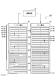
- FIG. 2 is an explanatory diagram schematically showing the connection of each single cell of the secondary battery to which the welding quality inspection apparatus according to the embodiment of the present invention is applied.
- FIG. 3 is an exploded perspective view of a secondary battery to which the welding quality inspection apparatus according to the embodiment of the present invention is applied.
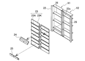
- FIG. 4 is an exploded perspective view of the bus bar unit of the secondary battery to which the welding quality inspection apparatus according to the embodiment of the present invention is applied.
- FIG. 5A is a perspective view showing a connection portion between an electrode tab and a bus bar of a secondary battery to which a welding quality inspection apparatus according to an embodiment of the present invention is applied.
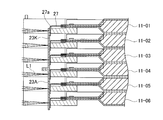
- FIG. 5B is a cross-sectional view showing a connection portion between the electrode tab and the bus bar of the secondary battery to which the welding quality inspection apparatus according to the embodiment of the present invention is applied.
- FIG. 6 is an explanatory diagram showing a state in which an electrode part and a bus bar are welded in a secondary battery to which the welding quality inspection apparatus according to the embodiment of the present invention is applied.
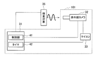
- FIG. 7 is a block diagram showing the configuration of the welding quality inspection apparatus according to the embodiment of the present invention.
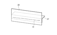
- FIG. 8A is a perspective view showing a welded portion between a bus bar and an electrode tab.
- FIG. 8B is a cross-sectional view showing the welded portion between the bus bar and the electrode tab.
- FIG. 9A is an explanatory diagram showing a case where welding at a welded portion is good.
- FIG. 9B is an explanatory diagram showing a case where welding at the welded portion is defective and is not welded.
- FIG. 9C is an explanatory diagram illustrating a case where welding at the welded portion is defective and molten metal is insufficient.
- FIG. 9D is an explanatory diagram illustrating a case where the weld in the welded portion is defective and porosity exists.
- FIG. 10 is a graph showing the temperature change of the welded portion over time after the start of energization. s1 shows the case where welding is favorable. s2 shows the case where it is not welded.
- FIG. 10 is a graph showing the temperature change of the welded portion over time after the start of energization. s1 shows the case where welding is favorable. s2 shows the case where it is not welded.
- FIG. 10 is a graph showing the temperature change of the welded portion over time
- FIG. 11 is a graph showing the temperature change of the welded portion over time after the start of energization.
- s3 shows the case where welding is favorable.
- s4 indicates a case where the molten metal is insufficient.
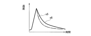
- FIG. 12 is a graph showing the temperature change of the welded portion over time after the start of energization.
- s5 shows the case where welding is favorable.
- s6 shows the case where porosity exists.
- FIG. 13 is a flowchart showing an operation procedure of the welding quality inspection apparatus according to the embodiment of the present invention.
- FIG. 14 is a diagram showing a result of determining the quality of welding using the welding quality inspection apparatus according to the embodiment of the present invention.
- FIG. 1 is a perspective view of a secondary battery in which a welding quality inspection apparatus according to an embodiment of the present invention is employed
- FIG. 2 is an explanatory diagram schematically showing an electrical connection state of the secondary battery. It is.
- a secondary battery 100 includes an assembled battery 12 in which a plurality of flat unit cells 11 (11-01 to 11-21) are stacked in the thickness direction (21 in the figure). .
- each single battery 11 is arranged so that the positive electrode and the negative electrode are switched every three sheets. That is, the upper three cells 11-01 to 11-03 have a positive pole on the right side and a negative pole on the left side, and the lower three cells 11-04 to 11-06 have a negative side on the right. The pole and the left side are positive. Similarly, the polarity is reversed every three sheets.
- the suffix “-01 to -21” is attached when the individual cells 11 are shown separately, and the suffix 11 is shown without any suffix when not distinguished.
- a protective cover 13 is provided on the front surface of the battery pack 12, an upper pressure plate 14 is provided on the upper surface, and a side plate 15 is provided on the side surface. Yes.
- FIG. 3 is an exploded perspective view showing a state in which the protective cover 13, the upper pressure plate 14, and the side plate 15 are removed.
- a bus bar unit 21 is provided between the front surface of the assembled battery 12 and the protective cover 13. Yes.
- FIG. 4 is an exploded perspective view showing a detailed configuration of the bus bar unit 21.
- the bus bar unit 21 includes a bus bar holder 22 and a plurality of bus bars 23, and further includes a plus electrode 24 and a minus electrode 25.
- the bus bar holder 22 has a rectangular shape as a whole, and is divided into a left region X1 and a right region X2 by a column portion 22a provided at the center. Further, the left region X1 and the right region X2 are each provided with an insulating portion 26 for partitioning each unit cell 11.
- an insulating portion 26 is provided so as to partition 21 single cells 11 into 6, 6, 6, 3 from the upper side.
- an insulating portion 26 is provided so as to partition the 21 unit cells 11 from the upper side by 3, 6, 6, and 6.
- the bus bar 23 (23K, 23A) shown in FIG. 4 is composed of a flat plate-like conductor, and short-circuits the electrodes of the single cells 11 in the region partitioned by the insulating portion 26 of the bus bar holder 22.
- FIG. 5A and FIG. 5B are explanatory views showing a joint portion between the bus bar 23 (23K, 23A) and the electrode tab 27 of the unit cell 11, FIG. 5A is a perspective view, and FIG. 5B is a cross-sectional view. 5A and 5B show the joints of the upper six cells 11-01 to 11-06.
- An electrode tab 27 whose tip is bent in an L shape is provided at the end of the unit cell 11.
- the electrode tabs 27 of the upper three cells 11-01 to 11-03 are in surface contact with the bus bar 23K at the bent portions 27a at the tips.
- the electrode tabs 27 of the lower three cells 11-04 to 11-06 are in surface contact with the bus bar 23A at the bent portion 27a at the tip.
- the bus bars 23K and 23A are connected by welding or the like at the joint q1. Accordingly, the electrode tabs 27 of the upper three cells 11-01 to 11-03 and the electrode tabs 27 of the lower three cells 11-04 to 11-06 are electrically connected. Further, as described above, the polarities of the electrode tabs 27 of the upper three cells 11-01 to 11-03 and the polarities of the electrode tabs 27 of the lower three cells 11-04 to 11-06 are: Different. That is, one is a positive pole and the other is a negative pole. Therefore, by connecting the bus bars 23K and 23A as shown in FIG. 5 in each region of the bus bar holder 22 shown in FIG.
- each of the 21 single cells 11 (11 ⁇ 01 to 11-21) can be connected in 3 parallels and 7 series as shown in FIG.
- a plus electrode 24 is provided at the plus end
- a minus electrode 25 is provided at the minus end. Therefore, the assembled battery 12 can be charged by applying a DC voltage to the plus electrode 24 and the minus electrode 25. Further, by connecting a load to the plus electrode 24 and the minus electrode 25, a DC voltage can be supplied to the load.
- the electrode tab 27 is disposed inside the housing, and it is difficult to directly apply heat to the bent portion 27 a of the electrode tab 27. Therefore, there may be a case where the quality of welding cannot be determined with high accuracy.
- the secondary battery 100 is energized, and current is passed through the joint between the electrode tab 27 and the bus bar 23 which is a welded portion, thereby generating Joule heat, and the Joule heat generates heat to the welded portion.
- the welded part is photographed with an infrared camera, the temperature change of the welded part is measured, and the quality of the welding is determined based on the temperature change. Details will be described below.
- FIG. 7 is a block diagram showing the configuration of the welding quality inspection apparatus 101 according to this embodiment.
- the welding quality inspection apparatus 101 controls energization of the secondary battery 100 so that a current flows through the inspection target 35 (the welded portion between the electrode tab 27 and the bus bars 23K and 23A in FIG. 6).
- An energizing device 31 an infrared camera 32 that captures infrared light emitted from the inspection object 35, and a microcomputer 33 that analyzes an image captured by the infrared camera 32 and detects a temperature change of the inspection object 35.
- the microcomputer 33 has a function as a temperature detection unit that detects the temperature of the welded part.
- the microcomputer 33 can be configured as an integrated computer including a central processing unit (CPU), storage means such as RAM, ROM, and hard disk.
- CPU central processing unit
- storage means such as RAM, ROM, and hard disk.
- the energization device 31 includes a control unit 41 and a timer 42 that times the energization time.
- the control unit 41 performs control so that a desired current flows between the positive electrode 24 and the negative electrode 25 of the secondary battery 100 in a desired energization time.
- the control part 41 acquires the temperature data of the welding part at the time of electricity supply, and after electricity supply from the microcomputer 33, and determines the quality of welding based on the temperature change of a welding part. That is, the energization device 31 has a function as a heat input part that inputs heat into the welded part. Furthermore, when the welding is defective, the control unit 41 estimates the type of defect.
- control unit 41 has a function as a welding determination unit that determines the quality of welding based on the temperature change of the welded portion due to energization.
- the control unit 41 can be configured as an integrated computer including a central processing unit (CPU) and storage means such as a RAM, a ROM, and a hard disk.
- CPU central processing unit
- storage means such as a RAM, a ROM, and a hard disk.
- the secondary battery 100 When carrying out the inspection of the welding quality, the secondary battery 100 is energized by connecting the positive electrode 24 and the negative electrode 25 shown in FIG.
- the control part 41 measures the temperature change at this time from the image image
- a method for inspecting whether or not the welded portions of the electrode tabs 27 and the bus bars 23 are correctly welded using the welding quality inspection apparatus 101 illustrated in FIG. 7 will be described.
- a method is used in which heat is input to the inspection object 35 using a heat source, and further, a temperature change of the inspection object 35 is detected using an infrared camera 32 to determine whether the welding is good or bad.
- it is not easy to input heat into the welded portion, and it is difficult to inspect the quality of welding with high accuracy.
- the secondary battery 100 is discharged by conducting the positive electrode 24 and the negative electrode 25 of the secondary battery 100 using the energization device 31. Since electric current flows through the junction between the electrode tab 27 and the bus bar 23 due to the discharge, Joule heat is generated, thereby raising the temperature of the welded portion between the electrode tab 27 and the bus bar 23.
- the energization device 31 energizes a current of 100 A (preset current) for 15 seconds (predetermined time). This energization raises the temperature of the weld. Further, when energization is stopped, the increased temperature starts to decrease. In the present embodiment, the welded part is photographed with the infrared camera 32, and the temperature change with the passage of time of the welded part is measured.
- seam welding is performed by irradiating laser light from the bus bar 23 side at the joint between the electrode tab 27 and the bus bar 23.
- 8A and 8B are explanatory views schematically showing a welded portion, and as shown in FIG. 8A, a weld bead 51 is formed in the longitudinal direction of the bus bar 23. Further, as shown in FIG. 8B, the molten metal 52 penetrates from the bus bar 23 to the electrode tab 27.
- control part 41 classify
- the state of each defect will be described in detail.
- DELTA difference temperature
- the horizontal axis indicates time
- the vertical axis indicates the temperature of the welded portion
- the curve s1 indicates the temperature change when normally welded
- the curve s2 indicates the temperature when the welded portion is not welded. It shows a change.
- control part 41 sets the threshold value (this is made into 1st threshold value) of difference temperature previously, and when difference temperature (DELTA) (theta) is smaller than this 1st threshold value, it determines with unwelding.
- the control unit 41 sets a threshold value for the temperature increase rate (this is set as the second threshold value) in advance, and if the temperature increase rate is smaller than the second threshold value, the welded part is short of molten metal. to decide.
- the control unit 41 sets a threshold value for the temperature decrease rate (this is the third threshold value) in advance, and if the temperature decrease rate is smaller than the third threshold value, there is porosity in the weld.
- step S11 the operator sets the energizing current and energizing time of the secondary battery 100.
- the energization current is 100 A
- the energization time is 15 seconds.
- step S12 the energization device 31 is installed between the plus electrode 24 and the minus electrode 25, and energization is started.
- a current flows through a circuit connected to each unit cell 11, and a current flows through the welded portion between the bus bar 23 and the electrode tab 27.
- a current of 100 A flows for 15 seconds.
- the welded part is imaged by the infrared camera 32, and the microcomputer 33 measures the temperature of the welded part based on the image captured by the infrared camera 32.
- step S13 the microcomputer 33 determines whether the energization time (15 seconds) has elapsed.
- step S15 the control unit 41 compares the difference temperature ⁇ with the first threshold value.
- step S21 the control unit 41 determines that the welded portion is not welded. That is, as illustrated in FIG. 9B, the control unit 41 determines that the molten metal 52 of the bus bar 23 does not penetrate the electrode tab 27 and is not welded.
- step S16 the control unit 41 determines the temperature increase rate until the energization time (15 seconds) elapses. Is calculated.
- step S17 the control unit 41 determines whether or not the temperature increase rate is greater than the second threshold value. If the temperature increase rate is smaller than the second threshold value (NO in step S17), in step S22, the control unit 41 determines that the weld is insufficient for the molten metal. That is, as shown in FIG. 9C, the control unit 41 determines that the molten metal 52 of the bus bar 23 penetrates into the electrode tab 27, or the depth of penetration is shallow and the molten metal 52 is insufficient. To do.
- step S18 the control unit 41 calculates the temperature decrease rate after the temperature of the weld reaches the peak temperature.
- step S19 the control unit 41 determines whether or not the temperature decrease rate is greater than a third threshold value. If the temperature decrease rate is smaller than the third threshold (NO in step S19), in step S23, the control unit 41 determines that porosity (bubbles) exists in the welded portion. That is, as illustrated in FIG. 9D, the control unit 41 determines that the molten metal 52 of the bus bar 23 has penetrated to a deep position of the electrode tab 27 and that the porosity exists in the molten metal 52. .
- step S20 the control unit 41 determines that the weld is well welded. These determination results can be displayed on, for example, a display (not shown) or the like to notify the operator.
- the control unit 41 determines that the molten metal is insufficient. Further, in the sample N3, the differential temperature ⁇ was measured to be 5 ° C., the temperature rising rate was 0.3 [° C./second], and the temperature falling rate was ⁇ 0.05 [° C./second]. It is determined that porosity exists.
- control unit 41 can determine that a welding failure has occurred and the type of welding failure by making a determination in three stages.
- the welding quality inspection apparatus 101 when determining the quality of the welded portion, heat is input to the welded portion, and a temperature change due to the heat input is detected. And the welding quality inspection apparatus 101 determines the quality of welding based on a temperature change. Therefore, quality determination with high accuracy is possible.
- the welding quality inspection apparatus 101 calculates a difference temperature ⁇ between the temperature before the heat input of the welded portion and the temperature after the heat input, and based on the difference temperature ⁇ , whether or not the cause of the welding failure is unwelded. Determine whether. Therefore, the welding quality inspection apparatus 101 can recognize the detailed situation of welding failure. Further, when the difference temperature ⁇ is smaller than the first threshold value, the welding quality inspection apparatus 101 determines that the cause of the welding failure is non-welding, so that the state of the welding failure can be recognized with high accuracy. Become.
- the welding quality inspection apparatus 101 measures the temperature rise rate when heat is input to the welded portion, and determines whether or not the cause of the welding failure is a lack of molten metal based on the temperature rise rate. Thereby, the welding quality inspection apparatus 101 can recognize the detailed situation of welding failure. Moreover, since the welding quality inspection apparatus 101 determines that the weld metal is insufficient when the temperature increase rate is smaller than the second threshold value, it is possible to recognize the state of welding failure with high accuracy.
- the weld quality inspection apparatus 101 heats the weld and the temperature reaches the peak temperature, it measures the subsequent temperature decrease rate, and based on this temperature decrease rate, is there a porosity in the molten metal 52? Judge whether or not. Thereby, the welding quality inspection apparatus 101 can recognize the detailed situation of welding failure. Further, since the welding quality inspection apparatus 101 determines that porosity exists when the temperature decrease rate is smaller than the third threshold value, it is possible to recognize the state of welding failure with high accuracy.
- the welding quality inspection apparatus 101 first determines whether or not the differential temperature ⁇ is smaller than the first threshold, then determines whether or not the temperature rise rate is smaller than the second threshold, and finally determines the temperature. It is determined whether the descending speed is smaller than a third threshold value.
- the welding quality inspection apparatus 101 judges in the order of non-welding, weld metal shortage, and presence of porosity, that is, the degree of poor welding is worse. Thereby, the welding quality inspection apparatus 101 can judge the quality of welding, without overlooking that the condition of poor welding is worse.
- the welding quality inspection apparatus 101 can analyze the cause of the welding failure in more detail when the welding failure occurs, and can recognize the degree of the welding failure with high accuracy. For this reason, when a welding defect occurs, the welding quality inspection apparatus 101 can analyze the cause of the defect on the spot according to the situation and take a countermeasure.
- the welded portion is, for example, a joint portion between the electrode tab 27 and the bus bar 23. And this welding part is arrange
- energization by the secondary battery 100 is used as a method for inputting heat into the welded portion. That is, the welding quality inspection apparatus 101 according to the present embodiment, when inspecting the welding quality of the welded portion disposed inside the casing of the secondary battery 100, causes Joule heat generated by energizing the secondary battery 100. Heats the weld. Therefore, even when the welding quality inspection apparatus 101 cannot directly input heat into the welded portion from the outside, it can reliably input heat into the welded portion. Moreover, since this embodiment does not receive heat from an external heat source, it is not affected by reflection, and temperature variations can be suppressed. As a result, the welding quality inspection apparatus 101 can determine the quality of the welding quality with high accuracy.
- the welding quality inspection apparatus 101 determines whether or not the cause of the welding failure is unwelding based on the difference temperature ⁇ between the temperature before energization of the weld and the temperature after energization. Thereby, the welding quality inspection apparatus 101 can recognize the detailed situation of welding failure. Further, when the difference temperature ⁇ is smaller than the first threshold value, the welding quality inspection apparatus 101 determines that the cause of the welding failure is non-welding, so that the state of the welding failure can be recognized with high accuracy. Become.
- the welding quality inspection apparatus 101 measures the temperature rise rate when the welded portion is energized, and determines whether the cause of the welding failure is a lack of molten metal based on this temperature rise rate. Thereby, the welding quality inspection apparatus 101 can recognize the detailed situation of welding failure. Moreover, since the welding quality inspection apparatus 101 determines that the weld metal is insufficient when the temperature increase rate is smaller than the second threshold value, it is possible to recognize the state of welding failure with high accuracy.
- the welding quality inspection apparatus 101 measures the subsequent temperature decrease rate, and based on this temperature decrease rate, does the molten metal 52 have porosity? Judge whether or not. Thereby, the welding quality inspection apparatus 101 can recognize the detailed situation of welding failure. Further, since the welding quality inspection apparatus 101 determines that porosity exists when the temperature decrease rate is smaller than the third threshold value, it is possible to recognize the state of welding failure with high accuracy.
- the welding quality inspection apparatus 101 first determines whether or not the differential temperature is smaller than the first threshold, then determines whether or not the temperature increase rate is smaller than the second threshold, and finally the temperature decreases. It is determined whether or not the speed is smaller than a third threshold value.
- the welding quality inspection apparatus 101 judges in the order of non-welding, weld metal shortage, and presence of porosity, that is, the degree of poor welding is worse. Thereby, the welding quality inspection apparatus 101 can judge the quality of welding, without overlooking that the condition of poor welding is worse.
- the current is supplied by discharging the secondary battery 100 using the energization device 31, but the present invention is not limited to this, and other configurations within the housing of the secondary battery 100 are also possible. It is also possible to adopt a configuration in which heat is input to the weld using a heat source. Moreover, the welding quality inspection apparatus 101 can also input the heat into the welded portion using the current flowing when the secondary battery 100 is charged, measure the temperature of the welded portion at this time, and determine whether the welding is good or bad. .
- the welding quality inspection method and the welding quality inspection apparatus of the present invention have been described based on the illustrated embodiment, but the present invention is not limited to this, and the configuration of each part is an arbitrary function having the same function. It can be replaced with that of the configuration.
- the energization time is 15 seconds and the energization current is 100 A.
- the energization time and the energization current can be arbitrarily set.
- the quality inspection of the welded portion between the bus bar 23 and the electrode tab 27 has been described as an example.
- the present invention is not limited to this, and welding inside the casing of the secondary battery 100 is performed.
- the inspection method of the present invention can be applied to any part where a current flows.
Landscapes
- Engineering & Computer Science (AREA)
- Physics & Mathematics (AREA)
- Mechanical Engineering (AREA)
- Optics & Photonics (AREA)
- Plasma & Fusion (AREA)
- Life Sciences & Earth Sciences (AREA)
- Health & Medical Sciences (AREA)
- Chemical & Material Sciences (AREA)
- Analytical Chemistry (AREA)
- Biochemistry (AREA)
- General Health & Medical Sciences (AREA)
- General Physics & Mathematics (AREA)
- Immunology (AREA)
- Pathology (AREA)
- Connection Of Batteries Or Terminals (AREA)
Abstract
高精度に溶接の良否を判定することが可能な溶接部の溶接品質検査方法、及び溶接品質検査装置(101)を提供する。溶接品質検査装置(101)は、溶接部に入熱する入熱部(31)と、溶接部の温度を検出する温度検出部(33)と、入熱による溶接部の温度変化に基づいて溶接の良否を判定する溶接判定部(41)と、を備える。
Description
本発明は、溶接部における溶接の良否を検査する溶接品質検査方法、及び溶接品質検査装置に関する。
従来より、溶接の良否を検査する方法として、例えば特許文献1に開示されたものが知られている。特許文献1に開示された方法は、接合部に熱を加え、更に、赤外線カメラを用いて接合部を撮影し、赤外線画像より得られる赤外線強度に基づいて接合の良否を判定する。
しかしながら、上述した特許文献1に開示された従来例は、接合の良否を判定しているものの、不良と判定した場合に不良の状況、不良の程度を詳細に認識することができない。従って、不良と判定された際に、即時に修復することが難しいという問題があった。
本発明は、このような従来の課題を解決するためになされたものであり、その目的とするところは、高精度に溶接の良否を判定することが可能な溶接部の品質検査方法、及び品質検査装置を提供することにある。
上記目的を達成するため、本願発明は、溶接部に入熱し溶接部の時間経過に伴う温度変化に基づいて溶接の良否を判定する。
本願発明では、高精度に溶接の良否を判定することが可能となる。
以下、本発明の実施形態を図面に基づいて説明する。図1は、本発明の一実施形態に係る溶接品質検査装置が採用される二次電池の斜視図であり、図2は、該二次電池の電気的な接続状態を模式的に示す説明図である。
図1に示すように、二次電池100は、扁平形状の単電池11(11-01~11-21)を厚み方向に複数枚(図では、21枚)積層した組電池12を備えている。そして、図2に示すように各単電池11は、3枚毎にプラス極とマイナス極が入れ替わるように配置されている。即ち、上側の3枚の単電池11-01~11-03は、右側がプラス極、左側がマイナス極とされ、その下の3枚の単電池11-04~11-06は、右側がマイナス極、左側がプラス極とされている。以下同様に3枚ごとに極性が反転して配置されている。なお、以下では、単電池11を個々に区別して示す場合には、サフィックス「-01~-21」を付して示し、区別しない場合にはサフィックスを付さずに示すことにする。
図1に示すように、組電池12の前面には保護カバー13が設けられ、上面には上部加圧板14が設けられ、側面には側板15が設けられて全体が筐体形状に構成されている。
図3は、保護カバー13、上部加圧板14、及び側板15を取り外した様子を示す分解斜視図であり、組電池12の前面と保護カバー13との間には、バスバーユニット21が設けられている。
図4は、バスバーユニット21の詳細な構成を示す分解斜視図である。図4に示すように、バスバーユニット21は、バスバーホルダ22と複数のバスバー23を有し、更に、プラス電極24及びマイナス電極25を有している。バスバーホルダ22は全体が矩形状を成しており、中央に設けられる支柱部22aにより、左側領域X1と、右側領域X2に区分されている。更に、左側領域X1及び右側領域X2には、それぞれ各単電池11を仕切るための絶縁部26が設けられている。
左側領域X1においては、21枚の単電池11を、上側から6枚、6枚、6枚、3枚で仕切るように絶縁部26が設けられている。右側領域X2においては、21枚の単電池11を上側から、3枚、6枚、6枚、6枚で仕切るように絶縁部26が設けられている。このように絶縁部26を配設することにより、図2に示すように、21枚の単電池11を3直列、7並列に接続することができる。
図4に示すバスバー23(23K、23A)は平板形状の導電体で構成され、バスバーホルダ22の、絶縁部26で仕切られた領域の各単電池11の電極を短絡させる。
図5A、図5Bは、バスバー23(23K、23A)と単電池11の電極タブ27との接合部を示す説明図であり、図5Aは斜視図、図5Bは断面図を示している。図5A、図5Bでは上側の6枚の単電池11-01~11-06の接合部を示している。単電池11の端部には、先端部がL字状に屈曲した電極タブ27が設けられている。そして、上側の3枚の単電池11-01~11-03の電極タブ27は、先端の屈曲部27aにてバスバー23Kに面接触している。下側の3枚の単電池11-04~11-06の電極タブ27は、先端の屈曲部27aにてバスバー23Aに面接触している。
また、バスバー23Kと23Aは、接合部q1にて溶接等により連結される。従って、上側の3枚の単電池11-01~11-03の電極タブ27と、下側の3枚の単電池11-04~11-06の電極タブ27は、電気的に接続される。更に、前述したように上側の3枚の単電池11-01~11-03の電極タブ27の極性と、下側の3枚の単電池11-04~11-06の電極タブ27の極性は異なる。即ち、一方がプラス極で、他方がマイナス極となっている。従って、図4に示したバスバーホルダ22の、絶縁部26で仕切られた各領域で、図5で示したようにバスバー23K、23Aを接続することにより、21枚の各単電池11(11-01~11-21)を、図2に示すように3並列、7直列に接続することができる。そして、図1、図4に示したようにプラス側の端部には、プラス電極24が設けられ、マイナス側の端部には、マイナス電極25が設けられている。従って、プラス電極24とマイナス電極25に直流電圧を印加することにより、組電池12を充電することができる。更に、プラス電極24とマイナス電極25に負荷を接続することにより、該負荷に直流電圧を供給することができる。
上記のように構成された二次電池100では、図5A、図5Bに示したように、電極タブ27とバスバー23K、23Aを機械的且つ電気的に接続するために、溶接する必要がある。この場合、図6に示すように、バスバー23K、23Aの前面側(図中左側)からレーザ光L1を照射してシーム溶接、或いはスポット溶接する。こうすることにより、電極タブ27とバスバー23K、23Aを堅固に連結することができ、更に、電気的に導通させることができる。
また、電極タブ27の屈曲部27aとバスバー23K、23Aが正常に溶接されているか否かを判断するために、溶接品質を検査する必要がある。溶接品質の検査方法として、溶接部に熱源からの熱を加え、その後の溶接部の温度変化を測定して溶接の良否を判定する方法を採用することが通常行われる。しかし、図5A、図5Bに示したように、電極タブ27は、筐体の内部に配設されており、該電極タブ27の屈曲部27aに直接的に熱を加えることは難しい。従って、高精度に溶接の良否を判定できない場合がありうる。
本実施形態では、二次電池100を通電させ、溶接部である電極タブ27とバスバー23との接合部分に電流を流すことにより、ジュール熱を発生させて、このジュール熱により溶接部に熱を加える。更に、本実施形態は、この溶接部を赤外線カメラで撮影し、溶接部の温度変化を測定し、温度変化に基づいて溶接の良否を判定する。以下、詳細に説明する。
図7は、本実施形態に係る溶接品質検査装置101の構成を示すブロック図である。図7に示すように、溶接品質検査装置101は、検査対象35(図6の電極タブ27とバスバー23K、23Aとの溶接部)に電流が流れるように、二次電池100の通電を制御する通電装置31と、検査対象35より発せられる赤外光を撮影する赤外線カメラ32と、該赤外線カメラ32で撮影された画像を分析して、検査対象35の温度変化を検出するマイコン33を備えている。即ち、マイコン33は、溶接部の温度を検出する温度検出部としての機能を備えている。マイコン33は、例えば、中央演算ユニット(CPU)や、RAM、ROM、ハードディスク等の記憶手段からなる一体型のコンピュータとして構成することができる。
通電装置31は、制御部41と、通電時間を計時するタイマ42を備えている。制御部41は、二次電池100のプラス電極24とマイナス電極25の間に、所望の通電時間で、所望の電流が流れるように制御する。そして、制御部41は、通電時、及び通電後の、溶接部の温度データをマイコン33より取得し、溶接部の温度変化に基づいて、溶接の良否を判定する。即ち、通電装置31は、溶接部に入熱する入熱部としての機能を備えている。更に、制御部41は、溶接が不良である場合には、不良の種類を推定する。即ち、制御部41は、通電による溶接部の温度変化に基づいて、溶接の良否を判定する溶接判定部としての機能を備えている。該制御部41は、例えば、中央演算ユニット(CPU)や、RAM、ROM、ハードディスク等の記憶手段からなる一体型のコンピュータとして構成することができる。
溶接品質の検査を実施する場合には、通電装置31を用いて、図2に示すプラス電極24とマイナス電極25を接続して、二次電池100を通電させる。制御部41は、このときの温度変化を赤外線カメラ32で撮影された画像から測定し、通電時の温度変化に基づいて、検査対象35における溶接の良否を判定する。
以下、図7に示した溶接品質検査装置101を用いて、各電極タブ27とバスバー23との溶接部が正しく溶接されているか否かを検査する方法について説明する。従来における溶接の検査方法では、熱源を用いて検査対象35に入熱し、更に、赤外線カメラ32を用いて検査対象35の温度変化を検出し、溶接の良否を判定する方法が用いられている。しかし、上述したように、溶接部に入熱することが容易でなく、溶接の良否を高精度に検査することが難しい。
本実施形態では、二次電池100のプラス電極24とマイナス電極25を、通電装置31を用いて導通させることにより、二次電池100を放電させる。放電により、電極タブ27とバスバー23との接合部に電流が流れるので、ジュール熱が発生することにより、電極タブ27とバスバー23との間の溶接部の温度を上昇させる。
例えば、通電装置31により、100Aの電流(予め設定した電流)を、15秒間(所定時間)だけ通電する。この通電により溶接部の温度が上昇する。更に、通電が停止すると、上昇した温度が下降に転じる。本実施形態では、溶接部を赤外線カメラ32で撮影し、溶接部の時間経過に伴う温度変化を測定する。
以下、溶接部の温度変化と、溶接の良否、及び不良の状態について説明する。本実施形態では、図6に示したように、電極タブ27とバスバー23との接合部において、バスバー23側からレーザ光を照射してシーム溶接する。図8A、図8Bは、溶接部を模式的に示す説明図であり、図8Aに示すように、バスバー23の長手方向に溶接ビード51が形成される。また、図8Bに示すように、バスバー23から電極タブ27に溶融金属52が浸透する。
そして、制御部41は、溶融金属52の浸透状況に応じて、溶接部が未溶着、溶融金属不足、及びポロシティの発生、の3種類の不良に区分し、これらの不良を判別する。以下、各不良の状態について詳細に説明する。
[溶接部が未溶着の場合]
バスバー23と電極タブ27の接合部において、バスバー23側からレーザ溶接した際に、正常に溶接されている場合には、図9Aに示すように、バスバー23の溶融金属52が電極タブ27の内部まで浸透している。
バスバー23と電極タブ27の接合部において、バスバー23側からレーザ溶接した際に、正常に溶接されている場合には、図9Aに示すように、バスバー23の溶融金属52が電極タブ27の内部まで浸透している。
しかし、図9Bに示すように、バスバー23の溶融金属52が電極タブ27に届かず、溶接されていない状態、即ち、溶接部が未溶着の場合には、溶接部に通電したときの上昇温度が低下する。具体的には、マイコン33は、通電装置31による通電を開始する前の溶接部の温度θ1を測定し、100Aで15秒間通電した後の溶接部の温度θ2を測定し、双方の差分温度Δθ、即ち、Δθ=θ2-θ1を算出する。そして、制御部41は、差分温度Δθが予め設定した第1閾値よりも小さい場合には、溶接部が未溶着であると判断する。
図10は、横軸が時間を示し、縦軸が溶接部の温度を示し、曲線s1は正常に溶接されているときの温度変化を示し、曲線s2は溶接部が未溶着であるときの温度変化を示している。通電開始前の温度θ1に対して、通電装置31による通電を開始すると、正常に溶接されている場合には、θpまで温度が上昇する。また、未溶着である場合には、通電開始後に例えばθpよりも小さいθ2までしか温度は上昇しない。従って、未溶着である場合には、差分温度Δθ(θ2-θ1)は正常時と対比して小さくなる。即ち、(θp-θ1)>(θ2-θ1)となる。そして、制御部41は、予め差分温度の閾値(これを第1閾値とする)を設定し、差分温度Δθがこの第1閾値よりも小さい場合には、未溶着と判定する。
[溶接金属不足の場合]
図9Cに示すように、バスバー23の溶融金属52が電極タブ27の内部に浸透しているものの、電極タブ27内での溶融金属52が不足している場合には、θ2はθpに近づき、差分温度Δθは第1閾値よりも大きくなる可能性が高い。しかし、溶接部における温度上昇速度[℃/sec](単位時間当たりの上昇温度)が低下する。図11は、横軸が時間を示し、縦軸が溶接部の温度を示している。曲線s3は正常に溶接されているときの温度変化を示し、曲線s4は溶接金属が不足しているときの温度変化を示している。図11に示すように、正常な溶接の場合と対比して、溶融金属52が不足している場合には、曲線s4に示すように上昇速度が低下する(温度上昇時の傾きが緩やかになる)。従って、制御部41は、予め温度上昇速度の閾値(これを第2閾値とする)を設定し、温度上昇速度がこの第2閾値よりも小さい場合には、溶接部は溶融金属不足であると判断する。
図9Cに示すように、バスバー23の溶融金属52が電極タブ27の内部に浸透しているものの、電極タブ27内での溶融金属52が不足している場合には、θ2はθpに近づき、差分温度Δθは第1閾値よりも大きくなる可能性が高い。しかし、溶接部における温度上昇速度[℃/sec](単位時間当たりの上昇温度)が低下する。図11は、横軸が時間を示し、縦軸が溶接部の温度を示している。曲線s3は正常に溶接されているときの温度変化を示し、曲線s4は溶接金属が不足しているときの温度変化を示している。図11に示すように、正常な溶接の場合と対比して、溶融金属52が不足している場合には、曲線s4に示すように上昇速度が低下する(温度上昇時の傾きが緩やかになる)。従って、制御部41は、予め温度上昇速度の閾値(これを第2閾値とする)を設定し、温度上昇速度がこの第2閾値よりも小さい場合には、溶接部は溶融金属不足であると判断する。
[ポロシティが存在する場合]
図9Dに示すように、バスバー23の溶融金属52が電極タブ27の内部に深く浸透している場合には、上記の温度上昇速度は、第2閾値よりも大きくなる可能性が高い。しかし、溶融金属52内にポロシティ(気泡)が存在している場合には、通電が終了して溶接部の温度がピーク温度に達した後の、温度下降速度が低下する。図12は、横軸が時間を示し、縦軸が溶接部の温度を示している。曲線s5は正常に溶接されているときの温度変化を示し、曲線s6はポロシティが存在しているときの温度変化を示している。図12に示すように、正常な溶接の場合と対比して、ポロシティが存在している場合には、曲線s6に示すように溶接部の温度がピーク温度に達した後の温度下降速度が低下する(温度下降時の傾きが緩やかになる)。従って、制御部41は、予め温度下降速度の閾値(これを第3閾値とする)を設定し、温度下降速度がこの第3閾値よりも小さい場合には、溶接部にはポロシティが存在していると判断する。
図9Dに示すように、バスバー23の溶融金属52が電極タブ27の内部に深く浸透している場合には、上記の温度上昇速度は、第2閾値よりも大きくなる可能性が高い。しかし、溶融金属52内にポロシティ(気泡)が存在している場合には、通電が終了して溶接部の温度がピーク温度に達した後の、温度下降速度が低下する。図12は、横軸が時間を示し、縦軸が溶接部の温度を示している。曲線s5は正常に溶接されているときの温度変化を示し、曲線s6はポロシティが存在しているときの温度変化を示している。図12に示すように、正常な溶接の場合と対比して、ポロシティが存在している場合には、曲線s6に示すように溶接部の温度がピーク温度に達した後の温度下降速度が低下する(温度下降時の傾きが緩やかになる)。従って、制御部41は、予め温度下降速度の閾値(これを第3閾値とする)を設定し、温度下降速度がこの第3閾値よりも小さい場合には、溶接部にはポロシティが存在していると判断する。
次に、上述のように構成された本実施形態に係る溶接品質検査装置101の操作手順を、図13に示すフローチャートを参照して説明する。
初めに、ステップS11において、操作者は二次電池100の通電電流及び通電時間を設定する。一例として、通電電流を100Aとし、通電時間を15秒とする。
ステップS12において、図2に示すように、プラス電極24、マイナス電極25の間に通電装置31が設置され、通電が開始する。その結果、各単電池11に接続される回路に電流が流れ、ひいてはバスバー23と電極タブ27の溶接部に電流が流れる。具体的には、100Aの電流が15秒間流れる。また、赤外線カメラ32により溶接部が撮像され、更に、マイコン33は、赤外線カメラ32によって撮像された画像に基づいて、溶接部の温度を測定する。
ステップS13において、マイコン33は、通電時間(15秒)が経過したか否かを判断する。通電時間が経過した場合には、ステップS14において、マイコン33は、赤外線カメラ32で撮像された画像に基づいて、このときの溶接部の温度(これを、θ2とする)を検出する。更に、マイコン33は、通電開始前の温度(これをθ1とする)と、通電後の温度θ2との差分温度Δθ(=θ2-θ1)を算出する。
ステップS15において制御部41は、差分温度Δθと第1閾値とを比較する。差分温度Δθが第1閾値よりも小さい場合には(ステップS15でNO)、ステップS21において制御部41は、溶接部が未溶着であると判断する。即ち、図9Bに示したように、制御部41は、バスバー23の溶融金属52が電極タブ27に浸透しておらず、溶接されていない状態であると判断する。
一方、差分温度Δθが第1閾値よりも大きいと判断された場合には(ステップS15でYES)、ステップS16において制御部41は、通電時間(15秒)が経過するまでの間の温度上昇速度を算出する。
ステップS17において制御部41は、温度上昇速度が第2閾値よりも大きいか否かを判断する。そして、温度上昇速度が第2閾値よりも小さい場合には(ステップS17でNO)、ステップS22において制御部41は、溶接部が溶融金属不足であると判断する。即ち、図9Cに示したように、制御部41は、バスバー23の溶融金属52が電極タブ27内に浸透しているもの、浸透の深さが浅く溶融金属52が不足しているものと判断する。
また、上昇温度速度が第2閾値よりも大きい場合には(ステップS17でYES)、ステップS18において制御部41は、溶接部の温度がピーク温度に達した後の、温度下降速度を算出する。
ステップS19において制御部41は、温度下降速度が第3閾値よりも大きいか否かを判断する。そして、温度下降速度が第3閾値よりも小さい場合には(ステップS19でNO)、ステップS23において制御部41は、溶接部にポロシティ(気泡)が存在しているものと判断する。即ち、図9Dに示したように、制御部41は、バスバー23の溶融金属52が電極タブ27の深い位置まで浸透しているもの、溶融金属52内にポロシティが存在しているものと判断する。
下降温度速度が第3閾値よりも大きい場合には(ステップS19でYES)、ステップS20において制御部41は、溶接部は良好に溶接されているものと判断する。これらの判断結果は、例えばディスプレイ(図示省略)等に表示して操作者に通知することができる。
次に、具体的な上昇温度、温度上昇速度、及び温度下降速度と溶接不良種類との関係について、図14に示す説明図を参照して説明する。
図14において、サンプルN4のように溶接部の状態が良好である場合には、差分温度Δθは5℃、温度上昇速度は0.3[℃/秒]、温度下降速度は-0.1[℃/秒]である。そして、サンプルN1では、差分温度Δθが1℃と測定され、正常時の差分温度よりも低いので、制御部41は、溶接部は未溶着であると判定する。
また、サンプルN2では、差分温度Δθが5℃、温度上昇速度が0.15[℃/秒]と測定されたので、制御部41は、溶融金属不足と判定する。更に、サンプルN3では、差分温度Δθが5℃、温度上昇速度が0.3[℃/秒]、温度下降速度が-0.05[℃/秒]と測定されたので、制御部41は、ポロシティが存在していると判定する。
こうして、制御部41は、3つの段階で判定することにより、溶接不良が発生したこと、及び溶接不良の種類を特定することができるのである。
このようにして、本実施形態に係る溶接品質検査装置101では、溶接部の溶接品質の良否を判定する場合には、溶接部に入熱し、入熱による温度変化を検出する。そして、溶接品質検査装置101は、温度変化に基づいて、溶接の良否を判定する。従って、高精度な品質判定が可能となる。
また、溶接品質検査装置101は、溶接部の入熱前の温度と入熱後の温度の差分温度Δθを算出し、この差分温度Δθに基づいて、溶接不良の原因が未溶着であるか否かを判断する。従って、溶接品質検査装置101は、溶接不良の詳細な状況を認識することができる。また、溶接品質検査装置101は、差分温度Δθが第1閾値よりも小さい場合に、溶接不良の原因が未溶着であると判断するので、溶接不良の状況を高精度に認識することが可能となる。
更に、溶接品質検査装置101は、溶接部に入熱しているときの温度上昇速度を測定し、この温度上昇速度に基づいて溶接不良の原因が溶融金属不足であるか否かを判断する。これにより、溶接品質検査装置101は、溶接不良の詳細な状況を認識することができる。また、溶接品質検査装置101は、温度上昇速度が第2閾値よりも小さい場合に、溶接金属不足であると判断するので、溶接不良の状況を高精度に認識することが可能となる。
更に、溶接品質検査装置101は、溶接部に入熱して温度がピーク温度に達した場合に、その後の温度下降速度を測定し、この温度下降速度に基づいて溶融金属52にポロシティが存在するか否かを判断する。これにより、溶接品質検査装置101は、溶接不良の詳細な状況を認識することができる。また、溶接品質検査装置101は、温度下降速度が第3閾値よりも小さい場合に、ポロシティが存在すると判断するので、溶接不良の状況を高精度に認識することが可能となる。
更に、溶接品質検査装置101は、初めに差分温度Δθが第1閾値よりも小さいか否かを判断し、次いで、温度上昇速度が第2閾値よりも小さいか否かを判断し、最後に温度下降速度が第3閾値よりも小さいか否かを判断する。溶接品質検査装置101は、未溶着、溶接金属不足、ポロシティの存在、の順、即ち、溶接不良の度合いがより悪い順に判断する。これにより、溶接品質検査装置101は、溶接不良の状況がより悪いことを見逃すことなく、溶接の良否を判定することができる。
従って、溶接品質検査装置101は、溶接不良が発生した場合には、溶接不良の原因をより詳細に解析することができるので、溶接不良の程度を高精度に認識することができる。このため、溶接品質検査装置101は、溶接不良が発生した場合には、その状況に応じてその場で不良の原因を解析し、対応することが可能となる。
また、本実施形態において、溶接部は、例えば、電極タブ27とバスバー23との接合部分である。そして、この溶接部は、図5A、図5Bに示すように、二次電池100の筐体の内部に配設されている。また、本実施形態において、溶接部を入熱する方法として、二次電池100による通電を用いる。つまり、本実施形態に係る溶接品質検査装置101は、二次電池100の筐体の内部に配設された溶接部の溶接品質を検査する場合に、二次電池100を通電させることによるジュール熱により溶接部に入熱する。従って、溶接品質検査装置101は、外部から溶接部に直接的に入熱できない場合であっても、溶接部に確実に入熱することができる。また、本実施形態は、外部の熱源から入熱しないので、反射の影響を受けることがなく、温度のばらつきを抑制することができる。その結果、溶接品質検査装置101は、溶接品質の良否を高精度に判定することが可能となる。
更に、溶接品質検査装置101は、溶接部の通電前の温度と通電後の温度の差分温度Δθに基づいて、溶接不良の原因が未溶着で有るか否かを判断する。これにより、溶接品質検査装置101は、溶接不良の詳細な状況を認識することができる。また、溶接品質検査装置101は、差分温度Δθが第1閾値よりも小さい場合に、溶接不良の原因が未溶着であると判断するので、溶接不良の状況を高精度に認識することが可能となる。
更に、溶接品質検査装置101は、溶接部に通電しているときの温度上昇速度を測定し、この温度上昇速度に基づいて溶接不良の原因が溶融金属不足であるか否かを判断する。これにより、溶接品質検査装置101は、溶接不良の詳細な状況を認識することができる。また、溶接品質検査装置101は、温度上昇速度が第2閾値よりも小さい場合に、溶接金属不足であると判断するので、溶接不良の状況を高精度に認識することが可能となる。
更に、溶接品質検査装置101は、溶接部に通電して温度がピーク温度に達した場合に、その後の温度下降速度を測定し、この温度下降速度に基づいて溶融金属52にポロシティが存在するか否かを判断する。これにより、溶接品質検査装置101は、溶接不良の詳細な状況を認識することができる。また、溶接品質検査装置101は、温度下降速度が第3閾値よりも小さい場合に、ポロシティが存在すると判断するので、溶接不良の状況を高精度に認識することが可能となる。
更に、溶接品質検査装置101は、初めに差分温度が第1閾値よりも小さいか否かを判断し、次いで、温度上昇速度が第2閾値よりも小さいか否かを判断し、最後に温度下降速度が第3閾値よりも小さいか否かを判断する。溶接品質検査装置101は、未溶着、溶接金属不足、ポロシティの存在、の順、即ち、溶接不良の度合いがより悪い順に判断する。これにより、溶接品質検査装置101は、溶接不良の状況がより悪いことを見逃すことなく、溶接の良否を判定することができる。
なお、上記した実施形態では、通電装置31を用いて二次電池100を放電させて電流を流す構成としたが、本発明はこれに限定されず、二次電池100の筐体の内部における他の熱源を用いて溶接部に入熱する構成とすることも可能である。また、溶接品質検査装置101は、二次電池100の充電時に流れる電流を用いて溶接部に入熱し、このときの溶接部の温度を測定して、溶接の良否を判定することも可能である。
以上、本発明の溶接品質検査方法、及び溶接品質検査装置を図示の実施形態に基づいて説明したが、本発明はこれに限定されるものではなく、各部の構成は、同様の機能を有する任意の構成のものに置き換えることができる。
例えば、上述した実施形態では、21枚の単電池11を3並列、7直列に配置する例について説明したが、本発明はこれに限定されるものではなく、単電池の個数、並列、直列の個数は任意に設定することができる。
また、上述した実施形態では、通電時間を15秒、通電電流を100Aとしたが、これは一例であり、通電時間、通電電流は任意に設定することが可能である。また、上述した実施形態では、バスバー23と電極タブ27との溶接部の品質検査を例に挙げて説明したが、本発明はこれに限定されず、二次電池100の筐体の内部の溶接部で、電流が流れる部位であれば、本発明の検査方法を適用することが可能である。
特願2016-204178号(出願日:2016年10月18日)及び特願2016-204181号(出願日:2016年10月18日)の全内容は、ここに援用される。
11(11-01~11-21) 単電池
12 組電池
13 保護カバー
14 上部加圧板
15 側板
21 バスバーユニット
22 バスバーホルダ
22a 支柱部
23(23K、23A) バスバー
24 プラス電極
25 マイナス電極
26 絶縁部
27 電極タブ
27a 屈曲部
31 通電装置
32 赤外線カメラ
33 マイコン
35 検査対象
41 制御部
42 タイマ
51 溶接ビード
52 溶融金属
100 二次電池
101 溶接品質検査装置
L1 レーザ光
q1 接合部
X1 左側領域
X2 右側領域
Δθ 差分温度
12 組電池
13 保護カバー
14 上部加圧板
15 側板
21 バスバーユニット
22 バスバーホルダ
22a 支柱部
23(23K、23A) バスバー
24 プラス電極
25 マイナス電極
26 絶縁部
27 電極タブ
27a 屈曲部
31 通電装置
32 赤外線カメラ
33 マイコン
35 検査対象
41 制御部
42 タイマ
51 溶接ビード
52 溶融金属
100 二次電池
101 溶接品質検査装置
L1 レーザ光
q1 接合部
X1 左側領域
X2 右側領域
Δθ 差分温度
Claims (18)
- 溶接部の品質を検査する溶接品質検査方法であって、
溶接部に入熱し、前記溶接部の、時間経過に伴う温度変化に基づいて溶接の良否を判定すること
を特徴とする溶接品質検査方法。 - 前記溶接部に入熱する前の温度と、入熱した後の温度との差分温度を算出し、前記差分温度に基づいて、前記溶接の良否を判定すること
を特徴とする請求項1に記載の溶接品質検査方法。 - 前記差分温度が、予め設定した第1閾値よりも小さいと判定されたとき、前記溶接部は未溶着であると判断すること
を特徴とする請求項2に記載の溶接品質検査方法。 - 前記溶接部に入熱した後の温度上昇速度に基づいて、前記溶接の良否を判定すること
を特徴とする請求項1に記載の溶接品質検査方法。 - 前記温度上昇速度が、予め設定した第2閾値よりも小さいと判定されたとき、前記溶接部は溶融金属不足であると判断すること
を特徴とする請求項4に記載の溶接品質検査方法。 - 前記溶接部に入熱して前記溶接部の温度がピーク温度に達した後の温度下降速度に基づいて前記溶接の良否を判定すること
を特徴とする請求項1に記載の溶接品質検査方法。 - 前記温度下降速度が、予め設定した第3閾値よりも小さいと判定されたとき、前記溶接部にポロシティが存在すると判断すること
を特徴とする請求項6に記載の溶接品質検査方法。 - 前記溶接部に入熱し、
前記溶接部の入熱前の温度と入熱後の温度の差分温度と、予め設定した第1閾値を比較し、差分温度が第1閾値よりも小さいと判定された場合には、前記溶接部は未溶着と判断し、
前記差分温度が前記第1閾値よりも大きい場合には、前記溶接部の入熱後の温度上昇速度と予め設定した第2閾値を比較し、温度上昇速度が第2閾値よりも小さいと判定された場合には、前記溶接部は溶融金属不足であると判断し、
前記温度上昇速度が第2閾値よりも大きい場合には、入熱して前記溶接部の温度がピーク温度に達した後の温度下降速度と予め設定した第3閾値を比較し、温度下降速度が第3閾値よりも小さいと判定された場合には、前記溶接部にポロシティが存在すると判断すること
を特徴とする請求項1に記載の溶接品質検査方法。 - 前記溶接部は、二次電池を構成する筐体の内部に配設され、
前記二次電池により前記溶接部に通電し、
前記通電による前記溶接部の温度変化に基づいて、溶接の良否を判定すること
を特徴とする請求項1に記載の溶接品質検査方法。 - 前記溶接部に通電する前の温度と、予め設定した電流で所定時間だけ通電した後の温度と、の差分温度に基づいて、前記溶接の良否を判定すること
を特徴とする請求項9に記載の溶接品質検査方法。 - 前記差分温度が、予め設定した第1閾値よりも小さいと判定されたとき、前記溶接部は未溶着であると判断すること
を特徴とする請求項10に記載の溶接品質検査方法。 - 前記溶接部に通電した後の温度上昇速度に基づいて、前記溶接の良否を判定すること
を特徴とする請求項9に記載の溶接品質検査方法。 - 前記温度上昇速度が、予め設定した第2閾値よりも小さいと判定されたとき、前記溶接部は溶融金属不足であると判断すること
を特徴とする請求項12に記載の溶接品質検査方法。 - 前記溶接部に通電した後、通電を停止し、前記溶接部の温度がピーク温度に達した後の温度下降速度に基づいて前記溶接の良否を判定すること
を特徴とする請求項9に記載の溶接品質検査方法。 - 前記温度下降速度が、予め設定した第3閾値よりも小さいと判定されたとき、前記溶接部にポロシティが存在すると判断すること
を特徴とする請求項14に記載の溶接品質検査方法。 - 前記溶接部に、予め設定した電流で所定時間だけ通電し、
前記溶接部の通電前の温度と通電後の温度の差分温度と、予め設定した第1閾値を比較し、差分温度が第1閾値よりも小さいと判定された場合には、前記溶接部は未溶着と判断し、
前記差分温度が前記第1閾値よりも大きい場合には、前記溶接部の通電時の温度上昇速度と予め設定した第2閾値を比較し、温度上昇速度が第2閾値よりも小さいと判定された場合には、前記溶接部は溶融金属不足であると判断し、
前記温度上昇速度が第2閾値よりも大きい場合には、通電後の温度下降速度と予め設定した第3閾値を比較し、温度下降速度が第3閾値よりも小さいと判定された場合には、前記溶接部にポロシティが存在すると判断すること
を特徴とする請求項9に記載の溶接品質検査方法。 - 溶接部の品質を検査する溶接品質検査装置であって、
前記溶接部に入熱する入熱部と、
前記溶接部の温度を検出する温度検出部と、
入熱による前記溶接部の温度変化に基づいて溶接の良否を判定する溶接判定部と、
を備えたことを特徴とする溶接品質検査装置。 - 前記溶接部は、二次電池を構成する筐体の内部に配設され、
前記二次電池により前記溶接部に通電する通電装置と、を備え、
前記溶接判定部は、前記通電による前記溶接部の温度変化に基づいて、溶接の良否を判定することを特徴とする請求項17に記載の溶接品質検査装置。
Applications Claiming Priority (4)
| Application Number | Priority Date | Filing Date | Title |
|---|---|---|---|
| JP2016204178 | 2016-10-18 | ||
| JP2016-204178 | 2016-10-18 | ||
| JP2016-204181 | 2016-10-18 | ||
| JP2016204181 | 2016-10-18 |
Publications (1)
| Publication Number | Publication Date |
|---|---|
| WO2018074161A1 true WO2018074161A1 (ja) | 2018-04-26 |
Family
ID=62018560
Family Applications (1)
| Application Number | Title | Priority Date | Filing Date |
|---|---|---|---|
| PCT/JP2017/034891 Ceased WO2018074161A1 (ja) | 2016-10-18 | 2017-09-27 | 溶接品質検査方法及び溶接品質検査装置 |
Country Status (1)
| Country | Link |
|---|---|
| WO (1) | WO2018074161A1 (ja) |
Cited By (10)
| Publication number | Priority date | Publication date | Assignee | Title |
|---|---|---|---|---|
| CN112834569A (zh) * | 2021-02-22 | 2021-05-25 | 上海展湾信息科技有限公司 | 一种实时检测焊接气孔的方法与设备 |
| KR20210065297A (ko) * | 2019-11-27 | 2021-06-04 | 주식회사 엘지에너지솔루션 | 열화상 감지를 이용한 용접부 검사방법 |
| KR20210127034A (ko) * | 2020-04-13 | 2021-10-21 | 주식회사 엘지화학 | 이차전지용 용접 검사장치 및 검사방법 |
| CN113791367A (zh) * | 2021-09-09 | 2021-12-14 | 湖北亿纬动力有限公司 | 一种检测电池极柱焊接效果的方法及检测装置 |
| CN114354677A (zh) * | 2020-09-29 | 2022-04-15 | 台达电子工业股份有限公司 | 焊锡制程监控系统及方法 |
| KR20220118244A (ko) * | 2021-02-18 | 2022-08-25 | 주식회사 엘지에너지솔루션 | Icb 모듈의 솔더링 불량 검출 방법 및 이를 포함하는 전지 모듈의 제조방법 |
| JP2023521313A (ja) * | 2020-07-15 | 2023-05-24 | エルジー エナジー ソリューション リミテッド | 電極リード折曲及び溶接装置及びこれを用いた電極リードの溶接方法 |
| JP2023541582A (ja) * | 2020-11-23 | 2023-10-03 | エルジー エナジー ソリューション リミテッド | バッテリーパックの診断方法 |
| CN116867602A (zh) * | 2021-04-21 | 2023-10-10 | 株式会社 Lg新能源 | 包括热成像相机的焊接检查装置 |
| JP2024510340A (ja) * | 2021-04-07 | 2024-03-06 | エルジー エナジー ソリューション リミテッド | 電極セル検査装置及び検査方法 |
Citations (5)
| Publication number | Priority date | Publication date | Assignee | Title |
|---|---|---|---|---|
| JPH08122051A (ja) * | 1994-10-21 | 1996-05-17 | Obara Kk | スポット溶接部のナゲット測定方法 |
| JP2003065985A (ja) * | 2001-08-28 | 2003-03-05 | Matsushita Electric Works Ltd | レーザー溶接部の検査方法及びその装置 |
| US20040081221A1 (en) * | 2001-01-26 | 2004-04-29 | Rolf Sandvoss | Thermography method |
| JP2015025147A (ja) * | 2013-07-24 | 2015-02-05 | 株式会社Uacj | アルミニウム合金製バスバー |
| JP2015064311A (ja) * | 2013-09-26 | 2015-04-09 | 株式会社日立ハイテクノロジーズ | 赤外線検査装置および赤外線検査方法 |
-
2017
- 2017-09-27 WO PCT/JP2017/034891 patent/WO2018074161A1/ja not_active Ceased
Patent Citations (5)
| Publication number | Priority date | Publication date | Assignee | Title |
|---|---|---|---|---|
| JPH08122051A (ja) * | 1994-10-21 | 1996-05-17 | Obara Kk | スポット溶接部のナゲット測定方法 |
| US20040081221A1 (en) * | 2001-01-26 | 2004-04-29 | Rolf Sandvoss | Thermography method |
| JP2003065985A (ja) * | 2001-08-28 | 2003-03-05 | Matsushita Electric Works Ltd | レーザー溶接部の検査方法及びその装置 |
| JP2015025147A (ja) * | 2013-07-24 | 2015-02-05 | 株式会社Uacj | アルミニウム合金製バスバー |
| JP2015064311A (ja) * | 2013-09-26 | 2015-04-09 | 株式会社日立ハイテクノロジーズ | 赤外線検査装置および赤外線検査方法 |
Cited By (27)
| Publication number | Priority date | Publication date | Assignee | Title |
|---|---|---|---|---|
| JP7527660B2 (ja) | 2019-11-27 | 2024-08-05 | エルジー エナジー ソリューション リミテッド | 熱画像感知を用いた溶接部検査方法 |
| KR20210065297A (ko) * | 2019-11-27 | 2021-06-04 | 주식회사 엘지에너지솔루션 | 열화상 감지를 이용한 용접부 검사방법 |
| CN113841045A (zh) * | 2019-11-27 | 2021-12-24 | 株式会社Lg新能源 | 使用热图像感测的焊接部分检查方法 |
| JP2022521584A (ja) * | 2019-11-27 | 2022-04-11 | エルジー エナジー ソリューション リミテッド | 熱画像感知を用いた溶接部検査方法 |
| CN113841045B (zh) * | 2019-11-27 | 2025-05-27 | 株式会社Lg新能源 | 使用热图像感测的焊接部分检查方法 |
| EP4006533A4 (en) * | 2019-11-27 | 2022-08-24 | Lg Energy Solution, Ltd. | WELD ZONE DETECTION PROCEDURE USING THERMAL IMAGING |
| US12292401B2 (en) | 2019-11-27 | 2025-05-06 | Lg Energy Solution, Ltd. | Weld portion inspection method using thermal image sensing |
| KR102741987B1 (ko) * | 2019-11-27 | 2024-12-13 | 주식회사 엘지에너지솔루션 | 열화상 감지를 이용한 용접부 검사방법 |
| KR20210127034A (ko) * | 2020-04-13 | 2021-10-21 | 주식회사 엘지화학 | 이차전지용 용접 검사장치 및 검사방법 |
| KR102889710B1 (ko) * | 2020-04-13 | 2025-11-21 | 주식회사 엘지에너지솔루션 | 이차전지용 용접 검사장치 및 검사방법 |
| JP2023521313A (ja) * | 2020-07-15 | 2023-05-24 | エルジー エナジー ソリューション リミテッド | 電極リード折曲及び溶接装置及びこれを用いた電極リードの溶接方法 |
| JP7570754B2 (ja) | 2020-07-15 | 2024-10-22 | エルジー エナジー ソリューション リミテッド | 電極リード折曲及び溶接装置及びこれを用いた電極リードの溶接方法 |
| CN114354677A (zh) * | 2020-09-29 | 2022-04-15 | 台达电子工业股份有限公司 | 焊锡制程监控系统及方法 |
| CN114354677B (zh) * | 2020-09-29 | 2025-08-15 | 台达电子工业股份有限公司 | 焊锡制程监控系统及方法 |
| US12228617B2 (en) | 2020-11-23 | 2025-02-18 | Lg Energy Solution, Ltd. | Method for diagnosing battery pack |
| JP7404590B2 (ja) | 2020-11-23 | 2023-12-25 | エルジー エナジー ソリューション リミテッド | バッテリーパックの診断方法 |
| JP2023541582A (ja) * | 2020-11-23 | 2023-10-03 | エルジー エナジー ソリューション リミテッド | バッテリーパックの診断方法 |
| KR102886230B1 (ko) * | 2021-02-18 | 2025-11-13 | 주식회사 엘지에너지솔루션 | Icb 모듈의 솔더링 불량 검출 방법 및 이를 포함하는 전지 모듈의 제조방법 |
| KR20220118244A (ko) * | 2021-02-18 | 2022-08-25 | 주식회사 엘지에너지솔루션 | Icb 모듈의 솔더링 불량 검출 방법 및 이를 포함하는 전지 모듈의 제조방법 |
| CN112834569A (zh) * | 2021-02-22 | 2021-05-25 | 上海展湾信息科技有限公司 | 一种实时检测焊接气孔的方法与设备 |
| JP7673226B2 (ja) | 2021-04-07 | 2025-05-08 | エルジー エナジー ソリューション リミテッド | 電極セル検査装置及び検査方法 |
| EP4287347A4 (en) * | 2021-04-07 | 2024-08-07 | LG Energy Solution, Ltd. | APPARATUS AND METHOD FOR INSPECTING AN ELECTRODE CELL |
| JP2024510340A (ja) * | 2021-04-07 | 2024-03-06 | エルジー エナジー ソリューション リミテッド | 電極セル検査装置及び検査方法 |
| JP7621715B2 (ja) | 2021-04-21 | 2025-01-27 | エルジー エナジー ソリューション リミテッド | 熱画像カメラを含む溶接検査装置 |
| JP2024507211A (ja) * | 2021-04-21 | 2024-02-16 | エルジー エナジー ソリューション リミテッド | 熱画像カメラを含む溶接検査装置 |
| CN116867602A (zh) * | 2021-04-21 | 2023-10-10 | 株式会社 Lg新能源 | 包括热成像相机的焊接检查装置 |
| CN113791367A (zh) * | 2021-09-09 | 2021-12-14 | 湖北亿纬动力有限公司 | 一种检测电池极柱焊接效果的方法及检测装置 |
Similar Documents
| Publication | Publication Date | Title |
|---|---|---|
| WO2018074161A1 (ja) | 溶接品質検査方法及び溶接品質検査装置 | |
| KR102640756B1 (ko) | 용착 상태 검출 방법 및 용착 상태 검출 장치 | |
| EP3511107B1 (en) | System and method for inspecting welding of secondary battery | |
| US4434351A (en) | Method and system for determining weld quality in resistance welding | |
| US12440926B2 (en) | Method and laser machining system for analyzing a weld seam formed by a laser welding process | |
| EP3868509B1 (en) | Laser welding method and laser welding monitoring system for a secondary battery | |
| KR20150003913A (ko) | 용접 방법, 용접 장치 및 전지의 제조 방법 | |
| US20130247672A1 (en) | Method and apparatus for non-destructive weld testing | |
| JP2013184225A (ja) | 抵抗溶接のモニタリング装置及びその方法とシステム | |
| JP5841626B2 (ja) | 片面抵抗溶接方法 | |
| KR102889710B1 (ko) | 이차전지용 용접 검사장치 및 검사방법 | |
| KR101390385B1 (ko) | 너트 프로젝션 용접의 용접품질 평가방법 | |
| US8395072B2 (en) | Resistance welding quality determination method and resistance welding quality determination apparatus | |
| CN115815769A (zh) | 用于电池的点底焊接的系统和监控方法 | |
| CN105891210A (zh) | 电阻焊点疲劳寿命的检测方法 | |
| KR102528477B1 (ko) | 용접 모니터링 장치 및 방법 | |
| JP7000932B2 (ja) | バッテリの異常箇所特定方法 | |
| KR102810924B1 (ko) | 이차전지 검사장치 및 검사방법 | |
| JP6107675B2 (ja) | 溶接品質検査方法と溶接品質検査装置 | |
| JP5224384B2 (ja) | 導体の溶接方法及びその溶接装置 | |
| CN118076887A (zh) | 焊接过程的质量监控 | |
| JPH07323376A (ja) | スタッドの抵抗溶接方法及び装置 | |
| US20260003006A1 (en) | Apparatus and Method for Inspecting Defect of Battery Cell, and System Comprising Same | |
| JPH0989825A (ja) | 抵抗溶接部の検査方法およびその装置 | |
| CN119260128A (zh) | 检查方法 |
Legal Events
| Date | Code | Title | Description |
|---|---|---|---|
| 121 | Ep: the epo has been informed by wipo that ep was designated in this application |
Ref document number: 17862106 Country of ref document: EP Kind code of ref document: A1 |
|
| NENP | Non-entry into the national phase |
Ref country code: DE |
|
| 122 | Ep: pct application non-entry in european phase |
Ref document number: 17862106 Country of ref document: EP Kind code of ref document: A1 |
|
| NENP | Non-entry into the national phase |
Ref country code: JP |