WO2018074061A1 - 空調装置 - Google Patents
空調装置 Download PDFInfo
- Publication number
- WO2018074061A1 WO2018074061A1 PCT/JP2017/030418 JP2017030418W WO2018074061A1 WO 2018074061 A1 WO2018074061 A1 WO 2018074061A1 JP 2017030418 W JP2017030418 W JP 2017030418W WO 2018074061 A1 WO2018074061 A1 WO 2018074061A1
- Authority
- WO
- WIPO (PCT)
- Prior art keywords
- ozone
- air conditioner
- electrode
- air
- sub
- Prior art date
Links
Images


Classifications
-
- F—MECHANICAL ENGINEERING; LIGHTING; HEATING; WEAPONS; BLASTING
- F24—HEATING; RANGES; VENTILATING
- F24F—AIR-CONDITIONING; AIR-HUMIDIFICATION; VENTILATION; USE OF AIR CURRENTS FOR SCREENING
- F24F7/00—Ventilation
- F24F7/003—Ventilation in combination with air cleaning
-
- B—PERFORMING OPERATIONS; TRANSPORTING
- B60—VEHICLES IN GENERAL
- B60H—ARRANGEMENTS OF HEATING, COOLING, VENTILATING OR OTHER AIR-TREATING DEVICES SPECIALLY ADAPTED FOR PASSENGER OR GOODS SPACES OF VEHICLES
- B60H3/00—Other air-treating devices
-
- B—PERFORMING OPERATIONS; TRANSPORTING
- B60—VEHICLES IN GENERAL
- B60H—ARRANGEMENTS OF HEATING, COOLING, VENTILATING OR OTHER AIR-TREATING DEVICES SPECIALLY ADAPTED FOR PASSENGER OR GOODS SPACES OF VEHICLES
- B60H3/00—Other air-treating devices
- B60H3/06—Filtering
-
- F—MECHANICAL ENGINEERING; LIGHTING; HEATING; WEAPONS; BLASTING
- F24—HEATING; RANGES; VENTILATING
- F24F—AIR-CONDITIONING; AIR-HUMIDIFICATION; VENTILATION; USE OF AIR CURRENTS FOR SCREENING
- F24F1/00—Room units for air-conditioning, e.g. separate or self-contained units or units receiving primary air from a central station
Definitions
- the present disclosure relates to an air conditioner that generates ozone and supplies conditioned air purified by the generated ozone.
- the air conditioner described in Patent Document 1 is a vehicle air conditioner mounted on a vehicle, and includes an ozone generation unit that generates ozone.
- This ozone generation part is arrange
- the ozone generator has two electrodes arranged opposite to each other, and a voltage application unit that applies a voltage between the two electrodes.
- This air conditioner generates ozone by applying a voltage between the two electrodes to cause discharge.
- the conditioned air passing through the ventilation path is purified (for example, deodorized, sterilized, etc.) by the generated ozone and provided to the passenger compartment.
- This disclosure is intended to provide a configuration that reduces the influence of ozone in an air conditioner that generates ozone.
- an air conditioner that supplies conditioned air that passes through a ventilation path includes an ozone generation unit that generates ozone that purifies the conditioned air that passes through the ventilation path, and removes the generated ozone from the conditioned air.
- the ozone generation unit includes a first electrode, a second electrode spaced from the first electrode, and a voltage application unit that generates ozone by applying a voltage between the first electrode and the second electrode. .
- the ozone removal part is arrange
- the conditioned air passing through the ventilation path can be purified (for example, deodorized, sterilized, etc.) by the ozone generated by the ozone generator.
- the ozone removal part arrange
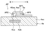
- FIG. 4 is an enlarged view showing a peripheral portion of a first electrode in the IV-IV cross section in FIG. 3.
- FIG. 5 is a diagram showing a VA-VA cross section in FIG. 4.
- FIG. 5 is a view showing a VB-VB cross section in FIG. 4.
- the air conditioner 1 according to the first embodiment of the present disclosure will be described with reference to FIGS. 1 to 5B.
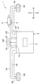
- the air conditioner 1 according to the present embodiment has a ventilation path AP through which conditioned air passes, and supplies conditioned air through the ventilation path AP.
- the air conditioner 1 is a vehicle air conditioner that is mounted on a vehicle and supplies conditioned air to the passenger compartment of the vehicle. Note that arrows f1 to f3 in FIG. 1 schematically show the flow of the conditioned air. In the drawings other than FIG. 4, the illustration of the voltage application unit 4ad is omitted.
- the air conditioner 1 includes a case 2, a blower 3, a cooler unit (not shown), a heater unit (not shown), an ozone generation unit 4, and an ozone removal unit 5.
- the blower 3, the cooler unit, the heater unit, the ozone generation unit 4, and the ozone removal unit 5 are disposed inside the case 2.
- the case 2 includes a ventilation path AP through which the conditioned air passes, an introduction port (not shown) for introducing outside air or inside air into the ventilation path AP, and three blowouts for blowing the conditioned air flowing through the ventilation path AP into the vehicle interior. Outlets 2a, 2b and 2c are formed. Outside air is air outside the vehicle compartment. The inside air is the air inside the passenger compartment of the vehicle.
- the air outlet 2a is an opening for blowing the conditioned air passing through the internal space of the duct 2d connected to the air outlet 2a (that is, a part of the ventilation path AP) from the grill G1 on the driver's seat side into the vehicle interior. It is.
- the air outlet 2b is an opening for blowing the conditioned air passing through the internal space of the duct 2e connected to the air outlet 2b (that is, a part of the ventilation path AP) from the passenger side grill G2 into the vehicle interior. It is.
- the air outlet 2c allows the conditioned air passing through the internal space of the duct 2f connected to the air outlet 2c (that is, a part of the ventilation path AP) to pass through the grill G3 located between the driver's seat and the passenger seat to the passenger compartment. It is an opening part for blowing out.
- the air conditioner 1 configured as described above introduces air into the ventilation path AP from the introduction port by the blower of the blower 3, cools it by the cooler unit, and in some cases, warms it by the heater unit, Supply cool or warm air into the passenger compartment. That is, all of the three ducts 2d to 2f are connected to the air outlets 2a to 2c for blowing the conditioned air toward the upper space in the vertical direction of the vehicle in the passenger compartment.
- the ducts 2d and 2e are so-called side face ducts.
- the ozone generator 4 is a device that generates ozone for purifying the conditioned air passing through the ventilation path AP.
- the ozone generation unit 4 has a configuration in which a plurality of ozone generation units 4 a shown in FIG. 3 are arranged.
- the ozone generator 4 has a total of 36 ozone generation units 4 a arranged in a rectangle of six vertically and six horizontally.
- each of the 36 ozone generation units 4a has a first electrode 4aa. Most of the first electrode 4aa is buried inside the dielectric substrate 4ac.
- the first electrode 4aa has five branch portions, and has a sub-electrode 40aa at the tip of each of the five branch portions.
- the first electrode 4aa has a plurality of sub-electrodes 40aa.
- each of the five sub electrodes 40aa is exposed to the outside of the dielectric substrate 4ac.
- each of the five sub electrodes 40aa is exposed to the purification space AP1.
- the purification space AP1 is a part of the ventilation path AP.
- Each of the plurality of sub-electrodes 40aa opposes a corresponding sub-removal portion 5a among a plurality of sub-removal portions 5a described later with a purification space AP1 interposed therebetween.
- Each of the 36 ozone generation units 4a includes a second electrode 4ab spaced from the first electrode 4aa and a dielectric substrate 4ac as shown in FIG.
- the first electrode 4aa and the second electrode 4ab are both made of a conductive material.
- the dielectric substrate 4ac is made of a dielectric material such as glass. As shown in FIG. 4, at least a part of the dielectric substrate 4ac is sandwiched between the first electrode 4aa and the second electrode 4ab.
- the ozone generation unit 4 includes a voltage application unit 4ad that applies a voltage between the first electrode 4aa and the second electrode 4ab in each of the 36 ozone generation units 4a.
- the voltage application unit 4ad generates ozone by applying a voltage between the first electrode 4aa and the second electrode 4ab to generate discharge.
- the ozone thus generated purifies the conditioned air passing through the ventilation path AP.
- the ozone generator 4 is configured such that the purification space AP1 is located above the center line in the vehicle vertical direction of the duct 2d in the internal space of the duct 2d. Yes.
- the ozone removing unit 5 is a member that removes ozone generated by the ozone generating unit 4 from the conditioned air. As shown in FIGS. 2 and 3, the ozone removing unit 5 includes a plurality of sub-removing units 5 a arranged corresponding to one body 1 on a plurality of sub-electrodes 40 aa.
- Each of the plurality of sub-removal units 5a is configured by a filter carrying activated carbon that decomposes ozone.
- the sub-removal unit 5a may be made of another material as long as it is a member that removes ozone from the conditioned air. That is, the sub-removal unit 5a may be configured of, for example, a filter supporting manganese dioxide that decomposes ozone, zeolite that adsorbs ozone, or silica gel.
- each of the plurality of sub-removal portions 5a has through-holes AP2, AP3, AP4, penetrating in a predetermined direction (that is, the horizontal direction in FIG. 4). It has a dome shape in which AP5 is formed. A space surrounded by the dome shape constitutes a purification space AP1. That is, each of the plurality of sub-removal portions 5a surrounds the purification space AP1.
- the through holes AP2, AP3, AP4, and AP5 are spaces that connect the purification space AP1 and a dome-shaped external space.
- the through holes AP2, AP3, AP4, and AP5 connect the purification space AP1 and the space on the opposite side of the ozone removal unit 5 to the purification space AP1 side in the ventilation path AP.
- the dome shape may be a hemispherical shape or a shape deviating from the hemispherical shape.
- the conditioned air flows in the left-right direction in FIG. 3 in the ventilation path AP. That is, the conditioned air flows from the through hole AP2 to the through hole AP3 or from the through hole AP3 to the through hole AP2.
- Each of the plurality of sub-removal portions 5a is disposed on the surface 4ca on the side where the first electrode 4aa is disposed in the corresponding dielectric substrate 4ac.
- the ozone removing unit 5 is disposed to face the sub electrode 40aa across the purification space AP1 that is a part of the ventilation path AP.
- the ozone removing unit 5 includes a plurality of sub-removing units 5a corresponding to the plurality of sub-electrodes 40aa on a one-to-one basis.
- the purification space AP1 is a part of the internal space of the duct 2d.
- each of the plurality of sub-removal portions 5a has one end of the first electrode 4aa in a direction parallel to the surface 4ca on the side where the sub-electrode 40aa is disposed in the dielectric substrate 4ac.
- the sub removal portion 5a is formed so that the purification space AP1 surrounds the entire surface of the sub electrode 40aa on the ventilation path AP side.
- the direction parallel to the surface 4ca is a direction parallel to the paper surface of FIGS. 5A and 5B.
- each of the 36 ozone generation units 4a is provided with one or more sub-removal units 5a. More specifically, one sub-removal portion 5a is provided corresponding to each of the plurality of sub-electrodes 40aa provided in the ozone generation unit 4a. Two or more sub-removal portions 5a may be provided corresponding to each of the plurality of sub-electrodes 40aa.
- the ozone removing unit 5 is configured such that the purification space AP1 is located above the center line in the vehicle vertical direction in the internal space of the duct 2d.
- the purification space AP1 extends along the direction in which the duct 2d extends (that is, the vehicle left-right direction) It is configured.
- the air conditioner 1 includes the ozone removing unit 5 that removes ozone from the conditioned air. And each of the some sub removal part 5a which comprises this ozone removal part 5 is arrange
- the conditioned air passing through the ventilation path AP can be purified (for example, deodorized, sterilized, etc.) by the ozone generated by the ozone generator 4.
- the ozone contained in the conditioned wind which passes along purification space AP1 is provided by providing the sub removal part 5a arrange
- each sub-removal portion 5a surrounds the purification space AP1 and has through holes AP2, AP3, AP4, and AP5.
- through-hole AP2, AP3, AP4, AP5 connects the space on the opposite side to purification
- the conditioned air introduced into the purification space AP1 from the through holes AP2, AP3, AP4, AP5 can be purified by ozone generated by the ozone generator 4. And in purification space AP1, ozone can be efficiently removed by the sub removal part 5a, and it can blow out from through-hole AP2, AP3, AP4, AP5.
- the corresponding sub-removal portion 5a is configured so that the purification space AP1 covers and surrounds the entire surface of the sub-electrode 40aa on the ventilation path AP side.
- the purification space AP1 is a space around each sub-removal portion 5a, and in particular, is a space sandwiched between sub-electrodes 40aa corresponding to each sub-removal portion 5a.
- the ozone generated around the sub electrode 40aa or the sub electrode 40aa can be more reliably removed by the sub removing unit 5a.
- the ozone removing unit 5 has a plurality of sub-removing units 5a corresponding to the plurality of sub-electrodes 40aa on a one-to-one basis.
- Each of the plurality of sub-electrodes 40aa is opposed to the corresponding sub-removal unit 5a among the plurality of sub-removal units 5a with the purification space AP1 interposed therebetween.
- ozone is surely easily removed from each of the plurality of sub-electrodes 40aa, and the influence on the occupant's human body and the like can be further alleviated.
- the air conditioner 1 is a vehicle air conditioner that is mounted on a vehicle and supplies conditioned air to the passenger compartment of the vehicle.
- ozone is suppressed from being transported to the passenger compartment or the like, and the influence on the human body of the occupant can be mitigated.
- the ventilation path AP is an internal space of the duct 2d connected to the air outlet 2a that blows the conditioned air toward the upper space in the vehicle vertical direction in the vehicle compartment.
- the air conditioner 1 it is possible to purify the conditioned air that goes to the upper body (for example, the face) of the passenger. Moreover, the ozone contained in the conditioned air that goes to the upper body (for example, the face) of the occupant can be reduced. Thereby, the air conditioner 1 which concerns on this embodiment contributes to alleviation of the influence on a passenger
- the ozone generation unit 4 and the ozone removal unit 5 are configured so that the purification space AP1 is positioned above the center line in the vehicle vertical direction of the duct 2d in the internal space of the duct 2d.
- water existing in the internal space of the duct 2d can be prevented from adhering to the ozone generation unit 4 (for example, the first electrode 4aa) or the ozone removal unit 5.
- the ozone generation unit 4 and the ozone removal unit 5 are configured such that the purification space AP1 extends along the direction in which the duct 2d extends (that is, the vehicle left-right direction).
- the ventilation resistance of the conditioned air passing through the vicinity of the ozone generating unit 4 and the ozone removing unit 5 is reduced, and a decrease in the wind speed of the conditioned air can be reduced.
- a filter carrying activated carbon or manganese dioxide is employed as one specific example of the sub-removal unit 5a.
- the ozone generation unit 4 and the ozone removal unit 5 are configured such that the purification space AP1 is positioned above the vehicle vertical direction in the internal space of the duct 2d.
- the ozone generation unit 4 and the ozone removal unit 5 are configured such that the purification space AP1 is positioned below the vehicle vertical direction in the internal space of the duct 2d. You may do it. In this case, a specific effect by arranging the ozone generation unit 4 and the ozone removal unit 5 on the upper side cannot be obtained, but the other effects described in the first embodiment can be obtained.
- the sub-removal part 5a is formed so that the purification space AP1 surrounds the entire surface of the sub-electrode 40aa on the ventilation path AP side.
- the sub-removal portion 5a may be formed so that the purification space AP1 surrounds a part of the surface of the sub-electrode 40aa on the ventilation path AP side. In this case, a specific effect obtained by forming the sub removal portion 5a so as to surround the entire surface of the sub electrode 40aa on the ventilation path AP side cannot be obtained, but other effects described in the first embodiment are not obtained. can get.
- a configuration may be adopted in which a plurality of devices each composed of the ozone generation unit 4 and the ozone removal unit 5 in the first embodiment are stacked. In this case, the effect of ozone purification and ozone removal can be particularly enhanced.
- the ozone generator 4 and the ozone remover 5 in the first embodiment are replaced with the evaporator 6 in the purification space AP1. It may be arranged on the upstream side of the flow of conditioned air. In this case, ozone purification by the ozone generator 4 can prevent the odor due to ozone from accumulating in the evaporator 6. Note that an arrow f4 in FIG. 9 schematically shows the flow of the conditioned air.
- the deodorizing filter 7 which is arrange
- the odor component adsorbed by the deodorizing filter 7 can be decomposed by ozone generated by the discharge of the first electrode 4aa. Thereby, the lifetime of the deodorizing filter 7 can be lengthened.
- an arrow f5 in FIG. 10 schematically shows the flow of the conditioned air.
- the ozone generator 4 and the ozone remover 5 in the first embodiment are arranged at the outlet 2 g for blowing conditioned air from the inside of the air conditioner 1 to the outside. You may do it.
- an air conditioner that supplies conditioned air that has passed through a ventilation path includes an ozone generator that generates ozone that purifies the conditioned air that passes through the ventilation path;
- An ozone removing unit that removes generated ozone from the conditioned air is provided.
- the ozone generator includes a first electrode, a second electrode spaced from the first electrode, and a voltage applying unit that generates ozone by applying a voltage between the first electrode and the second electrode.
- the ozone removal part is arrange
- the ozone removing unit surrounds the purification space and has a through hole. And a through-hole connects the space on the opposite side to the purification
- the conditioned air introduced into the space surrounded by the dome shape from the through hole can be purified by the ozone generated by the ozone generator. And, in the space surrounded by the dome shape, ozone can be efficiently removed by the ozone removing unit and can be blown out from the through hole.
- an ozone removal part makes the purification space surround the whole surface by the side of a ventilation passage among the 1st electrodes. Is formed.
- ozone generated around the first electrode or the first electrode can be more reliably removed by the ozone removing unit.
- the first electrode has a plurality of sub-electrodes.
- the ozone removing unit has a plurality of sub-removing units corresponding to the plurality of sub-electrodes on a one-to-one basis. Each of the plurality of sub-electrodes is opposed to the corresponding sub-removal portion among the plurality of sub-removal portions with a purification space interposed therebetween.
- ozone is surely easily removed from each of the plurality of sub-electrodes, and the influence on the human body of the occupant can be further alleviated.
- the air conditioner in the air conditioner according to any one of the first to fourth aspects, is mounted on a vehicle, and the vehicle interior of the vehicle is air-conditioned. It is a vehicle air conditioner that supplies wind.
- the ozone is suppressed from being transported into the passenger compartment and the like, and the influence on the human body of the occupant can be mitigated.
- the ventilation space blows out the conditioned air toward the upper space in the up-down direction of the vehicle in the passenger compartment. It is a part of the internal space of the duct connected to the air outlet.
- the sixth aspect it is possible to purify the conditioned air that goes to the upper body (for example, the face) of the passenger. Moreover, the ozone contained in the conditioned air that goes to the upper body (for example, the face) of the occupant can be reduced. This particularly contributes to mitigating the impact on the human body.
- a purification space is provided above the center line in the vehicle vertical direction of the duct in the internal space of the duct.
- the ozone generation unit and the ozone removal unit are configured to be positioned.
- the seventh aspect it is possible to prevent water existing in the internal space of the duct from adhering to the ozone generating part (for example, the first electrode) or the ozone removing part.
- the ozone generation unit and the ozone removal unit have a ventilation space extending in the direction of the duct. It is comprised so that it may extend along.
- the airflow resistance of the conditioned air passing through the vicinity of the ozone generating unit and the ozone removing unit is reduced, and the decrease in the wind speed of the conditioned air can be reduced.
- the vehicle air conditioner includes an evaporator for cooling the conditioned air.
- generation part is arrange
- the ninth aspect it is possible to prevent odors and the like due to ozone from accumulating in the evaporator by the purification of ozone by the ozone generator.
- the ozone removing unit is a filter supporting activated carbon or manganese dioxide.
- the air conditioner in any one viewpoint of 1st thru
- a deodorizing filter is provided.
- the odor component adsorbed on the deodorizing filter can be decomposed by ozone generated by the discharge of the first electrode. Thereby, the lifetime of a deodorizing filter can be lengthened.
Landscapes
- Engineering & Computer Science (AREA)
- Mechanical Engineering (AREA)
- Chemical & Material Sciences (AREA)
- Combustion & Propulsion (AREA)
- General Engineering & Computer Science (AREA)
- Air-Conditioning For Vehicles (AREA)
- Air Filters, Heat-Exchange Apparatuses, And Housings Of Air-Conditioning Units (AREA)
- Disinfection, Sterilisation Or Deodorisation Of Air (AREA)
Abstract
通風路(AP)を通った空調風を供給する空調装置は、前記通風路を通る前記空調風を浄化するオゾンを発生させるオゾン生成部(4)と、発生した前記オゾンを前記空調風から除去するオゾン除去部(5)と、を備える。前記オゾン生成部は、第1電極(4aa)と、前記第1電極から離間した第2電極(4ab)と前記第1電極と前記第2電極との間に電圧を印加することで前記オゾンを発生させる電圧印加部(4ad)と、を有する。前記オゾン除去部は、前記通風路の一部である浄化空間(AP1)を隔てて前記第1電極と対向して配置される。
Description
本出願は、2016年10月17日に出願された日本特許出願番号2016-203666号に基づくもので、ここにその記載内容が参照により組み入れられる。
本開示は、オゾンを発生し、発生したオゾンによって浄化した空調風を供給する空調装置に関する。
従来、オゾンを発生し、発生したオゾンによって浄化した空調風を供給する空調装置が提案されている。この種の空調装置としては、特許文献1に記載のものがある。
特許文献1に記載の空調装置は、車両に搭載される車両用空調装置であり、オゾンを発生するオゾン生成部を備えている。このオゾン生成部は、空調風を車室内に吹き出す吹出口に至るまでの通風路の途中に配置されている。このオゾン生成部は、互いに対向配置されている2つの電極と、この2つの電極間に電圧を印加する電圧印加部を有している。この空調装置は、この2つの電極間に電圧を印加し、放電を生じさせることで、オゾンを発生する。そして、この空調装置では、通風路を通る空調風を、発生したオゾンにより浄化(例えば、脱臭、殺菌など)し、車室内へ提供する。
しかしながら、本発明者の検討によれば、特許文献1に記載の空調装置などのオゾンを発生させる装置においては、オゾンによる乗員の体などへの影響が懸念される。
本開示は、オゾンを発生する空調装置において、オゾンによる影響を軽減する構成を提供することを目的とする。
本開示の1つの観点によれば、通風路を通った空調風を供給する空調装置は、通風路を通る空調風を浄化するオゾンを発生させるオゾン生成部と、発生したオゾンを空調風から除去するオゾン除去部と、を備える。そして、オゾン生成部は、第1電極と、第1電極から離間した第2電極と、第1電極と第2電極との間に電圧を印加することでオゾンを発生させる電圧印加部とを有する。そして、オゾン除去部は、通風路の一部である浄化空間を隔てて第1電極と対向して配置される。
このため、この空調装置では、オゾン生成部によって発生されたオゾンによって、通風路を通る空調風を浄化(例えば、脱臭、殺菌など)することができる。そして、浄化空間を隔てて第1電極と対向して配置されるオゾン除去部を備えることで、浄化空間を通る空調風に含まれるオゾンを、オゾン除去部によって除去することができる。これにより、オゾンが人の存する空間に運搬されることが抑制され、人体などへの影響を緩和することができる。
以下、本開示の実施形態について図に基づいて説明する。なお、以下の各実施形態相互において、互いに同一もしくは均等である部分には、同一符号を付して説明を行う。
(第1実施形態)
本開示の第1実施形態に係る空調装置1について図1~図5Bを参照して説明する。図1に示すように、本実施形態に係る空調装置1は、空調風を通す通風路APを有するとともに該通風路APを通った空調風を供給する。この空調装置1は、車両に搭載され、該車両の車室に空調風を供給する車両用空調装置である。尚、図1中の矢印f1~f3は、空調風の流れを模式的に示している。また、図4以外の図においては、電圧印加部4adの図示は省略してある。
本開示の第1実施形態に係る空調装置1について図1~図5Bを参照して説明する。図1に示すように、本実施形態に係る空調装置1は、空調風を通す通風路APを有するとともに該通風路APを通った空調風を供給する。この空調装置1は、車両に搭載され、該車両の車室に空調風を供給する車両用空調装置である。尚、図1中の矢印f1~f3は、空調風の流れを模式的に示している。また、図4以外の図においては、電圧印加部4adの図示は省略してある。
図1に示すように、本実施形態に係る空調装置1は、ケース2、送風機3、不図示のクーラユニット、および不図示のヒータユニット、オゾン生成部4、およびオゾン除去部5を有する。送風機3、クーラユニット、ヒータユニット、オゾン生成部4、およびオゾン除去部5は、ケース2の内部に配置される。
ケース2には、空調風を通す通風路AP、外気あるいは内気を通風路APに導入するための不図示の導入口、および通風路APを流れる空調風を車室内へ吹き出すための3個の吹出口2a、2b、2cが形成されている。外気は、車両の車室の外部の空気である。内気は、車両の車室の内部の空気である。
吹出口2aは、該吹出口2aに接続されているダクト2dの内部空間(すなわち、通風路APの一部)を通る空調風を、運転席側のグリルG1から車室内に吹き出すための開口部である。
吹出口2bは、該吹出口2bに接続されているダクト2eの内部空間(すなわち、通風路APの一部)を通る空調風を、助手席側のグリルG2から車室内に吹き出すための開口部である。
吹出口2cは、該吹出口2cに接続されているダクト2fの内部空間(すなわち、通風路APの一部)を通る空調風を、運転席と助手席の間に位置するグリルG3から車室内に吹き出すための開口部である。
このように構成されている空調装置1は、送風機3の送風により、空気を導入口から通風路APに導入し、クーラユニットによって冷却し、場合によってはヒータユニットによって暖めたのち、空調風としての冷風あるいは暖風を車室内に供給する。すなわち、3個のダクト2d~2fはいずれも、車室における車両の上下方向の上側の空間に向けて空調風を吹き出す吹出口2a~2cに繋げられる。ダクト2d、2eは、いわゆるサイドフェイスダクトである。
オゾン生成部4は、通風路APを通る空調風を浄化するオゾンを発生させる装置である。図2に示すように、オゾン生成部4は、図3に示すオゾン発生ユニット4aが複数並べられた構成とされている。具体的には、オゾン生成部4は、図2に示すように、縦に6個、横に6個の長方形に並べられた計36個のオゾン発生ユニット4aを有している。
図3に示すように、36個のオゾン発生ユニット4aの各々は、第1電極4aaを有している。第1電極4aaの大部分は、誘電体基盤4acの内部に埋没している。第1電極4aaは、5個の枝分かれ部を有し、該5個の枝分かれ部の各々の先端においてサブ電極40aaを有している。このように、本実施形態では、第1電極4aaは、複数のサブ電極40aaを有している。5個のサブ電極40aaの各々は、図4に示すように、誘電体基盤4acの外部に露出している。具体的には、5個のサブ電極40aaの各々は、浄化空間AP1に露出している。浄化空間AP1は、通風路APの一部の空間である。複数のサブ電極40aaの各々は、後述の複数のサブ除去部5aのうち対応するサブ除去部5aと、浄化空間AP1を隔てて対向している。また、36個のオゾン発生ユニット4aの各々は、図4に示すように、第1電極4aaから離間した第2電極4abと、誘電体基盤4acを有している。
第1電極4aaおよび第2電極4abはいずれも、導電性物質で構成されている。誘電体基盤4acは、ガラスなどの誘電体で構成されている。図4に示すように、誘電体基盤4acの少なくとも一部は、第1電極4aaと第2電極4abによって挟まれている。また、オゾン生成部4は、36個のオゾン発生ユニット4aの各々における第1電極4aaと第2電極4abとの間に電圧を印加する電圧印加部4adを備えている。
このように構成されているオゾン生成部4においては、電圧印加部4adが、第1電極4aaと第2電極4abとの間に電圧を印加して放電を発生させることで、オゾンを発生させる。このようにして発生したオゾンは、通風路APを通る空調風を浄化する。
また、図1に示すように、本実施形態では、オゾン生成部4は、ダクト2dの内部空間のうちダクト2dの車両上下方向中心線の上側に浄化空間AP1が位置するように、構成されている。
オゾン除去部5は、オゾン生成部4によって発生されたオゾンを空調風から除去する部材である。図2、図3に示すように、オゾン除去部5は、複数のサブ電極40aaに1体1に対応して配置された複数のサブ除去部5aで構成されている。
複数のサブ除去部5aの各々は、オゾンを分解する活性炭を担持したフィルタで構成されている。サブ除去部5aは、オゾンを空調風から除去する部材であれば、他の材料のもので構成されていても良い。すなわち、サブ除去部5aは、例えば、オゾンを分解する二酸化マンガンを担持したフィルタ、オゾンを吸着するゼオライトあるいはシリカゲルなどで構成されていても良い。
図4、図5A、図5Bに示すように、本実施形態では、複数のサブ除去部5aの各々は、所定方向(すなわち、図4における左右方向)に貫通する貫通孔AP2、AP3、AP4、AP5が形成されたドーム形状を有している。そして、このドーム形状によって囲まれている空間が、浄化空間AP1を構成している。すなわち、複数のサブ除去部5aの各々は、浄化空間AP1を囲んでいる。また、貫通孔AP2、AP3、AP4、AP5は、浄化空間AP1とドーム形状の外部の空間とを繋げる空間である。すなわち、本実施形態では、通風路APのうちオゾン除去部5の浄化空間AP1側とは反対側の空間と、浄化空間AP1とを、貫通孔AP2、AP3、AP4、AP5が繋げている。尚、ドーム形状は、半球形状であってもよいし、半球形状からずれた形状であってもよい。なお、空調風は、通風路AP内を、図3の左右方向に流れる。すなわち、空調風は、貫通孔AP2から貫通孔AP3へ流れるか、または、貫通孔AP3から貫通孔AP2へ流れる。
複数のサブ除去部5aの各々は、対応する誘電体基盤4acにおける第1電極4aaが配置されている側の面4caに配置されている。オゾン除去部5は、通風路APの一部である浄化空間AP1を隔ててサブ電極40aaと対向して配置されている。このように、オゾン除去部5は、複数のサブ電極40aaと1対1に対応する複数のサブ除去部5aを有している。尚、図1に示すように、浄化空間AP1は、ダクト2dの内部空間の一部である。
また、図5A、図5Bに示すように、複数のサブ除去部5aの各々は、誘電体基盤4acにおけるサブ電極40aaが配置された側の面4caに平行な方向において、第1電極4aaの一端から他端までの全体を囲むように、形成されている。具体的には、本実施形態では、サブ除去部5aは、浄化空間AP1がサブ電極40aaのうち通風路AP側の面の全体を囲むように、形成されている。尚、面4caに平行な方向は、図5A、図5Bの紙面に平行な方向である。
上記したように、本実施形態では、36個のオゾン発生ユニット4aの各々において、1個以上のサブ除去部5aが備えられている。より具体的には、オゾン発生ユニット4aに備えられている複数のサブ電極40aaの各々に対応して1個のサブ除去部5aが備えられている。尚、複数のサブ電極40aaの各々に対応して2個以上のサブ除去部5aが備えられていても良い。
また、図1に示すように、本実施形態では、オゾン除去部5は、ダクト2dの内部空間のうち車両上下方向中心線の上側に浄化空間AP1が位置するように、構成されている。
また、図1、図5A、図5Bに示すように、オゾン生成部4およびオゾン除去部5においては、浄化空間AP1がダクト2dの伸びる方向(すなわち、車両左右方向)に沿って伸びるように、構成されている。
以上で説明したように、本実施形態に係る空調装置1は、オゾンを空調風から除去するオゾン除去部5を備えている。そして、このオゾン除去部5を構成する複数のサブ除去部5aの各々は、通風路APの一部である浄化空間AP1を隔てて対応するサブ電極40aaと対向して配置されている。
このため、本実施形態に係る空調装置1では、オゾン生成部4によって発生されたオゾンによって、通風路APを通る空調風を浄化(例えば、脱臭、殺菌など)することができる。そして、本実施形態に係る空調装置1では、浄化空間AP1を隔ててサブ電極40aaと対向して配置されているサブ除去部5aを備えることで、浄化空間AP1を通る空調風に含まれるオゾンを、サブ除去部5aによって除去することができる。これにより、オゾンが人の存する空間に運搬されることが抑制され、人体などへの影響を緩和することができる。
また、本実施形態に係る空調装置1では、各サブ除去部5aは、浄化空間AP1を囲むと共に貫通孔AP2、AP3、AP4、AP5が形成されている。そして、通風路APのうちサブ除去部5aの浄化空間AP1側とは反対側の空間と、浄化空間AP1とを、貫通孔AP2、AP3、AP4、AP5が繋げている。
このため、本実施形態に係る空調装置1では、貫通孔AP2、AP3、AP4、AP5から浄化空間AP1に導入される空調風を、オゾン生成部4によって発生されるオゾンによって浄化することができる。そして、浄化空間AP1において、効率的にサブ除去部5aによってオゾンを除去することができ、貫通孔AP2、AP3、AP4、AP5から吹き出すことができる。
本実施形態では、各サブ電極40aaのうち通風路AP側の面の全体を浄化空間AP1が覆って囲むように、対応するサブ除去部5aが構成されている。なお、浄化空間AP1は、各サブ除去部5aの周囲の空間であり、特に、各サブ除去部5aと対応するサブ電極40aaによって挟まれた空間である。
このため、本実施形態に係る空調装置1では、サブ電極40aaあるいはサブ電極40aaの周囲にて発生されるオゾンを、より確実に、サブ除去部5aによって除去することができる。
また、オゾン除去部5は、複数のサブ電極40aaと1対1に対応する複数のサブ除去部5aを有している。そして、複数のサブ電極40aaの各々は、複数のサブ除去部5aのうち対応するサブ除去部5aと、浄化空間AP1を隔てて対向している。
このため、本実施形態に係る空調装置1では、複数のサブ電極40aaの各々について確実にオゾンが除去され易くなり、乗員の人体などへの影響をより緩和することができる。
また、本実施形態に係る空調装置1は、車両に搭載され、該車両の車室に空調風を供給する車両用空調装置である。
このため、本実施形態に係る空調装置1では、オゾンが車室内などに運搬されることが抑制され、乗員の人体などへの影響を緩和することができる。
また、本実施形態では、通風路APは、空調風を車室における車両上下方向の上側の空間に向けて吹き出す吹出口2aに繋げられるダクト2dの内部空間である。
このため、本実施形態に係る空調装置1では、乗員の上半身(例えば、顔)にいく空調風について、浄化を行うことができる。また、乗員の上半身(例えば、顔)にいく空調風に含まれるオゾンを少なくすることができる。これにより、本実施形態に係る空調装置1は、乗員の人体などへの影響の緩和に特に資する。
また、本実施形態では、ダクト2dの内部空間のうちダクト2dの車両上下方向中心線の上側に浄化空間AP1が位置するように、オゾン生成部4およびオゾン除去部5が構成されている。
このため、本実施形態に係る空調装置1では、ダクト2dの内部空間に存する水がオゾン生成部4(例えば、第1電極4aa)やオゾン除去部5に付着することを防止できる。
また、本実施形態では、オゾン生成部4およびオゾン除去部5は、浄化空間AP1がダクト2dの伸びる方向(すなわち、車両左右方向)に沿って伸びるように、構成されている。
このため、本実施形態に係る空調装置1では、オゾン生成部4およびオゾン除去部5の付近を通る空調風の通風抵抗が少なくなり、空調風の風速低下を軽減できる。
また、本実施形態では、サブ除去部5aの具体例の1つとして、活性炭あるいは二酸化マンガンを担持したフィルタを採用している。
(他の実施形態)
本開示は上記した実施形態に限定されるものではなく、適宜変更が可能である。
本開示は上記した実施形態に限定されるものではなく、適宜変更が可能である。
例えば、第1実施形態では、オゾン生成部4およびオゾン除去部5を、浄化空間AP1がダクト2dの内部空間のうち車両上下方向の上側に位置するように、構成していた。しかしながら、図6に示すように、第1実施形態において、オゾン生成部4およびオゾン除去部5を、浄化空間AP1がダクト2dの内部空間のうち車両上下方向の下側に位置するように、構成しても良い。この場合、オゾン生成部4およびオゾン除去部5を上側に配置することによる特有の効果は得られないが、第1実施形態にて説明したその他の効果は得られる。
また、第1実施形態では、サブ除去部5aを、浄化空間AP1がサブ電極40aaのうち通風路AP側の面の全体を囲むように、形成していた。しかしながら、図7、図8に示すように、サブ除去部5aを、浄化空間AP1がサブ電極40aaのうち通風路AP側の面の一部を囲むように、形成しても良い。この場合、サブ電極40aaのうち通風路AP側の面の全体を囲むようにサブ除去部5aを形成することによる特有の効果は得られないが、第1実施形態にて説明したその他の効果は得られる。
また、第1実施形態におけるオゾン生成部4およびオゾン除去部5で構成される一個の装置を、複数個積層した構成としても良い。この場合、オゾンの浄化およびオゾンの除去の効果を特に高くすることができる。
また、図9に示すように、空調風を冷却するための蒸発器6を備える空調装置1において、第1実施形態におけるオゾン生成部4およびオゾン除去部5を、浄化空間AP1のうち蒸発器6よりも空調風の流れの上流側に配置しても良い。この場合、オゾン生成部4によるオゾンの浄化によって、蒸発器6にオゾンによる臭気などが溜まることを防止できる。尚、図9中の矢印f4は、空調風の流れを模式的に示している。
また、図10に示すように、空調装置1の通風路APに配置されて空調風に含まれる臭い成分を吸着する脱臭フィルタ7を備える構成としても良い。この場合、第1電極4aaの放電によって発生されるオゾンにより、脱臭フィルタ7に吸着された臭い成分を分解することができる。これにより、脱臭フィルタ7の寿命を長くすることができる。尚、図10中の矢印f5は、空調風の流れを模式的に示している。
また、図11に示すように、空調装置1において、第1実施形態におけるオゾン生成部4およびオゾン除去部5を、該空調装置1の内部から外部へ空調風を吹き出すための吹出口2gに配置しても良い。
(まとめ)
上記各実施形態の一部または全部で示された第1の観点では、通風路を通った空調風を供給する空調装置は、通風路を通る空調風を浄化するオゾンを発生させるオゾン生成部と、発生したオゾンを空調風から除去するオゾン除去部を備える。そして、オゾン生成部は、第1電極と、第1電極から離間した第2電極と第1電極と第2電極との間に電圧を印加することでオゾンを発生させる電圧印加部を有する。そして、オゾン除去部は、通風路の一部である浄化空間を隔てて第1電極と対向して配置される。
上記各実施形態の一部または全部で示された第1の観点では、通風路を通った空調風を供給する空調装置は、通風路を通る空調風を浄化するオゾンを発生させるオゾン生成部と、発生したオゾンを空調風から除去するオゾン除去部を備える。そして、オゾン生成部は、第1電極と、第1電極から離間した第2電極と第1電極と第2電極との間に電圧を印加することでオゾンを発生させる電圧印加部を有する。そして、オゾン除去部は、通風路の一部である浄化空間を隔てて第1電極と対向して配置される。
上記各実施形態の一部または全部で示された第2の観点では、第1の観点における空調装置において、オゾン除去部は、浄化空間を囲むと共に貫通孔が形成されている。そして、通風路のうちオゾン除去部の浄化空間側とは反対側の空間と、浄化空間とを、貫通孔が繋げる。
この第2の観点によれば、貫通孔からドーム形状によって囲まれている空間に導入される空調風を、オゾン生成部によって発生されるオゾンによって浄化することができる。そして、ドーム形状によって囲まれている空間において、効率的にオゾン除去部によってオゾンを除去することができ、貫通孔から吹き出すことができる。
上記各実施形態の一部または全部で示された第3の観点では、第2の観点における空調装置において、オゾン除去部は、浄化空間が第1電極のうち通風路側の面の全体を囲むように、形成されている。
この第3の観点によれば、第1電極あるいは第1電極の周囲にて発生されるオゾンを、より確実に、オゾン除去部によって除去することができる。
上記各実施形態の一部または全部で示された第4の観点では、第1ないし3のいずれか1つの観点における空調装置において、第1電極は、複数のサブ電極を有する。また、オゾン除去部は、複数のサブ電極と1対1に対応する複数のサブ除去部を有する。そして、複数のサブ電極の各々は、複数のサブ除去部のうち対応するサブ除去部と、浄化空間を隔てて対向している。
この第4の観点によれば、複数のサブ電極の各々について確実にオゾンが除去され易くなり、乗員の人体などへの影響をより緩和することができる。
上記各実施形態の一部または全部で示された第5の観点では、第1ないし4のいずれか1つの観点における空調装置において、空調装置は、車両に搭載され、該車両の車室に空調風を供給する車両用空調装置である。
この第5の観点によれば、オゾンが車室内などに運搬されることが抑制され、乗員の人体などへの影響を緩和することができる。
上記各実施形態の一部または全部で示された第6の観点では、第5の観点における空調装置において、通風空間は、空調風を車室における車両の上下方向の上側の空間に向けて吹き出す吹出口に繋げられるダクトの内部空間の一部である。
この第6の観点によれば、乗員の上半身(例えば、顔)にいく空調風について、浄化を行うことができる。また、乗員の上半身(例えば、顔)にいく空調風に含まれるオゾンを少なくすることができる。これにより、乗員の人体などへの影響の緩和に特に資する。
上記各実施形態の一部または全部で示された第7の観点では、第5または6の観点における空調装置において、ダクトの内部空間のうち該ダクトの車両上下方向中心線の上側に浄化空間が位置するように、オゾン生成部およびオゾン除去部が構成されている。
この第7の観点によれば、ダクトの内部空間に存する水がオゾン生成部(例えば、第1電極)やオゾン除去部に付着することを防止できる。
上記各実施形態の一部または全部で示された第8の観点では、第5ないし7のいずれか1つの観点における空調装置において、オゾン生成部およびオゾン除去部は、通風空間がダクトの伸びる方向に沿って伸びるように、構成されている。
この第8の観点によれば、オゾン生成部およびオゾン除去部の付近を通る空調風の通風抵抗が少なくなり、空調風の風速低下を軽減できる。
上記各実施形態の一部または全部で示された第9の観点では、第5ないし8のいずれか1つの観点における空調装置において、車両用空調装置が、空調風を冷却するための蒸発器を有している。また、オゾン生成部が、通風空間のうち蒸発器よりも空調風の流れの下流側に配置されている。
この第9の観点によれば、オゾン生成部によるオゾンの浄化によって、蒸発器にオゾンによる臭気などが溜まることを防止できる。
上記各実施形態の一部または全部で示された第10の観点では、第1ないし9のいずれか1つの観点における空調装置において、オゾン除去部は、活性炭あるいは二酸化マンガンを担持したフィルタである。
上記各実施形態の一部または全部で示された第11の観点では、第1ないし10のいずれか1つの観点における空調装置において、通風路に配置されて空調風に含まれる臭い成分を吸着する脱臭フィルタを備えている。
この第11の観点によれば、第1電極の放電によって発生されるオゾンにより、脱臭フィルタに吸着された臭い成分を分解することができる。これにより、脱臭フィルタの寿命を長くすることができる。
Claims (11)
- 通風路(AP)を通った空調風を供給する空調装置であって、
前記通風路を通る前記空調風を浄化するオゾンを発生させるオゾン生成部(4)と、
発生した前記オゾンを前記空調風から除去するオゾン除去部(5)と、を備え、
前記オゾン生成部は、第1電極(4aa)と、前記第1電極から離間した第2電極(4ab)と前記第1電極と前記第2電極との間に電圧を印加することで前記オゾンを発生させる電圧印加部(4ad)と、を有し、
前記オゾン除去部は、前記通風路の一部である浄化空間(AP1)を隔てて前記第1電極と対向して配置される空調装置。 - 前記オゾン除去部は、前記浄化空間を囲むと共に貫通孔(AP2、AP3、AP4、AP5)が形成され、
前記通風路のうち前記オゾン除去部の前記浄化空間側とは反対側の空間と、前記浄化空間とを、前記貫通孔が繋げる請求項1に記載の空調装置。 - 前記浄化空間が前記第1電極のうち前記通風路側の面の全体を囲むように、前記オゾン除去部が形成されている請求項2に記載の空調装置。
- 前記第1電極は、複数のサブ電極(40aa)を有し、
前記オゾン除去部は、前記複数のサブ電極と1対1に対応する複数のサブ除去部(5a)を有し、
前記複数のサブ電極の各々は、前記複数のサブ除去部のうち対応する前記サブ除去部と、前記浄化空間を隔てて対向している請求項1ないし3のいずれか1つに記載の空調装置。 - 前記空調装置は、車両に搭載され、前記車両の車室に前記空調風を供給する車両用空調装置である請求項1ないし4のいずれか1つに記載の空調装置。
- 前記通風路は、前記空調風を前記車室における前記車両の上下方向の上側の空間に向けて吹き出す吹出口(2a)に繋げられるダクト(2d)の内部空間である請求項5に記載の空調装置。
- 前記ダクトの前記内部空間のうち前記ダクトの車両上下方向中心線の上側に前記浄化空間が位置するように、前記オゾン生成部および前記オゾン除去部が構成されている請求項6に記載の空調装置。
- 前記浄化空間が前記ダクトの伸びる方向に沿って伸びるように、前記オゾン生成部および前記オゾン除去部が構成されている請求項6または7のいずれか1つに記載の空調装置。
- 前記車両用空調装置は、前記空調風を冷却するための蒸発器(6)を有し、
前記オゾン生成部は、前記通風路のうち前記蒸発器よりも前記空調風の流れの上流側に配置されている請求項5ないし8のいずれか1つに記載の空調装置。 - 前記オゾン除去部は、活性炭あるいは二酸化マンガンを担持したフィルタである請求項1ないし9のいずれか1つに記載の空調装置。
- 前記通風路に配置されて前記空調風に含まれる臭い成分を吸着する脱臭フィルタ(7)を備えた請求項1ないし10のいずれか1つに記載の空調装置。
Applications Claiming Priority (2)
| Application Number | Priority Date | Filing Date | Title |
|---|---|---|---|
| JP2016-203666 | 2016-10-17 | ||
| JP2016203666A JP2019214217A (ja) | 2016-10-17 | 2016-10-17 | 空調装置 |
Publications (1)
| Publication Number | Publication Date |
|---|---|
| WO2018074061A1 true WO2018074061A1 (ja) | 2018-04-26 |
Family
ID=62019615
Family Applications (1)
| Application Number | Title | Priority Date | Filing Date |
|---|---|---|---|
| PCT/JP2017/030418 WO2018074061A1 (ja) | 2016-10-17 | 2017-08-24 | 空調装置 |
Country Status (2)
| Country | Link |
|---|---|
| JP (1) | JP2019214217A (ja) |
| WO (1) | WO2018074061A1 (ja) |
Citations (4)
| Publication number | Priority date | Publication date | Assignee | Title |
|---|---|---|---|---|
| JPS5076739A (ja) * | 1973-11-07 | 1975-06-23 | ||
| JPH07305883A (ja) * | 1994-05-11 | 1995-11-21 | Matsushita Refrig Co Ltd | 加湿装置 |
| JPH10138753A (ja) * | 1996-11-14 | 1998-05-26 | Zexel Corp | 車両用空気清浄装置 |
| JP2007112219A (ja) * | 2005-10-18 | 2007-05-10 | Denso Corp | 車両用屋上装着型空調装置 |
-
2016
- 2016-10-17 JP JP2016203666A patent/JP2019214217A/ja active Pending
-
2017
- 2017-08-24 WO PCT/JP2017/030418 patent/WO2018074061A1/ja active Application Filing
Patent Citations (4)
| Publication number | Priority date | Publication date | Assignee | Title |
|---|---|---|---|---|
| JPS5076739A (ja) * | 1973-11-07 | 1975-06-23 | ||
| JPH07305883A (ja) * | 1994-05-11 | 1995-11-21 | Matsushita Refrig Co Ltd | 加湿装置 |
| JPH10138753A (ja) * | 1996-11-14 | 1998-05-26 | Zexel Corp | 車両用空気清浄装置 |
| JP2007112219A (ja) * | 2005-10-18 | 2007-05-10 | Denso Corp | 車両用屋上装着型空調装置 |
Also Published As
| Publication number | Publication date |
|---|---|
| JP2019214217A (ja) | 2019-12-19 |
Similar Documents
| Publication | Publication Date | Title |
|---|---|---|
| JP4470710B2 (ja) | 車両用空気調和装置 | |
| JP5449244B2 (ja) | 車両用空調システム | |
| US10240808B2 (en) | Induced air discharging unit | |
| JP2008105613A (ja) | 車両用静電霧化装置 | |
| CN101623510A (zh) | 空气净化器 | |
| RU2286271C1 (ru) | Система вентиляции и кондиционирования воздуха железнодорожного вагона | |
| KR20070071571A (ko) | 음/양이온 발생기를 구비한 자동차용 공조장치 | |
| WO2018074061A1 (ja) | 空調装置 | |
| JP2010504244A (ja) | 車室用空気浄化装置 | |
| JP4848977B2 (ja) | 車両用浄化装置 | |
| KR101762804B1 (ko) | 차량의 공기조화 시스템 | |
| JP2007021100A (ja) | 空気清浄機 | |
| JP4881181B2 (ja) | 車両用浄化装置 | |
| KR100685728B1 (ko) | 자동차용 광촉매 공기 정화기 | |
| JP2008207633A5 (ja) | ||
| KR101384560B1 (ko) | 차량용 공조장치 | |
| US8500890B2 (en) | Air channel with integrated odor absorbing element | |
| KR101391154B1 (ko) | 차량용 이온발생장치 | |
| WO2014030539A1 (ja) | 空気調和機 | |
| JP2002362143A (ja) | 車両用香り発生装置 | |
| BR102014019097B1 (pt) | aparelho e sistema evaporativo direto com nebulização ultrassônica e ionização para tratamento de ar em climatização de ambientes | |
| JP5130148B2 (ja) | 車両用空調装置 | |
| WO2013008837A1 (ja) | フィルタユニット及びそれを備えた車両用空気調和装置 | |
| CN215474366U (zh) | 一种具有空气净化装置的汽车空调出风口 | |
| KR20070115037A (ko) | 차량용 공기조화시스템의 공기청정장치 |
Legal Events
| Date | Code | Title | Description |
|---|---|---|---|
| 121 | Ep: the epo has been informed by wipo that ep was designated in this application |
Ref document number: 17863130 Country of ref document: EP Kind code of ref document: A1 |
|
| NENP | Non-entry into the national phase |
Ref country code: DE |
|
| 122 | Ep: pct application non-entry in european phase |
Ref document number: 17863130 Country of ref document: EP Kind code of ref document: A1 |
|
| NENP | Non-entry into the national phase |
Ref country code: JP |