WO2018074058A1 - レーザー加工方法 - Google Patents
レーザー加工方法 Download PDFInfo
- Publication number
- WO2018074058A1 WO2018074058A1 PCT/JP2017/030239 JP2017030239W WO2018074058A1 WO 2018074058 A1 WO2018074058 A1 WO 2018074058A1 JP 2017030239 W JP2017030239 W JP 2017030239W WO 2018074058 A1 WO2018074058 A1 WO 2018074058A1
- Authority
- WO
- WIPO (PCT)
- Prior art keywords
- pulse
- peak intensity
- laser processing
- processing method
- region
- Prior art date
- Legal status (The legal status is an assumption and is not a legal conclusion. Google has not performed a legal analysis and makes no representation as to the accuracy of the status listed.)
- Ceased
Links
Images






Classifications
-
- B—PERFORMING OPERATIONS; TRANSPORTING
- B23—MACHINE TOOLS; METAL-WORKING NOT OTHERWISE PROVIDED FOR
- B23K—SOLDERING OR UNSOLDERING; WELDING; CLADDING OR PLATING BY SOLDERING OR WELDING; CUTTING BY APPLYING HEAT LOCALLY, e.g. FLAME CUTTING; WORKING BY LASER BEAM
- B23K26/00—Working by laser beam, e.g. welding, cutting or boring
-
- B—PERFORMING OPERATIONS; TRANSPORTING
- B23—MACHINE TOOLS; METAL-WORKING NOT OTHERWISE PROVIDED FOR
- B23K—SOLDERING OR UNSOLDERING; WELDING; CLADDING OR PLATING BY SOLDERING OR WELDING; CUTTING BY APPLYING HEAT LOCALLY, e.g. FLAME CUTTING; WORKING BY LASER BEAM
- B23K26/00—Working by laser beam, e.g. welding, cutting or boring
- B23K26/02—Positioning or observing the workpiece, e.g. with respect to the point of impact; Aligning, aiming or focusing the laser beam
- B23K26/06—Shaping the laser beam, e.g. by masks or multi-focusing
- B23K26/062—Shaping the laser beam, e.g. by masks or multi-focusing by direct control of the laser beam
- B23K26/0622—Shaping the laser beam, e.g. by masks or multi-focusing by direct control of the laser beam by shaping pulses
-
- B—PERFORMING OPERATIONS; TRANSPORTING
- B23—MACHINE TOOLS; METAL-WORKING NOT OTHERWISE PROVIDED FOR
- B23K—SOLDERING OR UNSOLDERING; WELDING; CLADDING OR PLATING BY SOLDERING OR WELDING; CUTTING BY APPLYING HEAT LOCALLY, e.g. FLAME CUTTING; WORKING BY LASER BEAM
- B23K26/00—Working by laser beam, e.g. welding, cutting or boring
- B23K26/50—Working by transmitting the laser beam through or within the workpiece
- B23K26/53—Working by transmitting the laser beam through or within the workpiece for modifying or reforming the material inside the workpiece, e.g. for producing break initiation cracks
-
- C—CHEMISTRY; METALLURGY
- C03—GLASS; MINERAL OR SLAG WOOL
- C03B—MANUFACTURE, SHAPING, OR SUPPLEMENTARY PROCESSES
- C03B23/00—Re-forming shaped glass
- C03B23/20—Uniting glass pieces by fusing without substantial reshaping
- C03B23/203—Uniting glass sheets
-
- C—CHEMISTRY; METALLURGY
- C03—GLASS; MINERAL OR SLAG WOOL
- C03C—CHEMICAL COMPOSITION OF GLASSES, GLAZES OR VITREOUS ENAMELS; SURFACE TREATMENT OF GLASS; SURFACE TREATMENT OF FIBRES OR FILAMENTS MADE FROM GLASS, MINERALS OR SLAGS; JOINING GLASS TO GLASS OR OTHER MATERIALS
- C03C23/00—Other surface treatment of glass not in the form of fibres or filaments
Definitions
- the present invention relates to a laser processing method.
- non-linear light absorption (multiphoton absorption) phenomenon is caused by condensing and irradiating ultra-short pulse laser light with extremely small pulse width, and heat is generated inside a transparent member such as glass.
- a method for forming a denatured region has been researched and developed (for example, see Patent Document 1).
- the laser processing method using nonlinear light absorption has the advantage that only the condensing region of the ultrashort pulse laser beam can be locally melted to form a heat-denatured region. For example, when joining two transparent members It's being used.
- the ultrashort pulse laser beam having a constant peak intensity is condensed and irradiated to the transparent member with high repetition.
- the periodic structural disturbance in the heat-denaturing region occurs for the following reason.
- the temperature of the condensing region rises due to the condensing irradiation of the ultrashort pulse laser beam, and the light absorption rate in the condensing region also increases.
- the ultrashort pulse laser beam having a constant peak intensity is repeatedly irradiated, the temperature of the condensing region tends to rise excessively.
- the temperature of the condensing region is excessively increased, the light absorption rate in the condensing region is rapidly decreased due to thermal denaturation of the transparent member.
- the light absorption rate is rapidly decreased, an excessive temperature rise in the light collecting region is temporarily relieved.
- the present invention devised to solve the above problems is a laser processing method in which ultra-short pulse laser light is condensed and irradiated to form a heat-denatured region in the condensing region inside the transparent member.
- the pulse laser light periodically changes in peak intensity, and the pulse train existing in one cycle of the change in peak intensity includes a maximum pulse with a maximum peak intensity, a minimum pulse with a minimum peak intensity, An intermediate pulse group including a plurality of pulses whose peak intensity gradually decreases from the maximum pulse side to the minimum pulse side between the maximum pulse and the minimum pulse.
- the transparent member is focused and irradiated with the ultrashort pulse laser light while periodically increasing or decreasing the peak intensity.
- the peak intensity itself decreases before the temperature of the condensing region rises excessively, thus preventing an excessive temperature rise in the condensing region and a decrease in light absorption rate associated therewith. be able to. Therefore, it is possible to suppress the periodic structural disturbance of the heat-denaturing region formed in the light condensing region, and it is difficult for distortion and cracking to occur in the heat-denaturing region and its periphery.
- the peak intensity of the minimum pulse is preferably 25% or more of the peak intensity of the maximum pulse. If it does in this way, it can prevent that the temperature of a condensing area
- the ultrashort pulse laser beam is intensity-modulated at a frequency of 1 kHz to 50 kHz.
- the period of change in the peak intensity of the ultrashort pulse laser light is about the same as the fluctuation period of the light absorption rate that can occur in the transparent member when the peak intensity of the ultrashort pulse laser light is kept constant. It may become. In this case, it is possible to more reliably suppress periodic fluctuations in the light absorption rate.
- the repetition frequency of the ultrashort pulse laser beam is preferably 100 kHz to 1 MHz. With such a high repetition frequency, the interval between adjacent pulses becomes narrow, so that the peak intensity can be smoothly changed almost continuously. Therefore, the temperature of the light collecting region can be controlled more precisely.
- the heat-denatured region may be formed linearly along the planned cutting line of the transparent member, and the transparent member may be cleaved by applying a tensile stress to the heat-denatured region.
- the transparent member is a laminate including the first member and the second member, the heat-denaturing region is formed at the interface between the first member and the second member, and the first member and the second member are joined. May be.
- the transparent member is preferably glass.
- a laser processing apparatus 1 is used in the laser processing method of the present embodiment.
- the laser processing apparatus 1 includes a laser light source 2 that outputs an ultrashort pulse laser beam L1 repeatedly, an acoustooptic device 3 as an intensity modulator that modulates the intensity of the ultrashort pulse laser beam L1 output from the laser light source 2, And a lens 4 for condensing the intensity-modulated ultrashort pulse laser beam L2.
- the laser light source 2 repeatedly outputs an ultrashort pulse laser beam L1 having a constant peak intensity.
- the ultrashort pulse laser beam L1 is composed of a pulse train P1 including a plurality of pulses Pa having a constant peak intensity.
- the ultrashort pulse laser beam L1 means one having a pulse width of 1 ⁇ 10 ⁇ 9 seconds or less.
- the pulse width of the ultrashort pulse laser beam L1 is preferably in the order of femtoseconds ( 10-15 seconds) to picoseconds ( 10-12 seconds) (for example, 10 picoseconds).
- the repetition frequency of the ultrashort pulse laser beam L1 is preferably 100 kHz to 1 MHz, and more preferably 500 kHz to 1 MHz.
- the acoustooptic device 3 modulates the intensity of the ultrashort pulse laser beam L1 based on the signal output from the oscillator 5 and outputs the ultrashort pulse laser beam L2.
- the intensity-modulated ultrashort pulse laser beam L2 is composed of a pulse train P2 including a plurality of pulses Pb whose peak intensity periodically changes.
- the modulation signal output from the oscillator 5 is a sine wave signal having a predetermined frequency.
- the intensity of the ultrashort pulse laser beam L1 is modulated at the frequency of the sine wave signal.
- the frequency (modulation frequency) of the modulation signal for intensity-modulating the ultrashort pulse laser beam L1 is preferably 1 kHz to 50 kHz.
- the repetition frequency of the ultrashort pulse laser beam L2 is the same as that of the ultrashort pulse laser beam L1 before intensity modulation.
- the intensity modulator is not limited to the acousto-optic element 3.
- the intensity of the ultrashort pulse laser beam output from the laser light source 2 may be modulated using an electro-optic effect, a magneto-optic effect, a thermo-optic effect, a non-linear optical effect, etc. May be directly input to output an ultrashort pulse laser beam whose intensity is modulated from the laser light source 2.
- the lens 4 condenses the intensity-modulated ultrashort pulse laser beam L2, and forms a condensing area CA inside the glass plate G as a transparent member.
- a transparent member means the member which permeate
- the ultrashort pulse laser beam L2 is incident from the first main surface Ga side.
- the incident surface of the ultrashort pulse laser beam L2 is not particularly limited.
- the heat-denaturing area HA is linearly formed inside the glass plate G at a position corresponding to the condensing area CA.
- the heat-denaturing region HA is formed along the planned cutting line of the glass plate G.
- the heat-denatured area HA is heated and cooled to generate a thermal stress, or a bending stress is generated around the heat-denatured area HA. Cleave G along the heat-denaturing zone HA.
- the spot diameter in the condensing area CA is preferably 0.5 to 2 ⁇ m. Moreover, it is preferable that the depth D from the 1st main surface Ga of heat-denaturing area
- the intensity-modulated ultrashort pulse laser light L2 is condensed and applied to the glass plate G with high repetition.
- the pulse train P2 constituting the ultrashort pulse laser beam L2 has a maximum pulse Pb1 that maximizes the peak intensity and a minimum peak intensity within the peak intensity change period (modulation signal period) Ts.
- an intermediate pulse group Pb3 including a plurality of pulses whose peak intensity gradually decreases from the maximum pulse Pb1 side toward the minimum pulse Pb2 side is included.
- the maximum pulse Pb1 exists at the head and tail in one cycle Ts, and the minimum pulse Pb2 exists at the center (corresponding to a half cycle) between the head and tail maximum pulses Pb1.
- the intermediate pulse group Pb3 exists between the leading maximum pulse Pb1 and the minimum pulse Pb2, and between the minimum pulse Pb2 and the trailing maximum pulse Pb1, respectively.
- the period Ts of change in peak intensity can be appropriately adjusted according to the thermal diffusivity of the glass plate G. For example, when the thermal diffusivity of the glass plate G is large, the cycle Ts is decreased, and when the thermal diffusivity of the glass plate G is small, the cycle Ts is increased.
- the frequency of the modulation signal (modulation frequency) is changed.
- the frequency of the modulation signal is changed in the range of 1 kHz to 50 kHz
- the period Ts is adjusted in the range of 0.02 ms to 1 ms.
- the peak intensity of the minimum pulse Pb2 is preferably 25% or more, more preferably 50% or more of the peak intensity of the maximum pulse Pb1.
- the peak intensity of the minimum pulse Pb2 is preferably 80% or less, more preferably 60% or less of the peak intensity of the maximum pulse Pb1.
- the glass plate G is focused and irradiated with the ultrashort pulse laser beam L2 whose peak intensity periodically increases and decreases. Due to the periodic increase / decrease of the peak intensity, the peak intensity itself is lowered before the temperature of the condensing area CA is excessively increased, and therefore, an excessive temperature increase of the condensing area CA can be prevented.
- the temporal change of the light absorption rate in the light collection area CA becomes very small, and the light absorption rate can be kept substantially constant. Therefore, for example, as shown in FIG. 7A, even when the glass plate G is soda-lime glass or when the glass plate G is non-alkali glass as shown in FIG. It is possible to suppress the occurrence of a disorder of the structure. As a result, the heat-denatured area HA becomes a dense line, and distortion and cracks are less likely to occur in the heat-denatured area HA and its surroundings.
- the laser light source is more effective than the case where the peak intensity of the ultrashort pulse laser beam L2 is condensed and irradiated while periodically increasing and decreasing the peak intensity while maintaining the peak intensity constant.
- the total output power of 2 can be increased.
- the laser processing conditions of the soda lime glass of FIG. 4A which is a comparative example are (1) light source: LD excitation Nd: YAG picosecond pulse laser, (2) wavelength: 1064 nm, (3) repetition frequency: 500 kHz, ( 4) Average output: 6 W, (5) Pulse width: 0.028 ns, (6) Spot diameter: 1 ⁇ m, (7) Scan speed: 10 mm / s. Moreover, the laser processing conditions of the alkali-free glass of FIG.
- 4B which is a comparative example are (1) light source: LD excitation Nd: YAG picosecond pulse laser, (2) wavelength: 1064 nm, (3) repetition frequency: 500 kHz, (4 ) Average output: 8 W, (5) Pulse width: 0.028 ns, (6) Spot diameter: 1 ⁇ m, (7) Scan speed: 10 mm / s.
- the laser processing conditions of the soda lime glass of FIG. 7A are (1) light source: LD excitation Nd: YAG picosecond pulse laser, (2) wavelength: 1064 nm, (3) repetition frequency: 500 kHz, (4 ) Modulation frequency: 2 kHz, (5) Average output (maximum output, minimum output): 6 W (8 W, 4 W), (6) Pulse width: 0.028 ns, (7) Spot diameter: 1 ⁇ m, (8) Scan speed: 10 mm / s.
- this invention is not limited to the structure of the said embodiment, It is not limited to the above-mentioned effect.
- the present invention can be variously modified without departing from the gist of the present invention.
- the ultrashort pulse laser beam L2 whose intensity is modulated using a sine wave signal as a modulation signal
- the modulation signal is not limited to this.
- an ultrashort pulse laser beam L2 that is intensity-modulated using a sawtooth wave signal as a modulation signal may be obtained.
- the pulse train P2 constituting the ultrashort pulse laser beam L2 has, for example, the maximum pulse Pb1 at the head and tail in one period Ts of the modulation signal, and is located immediately before or near the tail maximum pulse Pb1. It has a minimum pulse Pb2.
- the intermediate pulse group Pb3 is provided only between the head maximum pulse Pb1 and the minimum pulse Pb2.
- laser processing includes bonding, molding, transfer, and the like. If the case of joining is demonstrated as an example, as shown in FIG. 9, what laminated
- the condensing area CA of the intensity-modulated ultrashort pulse laser beam L2 is set at the interface Gs between the first and second glass plates G1 and G2. Thereby, the heat denaturation area
- the transparent member may be, for example, a single crystal such as sapphire or quartz, a translucent ceramic, or a resin such as acrylic.
Landscapes
- Engineering & Computer Science (AREA)
- Physics & Mathematics (AREA)
- Optics & Photonics (AREA)
- Chemical & Material Sciences (AREA)
- Mechanical Engineering (AREA)
- Plasma & Fusion (AREA)
- Materials Engineering (AREA)
- Organic Chemistry (AREA)
- General Chemical & Material Sciences (AREA)
- Chemical Kinetics & Catalysis (AREA)
- Geochemistry & Mineralogy (AREA)
- Oil, Petroleum & Natural Gas (AREA)
- Life Sciences & Earth Sciences (AREA)
- Laser Beam Processing (AREA)
- Surface Treatment Of Glass (AREA)
- Re-Forming, After-Treatment, Cutting And Transporting Of Glass Products (AREA)
Abstract
超短パルスレーザー光を集光照射して透明部材の内部に熱変性領域を形成するレーザー加工方法である。超短パルスレーザー光は、ピーク強度が周期的に変化するパルス列P2から構成される。パルス列P2は、ピーク強度の変化の一周期Ts内に、ピーク強度が最大となる最大パルスPb1と、ピーク強度が最小となる最小パルスPb2と、最大パルスPb1と最小パルスPb2との間で、最大パルスPb1側から最小パルスPb2側に向かうに連れてピーク強度が漸次減少する複数のパルスからなる中間パルス群Pb3とを含む。
Description
本発明は、レーザー加工方法に関する。
近年、レーザー加工方法の一つとして、パルス幅が極めて小さい超短パルスレーザー光を集光照射することにより、非線形光吸収(多光子吸収)現象を生じさせ、ガラスなどの透明部材の内部に熱変性領域を形成する方法が研究開発されている(例えば、特許文献1を参照)。
非線形光吸収を用いたレーザー加工方法は、超短パルスレーザー光の集光領域のみを局所的に溶融して熱変性領域を形成できるという利点があり、例えば二つの透明部材を接合する場合などに利用されている。
ところで、非線形光吸収を用いたレーザー加工方法では、一定のピーク強度を有する超短パルスレーザー光を高繰り返しで透明部材に集光照射する。
しかしながら、このような態様で超短パルスレーザー光を集光照射すると、熱変性領域の構造が周期的に乱れる事態が生じやすい。この熱変性領域の周期的な構造の乱れは、熱変性領域やその周辺にひずみや割れを発生させる原因となる。
ここで、熱変性領域の周期的な構造の乱れは、次のような理由で生じるものと考えられている。まず、超短パルスレーザー光の集光照射によって集光領域の温度が上昇し、集光領域における光吸収率も上昇する。この際、一定のピーク強度の超短パルスレーザー光が繰り返し照射されるので、集光領域の温度が過度に上昇しやすい。集光領域の温度が過度に上昇すると、集光領域における光吸収率が透明部材の熱変性によって急激に低下する。光吸収率が急激に低下すると、集光領域の過度な温度上昇が一時的に緩和される。そうすると、集光領域の温度が再び上昇し始め、これに併せて集光領域における光吸収率も再び上昇し始める。以後、同様の態様で集光領域における光吸収率が大きな上下動を周期的に繰り返す。そして、このような集光領域における光吸収率の大きな周期的変動に起因し、熱変性領域に周期的な構造の乱れが生じる。
本発明は、透明部材の熱変性領域やその周辺にひずみや割れが発生する原因となる、熱変性領域の周期的な構造の乱れを抑制し得るレーザー加工方法を提供することを技術的課題とする。
上記の課題を解決するために創案された本発明は、超短パルスレーザー光を集光照射し、透明部材の内部の集光領域に熱変性領域を形成するレーザー加工方法であって、超短パルスレーザー光は、ピーク強度が周期的に変化するとともに、そのピーク強度の変化の一周期内に存在するパルス列が、ピーク強度が最大となる最大パルスと、ピーク強度が最小となる最小パルスと、最大パルスと最小パルスとの間で、最大パルス側から最小パルス側に向かうに連れてピーク強度が漸次減少する複数のパルスからなる中間パルス群とを含むことを特徴とする。このような構成によれば、超短パルスレーザー光がそのピーク強度を周期的に増減しながら透明部材に集光照射される。このピーク強度の周期的な増減によって、集光領域の温度が過度に上昇する前にピーク強度自体が低下するため、集光領域の過度な温度上昇やこれに伴う光吸収率の低下を防止することができる。したがって、集光領域に形成される熱変性領域の周期的な構造の乱れを抑制することができ、熱変性領域やその周辺にひずみや割れが生じにくくなる。
上記の構成において、最小パルスのピーク強度が、最大パルスのピーク強度の25%以上であることが好ましい。このようにすれば、集光領域の温度が下がりすぎるのを防止でき、加工効率がよくなる。
上記の構成において、超短パルスレーザー光が、1kHz~50kHzの周波数で強度変調されていることが好ましい。このようにすれば、超短パルスレーザー光のピーク強度の変化の周期が、超短パルスレーザー光のピーク強度を一定にして照射した場合に透明部材に生じ得る光吸収率の変動周期と同程度になる場合がある。この場合、光吸収率の周期的な変動をより確実に抑制することが可能となる。
上記の構成において、超短パルスレーザー光の繰り返し周波数は、100kHz~1MHzであることが好ましい。このような高繰り返し周波数であれば、隣接するパルスの間隔が狭くなるので、ピーク強度をほぼ連続的に滑らかに変化させることができる。したがって、集光領域の温度をより緻密に制御できる。
上記の構成において、熱変性領域を透明部材の切断予定線に沿って線状に形成し、透明部材を熱変性領域に引張応力を作用させて割断してもよい。
上記の構成において、透明部材が第一部材と第二部材とを含む積層体であり、熱変性領域を第一部材と第二部材の界面に形成し、第一部材と第二部材とを接合してもよい。
上記の構成において、透明部材がガラスであることが好ましい。
以上のような本発明によれば、透明部材の熱変性領域やその周辺にひずみや割れが発生する原因となる、熱変性領域の周期的な構造の乱れを抑制することができる。
以下、本発明に係るレーザー加工方法の一実施形態を図面を参照しながら説明する。
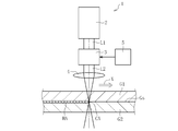
図1に示すように、本実施形態のレーザー加工方法には、レーザー加工装置1が用いられる。レーザー加工装置1は、超短パルスレーザー光L1を高繰り返し出力するレーザー光源2と、レーザー光源2から出力された超短パルスレーザー光L1を強度変調する強度変調器としての音響光学素子3と、強度変調された超短パルスレーザー光L2を集光するためのレンズ4とを備えている。
レーザー光源2は、一定のピーク強度を有する超短パルスレーザー光L1を繰り返し出力する。超短パルスレーザー光L1は、ピーク強度が一定の複数のパルスPaを含むパルス列P1から構成される。この実施形態では、超短パルスレーザー光L1は、1×10⁻⁹秒以下のパルス幅を有するものを意味する。超短パルスレーザー光L1のパルス幅は、フェムト秒(10-15秒)オーダーからピコ秒(10-12秒)オーダー(例えば、10ピコ秒)であることが好ましい。超短パルスレーザー光L1の繰り返し周波数は、100kHz~1MHzであることが好ましく、500kHz~1MHzであることがより好ましい。
音響光学素子3は、発振器5から出力された信号に基づいて超短パルスレーザー光L1を強度変調し、超短パルスレーザー光L2を出力する。強度変調された超短パルスレーザー光L2は、ピーク強度が周期的に変化する複数のパルスPbを含むパルス列P2から構成される。この実施形態では、発振器5から出力される変調信号は、所定の周波数を有する正弦波信号である。この場合、超短パルスレーザー光L1は正弦波信号の周波数で強度変調される。超短パルスレーザー光L1を強度変調する変調信号の周波数(変調周波数)は、1kHz~50kHzであることが好ましい。超短パルスレーザー光L2の繰り返し周波数は、強度変調前の超短パルスレーザー光L1と同じである。なお、強度変調器は音響光学素子3に限定されない。例えば、電気光学効果、磁気光学効果、熱光学効果、非線型光学効果などを用いて、レーザー光源2から出力される超短パルスレーザー光を強度変調してもよいし、レーザー光源2に変調信号を直接入力してレーザー光源2から強度変調された超短パルスレーザー光を出力するようにしてもよい。
レンズ4は、強度変調された超短パルスレーザー光L2を集光し、透明部材としてのガラス板Gの内部に集光領域CAを形成する。ここで、透明部材は、使用する超短パルスレーザー光L2を透過する部材を意味する。この実施形態では、ガラス板Gの厚み方向で対向する第一主面Ga及び第二主面Gbのうち、第一主面Ga側から超短パルスレーザー光L2が入射する。なお、超短パルスレーザー光L2の入射面は特に限定されない。
上記の構成を備えたレーザー加工装置1を用いてレーザー加工方法を実施すれば、ガラス板G内部の集光領域CAにおいて非線形光吸収現象が生じ、集光領域CAが局所的に溶融する。そのため、集光領域CAをX方向に走査すると、集光領域CAに対応する位置でガラス板Gの内部に熱変性領域HAが線状に形成される。この実施形態では、熱変性領域HAをガラス板Gの切断予定線に沿って形成する。その後、熱変性領域HAに引張応力を作用させるために、熱変性領域HAを加熱冷却して熱応力を生じさせたり、熱変性領域HAを中心として曲げ応力を生じさせたりするなどし、ガラス板Gを熱変性領域HAに沿って割断する。
集光領域CAにおけるスポット径は、0.5~2μmであることが好ましい。また、熱変性領域HA(又は集光領域CA)の第一主面Gaからの深さDは、20μm以上であることが好ましい。
上記のように熱変性領域を形成する際に、図2に示すように、ピーク強度が一定の超短パルスレーザー光を高繰り返しでガラス板に集光照射すると、集光領域の過度な温度上昇を原因の一つとして、図3に示すように、ガラス板の集光領域における光吸収率の時間変化が非常に大きくなるという問題がある。詳細には、光吸収率が所定時間に亘って増加し続けた後、急激に零まで減少するという光吸収率の大きな上下動を周期的に繰り返す。その結果、例えば、図4Aに示すように、ガラス板がソーダライムガラスの場合に、熱変性領域HAxの周辺にひび割れが生じるという問題が確認された。また、例えば、図4Bに示すように、ガラス板が無アルカリガラスの場合には、熱変性領域HAxに直径10μm程度のドット状の構造の乱れが周期的に生じ、熱変性領域HAxが緻密な線状にならないという問題が確認された。
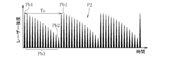
そこで、図5に示すように、本実施形態では、強度変調された超短パルスレーザー光L2を高繰り返しでガラス板Gに集光照射している。詳細には、超短パルスレーザー光L2を構成するパルス列P2は、ピーク強度の変化の周期(変調信号の周期)Ts内に、ピーク強度が最大となる最大パルスPb1と、ピーク強度が最小となる最小パルスPb2と、最大パルスPb1と最小パルスPb2との間で、最大パルスPb1側から最小パルスPb2側に向かうに連れてピーク強度が漸次減少する複数のパルスからなる中間パルス群Pb3とを含む。
この実施形態では、最大パルスPb1は、一周期Ts内の先頭と後尾に存在し、最小パルスPb2は、先頭及び後尾の最大パルスPb1間の中央(半周期に相当)に存在する。中間パルス群Pb3は、先頭の最大パルスPb1と最小パルスPb2との間、および最小パルスPb2と後尾の最大パルスPb1との間にそれぞれ存在する。
ピーク強度の変化の周期Tsは、ガラス板Gの熱拡散率に応じて適宜調整できる。例えば、ガラス板Gの熱拡散率が大きい場合には周期Tsを小さくし、ガラス板Gの熱拡散率が小さい場合には周期Tsを大きくする。周期Tsを調整する場合は、変調信号の周波数(変調周波数)を変更する。変調信号の周波数を1kHz~50kHzの範囲で変更する場合、周期Tsは0.02ms~1msの範囲で調整される。
最小パルスPb2のピーク強度は、最大パルスPb1のピーク強度の25%以上であることが好ましく、50%以上であることがより好ましい。また、最小パルスPb2のピーク強度は、最大パルスPb1のピーク強度の80%以下であることが好ましく、60%以下であることがより好ましい。
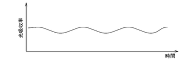
以上のようなレーザー加工方法によれば、ピーク強度が周期的に増減する超短パルスレーザー光L2がガラス板Gに集光照射される。このピーク強度の周期的な増減によって、集光領域CAの温度が過度に上昇する前にピーク強度自体が低下するため、集光領域CAの過度な温度上昇を防止することができる。その結果、図6に示すように、集光領域CAにおける光吸収率の時間変化が非常に小さくなり、光吸収率をほぼ一定に保つことができる。したがって、例えば、図7Aに示すように、ガラス板Gがソーダライムガラスの場合や、図7Bに示すように、ガラス板Gが無アルカリガラスの場合であっても、熱変性領域HAに周期的な構造の乱れが生じるのを抑制することができる。その結果、熱変性領域HAが緻密な線状になり、また熱変性領域HAやその周辺にひずみや割れも生じにくくなる。
また副次的効果ではあるが、超短パルスレーザー光L2のピーク強度を周期的に増減しながら集光照射することで、ピーク強度を一定に維持しながら集光照射する場合よりも、レーザー光源2の総出力パワーを上げることができる。これにより、ガラス板Gの集光領域CAにおける溶融量を増やすことができるので、熱変性領域HAの幅を大きくできるという利点もある。なお、ピーク強度を一定に維持しながら集光照射する場合に、レーザー光源の総出力パワーを同程度まで上げると、ガラス板に割れが生じる。
ここで、比較例である図4Aのソーダライムガラスのレーザー加工条件は、(1)光源:LD励起Nd:YAGピコ秒パルスレーザー、(2)波長:1064nm、(3)繰り返し周波数:500kHz、(4)平均出力:6W、(5)パルス幅:0.028ns、(6)スポット径:1μm、(7)スキャン速度:10mm/sである。また、比較例である図4Bの無アルカリガラスのレーザー加工条件は、(1)光源:LD励起Nd:YAGピコ秒パルスレーザー、(2)波長:1064nm、(3)繰り返し周波数:500kHz、(4)平均出力:8W、(5)パルス幅:0.028ns、(6)スポット径:1μm、(7)スキャン速度:10mm/sである。
一方、実施例である図7Aのソーダライムガラスのレーザー加工条件は、(1)光源:LD励起Nd:YAGピコ秒パルスレーザー、(2)波長:1064nm、(3)繰り返し周波数:500kHz、(4)変調周波数:2kHz、(5)平均出力(最大出力,最小出力):6W(8W,4W)、(6)パルス幅:0.028ns、(7)スポット径:1μm、(8)スキャン速度:10mm/sである。また、実施例である図7Bの無アルカリガラスのレーザー加工条件は、(1)光源:LD励起Nd:YAGピコ秒パルスレーザー、(2)波長:1064nm、(3)繰り返し周波数:500kHz、(4)変調周波数:1kHz、(5)平均出力(最大出力,最小出力):12W(16W,8W)、(6)パルス幅:0.028ns、(7)スポット径:1μm、(8)スキャン速度:10mm/sである。
なお、本発明は、上記実施形態の構成に限定されるものではなく、上記した作用効果に限定されるものでもない。本発明は、本発明の要旨を逸脱しない範囲で種々の変更が可能である。
上記の実施形態では、図5に示すように、正弦波信号を変調信号として強度変調された超短パルスレーザー光L2を得る場合を説明したが、変調信号はこれに限定されない。例えば、図8に示すように、のこぎり波信号を変調信号として強度変調された超短パルスレーザー光L2を得るようにしてもよい。この場合、超短パルスレーザー光L2を構成するパルス列P2は、例えば、変調信号の一周期Ts内の先頭及び後尾に最大パルスPb1を有し、後尾の最大パルスPb1の一つ前又はその近傍に最小パルスPb2を有する。中間パルス群Pb3は、先頭の最大パルスPb1と最小パルスPb2との間にのみ設けられる。
また、上記の実施形態では、レーザー加工として割断起点となる熱変性領域HAをガラス板Gの内部に形成する場合を説明したが、レーザー加工はこれに限定されない。例えば、レーザー加工には、接合、成形、転写などが含まれる。接合の場合を例にとって説明すると、図9に示すように、まず、透明部材として第一ガラス板G1と第二ガラス板G2を積層したものを用意する。次に、強度変調された超短パルスレーザー光L2の集光領域CAを第一及び第二ガラス板G1,G2の界面Gsに設定する。これにより、界面Gsを含む部分に熱変性領域HAを形成し、第一及び第二ガラス板G1,G2を互いに接合する。
さらに、上記の実施形態では、透明部材としてガラスを例示したが、これに限定されない。透明部材は、例えば、サファイアや水晶などの単結晶、透光性セラミックス、アクリルなどの樹脂であってもよい。
1 レーザー加工装置
2 レーザー光源
3 音響光学素子
4 レンズ
5 発振器
G ガラス板
CA 集光領域
HA 熱変性領域
L1 超短パルスレーザー光(強度変調前)
L2 超短パルスレーザー光(強度変調後)
P1 パルス列(強度変調前)
P2 パルス列(強度変調後)
Pb1 最大パルス
Pb2 最小パルス
Pb3 中間パルス群
2 レーザー光源
3 音響光学素子
4 レンズ
5 発振器
G ガラス板
CA 集光領域
HA 熱変性領域
L1 超短パルスレーザー光(強度変調前)
L2 超短パルスレーザー光(強度変調後)
P1 パルス列(強度変調前)
P2 パルス列(強度変調後)
Pb1 最大パルス
Pb2 最小パルス
Pb3 中間パルス群
Claims (7)
- 超短パルスレーザー光を集光照射し、透明部材の内部の集光領域に熱変性領域を形成するレーザー加工方法であって、
前記超短パルスレーザー光は、ピーク強度が周期的に変化するとともに、そのピーク強度の変化の一周期内に存在するパルス列が、ピーク強度が最大となる最大パルスと、ピーク強度が最小となる最小パルスと、前記最大パルスと前記最小パルスとの間で、前記最大パルス側から前記最小パルス側に向かうに連れてピーク強度が漸次減少する複数のパルスからなる中間パルス群とを含むことを特徴とするレーザー加工方法。 - 前記最小パルスのピーク強度が、前記最大パルスのピーク強度の25%以上であることを特徴とする請求項1に記載のレーザー加工方法。
- 前記超短パルスレーザー光が、1kHz~50kHzの周波数で強度変調されていることを特徴とする請求項1又は2に記載のレーザー加工方法。
- 前記超短パルスレーザー光の繰り返し周波数が、100kHz~1MHzであることを特徴とする請求項1~3のいずれか1項に記載のレーザー加工方法。
- 前記熱変性領域を前記透明部材の切断予定線に沿って線状に形成し、前記透明部材を前記熱変性領域に引張応力を作用させて割断することを特徴とする請求項1~4のいずれか1項に記載のレーザー加工方法。
- 前記透明部材が第一部材と第二部材とを含む積層体であり、前記熱変性領域を前記第一部材と前記第二部材の界面に形成し、前記第一部材と前記第二部材とを接合することを特徴とする請求項1~5のいずれか1項に記載のレーザー加工方法。
- 前記透明部材がガラスであることを特徴とする請求項1~6のいずれか1項に記載のレーザー加工方法。
Applications Claiming Priority (2)
| Application Number | Priority Date | Filing Date | Title |
|---|---|---|---|
| JP2016-206869 | 2016-10-21 | ||
| JP2016206869A JP2018065188A (ja) | 2016-10-21 | 2016-10-21 | レーザー加工方法 |
Publications (1)
| Publication Number | Publication Date |
|---|---|
| WO2018074058A1 true WO2018074058A1 (ja) | 2018-04-26 |
Family
ID=62019613
Family Applications (1)
| Application Number | Title | Priority Date | Filing Date |
|---|---|---|---|
| PCT/JP2017/030239 Ceased WO2018074058A1 (ja) | 2016-10-21 | 2017-08-24 | レーザー加工方法 |
Country Status (3)
| Country | Link |
|---|---|
| JP (1) | JP2018065188A (ja) |
| TW (1) | TW201815506A (ja) |
| WO (1) | WO2018074058A1 (ja) |
Families Citing this family (3)
| Publication number | Priority date | Publication date | Assignee | Title |
|---|---|---|---|---|
| JP2020038955A (ja) * | 2018-09-04 | 2020-03-12 | 株式会社トクヤマ | Iii族窒化物単結晶の切断方法 |
| JP2021005805A (ja) * | 2019-06-26 | 2021-01-14 | パナソニックIpマネジメント株式会社 | 光電センサ、レーザ樹脂溶着における樹脂透過率の測定方法、レーザ樹脂溶着方法、レーザ加工装置 |
| TWI904939B (zh) * | 2024-11-20 | 2025-11-11 | 台灣晶技股份有限公司 | 單晶石英材料的加工方法 |
Citations (2)
| Publication number | Priority date | Publication date | Assignee | Title |
|---|---|---|---|---|
| JP2015098042A (ja) * | 2013-11-19 | 2015-05-28 | 日本電気硝子株式会社 | 接合体の製造方法 |
| WO2015095264A2 (en) * | 2013-12-17 | 2015-06-25 | Corning Incorporated | 3-d forming of glass |
-
2016
- 2016-10-21 JP JP2016206869A patent/JP2018065188A/ja active Pending
-
2017
- 2017-08-24 WO PCT/JP2017/030239 patent/WO2018074058A1/ja not_active Ceased
- 2017-09-05 TW TW106130203A patent/TW201815506A/zh unknown
Patent Citations (2)
| Publication number | Priority date | Publication date | Assignee | Title |
|---|---|---|---|---|
| JP2015098042A (ja) * | 2013-11-19 | 2015-05-28 | 日本電気硝子株式会社 | 接合体の製造方法 |
| WO2015095264A2 (en) * | 2013-12-17 | 2015-06-25 | Corning Incorporated | 3-d forming of glass |
Also Published As
| Publication number | Publication date |
|---|---|
| JP2018065188A (ja) | 2018-04-26 |
| TW201815506A (zh) | 2018-05-01 |
Similar Documents
| Publication | Publication Date | Title |
|---|---|---|
| US8677783B2 (en) | Method for low energy separation of a glass ribbon | |
| CN101412154B (zh) | 激光加工方法 | |
| JP5967405B2 (ja) | レーザによる割断方法、及びレーザ割断装置 | |
| US20070090100A1 (en) | Glass cutting method and apparatus therefor | |
| JP2009072829A (ja) | 超短パルスレーザービームを利用した基板切断装置及びその切断方法 | |
| JP6324719B2 (ja) | ガラス基板の面取り方法及びレーザ加工装置 | |
| Chen et al. | Crack suppression of glass welding by ultrafast laser without optical contact based on light modulation | |
| KR20100119515A (ko) | 레이저 가공 방법 및 레이저 가공 장치 | |
| TWI862553B (zh) | 複合材之分斷方法 | |
| JP2018065188A (ja) | レーザー加工方法 | |
| KR101861567B1 (ko) | 레이저광에 의한 유리 기판 융착 방법 및 레이저 가공 장치 | |
| JP6141715B2 (ja) | レーザ光によるガラス基板融着方法 | |
| CN104646834A (zh) | 激光划片的方法及系统 | |
| KR102472644B1 (ko) | 취성 재료 기판의 분단 방법 그리고 분단 장치 | |
| JP2011245774A (ja) | レーザ加工方法 | |
| KR20240019081A (ko) | 복합재의 분단 방법 | |
| JP2015063417A (ja) | レーザ光によるガラス基板融着方法及びレーザ加工装置 | |
| JP2015098042A (ja) | 接合体の製造方法 | |
| KR102685458B1 (ko) | 적어도 하나의 공작물을 프로세싱하기 위한 방법 | |
| JP2015063418A (ja) | レーザ光によるガラス基板融着方法及びレーザ加工装置 | |
| US20230010132A1 (en) | Glass substrate joining method | |
| JP2009221046A (ja) | レーザー加工物 | |
| CN103466930A (zh) | 玻璃面板切割系统及其方法 | |
| JP6308733B2 (ja) | レーザ加工装置および製造方法 | |
| CN110475754A (zh) | 刻划加工方法和刻划加工装置 |
Legal Events
| Date | Code | Title | Description |
|---|---|---|---|
| 121 | Ep: the epo has been informed by wipo that ep was designated in this application |
Ref document number: 17862899 Country of ref document: EP Kind code of ref document: A1 |
|
| NENP | Non-entry into the national phase |
Ref country code: DE |
|
| 122 | Ep: pct application non-entry in european phase |
Ref document number: 17862899 Country of ref document: EP Kind code of ref document: A1 |