WO2018070133A1 - 吸収性物品 - Google Patents
吸収性物品 Download PDFInfo
- Publication number
- WO2018070133A1 WO2018070133A1 PCT/JP2017/031518 JP2017031518W WO2018070133A1 WO 2018070133 A1 WO2018070133 A1 WO 2018070133A1 JP 2017031518 W JP2017031518 W JP 2017031518W WO 2018070133 A1 WO2018070133 A1 WO 2018070133A1
- Authority
- WO
- WIPO (PCT)
- Prior art keywords
- wing
- pair
- absorbent article
- wings
- rear direction
- Prior art date
- Legal status (The legal status is an assumption and is not a legal conclusion. Google has not performed a legal analysis and makes no representation as to the accuracy of the status listed.)
- Ceased
Links
Images





Classifications
-
- A—HUMAN NECESSITIES
- A61—MEDICAL OR VETERINARY SCIENCE; HYGIENE
- A61F—FILTERS IMPLANTABLE INTO BLOOD VESSELS; PROSTHESES; DEVICES PROVIDING PATENCY TO, OR PREVENTING COLLAPSING OF, TUBULAR STRUCTURES OF THE BODY, e.g. STENTS; ORTHOPAEDIC, NURSING OR CONTRACEPTIVE DEVICES; FOMENTATION; TREATMENT OR PROTECTION OF EYES OR EARS; BANDAGES, DRESSINGS OR ABSORBENT PADS; FIRST-AID KITS
- A61F13/00—Bandages or dressings; Absorbent pads
- A61F13/15—Absorbent pads, e.g. sanitary towels, swabs or tampons for external or internal application to the body; Supporting or fastening means therefor; Tampon applicators
- A61F13/45—Absorbent pads, e.g. sanitary towels, swabs or tampons for external or internal application to the body; Supporting or fastening means therefor; Tampon applicators characterised by the shape
- A61F13/47—Sanitary towels, incontinence pads or napkins
-
- A—HUMAN NECESSITIES
- A61—MEDICAL OR VETERINARY SCIENCE; HYGIENE
- A61F—FILTERS IMPLANTABLE INTO BLOOD VESSELS; PROSTHESES; DEVICES PROVIDING PATENCY TO, OR PREVENTING COLLAPSING OF, TUBULAR STRUCTURES OF THE BODY, e.g. STENTS; ORTHOPAEDIC, NURSING OR CONTRACEPTIVE DEVICES; FOMENTATION; TREATMENT OR PROTECTION OF EYES OR EARS; BANDAGES, DRESSINGS OR ABSORBENT PADS; FIRST-AID KITS
- A61F13/00—Bandages or dressings; Absorbent pads
- A61F13/15—Absorbent pads, e.g. sanitary towels, swabs or tampons for external or internal application to the body; Supporting or fastening means therefor; Tampon applicators
- A61F13/45—Absorbent pads, e.g. sanitary towels, swabs or tampons for external or internal application to the body; Supporting or fastening means therefor; Tampon applicators characterised by the shape
- A61F13/47—Sanitary towels, incontinence pads or napkins
- A61F13/476—Sanitary towels, incontinence pads or napkins characterised by encircling the crotch region of the undergarment, e.g. with flaps
Definitions
- the present invention relates to an absorbent article in which a pair of wings overlap each other on the non-skin facing surface side of the underwear when worn.
- Patent Document 1 discloses an absorbent article in which a pair of wings overlap each other on the non-skin facing surface side of the underwear when worn.
- a pair of wings are mechanically engaged with a fastening tool such as a mechanical fastener on the non-skin facing surface side of the underwear during wearing.
- a fastening tool such as a mechanical fastener on the non-skin facing surface side of the underwear during wearing.
- Patent Document 2 discloses an absorbent article including a main body provided with an absorbent body and a pair of wings extending in the width direction from both side edges of the main body.
- the narrowest part where the length of the wing part in the longitudinal direction of the absorbent article is the smallest is located on the outer side in the width direction with respect to the root of the wing part. Accordingly, when the wing portion is folded back to the non-skin surface side of the underwear to fix the absorbent article to the underwear, the wing portion is easily bent at the narrowest portion outside the root of the wing portion.
- the absorbent article described in Patent Document 2 has an adhesive part for fixing the wing part to the clothes. This adhesive part is located outside the narrowest part of the wing part in the longitudinal direction of the absorbent article.
- the length in the longitudinal direction of the wing is gradually increased toward the inner side in the width direction. For this reason, when the wing is bent toward the non-skin surface side of the undergarment, the bending position is difficult to be defined, and the user may bend the wing at a position outside in the width direction from the design position. Therefore, it is difficult for the user to overlap the pair of wings on the non-skin facing surface side of the underwear.
- an absorbent article having a structure in which a pair of wings easily overlap on the non-skin facing surface side of the underwear is desired.
- the narrowest part of the wing part constitutes a base point for bending. Therefore, the user can easily bend the wing portion at a predetermined position.
- the inventors of the present application have discovered the following problems.
- the user When the user removes the absorbent article from the underwear, the user usually grasps one end part in the front-rear direction of the absorbent article and peels the absorbent article from the underwear in the front-rear direction from the one end part of the absorbent article. Therefore, when the absorbent article is peeled from the underwear as described above, the base of the wing part receives a force toward the downstream side in the peeling direction by being pulled by the main body part of the absorbent article.
- the adhesive part for fixing the wing part to the clothes is located outside the narrowest part of the wing part in the longitudinal direction of the absorbent article.
- the area of the adhesive portion of the wing portion is firmly fixed on the non-skin surface side of the underwear, on the outer side in the front-rear direction, that is, on the upstream side in the peeling direction with respect to the narrowest portion. Accordingly, a shearing force, that is, a force in the direction of tearing the wing portion, is applied to the narrowest portion located between the root of the wing portion and the adhesive portion.
- the liquid absorbed by the absorber near the base of the wing may leak or scatter.
- an absorbent article having a structure in which a pair of wings are easily folded at predetermined positions and having a wing portion that is difficult to break at an unintended position is desired.
- An absorbent article includes a front-rear direction, a width direction orthogonal to the front-rear direction, a main body having an absorbent body, a pair of wings extending outward in the width direction from the main body, and the pair of A wing joint provided on the wing.
- the base end portions of the pair of wings have a pair of recesses that are recessed toward the center in the front-rear direction of the wing at the front edge and the rear edge.
- the pair of wings overlap each other when the pair of wings are folded back with reference to a line that passes through the pair of recesses.
- An edge of at least one first side in the front-rear direction of the wing joint is positioned closer to the center side of the wing in the front-rear direction than the recess located on the first side.
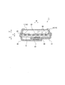
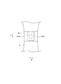
- FIG. 2 is a cross-sectional view of the absorbent article in a first wearing state with reference to the line AA in FIG. 1. It is the top view seen from the non-skin opposing surface side of the 2nd mounting state which mounted
- FIG. 3 is a cross-sectional view of the absorbent article in a second wearing state with reference to the line AA in FIG. It is a figure for demonstrating the measuring method of tear strength.
- FIG. 10 is a cross-sectional view of the absorbent article in the first wearing state with reference to the line AA in FIG. 9.
- FIG. 10 is a cross-sectional view of the absorbent article in the second wearing state with reference to the line AA in FIG. 9.
- An absorbent article includes a front-rear direction, a width direction orthogonal to the front-rear direction, a main body having an absorbent body, a pair of wings extending outward in the width direction from the main body, and the pair of A wing joint provided on the wing, wherein the base end portions of the pair of wings are recessed toward the front-rear direction center of the wing at a front edge and a rear edge.
- a pair of recesses and when the pair of wings are folded back with reference to a line extending between the pair of recesses, the pair of wings overlap each other, and at least one of the wing joints in the front-rear direction
- the edge part of the 1st side of this is located in the center side of the said front-back direction of the said wing rather than the said recessed part located in the said 1st side.
- the base end portions of the pair of wings have a pair of recesses that are recessed toward the center in the front-rear direction of the wings at the front and rear edges. Therefore, the pair of wings can be easily bent as designed with a line connecting the pair of recesses as a base point. Since the pair of wings is easily folded back to the non-skin side of the underwear at the designed position, the user can reliably overlap the pair of wings on the non-skin side of the underwear. Thereby, an absorbent article can be firmly attached to underwear.
- the user when removing the absorbent article from the underwear, the user usually grabs one end of the absorbent article in the front-rear direction and pulls the absorbent article from the underwear in the front-rear direction from the one end of the absorbent article. Accordingly, the base of the wing receives a force toward the downstream side in the peeling direction when the absorbent article is peeled off from the underwear.
- the edge part of the at least one 1st side of the front-back direction of a wing junction part is the center of the front-back direction of a wing rather than the recessed part located in a 1st side. Located on the side.
- the pair of wings is fixed on the non-skin surface side of the underwear on the downstream side in the peeling direction from the recessed portion, and more than the recessed portion.
- the upstream side in the peeling direction is not fixed. Therefore, it is difficult to apply a shearing force to the recess of the wing, and the wing can be prevented from unintentionally breaking from the recess. Thereby, it is possible to prevent leakage and scattering of liquid due to unintended breakage of the wing.
- the absorbent article according to this aspect has a structure in which a pair of wings are easily folded at predetermined positions, and has a wing that is difficult to break at an unintended position.
- At least a first wing of the pair of wings has a tear guiding portion extending in the front-rear direction from an end portion on the first side of the first wing, and the tear guiding portion. Is located outside the pair of recesses of the first wing in the width direction.
- the absorbent article When the absorbent article is peeled off from the first side, at least the first wing is easily broken at the tear guiding portion.
- the force applied to the recess is weakened, and thus it is possible to further suppress the pair of wings from being unintentionally broken from the recess.
- the tear guiding portion is located outside the pair of recesses, even if the first wing breaks at the tear guiding portion, leakage or scattering of the liquid absorbed by the absorbent body hardly occurs.
- the tear strength in the front-rear direction of the first wing at the position of the recess is higher than the tear strength in the front-rear direction of the first wing at the position of the tear guide portion.
- At least a part of the wing joint portion of the first wing is located outside the tear guiding portion in the width direction, and the pair of the pair of the wing joints is based on a line connecting the pair of recesses.
- the wing joint portion of the first wing overlaps the other second wing of the pair of wings.
- the first wing is joined to the second wing on the non-skin surface side of the underwear. Further, at least a part of the wing joint portion of the first wing is located outside the tear guiding portion in the width direction. Therefore, when the first wing is broken at the tear guide portion, the separated first wing is fixed to the second wing by the wing joint portion. Thereby, it can prevent that a 1st wing falls from an absorbent article, and the operation
- the wing joint portion of the other second wing of the pair of wings is the first wing.
- the first wing in the width direction rather than the tear guiding portion.
- the tear guiding portion is located outside the portion where the first wing and the second wing are joined to each other. Therefore, when the first wing is broken at the tear guide portion, the separated first wing is fixed to the second wing by the wing joint portion. Thereby, it can prevent that a 1st wing falls from an absorbent article, and the operation
- a part of the wing joint portion of the first wing is located inside the tear guide portion in the width direction.
- the first wing may be unintentionally broken before the absorbent article is used. In this case, the user may give up using the absorbent article.
- a part of the wing joint located inside the tear guiding portion can be fixed to the underwear. Therefore, even if the first wing breaks unintentionally before using the absorbent article, the user can use the absorbent article.
- At least one of the pair of wings has a rigid element around the recess.
- the rigidity of the region around the recess is enhanced by the rigid element, the force applied to the region around the recess when removing the absorbent article can be released outside the region around the recess. Thereby, it can suppress more that a wing will fracture
- the rigid element is constituted by an emboss applied to the wing.
- a rigid element can be easily comprised, without providing an additional member.
- the area ratio of the emboss applied to the periphery of the recess is the area ratio of the emboss applied to the outer side of the recess in the width direction and to the end of the wing in the front-rear direction. Higher than.
- the edges on both sides in the front-rear direction of the wing joint are positioned closer to the center of the wing in the front-rear direction than the pair of recesses.
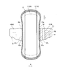
- FIG. 1 is a developed plan view of the absorbent article 1 according to the first embodiment.
- the developed plan view shown in FIG. 1 is a diagram of a developed state in which the wing of the absorbent article is developed (not folded).
- an arbitrary absorbent article such as a panty liner (orimono sheet), a sanitary napkin or an incontinence pad is assumed.
- a sanitary napkin is used as the absorbent article 1 will be described.
- the sanitary napkin of the present embodiment is a daytime sanitary napkin, but may be a night sanitary napkin.
- the absorbent article 1 has a front-rear direction L, a width direction W orthogonal to the front-rear direction L, and a thickness direction T.
- the thickness direction T has a skin facing surface side (skin surface side) T1 and a non-skin facing surface side (non-skin surface side) T2 which is the opposite side.
- the front-rear direction is a direction along the longitudinal direction of the absorbent article.
- the width direction corresponds to a direction along a line connecting the centers of the pair of wings in the front-rear direction.
- the absorbent article 1 includes an absorbent body 30, a skin surface sheet 10 positioned on the skin facing surface side with respect to the absorbent body 30, and a non-skin surface sheet 20 positioned on the non-skin facing surface side with respect to the absorbent body 30. At least.
- the skin sheet 10 has a top sheet 11 and a side sheet 12.
- the top sheet 11 covers the skin facing surface side of the absorbent body 30.
- the side sheet 12 covers the outer edge of the top sheet 11 and extends outward in the width direction from the top sheet 11.
- the skin sheet 10 can use what is normally used for an absorptive article, for example, can use the sheet
- Nonwoven fabric and paper can be used for the sheet material containing fibers.
- the non-skin surface sheet 20 is a liquid-impermeable sheet.
- the non-skin surface sheet 20 covers at least the non-skin facing surface side of the absorber 30.
- the non-skin surface sheet 20 can use what is normally used for an absorbent article, for example, a non-breathable or breathable film, a nonwoven fabric, etc. can be used.
- the absorber 30 has an absorbent core having an absorbent material such as pulp and SAP, and a core wrap that covers the absorbent core.
- an absorbent core having an absorbent material such as pulp and SAP
- a core wrap that covers the absorbent core.
- the absorbent body those normally used for absorbent articles can be used.
- the absorbent core can use hydrophilic fibers, high-molecular water-absorbing polymers, or combinations thereof, and the core wrap can be made of tissue.
- a nonwoven fabric can be used.
- the absorbent article 1 has a main body 2 and a wing 4.
- the main body 2 is located in the center in the width direction W of the absorbent article 1 and extends in the front-rear direction L.
- the wing 4 extends outward in the width direction W from the main body 2.
- the wing 4 is defined by a region extending between the base end portions 41BE and 42BE of the wings adjacent to each other in the front-rear direction and outside the base end portions 41BE and 42BE of the wing in the width direction W. .
- the base end portions 41BE and 42BE of the wing are portions located on the innermost side in the width direction of the wing and are portions intersecting with the main body portion 2.
- the main body 2 is located in the center in the width direction W of the absorbent article 1 and extends in the front-rear direction L.
- the wing 4 extends outward in the width direction W from the outer edge 2E of the main body 2.
- the main body 2 includes a top sheet 11, a side sheet 12, a non-skin surface sheet 20, and an absorber 30.
- the wing 4 includes a side sheet 12 and a non-skin surface sheet 20.
- the center 4LC in the front-rear direction of the wing 4 is located within the range in the front-rear direction of the excretion opening facing area that is disposed to face the excretion opening of the wearer.
- the wing 4 is configured to be able to be folded back to the non-skin surface sheet 20 side, and is folded to the non-skin facing surface side of the underwear when worn. The configuration of the wing 4 will be described in detail later.
- the non-skin facing surface of the non-skin sheet 20 is provided with a joint for stopping the absorbent article on the underwear S.
- the joint portion includes a main body joint portion disposed in the main body portion 2 and wing joint portions 61 and 62 disposed in the wing 4. These joints may be constituted by an adhesive, or may be configured to function as a hook and a loop of a locking system.
- the wing 4 includes a first wing 41 and a second wing 42.
- a first wing joint 61 is provided on the underwear side of the first wing 41.
- a second wing joint 62 is provided on the underwear side of the second wing 42.
- the base end of the first wing 41 has a pair of recesses 41a and 41b that are recessed toward the center in the front-rear direction L of the first wing 41 at the front and rear edges.
- the base end portion of the second wing 42 has a pair of recesses 42 a and 42 b that are recessed toward the center in the front-rear direction L of the second wing 42 at the front side edge and the rear side edge.
- the pair of wings 41 and 42 When the pair of wings 41 and 42 are folded back with reference to the lines 41L and 42L connecting the pair of recesses 41a, 41b, 42a and 42b, the pair of wings 41 and 42 overlap each other. That is, the first wing 41 and the second wing 42 overlap each other in a state where the absorbent article 1 is attached to the underwear.
- the pair of recesses 41a, 41b, 42a, 42b makes it easy for the pair of wings 41, 42 to bend as designed based on lines (virtual lines) 41L, 42L connecting the pair of recesses. Since the pair of wings 41 and 42 are easily folded back to the non-skin surface side of the underwear at the position as designed, the user can securely connect the pair of wings 41 and 42 on the non-skin side of the underwear S as will be described later. Can overlap each other. Thereby, the absorbent article 1 can be firmly attached to the underwear.
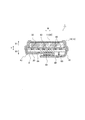
- 2 and 3 show a first wearing state in which the absorbent article is put on the underwear.
- 2 and 3 show a first wearing state in which the first wing 41 is disposed inside the second wing 42 in the thickness direction T and the absorbent article 1 is attached to the underwear S.
- 4 and 5 show a second wearing state in which the first wing 41 is disposed outside the second wing 42 in the thickness direction T, and the absorbent article 1 is worn on the underwear.
- the edge of at least one first side in the front-rear direction L of the wing joints 61, 62 is located closer to the center in the front-rear direction of the wings 41, 42 than the recess located on the first side. .
- the user when the user removes the absorbent article from the underwear, the user usually grasps one end part of the absorbent article in the front-rear direction, and peels the absorbent article from the underwear in the front-rear direction from the one end part of the absorbent article. . Therefore, the base end portion (root) of the wing receives a force toward the downstream side in the peeling direction when the absorbent article is peeled off from the underwear.
- the edge part of the at least one 1st side of the front-back direction L of the wing junction parts 61 and 62 is a wing rather than the recessed part located in a 1st side. Located on the center side in the front-rear direction.
- the pair of wings is fixed on the non-skin surface side of the underwear on the downstream side in the peeling direction from the recessed portion, and more than the recessed portion.
- the upstream side in the peeling direction is not fixed. Therefore, it is difficult to apply a shearing force to the recess of the wing, and the wing can be prevented from unintentionally breaking from the recess. Thereby, it is possible to prevent leakage and scattering of liquid due to unintended breakage of the wing.
- the absorbent article according to this aspect has a structure in which a pair of wings are easily folded at predetermined positions, and has a wing that is difficult to break at an unintended position.
- the edge portions on both sides in the front-rear direction of the wing joint portions 61, 62 are located closer to the center side in the front-rear direction L of the wings 41, 42 than the pair of recesses 41a, 41b, 42a, 42b.
- the length in the width direction of the first wing 41 (the length from the virtual line 41L to the outer edge of the first wing 41)
- the length in the width direction of the second wing 42 (the length from the imaginary line 42L to the outer edge of the second wing 42) is longer than the distance between the imaginary line 41L and the imaginary line 42L. What is necessary is just to be 1.2 times or more of the distance of virtual line 41L and virtual line 42L.
- a tear guiding portion 80 extending in the front-rear direction L from the end of the first wing 41 on the first side.
- the tear guiding portion 80 is located outside the pair of recesses 41 a and 42 b of the first wing 41 in the width direction W.
- the second wing 42 does not have a tear guiding portion. That is, the tear guiding portion 80 is provided only in the first wing 41. Instead, the second wing 42 may have a tear guiding portion.
- the tear guiding portion 80 is configured so that the wearer can easily tear the wing.
- the perforation has an opening penetrating the side sheet and the non-skin surface sheet constituting the wing.
- the weakened part is a part where the basis weight is reduced by widening the material constituting the first wing, the opening is provided in the skin sheet without providing the opening in the non-skin sheet, and the strength is compared with the surroundings.
- fever and the pressure by methods, such as the lowered part and embossing, can be illustrated.
- the tear guiding portion 80 extends in the front-rear direction L, and the tearing portion that is torn through the tear guiding portion 80 extends in the front-rear direction L.
- the front end edge of the tear guiding portion 80 may coincide with the front end edge of the first wing 41.
- the configuration is the same as the configuration in which the front end edge of the tear guiding portion 80 and the front end edge of the first wing 41 coincide.
- the first wing 41 can be easily separated through the tear guiding portion 80.
- the rear edge of the tear guide 80 may be located behind the center 4LC in the front-rear direction of the wing 4, and preferably reaches the vicinity of the rear side edge of the wing 4 in the front-rear direction. Due to the breakage of the tear guiding portion 80, the length of more than half of the length of the first wing 41 in the front-rear direction is torn. When the wearer further pulls the main body 2, the entire area in the front-rear direction of the first wing 41 can be easily divided as described later.
- the first wing 41 is easily broken at the tear guiding portion 80.
- the force applied to the recesses 41a, 41b, 42a, 42b is weakened, so that the pair of wings 41, 42 are not intended from the recesses 41a, 41b, 42a, 42b. It can suppress more that it fractures.
- the tear guiding portion 80 is located outside the pair of recesses 41a and 41b, even if the first wing 41 breaks at the tear guiding portion 80, the leakage or scattering of the liquid absorbed by the absorber 30 is not caused. Not likely to occur.
- the first wing joint 61 is located outside the tear guide 80 in the width direction W. Furthermore, the 1st wing junction part 61 is provided in the position which overlaps with the 2nd wing 42 in the state by which the pair of wings 41 and 42 were folded by the virtual lines 41L and 42L at the non-skin opposing surface side.
- the second wing joint portion 62 is provided at a position overlapping the first wing 41 in a state where the pair of wings 41 and 42 are folded to the non-skin facing surface side along the virtual lines 41L and 42L.
- the first wing 41 is joined to the second wing 42 on the non-skin surface side of the underwear. Further, at least a part of the wing joint portion 61 of the first wing 41 is located outside the tear guiding portion 80 in the width direction. Therefore, when the first wing 41 is broken at the tear guiding portion 80, the separated first wing 41 is fixed to the second wing 42 by the wing joint portion 61. Thereby, it can prevent that the 1st wing 41 falls from the absorbent article 1, and the operation
- the wing joint 62 of the second wing 42 of the pair of wings 41, 42 is provided. Is preferably overlapped with the leading end side of the first wing 41 in the width direction rather than the tear guiding portion 80 of the first wing 41.
- the tear guiding portion 80 is positioned outside the portion where the first wing 41 and the second wing 42 are joined to each other. Therefore, when the first wing 41 is broken at the tear guiding portion 80, the separated first wing 41 is fixed to the second wing 42 by the wing joint portion. Thereby, it can prevent that the 1st wing 41 falls from an absorbent article, and the operation
- the tear guiding portion 80 is disposed on the inner side in the width direction than the first wing joint portion 61 in the unfolded state of the first wing 41 shown in FIGS. 1 and 2.
- the distance between the first wing joint 61 and the tear guide 80 may be shorter than the distance between the virtual line 41L that connects the pair of recesses of the first wing 41 and the tear guide 80.
- the tear strength in the front-rear direction L of the first wing 41 at the positions of the recesses 41 a and 41 b is preferably higher than the tear strength in the front-rear direction of the first wing 41 at the position of the tear guiding portion 80.
- the first wing 41 is more likely to break at the tear guiding portion 80. Therefore, when the absorbent article is peeled from the underwear, the first wing 41 can be surely easily broken at the tear guiding portion 80.
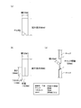
- FIG. 6 is a diagram for explaining a tear strength measurement method.
- FIGS. 6A and 6B are diagrams showing a measurement specimen for measuring the tear strength of the wing.
- FIG. 6C shows a measurement method.
- the length of the measurement specimen is 60 mm, and the width of the measurement specimen is 25 mm.
- the test piece shown in FIG. 6A has the same shape and the same size as the recesses 41a and 41b of the first wing. Recesses 41a and 41b are provided.
- the test piece shown in FIG. 6B has a perforation corresponding to the tear guiding portion 80 with a length of 30 mm. ing.
- the test piece shown in FIGS. 6A and 6B is attached to a tensile tester so that the chucking distance is 10 mm with respect to each chuck.
- the test piece is pulled at a pulling speed of 300 mm / min, the maximum load until breakage is determined, and the value is taken as the tear strength.
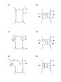
- FIG. 7 is a diagram schematically showing the removal mode in the second mounting state.
- the main body 2 is joined to the skin facing surface side of the underwear S, and the pair of wings 4 are It is joined to the non-skin facing side of the underwear. More specifically, in the first wearing state, the first wing 41 and the undergarment S are joined via the first wing joint 61, and the first wing 41 and the second wing 42 are joined via the second wing joint 62. And are joined. In the second mounting state, the second wing 42 and the undergarment S are joined via the second wing joint 62, and the first wing 41 and the second wing 42 are joined via the first wing joint 61. Has been.
- the wearer When removing the absorbent article 1, the wearer generally holds the front end edge of the main body 2 and pulls the front end edge of the main body 2 away from the undergarment (FIG. 7C). Since the pair of wings 4 are bonded to each other on the non-skin facing surface side of the underwear, when the main body 2 is separated from the underwear, the pair of wings 4 is to be maintained while being bonded to the underwear, and is torn between the main body 2 and the wing 4. It takes power. The force applied to the wing 4 tends to act strongly on the front side gripped by the wearer.
- the pair of wings are fixed by the joint portions 61 and 62 on the non-skin surface side of the underwear on the downstream side in the peeling direction from the recessed portion, and are pulled more than the recessed portion.
- the upstream side in the peeling direction is not fixed. Thereby, it is difficult to apply a shearing force to the recess, and the wing is difficult to break from the recess.
- the force applied to the tear guiding portion 80 increases, and the first wing 41 is torn through the tear guiding portion 80 (see FIG. 7D).
- the first wing 41 is separated into two along the front-rear direction L as shown in FIGS. 7E and 7F.
- first wing 41 When the first wing 41 is separated into two in the first mounted state, one first wing (base end side of the wing) is connected to the main body portion 2 and the other first wing (outer edge side in the deployed state of the wing). ) Continues to the second wing 42 via the second wing joint 62. When the wearer further pulls the absorbent article, the first wing joint 61 and the undergarment are separated, and the main body joint 60 and the undergarment are separated, and the entire absorbent article is removed from the undergarment.
- first wing 41 when the first wing 41 is separated into two in the second mounted state, one first wing (base end side of the wing) is connected to the main body 2 and the other first wing (in the deployed state of the wing). The outer edge side) continues to the second wing 42 via the first wing joint 61.
- the wearer further pulls the absorbent article, the second wing joint 62 and the undergarment are separated, and the main body joint 60 and the undergarment are separated, and the entire absorbent article is removed from the undergarment.
- FIG. 8 is a developed plan view of the absorbent article according to the second embodiment.
- the base end portion of the first wing 41 has a pair of recesses 41 a and 41 b that are recessed toward the center in the front-rear direction L of the first wing 41 at the front edge and the rear edge.
- the base end portion of the second wing 42 has a pair of recesses 42 a and 42 b that are recessed toward the center in the front-rear direction L of the second wing 42 at the front side edge and the rear side edge.
- the pair of wings 41 and 42 When the pair of wings 41 and 42 are folded back with reference to the lines 41L and 42L connecting the pair of recesses 41a, 41b, 42a and 42b, the pair of wings 41 and 42 overlap each other. That is, the first wing 41 and the second wing 42 overlap each other in a state where the absorbent article 1 is attached to the underwear.
- the front edge in the front-rear direction L of the wing joints 61, 62 is located on the center side in the front-rear direction of the wings 41, 42, that is, on the rear side relative to the recesses 41a, 42a located on the front side.
- the user when removing the absorbent article from the underwear, the user often grasps the front side of the absorbent article and pulls the absorbent article from the underwear in the front-rear direction from the front side of the absorbent article. Therefore, the base end portion (root) of the wing receives a force toward the downstream side (that is, the rear side) in the peeling direction when the absorbent article is peeled from the underwear.
- the edge part of the front side of the wing junction parts 61 and 62 is located in the back side of the wings 41 and 42 rather than the recessed part 41a and 42a located in the front side.
- the pair of wings 41 and 42 are fixed on the non-skin surface side of the underwear on the downstream side in the peeling direction from the recesses 41a and 42a.
- the upstream side in the peeling direction is not fixed from the recesses 41a and 42a. Therefore, it is difficult to apply a shearing force to the recesses 41a and 42a of the wing, and the wing can be prevented from unintentionally breaking from the recesses 41a and 42a. Thereby, it is possible to prevent liquid leakage and scattering due to unintended breakage of the wings 41 and 42.
- the tear guiding portion 80 can be configured from a portion whose strength is lower than the surroundings.
- the first wing 41 includes a sheet joining region R1 in which the skin sheet 10 and the non-skin sheet 20 are joined, and a sheet non-joint in which the skin sheet 10 and the non-skin sheet 20 are not joined. And a junction region R2.
- the sheet joining region R1 and the sheet non-joining region R2 extend in the front-rear direction.
- the sheet bonding region R1 is a region that is hatched in FIG.
- the sheet joining region R1 is a region where the sheets are joined by an adhesive such as HMA, heat welding, or the like.
- the tear guiding portion 80 is configured by the non-joining region R2.
- the tear guiding portion 80 may include a recess 81 that is recessed backward from the front end edge of the first wing 41. In this case, the tear guiding portion 80 can be easily torn from the recess 81.
- various tear induction portions exemplified in the first embodiment can be applied.
- FIG. 9 is a developed plan view of the absorbent article according to the third embodiment.
- FIG. 10 shows a first wearing state in which the absorbent article is put on the underwear.
- the first wing 41 is disposed inside the second wing 42 in the thickness direction T, and the absorbent article 1 is attached to the undergarment S.
- FIG. 11 shows a second wearing state in which the absorbent article is put on the underwear.
- the 1st wing 41 is arrange
- the first wing joint 61 includes a first outer wing joint 61a and a first inner wing joint 61b.
- the first outer wing joint portion 61a is provided outside the tear guiding portion 80 in the width direction.
- the first inner wing joint 61b is provided on the inner side of the tear guide 80 in the width direction.
- the second wing joint 62 includes a second outer wing joint 62a and a second inner wing joint 62b.
- the second outer wing joint 62a is provided outside the second inner wing joint 62b in the width direction.
- At least one first side edge in the front-rear direction L of the wing joints 61a, 61b, 62a, 62b is winged more than the concave portion located on the first side.
- 41 and 42 are located on the center side in the front-rear direction.
- the edge part of the both sides of the front-back direction of the wing junction part 61a, 61b, 62a, 62b is the center side of the front-back direction L of the wings 41 and 42 rather than a pair of recessed part 41a, 41b, 42a, 42b.
- the first wing joint portion 61 is located outside the tear guiding portion 80 in the width direction W.
- the 1st outer side wing junction part 61a is provided in the position which overlaps with the 2nd wing 42 in the state by which the pair of wings 41 and 42 were folded by the virtual lines 41L and 42L at the non-skin opposing surface side.
- the second outer wing joint portion 62a is provided at a position overlapping the first wing 41 in a state where the pair of wings 41, 42 are folded to the non-skin facing surface side along the virtual lines 41L, 42L.
- the first wing 41 is joined to the second wing 42 by the first outer wing joining portion 61a on the non-skin surface side of the underwear.
- the 1st outer side wing junction part 61a is located in the outer side rather than the tear induction
- the second outer wing joint 62a It is preferable to overlap with the tip side of the first wing 41 in the width direction.
- the tear guiding portion 80 is located outside the portion where the first wing 41 and the second wing 42 are joined to each other. Therefore, when the first wing 41 is broken at the tear guiding portion 80, the separated first wing 41 is fixed to the second wing 42 by the second outer wing joint portion 62a. Thereby, it can prevent that the 1st wing 41 falls from an absorbent article, and the operation
- a part of the first wing joint portion that is, the first inner wing joint portion 61b is located inside the tear guiding portion 80 in the width direction W.
- the first wing 41 may be broken unintentionally before the absorbent article is used. In this case, the user may give up using the absorbent article.
- the first inner wing joint 61b positioned on the inner side of the tear guiding portion 80 can be fixed to the undergarment. Therefore, even if the first wing 41 breaks unintentionally before using the absorbent article, the user can use the absorbent article.
- the rigid element 88 is configured by embossing applied to the wings 41 and 42.
- the rigid element 88 need not be configured by embossing as long as the rigidity around the recesses 41a, 41b, 42a, and 42a can be increased.
- the rigid element 88 may be composed of an additional sheet member provided around the recesses 41a, 41b, 42a, 42a.
- the rigidity of the regions around the recesses 41a, 41b, 42a, and 42a is increased by the rigid element 88, the force applied to the regions around the recesses 41a, 41b, 42a, and 42a when removing the absorbent article is reduced. It can escape to the outer side rather than the area
- the rigid element 88 is preferably configured by embossing applied to the wings 41 and 42. In this case, the rigid element 88 can be easily configured without providing an additional member.
- the area ratio of the embosses (rigid elements) provided around the recesses 41a, 41b, 42a, 42a is outside the recesses 41a, 41b, 42a, 42a in the width direction W and in the front-rear direction of the wings 41, 42. It is higher than the area ratio of the emboss 89 applied to the end.
- the rigidity of the regions around the recesses 41a, 41b, 42a, 42a can be relatively increased. Therefore, when removing the absorbent article, the force applied to the area around the recesses 41a, 41b, 42a, 42a can be released outside the area around the recesses 41a, 41b, 42a, 42a, and the wings are recessed. From this, it is possible to further suppress unintentional breakage.
- an absorbent article having a structure in which a pair of wings are easily overlapped with each other on the non-skin facing surface side of the underwear and having a wing portion that is difficult to break at an unintended position.
Landscapes
- Health & Medical Sciences (AREA)
- Epidemiology (AREA)
- Engineering & Computer Science (AREA)
- Biomedical Technology (AREA)
- Heart & Thoracic Surgery (AREA)
- Vascular Medicine (AREA)
- Life Sciences & Earth Sciences (AREA)
- Animal Behavior & Ethology (AREA)
- General Health & Medical Sciences (AREA)
- Public Health (AREA)
- Veterinary Medicine (AREA)
- Absorbent Articles And Supports Therefor (AREA)
Abstract
一対のウイング同士が所定の位置で折られ易い構造を有しつつ、意図しない位置で破断し難いウイング部を有する吸収性物品を提供する。吸収性物品(1)は、前後方向(L)と、前後方向に直交する幅方向(W)と、吸収体(30)を有する本体部(2)と、本体部から幅方向外側に延出する一対のウイング(41,42)と、一対のウイングに設けられたウイング接合部(61,62)と、を備える。一対のウイングの基端部は、前側縁及び後側縁において、ウイングの前後方向の中心へ向かって凹む一対の凹部(41a,41b,42a,42b)を有する。一対の凹部をむすぶライン(41L,42L)を基準として一対のウイングを折り返したときに、一対のウイングどうしが互いに重なり合う。ウイング接合部(61,62)の、前後方向のうちの少なくとも一方の第1の側の縁部は、当該第1の側に位置する凹部よりもウイングの前後方向の中心側に位置する。
Description
本発明は、装着時に下着の非肌対向面側で一対のウイング同士が重なり合う吸収性物品に関する。
特許文献1は、装着時に下着の非肌対向面側で一対のウイング同士が重なり合う吸収性物品を開示している。特許文献1では、装着時に下着の非肌対向面側で、一対のウイング同士がメカニカルファスナーのような締結用具で機械的に係合される。これにより、下着に吸収性物品が固定される。この吸収性物品のウイングの長手方向の長さは、幅方向の内側に向かうにつれて徐々に長くなっている。
特許文献2は、吸収体を備える本体部と、本体部の両側縁から幅方向に延出する一対のウイング部とを含む吸収性物品を開示している。吸収性物品の長手方向におけるウイング部の長さが最も小さい最狭部は、ウイング部の付け根に対して幅方向外側に位置する。これにより、吸収性物品を下着に固定するためにウイング部を下着の非肌面側へ折り返すとき、ウイング部は、ウイング部の付け根よりも外側の最狭部で折り曲がり易くなる。
また、特許文献2に記載された吸収性物品は、ウイング部を着衣に固定するための粘着部を有する。この粘着部は、吸収性物品の長手方向において、ウイング部の最狭部よりも外側に位置する。
特許文献1に記載の吸収性物品では、ウイングの長手方向の長さが、幅方向の内側に向かうにつれて徐々に長くなっている。そのため、ウイングを下着の非肌面側に折り曲げるときに、折り曲げ位置が規定され難く、使用者は、設計上の位置よりも幅方向外側の位置で、ウイングを折り曲げてしまうことがある。したがって、使用者は、一対のウイング同士を下着の非肌対向面側で重なり合わせることが困難である。
したがって、一対のウイング同士が下着の非肌対向面側で重なり易い構造を有する吸収性物品が望まれる。
ここで、特許文献2に記載の吸収性物品では、ウイング部の最狭部が折れ曲がるための基点を構成する。したがって、使用者はウイング部を規定の位置で折り曲げ易い。しかしながら、本願の発明者は、以下のような課題を発見した。
使用者は、吸収性物品を下着から取り外す際に、通常、吸収性物品の前後方向の一端部を掴み、吸収性物品の当該一端部から前後方向に吸収性物品を下着から引きはがす。したがって、ウイング部の根元は、前述したように吸収性物品を下着から剥がす際に、吸収性物品の本体部に引っ張られることによって、引きはがし方向の下流側へ向かう力を受ける。ここで、特許文献2に記載の吸収性物品では、ウイング部を着衣に固定するための粘着部が、吸収性物品の長手方向において、ウイング部の最狭部よりも外側に位置する。したがって、ウイング部の粘着部の領域は、下着の非肌面側において、最狭部よりも前後方向の外側、すなわち引きはがし方向の上流側でしっかり固定されている。したがって、ウイング部の根元と粘着部との間に位置する最狭部に、せん断力、すなわちウイング部を引き裂く方向の力が印加される。
特に、特許文献1に記載されたように一対のウイング部が下着の非肌面側で互いに固定される場合、一対のウイング部は、直接下着に固定されるよりも強固に固定され易い。そのため、吸収性物品を下着から剥がす際に、ウイング部の根元と粘着部との間に位置する最狭部に、より強いせん断力が印加され易い。
ウイング部が、ウイング部の根元付近の最狭部で不意に引き裂かれると、ウイングの根元付近の吸収体に吸収された液体が漏れたり、飛び散ったりすることがある。
したがって、一対のウイング同士が所定の位置で折られ易い構造を有しつつ、意図しない位置で破断し難いウイング部を有する吸収性物品が望まれる。
一態様に係る吸収性物品は、前後方向と、前記前後方向に直交する幅方向と、吸収体を有する本体部と、前記本体部から幅方向外側に延出する一対のウイングと、前記一対のウイングに設けられたウイング接合部と、を備える。一対のウイングの基端部は、前側縁及び後側縁において、前記ウイングの前記前後方向の中心へ向かって凹む一対の凹部を有する。前記一対の凹部をむすぶラインを基準として前記一対のウイングを折り返したときに、前記一対のウイングどうしが互いに重なり合う。前記ウイング接合部の、前記前後方向のうちの少なくとも一方の第1の側の縁部は、前記第1の側に位置する前記凹部よりも前記ウイングの前記前後方向の中心側に位置する。
(1)実施形態の概要
本明細書及び添付図面の記載により、少なくとも以下の事項が明らかとなる。
本明細書及び添付図面の記載により、少なくとも以下の事項が明らかとなる。
一態様に係る吸収性物品は、前後方向と、前記前後方向に直交する幅方向と、吸収体を有する本体部と、前記本体部から幅方向外側に延出する一対のウイングと、前記一対のウイングに設けられたウイング接合部と、を備えた吸収性物品であって、前記一対のウイングの基端部は、前側縁及び後側縁において、前記ウイングの前記前後方向の中心へ向かって凹む一対の凹部を有し、前記一対の凹部をむすぶラインを基準として前記一対のウイングを折り返したときに、前記一対のウイングどうしが互いに重なり合い、前記ウイング接合部の、前記前後方向のうちの少なくとも一方の第1の側の縁部は、前記第1の側に位置する前記凹部よりも前記ウイングの前記前後方向の中心側に位置する。
本態様によれば、一対のウイングの基端部は、前側縁及び後側縁において、ウイングの前後方向の中心へ向かって凹む一対の凹部を有する。したがって、一対のウイングは、一対の凹部を結ぶラインを基点に設計どおりに折れやすくなる。設計どおりの位置で一対のウイングが下着の非肌面側へ折り返され易くなるので、使用者は、下着の非肌側で確実に一対のウイングどうしを互いに重なり合わせることができる。これにより、吸収性物品をしっかりと下着に取り付けることができる。
また、使用者は、吸収性物品を下着から取り外す際に、通常、吸収性物品の前後方向の一端部を掴み、吸収性物品の当該一端部から前後方向に吸収性物品を下着から引きはがす。したがって、ウイングの根元は、吸収性物品を下着から剥がす際に、引きはがし方向の下流側へ向かう力を受ける。ここで、本態様に係る吸収性物品では、ウイング接合部の、前後方向のうちの少なくとも一方の第1の側の縁部は、第1の側に位置する凹部よりもウイングの前後方向の中心側に位置する。この場合、吸収性物品が第1の側から引きはがされると、一対のウイングは、下着の非肌面側において、凹部よりも引きはがし方向の下流側で固定されており、凹部よりも引きはがし方向の上流側は固定されていないことになる。したがって、ウイングの凹部にせん断力がかかり難く、ウイングが凹部から意図せず破断してしまうことを抑制することができる。これにより、ウイングの意図しない破断に起因する液体の漏れや飛び散りを防止することができる。
以上のように、本態様に係る吸収性物品は、一対のウイング同士が所定の位置で折られ易い構造を有しつつ、意図しない位置で破断し難いウイングを有する。
好ましい一態様によれば、前記一対のウイングのうちの少なくとも第1ウイングは、前記第1ウイングの前記第1の側の端部から前記前後方向に延びる引裂誘導部を有し、前記引裂誘導部は、前記幅方向において前記第1ウイングの前記一対の凹部よりも外側に位置する。
吸収性物品が第1の側から引きはがされたとき、少なくとも第1ウイングは、引裂誘導部のところで破断し易くなっている。第1ウイングが引裂誘導部のところで破断され始めると、凹部にかかる力が弱まるので、一対のウイングが凹部から意図せず破断してしまうことをより抑制することができる。
また、引裂誘導部は一対の凹部よりも外側に位置するので、引裂誘導部のところで第1ウイングが破断したとしても、吸収体に吸収された液体の漏れや飛び散りは生じ難い。
好ましい一態様によれば、前記凹部の位置における前記第1ウイングの前記前後方向の引き裂き強度は、前記引裂誘導部の位置における前記第1ウイングの前記前後方向の引き裂き強度よりも高い。
これにより、第1ウイングは、引裂誘導部のところでより破断しやすくなっている。したがって、吸収性物品を下着からはがす際に、第1ウイングを引裂誘導部のところで確実に破断し易くすることができる。
好ましい一態様によれば、前記第1ウイングの前記ウイング接合部の少なくとも一部は、前記幅方向において前記引裂誘導部よりも外側に位置し、前記一対の凹部を結ぶラインを基点に前記一対のウイングを折った場合に、前記第1ウイングの前記ウイング接合部は、前記一対のウイングのうちの他方の第2ウイングに重なる。
これにより、少なくとも図4及び図5に示すような第2装着状態では、第1ウイングは、下着の非肌面側で第2ウイングに接合される。また、第1ウイングのウイング接合部の少なくとも一部は、幅方向において引裂誘導部よりも外側に位置している。したがって、引裂誘導部のところで第1ウイングが破断されたときに、分離した第1ウイングは、ウイング接合部によって第2ウイングに固定された状態となる。これにより、第1ウイングが吸収性物品から落下することを防ぐことができ、吸収性物品を下着から取り外す作業を清潔に行うことができる。
好ましい一態様によれば、前記一対の凹部を結ぶラインを基点に前記一対のウイングを折った場合に、前記一対のウイングのうちの他方の第2ウイングの前記ウイング接合部は、前記第1ウイングの前記引裂誘導部よりも前記幅方向における前記第1ウイングの先端側に重なる。
これにより、少なくとも図2及び図3に示すような第1装着状態では、引裂誘導部は、第1ウイングと第2ウイングとを互いに接合する部分よりも外側に位置する。したがって、引裂誘導部のところで第1ウイングが破断されたときに、分離した第1ウイングは、ウイング接合部によって第2ウイングに固定された状態となる。これにより、第1ウイングが吸収性物品から落下することを防ぐことができ、吸収性物品を下着から取り外す作業を清潔に行うことができる。
好ましい一態様によれば、前記第1ウイングの前記ウイング接合部の一部は、前記幅方向において前記引裂誘導部よりも内側に位置する。
前述したように、少なくとも第1ウイングに引裂誘導部を設けることで、第1ウイングが凹部のところで破断してしまうことを抑制することができる。しかしながら、第1ウイングが引裂誘導部のところで破断し易くなっていると、吸収性物品の使用前に、意図せず第1ウイングが破断してしまうこともあり得る。この場合、使用者は、吸収性物品の使用を断念することがある。本態様では、意図せず第1ウイングが破断してしまっても、引裂誘導部よりも内側に位置するウイング接合部の一部を下着に固定することができる。よって、吸収性物品の使用前に意図せず第1ウイングが破断してしまっても、使用者はその吸収性物品を使用することができる。
好ましい一態様によれば、前記一対のウイングの少なくとも一方は、前記凹部の周囲に剛性要素を有する。
剛性要素によって凹部の周囲の領域の剛性が高められるため、吸収性物品を取り外す際に凹部の周囲の領域にかかる力を、凹部の周囲の領域よりも外側へ逃がすことができる。これにより、ウイングが凹部から意図せず破断してしまうことをより抑制することができる。
好ましい一態様によれば、前記剛性要素は、前記ウイングに施されたエンボスによって構成される。これにより、追加の部材を設けることなく、容易に剛性要素を構成することができる。
好ましい一態様によれば、前記凹部の周囲に施された前記エンボスの面積率は、前記幅方向において前記凹部よりも外側、かつ前記ウイングの前記前後方向の端部に施されたエンボスの面積率よりも高い。
これにより、凹部の周囲に施されたエンボスの面積率を高くすることによって、凹部の周囲の領域の剛性を高めることができる。したがって、吸収性物品を取り外す際に凹部の周囲の領域にかかる力を、凹部の周囲の領域よりも外側へ逃がすことができ、ウイングが凹部から意図せず破断してしまうことをより抑制することができる。
好ましい一態様によれば、前記ウイング接合部の、前記前後方向の両側の縁部は、前記一対の凹部よりも前記ウイングの前記前後方向の中心側に位置する。
これにより、吸収性物品を前後方向のどちらから剥がした場合であっても、凹部にせん断力がかかり難くなる。したがって、吸収性物品を前後方向のどちらから剥がした場合であっても、ウイング部が凹部から意図せず破断してしまうことを抑制することができる。
(2)吸収性物品の構成
以下、図面を参照して第1実施形態に係る吸収性物品1について説明する。なお、以下の図面の記載において、同一又は類似の部分には、同一又は類似の符号を付している。ただし、図面は模式的なものであり、各寸法の比率等は現実のものとは異なることに留意すべきである。したがって、具体的な寸法等は、以下の説明を参酌して判断すべきである。また、図面相互間においても互いの寸法の関係や比率が異なる部分が含まれ得る。
以下、図面を参照して第1実施形態に係る吸収性物品1について説明する。なお、以下の図面の記載において、同一又は類似の部分には、同一又は類似の符号を付している。ただし、図面は模式的なものであり、各寸法の比率等は現実のものとは異なることに留意すべきである。したがって、具体的な寸法等は、以下の説明を参酌して判断すべきである。また、図面相互間においても互いの寸法の関係や比率が異なる部分が含まれ得る。
図1は、第1実施形態に係る吸収性物品1の展開平面図である。図1に示す展開平面図は、吸収性物品のウイングを展開した(折り返していない)展開状態の図である。吸収性物品1としては、パンティーライナー(おりものシート)や生理用ナプキンや失禁パッド等の任意の吸収性物品が想定される。本実施形態では、かかる吸収性物品1として生理用ナプキンが用いられるケースについて説明する。また、本実施の形態の生理用ナプキンは、昼用の生理用ナプキンであるが、夜用の生理用ナプキンであってもよい。
吸収性物品1は、前後方向Lと、前後方向Lに直交する幅方向Wと、厚み方向Tと、を有する。厚み方向Tは、肌対向面側(肌面側)T1及びその反対側である非肌対向面側(非肌面側)T2を有する。前後方向は、吸収性物品の長手方向に沿う方向である。幅方向は、一対のウイングの前後方向の中心同士を結ぶ線に沿う方向に相当する。
吸収性物品1は、吸収体30と、吸収体30よりも肌対向面側に位置する肌面シート10と、吸収体30よりも非肌対向面側に位置する非肌面シート20と、を少なくとも備える。
肌面シート10は、トップシート11とサイドシート12を有する。トップシート11は、吸収体30の肌対向面側を覆う。サイドシート12は、トップシート11の外側縁を覆い、トップシート11よりも幅方向外側に延出する。肌面シート10は、通常吸収性物品に使用されているものを使用することができ、例えば、繊維を含むシート材、又は開孔フィルムなどを用いることができる。繊維を含むシート材は、不織布及び紙を用いることができる。
非肌面シート20は、液不透過性のシートである。非肌面シート20は、少なくとも吸収体30の非肌対向面側を覆う。非肌面シート20は、通常吸収性物品に使用されているものを使用することができ、例えば、非通気性や通気性のフィルム、不織布等を用いることができる。
吸収体30は、パルプやSAP等の吸収材料を有する吸収コアと、吸収コアを覆うコアラップと、を有する。吸収体は、通常吸収性物品に使用されているものを使用することができ、例えば、吸収コアは、親水性繊維、高分子吸水ポリマー、またはこれらの組み合わせを用いることができ、コアラップは、ティッシュ、不織布を用いることができる。
吸収性物品1は、本体部2と、ウイング4と、を有する。本体部2は、吸収性物品1の幅方向Wの中央に位置し、前後方向Lに延びる。ウイング4は、本体部2よりも幅方向Wの外側に延出している。具体的には、ウイング4は、前後方向に隣接するウイングの基端部41BE,42BEどうしの間で、ウイングの基端部41BE,42BEよりも幅方向Wの外側に延びた領域によって規定される。
本明細書において、ウイングの基端部41BE,42BEは、ウイングの最も幅方向内側に位置する部分であり、本体部2と交差する部分である。本体部2は、吸収性物品1の幅方向Wの中央に位置し、前後方向Lに延びる。ウイング4は、本体部2の外側縁2Eよりも幅方向Wの外側に延出している。
本体部2は、トップシート11と、サイドシート12と、非肌面シート20と、吸収体30と、を含む。ウイング4は、サイドシート12と、非肌面シート20と、を有する。ウイング4の前後方向の中心4LCは、着用者の排泄口に対向して配置される排泄口対向域の前後方向の範囲内に位置する。ウイング4は、非肌面シート20側に折り返し可能に構成されており、装着時に下着の非肌対向面側に折り返される。ウイング4の構成については、後述にて詳細に説明する。
非肌面シート20の非肌対向面には、吸収性物品を下着Sに止めるための接合部が設けられている。接合部は、本体部2に配置された本体接合部と、ウイング4に配置されたウイング接合部61,62と、を有する。これらの接合部は、接着剤によって構成されていてもよいし、フックと係止システムのループとして機能するように構成されていてもよい。
(3)ウイングの構成
ウイング4は、第1ウイング41と第2ウイング42を有する。第1ウイング41の下着側に第1ウイング接合部61が設けられている。第2ウイング42の下着側に第2ウイング接合部62が設けられている。
ウイング4は、第1ウイング41と第2ウイング42を有する。第1ウイング41の下着側に第1ウイング接合部61が設けられている。第2ウイング42の下着側に第2ウイング接合部62が設けられている。
第1ウイング41の基端部は、前側縁及び後側縁において、第1ウイング41の前後方向Lの中心へ向かって凹む一対の凹部41a,41bを有する。第2ウイング42の基端部は、前側縁及び後側縁において、第2ウイング42の前後方向Lの中心へ向かって凹む一対の凹部42a,42bを有する。
一対の凹部41a,41b,42a,42bをむすぶライン41L,42Lを基準として一対のウイング41,42を折り返したときに、一対のウイング41,42どうしは互いに重なり合う。すなわち、吸収性物品1が下着に装着された状態で第1ウイング41と第2ウイング42が互いに重なりあう。
一対の凹部41a,41b,42a,42bによって、一対のウイング41,42は、一対の凹部を結ぶライン(仮想線)41L,42Lを基点に設計どおりに折れやすくなる。設計どおりの位置で一対のウイング41,42が下着の非肌面側へ折り返され易くなるので、使用者は、後述するように下着Sの非肌側で確実に一対のウイング41,42どうしを互いに重なり合わせることができる。これにより、吸収性物品1をしっかりと下着に取り付けることができる。
図2及び図3は、吸収性物品を下着に装着した第1装着状態を示す。図2及び図3では、第1ウイング41が第2ウイング42の厚み方向Tの内側に配置されて、吸収性物品1が下着Sに装着された第1装着状態を示している。図4及び図5は、第1ウイング41が第2ウイング42の厚み方向Tの外側に配置されて、吸収性物品1が下着に装着された第2装着状態を示す。
ウイング接合部61,62の、前後方向Lのうちの少なくとも一方の第1の側の縁部は、当該第1の側に位置する凹部よりもウイング41,42の前後方向の中心側に位置する。
ここで、使用者は、吸収性物品を下着から取り外す際に、通常、吸収性物品の前後方向の一端部を掴み、吸収性物品の当該一端部から前後方向に吸収性物品を下着から引きはがす。したがって、ウイングの基端部(根元)は、吸収性物品を下着から剥がす際に、引きはがし方向の下流側へ向かう力を受ける。ここで、本態様に係る吸収性物品では、ウイング接合部61,62の、前後方向Lのうちの少なくとも一方の第1の側の縁部は、第1の側に位置する凹部よりもウイングの前後方向の中心側に位置する。この場合、吸収性物品が第1の側から引きはがされると、一対のウイングは、下着の非肌面側において、凹部よりも引きはがし方向の下流側で固定されており、凹部よりも引きはがし方向の上流側は固定されていないことになる。したがって、ウイングの凹部にせん断力がかかり難く、ウイングが凹部から意図せず破断してしまうことを抑制することができる。これにより、ウイングの意図しない破断に起因する液体の漏れや飛び散りを防止することができる。
以上のように、本態様に係る吸収性物品は、一対のウイング同士が所定の位置で折られ易い構造を有しつつ、意図しない位置で破断し難いウイングを有する。
第1実施形態では、ウイング接合部61,62の、前後方向の両側の縁部が、一対の凹部41a,41b,42a,42bよりもウイング41,42の前後方向Lの中心側に位置する。これにより、吸収性物品を前後方向のどちらから剥がした場合であっても、凹部41a,41b,42a,42bにせん断力がかかり難くなる。したがって、吸収性物品1を前後方向Lのどちらから剥がした場合であっても、ウイング41,42が凹部41a,41b,42a,42bから意図せず破断してしまうことを抑制することができる。
第1ウイング41と第2ウイング42が下着に装着された状態で互いに重なり合うようにするため、第1ウイング41の幅方向の長さ(仮想線41Lから第1ウイング41の外側縁までの長さ)と第2ウイング42の幅方向の長さ(仮想線42Lから第2ウイング42の外側縁までの長さ)を合わせた合計長さは、仮想線41Lと仮想線42Lとの距離よりも長ければよく、仮想線41Lと仮想線42Lとの距離の1.2倍以上であることが好ましい。
第1ウイング41の前記第1の側の端部から前後方向Lに延びる引裂誘導部80を有することが好ましい。引裂誘導部80は、幅方向Wにおいて第1ウイング41の一対の凹部41a,42bよりも外側に位置する。
第2ウイング42は引裂誘導部を有しない。すなわち、引裂誘導部80は、第1ウイング41のみに設けられる。この代わりに、第2ウイング42が引裂誘導部を有していてもよい。
引裂誘導部80は、着用者がウイングを容易に引き裂くことができるように構成されており、具体的には、ミシン目、ウイングの前端縁から後方に向かって凹む凹部、資材の強度を周囲よりも低くした脆弱部、及びこれらの組み合わせによって構成される。ミシン目は、ウイングを構成するサイドシート及び非肌面シートを貫通した開口を有する。また、脆弱部は、第1ウイングを構成する資材を拡幅することによって目付を低下させた部分、非肌面シートに開口を設けずに肌面シートに開口を設け、周囲と比較して強度を低くした部分、エンボス等の方法によって熱及び圧力で資材の強度を低下させた部分を例示できる。
引裂誘導部80は、前後方向Lに延びており、引裂誘導部80を介して引き裂かれた引裂箇所は、前後方向Lに延びる。引裂誘導部80の前端縁は、第1ウイング41の前端縁に一致していてよい。引裂誘導部80の前端縁と第1ウイング41の前端縁との距離が4mm以下の構成においては、引裂誘導部80の前端縁と第1ウイング41の前端縁とが一致している構成と同様に、引裂誘導部80を介して第1ウイング41を容易に分離することができる。引裂誘導部80の後端縁は、ウイング4の前後方向の中心4LCよりも後方に位置していてよく、好ましくはウイング4の前後方向の後側縁付近に達している。引裂誘導部80の破断によって、第1ウイング41の前後方向の長さの半分以上の長さが引き裂かれる。着用者が更に本体部2を引っ張ることにより、後述したように第1ウイング41の前後方向の全域を容易に分断できる。
後述するように、第1の側から吸収性物品が下着から引きはがされたとき、少なくとも第1ウイング41は、引裂誘導部80のところで破断し易くなっている。第1ウイング41が引裂誘導部80のところで破断され始めると、凹部41a,41b,42a,42bにかかる力が弱まるので、一対のウイング41,42が凹部41a,41b,42a,42bから意図せず破断してしまうことをより抑制することができる。
また、引裂誘導部80は一対の凹部41a,41bよりも外側に位置するので、引裂誘導部80のところで第1ウイング41が破断したとしても、吸収体30に吸収された液体の漏れや飛び散りは生じ難い。
好ましくは、第1ウイング接合部61の少なくとも一部は、幅方向Wにおいて引裂誘導部80よりも外側に位置する。さらに、第1ウイング接合部61は、仮想線41L,42Lで一対のウイング41,42が非肌対向面側に折られた状態で、第2ウイング42と重なる位置に設けられている。第2ウイング接合部62は、仮想線41L,42Lで一対のウイング41,42が非肌対向面側に折られた状態で、第1ウイング41と重なる位置に設けられている。
これにより、少なくとも図4及び図5に示す第2装着状態では、第1ウイング41は、下着の非肌面側で第2ウイング42に接合される。また、第1ウイング41のウイング接合部61の少なくとも一部は、幅方向において引裂誘導部80よりも外側に位置している。したがって、引裂誘導部80のところで第1ウイング41が破断されたときに、分離した第1ウイング41は、ウイング接合部61によって第2ウイング42に固定された状態となる。これにより、第1ウイング41が吸収性物品1から落下することを防ぐことができ、吸収性物品を下着から取り外す作業を清潔に行うことができる。
一対の凹部41a,41b,42a,42bを結ぶ仮想線41L,42Lを基点に一対のウイング41,42を折った場合に、一対のウイング41,42のうちの第2ウイング42のウイング接合部62は、第1ウイング41の引裂誘導部80よりも幅方向における第1ウイング41の先端側に重なることが好ましい。
これにより、少なくとも図2及び図3に示す第1装着状態では、引裂誘導部80は、第1ウイング41と第2ウイング42とを互いに接合する部分よりも外側に位置する。したがって、引裂誘導部80のところで第1ウイング41が破断されたときに、分離した第1ウイング41は、ウイング接合部によって第2ウイング42に固定された状態となる。これにより、第1ウイング41が吸収性物品から落下することを防ぐことができ、吸収性物品を下着から取り外す作業を清潔に行うことができる。
引裂誘導部80は、図1及び図2に示す第1ウイング41の展開状態において、第1ウイング接合部61よりも幅方向内側に配置される。第1ウイング接合部61と引裂誘導部80との距離は、第1ウイング41の一対の凹部どうしを結ぶ仮想線41Lと引裂誘導部80との距離よりも短くてよい。着用者が本体部を下着から離れる方向に引っ張ると、本体部とウイングとの間に引き裂く力がかかり、第1ウイング41においては、第1ウイング接合部61近辺に力がかかりやすい。引裂誘導部80が第1ウイング接合部61の近くに位置するため、引き裂く力を効率よく引裂誘導部80にかけて、第1ウイング41を引裂誘導部80のところで分断し易くできる。
(4)ウイングの引裂強度
次いで、ウイングの引裂強度について説明する。凹部41a,41bの位置における第1ウイング41の前後方向Lの引き裂き強度は、引裂誘導部80の位置における第1ウイング41の前後方向の引き裂き強度よりも高いことが好ましい。
次いで、ウイングの引裂強度について説明する。凹部41a,41bの位置における第1ウイング41の前後方向Lの引き裂き強度は、引裂誘導部80の位置における第1ウイング41の前後方向の引き裂き強度よりも高いことが好ましい。
これにより、第1ウイング41は、引裂誘導部80のところでより破断しやすくなっている。したがって、吸収性物品を下着からはがす際に、第1ウイング41を引裂誘導部80のところで確実に破断し易くすることができる。
図6は、引裂強度の測定方法を説明するための図である。図6(a)及び(b)は、ウイングについての引裂強度を測定する測定用試片を示す図である。図6(c)は、測定方法を示す図である。測定用試片の長さは60mmであり、測定用試片の幅は25mmである。凹部41a,41bの位置における第1ウイング41の前後方向Lの引き裂き強度を測定するため、図6(a)に示す試験片は、第1ウイングの凹部41a,41bと同じ形状及び同じ大きさの凹部41a,41bが設けられている。引裂誘導部80の位置における第1ウイング41の前後方向の引き裂き強度を測定するため、図6(b)に示す試験片は、引裂誘導部80に相当するミシン目が30mmの長さで設けられている。
図6(a)及び図6(b)に示す試験片を、それぞれのチャックに対して10mmのつかいみしろを取り、チャック間隔が20mmとなるように引張試験機に取り付ける。引張速度300mm/minで試験片を引っ張って、破断に至るまでの最大荷重を求め、その値を引裂強度とする。
(5)吸収性物品の取り外し態様
次いで、このように構成された吸収性物品を下着から取り外す態様について説明する。図7は、第2装着状態の取り外し態様を模式的に示した図である。
次いで、このように構成された吸収性物品を下着から取り外す態様について説明する。図7は、第2装着状態の取り外し態様を模式的に示した図である。
図7(A)及び(B)に示すように、吸収性物品1が下着Sに装着された状態で、本体部2は、下着Sの肌対向面側に接合され、一対のウイング4は、下着の非肌対向面側に接合されている。より詳細には、第1装着状態では、第1ウイング接合部61を介して第1ウイング41と下着Sとが接合され、第2ウイング接合部62を介して第1ウイング41と第2ウイング42とが接合されている。また、第2装着状態では、第2ウイング接合部62を介して第2ウイング42と下着Sとが接合され、第1ウイング接合部61を介して第1ウイング41と第2ウイング42とが接合されている。
吸収性物品1を取り外す際に、着用者は、一般に本体部2の前端縁を把持し、当該本体部2の前端縁を下着から離れる方向に引っ張る(図7(C))。一対のウイング4は、下着の非肌対向面側で互いに接合されているため、本体部2が下着から離れるときに下着に接合したままで維持しようとし、本体部2とウイング4の間に引き裂く力がかかる。このウイング4にかかる力は、着用者が把持する前側に強く作用し易い。
ここで、本態様に係る吸収性物品では、一対のウイングは、下着の非肌面側において、凹部よりも引きはがし方向の下流側で接合部61,62によって固定されており、凹部よりも引きはがし方向の上流側は固定されていないことになる。これにより、凹部にせん断力がかかり難く、凹部からウイングが破断し難くなっている。
着用者が本体部2をさらに引っ張ると、引裂誘導部80にかかる力が大きくなり、第1ウイング41は、引裂誘導部80を介して引き裂かれる(図7(D)参照)。着用者が更に本体部2を引っ張ると、図7(E)及び図7(F)に示すように、第1ウイング41が前後方向Lに沿って2つに分離する。
第1装着状態において第1ウイング41が2つに分離すると、一方の第1ウイング(ウイングの基端部側)は、本体部2に連なり、他方の第1ウイング(ウイングの展開状態の外側縁側)は、第2ウイング接合部62を介して第2ウイング42に連なる。着用者が更に吸収性物品を引っ張ると、第1ウイング接合部61と下着が分離するとともに、本体接合部60と下着とが分離し、吸収性物品全体が下着から外される。
また、第2装着状態において第1ウイング41が2つに分離すると、一方の第1ウイング(ウイングの基端部側)は、本体部2に連なり、他方の第1ウイング(ウイングの展開状態の外側縁側)は、第1ウイング接合部61を介して第2ウイング42に連なる。着用者が更に吸収性物品を引っ張ると、第2ウイング接合部62と下着が分離するとともに、本体接合部60と下着とが分離し、吸収性物品全体が下着から外される。
(6)第2実施形態
次いで、図8に基づいて、第2実施形態に係る吸収性物品について説明する。なお、第2実施形態の説明において、上述の第1実施形態と同様の構成については、同符号を付し、説明を省略することがある。図8は、第2実施形態に係る吸収性物品の展開平面図である。
次いで、図8に基づいて、第2実施形態に係る吸収性物品について説明する。なお、第2実施形態の説明において、上述の第1実施形態と同様の構成については、同符号を付し、説明を省略することがある。図8は、第2実施形態に係る吸収性物品の展開平面図である。
第2実施形態では、第1ウイング41の基端部は、前側縁及び後側縁において、第1ウイング41の前後方向Lの中心へ向かって凹む一対の凹部41a,41bを有する。第2ウイング42の基端部は、前側縁及び後側縁において、第2ウイング42の前後方向Lの中心へ向かって凹む一対の凹部42a,42bを有する。
一対の凹部41a,41b,42a,42bをむすぶライン41L,42Lを基準として一対のウイング41,42を折り返したときに、一対のウイング41,42どうしは互いに重なり合う。すなわち、吸収性物品1が下着に装着された状態で第1ウイング41と第2ウイング42が互いに重なりあう。
ウイング接合部61,62の前後方向Lのうちの前側の縁部は、前側に位置する凹部41a,42aよりもウイング41,42の前後方向の中心側、すなわち後側に位置する。
ここで、使用者は、吸収性物品を下着から取り外す際に、吸収性物品の前側を掴み、吸収性物品の前側から前後方向に吸収性物品を下着から引きはがすことが多い。したがって、ウイングの基端部(根元)は、吸収性物品を下着から剥がす際に、引きはがし方向の下流側(すなわち後側)へ向かう力を受ける。ここで、本態様に係る吸収性物品では、ウイング接合部61,62の前側の縁部が前側に位置する凹部41a,42aよりもウイング41,42の後側に位置する。この場合、吸収性物品が前側から引きはがされると、一対のウイング41,42は、下着の非肌面側において、凹部41a,42aよりも引きはがし方向の下流側で固定されており、凹部41a,42aよりも引きはがし方向の上流側は固定されていないことになる。したがって、ウイングの凹部41a,42aにせん断力がかかり難く、ウイングが凹部41a,42aから意図せず破断してしまうことを抑制することができる。これにより、ウイング41,42の意図しない破断に起因する液体の漏れや飛び散りを防止することができる。
引裂誘導部80は、周囲と比較して強度を低くした部分から構成することができる。具体的一例として、第1ウイング41は、肌面シート10と非肌面シート20とが接合されたシート接合領域R1と、肌面シート10と非肌面シート20とが接合されていないシート非接合領域R2と、を有していてよい。シート接合領域R1及びシート非接合領域R2は前後方向に延びている。シート接合領域R1は、図8において斜線を付した領域である。シート接合領域R1は、HMA等の接着剤、熱溶着等によってシート同士が接合された領域である。この場合、引裂誘導部80は、非接合領域R2によって構成される。
また、引裂誘導部80は、第1ウイング41の前端縁から後方に向かって凹む凹部81を含んでいてもよい。この場合、凹部81から引裂誘導部80を引き裂き易くすることができる。この代わりに、第2実施形態においても、第1実施形態で例示した種々の引裂誘導部を適用することができる。
(7)第3実施形態
次いで、図9~11に基づいて、第3実施形態に係る吸収性物品について説明する。なお、第3実施形態の説明において、上述の第1実施形態と同様の構成については、同符号を付し、説明を省略することがある。
次いで、図9~11に基づいて、第3実施形態に係る吸収性物品について説明する。なお、第3実施形態の説明において、上述の第1実施形態と同様の構成については、同符号を付し、説明を省略することがある。
図9は、第3実施形態に係る吸収性物品の展開平面図である。図10は、吸収性物品を下着に装着した第1装着状態を示す。図10では、第1ウイング41が第2ウイング42の厚み方向Tの内側に配置されて、吸収性物品1が下着Sに装着されている。図11は、吸収性物品を下着に装着した第2装着状態を示す。図11では、第1ウイング41が第2ウイング42の厚み方向Tの外側に配置されて、吸収性物品1が下着に装着されている。
第3実施形態では、第1ウイング接合部61は、第1外側ウイング接合部61aと、第1内側ウイング接合部61bと、を含む。第1外側ウイング接合部61aは、幅方向において、引裂誘導部80よりも外側に設けられている。第1内側ウイング接合部61bは、幅方向において、引裂誘導部80よりも内側に設けられている。また、第2ウイング接合部62は、第2外側ウイング接合部62aと、第2内側ウイング接合部62bと、を含む。第2外側ウイング接合部62aは、幅方向において、第2内側ウイング接合部62bよりも外側に設けられている。
第1実施形態と同様に、ウイング接合部61a,61b,62a,62bの、前後方向Lのうちの少なくとも一方の第1の側の縁部は、当該第1の側に位置する凹部よりもウイング41,42の前後方向の中心側に位置する。第3実施形態では、ウイング接合部61a,61b,62a,62bの、前後方向の両側の縁部が、一対の凹部41a,41b,42a,42bよりもウイング41,42の前後方向Lの中心側に位置する。
好ましくは、第1ウイング接合部61の少なくとも一部、すなわち第1外側ウイング接合部61aは、幅方向Wにおいて引裂誘導部80よりも外側に位置する。さらに、第1外側ウイング接合部61aは、仮想線41L,42Lで一対のウイング41,42が非肌対向面側に折られた状態で、第2ウイング42と重なる位置に設けられている。第2外側ウイング接合部62aは、仮想線41L,42Lで一対のウイング41,42が非肌対向面側に折られた状態で、第1ウイング41と重なる位置に設けられている。
これにより、少なくとも図11に示す第2装着状態では、第1ウイング41は、下着の非肌面側で第1外側ウイング接合部61aによって第2ウイング42に接合される。また、第1外側ウイング接合部61aは、幅方向において引裂誘導部80よりも外側に位置している。したがって、引裂誘導部80のところで第1ウイング41が破断されたときに、分離した第1ウイング41は、第1外側ウイング接合部61aによって第2ウイング42に固定された状態となる。これにより、第1ウイング41が吸収性物品1から落下することを防ぐことができ、吸収性物品を下着から取り外す作業を清潔に行うことができる。
一対の凹部41a,41b,42a,42bを結ぶ仮想線41L,42Lを基点に一対のウイング41,42を折った場合に、第2外側ウイング接合部62aは、第1ウイング41の引裂誘導部80よりも幅方向における第1ウイング41の先端側に重なることが好ましい。
これにより、少なくとも図10に示す第1装着状態では、引裂誘導部80は、第1ウイング41と第2ウイング42とを互いに接合する部分よりも外側に位置する。したがって、引裂誘導部80のところで第1ウイング41が破断されたときに、分離した第1ウイング41は、第2外側ウイング接合部62aによって第2ウイング42に固定された状態となる。これにより、第1ウイング41が吸収性物品から落下することを防ぐことができ、吸収性物品を下着から取り外す作業を清潔に行うことができる。
第3実施形態では、第1ウイング接合部の一部、すなわち第1内側ウイング接合部61bは、幅方向Wにおいて引裂誘導部80よりも内側に位置する。
前述したように、少なくとも第1ウイング41に引裂誘導部80を設けることで、第1ウイング41が凹部41a,41bのところで破断してしまうことを抑制することができる。しかしながら、第1ウイング41が引裂誘導部80のところで破断し易くなっていると、吸収性物品の使用前に、意図せず第1ウイング41が破断してしまうこともあり得る。この場合、使用者は、吸収性物品の使用を断念することがある。本態様では、意図せず第1ウイング41が破断してしまっても、引裂誘導部80よりも内側に位置する第1内側ウイング接合部61bを下着に固定することができる。よって、吸収性物品の使用前に意図せず第1ウイング41が破断してしまっても、使用者はその吸収性物品を使用することができる。
一対のウイング41,42の少なくとも一方は、凹部41a,41b,42a,42aの周囲に剛性要素88を有することが好ましい。本実施形態では、剛性要素88は、ウイング41,42に施されたエンボスによって構成される。剛性要素88は、凹部41a,41b,42a,42aの周囲の剛性を高めることができれば、エンボスによって構成される必要はない。例えば、剛性要素88は、凹部41a,41b,42a,42aの周囲に設けられた追加のシート部材から構成されていてもよい。
剛性要素88によって凹部41a,41b,42a,42aの周囲の領域の剛性が高められるため、吸収性物品を取り外す際に凹部41a,41b,42a,42aの周囲の領域にかかる力を、凹部41a,41b,42a,42aの周囲の領域よりも外側へ逃がすことができる。これにより、ウイング41,42が凹部41a,41b,42a,42aから意図せず破断してしまうことをより抑制することができる。
剛性要素88は、ウイング41,42に施されたエンボスによって構成されることが好ましい。この場合、追加の部材を設けることなく、容易に剛性要素88を構成することができる。
凹部41a,41b,42a,42aの周囲に施されたエンボス(剛性要素)の面積率は、幅方向Wにおいて凹部41a,41b,42a,42aよりも外側で、かつウイング41,42の前後方向の端部に施されたエンボス89の面積率よりも高い。
凹部41a,41b,42a,42aの周囲に施されたエンボスの面積率を高くすることによって、凹部41a,41b,42a,42aの周囲の領域の剛性を相対的に高めることができる。したがって、吸収性物品を取り外す際に凹部41a,41b,42a,42aの周囲の領域にかかる力を、凹部41a,41b,42a,42aの周囲の領域よりも外側へ逃がすことができ、ウイングが凹部から意図せず破断してしまうことをより抑制することができる。
(8)その他の形態
上述したように、本発明の実施形態を通じて本発明の内容を開示したが、この開示の一部をなす論述及び図面は、本発明を限定するものであると理解すべきではない。この開示から当業者には様々な代替実施の形態、実施例及び運用技術が明らかとなる。したがって、本発明の技術的範囲は、上述の説明から妥当な特許請求の範囲に係る発明特定事項によってのみ定められるものである。
上述したように、本発明の実施形態を通じて本発明の内容を開示したが、この開示の一部をなす論述及び図面は、本発明を限定するものであると理解すべきではない。この開示から当業者には様々な代替実施の形態、実施例及び運用技術が明らかとなる。したがって、本発明の技術的範囲は、上述の説明から妥当な特許請求の範囲に係る発明特定事項によってのみ定められるものである。
例えば、上記の第1~第3実施形態で説明した各特徴は、互いに置き換え、又は組み合わせられる。
なお、日本国特許出願第2016-199970号(2016年10月11日出願)の全内容が、参照により、本願明細書に組み込まれる。
本発明によれば、一対のウイング同士が下着の非肌対向面側で重なり易い構造を有しつつ、意図しない位置で破断し難いウイング部を有する吸収性物品を提供することができる。
1 :吸収性物品
2 :本体部
4 :ウイング
41 :第1ウイング
41a,41b:一対の凹部
41L :仮想線
42 :第2ウイング
42L :仮想線
42a,42b:一対の凹部
10 :肌面シート
11 :トップシート
12 :サイドシート
20 :非肌面シート
61 :第1ウイング接合部
62 :第2ウイング接合部
80 :引裂誘導部
2 :本体部
4 :ウイング
41 :第1ウイング
41a,41b:一対の凹部
41L :仮想線
42 :第2ウイング
42L :仮想線
42a,42b:一対の凹部
10 :肌面シート
11 :トップシート
12 :サイドシート
20 :非肌面シート
61 :第1ウイング接合部
62 :第2ウイング接合部
80 :引裂誘導部
Claims (10)
- 前後方向と、
前記前後方向に直交する幅方向と、
吸収体を有する本体部と、
前記本体部から幅方向外側に延出する一対のウイングと、
前記一対のウイングに設けられたウイング接合部と、を備えた吸収性物品であって、
前記一対のウイングの基端部は、前側縁及び後側縁において、前記ウイングの前記前後方向の中心へ向かって凹む一対の凹部を有し、
前記一対の凹部をむすぶラインを基準として前記一対のウイングを折り返したときに、前記一対のウイングどうしが互いに重なり合い、
前記ウイング接合部の、前記前後方向のうちの少なくとも一方の第1の側の縁部は、前記第1の側に位置する前記凹部よりも前記ウイングの前記前後方向の中心側に位置する、吸収性物品。 - 前記一対のウイングのうちの少なくとも第1ウイングは、前記第1ウイングの前記第1の側の端部から前記前後方向に延びる引裂誘導部を有し、
前記引裂誘導部は、前記幅方向において前記第1ウイングの前記一対の凹部よりも外側に位置する、請求項1に記載の吸収性物品。 - 前記凹部の位置における前記第1ウイングの前記前後方向の引き裂き強度は、前記引裂誘導部の位置における前記第1ウイングの前記前後方向の引き裂き強度よりも高い、請求項2に記載の吸収性物品。
- 前記第1ウイングの前記ウイング接合部の少なくとも一部は、前記幅方向において前記引裂誘導部よりも外側に位置し、
前記一対の凹部を結ぶラインを基点に前記一対のウイングを折った場合に、前記第1ウイングの前記ウイング接合部は、前記一対のウイングのうちの他方の第2ウイングに重なる、請求項2又は3に記載の吸収性物品。 - 前記一対の凹部を結ぶラインを基点に前記一対のウイングを折った場合に、前記一対のウイングのうちの他方の第2ウイングの前記ウイング接合部は、前記第1ウイングの前記引裂誘導部よりも前記幅方向における前記第1ウイングの先端側に重なる、請求項2から4のいずれか1項に記載の吸収性物品。
- 前記第1ウイングの前記ウイング接合部の一部は、前記幅方向において前記引裂誘導部よりも内側に位置する、請求項2から5のいずれか1項に記載の吸収性物品。
- 前記一対のウイングの少なくとも一方は、前記凹部の周囲に剛性要素を有する、請求項1から6のいずれか1項に記載の吸収性物品。
- 前記剛性要素は、前記ウイングに施されたエンボスによって構成される、請求項7に記載の吸収性物品。
- 前記凹部の周囲に施された前記エンボスの面積率は、前記幅方向において前記凹部よりも外側、かつ前記ウイングの前記前後方向の端部に施されたエンボスの面積率よりも高い、請求項8に記載の吸収性物品。
- 前記ウイング接合部の、前記前後方向の両側の縁部は、前記一対の凹部よりも前記ウイングの前記前後方向の中心側に位置する、請求項1から9のいずれか1項に記載の吸収性物品。
Applications Claiming Priority (2)
| Application Number | Priority Date | Filing Date | Title |
|---|---|---|---|
| JP2016199970A JP6301426B1 (ja) | 2016-10-11 | 2016-10-11 | 吸収性物品 |
| JP2016-199970 | 2016-10-11 |
Publications (1)
| Publication Number | Publication Date |
|---|---|
| WO2018070133A1 true WO2018070133A1 (ja) | 2018-04-19 |
Family
ID=61756609
Family Applications (1)
| Application Number | Title | Priority Date | Filing Date |
|---|---|---|---|
| PCT/JP2017/031518 Ceased WO2018070133A1 (ja) | 2016-10-11 | 2017-09-01 | 吸収性物品 |
Country Status (2)
| Country | Link |
|---|---|
| JP (1) | JP6301426B1 (ja) |
| WO (1) | WO2018070133A1 (ja) |
Citations (6)
| Publication number | Priority date | Publication date | Assignee | Title |
|---|---|---|---|---|
| JPH0211140A (ja) * | 1988-03-31 | 1990-01-16 | Procter & Gamble Co:The | フラップと応力軽減手段を有する生理用ナプキン |
| JP2003527929A (ja) * | 2000-03-29 | 2003-09-24 | ザ、プロクター、エンド、ギャンブル、カンパニー | 取り外し可能で再取付可能な位置決めフラップを有する使い捨て吸収性物品 |
| US6821269B1 (en) * | 1998-05-01 | 2004-11-23 | Roger Boulanger | Sanitary absorbent article having flaps |
| JP2013075010A (ja) * | 2011-09-30 | 2013-04-25 | Daio Paper Corp | 吸収性物品 |
| JP2013154018A (ja) * | 2012-01-31 | 2013-08-15 | Daio Paper Corp | 吸収性物品 |
| WO2016002313A1 (ja) * | 2014-06-30 | 2016-01-07 | ユニ・チャーム株式会社 | 吸収性物品 |
-
2016
- 2016-10-11 JP JP2016199970A patent/JP6301426B1/ja not_active Expired - Fee Related
-
2017
- 2017-09-01 WO PCT/JP2017/031518 patent/WO2018070133A1/ja not_active Ceased
Patent Citations (6)
| Publication number | Priority date | Publication date | Assignee | Title |
|---|---|---|---|---|
| JPH0211140A (ja) * | 1988-03-31 | 1990-01-16 | Procter & Gamble Co:The | フラップと応力軽減手段を有する生理用ナプキン |
| US6821269B1 (en) * | 1998-05-01 | 2004-11-23 | Roger Boulanger | Sanitary absorbent article having flaps |
| JP2003527929A (ja) * | 2000-03-29 | 2003-09-24 | ザ、プロクター、エンド、ギャンブル、カンパニー | 取り外し可能で再取付可能な位置決めフラップを有する使い捨て吸収性物品 |
| JP2013075010A (ja) * | 2011-09-30 | 2013-04-25 | Daio Paper Corp | 吸収性物品 |
| JP2013154018A (ja) * | 2012-01-31 | 2013-08-15 | Daio Paper Corp | 吸収性物品 |
| WO2016002313A1 (ja) * | 2014-06-30 | 2016-01-07 | ユニ・チャーム株式会社 | 吸収性物品 |
Also Published As
| Publication number | Publication date |
|---|---|
| JP2018061556A (ja) | 2018-04-19 |
| JP6301426B1 (ja) | 2018-03-28 |
Similar Documents
| Publication | Publication Date | Title |
|---|---|---|
| JP5060818B2 (ja) | 生理用ナプキン | |
| JP6232042B2 (ja) | 吸収性物品 | |
| JP6146783B1 (ja) | 吸収性物品 | |
| JP6301426B1 (ja) | 吸収性物品 | |
| CN101583331B (zh) | 吸收性物品 | |
| JP6146785B1 (ja) | 吸収性物品 | |
| JP6706992B2 (ja) | 吸収性物品 | |
| JP6225158B2 (ja) | 吸収性物品 | |
| JP6146784B1 (ja) | 吸収性物品 | |
| JP6301425B1 (ja) | 吸収性物品 | |
| JP2008132247A (ja) | 吸収性物品 | |
| JP5377916B2 (ja) | 個装吸収性物品 | |
| JP2002065746A (ja) | 吸収性物品 | |
| JP2020188997A (ja) | 吸収性物品 | |
| WO2019131183A1 (ja) | 吸収性物品 | |
| TW201938123A (zh) | 吸收性物品 | |
| JP7083640B2 (ja) | 吸収性物品 | |
| JP6062198B2 (ja) | 廃棄手段を備えた吸収性物品 | |
| JP2020130821A (ja) | 吸収性物品 | |
| JP2020188998A (ja) | 吸収性物品 |
Legal Events
| Date | Code | Title | Description |
|---|---|---|---|
| 121 | Ep: the epo has been informed by wipo that ep was designated in this application |
Ref document number: 17860690 Country of ref document: EP Kind code of ref document: A1 |
|
| NENP | Non-entry into the national phase |
Ref country code: DE |
|
| 122 | Ep: pct application non-entry in european phase |
Ref document number: 17860690 Country of ref document: EP Kind code of ref document: A1 |