WO2018070083A1 - 温度表示ラベル、食品用包装容器及び食品用包装容器の製造方法 - Google Patents
温度表示ラベル、食品用包装容器及び食品用包装容器の製造方法 Download PDFInfo
- Publication number
- WO2018070083A1 WO2018070083A1 PCT/JP2017/025370 JP2017025370W WO2018070083A1 WO 2018070083 A1 WO2018070083 A1 WO 2018070083A1 JP 2017025370 W JP2017025370 W JP 2017025370W WO 2018070083 A1 WO2018070083 A1 WO 2018070083A1
- Authority
- WO
- WIPO (PCT)
- Prior art keywords
- temperature display
- temperature
- layer
- conductor layer
- display label
- Prior art date
- Legal status (The legal status is an assumption and is not a legal conclusion. Google has not performed a legal analysis and makes no representation as to the accuracy of the status listed.)
- Ceased
Links
Images










Classifications
-
- B—PERFORMING OPERATIONS; TRANSPORTING
- B65—CONVEYING; PACKING; STORING; HANDLING THIN OR FILAMENTARY MATERIAL
- B65D—CONTAINERS FOR STORAGE OR TRANSPORT OF ARTICLES OR MATERIALS, e.g. BAGS, BARRELS, BOTTLES, BOXES, CANS, CARTONS, CRATES, DRUMS, JARS, TANKS, HOPPERS, FORWARDING CONTAINERS; ACCESSORIES, CLOSURES, OR FITTINGS THEREFOR; PACKAGING ELEMENTS; PACKAGES
- B65D25/00—Details of other kinds or types of rigid or semi-rigid containers
- B65D25/20—External fittings
-
- G—PHYSICS
- G01—MEASURING; TESTING
- G01K—MEASURING TEMPERATURE; MEASURING QUANTITY OF HEAT; THERMALLY-SENSITIVE ELEMENTS NOT OTHERWISE PROVIDED FOR
- G01K11/00—Measuring temperature based upon physical or chemical changes not covered by groups G01K3/00, G01K5/00, G01K7/00 or G01K9/00
- G01K11/12—Measuring temperature based upon physical or chemical changes not covered by groups G01K3/00, G01K5/00, G01K7/00 or G01K9/00 using changes in colour, translucency or reflectance
-
- G—PHYSICS
- G09—EDUCATION; CRYPTOGRAPHY; DISPLAY; ADVERTISING; SEALS
- G09F—DISPLAYING; ADVERTISING; SIGNS; LABELS OR NAME-PLATES; SEALS
- G09F3/00—Labels, tag tickets, or similar identification or indication means; Seals; Postage or like stamps
- G09F3/02—Forms or constructions
Definitions
- the present invention relates to a temperature display label, a food packaging container, and a method for producing a food packaging container.
- a temperature display label including temperature indicating ink whose color changes at a predetermined temperature is used.
- the consumer can grasp the heating state of the food by visually recognizing the color change of the temperature display label.
- Patent Document 1 listed below describes a beverage containing a container such as a PET bottle provided with a thermometer including a temperature indicating ink.
- thermometer including the temperature indicating ink of Patent Document 1 is provided for grasping the temperature of the beverage before being heated in the microwave oven, and appropriately setting the operation time of the microwave oven according to the temperature. It is difficult to know the temperature when using the unit.
- An object of the present invention is to provide a temperature display label, a food packaging container, and a method for producing a food packaging container that can appropriately display the temperature of a temperature measurement target when used in an electromagnetic cooking device.
- the temperature display label is a temperature display label for displaying the temperature of the temperature measurement target heated by the electromagnetic cooking device, and a temperature display layer whose color changes according to the temperature, And a first conductor layer disposed on one surface of the temperature display layer and provided with a plurality of openings.
- the first conductor layer provided with a plurality of openings suppresses the transmission of microwaves generated from the electromagnetic cooking device, and therefore, discoloration of the temperature display layer due to microwave irradiation can be suppressed. Therefore, the temperature display label can appropriately display the temperature of the temperature measurement target by changing the color of the temperature display layer.
- the first conductor layer has a plurality of rectangular openings arranged therein. According to this, it is possible to satisfactorily visually recognize the temperature display layer through the opening while suppressing the transmission of microwaves by the first conductor layer.
- the length of one side of the opening is 1 mm or more and 3 mm or less. According to this, visibility of the temperature display layer can be ensured while suppressing a decrease in shielding performance due to the first conductor layer.
- the first conductor layer has a plurality of circular openings arranged therein. According to this, it is possible to satisfactorily visually recognize the temperature display layer through the opening while suppressing the transmission of microwaves by the first conductor layer.
- the diameter of the opening is 1 mm or more and 3 mm or less. According to this, visibility of the temperature display layer can be ensured while suppressing a decrease in shielding performance due to the first conductor layer.
- the thickness of the first conductor layer is 0.005 mm or more and 0.5 mm or less. According to this, it can arrange
- the first conductor layer is aluminum or an alloy thereof. According to this, since the 1st conductor layer has favorable electroconductivity and thermal conductivity, the temperature display layer can display temperature appropriately. Moreover, the opening of the first conductor layer can be easily processed.
- a substrate is provided on the other surface of the temperature display layer opposite to the one surface. According to this, since the base material supports the temperature display layer and the first conductor layer, the temperature display layer and the container or the like that accommodates the temperature measurement target or the temperature measurement target are supported via the base material.
- the first conductor layer can be easily disposed.
- a second conductor layer is provided on the other surface of the temperature display layer via the base material. According to this, the microwave irradiated from the other surface of the temperature display layer can be suppressed.
- a food packaging container includes the temperature display label according to any one of the above and a package that contains food, and the temperature display label is provided on an outer surface of the package.
- the temperature display layer is provided between the first conductor layer and the package. According to this, since the first conductor layer suppresses transmission of microwaves generated from the electromagnetic cooking device, discoloration of the temperature display layer due to microwave irradiation can be suppressed. Therefore, the temperature display label can appropriately display the temperature of the food contained in the package by changing the color of the temperature display layer.
- a method for producing a food packaging container includes a step of applying a temperature display layer that changes color according to temperature to a package that contains food, and a plurality of methods on the surface of the temperature display layer. And a step of bonding the conductor layer provided with the openings. According to this, since the temperature display layer is provided on the package without using a base material or the like, the configuration can be simplified and the manufacturing cost can be reduced.
- the temperature to be measured can be appropriately displayed when used in an electromagnetic cooking device.
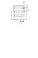
- FIG. 1 is a plan view of a temperature display label according to the embodiment.
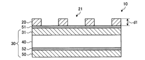
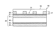
- FIG. 2 is a cross-sectional view taken along the line II-II ′ of FIG.
- FIG. 3 is a schematic cross-sectional view of the temperature display layer.
- FIG. 4 is a plan view for explaining an example of the temperature display of the temperature display label.
- FIG. 5 is a plan view for explaining another example of the temperature display of the temperature display label.
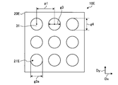
- FIG. 6 is a plan view of a temperature display label according to the first modification.
- FIG. 7 is a plan view of a temperature display label according to the second modification.
- FIG. 8 is a plan view of a temperature display label according to the third modification.
- FIG. 9 is a plan view of a temperature display label according to the fourth modification.
- FIG. 1 is a plan view of a temperature display label according to the embodiment.
- FIG. 2 is a cross-sectional view taken along the line II-II ′ of FIG.
- FIG. 3 is
- FIG. 10 is a plan view of a temperature display label according to the fifth modification.
- FIG. 11 is a cross-sectional view of a temperature display label according to a sixth modification.
- FIG. 12 is a cross-sectional view of a temperature display label according to the seventh modification.
- FIG. 13 is a cross-sectional view of the food packaging container according to the embodiment.
- FIG. 14 is an explanatory diagram showing an example of a heating method using a food packaging container.
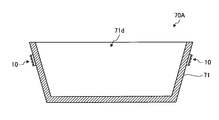
- FIG. 15 is a cross-sectional view of a food packaging container according to a first modification.
- FIG. 16 is a cross-sectional view of a food packaging container according to a second modification.
- FIG. 17 is a cross-sectional view of a food packaging container according to a third modification.
- FIG. 15 is a cross-sectional view of a food packaging container according to a first modification.
- FIG. 16 is a cross-sectional view of a food packaging container according to a second modification.
- FIG. 18 is a cross-sectional view of a food packaging container according to a fourth modification.
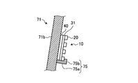
- FIG. 19 is a cross-sectional view showing an example of a method for attaching a temperature display label.
- FIG. 20 is a front view showing an example of a method for attaching a temperature display label.
- Drawing 21 is a flowchart for explaining an example of the manufacturing method of the packaging container for foods concerning an embodiment.
- FIG. 22 is a process diagram for explaining the method for manufacturing the food packaging container according to the first modification.
- FIG. 23 is a process diagram for explaining the manufacturing method of the food packaging container according to the second modification.
- FIG. 1 is a plan view of a temperature display label according to the embodiment.
- 2 is a cross-sectional view taken along the line II-II ′ of FIG.
- the temperature display label 10 of the present embodiment is used when heating food (for example, frozen food for general household use, frozen food for business use, processed food such as cooked rice for a range), etc., with an electromagnetic cooking device such as a microwave oven. Used to visually indicate whether food is at the right temperature.
- the temperature display label 10 of the present embodiment includes a temperature display layer 31 and a conductor layer 20.
- the temperature display layer 31 displays the temperature by changing the color according to the temperature of the food to be measured. A specific example of the configuration of the temperature display layer 31 will be described later.
- the conductor layer 20 is disposed on one surface of the temperature display layer 31 and has a function as a shield material that suppresses transmission of microwaves generated from the electromagnetic cooking device. In the present embodiment, the conductor layer 20 has a square shape.
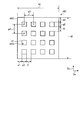
- a direction along one side of the conductor layer 20 is defined as a first direction Dx, and a direction orthogonal to the first direction Dx is defined as a second direction Dy.
- a plurality of openings 21 are provided in the conductor layer 20.
- a plurality of openings 21 are arranged in the first direction Dx and a plurality of openings 21 are arranged in the second direction Dy.
- the conductor layer 20 includes a first strip 27 that extends in the first direction Dx and a second strip 28 that extends in the second direction Dy.
- a plurality of first strips 27 are arranged in the second direction Dy, and a plurality of second strips 28 intersect with the first strip 27 and are arranged in the first direction Dx.
- a region surrounded by the first strip portion 27 and the second strip portion 28 is the opening 21. The consumer can visually recognize the temperature display layer 31 through the plurality of openings 21.
- the temperature display label 10 has a configuration in which the conductor layer 20 is bonded to the temperature display seal 30 including the temperature display layer 31 via the adhesive layer 51.
- the temperature display seal 30 further includes a base material 40, a separator 50, and an adhesive layer 52.
- the temperature display layer 31 is provided on one surface of the substrate 40, and the conductor layer 20 is bonded to the opposite side of the substrate 40 with respect to the temperature display layer 31.
- the base material 40 for example, a film-like resin material can be used.
- the adhesive layer 51 is provided on the entire surface of the temperature display layer 31, the temperature display layer 31 can be visually recognized through the opening 21 of the conductor layer 20 by using a light-transmitting material as the adhesive layer 51. Yes.
- the present invention is not limited to this, and the adhesive layer 51 may not be provided in the opening 21, and the adhesive layer 51 may be provided only in a portion overlapping the conductor layer 20.
- the separator 50 is bonded to the other surface of the base material 40 via an adhesive layer 52.
- the separator 50 is peeled off, and the base material 40 of the temperature display label 10 is attached to the temperature measurement target or the container accommodating the temperature measurement target via the adhesive layer 52.
- the temperature display layer 31 and the conductor layer 20 are supported on the base material 40. For this reason, even if it is a case where the conductor layer 20 is made thin, handling of the temperature display label 10 is easy, and it can affix on the container which accommodates a foodstuff easily.
- FIG. 3 is a schematic cross-sectional view of the temperature display layer.
- a known temperature indicating ink can be used for the temperature display layer 31.
- the temperature display layer 31 includes a color material 32 that changes color according to temperature and a resin layer 33 that is an ink vehicle.
- the color material 32 is dispersed in the resin layer 33.
- the coloring material 32 is, for example, a leuco dye, a developer and a solvent encapsulated in a microcapsule.
- a leuco dye is a color-developing material of a temperature indicating ink and is an organic dye whose color is reversibly changed by oxidation-reduction.
- the developer is an acidic substance that combines with the leuco dye to cause color development. When the leuco dye and the developer come into contact with each other, the color is developed by the mutual enjoyment of electrons.
- the solvent has a function as a temperature control material. When the temperature exceeds a predetermined temperature, the solvent dissolves and intervenes between the leuco dye and the developer to separate the leuco dye and the developer. Thereby, the enjoyment of electrons between the leuco dye and the developer is suppressed, and the color development disappears.
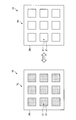
- FIG. 4 is a plan view for explaining an example of the temperature display of the temperature display label.
- the temperature display layer 31 develops color in a low temperature state TL lower than a predetermined temperature.
- the consumer can confirm that the food is insufficiently heated by visually recognizing the temperature display layer 31 through the opening 21.
- the temperature display layer 31 does not develop color.
- the color of the base material 40 (refer FIG. 2) is visually recognized because the temperature display layer 31 improves translucency. Thereby, the consumer can visually recognize the change in the color of the temperature display layer 31 through the opening 21 and can confirm that the food is at an appropriate temperature or higher.
- the temperature display layer 31 is colored when the temperature changes from the high temperature state TH to the low temperature state TL.
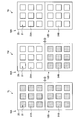
- FIG. 5 is a plan view for explaining another example of the temperature display of the temperature display label.
- a food is insufficiently heated (low temperature state TL) or more than an appropriate temperature (high temperature state TH) is displayed using a predetermined temperature as a threshold, but the present invention is not limited to this.
- the first temperature display label 10A has a first temperature display layer 31A
- the second temperature display label 10B has a second temperature display layer 31B.
- the first temperature display layer 31A uses a temperature indicating ink whose color changes at a predetermined first temperature
- the second temperature display layer 31B uses a temperature indicating ink whose color changes at a second temperature higher than the first temperature. ing.
- the first temperature display layer 31A and the second temperature display layer 31B are colored.
- the consumer can confirm that the food is insufficiently heated by visually recognizing the first temperature display layer 31 ⁇ / b> A and the second temperature display layer 31 ⁇ / b> B through the opening 21.
- an appropriate temperature state TM that is equal to or higher than the predetermined first temperature and lower than the second temperature
- the first temperature display layer 31A does not develop color
- the second temperature display layer 31B develops color.
- the consumer can confirm that the food is heated to an appropriate temperature by visually recognizing the first temperature display layer 31A and the second temperature display layer 31B.
- the first temperature display layer 31A and the second temperature display layer 31B do not color.
- the consumer can confirm that the food is heated excessively by visually recognizing the first temperature display layer 31A and the second temperature display layer 31B.
- the temperature state of the food can be accurately grasped.
- two types of temperature display labels are used, it is not limited to this, You may use three or more types of temperature display labels.
- the microwave of microwave oven is irradiated to the temperature display layer 31 without providing the conductor layer 20
- the solvent contained in the color material 32 may be dissolved before reaching the predetermined temperature.
- the temperature display layer 31 using the temperature indicating ink is used in a microwave oven, the color disappears before reaching a predetermined temperature, and it may not be possible to confirm whether the temperature of the food has risen. is there.
- the conductor layer 20 that functions as a shield material is provided on one surface of the temperature display layer 31.
- the conductor layer 20 is made of a metal material having good conductivity.
- aluminum, copper, or an alloy material containing one or more of these can be used.
- the aluminum material a so-called 1000-based material having an aluminum content of 90 wt% (mass%) or more can be used. Note that the present invention is not limited to this, and a so-called 2000 series to 7000 series aluminum material may be used.
- the shielding effect of the conductor layer 20 is represented by the following formula (1).
- the shielding effect indicates that the electric field intensity of the microwave that passes through the conductor layer 20 is reduced by S (dB) with respect to the electric field intensity of the incident microwave.
- t is the length t1 (mm) of the side of the conductor layer 20
- g is the length g1 (mm) of the side of the opening 21
- p is the first direction of the opening 21.
- d is the thickness d1 (mm) of the conductor layer 20.
- the conductor layer 20 and the opening 21 are each square, the length t1 of the side along the first direction Dx of the conductor layer 20 and the length of the side along the second direction Dy. It is the same as t2.
- the side length g1 and the side length g2 of the opening 21 are the same, and the arrangement pitch p1 and the arrangement pitch p2 are the same.
- the arrangement pitch p1 of the openings 21 is the distance between the centers 21X of the openings 21 adjacent in the first direction Dx, with the position where the diagonal line 21L of the openings 21 intersects being the center 21X of the openings 21.
- the interval between the opposing sides of the openings 21 adjacent in the first direction Dx is the length f1, and the interval between the opposing sides of the openings 21 adjacent in the second direction Dy is long.
- F2 The distance between the side of the conductor layer 20 along the second direction Dy and the side of the opening 21 is a length e1, and the distance between the side of the conductor layer 20 along the first direction Dx and the side of the opening 21 is long.
- Formula (1) is materialized when the length g1 of the opening 21 is smaller than (lambda) / 6 when the wavelength of a microwave is set to (lambda).
- the value of the shield effect S is a calculated value and may be different from the actual shield effect.
- the microwave shielding performance can be improved.
- the shielding effect S 22 dB.
- the shielding effect S 23 dB.
- the shielding effect S 29 dB.
- the thickness d1 1 mm
- the shielding effect S 35 dB.
- the thickness d1 of the conductor layer 20 is preferably 0.005 mm or more and 0.5 mm or less.
- the thickness d1 of the conductor layer 20 is 0.05 mm or more and 0.5 mm or less, for example, 0.08 mm. If it carries out like this, when sticking the temperature display label 10 on the container etc. which accommodate a foodstuff, handling is easy. More preferably, the total thickness of the temperature display label 10 is preferably 0.5 mm or less.
- the thickness d1 of the conductor layer 20 By setting the thickness d1 of the conductor layer 20 to 0.5 mm or less, the size of the step formed by the upper surface of the conductor layer 20, the side surface of the opening 21, and the upper surface of the temperature display layer 31 can be reduced. it can. For this reason, even if it is a case where the temperature display label 10 is used in an electromagnetic wave cooking appliance, concentration of a microwave can be suppressed and generation
- the temperature display label 10 of the present embodiment includes the temperature display layer 31 whose color changes according to the temperature, and the conductor provided with the plurality of openings 21 provided on one surface of the temperature display layer 31.
- Layer 20 Since the conductor layer 20 suppresses transmission of microwaves generated from the microwave oven, microwaves reaching the temperature display layer 31 are reduced, and discoloration of the temperature display layer 31 due to microwave irradiation can be suppressed. Therefore, even when the temperature display label 10 is used in a microwave oven, the temperature of the temperature measurement target such as food can be appropriately displayed by the change in the color of the temperature display layer 31. Further, since the conductor layer 20 is provided with a plurality of openings 21, the consumer can visually recognize the temperature display layer 31 through the openings 21.
- FIG. 6 is a plan view of a temperature display label according to the first modification.
- the temperature display label 10C of this modification is different from the conductor layer 20 shown in FIG. 1 in the outer dimensions of the conductor layer 20C and the number and size of the openings 21C.
- each of the conductor layer 20C and the opening 21C has a square shape.
- the shielding effect S 35 dB based on the formula (1). That is, it was shown that the intensity of the electromagnetic wave transmitted through the conductor layer 20C is reduced to about 2% or less.
- the area g of the conductor layer 20C occupying the unit area is increased by reducing the length g1 of the side of the opening 21C of the conductor layer 20C. Therefore, the temperature display label 10 shown in FIG. The shielding effect can be enhanced.
- the length g1 of the side of the opening 21C is smaller than 1 mm, the visibility of the temperature display layer 31 may be lowered. Therefore, the length g1 of the side of the opening 21C is desirably 1 mm or more.
- FIG. 7 is a plan view of a temperature display label according to the second modification.
- the temperature display label 10D of this modification differs from the conductor layer 20 shown in FIG. 1 in the outer dimensions of the conductor layer 20D and the number and size of the openings 21D.
- each of the conductor layer 20D and the opening 21D has a square shape.
- the shielding effect S 23 dB based on the formula (1). That is, it was shown that the intensity of the electromagnetic wave transmitted through the conductor layer 20D is reduced to about 7%.
- the shielding effect S 22 dB
- the shielding effect S 26 dB
- the shielding effect S 31 dB.
- Increasing the arrangement pitch p1 of the openings 21D that is, increasing the lengths f1 and f2 between the adjacent sides of the adjacent openings 21D increases the metal area and improves the shielding effect, but the visibility of the temperature display layer 31 is improved. May be reduced. For this reason, the arrangement pitch p1 of the openings 21D is preferably 5 mm or less.
- FIG. 8 is a plan view of a temperature display label according to the third modification.
- the opening 21E is circular.
- g is the diameter g3 of the opening 21E
- p is the arrangement pitch p1 of the centers of the openings 21E arranged in the first direction Dx.
- the shield effect S is computable based on Formula (1) similarly to the case of square-shaped opening 21, 21C, 21D.
- the diameter g3 is desirably 1 mm or more and 3 mm or less. In this way, visibility of the temperature display layer 31 can be ensured while suppressing transmission of microwaves through the conductor layer 20E.
- the circular opening 21E was shown, it is not limited to this.
- the opening 21E may have an oval shape, an oval shape, or the like in which the length g3a in the first direction Dx and the length g4 in the second direction Dy are different.
- g is the length of the opening 21E in the longitudinal direction.
- FIG. 9 is a plan view of a temperature display label according to the fourth modification.
- the opening 21F has a rectangular shape. That is, the length g1 of the side along the first direction Dx of the opening 21F is longer than the length g2 of the side along the second direction Dy.
- g is the length g1 of the side along the longitudinal direction of the opening 21F, that is, the first direction Dx
- p is the arrangement pitch p1 in the longitudinal direction.
- the length in the longitudinal direction (the length g1 of the side along the first direction Dx) is preferably 3 mm or less in order to improve the shielding performance.
- the length in the lateral direction (side length g2 along the second direction Dy) is 1 mm or more.
- FIG. 10 is a plan view of a temperature display label according to the fifth modification.
- the outer diameter shape of the conductor layer 20-20F described above is a square shape, but is not limited thereto.
- the conductor layer 20G has a rectangular shape. That is, the length t1 of the side along the first direction Dx of the conductor layer 20G is longer than the length t2 of the side along the second direction Dy.
- t is the length t2 in the short direction of the conductor layer 20G.
- the outer diameter shape of the conductor layer 20G is not limited to a rectangular shape, and may be, for example, a polygonal shape, a circular shape, an elliptical shape, or the like.
- the opening 21G is square, but may be rectangular or circular as described above.
- the temperature display label 10G of the present modified example by appropriately changing the shape of the conductor layer 20G, it can be easily attached according to the shape and measurement position of the food packaging container to be attached, The temperature of the food can be displayed.
- FIG. 11 is a cross-sectional view of a temperature display label according to a sixth modification.
- the first conductor layer 22 is provided on one surface of the temperature display layer 31, and the substrate 40 is disposed on the other surface of the temperature display layer 31 opposite to the one surface.
- a second conductor layer 23 is provided therebetween.
- the first conductor layer 22 is bonded to the temperature display layer 31 via the adhesive layer 51.
- the second conductor layer 23 is bonded to the base material 40 via the adhesive layer 52.
- the first conductor layer 22 can have any one of the above-described conductor layers 20-20G.
- the second conductor layer 23 may be the same as the first conductor layer 22 or may be configured differently from the first conductor layer 22.
- the microwave shielding effect can be improved. That is, the microwave irradiated from one surface of the temperature display layer 31 is shielded by the first conductor layer 22, and the microwave irradiated from the other surface of the temperature display layer 31 is shielded by the second conductor layer 23. Is done.
- any surface may be affixed when it affixes on a food packaging container etc., the convenience is improved.
- the consumer can visually recognize the temperature display layer 31 through the opening 24.
- the consumer can use the light-transmitting material as the base material 40, so that the consumer can display the temperature display layer 31 through the opening 25 of the second conductor layer 23. Can be visually recognized.
- FIG. 12 is a cross-sectional view of a temperature display label according to the seventh modification.
- an insulating layer 54 is provided so as to cover the conductor layer 20.
- the insulating layer 54 is provided on the entire conductor layer 20 across the upper surface of the conductor layer 20 and the opening 21.
- a resin film material having translucency is used for the insulating layer 54.
- FIG. 13 is a cross-sectional view of the food packaging container according to the embodiment.
- FIG. 14 is an explanatory diagram showing an example of a heating method using a food packaging container.
- the food packaging container 70 of the present embodiment includes a package 71 that contains a temperature-measurement target such as food, and a temperature display label 10.
- the package 71 includes a bottom plate 71a and a side plate 71b provided on the periphery of the bottom plate 71a.
- the side plate 71b is provided to be inclined so as to spread upward.
- An object to be measured such as food is accommodated in a recess 71d formed by the bottom plate 71a and the side plate 71b.
- the temperature display label 10 is bonded to the outer surface of the side plate 71b.
- the base material 40 (not shown in FIG. 13) shown in FIG. 2 is bonded to the side plate 71b via the adhesive layer 52, so that the temperature display layer 31 and the conductor layer are formed outward from the outer peripheral surface of the side plate 71b. They are arranged in the order of 20.
- the microwave is irradiated to the food from the microwave generator 101.
- the heat of the food is transmitted to the temperature display label 10 through the side plate 71b, and the color of the temperature display layer 31 (see FIG. 13) of the temperature display label 10 is changed according to the heating state of the food. Change.
- the microwaves irradiated to the temperature display label 10 from the outer surface side of the side plate 71b are shielded by the conductor layer 20 and are prevented from passing through the temperature display layer 31.
- the microwave irradiated to the temperature display label 10 from the inner surface side of the side plate 71 b is suppressed by being absorbed by food or the like and transmitted to the temperature display layer 31. Thereby, discoloration of the temperature display layer 31 due to microwave irradiation is suppressed, and the temperature of the food or the like is appropriately displayed.
- the temperature display label 10 is disposed on the inner side of the end 71c of the side plate 71b. Thereby, since the conductor layer 20 of the temperature display label 10 does not contact the inner wall of the microwave oven 100 during heating in the microwave oven 100, generation
- FIG. 15 is a cross-sectional view of a food packaging container according to a first modification.
- a plurality of temperature display labels 10 are provided on the package 71.
- two temperature display labels 10 are provided.
- One temperature display label 10 is disposed opposite to the other temperature display label 10 with a recess 71d for containing food therebetween.
- the temperature display label 10 is not limited to one or two, and three or more temperature display labels 10 may be provided.
- a plurality of temperature display labels 10 are provided, it is possible to confirm the occurrence of uneven heating of food. Further, in the case of a mechanism that is placed on a rotary table (not shown) of the microwave oven 100 and heated, it becomes easy to visually recognize the temperature display label 10 during heating.
- FIG. 16 is a cross-sectional view of a food packaging container according to a second modification.
- the packaging body 71 further includes a lid body 71e that covers the recess 71d.
- the temperature display label 10 is affixed on the upper surface of the lid 71e.
- the food is heated in a state where it is contained in an internal space surrounded by the bottom plate 71a, the side plate 71b, and the lid 71e.
- heat such as water vapor generated from the food is transmitted to the temperature display label 10 through the lid 71e.
- the “packaging body” is a form used for ordinary foods, for example, a container body including a bottom plate 71a and a side plate 71b, a lid body 71e covering the container body, a packaging body, and the like. Includes items that contain food, such as bags.
- FIG. 17 is a cross-sectional view of a food packaging container according to a third modification.
- the food packaging container 70 ⁇ / b> C of this modification includes a dish-shaped package 72 and the temperature display label 10.
- the package 72 includes a bottom plate 72a, a side plate 72b provided on the periphery of the bottom plate 72a, and an overhang portion 72c that projects outward from the upper end of the side plate 72b. Food or the like is stored in a recess 72e formed by the bottom plate 72a and the side plate 72b.
- the temperature display label 10 is provided on the upper surface 72d of the overhang portion 72c.
- the temperature display label 10 is arranged in the order of the base material 40 (not shown in FIG. 17), the temperature display layer 31, and the conductor layer 20 from the upper surface 72d.
- the microwave of the microwave oven 100 is irradiated from the upper side of the food packaging container 70C, and is less likely to be irradiated from the lower side of the food packaging container 70C. Even in such an embodiment, since microwaves that pass through the conductor layer 20 and reach the temperature display layer 31 are suppressed, discoloration of the temperature display layer 31 due to microwave irradiation is suppressed, and the temperature of the food or the like Is displayed properly.
- the temperature display label 10 is provided in a state closer to the food to be heated.
- the temperature display label 10 is preferably provided on the inner side in the radial direction of the overhang portion 72c. If it carries out like this, the temperature display label 10 can reflect the heating state of a foodstuff, and can display temperature appropriately.
- a bent portion is formed at a connection portion between the overhang portion 72c and the side plate 72b. When the temperature display label 10 is affixed to the bent portion, sparks may occur. Therefore, it is preferable to affix the temperature display label 10 on the smooth surface of the package 72.
- FIG. 18 is a cross-sectional view of a food packaging container according to a fourth modification.
- the food packaging container 70 ⁇ / b> D of this modification includes a packaging bag 73 and a temperature display label 10.
- a packaging bag 73 can cope with microwave heating, and can be directly heated by the microwave oven 100 without transferring the food inside to another container.
- the temperature display label 10 is provided on the outer surface of the packaging bag 73, and the consumer recognizes whether the food contained in the packaging bag 73 has been heated to an appropriate temperature due to the color change of the temperature display label 10. can do.
- FIG. 19 is a cross-sectional view showing an example of a method for attaching a temperature display label.
- FIG. 20 is a front view showing an example of a method for attaching a temperature display label.
- an attachment portion 75 is provided on the outer surface of the side plate 71 b of the package 71.
- the attachment portion 75 has a first portion 75a and a second portion 75b.
- the first portion 75a protrudes from the side plate 71b.
- the second portion 75b is provided at the end of the first portion 75a and extends in a direction parallel to the side plate 71b.
- the temperature display label 10 is placed on the first portion 75a and fixed between the second portion 75b and the side plate 71b.
- the attachment portion 75 is provided so as to overlap with at least three sides of the temperature display label 10, and the temperature display label 10 is accommodated in a space surrounded by the attachment portion 75. At this time, it is preferable that the second portion 75 b of the attachment portion 75 does not overlap the opening 21 of the conductor layer 20. In this way, the visibility of the temperature display layer 31 can be ensured.
- the attachment part 75 for attaching the temperature display label 10 to the package 71 since the attachment part 75 for attaching the temperature display label 10 to the package 71 is provided, it is not necessary to provide the adhesive layer 52 (see FIG. 2) on the base material 40 of the temperature display label 10, and the temperature The configuration of the display label 10 can be simplified. Moreover, by using reversible temperature indicating ink as the temperature display layer 31 as described above, it is possible to attach it to another package 71 after the temperature display label 10 and use it repeatedly.
- Drawing 21 is a flowchart for explaining an example of the manufacturing method of the packaging container for foods concerning an embodiment.
- a metal sheet 81 such as aluminum is prepared (step ST11), and a plurality of openings 21 are formed in the metal sheet 81 by pressing or the like (step ST12).
- the circular opening 21 is formed, but a square shape, a rectangular shape, a polygonal shape, or the like may be used.
- the formation method of the opening 21 is not limited to press work.
- the opening 21 may be formed by piercing a roll-shaped metal sheet 81, or a method of opening a slit to open the left and right.
- the temperature display seal 30 is prepared in a separate process from the drilling of the metal sheet 81 (step ST13). As shown in FIG. 2, the temperature display seal 30 is used in which the temperature display layer 31 is provided on one surface of the base material 40 and the separator 50 is bonded to the other surface via the adhesive layer 52. (A detailed configuration is omitted in FIG. 21). Then, the adhesive layer 51 is applied to the surface of the temperature display seal 30 (step ST14).
- the metal sheet 81 is bonded to the temperature display seal 30 via the adhesive layer 51 (step ST15). Then, the bonded temperature display seal 30 and the metal sheet 81 are cut into individual pieces to form a plurality of temperature display labels 10 including the temperature display seal 30 and the conductor 20 (step ST16).
- a resin sheet 82 which is a material of the package 71, is prepared in a process separate from the process of forming the temperature display label 10 (step ST21).
- a resin material such as polypropylene can be used.
- the individual sheet 82a is formed by punching the resin sheet 82 (step ST22).
- FIG. 21 shows an example in which one piece sheet 82a is punched, a large number of piece sheets 82a may be formed from the resin sheet 82.
- the package 71 is formed by press-molding the individual sheet 82a (step ST23).
- press forming is performed after the punching of the individual sheet 82a.
- the present invention is not limited to this.
- a process of cutting the individual packaging bodies 71 may be performed.
- the food packaging container 70 is formed by attaching the temperature display label 10 to the side surface of the package 71 (step ST24).
- the food packaging container 70 can be manufactured through the steps described above.
- FIG. 22 is a process diagram for explaining the method for manufacturing the food packaging container according to the first modification.
- Drilling of the metal sheet 81 (steps ST11 and ST12), a process of applying the adhesive layer 51 to the temperature display seal 30 (step ST14), and a process of forming a plurality of temperature display labels 10 (steps ST15 and ST16) are shown in FIG. This is the same as the process described in FIG. Further, the process of forming the food packaging container 70 by pressing the package 71 (steps ST21 to ST24) is the same as the process described in FIG.
- a base material 40 is prepared (step ST13-1).
- the base material 40 includes an adhesive layer 52 and a separator 50 (see FIG. 2) (not shown).
- the temperature display layer 31 is applied to one surface of the substrate 40, that is, the surface opposite to the surface on which the adhesive layer 52 and the separator 50 are provided (step ST13-2).
- the temperature display layer 31 can be applied by using the above-described temperature indicating ink, for example, by a printing method such as screen printing or inkjet printing. Thereby, the temperature display seal
- the degree of freedom in designing the temperature display layer 31 can be increased. That is, by appropriately setting a region where the temperature display layer 31 is provided, such as by coating and forming the temperature display layer 31 only in a region overlapping with the opening 21, the amount of the temperature indicating ink can be reduced and the manufacturing cost can be suppressed. Further, it is easy to appropriately select the temperature indicating ink according to the food contained in the food packaging container 70.
- FIG. 23 is a process diagram for explaining the manufacturing method of the food packaging container according to the second modification.
- a metal sheet 81 is prepared (step ST41), and a plurality of openings 21 are formed in the metal sheet 81 by pressing or the like (step ST42).
- the conductor layer 20 is formed by cutting the metal sheet 81 provided with a plurality of openings 21 into pieces (step ST43).
- a resin sheet 82 that is a material of the package 71 is prepared (step ST51).
- the individual sheet 82a is formed by punching the resin sheet 82 (step ST52).
- the package 71 is formed by press-molding the piece sheet 82a (step ST53).
- the temperature display layer 31 is applied to the side surface of the package 71 (step ST54). In this modification, it can apply
- the adhesive layer 51 is applied to the conductor layer 20 (step ST44), and the conductor layer 20 is attached to the surface of the temperature display layer 31 of the package 71 (step ST55). Thereby, the food packaging container 70 is formed.
- the temperature display layer 31 is formed directly on the package 71, so that the step of bonding the temperature display seal 30 and the conductor layer 20 can be omitted, and the manufacturing process can be simplified. Moreover, the base material 40 and the separator 50 can be omitted, and the manufacturing cost can be suppressed.
- the temperature display label 10 is a temperature display label 10 for displaying the temperature of a temperature measurement target heated by an electromagnetic cooking device such as the microwave oven 100, and the temperature display label 10.
- a temperature display layer 31 whose color changes in response to the temperature display layer 31 and a conductor layer 20 provided on one surface of the temperature display layer 31 and provided with a plurality of openings 21 are provided.
- the temperature display label 10 can appropriately display the temperature to be measured by the change in the color of the temperature display layer 31.
- the conductor layer 20 has a plurality of rectangular openings 21 arranged in a row. According to this, it is possible to satisfactorily visually recognize the temperature display layer 31 through the opening 21 while suppressing the transmission of microwaves by the conductor layer 20.
- the length of one side of the opening 21 is 1 mm or more and 3 mm or less. According to this, the visibility of the temperature display layer 31 can be ensured while suppressing a decrease in shielding performance due to the conductor layer 20.
- the conductor layer 20E has a plurality of circular openings 21E arranged. According to this, it is possible to satisfactorily visually recognize the temperature display layer 31 through the opening 21E while suppressing the transmission of microwaves by the conductor layer 20E.
- the diameter of the opening 21E is 1 mm or more and 3 mm or less. According to this, visibility of the temperature display layer 31 can be ensured while suppressing a decrease in shielding performance due to the conductor layer 20E.
- the thickness of the conductor layer 20 is 0.005 mm or more and 0.5 mm or less. According to this, it can affix on the package 71 etc. which accommodate the foodstuff which is a temperature measured object, suppressing the permeation
- FIG. 1 the thickness of the conductor layer 20 is 0.005 mm or more and 0.5 mm or less. According to this, it can affix on the package 71 etc. which accommodate the foodstuff which is a temperature measured object, suppressing the permeation
- the conductor layer 20 is aluminum or an alloy thereof. According to this, since the conductor layer 20 has favorable electroconductivity and heat conductivity, the temperature display layer 31 can display temperature appropriately. Moreover, the opening 21 of the conductor layer 20 can be easily processed.
- the substrate 40 is provided on the other surface of the temperature display layer 31 opposite to the one surface. According to this, since the base material 40 supports the temperature display layer 31 and the conductor layer 20, the temperature display layer 31 and the conductor layer 20 are easily attached to the packaging body 71 or the like via the base material 40. Can be attached.
- the second conductor layer 23 is provided on the other surface of the temperature display layer 31 through the base material 40. According to this, the microwave irradiated from the other surface of the temperature display layer 31 can be suppressed.
- the food packaging container 70 of the present embodiment includes the temperature display label 10 according to any one of the above and a packaging body 71 that contains the food, and the temperature display label 10 is provided on the outer peripheral surface of the packaging body 71.
- the temperature display layer 31 is disposed between the conductor layer 20 and the package 71. According to this, since the conductor layer 20 suppresses transmission of microwaves generated from the electromagnetic cooking device, discoloration of the temperature display layer 31 due to microwave irradiation can be suppressed. Therefore, the temperature display label 10 can appropriately display the temperature of the food stored in the package 71 by the color change of the temperature display layer 31.
- the manufacturing method of the food packaging container of the present embodiment includes a step (step ST54) of applying the temperature display layer 31 whose color changes according to the temperature to the package 71 that contains the food, and the surface of the temperature display layer 31. And a step of bonding the conductor layer 20 provided with the plurality of openings 21 (step ST55). According to this, since the temperature display layer 31 is provided in the package 71 without the base material 40 etc., a structure can be simplified and manufacturing cost can be reduced.
Landscapes
- Engineering & Computer Science (AREA)
- Physics & Mathematics (AREA)
- General Physics & Mathematics (AREA)
- Mechanical Engineering (AREA)
- Theoretical Computer Science (AREA)
- Packages (AREA)
- Measuring Temperature Or Quantity Of Heat (AREA)
- Details Of Rigid Or Semi-Rigid Containers (AREA)
- Package Specialized In Special Use (AREA)
Abstract
温度表示ラベルは、電磁波調理機器で加熱される被測温対象の温度を表示するための温度表示ラベルであって、温度に応じて色が変化する温度表示層と、温度表示層の一方の面に配置され、複数の開口が設けられた第1導体層とを有することを特徴とする。
Description
本発明は、温度表示ラベル、食品用包装容器及び食品用包装容器の製造方法に関する。
食品の温度管理を行うために、所定の温度で色が変化する示温インキを含む温度表示ラベルが用いられている。消費者は、温度表示ラベルの色の変化を視認して食品の加熱状態を把握することができる。例えば、下記特許文献1には、示温インキを含む温度計が備えられたPETボトル等の容器入り飲料が記載されている。
食品を電子レンジ等の電磁波調理機器で温める際、電磁波調理機器の出力のバラツキや、食品の温度や量により、加熱不足が発生する場合がある。示温インキを用いた温度表示ラベルは、電磁波調理機器のマイクロ波によって示温インキが変色するため、電磁波調理機器で加熱する食品用包装容器に用いることが困難である。特許文献1の示温インキを含む温度計は、電子レンジで加熱する前の飲料の温度を把握して、温度に応じて電子レンジの作動時間を適切に設定するために設けられており、電子レンジで使用する際の温度を把握することは困難である。
本発明は、電磁波調理機器で使用する際に、適切に被測温対象の温度を表示することが可能な温度表示ラベル、食品用包装容器及び食品用包装容器の製造方法を提供することを目的とする。
本発明の一態様に係る温度表示ラベルは、電磁波調理機器で加熱される被測温対象の温度を表示するための温度表示ラベルであって、温度に応じて色が変化する温度表示層と、前記温度表示層の一方の面に配置され、複数の開口が設けられた第1導体層とを有することを特徴とする。
これによれば、複数の開口が設けられた第1導体層は、電磁波調理機器から発生するマイクロ波の透過を抑制するので、マイクロ波の照射による温度表示層の変色を抑制することができる。したがって、温度表示ラベルは、温度表示層の色の変化により被測温対象の温度を適切に表示することができる。
本発明の望ましい態様に係る温度表示ラベルにおいて、前記第1導体層は、矩形状の前記開口が複数配列されている。これによれば、第1導体層によりマイクロ波の透過を抑制しつつ、開口を通して温度表示層を良好に視認することができる。
本発明の望ましい態様に係る温度表示ラベルにおいて、前記開口の一辺の長さは1mm以上、3mm以下である。これによれば、第1導体層によるシールド性能の低下を抑制しつつ、温度表示層の視認性を確保することができる。
本発明の望ましい態様に係る温度表示ラベルにおいて、前記第1導体層は、円形状の前記開口が複数配列されている。これによれば、第1導体層によりマイクロ波の透過を抑制しつつ、開口を通して温度表示層を良好に視認することができる。
本発明の望ましい態様に係る温度表示ラベルにおいて、前記開口の直径は1mm以上、3mm以下である。これによれば、第1導体層によるシールド性能の低下を抑制しつつ、温度表示層の視認性を確保することができる。
本発明の望ましい態様に係る温度表示ラベルにおいて、前記第1導体層の厚さは、0.005mm以上、0.5mm以下である。これによれば、第1導体層によりマイクロ波の透過を抑制しつつ、被測温対象又は被測温対象を収容する容器等に容易に配置することができる。
本発明の望ましい態様に係る温度表示ラベルにおいて、前記第1導体層は、アルミニウム又はその合金である。これによれば、第1導体層は、良好な導電性及び熱伝導性を有するので、温度表示層は適切に温度を表示することができる。また、第1導体層の開口の加工を容易に行うことができる。
本発明の望ましい態様に係る温度表示ラベルにおいて、前記温度表示層の、前記一方の面と反対側の他方の面に基材が設けられている。これによれば、基材は、温度表示層と第1導体層とを支持しているため、被測温対象又は被測温対象を収容する容器等に、基材を介して温度表示層及び第1導体層を容易に配置することができる。
本発明の望ましい態様に係る温度表示ラベルにおいて、前記温度表示層の前記他方の面に、前記基材を介して第2導体層が設けられている。これによれば、温度表示層の他方の面から照射されるマイクロ波を抑制することができる。
本発明の一態様に係る食品用包装容器は、上記のいずれかに記載の温度表示ラベルと、食品を収容する包装体と、を備え、前記温度表示ラベルは、前記包装体の外側の面に設けられ、前記温度表示層は、前記第1導体層と前記包装体との間に配置されることを特徴とする。これによれば、第1導体層は、電磁波調理機器から発生するマイクロ波の透過を抑制するので、マイクロ波の照射による温度表示層の変色を抑制することができる。したがって、温度表示ラベルは、温度表示層の色の変化により包装体に収容された食品の温度を適切に表示することができる。
本発明の一態様に係る食品用包装容器の製造方法は、食品を収容する包装体に、温度に応じて色が変化する温度表示層を塗布する工程と、前記温度表示層の表面に、複数の開口が設けられた導体層を貼り合わせる工程と、を有することを特徴とする。これによれば、温度表示層が、基材等を介さずに包装体に設けられるので、構成を簡略化して、製造コストを低減することができる。
本発明の温度表示ラベル、食品用包装容器及び食品用包装容器の製造方法によれば、電磁波調理機器で使用する際に、適切に被測温対象の温度を表示することができる。
以下、本発明に係る実施形態について図面を参照しながら説明するが、本発明はこれに限定されない。以下で説明する実施形態の構成要素は、適宜組み合わせることができる。また、一部の構成要素を用いない場合もある。また、以下で説明する実施形態における構成要素には、当業者が容易に想定できるもの、実質的に同一のもの、いわゆる均等の範囲のものが含まれる。
(温度表示ラベル)
図1は、実施形態に係る温度表示ラベルの平面図である。図2は、図1のII-II’線で切断して矢印方向から見たときの断面図である。本実施形態の温度表示ラベル10は、電子レンジ等の電磁波調理機器で食品(例えば、一般家庭用の冷凍食品、業務用の冷凍食品、レンジ用ごはん等の加工食品)等を加熱する際に、食品が適温であるか視覚的に表示するために用いられる。
図1は、実施形態に係る温度表示ラベルの平面図である。図2は、図1のII-II’線で切断して矢印方向から見たときの断面図である。本実施形態の温度表示ラベル10は、電子レンジ等の電磁波調理機器で食品(例えば、一般家庭用の冷凍食品、業務用の冷凍食品、レンジ用ごはん等の加工食品)等を加熱する際に、食品が適温であるか視覚的に表示するために用いられる。
図1に示すように、本実施形態の温度表示ラベル10は、温度表示層31と、導体層20とを含む。温度表示層31は、被測温対象である食品の温度に応じて色が変化することで温度を表示する。温度表示層31の構成の具体例については後述する。導体層20は、温度表示層31の一方の面に配置され、電磁波調理機器から発生するマイクロ波の透過を抑制するシールド材としての機能を有する。本実施形態において、導体層20は正方形状である。
ここで、導体層20の一辺に沿った方向を第1方向Dxとし、第1方向Dxに直交する方向を第2方向Dyとする。導体層20には複数の開口21が設けられている。開口21は、第1方向Dxに複数配列されるとともに、第2方向Dyに複数配列される。言い換えると、導体層20は、第1方向Dxに延びる第1帯状部27と、第2方向Dyに延びる第2帯状部28とを含む。第1帯状部27は、第2方向Dyに複数配列され、第2帯状部28は、第1帯状部27と交差するとともに、第1方向Dxに複数配列される。第1帯状部27と第2帯状部28とで囲まれた領域が開口21である。消費者は、複数の開口21を通して温度表示層31を視認することが可能となっている。
図2に示すように、温度表示ラベル10は、温度表示層31を含む温度表示シール30の上に、接着層51を介して導体層20が貼り合わされた構成となっている。温度表示シール30は、さらに基材40と、セパレータ50と、接着層52を含む。温度表示層31は、基材40の一方の面に設けられており、導体層20は、温度表示層31に対して基材40の反対側に貼り合わされている。基材40は、例えばフィルム状の樹脂材料を用いることができる。
接着層51は、温度表示層31の全面に設けられているが、接着層51として透光性を有する材料を用いることで、導体層20の開口21を通して温度表示層31が視認可能となっている。なお、これに限定されず、開口21において接着層51が設けられず、導体層20と重なる部分のみに接着層51が設けられていてもよい。
セパレータ50は、基材40の他方の面に接着層52を介して貼り合わされている。温度表示ラベル10を使用する際に、セパレータ50を剥離して、被測温対象又は被測温対象を収容する容器に接着層52を介して温度表示ラベル10の基材40が貼り付けられる。本実施形態において、基材40に温度表示層31及び導体層20が支持されている。このため、導体層20を薄くした場合であっても、温度表示ラベル10の取扱いが容易であり、食品を収容する容器に容易に貼り付けることができる。
図3は、温度表示層の模式断面図である。温度表示層31は、公知の示温インキを用いることができる。図3に示すように、温度表示層31は、温度に応じて色が変化する色材32と、インキビヒクルである樹脂層33とを含む。色材32は樹脂層33に分散されている。
色材32は、例えば、ロイコ系染料、顕色剤及び溶媒をマイクロカプセル化して封じ込めたものである。ロイコ系染料は、示温インキの発色体であり、酸化還元により可逆的に色が変化する有機色素である。顕色剤は、ロイコ系染料と結合して発色させる酸性物質である。ロイコ系染料と顕色剤とが接触すると互いの電子の享受により発色する。溶媒は、温度制御材としての機能を有する。所定の温度以上になると溶媒が溶けて、ロイコ系染料と顕色剤との間に介入して、ロイコ系染料と顕色剤とを引き離す。これにより、ロイコ系染料と顕色剤との間の電子の享受が抑制され、発色が消える。
図4は、温度表示ラベルの温度表示の一例を説明するための平面図である。上述した原理により、所定の温度よりも低い低温状態TLにおいて、温度表示層31は発色する。消費者は、開口21を通して温度表示層31を視認することで、食品が加熱不足であることを確認できる。所定の温度以上の高温状態THにおいて、温度表示層31は発色しない。この場合、温度表示層31は透光性が向上することで基材40(図2参照)の色が視認される。これにより、消費者は開口21を通して温度表示層31の色の変化を視認して、食品が適温以上であることを確認できる。また、温度表示層31に可逆性の示温インキを用いた場合、高温状態THから低温状態TLに温度が変化した場合、温度表示層31は発色する。
図5は、温度表示ラベルの温度表示の他の例を説明するための平面図である。図4に示す例では、ある所定の温度を閾値として食品が加熱不足(低温状態TL)であるか、適温以上(高温状態TH)であるかを表示するが、これに限定されない。図5に示すように、色が変化する温度が異なる第1温度表示ラベル10Aと第2温度表示ラベル10Bとを設けてもよい。第1温度表示ラベル10Aは第1温度表示層31Aを有し、第2温度表示ラベル10Bは第2温度表示層31Bを有する。第1温度表示層31Aは所定の第1温度で色が変化する示温インキが用いられ、第2温度表示層31Bは、第1温度よりも高い第2温度で色が変化する示温インキが用いられている。
図5に示すように、所定の第1温度よりも低い低温状態TLにおいて、第1温度表示層31A及び第2温度表示層31Bが発色する。消費者は、開口21を通して第1温度表示層31A及び第2温度表示層31Bを視認することで、食品が加熱不足であることを確認できる。所定の第1温度以上、かつ第2温度よりも低い適温状態TMにおいて、第1温度表示層31Aは発色せず第2温度表示層31Bは発色する。消費者は、第1温度表示層31A及び第2温度表示層31Bを視認することで、食品が適温に加熱されたことを確認できる。所定の第2温度以上の高温状態THにおいて、第1温度表示層31A及び第2温度表示層31Bは発色しない。消費者は、第1温度表示層31A及び第2温度表示層31Bを視認することで、食品が過剰に加熱されたことを確認できる。
このように、色が変化する温度が異なる第1温度表示ラベル10Aと第2温度表示ラベル10Bとを設けることで、食品の温度状態を的確に把握することができる。なお、図5に示す例では、2種類の温度表示ラベルを用いているが、これに限定されず、3種類以上の温度表示ラベルを用いてもよい。
ここで、仮に導体層20を設けずに、温度表示層31に電子レンジのマイクロ波が照射されると、色材32に含まれる溶媒が所定の温度に達する前に溶けてしまう場合がある。このため、示温インキを用いた温度表示層31を電子レンジに用いた場合、所定の温度に達する前に発色が消えることになり、食品の温度が上昇したかどうかを確認することができない場合がある。
本実施形態では、上述したように、温度表示層31の一方の面にシールド材として機能する導体層20が設けられている。導体層20は、良好な導電性を有する金属材料により形成されており、例えばアルミニウム、銅等、或いは、これらの1つ以上を含む合金材料を用いることができる。アルミニウム材料として、アルミニウムの含有率が90wt%(質量%)以上のいわゆる1000系の材料を用いることができる。なお、これに限定されず、いわゆる2000系から7000系のアルミニウム材料を用いてもよい。
次に、図1及び図2を参照しつつ、導体層20のシールド効果について説明する。導体層20のシールド効果は下記の式(1)で表される。シールド効果は、導体層20を透過するマイクロ波の電界強度が、入射するマイクロ波の電界強度に対してS(dB)だけ小さくなることを示している。

ここで、式(1)において、tは導体層20の辺の長さt1(mm)であり、gは開口21の辺の長さg1(mm)であり、pは開口21の第1方向Dxにおける配列ピッチp1(mm)であり、dは導体層20の厚さd1(mm)である。なお、本実施形態では、導体層20及び開口21をそれぞれ正方形状であるとしたため、導体層20の第1方向Dxに沿った辺の長さt1と、第2方向Dyに沿った辺の長さt2とは同じである。同様に開口21の辺の長さg1と辺の長さg2は同じであり、配列ピッチp1と配列ピッチp2とは同じである。開口21の配列ピッチp1は、開口21の対角線21Lが交差する位置を、開口21の中心21Xとして、第1方向Dxに隣り合う開口21の中心21Xどうしの間隔としている。
なお、図1に示すように、第1方向Dxに隣り合う開口21の対向する辺どうしの間隔は長さf1であり、第2方向Dyに隣り合う開口21の対向する辺どうしの間隔は長さf2である。また、第2方向Dyに沿う導体層20の辺と、開口21の辺との間隔を長さe1とし、第1方向Dxに沿う導体層20の辺と、開口21の辺との間隔を長さe2とする。本実施形態において、例えば、f1=f2=e1=e2=1mmとすることができる。
本実施形態において、t1=10mm、g1=2mm、p1=3mm、d=0.1mmとした場合、式(1)に基づいて、シールド効果S=23dBとなる。つまり、導体層20を透過する電磁波の強度は、約7%に低減されることが示された。
なお、式(1)は、マイクロ波の波長をλとしたときに、開口21の長さg1が、λ/6よりも小さい場合に成立する。ここで、例えば電子レンジのマイクロ波の周波数はf=2.45GHz、波長はλ=122mmである。また、シールド効果Sの値は計算値であり、実際のシールド効果とは異なる可能性がある。
導体層20の厚さd1は厚くなるほど、マイクロ波のシールド性能を向上させることができる。例えば、厚さd1=0.005mm以上、d1=0.05mm以下の場合、シールド効果S=22dBである。また、厚さd1=0.1mmの場合、シールド効果S=23dBである。厚さd1=0.5mmの場合、シールド効果S=29dBである。厚さd1=1mmの場合、シールド効果S=35dBである。ただし、導体層20の厚さd1は0.005mm以上、0.5mm以下であることが好ましい。より好ましくは、導体層20の厚さd1は0.05mm以上、0.5mm以下、例えば0.08mmである。こうすれば、温度表示ラベル10を食品を収容する容器等に貼り付ける場合に、取扱いが容易である。より好ましくは、温度表示ラベル10の全体の厚さを0.5mm以下とすることが好ましい。
導体層20の厚さd1を0.5mm以下とすることで、導体層20の上面と、開口21の側面と、温度表示層31の上面とで形成される段差の大きさを小さくすることができる。このため、温度表示ラベル10を電磁波調理機器内で使用した場合であっても、マイクロ波の集中を抑制して、スパークの発生を抑えることができる。また、スパークの発生を抑制するために、導体層20の上面と、開口21の側面とで形成される角部を滑らかにする、或いは、平面視における導体層20の外形の角部を滑らかにすることが好ましい。
以上のように、本実施形態の温度表示ラベル10は、温度に応じて色が変化する温度表示層31と、温度表示層31の一方の面に設けられ、複数の開口21が設けられた導体層20とを有する。導体層20は、電子レンジから発生するマイクロ波の透過を抑制するので、温度表示層31に到達するマイクロ波が低減され、マイクロ波の照射による温度表示層31の変色を抑制することができる。したがって、温度表示ラベル10は、電子レンジに用いられる場合であっても、温度表示層31の色の変化により食品等の被測温対象の温度を適切に表示することができる。また、導体層20は複数の開口21が設けられているので、消費者は、開口21を通して温度表示層31を視認することができる。
図6は、第1変形例に係る温度表示ラベルの平面図である。本変形例の温度表示ラベル10Cは、図1に示す導体層20に対して、導体層20Cの外形寸法、開口21Cの数及び大きさが異なる。なお、本変形例においても、導体層20C及び開口21Cは、それぞれ正方形状としている。本変形例において、導体層20Cの辺の長さt1=9mm、開口21Cの辺の長さg1=1mm、開口21Cの配列ピッチp1=2mm、導体層20Cの厚さd=0.1mmとした場合、式(1)に基づいて、シールド効果S=35dBとなる。つまり、導体層20Cを透過する電磁波の強度は、約2%以下に低減されることが示された。また、本変形例においてもf1=f2=e1=e2=1mmとすることができる。
本変形例において、例えば、導体層20Cの厚さd1=0.05mmの場合、シールド効果S=33dBであり、厚さd1=0.1mmの場合、シールド効果S=35dBであり、厚さd1=0.5mmの場合、シールド効果S=45dBであり、厚さd1=1mmの場合、シールド効果S=59dBである。
本変形例では、導体層20Cの開口21Cの辺の長さg1を小さくすることで、単位面積に占める導体層20Cの面積が大きくなるので、上述した図1に示す温度表示ラベル10に対してシールド効果を高めることができる。ただし、開口21Cの辺の長さg1を1mmよりも小さくすると、温度表示層31の視認性が低下する可能性があるため、開口21Cの辺の長さg1は、1mm以上が望ましい。
図7は、第2変形例に係る温度表示ラベルの平面図である。本変形例の温度表示ラベル10Dは、図1に示す導体層20に対して、導体層20Dの外形寸法、開口21Dの数及び大きさが異なる。なお、本変形例においても、導体層20D及び開口21Dは、それぞれ正方形状としている。本変形例において、導体層20Dの辺の長さt1=12mm、開口21Dの辺の長さg1=3mm、開口21Dの配列ピッチp1=5mm、導体層20Dの厚さd=0.1mmとした場合、式(1)に基づいて、シールド効果S=23dBとなる。つまり、導体層20Dを透過する電磁波の強度は、約7%に低減されることが示された。また、本変形例ではf1=f2=e1=e2=2mmである。
本変形例において、例えば、厚さd1=0.05mmの場合、シールド効果S=22dBであり、厚さd1=0.1mmの場合、シールド効果S=23dBであり、厚さd1=0.5mmの場合、シールド効果S=26dBであり、厚さd1=1mmの場合、シールド効果S=31dBである。
本変形例では、導体層20Dの開口21Dの辺の長さg1をg1=3mmと大きくすることで、温度表示層31の視認性が向上する。開口21Dの辺の長さg1を3mmよりも大きくするとシールド効果が低減するので、開口21Dの辺の長さg1は、3mm以下が望ましい。開口21Dの配列ピッチp1を大きくする、つまり、隣り合う開口21Dの対向する辺どうしの長さf1、f2を長くすると、金属面積が広くなりシールド効果も向上するが、温度表示層31の視認性が低下する可能性がある。このため、開口21Dの配列ピッチp1は5mm以下が好ましい。
図8は、第3変形例に係る温度表示ラベルの平面図である。本変形例の温度表示ラベル10Eにおいて、開口21Eは円形となっている。この場合、式(1)において、gは開口21Eの直径g3であり、pは第1方向Dxに配列された開口21Eの中心の配列ピッチp1である。これにより、正方形状の開口21、21C、21Dの場合と同様に、式(1)に基づいてシールド効果Sを算出することができる。円形の開口21Eにおいても、直径g3は、1mm以上、3mm以下とすることが望ましい。こうすれば、導体層20Eによるマイクロ波の透過を抑制しつつ、温度表示層31の視認性を確保することができる。なお、本変形例では、円形の開口21Eを示したが、これに限定されない。例えば、開口21Eは、第1方向Dxの長さg3aと第2方向Dyの長さg4とが異なる楕円形状、長円形状等であってもよい。この場合、式(1)において、gは開口21Eの長手方向の長さとする。
図9は、第4変形例に係る温度表示ラベルの平面図である。本変形例の温度表示ラベル10Fにおいて、開口21Fは矩形状となっている。つまり、開口21Fの第1方向Dxに沿った辺の長さg1が、第2方向Dyに沿った辺の長さg2よりも長くなっている。この場合、式(1)において、gは開口21Fの長手方向、すなわち第1方向Dxに沿った辺の長さg1であり、pは長手方向の配列ピッチp1である。矩形状の開口21Fを設けた場合であっても、導体層20Fによりマイクロ波の透過を抑制することができ、また、開口21Fを通して温度表示層31を視認することができる。
矩形状の開口21Fにおいて、シールド性能を向上させるために長手方向の長さ(第1方向Dxに沿った辺の長さg1)を3mm以下にすることが好ましい。また、温度表示層31の視認性を確保するために、短手方向の長さ(第2方向Dyに沿った辺の長さg2)を1mm以上にすることが好ましい。
図10は、第5変形例に係る温度表示ラベルの平面図である。上述した導体層20-20Fの外径形状は正方形状であるが、これに限られない。図10に示すように、本変形例の温度表示ラベル10Gにおいて、導体層20Gは矩形状となっている。すなわち、導体層20Gの第1方向Dxに沿った辺の長さt1は、第2方向Dyに沿った辺の長さt2よりも長くなっている。この場合、式(1)において、tは導体層20Gの短手方向の長さt2である。なお、導体層20Gの外径形状は、矩形状に限られず、例えば、多角形状、円形状、楕円形状等であってもよい。また、開口21Gは、正方形状としているが、上述したように、矩形状、円形状等であってもよい。本変形例の温度表示ラベル10Gに示すように、導体層20Gの形状を適宜変更することにより、貼り付けられる食品用包装容器等の形状や測定位置に応じて容易に貼り付けることができ、適切に食品の温度を表示することができる。
図11は、第6変形例に係る温度表示ラベルの断面図である。本変形例の温度表示ラベル10Hにおいて、温度表示層31の一方の面に第1導体層22が設けられ、温度表示層31の、一方の面と反対側の他方の面に、基材40を介して第2導体層23が設けられている。第1導体層22は、接着層51を介して温度表示層31に貼り合わされている。第2導体層23は、接着層52を介して、基材40に貼り合わされている。第1導体層22は、上述した導体層20-20Gのいずれかの構成とすることができる。第2導体層23は、第1導体層22と同じものを用いてもよいし、第1導体層22と異なる構成とすることもできる。
本変形例は、温度表示層31は、第1導体層22と第2導体層23との間に配置されているので、マイクロ波のシールド効果を向上させることができる。すなわち、温度表示層31の一方の面から照射されるマイクロ波は、第1導体層22によりシールドされ、温度表示層31の他方の面から照射されるマイクロ波は、第2導体層23によりシールドされる。また、食品用包装容器等に貼り付ける際に、いずれの面を貼り付けてもよいため利便性が高められる。例えば、第2導体層23を食品用包装容器に貼り付けた場合、消費者は、開口24を通して温度表示層31を視認することができる。また、第1導体層22を食品用包装容器に貼り付けた場合、基材40として透光性を有する材料を用いることで、消費者は、第2導体層23の開口25を通して温度表示層31を視認することができる。
図12は、第7変形例に係る温度表示ラベルの断面図である。本変形例の温度表示ラベル10Iにおいて、導体層20を覆って絶縁層54が設けられている。絶縁層54は、導体層20の上面と開口21とに亘って導体層20の全体に設けられている。絶縁層54は、例えば透光性を有する樹脂フィルム材料が用いられる。このように、絶縁層54を設けることにより、導体層20にマイクロ波が照射された場合であってもスパークを抑制することができる。
(食品用包装容器)
図13は、実施形態に係る食品用包装容器の断面図である。図14は、食品用包装容器を用いた加熱方法の一例を示す説明図である。図13に示すように、本実施形態の食品用包装容器70は、食品等の被測温対象を収容する包装体71と、温度表示ラベル10とを含む。包装体71は、底板71aと、底板71aの周縁に設けられた側板71bとを有する。側板71bは、上方に向かって広がるように傾斜して設けられている。底板71aと側板71bとで形成される凹部71dに食品等の被測温対象が収容される。
図13は、実施形態に係る食品用包装容器の断面図である。図14は、食品用包装容器を用いた加熱方法の一例を示す説明図である。図13に示すように、本実施形態の食品用包装容器70は、食品等の被測温対象を収容する包装体71と、温度表示ラベル10とを含む。包装体71は、底板71aと、底板71aの周縁に設けられた側板71bとを有する。側板71bは、上方に向かって広がるように傾斜して設けられている。底板71aと側板71bとで形成される凹部71dに食品等の被測温対象が収容される。
温度表示ラベル10は、側板71bの外側面に貼り合わされる。図2に示す基材40(図13では省略して示す)が接着層52を介して側板71bに貼り合わされることで、側板71bの外周面から外側に向かって、温度表示層31、導体層20の順に配置される。
図14に示すように、食品用包装容器70に収容された食品等を電子レンジ100により加熱する際、マイクロ波発生装置101からマイクロ波が食品に照射される。これにより、食品が加熱されると、食品の熱が側板71bを介して温度表示ラベル10に伝わり、食品の加熱状態に応じて温度表示ラベル10の温度表示層31(図13参照)の色が変化する。側板71bの外面側から温度表示ラベル10に照射されるマイクロ波は、導体層20によって遮蔽され、温度表示層31に透過することが抑制される。また、側板71bの内面側から温度表示ラベル10に照射されるマイクロ波は、食品等によって吸収され、温度表示層31に透過することが抑制される。これにより、マイクロ波の照射による温度表示層31の変色が抑制され、食品等の温度が適切に表示される。
図13に示すように、温度表示ラベル10は、側板71bの端部71cよりも内側に配置されている。これにより、電子レンジ100で加熱中に、温度表示ラベル10の導体層20は電子レンジ100の内壁に接触しないため、スパークの発生を抑制できる。また、温度表示ラベル10は、側板71bの平坦な面、若しくは屈曲部を有さない滑らかに湾曲した面に貼り合わされることが好ましい。こうすれば、導体層20が折れ曲がることや、導体層20にしわが発生することを抑制できるので、電子レンジ100で加熱する際にスパークの発生を抑制することができる。
図15は、第1変形例に係る食品用包装容器の断面図である。本変形例の食品用包装容器70Aにおいて、包装体71に、温度表示ラベル10が複数設けられている。図15に示す例では、2つの温度表示ラベル10が設けられている。一方の温度表示ラベル10は、他方の温度表示ラベル10と、食品を収容する凹部71dを挟んで対向して配置される。なお、温度表示ラベル10は1つ、又は2つに限定されず、3つ以上設けてもよい。本変形例では、温度表示ラベル10を複数設けているので、食品の加熱ムラの発生を確認することができる。また、電子レンジ100の回転テーブル(図示しない)に載置して加熱する機構の場合、加熱中に温度表示ラベル10を視認することが容易になる。
なお、図13及び図15に示す包装体71の形状は、あくまで一例であり、他の形状であってもよい。図16は、第2変形例に係る食品用包装容器の断面図である。本変形例の食品用包装容器70Bにおいて、包装体71は、さらに凹部71dを覆う蓋体71eを備えている。温度表示ラベル10は蓋体71eの上面に貼り付けられている。食品は、底板71aと、側板71bと、蓋体71eとで囲まれた内部空間に収容された状態で加熱される。食品が加熱されると、食品から生じる水蒸気等の熱が蓋体71eを介して温度表示ラベル10に伝わる。これにより、食品の加熱状態が温度表示ラベル10により適切に表示される。なお、本明細書において、「包装体」とは、通常の食品用として用いられる形態であり、例えば、底板71aと、側板71bとを含む容器本体や、容器本体を覆う蓋体71eや、包装袋等の、食品を収容するものを含む。
図17は、第3変形例に係る食品用包装容器の断面図である。本変形例の食品用包装容器70Cは、皿状の包装体72と、温度表示ラベル10とを有する。包装体72は、底板72aと、底板72aの周縁に設けられた側板72bと、側板72bの上端から外側に張り出す張出部72cとを有する。底板72aと側板72bとで形成される凹部72eに食品等が収容される。
本変形例において、温度表示ラベル10は、張出部72cの上面72dに設けられる。温度表示ラベル10は、上面72dから、基材40(図17では省略して示す)、温度表示層31、導体層20の順に配置される。電子レンジ100のマイクロ波は、食品用包装容器70Cよりも上側から照射され、食品用包装容器70Cの下側から照射される可能性は低い。このような態様であっても、導体層20を透過して温度表示層31に到達するマイクロ波が抑制されるので、マイクロ波の照射による温度表示層31の変色が抑制され、食品等の温度が適切に表示される。
また、本変形例において、温度表示ラベル10は、加熱対象となる食品により近づけた状態で設けられることが好ましい。言い換えると、温度表示ラベル10は、張出部72cの径方向の内側に設けられることが好ましい。こうすれば、温度表示ラベル10は、食品の加熱状態を反映することができ、適切に温度を表示することができる。なお、本変形例では、張出部72cと側板72bとの接続箇所に屈曲部が形成されている。この屈曲部に温度表示ラベル10を貼り付けた場合、スパークが発生する可能性がある。したがって、温度表示ラベル10は、包装体72の平滑な面に貼り付けることが好ましい。
図18は、第4変形例に係る食品用包装容器の断面図である。本変形例の食品用包装容器70Dは、包装袋73と温度表示ラベル10とを有する。包装袋73の内部に例えばレトルト食品や冷凍食品等が収容されている。包装袋73は電子レンジ加熱に対応可能であり、内部の食品を他の容器に移し替えずに、そのまま電子レンジ100により加熱することができる。包装袋73の外側の面に温度表示ラベル10が設けられており、消費者は、温度表示ラベル10の色の変化によって、包装袋73の内部に収容された食品が適温に加熱されたかどうか認識することができる。
上述した例では、温度表示ラベル10は、接着層52(図1参照)を介して包装体71、72に貼り合わされる。ただし温度表示ラベル10の取り付け方法は、これに限定されない。図19は、温度表示ラベルの取り付け方法の一例を示す断面図である。図20は、温度表示ラベルの取り付け方法の一例を示す正面図である。
図19に示すように、包装体71の側板71bの外側面に取り付け部75が設けられている。取り付け部75は、第1部分75aと、第2部分75bとを有する。第1部分75aは、側板71bから突出する。第2部分75bは、第1部分75aの端部に設けられ、側板71bと平行な方向に延びる。温度表示ラベル10は、第1部分75aの上に載置され、かつ、第2部分75bと側板71bとの間に挟まれて固定される。
図20に示すように、取り付け部75は、温度表示ラベル10の少なくとも3辺と重なるように設けられ、取り付け部75に囲まれた空間に温度表示ラベル10が収容される。このとき、取り付け部75の第2部分75bは、導体層20の開口21と重ならないことが好ましい。こうすれば、温度表示層31の視認性を確保することができる。
本変形例では、包装体71に温度表示ラベル10を取り付けるための取り付け部75を設けているので、温度表示ラベル10の基材40に接着層52(図2参照)を設ける必要がなく、温度表示ラベル10の構成を簡略化することができる。また、上述したように温度表示層31として可逆性の示温インキを用いることで、温度表示ラベル10の使用後に別の包装体71に取り付けて繰り返し使用することも可能である。
(食品用包装容器の製造方法)
図21は、実施形態に係る食品用包装容器の製造方法の一例を説明するための工程図である。まず、アルミニウム等の金属シート81を用意し(ステップST11)、金属シート81にプレス加工等により複数の開口21を形成する(ステップST12)。なお、図21に示す例では、円形の開口21を形成しているが、正方形状、矩形状、多角形状等であってもよい。また、開口21の形成方法は、プレス加工に限定されない。例えば、ロール状の金属シート81を突き刺すようにして開口21を形成したり、スリットを開けて左右に開く方法等でもよい。
図21は、実施形態に係る食品用包装容器の製造方法の一例を説明するための工程図である。まず、アルミニウム等の金属シート81を用意し(ステップST11)、金属シート81にプレス加工等により複数の開口21を形成する(ステップST12)。なお、図21に示す例では、円形の開口21を形成しているが、正方形状、矩形状、多角形状等であってもよい。また、開口21の形成方法は、プレス加工に限定されない。例えば、ロール状の金属シート81を突き刺すようにして開口21を形成したり、スリットを開けて左右に開く方法等でもよい。
金属シート81の穴あけ加工とは別工程で、温度表示シール30を用意する(ステップST13)。温度表示シール30は、図2に示したように、基材40の一方の面に温度表示層31が設けられ、他方の面に接着層52を介してセパレータ50が貼り合わされたものを用いることができる(図21では詳細な構成は省略して示す)。そして、温度表示シール30の表面に接着層51を塗布する(ステップST14)。
次に、温度表示シール30に接着層51を介して金属シート81を貼り合わせる(ステップST15)。そして、貼り合わされた温度表示シール30と金属シート81とを個片に裁断して、温度表示シール30と導電体20とを有する複数の温度表示ラベル10を形成する(ステップST16)。
温度表示ラベル10を形成する工程とは別工程で、包装体71の素材となる樹脂シート82を用意する(ステップST21)。樹脂シート82は、例えば、ポリプロピレン等の樹脂材料を用いることができる。樹脂シート82を打ち抜き加工することにより、個片シート82aを形成する(ステップST22)。図21では、1つの個片シート82aが打ち抜き加工される例を示しているが、樹脂シート82から多数の個片シート82aが形成されてもよい。次に、個片シート82aをプレス成形することで包装体71を形成する(ステップST23)。
なお、図21に示す例では、個片シート82aの打ち抜き加工後にプレス成形を行っているが、これに限定されない。樹脂シート82に複数の包装体71のプレス成形を行った後に、個別の包装体71を裁断する加工を行ってもよい。
次に、包装体71の側面に、温度表示ラベル10を貼り付けることで食品用包装容器70が形成される(ステップST24)。以上説明した工程により、食品用包装容器70を製造することができる。
なお、食品用包装容器70の製造方法は、図21に示す例に限定されるものではなく、適宜変更してもよい。図22は、第1変形例に係る食品用包装容器の製造方法を説明するための工程図である。
金属シート81の穴あけ加工(ステップST11、ST12)、温度表示シール30に接着層51を塗布する工程(ステップST14)、及び複数の温度表示ラベル10を形成する工程(ステップST15、ST16)は、図21において説明した工程と同様である。また、包装体71をプレス加工して食品用包装容器70を形成する工程(ステップST21-ST24)も図21において説明した工程と同様である。
本変形例において、基材40を用意する(ステップST13-1)。基材40は、図示しない接着層52及びセパレータ50(図2参照)を備えている。そして、基材40の一方の面、すなわち、接着層52及びセパレータ50が設けられた面と反対側の面に、温度表示層31を塗布する(ステップST13-2)。温度表示層31は、上述した示温インキを用いて、例えば、スクリーン印刷やインクジェット印刷等の印刷法により塗布することができる。これにより、温度表示シール30が形成される。
本変形例では、示温インキを塗布することで温度表示層31を形成しているので、温度表示層31の設計の自由度を高めることができる。すなわち、開口21と重なる領域のみに温度表示層31を塗布形成する等、温度表示層31を設ける領域を適切に設定することで、示温インキの量を低減して製造コストを抑制できる。また、食品用包装容器70に収容される食品に合わせて示温インキを適切に選択することが容易である。
図23は、第2変形例に係る食品用包装容器の製造方法を説明するための工程図である。本変形例の製造方法において、図23に示すように、金属シート81を用意し(ステップST41)、金属シート81にプレス加工等により複数の開口21を形成する(ステップST42)。そして、開口21が複数設けられた金属シート81を個片に裁断することで、導体層20を形成する(ステップST43)。
導体層20を形成する工程とは別工程で、包装体71の素材となる樹脂シート82を用意する(ステップST51)。樹脂シート82を打ち抜き加工することにより、個片シート82aを形成する(ステップST52)。そして、個片シート82aをプレス成形することで包装体71を形成する(ステップST53)。次に、包装体71の側面に温度表示層31を塗布する(ステップST54)。本変形例では、示温インキを用いてディスペンサ等により塗布することができる。この場合、温度表示層31は、少なくとも導体層20の複数の開口21と重なる領域に設けられる。
次に、導体層20に接着層51を塗布し(ステップST44)、包装体71の温度表示層31の表面に導体層20を貼り付ける(ステップST55)。これにより、食品用包装容器70が形成される。
本変形例では、包装体71に直接、温度表示層31が形成されるので、温度表示シール30と導体層20とを貼り合わせる工程を省略して、製造工程を簡略化することができる。また、基材40やセパレータ50を省略することができ、製造コストを抑制することができる。
以上説明したように、本実施形態に係る温度表示ラベル10は、電子レンジ100等の電磁波調理機器で加熱される被測温対象の温度を表示するための温度表示ラベル10であって、温度に応じて色が変化する温度表示層31と、温度表示層31の一方の面に配置され、複数の開口21が設けられた導体層20とを有する。
これによれば、複数の開口21が設けられた導体層20は、電磁波調理機器から発生するマイクロ波の透過を抑制するので、マイクロ波の照射による温度表示層31の変色を抑制することができる。したがって、温度表示ラベル10は、温度表示層31の色の変化により被測温対象の温度を適切に表示することができる。
本実施形態の温度表示ラベル10において、導体層20は、複数配列された矩形状の開口21を有する。これによれば、導体層20によりマイクロ波の透過を抑制しつつ、開口21を通して、温度表示層31を良好に視認することができる。
本実施形態の温度表示ラベル10において、開口21の一辺の長さは1mm以上、3mm以下である。これによれば、導体層20によるシールド性能の低下を抑制しつつ、温度表示層31の視認性を確保することができる。
本実施形態の温度表示ラベル10Eにおいて、導体層20Eは、複数配列された円形状の開口21Eを有する。これによれば、導体層20Eによりマイクロ波の透過を抑制しつつ、開口21Eを通して、温度表示層31を良好に視認することができる。
本実施形態の温度表示ラベル10Eにおいて、開口21Eの直径は1mm以上、3mm以下である。これによれば、導体層20Eによるシールド性能の低下を抑制しつつ、温度表示層31の視認性を確保することができる。
本実施形態の温度表示ラベル10において、導体層20の厚さは、0.005mm以上、0.5mm以下である。これによれば、導体層20によりマイクロ波の透過を抑制しつつ、被測温対象である食品を収容する包装体71等に容易に貼り付けることができる。
本実施形態の温度表示ラベル10において、導体層20は、アルミニウム又はその合金である。これによれば、導体層20は、良好な導電性及び熱伝導性を有するので、温度表示層31は適切に温度を表示することができる。また、導体層20の開口21の加工を容易に行うことができる。
本実施形態の温度表示ラベル10において、温度表示層31の、一方の面と反対側の他方の面に基材40が設けられている。これによれば、基材40は、温度表示層31と導体層20とを支持しているため、包装体71等に、基材40を介して温度表示層31及び導体層20を容易に貼り付けることができる。
本実施形態の温度表示ラベル10Hにおいて、温度表示層31の他方の面に、基材40を介して、第2導体層23が設けられている。これによれば、温度表示層31の他方の面から照射されるマイクロ波を抑制することができる。
本実施形態の食品用包装容器70は、上記のいずれかに記載の温度表示ラベル10と、食品を収容する包装体71と、を備え、温度表示ラベル10は、包装体71の外周面に設けられ、温度表示層31は、導体層20と包装体71との間に配置される。これによれば、導体層20は、電磁波調理機器から発生するマイクロ波の透過を抑制するので、マイクロ波の照射による温度表示層31の変色を抑制することができる。したがって、温度表示ラベル10は、温度表示層31の色の変化により包装体71に収容された食品の温度を適切に表示することができる。
本実施形態の食品用包装容器の製造方法は、食品を収容する包装体71に、温度に応じて色が変化する温度表示層31を塗布する工程(ステップST54)と、温度表示層31の表面に、複数の開口21が設けられた導体層20を貼り合わせる工程(ステップST55)と、を有する。これによれば、温度表示層31が、基材40等を介さずに包装体71に設けられるので、構成を簡略化して、製造コストを低減することができる。
以上、本願発明の種々の有用な実施例を示し、かつ、説明を施した。本願発明は、上述した種々の実施例や変形例に限定されること無く、この発明の要旨や添付する請求の範囲に記載された内容を逸脱しない範囲で種々変形可能であることは言うまでも無い。
10、10C、10D、10E、10F、10G、10H、10I 温度表示ラベル
10A 第1温度表示ラベル
10B 第2温度表示ラベル
20、20C、20D、20E、20F、20G 導体層
21、21C、21D、21E、21F、21G、24、25 開口
22 第1導体層
23 第2導体層
30 温度表示シール
31 温度表示層
31A 第1温度表示層
31B 第2温度表示層
32 色材
33 樹脂層
40 基材
50 セパレータ
51、52 接着層
54 絶縁層
70、70A、70B、70C、70D 食品用包装容器
71、72 包装体
75 取り付け部
81 金属シート
82 樹脂シート
100 電子レンジ
10A 第1温度表示ラベル
10B 第2温度表示ラベル
20、20C、20D、20E、20F、20G 導体層
21、21C、21D、21E、21F、21G、24、25 開口
22 第1導体層
23 第2導体層
30 温度表示シール
31 温度表示層
31A 第1温度表示層
31B 第2温度表示層
32 色材
33 樹脂層
40 基材
50 セパレータ
51、52 接着層
54 絶縁層
70、70A、70B、70C、70D 食品用包装容器
71、72 包装体
75 取り付け部
81 金属シート
82 樹脂シート
100 電子レンジ
Claims (11)
- 電磁波調理機器で加熱される被測温対象の温度を表示するための温度表示ラベルであって、
温度に応じて色が変化する温度表示層と、
前記温度表示層の一方の面に配置され、複数の開口が設けられた第1導体層とを有することを特徴とする温度表示ラベル。 - 前記第1導体層は、矩形状の前記開口が複数配列されている請求項1に記載の温度表示ラベル。
- 前記開口の一辺の長さは1mm以上、3mm以下である請求項2に記載の温度表示ラベル。
- 前記第1導体層は、円形状の前記開口が複数配列されている請求項1に記載の温度表示ラベル。
- 前記開口の直径は1mm以上、3mm以下である請求項4に記載の温度表示ラベル。
- 前記第1導体層の厚さは、0.005mm以上、0.5mm以下である請求項1から請求項5のいずれか1項に記載の温度表示ラベル。
- 前記第1導体層は、アルミニウム又はその合金である請求項1から請求項6のいずれか1項に記載の温度表示ラベル。
- 前記温度表示層の、前記一方の面と反対側の他方の面に基材が設けられている請求項1から請求項7のいずれか1項に記載の温度表示ラベル。
- 前記温度表示層の前記他方の面に、前記基材を介して、第2導体層が設けられている請求項8に記載の温度表示ラベル。
- 請求項1から請求項9のいずれか1項に記載の温度表示ラベルと、
食品を収容する包装体と、を備え、
前記温度表示ラベルは、前記包装体の外側の面に設けられ、前記温度表示層は、前記第1導体層と前記包装体との間に配置されることを特徴とする食品用包装容器。 - 電磁波調理機器で加熱される被測温対象の温度を表示するための温度表示ラベルを備えた食品用包装容器の製造方法であって、
食品を収容する包装体に、温度に応じて色が変化する温度表示層を塗布する工程と、
前記温度表示層の表面に、複数の開口が設けられた導体層を貼り合わせる工程と、を有することを特徴とする食品用包装容器の製造方法。
Applications Claiming Priority (2)
| Application Number | Priority Date | Filing Date | Title |
|---|---|---|---|
| JP2016-202085 | 2016-10-13 | ||
| JP2016202085A JP2018063192A (ja) | 2016-10-13 | 2016-10-13 | 温度表示ラベル、食品用包装容器及び食品用包装容器の製造方法 |
Publications (1)
| Publication Number | Publication Date |
|---|---|
| WO2018070083A1 true WO2018070083A1 (ja) | 2018-04-19 |
Family
ID=61905353
Family Applications (1)
| Application Number | Title | Priority Date | Filing Date |
|---|---|---|---|
| PCT/JP2017/025370 Ceased WO2018070083A1 (ja) | 2016-10-13 | 2017-07-12 | 温度表示ラベル、食品用包装容器及び食品用包装容器の製造方法 |
Country Status (3)
| Country | Link |
|---|---|
| JP (1) | JP2018063192A (ja) |
| TW (1) | TW201814257A (ja) |
| WO (1) | WO2018070083A1 (ja) |
Families Citing this family (2)
| Publication number | Priority date | Publication date | Assignee | Title |
|---|---|---|---|---|
| KR102906665B1 (ko) * | 2021-10-28 | 2025-12-31 | 서울대학교산학협력단 | 냉장유통 온도이력 검출 비가역적 색변이 스티커형 센서 및 그 제조방법 |
| WO2026079884A1 (ko) * | 2024-10-10 | 2026-04-16 | 정찬호 | 영역별 선택적 온도제어가 가능한 전자레인지용 포장용기 |
Citations (6)
| Publication number | Priority date | Publication date | Assignee | Title |
|---|---|---|---|---|
| JPS561008U (ja) * | 1980-06-17 | 1981-01-07 | ||
| JPS5772133U (ja) * | 1980-10-18 | 1982-05-01 | ||
| JPH01173778U (ja) * | 1988-05-30 | 1989-12-11 | ||
| JPH0676835U (ja) * | 1993-04-06 | 1994-10-28 | 象印マホービン株式会社 | 電子レンジ用温度センサ |
| JPH09298384A (ja) * | 1996-05-02 | 1997-11-18 | Nissha Printing Co Ltd | 透光性電磁波シールド材料とその製造方法 |
| JP2000132106A (ja) * | 1998-10-23 | 2000-05-12 | Sato Corp | 表示ラベル |
-
2016
- 2016-10-13 JP JP2016202085A patent/JP2018063192A/ja active Pending
-
2017
- 2017-07-12 WO PCT/JP2017/025370 patent/WO2018070083A1/ja not_active Ceased
- 2017-08-17 TW TW106127937A patent/TW201814257A/zh unknown
Patent Citations (6)
| Publication number | Priority date | Publication date | Assignee | Title |
|---|---|---|---|---|
| JPS561008U (ja) * | 1980-06-17 | 1981-01-07 | ||
| JPS5772133U (ja) * | 1980-10-18 | 1982-05-01 | ||
| JPH01173778U (ja) * | 1988-05-30 | 1989-12-11 | ||
| JPH0676835U (ja) * | 1993-04-06 | 1994-10-28 | 象印マホービン株式会社 | 電子レンジ用温度センサ |
| JPH09298384A (ja) * | 1996-05-02 | 1997-11-18 | Nissha Printing Co Ltd | 透光性電磁波シールド材料とその製造方法 |
| JP2000132106A (ja) * | 1998-10-23 | 2000-05-12 | Sato Corp | 表示ラベル |
Also Published As
| Publication number | Publication date |
|---|---|
| JP2018063192A (ja) | 2018-04-19 |
| TW201814257A (zh) | 2018-04-16 |
Similar Documents
| Publication | Publication Date | Title |
|---|---|---|
| US6683289B2 (en) | Hand-held food package | |
| US11084626B2 (en) | Method of forming a container | |
| CA2723017C (en) | Microwave energy interactive structure with microapertures | |
| US20060096978A1 (en) | Insulated packages for microwaveable foods | |
| US20060118552A1 (en) | Use of shielding to optimize heating of microwaveable food products | |
| AU2002353909A1 (en) | Hand-held food package | |
| JP5621127B2 (ja) | マイクロ波による破断用ラベル、及びマイクロ波処理用包装体 | |
| WO2018070083A1 (ja) | 温度表示ラベル、食品用包装容器及び食品用包装容器の製造方法 | |
| CA2586472A1 (en) | Insulated packages for microwaveable foods | |
| CA3019355A1 (en) | Microwave packaging material | |
| BR112015007977B1 (pt) | Recipiente para acondicionar um artigo, blanqueta para formar um recipiente para acondicionar um artigo, e método para formar um recipiente | |
| US20030068413A1 (en) | Microwave shield for food container and method of application | |
| JP2008131923A (ja) | 冷凍食品用トレー及び冷凍食品パッケージ | |
| JP4557653B2 (ja) | マイクロ波処理用包装体 | |
| JP2019172371A (ja) | マイクロ波処理用包装体 | |
| JP2019177907A (ja) | ラベル付き容器 | |
| EP3689779B1 (en) | Bag-like container | |
| JP5810569B2 (ja) | 電子レンジ調理用包装容器 | |
| JP7608973B2 (ja) | 蓋及び包装体 | |
| JP5071614B2 (ja) | 電子レンジ用紙カップ | |
| JP7608974B2 (ja) | 蓋及び包装体 | |
| JP2019172351A (ja) | 包装基材及びマイクロ波処理用包装体 | |
| US20170096256A1 (en) | Packaging For Food Product | |
| JP2022143941A (ja) | マイクロ波処理用包装体 | |
| JP6422025B2 (ja) | 外装体と、外装体に収納されるパウチと、を備える包装体 |
Legal Events
| Date | Code | Title | Description |
|---|---|---|---|
| 121 | Ep: the epo has been informed by wipo that ep was designated in this application |
Ref document number: 17860230 Country of ref document: EP Kind code of ref document: A1 |
|
| NENP | Non-entry into the national phase |
Ref country code: DE |
|
| 122 | Ep: pct application non-entry in european phase |
Ref document number: 17860230 Country of ref document: EP Kind code of ref document: A1 |