WO2018066174A1 - パリソン肉厚調整装置、それを備えた中空成形機、及び中空成形品の製造方法 - Google Patents
パリソン肉厚調整装置、それを備えた中空成形機、及び中空成形品の製造方法 Download PDFInfo
- Publication number
- WO2018066174A1 WO2018066174A1 PCT/JP2017/021217 JP2017021217W WO2018066174A1 WO 2018066174 A1 WO2018066174 A1 WO 2018066174A1 JP 2017021217 W JP2017021217 W JP 2017021217W WO 2018066174 A1 WO2018066174 A1 WO 2018066174A1
- Authority
- WO
- WIPO (PCT)
- Prior art keywords
- parison
- movable die
- eccentric
- ring
- flexible ring
- Prior art date
- Legal status (The legal status is an assumption and is not a legal conclusion. Google has not performed a legal analysis and makes no representation as to the accuracy of the status listed.)
- Ceased
Links
Images










Classifications
-
- B—PERFORMING OPERATIONS; TRANSPORTING
- B29—WORKING OF PLASTICS; WORKING OF SUBSTANCES IN A PLASTIC STATE IN GENERAL
- B29C—SHAPING OR JOINING OF PLASTICS; SHAPING OF MATERIAL IN A PLASTIC STATE, NOT OTHERWISE PROVIDED FOR; AFTER-TREATMENT OF THE SHAPED PRODUCTS, e.g. REPAIRING
- B29C49/00—Blow-moulding, i.e. blowing a preform or parison to a desired shape within a mould; Apparatus therefor
- B29C49/42—Component parts, details or accessories; Auxiliary operations
- B29C49/42394—Providing specific wall thickness
Definitions
- the present invention relates to a parison thickness adjusting device, a hollow molding machine including the same, and a method for manufacturing a hollow molded product.
- a hollow molding machine manufactures a hollow molded product by sandwiching a cylindrical parison extruded from a head connected to an extruder with a pair of molds and blowing air into the parison in the mold.
- a parison thickness adjusting device capable of changing the thickness of the parison cross section in the circumferential direction is provided at the tip of the head.
- the thickness of the parison cross section is changed in the circumferential direction by deforming the flexible ring that defines the outer peripheral surface of the parison into various shapes by a plurality of actuators.
- the thickness of the cross section of the parison is changed in the circumferential direction by decentering a die that defines the outer peripheral surface of the parison with an actuator.
- At least three deformation actuators for deforming the flexible ring are mounted on the movable die to which the flexible ring is attached, and the first eccentricity connected to the movable die.
- the movable die is decentered in the first direction with respect to the core by the actuator.
- FIG. 6 is a plan view of a parison thickness adjusting apparatus according to Comparative Example 2.
- FIG. It is a top view which shows the deformation pattern 1 of the parison cross section by the parison thickness adjustment apparatus which concerns on the comparative example 2.
- FIG. It is a top view which shows the deformation pattern 2 of the parison cross section by the parison thickness adjustment apparatus which concerns on the comparative example 2.
- FIG. 10 is a plan view showing a deformation pattern of Comparative Example 2 corresponding to the deformation pattern 3 of Comparative Example 1.
- FIG. 3 is a vertical sectional view of a parison thickness adjusting device 30 according to Embodiment 1.
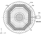
- FIG. 16 is a horizontal cross-sectional view of FIG. 15 taken along XV-XV.
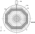
- FIG. 16 is a horizontal sectional view of FIG. 15 taken along XVI-XVI.
- FIG. 16 is a horizontal sectional view of FIG. 15 taken along XVII-XVII.
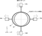
- 6 is a plan view showing a deformation pattern of a parison cross section by the parison thickness adjusting apparatus according to Embodiment 1.
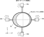
- FIG. 6 is a plan view showing a deformation pattern of a parison cross section by the parison thickness adjusting apparatus according to Embodiment 1.
- FIG. 6 is a plan view showing a deformation pattern of a parison cross section by the parison thickness adjusting apparatus according to Embodiment 1.
- FIG. 6 is a plan view showing a deformation pattern of a parison cross section by the parison thickness adjusting apparatus according to Embodiment 1.
- FIG. 6 is a plan view showing a deformation pattern of a parison cross section by the parison thickness adjusting apparatus according to Embodiment 1.
- FIG. 6 is a plan view showing a deformation pattern of a parison cross section by the parison thickness adjusting apparatus according to Embodiment 1.
- FIG. 6 is a horizontal sectional view of a parison thickness adjusting device 30 according to Embodiment 2.
- FIG. 6 is a horizontal sectional view of a parison thickness adjusting device 30 according to Embodiment 2.
- FIG. 6 is a plan view showing a deformation pattern of a parison cross section by the parison thickness adjusting apparatus according to Embodiment 1.
- FIG. 6 is a horizontal sectional view of a parison thickness adjusting device 30 according to Embodiment 2.
- FIG. 6 is a horizontal sectional view of a parison thickness adjusting device 30 according to Embodiment 2.
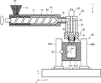
- FIGS. 1 to 3 are schematic cross-sectional views showing an outline of a hollow molding machine and a method for manufacturing a hollow molded article according to Embodiment 1.
- FIG. 1 The hollow molding machine according to Embodiment 1 is an extrusion blow molding machine for extruding a parison. Note that the right-handed xyz coordinates shown in FIG. 1 are convenient for explaining the positional relationship between the components. Usually, the xy plane is a horizontal plane, and the z-axis plus direction is vertically upward.
- the hollow molding machine 1 according to Embodiment 1 includes an extruder 10, a head 20, a parison thickness adjusting device 30, and a mold clamping machine 40.
- the thickness of the parison cross section is sequentially determined according to the shape of the hollow molded product to be manufactured. Can be adjusted. Therefore, it is possible to reduce the weight of the hollow molded product and reduce the weight. Therefore, the hollow molding machine according to the first embodiment is suitable for use in manufacturing a plastic fuel tank (PFT: Plastic-Fuel-Tank) for a vehicle that is particularly required to be reduced in weight as a hollow molded product.
- PFT Plastic-Fuel-Tank
- the extruder 10 is a screw type extruder, and a screw 12 extended in the x-axis direction is accommodated in a cylinder 11 extended in the x-axis direction.
- a hopper 13 for introducing the resin pellets 51 as the raw material of the parison 53 is provided on the upper side of the end of the cylinder 11 on the x-axis minus side.
- the resin pellets 51 supplied from the hopper 13 are pushed out from the root portion of the rotating screw 12 toward the tip portion, that is, in the x-axis plus direction.
- the resin pellet 51 is compressed by the screw 12 rotating inside the cylinder 11 and is changed into a molten resin 52.
- a motor is connected to the screw 12 as a drive source via a speed reducer, for example.
- the head 20 is connected to the extruder 10 via an adapter 14 provided at the x-axis plus side end of the extruder 10.
- the head body 21 is a cylindrical casing that extends in the vertical direction (z-axis direction), and is connected to the extruder 10 on the side surface of the upper end (z-axis plus side end).
- a discharge amount adjusting device 22 that adjusts the discharge amount of the molten resin 52 by moving a core 32 of a parison thickness adjusting device 30 described later up and down is provided.
- the head body 21 accommodates a spindle 23 extending in the vertical direction (z-axis direction) so as to connect the discharge amount adjusting device 22 and the core 32 of the parison thickness adjusting device 30.
- a parison thickness adjusting device 30 is installed at the lower end (z-axis minus side end) of the head main body 21.
- the parison thickness adjusting device 30 includes a substantially cylindrical die 31 having a frustoconical through hole, a substantially frustoconical core 32 inserted into the through hole of the die 31, and an inner peripheral surface of a tip portion of the die 31.
- a flexible ring 33 is provided.
- a gap between the die 31 and the core 32 is a resin flow path.
- the molten resin 52 that has passed through the resin flow path is formed into a cylindrical shape and is extruded as a parison 53 from the discharge port.
- the discharge port is defined by the flexible ring 33 and the core 32. That is, the cross-sectional shape of the parison 53 is defined by the flexible ring 33 and the core 32.
- the core 32 is moved up and down by the discharge amount adjusting device 22, the diameter of the core 32 at the discharge port changes. Therefore, the interval between the flexible ring 33 and the core 32, that is, the thickness of the cross section of the parison 53 changes. This change in thickness is a change in the longitudinal direction of the parison 53.
- the wall thickness of the cross section of the cylindrical parison 53 can be changed in the circumferential direction by deforming the flexible ring 33 into various shapes by a plurality of deformation actuators (not shown in FIGS. 1 to 3). it can.
- the parison 53 is extrusion-molded while sequentially adjusting the thickness of the parison cross section according to the shape of the hollow molded product to be manufactured. With such a configuration, it is possible to reduce the weight of the hollow molded product to be manufactured and reduce the weight.
- the details of the parison thickness adjusting device 30 will be described later.
- the molten resin 52 extruded in the x-axis plus direction from the extruder 10 changes the flow direction in the head 20 downward in the vertical direction (z-axis minus direction), and from the parison thickness adjusting device 30. Extruded as a parison 53.
- the mold clamping machine 40 includes a pair of molds 41a and 41b and a pair of movable plates 42a and 42b.
- the molds 41a and 41b are fixed to the movable plates 42a and 42b, respectively.
- the molds 41a and 41b open and close. 1 and 3 show a state where the molds 41a and 41b are opened, and FIG. 2 shows a state where the molds 41a and 41b are closed.
- the parison 53 is pushed out by a predetermined amount vertically downward (z-axis minus direction) with the molds 41a and 41b opened. Thereafter, as shown in FIG. 2, the parison 53 pushed out from the parison thickness adjusting device 30 in FIG. 1 is sandwiched between a pair of molds 41 a and 41 b, and cooling air is blown into the sandwiched parison 53.
- a hollow molded article 54 is manufactured.
- gas for example, cooling air
- the molds 41a and 41b move in the y-axis minus direction, and the extrusion of the parison 53 is continued. It should be noted that the extrusion of the parison 53 may be stopped without moving in the negative y-axis direction when the molds 41a and 41b are closed. Then, as shown in FIG. 3, after the molds 41a and 41b are opened and the hollow molded product 54 is taken out, the molds 41a and 41b move in the positive direction of the y axis and return to their original positions.
- the hollow molded product 54 is, for example, the above-described plastic fuel tank for vehicles.
- the hollow molded article 54 shown in FIG. 3 is simplified.
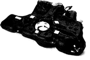
- FIG. 4 is an external view photograph of a plastic fuel tank for a vehicle.
- An actual plastic fuel tank has a large number of irregularities and has a complicated shape that tends to cause sagging.
- FIG. 5 is a plan view of the parison thickness adjusting apparatus according to the first comparative example.
- FIG. 5 shows only the core 32, the flexible ring 33, and the deformation actuators 34a and 34b, and the die 31 shown in FIGS. 1 to 3 is omitted. Note that the right-handed xyz coordinates shown in FIG. 5 coincide with those in FIG.
- two deformation actuators 34 a and 34 b are connected to the outer peripheral surface of the circular flexible ring 33.
- the deformation actuators 34a and 34b are provided on a straight line passing through the center of the flexible ring 33 (a center line extending in the x-axis direction indicated by a one-dot chain line in the example of FIG. 5).
- the deformation actuators 34a and 34b are arranged to face each other via the flexible ring 33, and each of them can be independently deformed by pushing and pulling the flexible ring 33 in the x-axis direction.
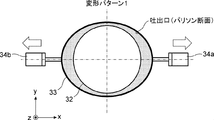
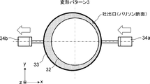
- FIGS. 6 to 8 are plan views showing deformation patterns 1 to 3 of the parison cross section by the parison thickness adjusting apparatus according to the comparative example 1, respectively.
- the thickness of the parison cross section is maximized at a portion where the deformation actuators 34a and 34b are connected to the flexible ring 33 (portion on the center line parallel to the x axis).
- the thickness of the parison cross section is minimized at a portion (a portion on a center line parallel to the y-axis) where the deformation actuators 34a and 34b are located between the portions connected to the flexible ring 33.
- the thickness of the parison cross section is minimized at a portion where the deformation actuators 34a and 34b are connected to the flexible ring 33 (portion on the center line parallel to the x axis).
- the thickness of the parison cross section is maximized at a portion (a portion on the center line parallel to the y axis) located in the middle of the portions where the deformation actuators 34a and 34b are connected to the flexible ring 33.
- the deformation actuator 34 a pushes the flexible ring 33, and the deformation actuator 34 b pulls the flexible ring 33.
- the flexible ring 33 remains circular but the center moves to the minus side in the x-axis direction, that is, decenters. . Therefore, the thickness of the parison cross section is minimized at a portion where the deformation actuator 34a is connected to the flexible ring 33 (a portion on the positive side in the x-axis direction on the center line parallel to the x-axis).
- the thickness of the parison cross section is maximized at a portion where the deformation actuator 34b is connected to the flexible ring 33 (a portion on the minus side in the x-axis direction on the center line parallel to the x-axis).
- the flexible ring 33 is eccentric and deforms into an ellipse that expands in the y-axis direction. If the amount pushed by the deformation actuator 34a is smaller than the amount pulled by the deformation actuator 34b, the flexible ring 33 is eccentric and deformed into an ellipse expanded in the x-axis direction. Further, when the deformation actuator 34 a pulls the flexible ring 33 and the deformation actuator 34 b pushes the flexible ring 33, a similar deformation pattern is obtained.
- the flexible ring 33 is deformed only by the two deformation actuators 34a and 34b. Therefore, there are few deformation patterns of a parison cross section, and it is difficult to make a parison cross section close to an ideal shape. Therefore, there is a problem that the effect of reducing the weight of the hollow molded product and reducing the weight is insufficient.
- FIG. 9 is a plan view of a parison thickness adjusting apparatus according to Comparative Example 2.
- FIG. 9 shows only the core 32, the flexible ring 33, and the deformation actuators 34a, 34b, 34c, and 34d, and the die 31 shown in FIGS. 1 to 3 is omitted. Note that the right-handed xyz coordinates shown in FIG. 9 coincide with those in FIG.
- the deformation actuators 34a and 34b are on the center line of the flexible ring 33 (in the example of FIG. 9, the center line extending in the x-axis direction indicated by the one-dot chain line). Is provided.
- the deformation actuators 34a and 34b are arranged to face each other via the flexible ring 33, and each of them can be independently deformed by pushing and pulling the flexible ring 33 in the x-axis direction.
- the deformation actuators 34c and 34d are flexible rings orthogonal to the center line of the flexible ring 33 provided with the deformation actuators 34a and 34b (in the example of FIG. 9, the center line extending in the x-axis direction indicated by a one-dot chain line). 33 center lines (in the example of FIG. 9, center lines extending in the y-axis direction indicated by a one-dot chain line).
- the deformation actuators 34c and 34d are arranged to face each other via the flexible ring 33, and each of them can be independently deformed by pushing and pulling the flexible ring 33 in the y-axis direction.
- FIG. 10 are plan views showing deformation patterns 1, 2, 4, and 5 of the parison section by the parison thickness adjusting apparatus according to Comparative Example 2, respectively.
- the deformation pattern 1 shown in FIG. 10 is the same deformation pattern as the deformation pattern 1 of the comparative example 1 shown in FIG.
- the deformation actuators 34 a and 34 b both pull the flexible ring 33
- the deformation actuators 34 c and 34 d both push the flexible ring 33. Therefore, the flexible ring 33 having a circular shape is enlarged in the x-axis direction and deformed into an ellipse reduced in the y-axis direction. Therefore, the wall thickness of the parison cross section is maximized at a portion where the deformation actuators 34a and 34b are connected to the flexible ring 33 (portion on the center line parallel to the x axis). On the other hand, the thickness of the parison cross section is minimized at the portion where the deformation actuators 34c and 34d are connected to the flexible ring 33 (the portion on the center line parallel to the y axis).
- the deformation pattern 2 shown in FIG. 11 is the same deformation pattern as the deformation pattern 2 of the comparative example 1 shown in FIG.
- the deformation actuators 34 a and 34 b both push the flexible ring 33
- the deformation actuators 34 c and 34 d both pull the flexible ring 33. Therefore, the flexible ring 33 having a circular shape is reduced in the x-axis direction and deformed into an ellipse enlarged in the y-axis direction. Therefore, the wall thickness of the parison cross section is minimized at a portion where the deformation actuators 34a and 34b are connected to the flexible ring 33 (portion on the center line parallel to the x axis). On the other hand, the thickness of the parison cross section is maximized at a portion where the deformation actuators 34c and 34d are connected to the flexible ring 33 (portion on the center line parallel to the y axis).
- the deformation pattern 4 shown in FIG. 12 is a new deformation pattern that does not exist in the first comparative example.
- the four deformation actuators 34 a, 34 b, 34 c, 34 d all press the flexible ring 33. Therefore, the flexible ring 33 having a circular shape is reduced in the x-axis direction and the y-axis direction and deformed into a quadrangular shape. Accordingly, a portion where the deformation actuators 34a, 34b are connected to the flexible ring 33 (portion on the center line parallel to the x axis) and a portion where the deformation actuators 34c, 34d are connected to the flexible ring 33 (parallel to the y axis).
- the thickness of the cross section of the parison is minimized.
- the part located in the middle of the parts where the deformation actuators 34a, 34b, 34c, 34d are connected to the flexible ring 33 parts on the two center lines intersecting the center line parallel to the x axis at 45 °
- the wall thickness of the parison cross section becomes maximum.
- the deformation pattern 5 shown in FIG. 13 is also a new deformation pattern not found in Comparative Example 1.
- the four deformation actuators 34 a, 34 b, 34 c, 34 d all pull the flexible ring 33. Therefore, the flexible ring 33 having a circular shape expands in the x-axis direction and the y-axis direction and is deformed into a quadrangular shape. Accordingly, a portion where the deformation actuators 34a, 34b are connected to the flexible ring 33 (portion on the center line parallel to the x axis) and a portion where the deformation actuators 34c, 34d are connected to the flexible ring 33 (parallel to the y axis).
- the thickness of the cross section of the parison becomes maximum.
- the part located in the middle of the parts where the deformation actuators 34a, 34b, 34c, 34d are connected to the flexible ring 33 parts on the two center lines intersecting the center line parallel to the x axis at 45 °. The wall thickness of the parison cross section is minimized.
- FIG. 14 is a plan view showing a deformation pattern of the comparative example 2 corresponding to the deformation pattern 3 of the comparative example 1.
- FIG. 14 similarly to the deformation pattern 3 of Comparative Example 1 shown in FIG. 8, the deformation actuator 34 a pushes the flexible ring 33, and the deformation actuator 34 b pulls the flexible ring 33.
- the flexible ring 33 is decentered to the minus side in the x-axis direction.
- the flexible ring 33 is constrained by the deformation actuators 34c and 34d. Can not do it.
- the flexible ring 33 is deformed by the four deformation actuators 34a, 34b, 34c, and 34d. Therefore, there are more deformation patterns of a parison cross section than Comparative Example 1, and the parison cross section is easily brought close to an ideal shape. As a result, it is possible to reduce the weight of the hollow molded article from the comparative example 1 and reduce the weight. On the other hand, the eccentricity of the flexible ring 33 that was possible in Comparative Example 1 is not possible. For this reason, depending on the ideal shape of the parison cross section, it is possible that the hollowness of the hollow molded product is increased as compared with Comparative Example 1. Such a problem may occur if there are three or more deformation actuators.
- FIG. 15 is a vertical sectional view of the parison thickness adjusting apparatus 30 according to the first embodiment.
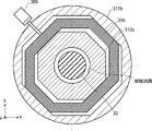
- 16 is a horizontal cross-sectional view taken along the line XV-XV in FIG. 17 is a horizontal sectional view taken along the line XVI-XVI of FIG. 18 is a horizontal sectional view taken along line XVII-XVII in FIG.
- the right-handed xyz coordinates shown in FIGS. 15 to 18 are the same as those in FIG.
- the parison thickness adjusting device 30 includes a substantially cylindrical die 31 having a substantially truncated cone-shaped through hole, and a substantially truncated cone shape inserted into the through hole of the die 31.
- Core 32 and flexible ring 33 provided on the inner peripheral surface of the tip of die 31.
- a gap between the die 31 and the core 32 is a resin flow path.
- a discharge port is defined by the core 32 and the flexible ring 33.
- the thickness of the parison 53 changes. This change in thickness is a change in the longitudinal direction of the parison 53.
- the thickness of the parison cross section increases when the core 32 moves downward (z axis minus direction), and the thickness of the parison cross section decreases when it moves upward (z axis plus direction).
- the thickness of the parison cross section can be changed in the circumferential direction by deforming the flexible ring 33 into various shapes by the four deformation actuators 34a, 34b, 34c, and 34d. .
- the flexible ring 33 can be eccentric with respect to the core 32 by the configuration described in detail below.
- the parison 53 is extrusion-molded while sequentially adjusting the thickness of the parison cross section according to the shape of the hollow molded product to be manufactured. With such a configuration, it is possible to reduce the weight of the hollow molded product to be manufactured and reduce the weight.
- the die 31 includes a fixed die 311 provided at an upper portion, a movable die 312 slidably provided on the lower surface of the fixed die 311, and a die holder 313 that slidably supports the movable die 312. It has three different members.
- the fixed die 311 is a substantially cylindrical block having a substantially frustoconical through hole whose diameter decreases toward the lower side (minus side in the z-axis direction), and is fixed to the head main body 21 shown in FIG. Yes.
- the movable die 312 is a substantially cylindrical block having a substantially columnar through-hole, and a flexible ring 33 is attached to the inner peripheral surface.
- the part inserted into the through hole of the movable die 312 is formed in a substantially cylindrical shape.
- the discharge port is defined by the tip of the core 32 and the tip of the flexible ring 33. Note that the inner diameter of the movable die 312 is pruned so as to increase on the discharge port side.
- the movable die 312 has an upper flange portion 312b on the upper side (z-axis direction plus side) of the cylindrical main body portion 312a, and on the lower side (z-axis direction minus side) of the body portion 312a.
- a lower flange portion 312c is provided.
- the upper flange portion 312 b is a sliding portion in the movable die 312.
- the upper surface of the upper flange portion 312b is slidably in contact with the lower surface of the fixed die 311. Further, the lower surface of the upper flange portion 312b is slidably supported by the die holder 313.
- boundary line between the main body portion 312a and the upper flange portion 312b and the boundary line between the main body portion 312a and the lower flange portion 312c which are indicated by a two-dot chain line in FIG. 15, are for convenience of explanation.
- the upper flange portion 312b of the movable die 312 has an annular structure having a regular octagonal outer periphery and a circular inner periphery in plan view.
- the upper flange portion 312b is moved in the x-axis direction by an eccentric actuator (for example, a first eccentric actuator) 36a via an eccentric ring (for example, a first eccentric ring) 35a. be able to.
- the upper flange portion 312b is moved in the y-axis direction by an eccentric actuator (for example, a second eccentric actuator) 36b via an eccentric ring (for example, a second eccentric ring) 35b.
- an eccentric actuator for example, a second eccentric actuator
- the movable die 312 and the flexible ring 33 attached to the movable die 312 can be eccentric with respect to the core 32 in a free direction on the xy plane. Details of the eccentric rings 35a and 35b will be described later.
- eccentric actuators 36a and 36b may be provided so that the flexible ring 33 can be eccentric in only one direction.
- the eccentric actuator can be directly connected to the upper flange portion 312b without using the eccentric ring.
- the lower flange portion 312c of the movable die 312 has an annular structure in plan view.
- the rods of four deformation actuators 34a, 34b, 34c, and 34d connected to the flexible ring 33 are inserted into the lower flange portion 312c. That is, in the lower flange portion 312c, four through holes for inserting the rods of the deformation actuators 34a, 34b, 34c, 34d are formed radially from the inner peripheral surface to the outer peripheral surface at 90 ° intervals, that is, at equal intervals.
- the four deformation actuators 34 a, 34 b, 34 c, 34 d connected to the flexible ring 33 are mounted on the movable die 312 and can move together with the movable die 312 and the flexible ring 33.
- the deformation actuators 34a and 34b are provided on the center line of the flexible ring 33 (in the example of FIG. 18, the center line extending in the x-axis direction indicated by the one-dot chain line).
- the deformation actuators 34a and 34b are arranged to face each other via the flexible ring 33, and each of them can be independently deformed by pushing and pulling the flexible ring 33 in the x-axis direction.
- the deformation actuators 34c and 34d are flexible rings orthogonal to the center line of the flexible ring 33 provided with the deformation actuators 34a and 34b (in the example of FIG. 18, the center line extending in the x-axis direction indicated by a one-dot chain line). 33 center lines (in the example of FIG. 18, center lines extending in the y-axis direction indicated by a one-dot chain line).
- the deformation actuators 34c and 34d are arranged to face each other via the flexible ring 33, and each of them can be independently deformed by pushing and pulling the flexible ring 33 in the y-axis direction.
- the four deformation actuators 34a, 34b, 34c, and 34d provide a discharge port (that is, a parison cross section) that is a gap between the flexible ring 33 and the core 32. Can be deformed.
- the number of deformation actuators may be three or more.
- the die holder 313 is a frame having a side wall portion 313 b that rises in the z-axis plus direction along the outer peripheral edge of the bottom surface portion 313 a, and is fixed to the lower surface of the fixed die 311.
- the die holder 313 is an L-shaped frame in a vertical section as shown in FIG. 15, and an annular frame in a horizontal section as shown in FIGS.
- the inner peripheral surface of the side wall portion 313b is formed in a regular octagonal shape.
- a rod of an eccentric actuator 36a connected to the eccentric ring 35a is inserted through the side wall 313b. That is, a through hole for inserting the rod of the eccentric actuator 36a is formed in the side wall 313b in the x-axis direction from the inner peripheral surface toward the outer peripheral surface.
- a rod of an eccentric actuator 36b connected to the eccentric ring 35b is inserted through the side wall 313b. That is, a through hole for inserting the rod of the eccentric actuator 36b is formed in the side wall 313b in the y-axis direction from the inner peripheral surface toward the outer peripheral surface. Note that the boundary line between the bottom surface portion 313a and the side wall portion 313b indicated by a two-dot chain line in FIG. 15 is for convenience of explanation.
- the eccentric ring 35a is an octagonal ring extending in the y-axis direction. Specifically, of the eight sides constituting the outer periphery of the eccentric ring 35a, two sides parallel to the x axis are shorter than the sides constituting the inner circumference of the regular octagonal side wall portion 313b, and the other six sides. Is the same length as the side constituting the inner periphery of the side wall 313b.
- the outer peripheral surface of the eccentric ring 35a is in contact with the inner peripheral surface of the side wall portion 313b on two surfaces parallel to the x axis, and is separated from the inner peripheral surface of the side wall portion 313b on the other six surfaces. Accordingly, the eccentric ring 35a can move only in the x-axis direction inside the regular octagonal side wall portion 313b.
- the inner peripheral surface of the eccentric ring 35a is in contact with the outer peripheral surface of the upper flange portion 312b on two surfaces parallel to the y-axis, and is separated from the outer peripheral surface of the upper flange portion 312b on the other six surfaces.
- the upper flange portion 312b is also moved together. Further, the upper flange portion 312b can move only in the y-axis direction within the eccentric ring 35a.
- the eccentric ring 35b is an octagonal ring extending in the x-axis direction. Specifically, of the eight sides constituting the outer periphery of the eccentric ring 35b, two sides parallel to the y-axis are shorter than the sides constituting the inner circumference of the regular octagonal side wall portion 313b, and the other six sides. Is the same length as the side constituting the inner periphery of the side wall 313b. Therefore, the outer peripheral surface of the eccentric ring 35b is in contact with the inner peripheral surface of the side wall portion 313b on two surfaces parallel to the y-axis, and is separated from the inner peripheral surface of the side wall portion 313b on the other six surfaces. Therefore, the eccentric ring 35b can move in the x-axis direction inside the regular octagonal side wall portion 313b.
- the inner peripheral surface of the eccentric ring 35b is in contact with the outer peripheral surface of the upper flange portion 312b on two surfaces parallel to the x-axis, and is separated from the outer peripheral surface of the upper flange portion 312b on the other six surfaces.
- the upper flange portion 312b is also moved together. Further, the upper flange portion 312b can move in the x-axis direction inside the eccentric ring 35b.
- the upper flange portion 312b that is, the movable die 312 can be moved in a free direction on the xy plane by the eccentric rings 35a and 35b. Accordingly, the flexible ring 33 attached to the movable die 312 can be decentered with respect to the core 32 together with the four deformation actuators 34a, 34b, 34c, 34d.
- the eccentric ring 35a is mounted on the eccentric ring 35b, but the vertical relationship between the two may be reversed.
- the shape of the eccentric ring 35b is not limited to an octagon, and may be a shape having two pairs of parallel sides orthogonal to each other, such as a quadrangle and a hexagon.
- the discharge port that is, the parison cross section
- the flexible ring 33 can be eccentric with respect to the core 32.
- FIGS. 19 to 23 a typical example of the deformation pattern of the parison cross section by the parison thickness adjusting apparatus according to the first embodiment will be described.
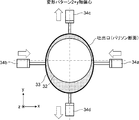
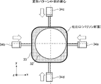
- 19 to 23 are plan views showing deformation patterns of the parison section by the parison thickness adjusting apparatus according to the first embodiment.
- the deformation pattern shown in FIG. 19 is a deformation pattern in which the deformation pattern 1 of Comparative Example 2 shown in FIG. 10 is combined with the eccentricity in the x-axis direction.
- the deformation actuators 34 a and 34 b both pull the flexible ring 33
- the deformation actuators 34 c and 34 d both push the flexible ring 33. Therefore, the flexible ring 33 having a circular shape is enlarged in the x-axis direction and deformed into an ellipse reduced in the y-axis direction.
- the flexible ring 33 is eccentric in the x-axis minus direction.
- the deformation actuators 34 a and 34 b both push the flexible ring 33, and the deformation actuators 34 c and 34 d both pull the flexible ring 33. Therefore, the flexible ring 33 having a circular shape is reduced in the x-axis direction and deformed into an ellipse enlarged in the y-axis direction. At the same time, the flexible ring 33 is eccentric in the y-axis minus direction.
- Comparative Example 1 it was possible to decenter only in the x-axis direction, but not in the y-axis direction or oblique direction. Further, in Comparative Example 2, it could not be decentered.
- the parison thickness adjusting apparatus according to the first embodiment it can be decentered in a free direction on the xy plane.
- the deformation pattern shown in FIG. 21 is the same deformation pattern as the deformation pattern 3 of Comparative Example 1 shown in FIG.
- the flexible ring 33 is eccentric in the minus direction of the x-axis in a state where none of the four deformation actuators 34a, 34b, 34c, 34d pushes or pulls the flexible ring 33. .
- the flexible ring 33 is eccentric in the oblique direction of the x-axis minus direction and the y-axis minus direction.
- the flexible ring 33 is a deformation pattern in which the deformation pattern 5 shown in FIG. 13 and the eccentricity in the x-axis direction are combined.
- the four deformation actuators 34a, 34b, 34c, and 34d all pull the flexible ring 33. Therefore, the flexible ring 33 having a circular shape expands in the x-axis direction and the y-axis direction and is deformed into a quadrangular shape. At the same time, the flexible ring 33 is eccentric in the x-axis minus direction.
- the possible parison cross section deformation patterns are remarkably increased. Can be brought close to the ideal shape.
- the parison thickness adjusting device according to Comparative Example 1 or Comparative Example 2 it is possible to reduce the waste of the hollow molded product more and reduce the weight.
- Embodiment 2 Next, a hollow molding machine according to Embodiment 2 will be described.
- the overall configuration of the hollow molding machine according to Embodiment 2 is the same as the overall configuration of the hollow molding machine according to Embodiment 1 shown in FIGS.
- the hollow molding machine according to the second embodiment is different from the hollow molding machine according to the first embodiment in the configuration of the parison thickness adjusting device.
- 24 and 25 are horizontal sectional views of the parison thickness adjusting device 30 according to the second embodiment. 24 and 25 correspond to FIGS. 16 and 17, respectively. Note that the right-handed xyz coordinates shown in FIGS. 24 and 25 coincide with those in FIG.
- the eccentric actuator 36a is arranged at a position corresponding to the deformation actuator 34a in plan view.
- the eccentric actuator 36b is disposed at a position corresponding to the deformation actuator 34c in plan view.
- the eccentric actuators 36a and 36b move from the x axis to the y axis around the central axis of the core 32 with respect to the deformation actuators 34a and 34c, respectively. It is arrange
- the eccentric actuators 36a and 36b and the deformation actuators 34a and 34c are arranged at corresponding positions in plan view. For this reason, it is necessary to secure a distance in the height direction between the eccentric actuators 36a and 36b and the deformation actuators 34a and 34c, and the apparatus becomes large in the height direction.
- the parison thickness adjusting apparatus 30 according to the second embodiment can be smaller and lighter than the parison thickness adjusting apparatus 30 according to the first embodiment.
Landscapes
- Engineering & Computer Science (AREA)
- Manufacturing & Machinery (AREA)
- Mechanical Engineering (AREA)
- Blow-Moulding Or Thermoforming Of Plastics Or The Like (AREA)
Abstract
一実施の形態に係るパリソン肉厚調整装置(30)は、中空成形機等に好適であり、フレキシブルリング(33)が取り付けられた可動ダイ(312)にフレキシブルリング(33)を変形させる少なくとも3つの変形用アクチュエータ(34a、34b、34c、34d)が搭載されており、当該可動ダイ(312)に連結された第1の偏心用アクチュエータ(36a)によって、可動ダイ(312)をコア(32)に対して第1の方向に偏心させる。
Description
本発明はパリソン肉厚調整装置、それを備えた中空成形機、及び中空成形品の製造方法に関する。
中空成形機(ブロー成形機)では、押出機に連結されたヘッドから押し出された筒状のパリソンを一対の金型で挟み込み、金型内のパリソン内部にエアを吹き込むことにより中空成形品を製造する。このような中空成形機において、ヘッドの先端部に、パリソン断面の肉厚を円周方向において変化させることができるパリソン肉厚調整装置を設けたものが知られている。製造する中空成形品の形状に応じて、パリソン断面の肉厚を逐次調整することにより、中空成形品の駄肉を削減し、軽量化することができる。
特許文献1では、パリソンの外周面を規定するフレキシブルリングを複数のアクチュエータによって様々な形状に変形させることにより、パリソン断面の肉厚を円周方向において変化させている。
特許文献2では、パリソンの外周面を規定するダイをアクチュエータによって偏心させることにより、パリソン断面の肉厚を円周方向において変化させている。
特許文献2では、パリソンの外周面を規定するダイをアクチュエータによって偏心させることにより、パリソン断面の肉厚を円周方向において変化させている。
発明者は、パリソン断面の肉厚を円周方向において変化させることができるパリソン肉厚調整装置の開発に際し、様々な課題を見出した。
その他の課題と新規な特徴は、本明細書の記述及び添付図面から明らかになるであろう。
その他の課題と新規な特徴は、本明細書の記述及び添付図面から明らかになるであろう。
一実施の形態に係るパリソン肉厚調整装置では、フレキシブルリングが取り付けられた可動ダイにフレキシブルリングを変形させる少なくとも3つの変形用アクチュエータが搭載されており、当該可動ダイに連結された第1の偏心用アクチュエータによって、可動ダイをコアに対して第1の方向に偏心させる。
前記一実施の形態によれば、例えば中空成形機等に好適であって、良質なパリソン肉厚調整装置を提供することができる。
以下、具体的な実施の形態について、図面を参照しながら詳細に説明する。ただし、以下の実施の形態に限定される訳ではない。また、説明を明確にするため、以下の記載及び図面は、適宜簡略化されている。
(実施の形態1)
<中空成形機の全体構成>
まず、図1~3を参照して、実施の形態1に係る中空成形機の全体構成について説明する。図1~3は、実施の形態1に係る中空成形機及び中空成形品の製造方法の概要を示す模式的断面図である。実施の形態1に係る中空成形機は、パリソンを押出成形する押出ブロー成形機である。
なお、図1に示した右手系xyz座標は、構成要素の位置関係を説明するための便宜的なものである。通常、xy平面が水平面であって、z軸プラス向きが鉛直上向きとなる。
<中空成形機の全体構成>
まず、図1~3を参照して、実施の形態1に係る中空成形機の全体構成について説明する。図1~3は、実施の形態1に係る中空成形機及び中空成形品の製造方法の概要を示す模式的断面図である。実施の形態1に係る中空成形機は、パリソンを押出成形する押出ブロー成形機である。
なお、図1に示した右手系xyz座標は、構成要素の位置関係を説明するための便宜的なものである。通常、xy平面が水平面であって、z軸プラス向きが鉛直上向きとなる。
図1に示すように、実施の形態1に係る中空成形機1は、押出機10、ヘッド20、パリソン肉厚調整装置30、型締機40を備えている。詳細には後述するように、実施の形態1に係る中空成形機は、パリソン肉厚調整装置30を有しているため、製造する中空成形品の形状に応じて、パリソン断面の肉厚を逐次調整することができる。そのため、中空成形品の駄肉を削減し、軽量化することができる。従って、実施の形態1に係る中空成形機は、軽量化が特に要求される車両用のプラスチック燃料タンク(PFT:Plastic Fuel Tank)を中空成形品として製造する用途に好適である。
押出機10はスクリュー式押出機であって、x軸方向に延設されたシリンダ11の内部にx軸方向に延設されたスクリュー12が収容されている。シリンダ11のx軸マイナス側端部の上側に、パリソン53の原料である樹脂ペレット51を投入するためのホッパ13が設けられている。ホッパ13から供給された樹脂ペレット51は、回転するスクリュー12の根元部から先端部に向かって、すなわちx軸プラス方向に押し出される。樹脂ペレット51は、シリンダ11の内部において回転するスクリュー12によって圧縮され、溶融樹脂52に変化する。
なお、図示しないが、スクリュー12には、例えば、減速機を介してモータが駆動源として連結される。
なお、図示しないが、スクリュー12には、例えば、減速機を介してモータが駆動源として連結される。
ヘッド20は、押出機10のx軸プラス側端部に設けられたアダプタ14を介して、押出機10に連結されている。ヘッド本体21は、鉛直方向(z軸方向)に延設された円筒状の筐体であり、上端部(z軸プラス側端部)の側面において押出機10に連結されている。ヘッド本体21の上側には、後述するパリソン肉厚調整装置30のコア32を上下動させ、溶融樹脂52の吐出量を調整する吐出量調整装置22が設けられている。ヘッド本体21の内部には、吐出量調整装置22とパリソン肉厚調整装置30のコア32とを連結するように鉛直方向(z軸方向)に延設されたスピンドル23が収容されている。そして、ヘッド本体21の下端部(z軸マイナス側端部)には、パリソン肉厚調整装置30が設置されている。
パリソン肉厚調整装置30は、円錐台状の貫通孔を有する略円柱状のダイ31、ダイ31の貫通孔に挿入される略円錐台状のコア32、及びダイ31の先端部の内周面に設けられたフレキシブルリング33を備えている。ダイ31とコア32との隙間が樹脂流路である。当該樹脂流路を通過した溶融樹脂52が筒状に成形されて、吐出口からパリソン53として押し出される。
ここで、フレキシブルリング33とコア32とにより吐出口が規定される。すなわち、パリソン53の断面形状は、フレキシブルリング33と、コア32とによって規定される。吐出量調整装置22によりコア32を上下動させると、吐出口におけるコア32の径が変化する。そのため、フレキシブルリング33とコア32との間隔すなわちパリソン53の断面の肉厚が変化する。この肉厚の変化は、パリソン53の長手方向における変化である。
さらに、フレキシブルリング33を複数の変形用アクチュエータ(図1~3においては不図示)によって様々な形状に変形させることにより、筒状のパリソン53の断面の肉厚を円周方向において変化させることができる。
このように、製造する中空成形品の形状に応じて、パリソン断面の肉厚を逐次調整ながらパリソン53を押出成形する。このような構成により、製造する中空成形品の駄肉を削減し、軽量化することができる。
なお、パリソン肉厚調整装置30の詳細については後述する。
このように、製造する中空成形品の形状に応じて、パリソン断面の肉厚を逐次調整ながらパリソン53を押出成形する。このような構成により、製造する中空成形品の駄肉を削減し、軽量化することができる。
なお、パリソン肉厚調整装置30の詳細については後述する。
図1に示すように、押出機10からx軸プラス方向に押し出された溶融樹脂52は、ヘッド20において鉛直方向下向き(z軸マイナス方向)に流動方向を変化させ、パリソン肉厚調整装置30からパリソン53として押し出される。
型締機40は、一対の金型41a、41b、及び一対の可動盤42a、42bを備えている。金型41a、41bは、それぞれ可動盤42a、42bに固定されている。可動盤42a、42bがx軸方向にスライドすることにより、金型41a、41bが開閉する。図1、図3は、金型41a、41bが開いた状態を示しており、図2は、金型41a、41bが閉まった状態を示している。
図1に示すように、中空成形機1では、金型41a、41bが開いた状態で、パリソン53が鉛直方向下向き(z軸マイナス方向)に所定量押し出される。
その後、図2に示すように、図1においてパリソン肉厚調整装置30から押し出されたパリソン53を一対の金型41a、41bで挟み込み、挟み込まれたパリソン53の内部に冷却エアを吹き込むことにより、中空成形品54が製造される。図の例では、金型41aに設けられた吹込針43からガス(例えば冷却エア)を吹き込む。図2に示すように、金型41a、41bが閉まった状態で、金型41a、41bがy軸マイナス方向に移動し、パリソン53の押し出しが継続される。なお、金型41a、41bが閉まった状態で、y軸マイナス方向に移動せず、パリソン53の押し出しを停止してもよい。
そして、図3に示すように、金型41a、41bが開き、中空成形品54が取り出された後、金型41a、41bがy軸プラス方向に移動して元の位置に戻る。
その後、図2に示すように、図1においてパリソン肉厚調整装置30から押し出されたパリソン53を一対の金型41a、41bで挟み込み、挟み込まれたパリソン53の内部に冷却エアを吹き込むことにより、中空成形品54が製造される。図の例では、金型41aに設けられた吹込針43からガス(例えば冷却エア)を吹き込む。図2に示すように、金型41a、41bが閉まった状態で、金型41a、41bがy軸マイナス方向に移動し、パリソン53の押し出しが継続される。なお、金型41a、41bが閉まった状態で、y軸マイナス方向に移動せず、パリソン53の押し出しを停止してもよい。
そして、図3に示すように、金型41a、41bが開き、中空成形品54が取り出された後、金型41a、41bがy軸プラス方向に移動して元の位置に戻る。
なお、中空成形品54は、例えば、上述の車両用のプラスチック燃料タンクである。図3に示した中空成形品54は単純化されている。図4は、車両用のプラスチック燃料タンクの外観写真である。実際のプラスチック燃料タンクは多数の凹凸を有し、駄肉が発生し易い複雑な形状を有している。
<比較例1に係るパリソン肉厚調整装置>
次に、図5を参照して、発明者が事前に検討した比較例1に係るパリソン肉厚調整装置について説明する。図5は、比較例1に係るパリソン肉厚調整装置の平面図である。図5には、コア32、フレキシブルリング33、変形用アクチュエータ34a、34bのみが示されており、図1~3において示されているダイ31は省略されている。なお、図5に示した右手系xyz座標は、図1と一致している。
次に、図5を参照して、発明者が事前に検討した比較例1に係るパリソン肉厚調整装置について説明する。図5は、比較例1に係るパリソン肉厚調整装置の平面図である。図5には、コア32、フレキシブルリング33、変形用アクチュエータ34a、34bのみが示されており、図1~3において示されているダイ31は省略されている。なお、図5に示した右手系xyz座標は、図1と一致している。
比較例1に係るパリソン肉厚調整装置では、円形のフレキシブルリング33の外周面に2つの変形用アクチュエータ34a、34bが連結されている。変形用アクチュエータ34a、34bは、フレキシブルリング33の中心を通過する直線(図5の例では、一点鎖線で示したx軸方向に延びた中心線)上に設けられている。変形用アクチュエータ34a、34bは、フレキシブルリング33を介して対向配置されており、それぞれが独立してフレキシブルリング33をx軸方向に押し引きして、変形させることができる。
このように、比較例1に係るパリソン肉厚調整装置では、2つの変形用アクチュエータ34a、34bによりフレキシブルリング33とコア32との隙間である吐出口(すなわちパリソン断面)を変形させることができる。
ここで、図6~図8は、それぞれ比較例1に係るパリソン肉厚調整装置によるパリソン断面の変形パターン1~3を示す平面図である。
ここで、図6~図8は、それぞれ比較例1に係るパリソン肉厚調整装置によるパリソン断面の変形パターン1~3を示す平面図である。
図6に示した変形パターン1では、変形用アクチュエータ34a、34bが共にフレキシブルリング33を引くため、円状であったフレキシブルリング33がx軸方向に拡大し、y軸方向に縮小した楕円状に変形している。そのため、変形用アクチュエータ34a、34bがフレキシブルリング33に連結された部位(x軸に平行な中心線上の部位)においてパリソン断面の肉厚が最大となる。一方、変形用アクチュエータ34a、34bがフレキシブルリング33に連結された部位同士の中間に位置する部位(y軸に平行な中心線上の部位)においてパリソン断面の肉厚が最小となる。
図7に示した変形パターン2では、変形用アクチュエータ34a、34bが共にフレキシブルリング33を押すため、円状であったフレキシブルリング33がx軸方向に縮小し、y軸方向に拡大した楕円状に変形している。そのため、変形用アクチュエータ34a、34bがフレキシブルリング33に連結された部位(x軸に平行な中心線上の部位)においてパリソン断面の肉厚が最小となる。一方、変形用アクチュエータ34a、34bがフレキシブルリング33に連結された部位同士の中間に位置する部位(y軸に平行な中心線上の部位)においてパリソン断面の肉厚が最大となる。
図8に示した変形パターン3では、変形用アクチュエータ34aがフレキシブルリング33を押し、変形用アクチュエータ34bがフレキシブルリング33を引く。図8の例では、変形用アクチュエータ34aが押す量と、変形用アクチュエータ34bが引く量とが等しいため、フレキシブルリング33は円状のままx軸方向マイナス側に中心が移動する、すなわち、偏心する。そのため、変形用アクチュエータ34aがフレキシブルリング33に連結された部位(x軸に平行な中心線上においてx軸方向プラス側の部位)においてパリソン断面の肉厚が最小となる。一方、変形用アクチュエータ34bがフレキシブルリング33に連結された部位(x軸に平行な中心線上においてx軸方向マイナス側の部位)においてパリソン断面の肉厚が最大となる。
なお、変形用アクチュエータ34aが押す量が、変形用アクチュエータ34bが引く量よりも大きければ、フレキシブルリング33は偏心すると共に、y軸方向に拡大した楕円状に変形する。変形用アクチュエータ34aが押す量が、変形用アクチュエータ34bが引く量よりも小さければ、フレキシブルリング33は偏心すると共に、x軸方向に拡大した楕円状に変形する。また、変形用アクチュエータ34aがフレキシブルリング33を引き、変形用アクチュエータ34bがフレキシブルリング33を押す場合も同様の変形パターンとなる。
比較例1に係るパリソン肉厚調整装置では、フレキシブルリング33を2つの変形用アクチュエータ34a、34bのみで変形させている。そのため、パリソン断面の変形パターンが少なく、パリソン断面を理想形状に近付けることが難しい。従って、中空成形品の駄肉を削減し、軽量化する効果が不充分であるという問題があった。
<比較例2に係るパリソン肉厚調整装置>
次に、図9を参照して、発明者が事前に検討した比較例2に係るパリソン肉厚調整装置について説明する。図9は、比較例2に係るパリソン肉厚調整装置の平面図である。図9には、コア32、フレキシブルリング33、変形用アクチュエータ34a、34b、34c、34dのみが示されており、図1~3において示されているダイ31は省略されている。なお、図9に示した右手系xyz座標は、図1と一致している。
次に、図9を参照して、発明者が事前に検討した比較例2に係るパリソン肉厚調整装置について説明する。図9は、比較例2に係るパリソン肉厚調整装置の平面図である。図9には、コア32、フレキシブルリング33、変形用アクチュエータ34a、34b、34c、34dのみが示されており、図1~3において示されているダイ31は省略されている。なお、図9に示した右手系xyz座標は、図1と一致している。
比較例2に係るパリソン肉厚調整装置では、円形のフレキシブルリング33の外周面に2つの変形用アクチュエータ34a、34bに加え、さらに2つの変形用アクチュエータ34c、34dが連結されている。
比較例1に係るパリソン肉厚調整装置と同様に、変形用アクチュエータ34a、34bは、フレキシブルリング33の中心線(図9の例では、一点鎖線で示したx軸方向に延びた中心線)上に設けられている。変形用アクチュエータ34a、34bは、フレキシブルリング33を介して対向配置されており、それぞれが独立してフレキシブルリング33をx軸方向に押し引きして、変形させることができる。
比較例1に係るパリソン肉厚調整装置と同様に、変形用アクチュエータ34a、34bは、フレキシブルリング33の中心線(図9の例では、一点鎖線で示したx軸方向に延びた中心線)上に設けられている。変形用アクチュエータ34a、34bは、フレキシブルリング33を介して対向配置されており、それぞれが独立してフレキシブルリング33をx軸方向に押し引きして、変形させることができる。
変形用アクチュエータ34c、34dは、変形用アクチュエータ34a、34bが設けられたフレキシブルリング33の中心線(図9の例では、一点鎖線で示したx軸方向に延びた中心線)と直交するフレキシブルリング33の中心線(図9の例では、一点鎖線で示したy軸方向に延びた中心線)上に設けられている。変形用アクチュエータ34c、34dは、フレキシブルリング33を介して対向配置されており、それぞれが独立してフレキシブルリング33をy軸方向に押し引きして、変形させることができる。
このように、比較例2に係るパリソン肉厚調整装置では、4つの変形用アクチュエータ34a、34b、34c、34dによりフレキシブルリング33とコア32との隙間である吐出口(すなわちパリソン断面)を変形させることができる。
ここで、図10、図11、図12、図13は、それぞれ比較例2に係るパリソン肉厚調整装置によるパリソン断面の変形パターン1、2、4、5を示す平面図である。
ここで、図10、図11、図12、図13は、それぞれ比較例2に係るパリソン肉厚調整装置によるパリソン断面の変形パターン1、2、4、5を示す平面図である。
図10に示した変形パターン1は、図6に示した比較例1の変形パターン1と同じ変形パターンである。比較例2では、図10に示すように、変形用アクチュエータ34a、34bがいずれもフレキシブルリング33を引くと共に、変形用アクチュエータ34c、34dがいずれもフレキシブルリング33を押す。そのため、円状であったフレキシブルリング33がx軸方向に拡大し、y軸方向に縮小した楕円状に変形している。従って、変形用アクチュエータ34a、34bがフレキシブルリング33に連結された部位(x軸に平行な中心線上の部位)においてパリソン断面の肉厚が最大となる。一方、変形用アクチュエータ34c、34dがフレキシブルリング33に連結された部位(y軸に平行な中心線上の部位)においてパリソン断面の肉厚が最小となる。
図11に示した変形パターン2は、図7に示した比較例1の変形パターン2と同じ変形パターンである。比較例2では、図11に示すように、変形用アクチュエータ34a、34bがいずれもフレキシブルリング33を押すと共に、変形用アクチュエータ34c、34dがいずれもフレキシブルリング33を引く。そのため、円状であったフレキシブルリング33がx軸方向に縮小し、y軸方向に拡大した楕円状に変形している。従って、変形用アクチュエータ34a、34bがフレキシブルリング33に連結された部位(x軸に平行な中心線上の部位)においてパリソン断面の肉厚が最小となる。一方、変形用アクチュエータ34c、34dがフレキシブルリング33に連結された部位(y軸に平行な中心線上の部位)においてパリソン断面の肉厚が最大となる。
図12に示した変形パターン4は、比較例1にない新たな変形パターンである。図12に示した変形パターン4では、4つの変形用アクチュエータ34a、34b、34c、34dがいずれもフレキシブルリング33を押す。そのため、円状であったフレキシブルリング33がx軸方向及びy軸方向において縮小し、四角形状に変形している。従って、変形用アクチュエータ34a、34bがフレキシブルリング33に連結された部位(x軸に平行な中心線上の部位)及び、変形用アクチュエータ34c、34dがフレキシブルリング33に連結された部位(y軸に平行な中心線上の部位)においてパリソン断面の肉厚が最小となる。一方、変形用アクチュエータ34a、34b、34c、34dがフレキシブルリング33に連結された部位同士の中間に位置する部位(x軸に平行な中心線と45°で交差する2本の中心線上の部位)においてパリソン断面の肉厚が最大となる。
図13に示した変形パターン5も、比較例1にない新たな変形パターンである。図13に示した変形パターン5では、4つの変形用アクチュエータ34a、34b、34c、34dがいずれもフレキシブルリング33を引く。そのため、円状であったフレキシブルリング33がx軸方向及びy軸方向において拡大し、四角形状に変形している。従って、変形用アクチュエータ34a、34bがフレキシブルリング33に連結された部位(x軸に平行な中心線上の部位)及び、変形用アクチュエータ34c、34dがフレキシブルリング33に連結された部位(y軸に平行な中心線上の部位)においてパリソン断面の肉厚が最大となる。一方、変形用アクチュエータ34a、34b、34c、34dがフレキシブルリング33に連結された部位同士の中間に位置する部位(x軸に平行な中心線と45°で交差する2本の中心線上の部位)においてパリソン断面の肉厚が最小となる。
ここで、図14は、比較例1の変形パターン3に対応する比較例2の変形パターンを示す平面図である。
図14に示した変形パターンでは、図8に示した比較例1の変形パターン3と同様に、変形用アクチュエータ34aがフレキシブルリング33を押し、変形用アクチュエータ34bがフレキシブルリング33を引く。図8の例では、フレキシブルリング33がx軸方向マイナス側に偏心するが、図14の例では、フレキシブルリング33が変形用アクチュエータ34c、34dによって拘束されているため、x軸方向マイナス側に偏心することができない。
図14に示した変形パターンでは、図8に示した比較例1の変形パターン3と同様に、変形用アクチュエータ34aがフレキシブルリング33を押し、変形用アクチュエータ34bがフレキシブルリング33を引く。図8の例では、フレキシブルリング33がx軸方向マイナス側に偏心するが、図14の例では、フレキシブルリング33が変形用アクチュエータ34c、34dによって拘束されているため、x軸方向マイナス側に偏心することができない。
比較例2では、フレキシブルリング33を4つの変形用アクチュエータ34a、34b、34c、34dによって変形させている。そのため、比較例1よりも、パリソン断面の変形パターンが多く、パリソン断面を理想形状に近付け易い。その結果、中空成形品の駄肉を比較例1よりも削減し、軽量化することができる。
その一方で、比較例1では可能であったフレキシブルリング33の偏心ができない。そのため、パリソン断面の理想形状によっては、中空成形品の駄肉が比較例1よりも増加してしまうことが起こり得る。このような問題は、変形用アクチュエータが3台以上であれば、起こり得る。
その一方で、比較例1では可能であったフレキシブルリング33の偏心ができない。そのため、パリソン断面の理想形状によっては、中空成形品の駄肉が比較例1よりも増加してしまうことが起こり得る。このような問題は、変形用アクチュエータが3台以上であれば、起こり得る。
<実施の形態1に係るパリソン肉厚調整装置>
次に、図15~図18を参照して、実施の形態1に係るパリソン肉厚調整装置の詳細について説明する。図15は、実施の形態1に係るパリソン肉厚調整装置30の垂直断面図である。図16は、図15のXV-XV水平断面図である。図17は、図15のXVI-XVI水平断面図である。図18は、図15のXVII-XVII水平断面図である。なお、図15~図18に示した右手系xyz座標は、図1と一致している。
次に、図15~図18を参照して、実施の形態1に係るパリソン肉厚調整装置の詳細について説明する。図15は、実施の形態1に係るパリソン肉厚調整装置30の垂直断面図である。図16は、図15のXV-XV水平断面図である。図17は、図15のXVI-XVI水平断面図である。図18は、図15のXVII-XVII水平断面図である。なお、図15~図18に示した右手系xyz座標は、図1と一致している。
図15に示すように、実施の形態1に係るパリソン肉厚調整装置30は、略円錐台状の貫通孔を有する略円柱状のダイ31、ダイ31の貫通孔に挿入される略円錐台状のコア32、及びダイ31の先端部の内周面に設けられたフレキシブルリング33を備えている。ダイ31とコア32との隙間が樹脂流路である。そして、コア32とフレキシブルリング33とにより吐出口が規定される。図15には示していないが、図1に示したように、当該樹脂流路を通過した溶融樹脂52が筒状に成形されて、吐出口からパリソン53として押し出される。
ここで、コア32を図1に示した吐出量調整装置22により上下動させると、吐出口におけるコア32の径が変化する。そのため、フレキシブルリング33とコア32との間隔すなわちパリソン53の断面の肉厚が変化する。この肉厚の変化は、パリソン53の長手方向における変化である。図15の例では、コア32が下(z軸マイナス方向)に移動するとパリソン断面の肉厚が増加し、上(z軸プラス方向)に移動するとパリソン断面の肉厚が減少する。
また、図18に示すように、フレキシブルリング33を4つの変形用アクチュエータ34a、34b、34c、34dによって様々な形状に変形させることにより、パリソン断面の肉厚を円周方向において変化させることができる。
さらに、実施の形態1に係るパリソン肉厚調整装置30では、以下に詳述する構成によりフレキシブルリング33をコア32に対して偏心させることができる。
このように、製造する中空成形品の形状に応じて、パリソン断面の肉厚を逐次調整しながらパリソン53を押出成形する。このような構成により、製造する中空成形品の駄肉を削減し、軽量化することができる。
さらに、実施の形態1に係るパリソン肉厚調整装置30では、以下に詳述する構成によりフレキシブルリング33をコア32に対して偏心させることができる。
このように、製造する中空成形品の形状に応じて、パリソン断面の肉厚を逐次調整しながらパリソン53を押出成形する。このような構成により、製造する中空成形品の駄肉を削減し、軽量化することができる。
以下にフレキシブルリング33が取り付けられたダイ31の詳細な構成について説明する。
図15に示すように、ダイ31は、上部に設けられた固定ダイ311、固定ダイ311の下面と摺動可能に設けられた可動ダイ312、可動ダイ312を摺動可能に支持するダイホルダ313の異なる3つの部材を有している。
固定ダイ311は、下側(z軸方向マイナス側)に向かうにつれて径が小さくなる略円錐台状の貫通孔を有する略円筒状のブロックであり、図1に示したヘッド本体21に固定されている。
図15に示すように、ダイ31は、上部に設けられた固定ダイ311、固定ダイ311の下面と摺動可能に設けられた可動ダイ312、可動ダイ312を摺動可能に支持するダイホルダ313の異なる3つの部材を有している。
固定ダイ311は、下側(z軸方向マイナス側)に向かうにつれて径が小さくなる略円錐台状の貫通孔を有する略円筒状のブロックであり、図1に示したヘッド本体21に固定されている。
図15に示すように、可動ダイ312は、略円柱状の貫通孔を有する略円筒状のブロックであり、内周面にフレキシブルリング33が取り付けられている。コア32において、可動ダイ312の貫通孔に挿入される部位は、略円柱状に形成されている。そして、コア32の先端部とフレキシブルリング33の先端部とにより吐出口が規定される。なお、可動ダイ312の内径は、吐出口側で大きくなるように、ザクリ加工が施されている。
図15に示すように、可動ダイ312は、円筒状の本体部312aの上側(z軸方向プラス側)に上部フランジ部312bを有し、本体部312aの下側(z軸方向マイナス側)に下部フランジ部312cを有している。
上部フランジ部312bは、可動ダイ312における摺動部である。上部フランジ部312bの上面は、固定ダイ311の下面と摺動可能に当接している。また、上部フランジ部312bの下面は、ダイホルダ313に摺動可能に支持されている。
なお、図15に二点鎖線で示した本体部312aと上部フランジ部312bとの境界線、及び本体部312aと下部フランジ部312cとの境界線は説明のための便宜的なものである。
上部フランジ部312bは、可動ダイ312における摺動部である。上部フランジ部312bの上面は、固定ダイ311の下面と摺動可能に当接している。また、上部フランジ部312bの下面は、ダイホルダ313に摺動可能に支持されている。
なお、図15に二点鎖線で示した本体部312aと上部フランジ部312bとの境界線、及び本体部312aと下部フランジ部312cとの境界線は説明のための便宜的なものである。
図16、図17に示すように、可動ダイ312の上部フランジ部312bは、平面視において外周が正八角形状、内周が円状の環状構造を有している。図16に示すように、上部フランジ部312bは、偏心用リング(例えば第1の偏心用リング)35aを介して偏心用アクチュエータ(例えば第1の偏心用アクチュエータ)36aによって、x軸方向に移動することができる。また、図17に示すように、上部フランジ部312bは、偏心用リング(例えば第2の偏心用リング)35bを介して偏心用アクチュエータ(例えば第2の偏心用アクチュエータ)36bによって、y軸方向に移動することができる。そのため、可動ダイ312及び可動ダイ312に取り付けられたフレキシブルリング33は、コア32に対してxy平面上の自由な方向に偏心することができる。偏心用リング35a、35bの詳細については後述する。
なお、偏心用アクチュエータ36a、36bのうち一方のみ設けて1方向のみにフレキシブルリング33が偏心できるような構成でもよい。その場合、偏心用リングを介さずに偏心用アクチュエータを上部フランジ部312bに直接連結することができる。
図18に示すように、可動ダイ312の下部フランジ部312cは、平面視円環状の構造を有している。下部フランジ部312cには、フレキシブルリング33に連結された4つの変形用アクチュエータ34a、34b、34c、34dのロッドが挿通されている。すなわち、下部フランジ部312cには、変形用アクチュエータ34a、34b、34c、34dのロッドを挿通するための4つの貫通孔が90°間隔すなわち等間隔で内周面から外周面に向かって放射状に形成されている。このように、フレキシブルリング33に連結された4つの変形用アクチュエータ34a、34b、34c、34dは、可動ダイ312に搭載されており、可動ダイ312及びフレキシブルリング33と共に移動することができる。
図18に示すように、変形用アクチュエータ34a、34bは、フレキシブルリング33の中心線(図18の例では、一点鎖線で示したx軸方向に延びた中心線)上に設けられている。変形用アクチュエータ34a、34bは、フレキシブルリング33を介して対向配置されており、それぞれが独立してフレキシブルリング33をx軸方向に押し引きして、変形させることができる。
変形用アクチュエータ34c、34dは、変形用アクチュエータ34a、34bが設けられたフレキシブルリング33の中心線(図18の例では、一点鎖線で示したx軸方向に延びた中心線)と直交するフレキシブルリング33の中心線(図18の例では、一点鎖線で示したy軸方向に延びた中心線)上に設けられている。変形用アクチュエータ34c、34dは、フレキシブルリング33を介して対向配置されており、それぞれが独立してフレキシブルリング33をy軸方向に押し引きして、変形させることができる。
このように、実施の形態1に係るパリソン肉厚調整装置30では、4つの変形用アクチュエータ34a、34b、34c、34dによりフレキシブルリング33とコア32との隙間である吐出口(すなわちパリソン断面)を変形させることができる。
なお、変形用アクチュエータの台数は3台以上であればよい。
なお、変形用アクチュエータの台数は3台以上であればよい。
図15に示すように、ダイホルダ313は、底面部313aの外周縁に沿ってz軸プラス方向に立ち上がった側壁部313bを有する枠体であり、固定ダイ311の下面に固定されている。換言すると、ダイホルダ313は、図15に示すように、垂直断面においてL字状、図16、図17に示すように、水平断面において円環状の枠体である。図16、図17に示すように、側壁部313bの内周面は正八角形状に形成されている。
図16に示すように、側壁部313bには、偏心用リング35aに連結された偏心用アクチュエータ36aのロッドが挿通されている。すなわち、側壁部313bには、偏心用アクチュエータ36aのロッドを挿通するための貫通孔が内周面から外周面に向かってx軸方向に形成されている。
また、図17に示すように、側壁部313bには、偏心用リング35bに連結された偏心用アクチュエータ36bのロッドが挿通されている。すなわち、側壁部313bには、偏心用アクチュエータ36bのロッドを挿通するための貫通孔が内周面から外周面に向かってy軸方向に形成されている。
なお、図15に二点鎖線で示した底面部313aと側壁部313bとの境界線は説明のための便宜的なものである。
また、図17に示すように、側壁部313bには、偏心用リング35bに連結された偏心用アクチュエータ36bのロッドが挿通されている。すなわち、側壁部313bには、偏心用アクチュエータ36bのロッドを挿通するための貫通孔が内周面から外周面に向かってy軸方向に形成されている。
なお、図15に二点鎖線で示した底面部313aと側壁部313bとの境界線は説明のための便宜的なものである。
ここで、偏心用リング35a、35bについて説明する。
まず、図16に示すように、偏心用リング35aはy軸方向に延びた八角形状のリングである。
具体的は、偏心用リング35aの外周を構成する8辺のうち、x軸に平行な2辺は、正八角形状の側壁部313bの内周を構成する辺よりも短く、それ以外の6辺は、側壁部313bの内周を構成する辺と同じ長さである。そのため、偏心用リング35aの外周面は、x軸に平行な2面において側壁部313bの内周面に当接し、それ以外の6面において側壁部313bの内周面と離間している。従って、偏心用リング35aは、正八角形状の側壁部313bの内部をx軸方向にのみ移動することができる。
まず、図16に示すように、偏心用リング35aはy軸方向に延びた八角形状のリングである。
具体的は、偏心用リング35aの外周を構成する8辺のうち、x軸に平行な2辺は、正八角形状の側壁部313bの内周を構成する辺よりも短く、それ以外の6辺は、側壁部313bの内周を構成する辺と同じ長さである。そのため、偏心用リング35aの外周面は、x軸に平行な2面において側壁部313bの内周面に当接し、それ以外の6面において側壁部313bの内周面と離間している。従って、偏心用リング35aは、正八角形状の側壁部313bの内部をx軸方向にのみ移動することができる。
他方、偏心用リング35aの内周を構成する8辺のうち、y軸に平行な2辺は、正八角形状の上部フランジ部312bの外周を構成する辺よりも長く、それ以外の6辺は、上部フランジ部312bの外周を構成する辺と同じ長さである。そのため、偏心用リング35aの内周面は、y軸に平行な2面において上部フランジ部312bの外周面に当接し、それ以外の6面において上部フランジ部312bの外周面と離間している。
従って、偏心用アクチュエータ36aによって、偏心用リング35aがx軸方向に移動すると、上部フランジ部312bも共に移動する。また、上部フランジ部312bは偏心用リング35aの内部をy軸方向にのみ移動することができる。
従って、偏心用アクチュエータ36aによって、偏心用リング35aがx軸方向に移動すると、上部フランジ部312bも共に移動する。また、上部フランジ部312bは偏心用リング35aの内部をy軸方向にのみ移動することができる。
次に、図17に示すように、偏心用リング35bはx軸方向に延びた八角形状のリングである。
具体的は、偏心用リング35bの外周を構成する8辺のうち、y軸に平行な2辺は、正八角形状の側壁部313bの内周を構成する辺よりも短く、それ以外の6辺は、側壁部313bの内周を構成する辺と同じ長さである。そのため、偏心用リング35bの外周面は、y軸に平行な2面において側壁部313bの内周面に当接し、それ以外の6面において側壁部313bの内周面と離間している。従って、偏心用リング35bは、正八角形状の側壁部313bの内部をx軸方向に移動することができる。
具体的は、偏心用リング35bの外周を構成する8辺のうち、y軸に平行な2辺は、正八角形状の側壁部313bの内周を構成する辺よりも短く、それ以外の6辺は、側壁部313bの内周を構成する辺と同じ長さである。そのため、偏心用リング35bの外周面は、y軸に平行な2面において側壁部313bの内周面に当接し、それ以外の6面において側壁部313bの内周面と離間している。従って、偏心用リング35bは、正八角形状の側壁部313bの内部をx軸方向に移動することができる。
他方、偏心用リング35bの内周を構成する8辺のうち、x軸に平行な2辺は、正八角形状の上部フランジ部312bの外周を構成する辺よりも長く、それ以外の6辺は、上部フランジ部312bの外周を構成する辺と同じ長さである。そのため、偏心用リング35bの内周面は、x軸に平行な2面において上部フランジ部312bの外周面に当接し、それ以外の6面において上部フランジ部312bの外周面と離間している。
従って、偏心用アクチュエータ36bによって、偏心用リング35bがy軸方向に移動すると、上部フランジ部312bも共に移動する。また、上部フランジ部312bは偏心用リング35bの内部をx軸方向に移動することができる。
従って、偏心用アクチュエータ36bによって、偏心用リング35bがy軸方向に移動すると、上部フランジ部312bも共に移動する。また、上部フランジ部312bは偏心用リング35bの内部をx軸方向に移動することができる。
以上のような構成により、上部フランジ部312bすなわち可動ダイ312は、偏心用リング35a、35bによりxy平面上の自由な方向に移動するとことができる。従って、可動ダイ312に取り付けられたフレキシブルリング33を4つの変形用アクチュエータ34a、34b、34c、34dと共に、コア32に対して偏心させることができる。
なお、図15の構成では、偏心用リング35bの上に偏心用リング35aが搭載されているが、両者の上下関係は反対であってもよい。また、偏心用リング35bの形状は、八角形に限らず、四角形、十六角形など互いに直交する2対の平行な辺を有する形状であればよい。
なお、図15の構成では、偏心用リング35bの上に偏心用リング35aが搭載されているが、両者の上下関係は反対であってもよい。また、偏心用リング35bの形状は、八角形に限らず、四角形、十六角形など互いに直交する2対の平行な辺を有する形状であればよい。
以上に説明した通り、実施の形態1に係るパリソン肉厚調整装置30では、4つの変形用アクチュエータ34a、34b、34c、34dによりフレキシブルリング33とコア32との隙間である吐出口(すなわちパリソン断面)を変形させることができると共に、フレキシブルリング33をコア32に対して偏心させることができる。
ここで、図19~図23を参照して、実施の形態1に係るパリソン肉厚調整装置によるパリソン断面の変形パターンの代表的な例について説明する。図19~図23は、それぞれ実施の形態1に係るパリソン肉厚調整装置によるパリソン断面の変形パターンを示す平面図である。
ここで、図19~図23を参照して、実施の形態1に係るパリソン肉厚調整装置によるパリソン断面の変形パターンの代表的な例について説明する。図19~図23は、それぞれ実施の形態1に係るパリソン肉厚調整装置によるパリソン断面の変形パターンを示す平面図である。
図19に示した変形パターンは、図10に示した比較例2の変形パターン1とx軸方向への偏心を組み合わせた変形パターンである。図19に示すように、変形用アクチュエータ34a、34bがいずれもフレキシブルリング33を引くと共に、変形用アクチュエータ34c、34dがいずれもフレキシブルリング33を押す。そのため、円状であったフレキシブルリング33がx軸方向に拡大し、y軸方向に縮小した楕円状に変形している。それと共に、フレキシブルリング33をx軸マイナス方向に偏心させている。
図20に示した変形パターンは、図11に示した比較例2の変形パターン2とy軸方向への偏心を組み合わせた変形パターンである。図20に示すように、変形用アクチュエータ34a、34bがいずれもフレキシブルリング33を押すと共に、変形用アクチュエータ34c、34dがいずれもフレキシブルリング33を引く。そのため、円状であったフレキシブルリング33がx軸方向に縮小し、y軸方向に拡大した楕円状に変形している。それと共に、フレキシブルリング33をy軸マイナス方向に偏心させている。比較例1ではx軸方向のみに偏心させることができ、y軸方向や斜め方向には偏心させることができなかった。また、比較例2では偏心させることができなかった。これに対し、実施の形態1に係るパリソン肉厚調整装置では、xy平面上の自由な方向に偏心させることができる。
図21に示した変形パターンは、図8に示した比較例1の変形パターン3と同じ変形パターンである。図21に示した変形パターンでは、4つの変形用アクチュエータ34a、34b、34c、34dがいずれもフレキシブルリング33を押しても引いてもいない状態で、フレキシブルリング33をx軸マイナス方向に偏心させている。
図22に示した変形パターン4は、図12に示した比較例2の変形パターン4と斜め方向への偏心を組み合わせた変形パターンである。図22に示した変形パターンでは、4つの変形用アクチュエータ34a、34b、34c、34dがいずれもフレキシブルリング33を押す。そのため、円状であったフレキシブルリング33がx軸方向及びy軸方向において縮小し、四角形状に変形している。それと共に、フレキシブルリング33をx軸マイナス方向かつy軸マイナス方向の斜め方向に偏心させている。
図23に示した変形パターンは、図13に示した変形パターン5とx軸方向への偏心を組み合わせた変形パターンである。図23に示した変形パターンでは、4つの変形用アクチュエータ34a、34b、34c、34dがいずれもフレキシブルリング33を引く。そのため、円状であったフレキシブルリング33がx軸方向及びy軸方向において拡大し、四角形状に変形している。それと共に、フレキシブルリング33をx軸マイナス方向に偏心させている。
以上の通り、実施の形態1に係るパリソン肉厚調整装置では、比較例1や比較例2に係るパリソン肉厚調整装置に比べ、実現可能なパリソン断面の変形パターンが格段に多くなり、パリソン断面を理想形状に近付けることができる。その結果、比較例1や比較例2に係るパリソン肉厚調整装置に比べ、中空成形品の駄肉をより多く削減し、より軽量化することができる。
(実施の形態2)
次に、実施の形態2に係る中空成形機について説明する。実施の形態2に係る中空成形機の全体構成は、図1~図3に示した実施の形態1に係る中空成形機の全体構成と同様であるため、説明を省略する。実施の形態2に係る中空成形機は、パリソン肉厚調整装置の構成が実施の形態1に係る中空成形機と異なる。
次に、実施の形態2に係る中空成形機について説明する。実施の形態2に係る中空成形機の全体構成は、図1~図3に示した実施の形態1に係る中空成形機の全体構成と同様であるため、説明を省略する。実施の形態2に係る中空成形機は、パリソン肉厚調整装置の構成が実施の形態1に係る中空成形機と異なる。
図24、図25を参照して、実施の形態2に係るパリソン肉厚調整装置について説明する。図24、図25は、実施の形態2に係るパリソン肉厚調整装置30の水平断面図である。図24、図25は、それぞれ図16、図17に対応している。
なお、図24、図25に示した右手系xyz座標は、図1と一致している。
なお、図24、図25に示した右手系xyz座標は、図1と一致している。
実施の形態1に係るパリソン肉厚調整装置30では、図16、図18に示すように、偏心用アクチュエータ36aが変形用アクチュエータ34aと平面視で対応する位置に配置されている。また、図17、図18に示すように、偏心用アクチュエータ36bが変形用アクチュエータ34cと平面視で対応する位置に配置されている。
これに対し、実施の形態2に係るパリソン肉厚調整装置30では、偏心用アクチュエータ36a、36bが、それぞれ変形用アクチュエータ34a、34cに対して、コア32の中心軸回りにx軸からy軸に向かって45°回転させた位置に配置されている。すなわち、隣接する変形用アクチュエータ34a、34cの間に偏心用アクチュエータ36aが配置されている。また、隣接する変形用アクチュエータ34b、34cの間に偏心用アクチュエータ36bが配置されている。
これに対し、実施の形態2に係るパリソン肉厚調整装置30では、偏心用アクチュエータ36a、36bが、それぞれ変形用アクチュエータ34a、34cに対して、コア32の中心軸回りにx軸からy軸に向かって45°回転させた位置に配置されている。すなわち、隣接する変形用アクチュエータ34a、34cの間に偏心用アクチュエータ36aが配置されている。また、隣接する変形用アクチュエータ34b、34cの間に偏心用アクチュエータ36bが配置されている。
実施の形態1に係るパリソン肉厚調整装置30では、偏心用アクチュエータ36a、36bと変形用アクチュエータ34a、34cとが平面視で対応する位置に配置されている。そのため、偏心用アクチュエータ36a、36bと変形用アクチュエータ34a、34cとの高さ方向の距離を確保する必要があり、装置が高さ方向に大型化してしまう。
これに対し、実施の形態2に係るパリソン肉厚調整装置30では、偏心用アクチュエータ36a、36bと変形用アクチュエータ34a、34cとが平面視で互い違いに配置されている。そのため、偏心用アクチュエータ36a、36bと変形用アクチュエータ34a、34cとの高さ方向の距離を確保する必要がない。従って、実施の形態2に係るパリソン肉厚調整装置30は、実施の形態1に係るパリソン肉厚調整装置30よりも、装置を小型化し、軽量化することができる。
以上、本発明者によってなされた発明を実施の形態に基づき具体的に説明したが、本発明は既に述べた実施の形態に限定されるものではなく、その要旨を逸脱しない範囲において種々の変更が可能であることはいうまでもない。
この出願は、2016年10月4日に出願された日本出願特願2016-196149を基礎とする優先権を主張し、その開示の全てをここに取り込む。
1 中空成形機
10 押出機
11 シリンダ
12 スクリュー
13 ホッパ
14 アダプタ
20 ヘッド
21 ヘッド本体
22 吐出量調整装置
23 スピンドル
30 パリソン肉厚調整装置
31 ダイ
32 コア
33 フレキシブルリング
34a、34b、34c、34d 変形用アクチュエータ
35a、35b 偏心用リング
36a、36b 偏心用アクチュエータ
40 型締機
41a 金型
42a 可動盤
43 吹込針
51 樹脂ペレット
52 溶融樹脂
53 パリソン
54 中空成形品
311 固定ダイ
312 可動ダイ
312a 本体部
312b 上部フランジ部(摺動部)
312c 下部フランジ部
313 ダイホルダ
313a 底面部
313b 側壁部
10 押出機
11 シリンダ
12 スクリュー
13 ホッパ
14 アダプタ
20 ヘッド
21 ヘッド本体
22 吐出量調整装置
23 スピンドル
30 パリソン肉厚調整装置
31 ダイ
32 コア
33 フレキシブルリング
34a、34b、34c、34d 変形用アクチュエータ
35a、35b 偏心用リング
36a、36b 偏心用アクチュエータ
40 型締機
41a 金型
42a 可動盤
43 吹込針
51 樹脂ペレット
52 溶融樹脂
53 パリソン
54 中空成形品
311 固定ダイ
312 可動ダイ
312a 本体部
312b 上部フランジ部(摺動部)
312c 下部フランジ部
313 ダイホルダ
313a 底面部
313b 側壁部
Claims (15)
- 貫通孔を有する可動ダイと、
前記貫通孔に挿入されるコアと、
前記可動ダイの内周面に取り付けられ、パリソンが押し出される吐出口の形状を前記コアと共に規定するフレキシブルリングと、
前記フレキシブルリングの外周面に連結され、前記フレキシブルリングを変形させると共に、前記可動ダイに搭載された少なくとも3つの変形用アクチュエータと、
前記可動ダイに連結され、前記可動ダイを前記コアに対して第1の方向に偏心させる第1の偏心用アクチュエータと、を備えた、
パリソン肉厚調整装置。 - 前記可動ダイに連結され、前記可動ダイを前記コアに対して前記第1の方向と垂直な第2の方向に偏心させる第2の偏心用アクチュエータをさらに備えた、
請求項1に記載のパリソン肉厚調整装置。 - 前記可動ダイの摺動部を囲うと共に、前記第1の偏心用アクチュエータに連結された第1の偏心用リングと、
前記可動ダイの前記摺動部を囲うと共に、前記第2の偏心用アクチュエータに連結された第2の偏心用リングと、をさらに備える、
請求項2に記載のパリソン肉厚調整装置。 - 前記可動ダイの前記摺動部は、平面視で正八角形状に形成されており、
前記第1の偏心用リングは、前記第2の方向に延びた八角形状のリングであって、前記第2の方向に平行な2つの内周面において前記摺動部と当接しており、
前記第2の偏心用リングは、前記第1の方向に延びた八角形状のリングであって、前記第1の方向に平行な2つの内周面において前記摺動部と当接している、
請求項3に記載のパリソン肉厚調整装置。 - 前記可動ダイの前記摺動部を摺動可能に支持するダイホルダをさらに備え、
前記ダイホルダの外周縁に形成された側壁部の内周面は平面視で正八角形状に形成されており、前記側壁部の内周面に前記第1及び第2の偏心用リングが当接している、
請求項4に記載のパリソン肉厚調整装置。 - 隣接する前記変形用アクチュエータの間に、前記第1の偏心用アクチュエータが設置されている、
請求項1に記載のパリソン肉厚調整装置。 - 溶融樹脂を押し出す押出機と、
前記押出機に連結され、前記溶融樹脂からパリソンを成形するヘッドと、
前記ヘッドの先端に設けられ、前記パリソンの肉厚を調整するパリソン肉厚調整装置と、
前記パリソン肉厚調整装置から押し出された前記パリソンを挟み込むと共に、挟み込んだ前記パリソンにガスを吹き込む金型と、を備え、
前記パリソン肉厚調整装置が、
貫通孔を有する可動ダイと、
前記貫通孔に挿入されるコアと、
前記可動ダイの内周面に取り付けられ、前記パリソンが押し出される吐出口の形状を前記コアと共に規定するフレキシブルリングと、
前記フレキシブルリングの外周面に連結され、前記フレキシブルリングを変形させると共に、前記可動ダイに搭載された少なくとも3つの変形用アクチュエータと、
前記可動ダイに連結され、前記可動ダイを前記コアに対して第1の方向に偏心させる第1の偏心用アクチュエータと、を備えた、
中空成形機。 - 前記可動ダイに連結され、前記可動ダイを前記コアに対して前記第1の方向と垂直な第2の方向に偏心させる第2の偏心用アクチュエータをさらに備えた、
請求項7に記載の中空成形機。 - 前記可動ダイの摺動部を囲うと共に、前記第1の偏心用アクチュエータに連結された第1の偏心用リングと、
前記可動ダイの前記摺動部を囲うと共に、前記第2の偏心用アクチュエータに連結された第2の偏心用リングと、をさらに備える、
請求項8に記載の中空成形機。 - 前記可動ダイの前記摺動部は、平面視で正八角形状に形成されており、
前記第1の偏心用リングは、前記第2の方向に延びた八角形状のリングであって、前記第2の方向に平行な2つの内周面において前記摺動部と当接しており、
前記第2の偏心用リングは、前記第1の方向に延びた八角形状のリングであって、前記第1の方向に平行な2つの内周面において前記摺動部と当接している、
請求項9に記載の中空成形機。 - 前記可動ダイの前記摺動部を摺動可能に支持するダイホルダをさらに備え、
前記ダイホルダの外周縁に形成された側壁部の内周面は平面視で正八角形状に形成されており、前記側壁部の内周面に前記第1及び第2の偏心用リングが当接している、
請求項10に記載の中空成形機。 - 隣接する前記変形用アクチュエータの間に、前記第1の偏心用アクチュエータが設置されている、
請求項7に記載の中空成形機。 - 肉厚を調整しつつ、溶融樹脂からパリソンを押出成形するステップと、
押出成形された前記パリソンを金型により挟み込むと共に、挟み込んだ前記パリソンにガスを吹き込むステップと、を備え、
前記パリソンの肉厚を調整する際、
前記パリソンが押し出される吐出口の形状をコアと共に規定するフレキシブルリングを、少なくとも3つの変形用アクチュエータによって変形させると共に、
第1の偏心用アクチュエータによって、内周面に前記フレキシブルリングが取り付けられた可動ダイを前記コアに対して第1の方向に偏心させる、
中空成形品の製造方法。 - 前記パリソンの肉厚を調整する際、
第2の偏心用アクチュエータによって、前記可動ダイを前記コアに対して前記第1の方向と垂直な第2の方向にも偏心させる、
請求項13に記載の中空成形品の製造方法。 - 隣接する前記変形用アクチュエータの間に、前記第1の偏心用アクチュエータを設置する、
請求項13に記載の中空成形品の製造方法。
Applications Claiming Priority (2)
| Application Number | Priority Date | Filing Date | Title |
|---|---|---|---|
| JP2016196149A JP6815811B2 (ja) | 2016-10-04 | 2016-10-04 | パリソン肉厚調整装置、それを備えた中空成形機、及び中空成形品の製造方法 |
| JP2016-196149 | 2016-10-04 |
Publications (1)
| Publication Number | Publication Date |
|---|---|
| WO2018066174A1 true WO2018066174A1 (ja) | 2018-04-12 |
Family
ID=61830926
Family Applications (1)
| Application Number | Title | Priority Date | Filing Date |
|---|---|---|---|
| PCT/JP2017/021217 Ceased WO2018066174A1 (ja) | 2016-10-04 | 2017-06-07 | パリソン肉厚調整装置、それを備えた中空成形機、及び中空成形品の製造方法 |
Country Status (2)
| Country | Link |
|---|---|
| JP (1) | JP6815811B2 (ja) |
| WO (1) | WO2018066174A1 (ja) |
Citations (4)
| Publication number | Priority date | Publication date | Assignee | Title |
|---|---|---|---|---|
| JPS61111716U (ja) * | 1984-12-25 | 1986-07-15 | ||
| JPH06293062A (ja) * | 1993-04-09 | 1994-10-21 | Japan Steel Works Ltd:The | パリソンの肉厚調整方法及び装置 |
| JP2008238727A (ja) * | 2007-03-28 | 2008-10-09 | Japan Steel Works Ltd:The | 中空成形機におけるパリソン偏肉制御方法及び装置 |
| JP3179108U (ja) * | 2012-07-23 | 2012-10-18 | 株式会社プラコー | ブロー成形装置におけるバリソン肉厚調整装置 |
-
2016
- 2016-10-04 JP JP2016196149A patent/JP6815811B2/ja active Active
-
2017
- 2017-06-07 WO PCT/JP2017/021217 patent/WO2018066174A1/ja not_active Ceased
Patent Citations (4)
| Publication number | Priority date | Publication date | Assignee | Title |
|---|---|---|---|---|
| JPS61111716U (ja) * | 1984-12-25 | 1986-07-15 | ||
| JPH06293062A (ja) * | 1993-04-09 | 1994-10-21 | Japan Steel Works Ltd:The | パリソンの肉厚調整方法及び装置 |
| JP2008238727A (ja) * | 2007-03-28 | 2008-10-09 | Japan Steel Works Ltd:The | 中空成形機におけるパリソン偏肉制御方法及び装置 |
| JP3179108U (ja) * | 2012-07-23 | 2012-10-18 | 株式会社プラコー | ブロー成形装置におけるバリソン肉厚調整装置 |
Also Published As
| Publication number | Publication date |
|---|---|
| JP6815811B2 (ja) | 2021-01-20 |
| JP2018058245A (ja) | 2018-04-12 |
Similar Documents
| Publication | Publication Date | Title |
|---|---|---|
| CN104136193B (zh) | 用于挤出的环形模具和方法 | |
| JP2009539642A (ja) | 押出ノズルギャップの連続調整を伴う押出ブロー成形による熱可塑性材料製中空体の製造法 | |
| EP2716429B1 (en) | Crosshead die | |
| CN100384613C (zh) | 用热塑树脂制成的空心制品及其制造方法和制造设备 | |
| CN101641197B (zh) | 压缩成型模具 | |
| CN203818537U (zh) | 塑料管挤出机机头改进结构 | |
| CN107921663B (zh) | 预成型件,制作该预成型件的模具堆叠,以及操纵该预成型件的预成型件操纵设备 | |
| JP5947987B1 (ja) | 内面螺旋条付き容器、内面螺旋条付き容器の製造方法およびその製造装置 | |
| JP2016078400A (ja) | プレスブロー成形装置 | |
| WO2018066174A1 (ja) | パリソン肉厚調整装置、それを備えた中空成形機、及び中空成形品の製造方法 | |
| JP7599300B2 (ja) | 圧力容器及びブロー成形体の製造装置 | |
| US3144682A (en) | Extruder | |
| CN214188363U (zh) | 一种带快速调节机构的挤出模头 | |
| EP1685943A2 (en) | An extrusion head for blow moulding of hollow bodies with a system for distribution of the thickness of the walls of the parison | |
| JP5446560B2 (ja) | 環状のゴム生地の製造方法 | |
| JP2022112568A (ja) | パリソン肉厚調整装置、それを備えたブロー成形機、及びブロー成形品の製造方法 | |
| JP4857380B2 (ja) | パリソンの壁の厚さの分布のシステムを有する、中空体のブロー成形用の押し出しヘッド | |
| CN216267589U (zh) | 一种薄膜宽度的可调式吹膜机模头 | |
| CN222407091U (zh) | 一种瓶坯预成型模具 | |
| JPS6056515A (ja) | ブロ−成形用ダイ | |
| CN114746245B (zh) | 吹塑成型模具、拉伸吹塑机和容器的成型方法 | |
| US11179866B2 (en) | Parison separation device, blow molding machine, and method for manufacturing blow-molded article | |
| US7618571B2 (en) | Apparatus and method for blow moulding | |
| JPS5842431A (ja) | 管状フイルムの口径の変更方法及び装置 | |
| SU584747A3 (ru) | Устройство дл производства полых изделий из термопластов |
Legal Events
| Date | Code | Title | Description |
|---|---|---|---|
| 121 | Ep: the epo has been informed by wipo that ep was designated in this application |
Ref document number: 17858014 Country of ref document: EP Kind code of ref document: A1 |
|
| NENP | Non-entry into the national phase |
Ref country code: DE |
|
| 122 | Ep: pct application non-entry in european phase |
Ref document number: 17858014 Country of ref document: EP Kind code of ref document: A1 |