WO2018062387A1 - 医療デバイスおよび処置方法 - Google Patents
医療デバイスおよび処置方法 Download PDFInfo
- Publication number
- WO2018062387A1 WO2018062387A1 PCT/JP2017/035214 JP2017035214W WO2018062387A1 WO 2018062387 A1 WO2018062387 A1 WO 2018062387A1 JP 2017035214 W JP2017035214 W JP 2017035214W WO 2018062387 A1 WO2018062387 A1 WO 2018062387A1
- Authority
- WO
- WIPO (PCT)
- Prior art keywords
- dilator
- hole
- medical device
- lumen
- output
- Prior art date
Links
- 238000000034 method Methods 0.000 title claims abstract description 20
- 230000007423 decrease Effects 0.000 claims description 7
- 230000015572 biosynthetic process Effects 0.000 abstract 1
- 230000003247 decreasing effect Effects 0.000 abstract 1
- 238000005452 bending Methods 0.000 description 30
- 230000004048 modification Effects 0.000 description 24
- 238000012986 modification Methods 0.000 description 24
- 238000002679 ablation Methods 0.000 description 19
- 230000002093 peripheral effect Effects 0.000 description 19
- 210000005246 left atrium Anatomy 0.000 description 17
- 210000005245 right atrium Anatomy 0.000 description 14
- -1 polyethylene Polymers 0.000 description 9
- 210000004204 blood vessel Anatomy 0.000 description 5
- 239000000463 material Substances 0.000 description 5
- BASFCYQUMIYNBI-UHFFFAOYSA-N platinum Chemical compound [Pt] BASFCYQUMIYNBI-UHFFFAOYSA-N 0.000 description 5
- 239000004696 Poly ether ether ketone Substances 0.000 description 4
- 230000008602 contraction Effects 0.000 description 4
- 229920002530 polyetherether ketone Polymers 0.000 description 4
- 229920001343 polytetrafluoroethylene Polymers 0.000 description 4
- 239000004810 polytetrafluoroethylene Substances 0.000 description 4
- BFKJFAAPBSQJPD-UHFFFAOYSA-N tetrafluoroethene Chemical compound FC(F)=C(F)F BFKJFAAPBSQJPD-UHFFFAOYSA-N 0.000 description 4
- 206010003119 arrhythmia Diseases 0.000 description 3
- 230000006793 arrhythmia Effects 0.000 description 3
- 210000003157 atrial septum Anatomy 0.000 description 3
- 239000008280 blood Substances 0.000 description 3
- 210000004369 blood Anatomy 0.000 description 3
- 239000000470 constituent Substances 0.000 description 3
- 239000010931 gold Substances 0.000 description 3
- YCKRFDGAMUMZLT-UHFFFAOYSA-N Fluorine atom Chemical compound [F] YCKRFDGAMUMZLT-UHFFFAOYSA-N 0.000 description 2
- 239000004952 Polyamide Substances 0.000 description 2
- 239000004698 Polyethylene Substances 0.000 description 2
- 239000004642 Polyimide Substances 0.000 description 2
- 239000004743 Polypropylene Substances 0.000 description 2
- RTAQQCXQSZGOHL-UHFFFAOYSA-N Titanium Chemical compound [Ti] RTAQQCXQSZGOHL-UHFFFAOYSA-N 0.000 description 2
- 230000004323 axial length Effects 0.000 description 2
- 239000002872 contrast media Substances 0.000 description 2
- 238000001816 cooling Methods 0.000 description 2
- 229920001038 ethylene copolymer Polymers 0.000 description 2
- 229910052731 fluorine Inorganic materials 0.000 description 2
- 239000011737 fluorine Substances 0.000 description 2
- 230000006870 function Effects 0.000 description 2
- PCHJSUWPFVWCPO-UHFFFAOYSA-N gold Chemical compound [Au] PCHJSUWPFVWCPO-UHFFFAOYSA-N 0.000 description 2
- 229910052737 gold Inorganic materials 0.000 description 2
- 210000001672 ovary Anatomy 0.000 description 2
- 229910052697 platinum Inorganic materials 0.000 description 2
- 229920002647 polyamide Polymers 0.000 description 2
- 229920000728 polyester Polymers 0.000 description 2
- 229920000573 polyethylene Polymers 0.000 description 2
- 229920000139 polyethylene terephthalate Polymers 0.000 description 2
- 239000005020 polyethylene terephthalate Substances 0.000 description 2
- 229920001721 polyimide Polymers 0.000 description 2
- 229920000642 polymer Polymers 0.000 description 2
- 229920000098 polyolefin Polymers 0.000 description 2
- 229920001155 polypropylene Polymers 0.000 description 2
- 210000003492 pulmonary vein Anatomy 0.000 description 2
- 210000004767 rumen Anatomy 0.000 description 2
- 239000010935 stainless steel Substances 0.000 description 2
- 229910001220 stainless steel Inorganic materials 0.000 description 2
- 230000000638 stimulation Effects 0.000 description 2
- 229910052719 titanium Inorganic materials 0.000 description 2
- 239000010936 titanium Substances 0.000 description 2
- WFKWXMTUELFFGS-UHFFFAOYSA-N tungsten Chemical compound [W] WFKWXMTUELFFGS-UHFFFAOYSA-N 0.000 description 2
- 229910052721 tungsten Inorganic materials 0.000 description 2
- 239000010937 tungsten Substances 0.000 description 2
- 102000002322 Egg Proteins Human genes 0.000 description 1
- 108010000912 Egg Proteins Proteins 0.000 description 1
- 244000043261 Hevea brasiliensis Species 0.000 description 1
- 230000002159 abnormal effect Effects 0.000 description 1
- 230000001746 atrial effect Effects 0.000 description 1
- 230000005540 biological transmission Effects 0.000 description 1
- 230000017531 blood circulation Effects 0.000 description 1
- 238000004581 coalescence Methods 0.000 description 1
- 239000004020 conductor Substances 0.000 description 1
- 239000003814 drug Substances 0.000 description 1
- 229940079593 drug Drugs 0.000 description 1
- 238000002592 echocardiography Methods 0.000 description 1
- 230000000694 effects Effects 0.000 description 1
- 229920001971 elastomer Polymers 0.000 description 1
- 239000000806 elastomer Substances 0.000 description 1
- 210000003191 femoral vein Anatomy 0.000 description 1
- 238000010438 heat treatment Methods 0.000 description 1
- 239000012212 insulator Substances 0.000 description 1
- 230000002452 interceptive effect Effects 0.000 description 1
- 210000005248 left atrial appendage Anatomy 0.000 description 1
- 239000002184 metal Substances 0.000 description 1
- 229910052751 metal Inorganic materials 0.000 description 1
- 150000002739 metals Chemical class 0.000 description 1
- 210000004115 mitral valve Anatomy 0.000 description 1
- 230000002107 myocardial effect Effects 0.000 description 1
- 229920003052 natural elastomer Polymers 0.000 description 1
- 229920001194 natural rubber Polymers 0.000 description 1
- 210000004681 ovum Anatomy 0.000 description 1
- 230000000149 penetrating effect Effects 0.000 description 1
- 239000011148 porous material Substances 0.000 description 1
- 238000007789 sealing Methods 0.000 description 1
- 229910001285 shape-memory alloy Inorganic materials 0.000 description 1
- 229920002379 silicone rubber Polymers 0.000 description 1
- 239000004945 silicone rubber Substances 0.000 description 1
- 229910052715 tantalum Inorganic materials 0.000 description 1
- GUVRBAGPIYLISA-UHFFFAOYSA-N tantalum atom Chemical compound [Ta] GUVRBAGPIYLISA-UHFFFAOYSA-N 0.000 description 1
- 238000002560 therapeutic procedure Methods 0.000 description 1
Images


Classifications
-
- A—HUMAN NECESSITIES
- A61—MEDICAL OR VETERINARY SCIENCE; HYGIENE
- A61B—DIAGNOSIS; SURGERY; IDENTIFICATION
- A61B17/00—Surgical instruments, devices or methods, e.g. tourniquets
- A61B17/34—Trocars; Puncturing needles
-
- A—HUMAN NECESSITIES
- A61—MEDICAL OR VETERINARY SCIENCE; HYGIENE
- A61B—DIAGNOSIS; SURGERY; IDENTIFICATION
- A61B17/00—Surgical instruments, devices or methods, e.g. tourniquets
- A61B17/34—Trocars; Puncturing needles
- A61B17/3417—Details of tips or shafts, e.g. grooves, expandable, bendable; Multiple coaxial sliding cannulas, e.g. for dilating
- A61B17/3421—Cannulas
-
- A—HUMAN NECESSITIES
- A61—MEDICAL OR VETERINARY SCIENCE; HYGIENE
- A61B—DIAGNOSIS; SURGERY; IDENTIFICATION
- A61B17/00—Surgical instruments, devices or methods, e.g. tourniquets
- A61B17/34—Trocars; Puncturing needles
- A61B17/3462—Trocars; Puncturing needles with means for changing the diameter or the orientation of the entrance port of the cannula, e.g. for use with different-sized instruments, reduction ports, adapter seals
-
- A—HUMAN NECESSITIES
- A61—MEDICAL OR VETERINARY SCIENCE; HYGIENE
- A61B—DIAGNOSIS; SURGERY; IDENTIFICATION
- A61B17/00—Surgical instruments, devices or methods, e.g. tourniquets
- A61B17/34—Trocars; Puncturing needles
- A61B17/3476—Powered trocars, e.g. electrosurgical cutting, lasers, powered knives
-
- A—HUMAN NECESSITIES
- A61—MEDICAL OR VETERINARY SCIENCE; HYGIENE
- A61B—DIAGNOSIS; SURGERY; IDENTIFICATION
- A61B18/00—Surgical instruments, devices or methods for transferring non-mechanical forms of energy to or from the body
- A61B18/04—Surgical instruments, devices or methods for transferring non-mechanical forms of energy to or from the body by heating
- A61B18/12—Surgical instruments, devices or methods for transferring non-mechanical forms of energy to or from the body by heating by passing a current through the tissue to be heated, e.g. high-frequency current
- A61B18/14—Probes or electrodes therefor
- A61B18/1487—Trocar-like, i.e. devices producing an enlarged transcutaneous opening
-
- A—HUMAN NECESSITIES
- A61—MEDICAL OR VETERINARY SCIENCE; HYGIENE
- A61B—DIAGNOSIS; SURGERY; IDENTIFICATION
- A61B18/00—Surgical instruments, devices or methods for transferring non-mechanical forms of energy to or from the body
- A61B18/04—Surgical instruments, devices or methods for transferring non-mechanical forms of energy to or from the body by heating
- A61B18/12—Surgical instruments, devices or methods for transferring non-mechanical forms of energy to or from the body by heating by passing a current through the tissue to be heated, e.g. high-frequency current
- A61B18/14—Probes or electrodes therefor
- A61B18/1492—Probes or electrodes therefor having a flexible, catheter-like structure, e.g. for heart ablation
-
- A—HUMAN NECESSITIES
- A61—MEDICAL OR VETERINARY SCIENCE; HYGIENE
- A61M—DEVICES FOR INTRODUCING MEDIA INTO, OR ONTO, THE BODY; DEVICES FOR TRANSDUCING BODY MEDIA OR FOR TAKING MEDIA FROM THE BODY; DEVICES FOR PRODUCING OR ENDING SLEEP OR STUPOR
- A61M25/00—Catheters; Hollow probes
-
- A—HUMAN NECESSITIES
- A61—MEDICAL OR VETERINARY SCIENCE; HYGIENE
- A61B—DIAGNOSIS; SURGERY; IDENTIFICATION
- A61B17/00—Surgical instruments, devices or methods, e.g. tourniquets
- A61B17/00234—Surgical instruments, devices or methods, e.g. tourniquets for minimally invasive surgery
-
- A—HUMAN NECESSITIES
- A61—MEDICAL OR VETERINARY SCIENCE; HYGIENE
- A61B—DIAGNOSIS; SURGERY; IDENTIFICATION
- A61B18/00—Surgical instruments, devices or methods for transferring non-mechanical forms of energy to or from the body
- A61B18/04—Surgical instruments, devices or methods for transferring non-mechanical forms of energy to or from the body by heating
- A61B18/12—Surgical instruments, devices or methods for transferring non-mechanical forms of energy to or from the body by heating by passing a current through the tissue to be heated, e.g. high-frequency current
- A61B18/1206—Generators therefor
-
- A—HUMAN NECESSITIES
- A61—MEDICAL OR VETERINARY SCIENCE; HYGIENE
- A61B—DIAGNOSIS; SURGERY; IDENTIFICATION
- A61B17/00—Surgical instruments, devices or methods, e.g. tourniquets
- A61B2017/00831—Material properties
- A61B2017/00867—Material properties shape memory effect
-
- A—HUMAN NECESSITIES
- A61—MEDICAL OR VETERINARY SCIENCE; HYGIENE
- A61B—DIAGNOSIS; SURGERY; IDENTIFICATION
- A61B17/00—Surgical instruments, devices or methods, e.g. tourniquets
- A61B17/28—Surgical forceps
- A61B17/29—Forceps for use in minimally invasive surgery
- A61B2017/2901—Details of shaft
- A61B2017/2905—Details of shaft flexible
-
- A—HUMAN NECESSITIES
- A61—MEDICAL OR VETERINARY SCIENCE; HYGIENE
- A61B—DIAGNOSIS; SURGERY; IDENTIFICATION
- A61B17/00—Surgical instruments, devices or methods, e.g. tourniquets
- A61B17/34—Trocars; Puncturing needles
- A61B17/3417—Details of tips or shafts, e.g. grooves, expandable, bendable; Multiple coaxial sliding cannulas, e.g. for dilating
- A61B17/3421—Cannulas
- A61B2017/3433—Cannulas with different outer diameters of the cannula
-
- A—HUMAN NECESSITIES
- A61—MEDICAL OR VETERINARY SCIENCE; HYGIENE
- A61B—DIAGNOSIS; SURGERY; IDENTIFICATION
- A61B17/00—Surgical instruments, devices or methods, e.g. tourniquets
- A61B17/34—Trocars; Puncturing needles
- A61B17/3417—Details of tips or shafts, e.g. grooves, expandable, bendable; Multiple coaxial sliding cannulas, e.g. for dilating
- A61B2017/3454—Details of tips
-
- A—HUMAN NECESSITIES
- A61—MEDICAL OR VETERINARY SCIENCE; HYGIENE
- A61B—DIAGNOSIS; SURGERY; IDENTIFICATION
- A61B18/00—Surgical instruments, devices or methods for transferring non-mechanical forms of energy to or from the body
- A61B2018/00053—Mechanical features of the instrument of device
- A61B2018/00166—Multiple lumina
-
- A—HUMAN NECESSITIES
- A61—MEDICAL OR VETERINARY SCIENCE; HYGIENE
- A61B—DIAGNOSIS; SURGERY; IDENTIFICATION
- A61B18/00—Surgical instruments, devices or methods for transferring non-mechanical forms of energy to or from the body
- A61B2018/00053—Mechanical features of the instrument of device
- A61B2018/00184—Moving parts
- A61B2018/00196—Moving parts reciprocating lengthwise
-
- A—HUMAN NECESSITIES
- A61—MEDICAL OR VETERINARY SCIENCE; HYGIENE
- A61B—DIAGNOSIS; SURGERY; IDENTIFICATION
- A61B18/00—Surgical instruments, devices or methods for transferring non-mechanical forms of energy to or from the body
- A61B2018/00315—Surgical instruments, devices or methods for transferring non-mechanical forms of energy to or from the body for treatment of particular body parts
- A61B2018/00345—Vascular system
- A61B2018/00351—Heart
- A61B2018/0038—Foramen ovale
-
- A—HUMAN NECESSITIES
- A61—MEDICAL OR VETERINARY SCIENCE; HYGIENE
- A61B—DIAGNOSIS; SURGERY; IDENTIFICATION
- A61B18/00—Surgical instruments, devices or methods for transferring non-mechanical forms of energy to or from the body
- A61B2018/00571—Surgical instruments, devices or methods for transferring non-mechanical forms of energy to or from the body for achieving a particular surgical effect
- A61B2018/00577—Ablation
-
- A—HUMAN NECESSITIES
- A61—MEDICAL OR VETERINARY SCIENCE; HYGIENE
- A61B—DIAGNOSIS; SURGERY; IDENTIFICATION
- A61B18/00—Surgical instruments, devices or methods for transferring non-mechanical forms of energy to or from the body
- A61B2018/00636—Sensing and controlling the application of energy
- A61B2018/00773—Sensed parameters
- A61B2018/00827—Current
-
- A—HUMAN NECESSITIES
- A61—MEDICAL OR VETERINARY SCIENCE; HYGIENE
- A61B—DIAGNOSIS; SURGERY; IDENTIFICATION
- A61B18/00—Surgical instruments, devices or methods for transferring non-mechanical forms of energy to or from the body
- A61B18/04—Surgical instruments, devices or methods for transferring non-mechanical forms of energy to or from the body by heating
- A61B18/12—Surgical instruments, devices or methods for transferring non-mechanical forms of energy to or from the body by heating by passing a current through the tissue to be heated, e.g. high-frequency current
- A61B18/1206—Generators therefor
- A61B2018/1246—Generators therefor characterised by the output polarity
- A61B2018/1253—Generators therefor characterised by the output polarity monopolar
-
- A—HUMAN NECESSITIES
- A61—MEDICAL OR VETERINARY SCIENCE; HYGIENE
- A61B—DIAGNOSIS; SURGERY; IDENTIFICATION
- A61B18/00—Surgical instruments, devices or methods for transferring non-mechanical forms of energy to or from the body
- A61B18/04—Surgical instruments, devices or methods for transferring non-mechanical forms of energy to or from the body by heating
- A61B18/12—Surgical instruments, devices or methods for transferring non-mechanical forms of energy to or from the body by heating by passing a current through the tissue to be heated, e.g. high-frequency current
- A61B18/14—Probes or electrodes therefor
- A61B2018/1405—Electrodes having a specific shape
- A61B2018/142—Electrodes having a specific shape at least partly surrounding the target, e.g. concave, curved or in the form of a cave
-
- A—HUMAN NECESSITIES
- A61—MEDICAL OR VETERINARY SCIENCE; HYGIENE
- A61B—DIAGNOSIS; SURGERY; IDENTIFICATION
- A61B18/00—Surgical instruments, devices or methods for transferring non-mechanical forms of energy to or from the body
- A61B18/04—Surgical instruments, devices or methods for transferring non-mechanical forms of energy to or from the body by heating
- A61B18/12—Surgical instruments, devices or methods for transferring non-mechanical forms of energy to or from the body by heating by passing a current through the tissue to be heated, e.g. high-frequency current
- A61B18/14—Probes or electrodes therefor
- A61B2018/1497—Electrodes covering only part of the probe circumference
-
- A—HUMAN NECESSITIES
- A61—MEDICAL OR VETERINARY SCIENCE; HYGIENE
- A61B—DIAGNOSIS; SURGERY; IDENTIFICATION
- A61B18/00—Surgical instruments, devices or methods for transferring non-mechanical forms of energy to or from the body
- A61B18/04—Surgical instruments, devices or methods for transferring non-mechanical forms of energy to or from the body by heating
- A61B18/12—Surgical instruments, devices or methods for transferring non-mechanical forms of energy to or from the body by heating by passing a current through the tissue to be heated, e.g. high-frequency current
- A61B18/14—Probes or electrodes therefor
- A61B18/16—Indifferent or passive electrodes for grounding
- A61B2018/167—Passive electrodes capacitively coupled to the skin
-
- A—HUMAN NECESSITIES
- A61—MEDICAL OR VETERINARY SCIENCE; HYGIENE
- A61L—METHODS OR APPARATUS FOR STERILISING MATERIALS OR OBJECTS IN GENERAL; DISINFECTION, STERILISATION OR DEODORISATION OF AIR; CHEMICAL ASPECTS OF BANDAGES, DRESSINGS, ABSORBENT PADS OR SURGICAL ARTICLES; MATERIALS FOR BANDAGES, DRESSINGS, ABSORBENT PADS OR SURGICAL ARTICLES
- A61L29/00—Materials for catheters, medical tubing, cannulae, or endoscopes or for coating catheters
- A61L29/04—Macromolecular materials
- A61L29/041—Macromolecular materials obtained by reactions only involving carbon-to-carbon unsaturated bonds
Definitions
- the present invention relates to a medical device and a treatment method for forming a hole in a living tissue.
- the heart circulates blood by repeating contraction and expansion at an appropriate timing when current flows through myocardial tissue called a stimulation conduction system.
- a stimulation conduction system When the generation and transmission of electrical signals flowing through the stimulation conduction system become abnormal, contraction and expansion cannot be performed at appropriate timing, and arrhythmia occurs.
- an ablation device For the treatment of arrhythmia, a method is known in which the conduction path of a signal that causes arrhythmia is blocked by ablation by heating or cooling.
- an ablation device In order to perform this treatment method, an ablation device is known that can be percutaneously inserted into the left atrium and ablated the signal conduction path located at the pulmonary vein opening. Such ablation devices are actively used because they are minimally invasive and provide high effects.
- the transseptal needle which is a device for performing the above-mentioned atrial septal puncture, includes a mechanical puncture needle (Mechanical Needle) and a high-frequency energy puncture needle (Radio Frequency Needle).
- the high-frequency energy puncture needle heats and denatures a living tissue with an electrode that outputs high-frequency energy to form a hole in the atrial septum.
- the high-frequency energy puncture needle is used by being inserted into a lumen of a dilator having a lumen penetrating in the axial direction. After forming a hole in the living tissue with the high-frequency energy puncture needle protruding from the dilator, the hole can be widened by pushing the dilator along the high-frequency energy puncture needle. Thereafter, the guide wire can be inserted into the hole via the lumen of the dilator by extracting high frequency energy from the dilator.
- Patent Document 1 describes a method of cutting a living tissue with an arc-shaped electrode.
- the puncture needle Since the puncture needle is used by being inserted into the lumen of the dilator, in order to insert a guide wire into the lumen of the dilator after puncturing, it is necessary to pull out the puncture needle from the dilator, and the operation is complicated.
- the device described in Patent Document 1 does not need to pull out the electrode, but does not have a function of increasing the diameter of the formed hole.
- the present invention has been made to solve the above-described problems, and while maintaining safety, it is possible to easily form a hole using energy and to expand the formed hole, thereby improving work efficiency. It is an object to provide a medical device and a treatment method that can be enhanced.
- a medical device that achieves the above-described object is a medical device for forming a hole in a living tissue in a living body and expanding the hole, wherein a lumen is formed inside, and a tip that opens the lumen on a distal side
- the outer diameter of at least one of the tip portion and the output portion gradually decreases toward the distal side.
- a treatment method for achieving the above object is a treatment method for forming a hole in a biological tissue in a living body using the medical device and expanding the hole, and generating a distal portion of the medical device.
- the medical device and the treatment method configured as described above are provided with a discontinuous output portion in the circumferential direction of the distal end portion, it is possible to maintain safety without the body tissue being hollowed out and using energy.
- the outer diameter of at least one of the tip portion and the output portion gradually decreases toward the distal side, the tip portion or the output portion can be pushed into the hole formed in the living tissue and the hole can be easily expanded.
- the output unit is not disposed in the lumen of the elongated body, the guide wire can reach the tip of the hole via the lumen that opens at the tip without pulling the output unit out of the living body. Thereby, since the output part is not pulled out of the living body, the working efficiency can be improved.
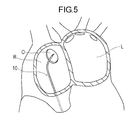
- It is sectional drawing which shows the state at the time of puncturing with a medical device (A) is the state which inserted the medical device into the right atrium, (B) is the state which inserted the guide wire into the left atrium, (C) is an outer sheath. The state which pulled out the dilator from is shown.
- FIG. 1 It is a figure which shows the 3rd modification of a medical device, (A) is a longitudinal cross-sectional view, (B) is a cross-sectional view which follows the AA line of (A). It is a cross-sectional view which shows the modification of a medical device, (A) shows a 4th modification, (B) shows a 5th modification. It is a figure which shows the 6th modification of a medical device, (A) is a longitudinal cross-sectional view, (B) is a cross-sectional view which follows the BB line of (A). It is sectional drawing which shows the modification of a medical device, (A) shows a 7th modification, (B) shows an 8th modification.
- distal side the side of the device that is inserted into the blood vessel
- proximal side the proximal side that is operated
- the medical device 10 is used to form an access route from the right atrium R to the left atrium L by forming a hole from the right atrium R to the oval fossa O of the atrial septum (FIG. 5). See).
- a plurality of treatment devices inserted percutaneously into the vena cava can be guided to the right atrium R and then easily inserted into the left atrium.
- the treatment device is, for example, an ablation catheter, a ring catheter, or the like.
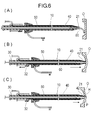
- the medical device 10 includes a dilator 40 (long body), an energy output unit 20, an operation unit 30, and an outer sheath 50 as shown in FIGS.
- the dilator 40 is used to widen the hole of the oval fossa O formed by the energy output unit 20.
- the dilator 40 includes a dilator center portion 41 having a substantially constant outer diameter, a tip portion 42 located on the distal side of the dilator center portion 41, and a dilator proximal portion 43 located on the proximal side of the dilator center portion 41.
- the dilator central portion 41 is a tubular body having a substantially constant outer diameter.
- the tip end portion 42 has an outer diameter that decreases in a tapered manner toward the distal side.
- the inclination angle ⁇ 1 with respect to the central axis of the outer peripheral surface of the distal end portion 42 is appropriately set, and is, for example, 1 to 80 degrees, more preferably 1 to 30 degrees, and further preferably 1 to 10 degrees.
- the dilator proximal portion 43 has a luer taper shape, and has a male connector 44 that can be connected to a connector with a lock on the outer peripheral surface.
- a first lumen 45 (lumen), a second lumen 46, and a third lumen 47 are formed.
- the first lumen 45 is located at the center of the dilator 40 in a cross section perpendicular to the central axis of the dilator 40.
- the first lumen 45 penetrates the dilator 40 in the axial direction.
- the first lumen 45 opens at the distal end of the distal end portion 42 with the most reduced diameter.
- the first lumen 45 can accommodate a guide wire.
- the second lumen 46 accommodates the conducting wire 22 of the energy output unit 20.
- the second lumen 46 opens at the distal end of the dilator 40 and opens near the operation unit 30 of the dilator 40.
- the third lumen 47 accommodates an operation wire 35 for bending the dilator 40.
- the third lumen 47 opens near the operation portion 30 of the dilator 40 and extends to the distal portion of the dilator 40.
- the third lumen 47 may open to the outside at the distal portion of the dilator 40, but may not open.
- the first lumen 45 has a distal lumen 45A on the distal side, a proximal lumen 45B having a larger inner diameter than the distal lumen 45A, and an inner diameter between the distal lumen 45A and the proximal lumen 45B. Is provided with a central lumen 45C.
- the inner diameter of the proximal lumen 45B is sufficiently larger than the outer diameter of the inserted guide wire. For this reason, the guide wire inserted into the proximal lumen 45 ⁇ / b> B can move smoothly along the inner peripheral surface of the dilator 40.
- the central lumen 45C smoothly guides the guide wire through the proximal lumen 45B to the distal lumen 45A.
- the inner diameter of the distal lumen 45A is an inner diameter that allows the guide wire to slide while contacting with a small clearance. Thereby, the outer diameter of the end part of the distal side of the dilator 40 becomes small, and it can enter smoothly into the hole of a biological tissue.
- the dilator 40 has a dilator bending portion 48 (bending portion) bent at a predetermined angle at the distal portion in a natural state where no external force acts.
- the dilator bending portion 48 serves to direct the distal portion of the dilator 40 toward the foveal fossa O.
- the direction in which the dilator bending portion 48 is bent toward the distal side coincides with the direction in which the third lumen 47 is provided with respect to the central axis of the dilator 40.
- the length of the dilator 40 in the axial direction is appropriately set, and is, for example, 500 to 800 mm.
- the outer diameter of the dilator 40 is set as appropriate, and is, for example, 1.0 to 10.0 mm.
- the inner diameter of the distal lumen 45A is appropriately set, and is, for example, 0.3 to 5.0 mm.
- the inner diameter of the second lumen 46 is appropriately set according to the outer diameter of the conducting wire 22 to be accommodated, and is, for example, 0.1 to 2.0 mm.
- the inner diameter of the third lumen 47 is appropriately set according to the outer diameter of the operation wire 35 to be accommodated, and is, for example, 0.1 to 2.0 mm.
- the angle ⁇ 1 of the dilator bending portion 48 with respect to the proximal portion of the dilator 40 is not particularly limited, but is, for example, 10 to 90 degrees, more preferably 30 to 80 degrees, and further preferably 40 to 70 degrees.
- the length from the distal end of the dilator 40 to the dilator bending portion 48 is appropriately set, and is, for example, 10 to 150 mm, more preferably 15 to 90 mm, and further preferably 20 to 70 mm.
- the constituent material of the dilator 40 is preferably flexible.
- polyolefin such as polyethylene and polypropylene
- polyester such as polyamide and polyethylene terephthalate
- PTFE polytetrafluoroethylene
- ETFE tetrafluoroethylene / ethylene copolymer
- Fluorine polymers such as coalescence
- PEEK polyetheretherketone
- polyimide shape memory alloy
- stainless steel tantalum, titanium, platinum, gold, tungsten, and other metals
- the dilator 40 may include an X-ray contrast material or a material with high ultrasonic visibility.
- the energy output unit 20 outputs energy for making a hole in the oval fossa O.
- the energy output unit 20 includes an output unit 21 that is an electrode disposed at a distal portion of the dilator 40 and a conductive wire 22 that is connected to the output unit 21 and transmits a current.
- the counter electrode plate which is an electrode which makes a pair with the output part 21 is affixed on the body surface.
- the conducting wire 22 passes through the second lumen 46.
- the distal end of the conducting wire 22 is connected to the output unit 21.
- the proximal end portion of the conducting wire 22 is led out from the second lumen 46 at the proximal portion of the dilator 40 and connected to the connector 36 of the operation portion 30.
- the connector 36 can be connected to an external power supply device that supplies a high-frequency current to the energy output unit 20.
- the conducting wire 22 may be disposed along the outer surface of the dilator 40 without being disposed in the second lumen 46. In this case, it is preferable that a groove in which the conducting wire 22 can be disposed is formed on the outer surface of the dilator 40.
- the surface of the conductor 22 is covered with an insulator.
- the output unit 21 heats and denatures the living tissue when a high-frequency current flows through the conductive wire 22 to form a hole.
- the output unit 21 is provided at the distal end of the tip 42.
- the output part 21 is joined (engaged) to the tip part 42 of the dilator 40 by adhesion or the like.
- the output unit 21 has a substantially cylindrical shape having the same central axis as the central axis of the dilator 40, and has a lumen that penetrates in the axial direction.
- the lumen of the output portion 21 communicates with the distal lumen 45A.
- the output unit 21 has a slit 23 formed in a part in the circumferential direction.
- the slit 23 is a cut extending from the distal end portion to the proximal end portion of the output portion 21 and penetrates from the outer surface to the inner surface of the output portion 21. Therefore, the shape of the output part 21 in a cross section perpendicular to the central axis of the dilator 40 is a C-shape.
- the output portion 21 has a concave shape on the side toward the central axis of the first lumen 45 when viewed from the distal side.
- the output unit 21 is provided in a range of less than 360 degrees in the direction surrounding the central axis of the dilator 40.
- the inner diameter of the inner peripheral surface of the output portion 21 matches the inner diameter of the distal lumen 45A. Thereby, a guide wire can be smoothly passed from the distal lumen 45 ⁇ / b> A to the output unit 21.
- the inner diameter of the output portion 21 may not match the inner diameter of the distal lumen 45A.
- the outer diameter of the outer peripheral surface of the output part 21 is smaller than the maximum outer diameter of the tip part 42 (the outer diameter of the dilator central part 41).
- the hole of the oval fossa O can be expanded by the tapered tip 42 without making the hole of the oval fossa O formed by the output part 21 too large. If the hole formed in the foveal fossa O is too large, the hole remains large after the procedure is completed, and blood flows between the right atrium R and the left atrium L through the hole. For this reason, it is preferable that the outer diameter of the output part 21 is not too large. Moreover, when the hole formed in the oval fossa O is too small, the resistance at the time of expanding a hole by the front-end
- the direction in which the slit 23 (notch) is provided coincides with the direction in which the third lumen 47 is provided with respect to the central axis of the dilator 40.
- the length of the output unit 21 in the axial direction is appropriately set, and is, for example, 0.1 to 5.0 mm, preferably 0.1 to 3.0 mm, and more preferably 0.1 to 1.5 mm.
- the angle at which the output unit 21 surrounds the central axis of the first lumen 45 is set as appropriate, and is, for example, 1 to 270 degrees, preferably 45 to 180 degrees.
- the outer diameter of the output unit 21 is appropriately set, and is, for example, 0.5 to 5.0 mm, preferably 0.5 to 4.0 mm, and more preferably 1.0 to 2.0 mm.
- the inner diameter of the output unit 21 is appropriately set, and is, for example, 0.3 to 4.5 mm, preferably 0.3 to 3.5 mm, and more preferably 0.5 to 1.5 mm.
- the output unit 21 of the energy output unit 20 does not have to be generated by a high-frequency current as long as it can denature living tissue to form a hole.
- the output unit 21 uses energy such as electromagnetic waves, lasers, and cooling
- the constituent material of the output unit 21 is not particularly limited as long as it has conductivity.
- stainless steel Au (gold), Pt (platinum), tungsten, titanium, or the like.
- the operation unit 30 includes a casing 31 fixed to the proximal portion of the dilator 40, a slide unit 32, an operation wire 35, and a connector 36.
- the slide part 32 is arranged in the casing 31 so as to be slidable along the axial direction of the dilator 40.
- the operation wire 35 is accommodated in the third lumen 47 of the dilator 40.
- a proximal end portion of the operation wire 35 is fixed to the slide portion 32.
- the distal end of the operation wire 35 is fixed to the distal portion of the dilator 40 inside the third lumen 47. Note that the distal end of the operation wire 35 may be fixed to the dilator 40 at a position derived from the third lumen 47 instead of inside the third lumen 47.
- the operation wire 35 may be fixed to any one of the distal portions of the energy output unit 20 (for example, the output unit 20) instead of the dilator 40.
- the direction in which the third lumen 47 is provided with respect to the central axis of the dilator 40 coincides with the direction in which the dilator bending portion 48 is bent toward the distal side. For this reason, when the slide part 32 is moved to the proximal side with respect to the casing 31, the operation wire 35 fixed to the slide part 32 moves to the proximal side in the third lumen 47. Thereby, contraction force acts on the side where the third lumen 47 is provided with respect to the central axis of the dilator 40.
- the dilator bending part 48 can be bent so that bending angle (beta) 1 may become large. Further, when the slide portion 32 is returned to the distal side with respect to the casing 31, the operation wire 35 moves in the third lumen 47 to the distal side. Thereby, the contraction force acting on the dilator 40 is reduced. For this reason, the dilator bending part 48 can return to the original shape. By changing the bending angle ⁇ 1 of the dilator bending portion 48, the dilator 40 can be directed in an appropriate direction.
- a first display portion 33 such as a scale is provided on the outer surface of the casing 31 along a movable range of the slide portion 32.
- a second display unit 34 that is paired with the first display unit 33 is provided on the outer surface of the slide unit 32.
- the 1st display part 33 and the 2nd display part 34 which are provided in the casing 31 and the slide part 32 may not be a scale, for example, may be a symbol, a figure, a character, etc.
- the first display unit 33 may be provided not on the casing 31 but on the outer peripheral surface of the dilator 40.
- the connector 36 is connected to the proximal end of the conducting wire 22 led out from the second lumen 46.
- the connector 36 can be connected to an external power supply device that supplies a high-frequency current to the energy output unit 20.
- the outer sheath 50 provides an access route for a treatment device such as an ablation catheter.
- the outer sheath 50 includes a sheath body 51, a hub 54 connected to the proximal portion of the sheath body 51, a port portion 56 communicating with the hub 54, and a valve body 55 inside the hub 54.
- the sheath body 51 is a long tube body that accommodates the dilator 40 so as to be movable in the axial direction.
- the sheath body 51 has an inner peripheral surface that slides smoothly with the dilator 40.
- the sheath body 51 has a sheath bent portion 52 bent at a predetermined angle at the distal portion in a natural state.
- the angle ⁇ 2 of the sheath bending portion 52 with respect to the proximal portion of the sheath body 51 is not particularly limited, but is, for example, 0 to 90 degrees, more preferably 20 to 70 degrees, and further preferably 30 to 60 degrees.
- the sheath bending part 52 plays a role of directing the output part 21 arranged in the dilator 40 inserted into the right atrium R toward the fossa ovum O.
- the sheath main body 51 has a sheath taper portion 53 whose diameter decreases in a tapered shape toward the distal side at the distal end portion.
- the lumen of the sheath body 51 is open at the end of the sheath taper portion 53 that has the smallest diameter.
- the inclination angle ⁇ 2 with respect to the central axis of the sheath taper portion 53 is appropriately set, and is, for example, 1 to 15 degrees, more preferably 2 to 10 degrees, and further preferably 3 to 7 degrees.
- the sheath taper portion 53 can be positioned on the proximal side of the tip portion 42 of the dilator 40 and can be continuous with the tip portion 42.
- the inner peripheral surface of the sheath body 51 preferably has a clearance between the outer peripheral surface of the dilator 40 and the outer peripheral surface of the dilator 40 so that the outer peripheral surface of the dilator 40 is slidably contacted.
- the dilator 40 can pass through the entire length of the sheath body 51. Therefore, the axial length of the sheath body 51 is shorter than that of the dilator 40.
- the axial length of the sheath body 51 is set as appropriate, and is, for example, 400 to 790 mm.
- the outer diameter of the sheath body 51 is set as appropriate, and is, for example, 1.1 to 11.0 mm.
- the inner diameter of the sheath body 51 is set as appropriate, and is, for example, 1.05 to 10.95 mm.
- the clearance at the radius between the inner peripheral surface of the sheath body 51 and the outer peripheral surface of the dilator 40 is set as appropriate, and is, for example, 0.01 to 1.00 mm.
- the constituent material of the sheath body 51 is preferably a flexible material.
- polyolefin such as polyethylene and polypropylene
- polyester such as polyamide and polyethylene terephthalate
- PTFE polytetrafluoroethylene
- ETFE tetrafluoroethylene
- a fluorine-based polymer such as an ethylene copolymer
- PEEK polyether ether ketone
- polyimide or the like can be preferably used.
- the hub 54 is provided at the proximal portion of the sheath body 51 and communicates with the lumen of the sheath body 51.
- the dilator 40 passes through the hub 54.
- the port portion 56 is connected to the hub 54 and communicates with the lumen of the sheath body 51 through the lumen of the hub 54.
- the port portion 56 has a three-way cock 57 at the end. By connecting a syringe or the like to the three-way cock 57, the lumen of the sheath body 51 can be primed, or a contrast agent, a drug, or the like can be injected into the sheath body 51.
- the valve body 55 is a member for sealing the lumens of the hub 54 and the sheath body 51.
- the valve body 55 can be flexibly deformed and is disposed on the inner peripheral surface of the hub 54.
- the valve body 55 is slidably in contact with the outer peripheral surface of the dilator 40. Further, the valve body 55 can press the dilator 40 with elastic force in a state where the dilator 40 is inserted, and can fix the dilator 40 and the outer sheath 50. Even if the valve body 55 is fixed, it can be relatively moved in the axial direction by gripping the dilator 40 and the outer sheath 50 and applying a force.
- the valve body 55 is a member having a cut in the center of a disk-like elastic body, for example.
- the elastic body include natural rubber, silicone rubber, and various elastomers.
- the valve body 55 suppresses blood from leaking through the outer sheath 50 while allowing the dilator 40 to be inserted and removed, and suppresses air from entering the body.
- the output unit 21 can be directed in a desired direction.
- a needle is punctured into the femoral vein, and a short guide wire is inserted into the needle.
- the needle is removed and a catheter introducer is inserted into the blood vessel along the short guide wire.
- the medical device 10 in which the dilator 40 is inserted into the outer sheath 50 is prepared (see FIG. 3).
- the short guide wire is removed, and the guide wire 60 is inserted into the catheter introducer.
- the catheter introducer is removed, the proximal end of the guide wire 60 is inserted into the lumen 45 from the distal end of the dilator 40, and the medical device 10. Is inserted into the blood vessel (step S10).
- the distal portion of the medical device 10 is gradually advanced to the right atrium R while the guide wire 60 is advanced.
- the medical device 10 is once inserted into the vena cava from the right atrium R along the guide wire 60.
- the distal end of the dilator 40 naturally moves to the vicinity of the foveal fossa O, as shown in FIGS. Led.
- the distal end portion of the guide wire 60 is drawn into the dilator 40 while confirming the X-ray image. Note that the guide wire 60 may be once removed from the dilator 40.
- the medical device 10 is pushed to the distal side while observing the left atrium L and the right atrium R with an intracardiac echo catheter (ICE: Intra cardiac echo catheter).
- ICE Intra cardiac echo catheter
- the angle ⁇ 1 of the dilator bending portion can be changed by moving the slide portion with respect to the casing 31. Thereby, the dilator 40 can be adjusted in a desired direction.
- the oval fossa O does not have to protrude to the left atrium L side.
- the output part 21 is located on the upper edge side of the egg fossa O on the side opposite to the side where the slit 23 is provided.
- the medical device 10 is pushed in while applying a high-frequency current to the output unit 21.
- the living tissue in contact with the output unit 21 is cauterized, and a hole H corresponding to the C-shape of the output unit 21 is formed (step S12).
- a hole H corresponding to the C-shape of the output unit 21 is formed (step S12).
- an outer edge portion E1 having a shape corresponding to the outer surface of the output portion 21, and a slit 23 of the output portion 21 and an inner edge portion E2 having a shape corresponding to the inner surface are formed.
- a portion surrounded by the inner edge E2 of the living tissue is a protrusion P that enters a space formed by cauterization.
- the output part 21 is located on the upper edge side of the oval fossa O on the side opposite to the side where the slits 23 are provided, it is easy to cauterize by contacting with the living tissue. After the output unit 21 penetrates the foveal fossa O and reaches the left atrium L, the supply of the high-frequency current to the output unit 21 is stopped.
- the cross-sectional shape of the output part with respect to the central axis of the dilator 40 is a ring shape
- the living tissue is cauterized by the output part, the part surrounded by the output part of the biological tissue is cut out into a cylindrical shape and the oval fossa Drop off from.
- the output unit 21 in the present embodiment is provided in a range of less than 360 degrees, the protrusion P does not fall off from the tissue of the oval fossa O. For this reason, debris flowing into the bloodstream does not occur, and safety is high.
- the protrusion P contacts the tapered tip 42 and is turned in the direction to be pushed into the dilator 40.
- the outer edge E1 having a shape corresponding to the outer surface of the output portion 21 is in contact with the tapered tip portion 42, expands in the radial direction of the hole, and can greatly expand the hole. Accordingly, the tapered tip end portion 42 increases the area of the hole, but does not increase the area of the protrusion P.
- cauterization proceeds more than the ratio of the area of the hole in the state where the hole immediately after the start of cauterization is not completely formed to the area of the protrusion P, and the hole is widened by the tapered tip 42.
- the ratio of the area of the hole in the state to the area of the protrusion P is larger.
- the tip 42 of the dilator 40 and the sheath taper 53 of the outer sheath 50 expand the hole H of the oval fossa O while expanding the oval fossa. Pass O and reach the left atrium L (step S13). Since the distal end portion 42 and the sheath taper portion 53 are reduced in diameter toward the distal side, the hole H of the oval fossa O can be smoothly expanded. At this time, since the protrusion P of the living tissue is flexible, it is pushed distally by the tip portion 42 and deformed to the left atrium L side.
- the protrusion P does not prevent the dilator 40 from being inserted into the hole H of the oval fossa O. Therefore, even if the hole H of the oval fossa O has the protrusion P, it can be greatly expanded according to the diameter of the outer edge E1 (see FIG. 7).
- the guide wire 60 located in the lumen 45 of the dilator 40 is moved to the distal side and protruded from the dilator 40. Thereby, the distal portion of the guide wire 60 reaches the left atrium L.
- the guide wire 60 may protrude from the dilator 40 and reach the left atrium L before the dilator 40 is pushed into the hole H after the hole H is formed in the oval fossa O by the output unit 21.
- the dilator 40 is removed from the body leaving the outer sheath 50 and the guide wire 60 (step S14).
- the hole H of the oval fossa O expanded by the dilator 40 is maintained by the outer sheath 50.
- the valve body 55 is closed, and leakage of blood and mixing of air or the like into the blood vessel can be suppressed.
- the guide wire 60 is inserted into the target site, and the second medical device such as the outer sheath 50 or the ablation device is inserted along the guide wire 60 (step S15).
- the guide wire 60 may be removed from the body, and the second medical device may be inserted without being along the guide wire 60.
- the second medical device is removed from the outer sheath 50 (step S17). Further, when the outer sheath 50 is removed, the hole H of the oval fossa O contracts. At this time, as shown in FIG. 7, the protrusion P returns to the hole H of the oval fossa O.
- the second medical device inserted into the living body via the outer sheath 50 is not limited to the ablation catheter.
- the position (target site) for inserting the second medical device via the outer sheath 50 is not limited to the pulmonary vein or the left atrium L, and may be, for example, the right atrium R, the left atrial appendage, and the mitral valve. .
- the medical device 10 is a medical device 10 for forming a hole H in the oval fossa O (living tissue) in a living body and expanding the hole H, A first lumen 45 is formed, and a dilator 40 (elongate body) having a distal end 42 that opens the first lumen 45 on the distal side, and a hole H is formed by denaturing the tissue of the oval fossa O.
- Output portion 21 that outputs energy for the purpose, and the output portion 21 is disposed at the distal end portion 42 and is provided discontinuously in the circumferential direction of the distal end portion 42. At least one outer diameter gradually decreases toward the distal side.
- the medical device 10 configured as described above is provided with the discontinuous output portion 21 in the circumferential direction of the distal end portion 42, it can maintain safety without the body tissue being hollowed out and using energy. Hole H can be formed. Furthermore, since the tip portion 42 whose outer diameter decreases toward the distal side is provided, the tip portion 42 is pushed into the formed hole H and passed through the foveal fossa O, thereby making the hole H easy and smooth. Can be extended. Since the output unit 21 is not accommodated in the first lumen 45 of the dilator 40, there is no need to insert the output unit 21 into the living body from the first lumen 45, and the internal space of the first lumen 45 is made empty. Therefore, it is not necessary to pull out the output unit 21 outside the living body.
- the guide wire 60 can be inserted into the hole H of the ovary fossa via the first lumen 45 opened at the distal end portion 42 without having to replace the guide wire 60 with the output portion 21. For this reason, it is possible to easily and quickly secure the hole H for inserting the treatment device, and it is possible to improve work efficiency.
- the output part 21 is located on the distal side of the tip part 42. Therefore, by pushing the medical device 10, the hole H of the oval fossa O formed by the output part 21 can be smoothly expanded by the tip part 42 pushed into the hole following the output part 21.
- the longest distance from the central axis of the output part 21 in the cross section perpendicular to the central axis of the dilator 40 (long body) is smaller than the maximum radius of the tip part 42. That is, the maximum outer diameter of the output portion 21 is smaller than the maximum outer diameter at the tip portion 42. Thereby, the hole H of the oval fossa O formed by the output part 21 can be effectively expanded by the front-end
- the output portion 21 has a concave shape surrounding the central axis of the first lumen 45 when viewed from the distal side. That is, the inner peripheral surface of the output unit 21 is not a convex shape or a planar shape but a concave shape that is recessed as a whole. In addition, even if a convex shape and planar shape partially exist in the inner peripheral surface of an output part, the output part should just be a concave shape as a whole seeing from a distal side. Thereby, a projection P protruding into the space inside the hole H is formed at the edge of the hole H of the oval fossa O by the concave portion of the output part 21. Since the protrusion P does not fall off from the surrounding living tissue and easily deforms, the hole H of the living tissue can be greatly expanded.
- the output unit 21 is provided in a range of 1 degree or more and less than 360 degrees in a direction surrounding the central axis of the first lumen 45.
- the large projection P which protrudes into the space inside the hole H is formed at the edge of the hole H of the living tissue by the output part 21 surrounding the central axis of the first lumen 45. Since the protrusion P does not fall off from the surrounding living tissue and easily deforms, the hole H of the oval fossa O can be greatly expanded.
- the angle at which the output unit 21 surrounds the central axis of the first lumen 45 is, for example, 1 degree or more, preferably 45 degrees or more, more preferably 90 degrees or more, further preferably 135 degrees or more, and further preferably 180 degrees. Above, more preferably 225 degrees or more, more preferably 270 degrees or more, and further preferably 315 degrees or more.
- a large protrusion P that protrudes into the space inside the hole H is formed at the edge of the hole H of the biological tissue. Since the large protrusion P is easily deformed, the hole H of the living tissue can be greatly expanded.
- the angle at which the output unit 21 surrounds the central axis of the first lumen 45 is less than 360 degrees, preferably less than 315 degrees, more preferably less than 270 degrees, still more preferably less than 270 degrees, and even more preferably 225. Less than 180 degrees, more preferably less than 180 degrees, more preferably 135 degrees or more, more preferably less than 90 degrees, and still more preferably less than 45 degrees. If the angle at which the output unit 21 surrounds the central axis of the first lumen 45 is too large, there is a possibility that the protrusion P will drop off from the surrounding biological tissue.
- the output unit 21 is a tubular body that is discontinuous in the circumferential direction having a slit 23 (notch).
- a large protrusion P that protrudes into the space inside the hole H is formed at the edge of the hole H of the living tissue.
- the cross-sectional shape of the discontinuous tube is not limited to a perfect circle, and may be, for example, an ellipse, a quadrangle, a triangle, or the like.
- the output unit 21 is located on the distal end face of the dilator 40 (long body) and has a slit 23 (notch) extending in the axial direction.
- the distal end face of the dilator 40 is The ring is continuous. Thereby, the protrusion P formed by the output part 21 can be pushed in by the dilator 40 which continues in a ring shape, and the hole H can be greatly expanded. Since the end surface of the dilator 40 is continuous in a ring shape, the protrusion P is prevented from entering the first lumen 45 of the dilator 40, and the protrusion P is prevented from interfering with a device passing through the first lumen 45. it can.
- the dilator 40 has a dilator bending portion 48 (bending portion) that bends to one side toward the distal side.
- the direction in which the output portion 21 is located with respect to the central axis of the dilator 40 is determined by the dilator bending portion 48.
- the direction is opposite to the direction of bending toward the distal side. That is, the direction in which the slit 23 is positioned with respect to the central axis of the dilator 40 is the same as the direction in which the dilator bending portion 48 is bent toward the distal side.
- the ablation device 70 has a power receiving unit 71 that is electrically connected to an ablation electrode 72 at the tip at a site where the output unit 21 contacts.
- the ablation device 70 can receive current from the power receiving unit 71 and perform ablation with the electrode 72.
- the direction in which the output unit 21 is positioned with respect to the central axis of the dilator 40 may be the same direction as the direction in which the dilator bending unit 48 bends toward the distal side.
- the guide wire 60 and the ablation device 70 passing through the first lumen 45 are difficult to contact the output unit 21, and interference between the output unit 21 and other members can be suppressed.
- the medical device 10 has an operation wire 35 extending along the axial direction of the dilator 40, and a distal portion of the operation wire 35 is a distal portion of the dilator 40 or a distal portion of the energy output unit 20. It is connected to. Thereby, the dilator 40 can be bent by pulling the operation wire 35. For this reason, the position which forms the hole H of the oval fossa O can be adjusted easily.
- the present invention also includes a treatment method (therapeutic method) for forming a hole H in the oval fossa O (living tissue) in the living body and expanding the hole H using the medical device 10 described above.
- the treatment method includes step S10 in which the distal portion of the medical device 10 is inserted into the living body, step S12 in which the output unit 21 is brought into contact with the foveal fossa O to form a hole H in the foveal fossa O, and a dilator. And step S13 of moving the distal end 40 to the distal side and expanding the hole H of the oval fossa O by at least one of the tip portion 42 and the output portion 21.
- the hole H is formed by the output portion 21 provided in a range of less than 360 degrees in the direction surrounding the central axis of the first lumen 45 opened at the distal end portion 42, the living tissue is formed. It is possible to maintain safety without being cut out and falling off, and the hole H can be formed using energy. Furthermore, since the tip part 42 is pushed into the formed hole H to widen the oval fossa O, the hole H can be easily and smoothly expanded. And since the output part 21 is not accommodated in the 1st lumen
- the living tissue pierced by the medical device 10 may not be the foveal fossa O.
- the output portion 80 which is an electrode, is partially cut in the circumferential direction so as to be cut along a plane parallel to the central axis of the first lumen 45. May be provided.
- symbol is attached
- the output unit 90 may be provided in a range of less than 180 degrees in a direction surrounding the central axis of the first lumen 45.
- the output unit 100 may have a tapered outer diameter that is reduced in diameter toward the distal side.
- the output unit 100 is smoothly continuous with the tapered tip 111 of the dilator 110.
- a compensation unit 112 that constitutes the tip 111 of the dilator 110 is provided smoothly and continuously with the outer peripheral surface of the output unit 100.
- the surface 101 connected to the filling portion 112 of the output unit 100 may be formed with a plurality of irregularities in order to increase the bonding force. Note that the compensation unit 112 may not be provided.
- the output unit 120 may be formed in a crescent shape in a cross-sectional shape perpendicular to the central axis of the first lumen 45. At the joint between the output unit 120 and the compensation unit 121, the output unit 120 is located on the outer side in the radial direction of the compensation unit 121.
- the compensation part 131 that is discontinuous in the circumferential direction of the output part 130 may be formed in a crescent shape. At the joint between the output unit 130 and the compensation unit 131, the compensation unit 131 is located on the outer side in the radial direction of the output unit 130.
- the output unit 140 may be disposed so as to cover the distal portion of the tip portion 151 of the dilator 150.
- the outer peripheral surfaces of the tip portion 151 and the output portion 140 are smoothly continuous. Thereby, the output part 140 and the front-end
- the output unit 160 may be provided more proximally than the most distal portion of the tip 171 of the dilator 170. Even in such a configuration, the tip portion 171 can bite into the living tissue and the output unit 160 can contact the living tissue by abutting the dilator 170 against the living tissue. Therefore, even with such a configuration, the output unit 160 can form a hole in the living tissue and push the dilator 170 into the hole.
- the output unit 180 may be provided from the distal side to the proximal side of the tip portion 191 of the dilator 190.
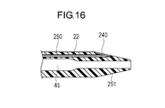
- the output unit 240 is not provided at the distal portion of the tip portion 251 of the dilator 250 but is provided at the proximal portion of the tip portion 251. Also good. Thereby, a hole having a large outer edge E1 can be formed in the output unit 240 while reducing the range in which the living tissue is destroyed by the output unit 240.
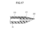
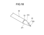
- the output unit 200 may not have a concave shape on the side toward the central axis of the first lumen 45 when viewed from the distal side.
- the output unit 200 has a cylindrical shape, for example. Even in such a configuration, the output unit 200 is discontinuously provided in the circumferential direction of the distal end portion 211. For this reason, after a hole is formed in the living tissue by the output unit 200, the distal end portion 211 where the first lumen 45 of the dilator 210 opens can be inserted into the hole.
- the first lumen 45 may be opened on the inclined surface of the distal end portion 211.
- the opening of the first lumen 45 is inclined with respect to a plane perpendicular to the central axis of the first lumen 45. Therefore, when inserting the front-end
- the opening of the first lumen 45 may be formed in a plane perpendicular to the central axis of the first lumen 45.
- the output unit 200 may have a wire shape instead of a plate shape.
- the output unit 200 is provided on the outer surface of the tip 221 of the dilator 220.
- the shape of the output part 200 is not specifically limited, For example, both ends are located in the vicinity of the opening of the 1st lumen 45, and the center is curving toward the proximal side.
- the output unit may be a bipolar electrode having two electrodes.
- a counter electrode paired with the output unit is provided at any one of the distal end portions in contact with the living tissue.
- the electrode area exposed by the counter electrode plate is larger than the area of the output part.
Landscapes
- Health & Medical Sciences (AREA)
- Life Sciences & Earth Sciences (AREA)
- Surgery (AREA)
- Engineering & Computer Science (AREA)
- Public Health (AREA)
- Animal Behavior & Ethology (AREA)
- Biomedical Technology (AREA)
- Heart & Thoracic Surgery (AREA)
- Veterinary Medicine (AREA)
- General Health & Medical Sciences (AREA)
- Molecular Biology (AREA)
- Medical Informatics (AREA)
- Nuclear Medicine, Radiotherapy & Molecular Imaging (AREA)
- Pathology (AREA)
- Otolaryngology (AREA)
- Physics & Mathematics (AREA)
- Plasma & Fusion (AREA)
- Anesthesiology (AREA)
- Biophysics (AREA)
- Pulmonology (AREA)
- Hematology (AREA)
- Cardiology (AREA)
- Surgical Instruments (AREA)
- Media Introduction/Drainage Providing Device (AREA)
Priority Applications (4)
| Application Number | Priority Date | Filing Date | Title |
|---|---|---|---|
| CN201780060618.9A CN109803597B (zh) | 2016-09-30 | 2017-09-28 | 医疗设备和处置方法 |
| JP2018542856A JP6917381B2 (ja) | 2016-09-30 | 2017-09-28 | 医療デバイス |
| EP17856336.7A EP3520724A4 (de) | 2016-09-30 | 2017-09-28 | Medizinische vorrichtung und behandlungsverfahren |
| US16/364,981 US20190216503A1 (en) | 2016-09-30 | 2019-03-26 | Medical device and treatment method |
Applications Claiming Priority (2)
| Application Number | Priority Date | Filing Date | Title |
|---|---|---|---|
| JP2016193183 | 2016-09-30 | ||
| JP2016-193183 | 2016-09-30 |
Related Child Applications (1)
| Application Number | Title | Priority Date | Filing Date |
|---|---|---|---|
| US16/364,981 Continuation US20190216503A1 (en) | 2016-09-30 | 2019-03-26 | Medical device and treatment method |
Publications (1)
| Publication Number | Publication Date |
|---|---|
| WO2018062387A1 true WO2018062387A1 (ja) | 2018-04-05 |
Family
ID=61762657
Family Applications (1)
| Application Number | Title | Priority Date | Filing Date |
|---|---|---|---|
| PCT/JP2017/035214 WO2018062387A1 (ja) | 2016-09-30 | 2017-09-28 | 医療デバイスおよび処置方法 |
Country Status (5)
| Country | Link |
|---|---|
| US (1) | US20190216503A1 (de) |
| EP (1) | EP3520724A4 (de) |
| JP (1) | JP6917381B2 (de) |
| CN (1) | CN109803597B (de) |
| WO (1) | WO2018062387A1 (de) |
Cited By (1)
| Publication number | Priority date | Publication date | Assignee | Title |
|---|---|---|---|---|
| EP3769708A4 (de) * | 2018-03-20 | 2021-04-28 | TERUMO Kabushiki Kaisha | Medizinprodukt |
Families Citing this family (3)
| Publication number | Priority date | Publication date | Assignee | Title |
|---|---|---|---|---|
| US11931098B2 (en) * | 2020-02-19 | 2024-03-19 | Boston Scientific Medical Device Limited | System and method for carrying out a medical procedure |
| US20210401458A1 (en) * | 2020-06-25 | 2021-12-30 | Covidien Lp | Obturator having a distal electrode |
| CN113796954B (zh) * | 2021-10-11 | 2023-03-28 | 杭州市第一人民医院 | 一种可改变加热角度的消融针 |
Citations (5)
| Publication number | Priority date | Publication date | Assignee | Title |
|---|---|---|---|---|
| JPH06142111A (ja) * | 1992-04-14 | 1994-05-24 | Olympus Optical Co Ltd | トラカール |
| JP2554849B2 (ja) * | 1992-06-30 | 1996-11-20 | ヴァリーラブ・インコーポレーテッド | 電気外科用管状トロカール |
| JP2000201946A (ja) | 1999-01-14 | 2000-07-25 | Olympus Optical Co Ltd | レゼクトスコ―プ装置 |
| JP2012050538A (ja) * | 2010-08-31 | 2012-03-15 | Terumo Corp | アブレーションデバイス |
| JP2016193183A (ja) | 2015-03-31 | 2016-11-17 | 株式会社ジェイマックシステム | 画像処理装置、画像処理方法、画像処理プログラムおよび検像システム |
Family Cites Families (15)
| Publication number | Priority date | Publication date | Assignee | Title |
|---|---|---|---|---|
| US5423330A (en) * | 1993-03-10 | 1995-06-13 | The University Of Miami | Capsule suction punch instrument and method of use |
| CA2159981A1 (en) * | 1993-04-09 | 1994-10-27 | Charles C. Hart | Surgical trocar with cutoff circuit |
| US6302898B1 (en) * | 1994-06-24 | 2001-10-16 | Advanced Closure Systems, Inc. | Devices for sealing punctures in body vessels |
| WO2000038574A1 (en) * | 1998-12-23 | 2000-07-06 | Nuvasive, Inc. | Nerve surveillance cannulae systems |
| US6770070B1 (en) * | 2000-03-17 | 2004-08-03 | Rita Medical Systems, Inc. | Lung treatment apparatus and method |
| ATE497733T1 (de) * | 2001-12-28 | 2011-02-15 | Olympus Corp | Behandlungsvorrichtung zum schneiden von lebendem gewebe |
| JP2005348820A (ja) * | 2004-06-08 | 2005-12-22 | Olympus Corp | 発熱素子、それを用いた医療用処置具、処置装置 |
| US8187272B2 (en) * | 2006-10-06 | 2012-05-29 | Biomedcraft Designs, Inc. | Surgical instrument for coagulation and suction |
| ATE481936T1 (de) * | 2007-06-25 | 2010-10-15 | Terumo Corp | Medizinische vorrichtung |
| WO2009048824A1 (en) * | 2007-10-09 | 2009-04-16 | Boston Scientific Scimed, Inc. | Electrophysiology electrodes and apparatus including the same |
| US8500697B2 (en) * | 2007-10-19 | 2013-08-06 | Pressure Products Medical Supplies, Inc. | Transseptal guidewire |
| US8882761B2 (en) * | 2008-07-15 | 2014-11-11 | Catheffects, Inc. | Catheter and method for improved ablation |
| EP2468206A1 (de) * | 2009-06-09 | 2012-06-27 | U & I Corporation | Richtungssteuerbarer Elektrodenkörper zum selektiven Entfernen von Körpergewebe und Führungsrohr |
| US9668807B2 (en) * | 2012-05-01 | 2017-06-06 | Covidien Lp | Simplified spring load mechanism for delivering shaft force of a surgical instrument |
| CN102860868B (zh) * | 2012-08-13 | 2016-03-30 | 中美联合技术(北京)有限公司 | 双极手术电极的注水系统及方法 |
-
2017
- 2017-09-28 CN CN201780060618.9A patent/CN109803597B/zh active Active
- 2017-09-28 JP JP2018542856A patent/JP6917381B2/ja active Active
- 2017-09-28 EP EP17856336.7A patent/EP3520724A4/de active Pending
- 2017-09-28 WO PCT/JP2017/035214 patent/WO2018062387A1/ja unknown
-
2019
- 2019-03-26 US US16/364,981 patent/US20190216503A1/en active Pending
Patent Citations (5)
| Publication number | Priority date | Publication date | Assignee | Title |
|---|---|---|---|---|
| JPH06142111A (ja) * | 1992-04-14 | 1994-05-24 | Olympus Optical Co Ltd | トラカール |
| JP2554849B2 (ja) * | 1992-06-30 | 1996-11-20 | ヴァリーラブ・インコーポレーテッド | 電気外科用管状トロカール |
| JP2000201946A (ja) | 1999-01-14 | 2000-07-25 | Olympus Optical Co Ltd | レゼクトスコ―プ装置 |
| JP2012050538A (ja) * | 2010-08-31 | 2012-03-15 | Terumo Corp | アブレーションデバイス |
| JP2016193183A (ja) | 2015-03-31 | 2016-11-17 | 株式会社ジェイマックシステム | 画像処理装置、画像処理方法、画像処理プログラムおよび検像システム |
Non-Patent Citations (1)
| Title |
|---|
| See also references of EP3520724A4 |
Cited By (1)
| Publication number | Priority date | Publication date | Assignee | Title |
|---|---|---|---|---|
| EP3769708A4 (de) * | 2018-03-20 | 2021-04-28 | TERUMO Kabushiki Kaisha | Medizinprodukt |
Also Published As
| Publication number | Publication date |
|---|---|
| CN109803597B (zh) | 2021-10-12 |
| US20190216503A1 (en) | 2019-07-18 |
| JPWO2018062387A1 (ja) | 2019-08-08 |
| CN109803597A (zh) | 2019-05-24 |
| JP6917381B2 (ja) | 2021-08-11 |
| EP3520724A4 (de) | 2020-04-22 |
| EP3520724A1 (de) | 2019-08-07 |
Similar Documents
| Publication | Publication Date | Title |
|---|---|---|
| US20210007790A1 (en) | Medical device and treatment method | |
| JP7309688B2 (ja) | 医療デバイス | |
| EP3777741B1 (de) | Medizinische vorrichtung | |
| US20190216503A1 (en) | Medical device and treatment method | |
| EP3603727B1 (de) | Führungsdraht, medizinische vorrichtung | |
| WO2019181612A1 (ja) | 医療デバイス | |
| WO2019181634A1 (ja) | 医療デバイス | |
| EP4042960B1 (de) | Medizinische vorrichtung | |
| JP7197559B2 (ja) | ガイドワイヤおよび医療デバイス | |
| JP7078606B2 (ja) | 穿刺デバイスおよび医療デバイス | |
| WO2018047901A1 (ja) | 医療デバイスおよび処置方法 | |
| JP2018051146A (ja) | ダイレータおよび医療システム並びに処置方法 | |
| WO2018079508A1 (ja) | 医療デバイスおよび処置方法 | |
| JP2022547703A (ja) | 吻合を形成するシステム、装置及び方法 | |
| WO2018062386A1 (ja) | 医療システムおよびダイレータ並びに処置方法 | |
| JP6847617B2 (ja) | 医療システムおよび医療デバイス | |
| WO2018083685A1 (ja) | 医療デバイスおよび処置方法 | |
| CN117653322A (zh) | 用于实现稳定出针的引导组件、消融装置及消融系统 |
Legal Events
| Date | Code | Title | Description |
|---|---|---|---|
| 121 | Ep: the epo has been informed by wipo that ep was designated in this application |
Ref document number: 17856336 Country of ref document: EP Kind code of ref document: A1 |
|
| ENP | Entry into the national phase |
Ref document number: 2018542856 Country of ref document: JP Kind code of ref document: A |
|
| NENP | Non-entry into the national phase |
Ref country code: DE |
|
| ENP | Entry into the national phase |
Ref document number: 2017856336 Country of ref document: EP Effective date: 20190430 |