WO2018062152A1 - 医療用リーク検査装置 - Google Patents
医療用リーク検査装置 Download PDFInfo
- Publication number
- WO2018062152A1 WO2018062152A1 PCT/JP2017/034692 JP2017034692W WO2018062152A1 WO 2018062152 A1 WO2018062152 A1 WO 2018062152A1 JP 2017034692 W JP2017034692 W JP 2017034692W WO 2018062152 A1 WO2018062152 A1 WO 2018062152A1
- Authority
- WO
- WIPO (PCT)
- Prior art keywords
- balloon
- tubular
- tubular body
- balloon member
- medical leak
- Prior art date
- Legal status (The legal status is an assumption and is not a legal conclusion. Google has not performed a legal analysis and makes no representation as to the accuracy of the status listed.)
- Ceased
Links
Images









Classifications
-
- A—HUMAN NECESSITIES
- A61—MEDICAL OR VETERINARY SCIENCE; HYGIENE
- A61B—DIAGNOSIS; SURGERY; IDENTIFICATION
- A61B1/00—Instruments for performing medical examinations of the interior of cavities or tubes of the body by visual or photographical inspection, e.g. endoscopes; Illuminating arrangements therefor
- A61B1/313—Instruments for performing medical examinations of the interior of cavities or tubes of the body by visual or photographical inspection, e.g. endoscopes; Illuminating arrangements therefor for introducing through surgical openings, e.g. laparoscopes
- A61B1/3137—Instruments for performing medical examinations of the interior of cavities or tubes of the body by visual or photographical inspection, e.g. endoscopes; Illuminating arrangements therefor for introducing through surgical openings, e.g. laparoscopes for examination of the interior of blood vessels
-
- A—HUMAN NECESSITIES
- A61—MEDICAL OR VETERINARY SCIENCE; HYGIENE
- A61B—DIAGNOSIS; SURGERY; IDENTIFICATION
- A61B1/00—Instruments for performing medical examinations of the interior of cavities or tubes of the body by visual or photographical inspection, e.g. endoscopes; Illuminating arrangements therefor
- A61B1/00064—Constructional details of the endoscope body
- A61B1/00071—Insertion part of the endoscope body
- A61B1/0008—Insertion part of the endoscope body characterised by distal tip features
- A61B1/00082—Balloons
-
- A—HUMAN NECESSITIES
- A61—MEDICAL OR VETERINARY SCIENCE; HYGIENE
- A61B—DIAGNOSIS; SURGERY; IDENTIFICATION
- A61B1/00—Instruments for performing medical examinations of the interior of cavities or tubes of the body by visual or photographical inspection, e.g. endoscopes; Illuminating arrangements therefor
- A61B1/00131—Accessories for endoscopes
- A61B1/0014—Fastening element for attaching accessories to the outside of an endoscope, e.g. clips, clamps or bands
-
- A—HUMAN NECESSITIES
- A61—MEDICAL OR VETERINARY SCIENCE; HYGIENE
- A61B—DIAGNOSIS; SURGERY; IDENTIFICATION
- A61B1/00—Instruments for performing medical examinations of the interior of cavities or tubes of the body by visual or photographical inspection, e.g. endoscopes; Illuminating arrangements therefor
- A61B1/005—Flexible endoscopes
- A61B1/01—Guiding arrangements therefore
-
- G—PHYSICS
- G02—OPTICS
- G02B—OPTICAL ELEMENTS, SYSTEMS OR APPARATUS
- G02B23/00—Telescopes, e.g. binoculars; Periscopes; Instruments for viewing the inside of hollow bodies; Viewfinders; Optical aiming or sighting devices
- G02B23/24—Instruments or systems for viewing the inside of hollow bodies, e.g. fibrescopes
- G02B23/2476—Non-optical details, e.g. housings, mountings, supports
Definitions
- the present invention relates to a medical leak inspection apparatus.
- This application is filed in Japanese Patent Application No. 2016-189472 filed in Japan on September 28, 2016, Japanese Patent Application No. 2016-189473 filed in Japan on September 28, 2016, and in Japan on September 19, 2017. Claiming priority based on Japanese Patent Application No. 2017-179576 filed and Japanese Patent Application No. 2017-179579 filed in Japan on September 19, 2017, the contents of which are incorporated herein by reference.
- Patent Documents 1 and 2 describe a medical leak inspection apparatus for inspecting whether or not the function of an arterial valve is normal.
- the medical leak test apparatus described in these documents is provided along the cylindrical portion, the visual window portion closing the front end portion or the rear end portion of the cylindrical portion, and the outer peripheral surface of the cylindrical portion.
- a balloon member is provided along the cylindrical portion, the visual window portion closing the front end portion or the rear end portion of the cylindrical portion, and the outer peripheral surface of the cylindrical portion.
- the medical leak inspection apparatus of Patent Document 1 has a visual window on the rear end side of the cylindrical portion, and a front portion thereof is a concave portion. For this reason, the visual recognition window portion is arranged close to the user, and a good visual field can be obtained in the inspection.
- the medical leak test apparatus is placed on the artery by injecting a fluid into the balloon member and inflating the balloon member with the medical leak test apparatus disposed on the downstream side of the arterial valve. Fix it.
- a liquid is injected into the space to fill the space.
- the function of the arterial valve is examined by monitoring the fluid pressure or amount of the space or by visually observing the arterial valve through the visual window.
- the present invention has been made in view of the above-described problems, and provides a medical leak inspection apparatus capable of ensuring a good visual field through a visual recognition window.
- a main body having a cylindrical part having a communication hole formed in a peripheral wall, a visual window part closing the cylindrical part, and the cylindrical part
- a balloon member provided along the outer peripheral surface and inflating toward the outside of the cylindrical portion; a balloon pipe for injecting and discharging a fluid between the balloon member and the cylindrical portion;
- a tubular body on which an injection lumen for injecting liquid into the space in front of the visual recognition window portion and an exhaust lumen for exhausting air from the space in front of the visual recognition window portion;
- a medical leak test apparatus is provided.
- the second aspect of the present invention has a cylindrical part and a visual window part closing the cylindrical part, and a concave part is formed forward by the cylindrical part and the visual window part.
- a balloon member that is provided along the outer peripheral surface of the main body portion and the cylindrical portion, and expands toward the outside of the cylindrical portion by introducing a fluid between the cylindrical portion.
- a tubular body in which an injection lumen for injecting liquid into the space in front of the visual recognition window portion and an exhaust lumen for exhausting air from the space in front of the visual recognition window portion are formed.
- a medical leak inspection apparatus is provided along the outer peripheral surface of the main body portion and the cylindrical portion, and expands toward the outside of the cylindrical portion by introducing a fluid between the cylindrical portion.
- a tubular body in which an injection lumen for injecting liquid into the space in front of the visual recognition window portion and an exhaust lumen for exhausting air from the space in front of the visual recognition window portion are formed.
- the medical leak test apparatus of the present invention it is possible to secure a good visual field through the visual window part by the liquid injection lumen for injecting liquid into the space in front of the visual window part. It is.
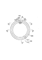
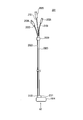
- FIG. 1 is an overall view of a medical leak inspection apparatus according to a first embodiment. It is the front view seen from the arrow A1 direction of FIG.
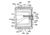
- FIG. 3 is a cross-sectional view taken along line B1-B1 of FIG.
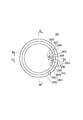
- FIG. 3 is a cross-sectional view taken along line C1-C1 in FIG.
- FIG. 3 is a cross-sectional view taken along line D1-D1 of FIG.
- FIG. 15 is a cross-sectional view taken along the line C2-C2 of FIG. 14 for a medical leak test apparatus including a fog occurrence suppressing unit according to an eighth embodiment.
- FIG. 15 is a cross-sectional view taken along the line C2-C2 of FIG. 14 for a medical leak test apparatus including a fog generation suppressing unit according to a ninth embodiment.
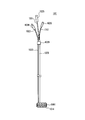
- FIG. 1 is an overall view of a medical leak inspection apparatus according to the first embodiment.
- FIG. 2 is a front view seen from the direction of arrow A1 in FIG.
- FIG. 3 is a cross-sectional view taken along the line B1-B1 of FIG. 4 is a cross-sectional view taken along line C1-C1 in FIG.
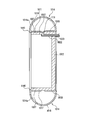
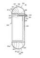
- FIG. 5 is a cross-sectional view taken along line D1-D1 in FIG. 6 is a cross-sectional view showing a state in which the balloon member of the medical leak test apparatus of FIG. 5 is inflated.
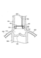
- FIG. 7 is a cross-sectional view for explaining an example of use of the medical leak test apparatus according to the first embodiment.
- the medical leak test apparatus 101 includes a main body 1013 having a cylindrical portion 1011 having a communication hole 1111 formed in the peripheral wall and a visual window portion 1012 closing the cylindrical portion 1011; A balloon member 1014, a tubular body 1023 in which an injection lumen 1015 and an exhaust lumen 1016 are formed, and a balloon pipe 1022 are provided.
- the balloon member 1014 is a member that is provided along the outer peripheral surface 1017 of the tubular portion 1011 and expands toward the outside of the tubular portion 1011.
- the injection lumen 1015 is a lumen for injecting a fluid such as a myocardial protective solution into the space 1018 in front of the visual recognition window portion 1012.
- the myocardial protective solution injected into the space 1018 prevents ischemia when the heart muscle is stopped, and has a low temperature of about 4 ° C.
- the metabolism is suppressed by the heart becoming cold by the myocardial protective solution.
- the exhaust lumen 1016 is a lumen for exhausting air from the space 1018 in front of the visual window portion 1012.
- An injection pipe 1151 is continuously provided on the rear end side of the injection lumen 1015.
- An exhaust pipe 1161 is continuously provided on the rear end side of the exhaust lumen 1016.
- the balloon pipe 1022 is a tube-like member for injecting fluid between the balloon member 1014 and the cylindrical portion 1011 and discharging the fluid.
- the front end of the balloon member 1014 is a front folded portion 1027 folded back, and the front folded portion 1027 is fixed to the outer peripheral surface 1017 other than the site where the communication hole 1111 of the cylindrical portion 1011 is formed.
- the rear end of the balloon member 1014 is a rear folded portion 1028 that is folded forward, and the rear folded portion 1028 is fixed to the outer peripheral surface 1017 other than the site where the communication hole 1111 of the cylindrical portion 1011 is formed. Has been.
- the cylindrical portion 1011 of the main body portion 1013 is cylindrical, and the visual window portion 1012 closes the rear end portion of the cylindrical portion 1011.
- the viewing window portion 1012 has a plate shape, and its plate surface is orthogonal to the axial center of the cylindrical portion 1011.
- the cylindrical portion 1011 and the visual recognition window portion 1012 form a concave shape in front of the main body portion 1013.
- the viewing window portion 1012 contains a filler 1041 (see FIG. 4) that suppresses the occurrence of fogging due to condensation.
- the filler 1041 is made of SiO 2 (silica) or the like having higher heat insulating properties than polycarbonate or the like, which is a base material of the visual window portion 1012, and is integrally formed by kneading the visual window portion 1012. As described above, the filler 1041 having heat insulation properties is kneaded in the visual recognition window portion 1012, so that the myocardial protective solution injected from the injection lumen 1015 into the concave portion formed on the distal end side of the cylindrical portion 1011. And the movement of heat between the viewing window portion 1012 can be prevented. For this reason, it can prevent that dew condensation arises on the surface of the back side of the window part 1012 for visual recognition.
- the viewing window portion 1012 may have a two-layer structure including a polycarbonate layer and a layer in which a filler 1041 is kneaded with polycarbonate.
- a layer in which the filler 1041 is kneaded rather than the polycarbonate layer is disposed on the rear side, it is suitable for suppressing the occurrence of condensation.
- the visual recognition window portion 1012 may be configured to close not the rear end portion of the tubular portion 1011 but a midway portion in the axial direction.
- a concave shape is formed in front of the main body portion 1013 by such an aspect.
- the main body portion 1013 including the cylindrical portion 1011 and the viewing window portion 1012 is integrally formed of a single material.
- the main body 1013 is made of a hard and transparent resin material such as polycarbonate.
- the length of the cylindrical portion 1011 in the axial direction is preferably shorter than the diameter of the cylindrical portion 1011.
- the visual inspection window portion 1012 can be brought closer to the observation target site (for example, the aortic valve) and the medical leak test apparatus 101 can be used, so that the visibility of the observation target site is improved. Can be made.
- the tubular portion 1011 is formed with a communication hole 1111 that penetrates the peripheral wall. Inside the tubular portion 1011, a balloon pipe 1022 is connected to the communication hole 1111.
- the balloon pipe 1022 for supplying the fluid to the balloon member 1014 is not directly inserted between the balloon member 1014 and the outer peripheral surface 1017 of the tubular portion 1011, so that the balloon pipe 1022 is fixed to the balloon member 1014. It is possible to prevent the aspect from being affected, and it is possible to prevent the bias of the balloon member 1014 from being easily expanded.
- the balloon member 1014 is provided along the entire outer peripheral surface 1017 of the tubular portion 1011, and is expanded toward the outside of the tubular portion 1011 by introducing a fluid between the balloon member 1014 and the tubular portion 1011. It has become.
- a portion that is used for inflation of the balloon member 1014 is referred to as an inflatable portion 1019.
- the balloon member 1014 according to this embodiment includes an inflating portion 1019, a front side folded portion 1027, and a rear side folded portion 1028.
- the balloon member 1014 has a cylindrical shape made of a material having excellent elasticity such as silicone rubber.
- the balloon member 1014 is packaged around the outer peripheral surface 1017 of the tubular portion 1011, and the distal end portion (front end portion) and the proximal end portion (rear end portion) are fixed to the tubular portion 1011.
- tip part and base end part of the balloon member 1014 to the cylindrical part 1011 is not specifically limited, For example, it can be set as adhesive fixation.
- the front end portion of the balloon member 1014 is a front folded portion 1027 folded back, and is fixed to the outer peripheral surface 1017 of the tubular portion 1011. Yes.
- the front end position of the portion fixed to the outer peripheral surface 1017 of the cylindrical portion 1011 is aligned with the front end position of the outer peripheral surface 1017.
- the gap between the front part of the balloon member 1014 (the front part of the inflating part 1019) and the outer peripheral surface 1017 of the cylindrical part 1011 can be suppressed, and for example, it is possible to substantially prevent the gap from being present.
- the rear end portion of the balloon member 1014 is a rear folded portion 1028 that is folded forward, and is fixed to the outer peripheral surface 1017 of the tubular portion 1011.
- the rear end position of the portion fixed to the outer peripheral surface 1017 of the cylindrical portion 1011 is aligned with the rear end position of the outer peripheral surface 1017.
- the gap between the rear portion of the balloon member 1014 (the rear portion of the inflatable portion 1019) and the outer peripheral surface 1017 of the tubular portion 1011 can be suppressed, and for example, it is possible to substantially eliminate the gap.
- a part of the balloon member 1014 protrudes forward from the front end of the tubular portion 1011.
- the portion adjacent to the front folded portion 1027 is in a state before the balloon member 1014 is inflated. It is the protrusion part 1014a which protruded ahead rather than the front end.
- the protruding portion 1014a of the balloon member 1014 that is softer than the tubular portion 1011 is ahead of the tip of the tubular portion 1011. Therefore, it is minimally invasive for a subject (such as a subject). In other words, the tissue of the subject can be protected from the tip of the cylindrical portion 1011 by the protruding portion 1014 a of the balloon member 1014.
- the surface of the balloon member 1014 may be roughened. For example, by roughening the outer surface of the balloon member 1014, the frictional force of the balloon member 1014 against the inner peripheral wall surface of a body cavity such as a blood vessel can be increased (slippage can be suppressed). It is possible to stably fix the body cavity.
- the balloon member 1014 by roughening the inner surface of the balloon member 1014, tacking (sticking) of the balloon member 1014 to the outer peripheral surface 1017 of the cylindrical portion 1011 and tacking of the balloon members 1014 can be suppressed.
- a part of the inner surface of the inflated portion 1019 of the balloon member 1014 is in close contact with the outer peripheral surface 1017 of the tubular portion 1011 and the other inner surface of the other inflated portion 1019 of the balloon member 1014.
- the balloon members 1014 can be easily separated from the outer peripheral surface 1017 and the balloon members 1014 can be easily separated from each other.
- the roughening treatment of the outer surface and the inner surface of the balloon member 1014 can be performed by a method of transferring the rough surface by roughening the mold and compressing the balloon member 1014.
- Patent Document 1 Registered Utility Model No. 3130152
- Patent Document 2 Japanese Patent Laid-Open No. 2010-240386
- the balloon member is unevenly expanded or insufficient.
- the balloon member is fixed to the cylindrical portion using an adhesive, but when the internal pressure generated when the balloon member is inflated is applied in the direction of peeling the balloon member from the cylindrical portion, the balloon member is fixed.
- a gap is formed between the cylindrical portion and the fluid in the balloon member leaks from the gap, and the balloon is not sufficiently inflated or cannot be accurately inspected.
- the front folded portion 1027 and the rear folded portion 1028 are portions used for fixing the tubular portion 1011 of the balloon member 1014 and are used for inflation.
- the expanding portion 1019 which is a part is laminated on the front folded portion 1027 and the rear folded portion 1028 and is formed over the entire outer periphery of the tubular portion 1011.
- the inflatable portion 1019 inflates so as to rise steeply from the front folded portion 1027 and the rear folded portion 1028. Further, the inflating part 1019 is provided in a wide area extending over the entire outer periphery of the cylindrical part 1011 and this wide area is inflated. Therefore, the balloon member 1014 can be greatly expanded.
- the front end portion and the rear end portion of the balloon member 1014 are fixed to the cylindrical portion 1011 in the same manner in a symmetrical manner in the front-rear direction. Therefore, the balloon member 1014 can be inflated without unevenness in the front end portion and the rear end portion of the balloon member 1014 without causing unevenness in the ease of expansion due to the fixed mode.
- the internal pressure applied to the balloon member 1014 when the balloon member 1014 is inflated acts perpendicularly to the entire inner surface of the balloon member 1014, it acts in the direction in which the front folded portion 1027 and the rear folded portion 1028 are pressed against the tubular portion 1011.
- the internal pressure does not act in the direction in which they are peeled off from the cylindrical portion 1011. Therefore, it is possible to prevent the balloon member 1014 from being separated from the tubular portion 1011 due to the internal pressure generated when the balloon member 1014 is inflated.
- the distance from the front end to the rear end of the balloon member 1014 after inflation is L1
- the outer diameter before inflation of the balloon member 1014 is D01
- the outer diameter after inflation of the balloon member 1014 When D11 is D11 / L1 ⁇ 2.0, it is preferable that D11 / D01 ⁇ 1.6.
- the balloon member 1014 can be sufficiently inflated, so that the fluid leaks and a closed space cannot be formed, and the injection pressure cannot be applied to the arterial valve. Can be prevented.
- the volume of the balloon member 1014 before expansion can be reduced, and the medical leak test apparatus 101 can be easily inserted into an aorta or an artificial blood vessel.
- the injection pipe 1151 is for injecting liquid into the space 1018 (see FIG. 7) in front of the visual window portion 1012.
- a liquid injection connector 1025 is provided at the base end of the liquid injection pipe 1151.
- the tip of the injection pipe 1151 is connected to the injection lumen 1015.
- liquid injection connector 1025 is connected to a liquid injection device (not shown)
- liquid injection is possible through the liquid injection connector 1025, the liquid injection pipe 1151, the liquid injection lumen 1015, and the liquid injection port 1039. .
- the exhaust pipe 1161 is for exhausting air from the space 1018 in front of the viewing window 1012.
- An exhaust connector 1026 is provided at the base end of the exhaust pipe 1161.
- the tip of the exhaust pipe 1161 is connected to the exhaust lumen 1016. During exhaust, exhaust is performed through the exhaust port 1034 of the exhaust lumen 1016, the exhaust lumen 1016, the exhaust pipe 1161, and the exhaust connector 1026.
- the space 1018 in front of the visual window portion 1012 includes an internal space of the tubular portion 1011 and a space in front of the tubular portion 1011 or the expanding portion 1019.
- the balloon pipe 1022 is a pipe for supplying a fluid to the gap between the balloon member 1014 and the cylindrical portion 1011 and discharging the fluid from the gap.
- the fixing position of the balloon pipe 1022 in the viewing window portion 1012 is eccentric with respect to the tubular portion 1011 and the distance between the fixing position of the tubular body 1023 and the fixing position of the balloon pipe 1022 in the viewing window portion 1012. (Distance between nearest edges) is equal to or smaller than the diameter of the tubular body 1023. In this way, by arranging the tubular body 1023 and the balloon pipe 1022 close to each other in the visual recognition window portion 1012, the tubular body 1023 and the balloon pipe 1022 can be handled integrally, and the medical leak inspection apparatus 101.
- the distal end portion of the balloon pipe 1022 is fixed in a state of being connected to the communication hole 1111 in the main body portion 1013, and the proximal end side of the balloon pipe 1022 extends rearward of the main body portion 1013.
- a balloon connector 1024 is provided at the proximal end of the balloon pipe 1022.
- the fluid supplied to the gap between the balloon member 1014 and the cylindrical portion 1011 may be a liquid or a gas.
- the balloon member 1014 and the tubular portion 1011 are connected via the balloon connector 1024, the balloon pipe 1022, and the communication hole 1111.
- the expansion portion 1019 expands.
- the fluid in the balloon member 1014 is discharged through the communication hole 1111, the balloon pipe 1022, the balloon connector 1024, and the drainage device or the exhaust device, so that the expansion portion 1019 is deflated.
- a syringe can be used as the drainage device or the exhaust device.
- the medical leak test apparatus 101 includes, as balloon piping, a first balloon piping for supplying fluid to the gap between the balloon member 1014 and the tubular portion 1011, a balloon member 1014, and the tubular portion 1011. And a second balloon pipe for discharging the fluid from the gap between them.
- the tubular body 1023 is a tubular member in which an exhaust lumen 1016 and an injection lumen 1015 are formed.
- the distal end portion of the tubular body 1023 is fixed to a peripheral portion of the visual recognition window portion 1012 and adjacent to the balloon pipe 1022, and the proximal end side of the tubular body 1023 extends rearward of the main body portion 1013.
- the distal end of the tubular body 1023 is flush with the front surface of the viewing window 1012.
- the tubular body 1023 is in a state in which the axial direction of the tubular body 1023 is along the axial direction of the tubular portion 1011 and the tubular body 1023 is eccentric with respect to the tubular portion 1011 (for example, the tubular body 1023 is tubular. In a state inscribed in the part 1011) and fixed to the viewing window part 1012.
- a wire 1060 is inserted into the tubular body 1023. Since the wire 1060 is inserted through the tubular body 1023, the shape of the tubular body 1023 can be maintained when the tubular body 1023 is bent, so that the operability of the medical leak test apparatus 101 can be improved.
- the tubular body 1023 and the balloon pipe 1022 are bundled by a connector 1029 on the proximal end side. Thereby, the operator can operate the tubular body 1023 and the balloon pipe 1022 integrally, and the operability of the medical leak test apparatus 101 is improved.
- a method for manufacturing the medical leak inspection apparatus 101 will be described.
- a cylindrical balloon member 1014 in which the front folded portion 1027 and the rear folded portion 1028 are not formed is put on the front end portion of the cylindrical portion 1011.
- the balloon member 1014 is prevented from closing the communication hole 1111 of the tubular portion 1011.
- an adhesive such as a silicone adhesive is injected between the portion of the balloon member 1014 that becomes the front folded portion 1027 and the outer peripheral surface of the front end portion of the cylindrical portion 1011 and cured.
- the balloon member 1014 is fixed to the front end portion of the tubular portion 1011. Note that the adhesive is injected from the rear end side of the cylindrical portion 1011.
- the front end side of the balloon member 1014 is turned backward, and the end of the turned balloon member 1014 is folded inward to cover the rear end of the tubular portion 1011. Also at this time, the communication hole 1111 of the tubular portion 1011 is not blocked by the balloon member 1014.
- the balloon member 1014 is folded at the front and rear portions thereof, and the front folded portion 1027 and the rear folded portion 1028 of the balloon member 1014 are formed.
- an adhesive is injected between the rear folded portion 1028 and the outer peripheral surface of the rear end portion of the cylindrical portion 1011 and cured.
- the balloon member 1014 is fixed to the rear end portion of the tubular portion 1011. Also at this time, the adhesive is injected from the rear end side of the cylindrical portion 1011.
- the balloon member 1014 is mounted around the cylindrical portion 1011 in a state where the front and rear ends of the balloon member 1014 are folded back and aligned with the axial length of the cylindrical portion 1011.
- the medical leak inspection apparatus 101 inspects whether or not the valve function of the aortic valve 1052 (FIG. 7) is normal after the aortic valvuloplasty and before the aorta 1054 is sutured. Can be used.
- the cylindrical portion 1011 at the distal end of the medical leak test apparatus 101 is disposed inside the aorta 1054 at the downstream side of the aortic valve 1052 (hereinafter, downstream portion 1051) and the aorta. It is arranged at a position in the vicinity of the valve 1052.
- the distal end portion of the balloon member 1014 protrudes forward from the front end of the tubular portion 1011, so that the distal end portion of the medical leak test apparatus 101 is downstream of the aorta 1054.
- the distal end portion of the balloon member 1014 that is softer than the tubular portion 1011 contacts the tissue before the distal end of the tubular portion 1011. Therefore, the burden on the subject (subject etc.) can be reduced.
- the main body 1013 is fixed to the downstream side of the aortic valve 1052 by inflating the balloon member 1014.
- the space 1018 between the main body 1013 and the balloon member 1014 of the medical leak test apparatus 101 and the aortic valve 1052 becomes a closed space.
- this space is connected to a pair of left and right coronary arteries 1053.
- the extending direction of the tubular body 1023 is set to a substantially vertical direction, and the aortic valve 1052 is disposed below the main body portion 1013.
- a myocardial protective solution is injected into the space 1018 through the injection pipe 1151 and the injection lumen 1015. That is, the injection pipe 1151 and the injection lumen 1015 are for injecting a myocardial protective liquid, for example.
- the space 1018 is exhausted.
- the tubular body 1023 is fixed to the tubular portion 1011 in a state where the axial direction of the tubular body 1023 is along the axial direction of the tubular portion 1011 and the tubular body 1023 is eccentric with respect to the tubular portion 1011.
- the exhaust lumen 1016 can be disposed at the peripheral edge portion of the visual recognition window portion 1012.
- the air in the space 1018 can be easily discharged from the exhaust lumen 1016, and the residual gas in the space 1018 (particularly in the tubular portion 1011) can be more suitably suppressed.
- the monitor of the pressure of the myocardial protective solution in the space 1018 (hereinafter simply referred to as a pressure monitor) or the visual recognition window 1012.
- the valve function is determined by visual observation of the aortic valve 1052 through the.
- the pressure monitor can be performed using a pressure detection unit such as a fluid pressure detection transducer.
- the pressure detection unit can be provided in, for example, a pipe connecting the exhaust pipe 1161 and the exhaust connector 1026 and the exhaust device.
- the pressure can be monitored by the pressure detection unit by blocking between the pipe and the exhaust device.
- the pressure monitor By confirming the pressure drop in the space 1018 by the pressure monitor, it is understood that there is an abnormality in the valve function. In visual observation, the degree of closure of the aortic valve 1052 is observed.
- FIG. 8 is a cross-sectional view of the medical leak test apparatus 101 according to the second embodiment.
- the medical leak test apparatus 101 according to the present embodiment is different from the medical leak test apparatus 101 according to the first embodiment described above in that the projection 1140 is formed on the balloon member 1014, and in other points.
- the configuration is similar to that of the medical leak test apparatus 101 according to the first embodiment.
- a protrusion 1140 is formed on the outer peripheral surface of the balloon member 1014 and at the boundary between the front folded portion 1027 and the portion other than the front folded portion 1027.
- the protrusion 1140 is, for example, an annular rib formed along the circumferential direction of the balloon member 1014.
- the annular rib that is, the protrusion 1140 may be formed in an endless annular shape, may be formed in a C annular shape, or may be a plurality of intermittently arranged along the circumference. It may be an assembly of arc-shaped protrusions.
- the cross-sectional shape of the protrusion 1140 cut along the axis of the cylindrical portion 1011 can be an oval shape such as a circle, an ellipse, or an oval, for example.
- the cross-sectional shape of the protrusion 1140 may be a shape other than an oval shape such as a rectangular shape or a polygonal shape.
- the front portion of the balloon member 1014 is easily positioned with respect to the main body portion 1013 by the protrusion 1140.
- the front and rear lengths of the front folded portion 1027 can be easily set to a predetermined length. Therefore, the ease of manufacturing and the manufacturing stability of the medical leak inspection apparatus 101 can be improved.
- FIG. 9 is a cross-sectional view of the medical leak test apparatus according to the third embodiment.
- the medical leak test apparatus 101 has a positioning groove 1142 as a mark portion indicating the fixing position of the rear folded portion 1028 along the outer peripheral surface 1017 of the cylindrical portion 1011. This is different from the medical leak test apparatus 101 according to the first embodiment, and is otherwise configured in the same manner as the medical leak test apparatus 101 according to the first embodiment.
- a positioning groove 1142 is provided along the outer peripheral surface of the cylindrical portion 1011 to indicate the fixed position of the rear folded portion 1028.
- a positioning line may be printed or a positioning projection may be formed as the indicator portion.
- the rear portion of the balloon member 1014 can be easily positioned with respect to the main body portion by the positioning groove 1142. Can be aligned. Therefore, the ease of manufacturing and the manufacturing stability of the medical leak inspection apparatus 101 can be improved.
- FIG. 10 is an overall view of a medical leak inspection apparatus according to the fourth embodiment.
- the medical leak test apparatus 101 according to the present embodiment is the above in that at least one of a convex portion or a concave portion is formed on the outer peripheral surface of the balloon member 1014 and located on the outer peripheral surface of the cylindrical portion. This is different from the medical leak test apparatus 101 according to the first embodiment, and is otherwise configured in the same manner as the medical leak test apparatus 101 according to the first embodiment.
- At least one of a convex portion (projection, dot-like projection, etc.) or a concave portion (concave groove, dot-like concave portion, etc.) is formed on the outer surface of the balloon member 1014. Since the convex portion or the concave portion is formed on the outer surface of the balloon member 1014, the convex portion or the concave portion functions as an anti-slip, so that the grip property of the balloon member 1014 with respect to the aorta or the artificial blood vessel is improved, and the balloon member 1014 Can be satisfactorily fixed to the aorta or artificial blood vessel.
- a convex portion 1144 is formed on the outer surface of the balloon member 1014.
- the convex portion 1144 is projected at least in a state where the balloon member 1014 is inflated as compared with a portion other than the convex portion 1144 on the outer surface of the balloon member 1014.
- the convex portion 1144 protrudes from a portion other than the convex portion 1144 on the outer surface of the balloon member 1014 even when the balloon member 1014 is not inflated.
- the balloon member 1014 is made of silicone rubber or the like including the convex portion 1144.
- the convex part 1144 is a protrusion (rib). That is, the convex part 1144 includes a protrusion.
- the convex part 1144 is formed in an annular shape along the circumferential direction of the balloon member 1014 (circumferential direction perpendicular to the axis of the cylindrical part 1011), for example.
- the convex portions 1144 formed in an annular shape along the circumferential direction of the balloon member 1014 do not necessarily have to continuously circulate around the outer surface of the balloon member 1014, and a plurality of convex portions 1144 intermittently in the circumferential direction. (Projections) may be arranged.
- the convex portion 1144 circulates around the outer surface of the balloon member 1014, for example. More specifically, the convex portion 1144 is formed in a zigzag shape when viewed from a direction orthogonal to the axial direction of the cylindrical portion 1011.
- a plurality of rows of convex portions 1144 that are zigzag-shaped annular ribs are provided apart from each other.
- the bent portions of the convex portions 1144 are arranged in the axial direction of the cylindrical portion 1011, and the convex portions 1144 extend in parallel to each other. In other words, the interval between the convex portions 1144 that are zigzag ribs is uniform over the circumferential direction of the balloon member 1014.
- the present invention is not limited to the example in which the number of convex portions 1144 that are annular ribs is a plurality of rows, and the number of convex portions 1144 that are annular ribs may be one row.
- the convex portion 1144 extends in the circumferential direction orthogonal to the axis of the cylindrical portion 1011 and is formed in a zigzag shape, the stress in the axial direction of the cylindrical portion 1011 with respect to the convex portion 1144. It is hard to take. For this reason, even when the balloon member 1014 is inflated, the height (projection length) of the convex portion 1144 can be sufficiently maintained, and the balloon member 1014 is displaced with respect to the aorta or the artificial blood vessel in the circumferential direction and the axial direction. This can be suppressed.
- the plurality of rows of convex portions 1144 are provided apart from each other (not densely or adjacent to each other), the pressure required to inflate the balloon member 1014 is reduced. That is, the internal pressure of the balloon member 1014 with respect to the aorta or the artificial blood vessel can be reduced. Therefore, application of excessive force to the aorta or artificial blood vessel can be suppressed, and the balloon member 1014 can be more securely fixed to the aorta or artificial blood vessel. Further, since the plurality of rows of convex portions 1144 are provided apart from each other, both the formation region and the non-formation region of the zigzag convex portion 1144 are formed on the outer surface of the balloon member 1014 on the entire circumference in the circumferential direction. Since it can be surely brought into contact with the inner wall of the aorta or the artificial blood vessel, the anti-slip effect can be more satisfactorily achieved.
- the visual recognition window portion 1012 in the first embodiment suppresses condensation by containing the filler 1041.
- the present invention is not limited to such a configuration.
- at least a part of the surface on the rear side of the visual recognition window portion 1012 according to the fifth embodiment is subjected to a hydrophilic treatment for suppressing the occurrence of fogging due to condensation.
- a suppression unit 1042 is provided.
- FIG. 11 is a cross-sectional view taken along the line C1-C1 of FIG. 2 for a medical leak inspection apparatus including a fogging suppression unit according to the fifth embodiment.
- the hydrophilic treatment prevents the water adhering to the viewing window portion 1012 from being formed into a spherical shape, and the liquid on the rear side of the viewing window portion 1012 is flat. A film can be easily formed. And the influence on the visibility fall in the window part 1012 for visual recognition with respect to a heart can be suppressed.
- the hydrophilic treatment include plasma / corona treatment, etching treatment, anti-fogging agent coating treatment, and surface treatment using photocatalytic (titanium oxide) action.
- what is used for the coating treatment includes PVP (polyvinyl pyrrolidone), PVA (polyvinyl alcohol), maleic anhydride, or at least an alcohol and a surfactant added with SiO 2 (silica).
- PVP polyvinyl pyrrolidone
- PVA polyvinyl alcohol
- maleic anhydride or at least an alcohol and a surfactant added with SiO 2 (silica).
- FIG. 12 is a cross-sectional view taken along the line C1-C1 of FIG. 2 for a medical leak inspection apparatus including a fogging suppression unit according to the sixth embodiment.
- the 12 is configured by a resin member 1043a such as SiO 2 (silica) having higher heat insulation than the material (polycarbonate or the like) that forms the visual window unit 1012.
- the resin member 1043a is provided so as to cover the visual recognition window 1012 from the front side. In other words, at least a part of the visual recognition window portion 1012 is isolated from the concave portion formed on the distal end side of the cylindrical portion 1011 by the resin member 1043a.
- the fog generation suppressing portion 1043 has improved heat insulation properties by forming an air layer 1043b between the resin member 1043a and the viewing window portion 1012.
- the resin member 1043a may be made of the same material (polycarbonate or the like) as the visual window portion 1012 as long as the air layer 1043b can secure sufficient heat insulation so as not to cause condensation. It should be noted that heat transfer from the concave portion to the visual recognition window portion 1012 through the resin member 1043a may be suppressed, and the air layer 1043b is hermetically sealed by the resin member 1043a, the cylindrical portion 1011 and the visual recognition window portion 1012. It is not limited to.
- a vent hole communicating with the air layer 1043b may be provided in a part of the visual recognition window portion 1012.
- the resin member 1043a, the cylindrical portion 1011 and the visual window portion 1012 can be sterilized from the air layer 1043b side through the vent holes of the visual recognition window portion 1012.
- the resin member 1043a is formed of a resin material or the like in which an airgel made of silica fine particles is filled, or has a shape (for example, a lattice shape) with a structure filled with air inside. It may be structurally heat insulating.
- the resin member 1043a is higher than the heat insulating property of the visual window portion 1012, the air layer 1043b as shown in FIG. 11 is not necessarily formed, and overlaps the visual window portion 1012. It may be arranged like this.
- the resin member 1043a having heat insulation is not limited to the one disposed so as to cover the front side of the visual recognition window portion 1012 shown in FIG.
- it may be disposed so as to cover the rear surface side of the visual recognition window portion 1012. Even with such a configuration, it is possible to suppress the occurrence of condensation on the rear surface of the resin member 1043a due to the heat insulating effect of the resin member 1043a.
- the components of the medical leak test apparatus 101 of the present invention do not have to be individually independent.
- a plurality of components are formed as one member, a component is formed of a plurality of members, one component is a part of another component, and one component is And a part of other components are allowed to overlap.
- the medical leak test apparatus 101 of the present invention may be provided with a combination of a plurality of features described in each embodiment.
- the first to sixth embodiments include the following technical ideas.
- a main body having a cylindrical portion in which a communication hole is formed in the peripheral wall, and a visual window portion closing the cylindrical portion;
- a balloon member provided along the outer peripheral surface of the tubular portion, and inflated toward the outside of the tubular portion;
- a balloon pipe for injecting and discharging fluid between the balloon member and the tubular part;
- a medical leak inspection apparatus comprising: (2)
- the front end portion of the balloon member is a front folded portion folded back, and the front folded portion is fixed to the outer peripheral surface other than the formation portion of the communication hole of the tubular portion.
- the rear end portion of the balloon member is a rear folded portion that is folded forward, and the rear folded portion is fixed to the outer peripheral surface other than the formation portion of the communication hole of the tubular portion.
- the medical leak inspection apparatus according to (1).
- (3) The communication hole which penetrates a surrounding wall is formed in the cylindrical part, and the piping for balloon is connected to the communication hole inside the cylindrical part as described in (1) or (2).
- the protrusion is an annular rib formed along a circumferential direction of the balloon member.
- the medical leak inspection apparatus according to any one of (1) to (5), wherein an inner peripheral surface of the balloon member is a rough surface.
- the tubular body is fixed to the visual window portion in a state where the axial direction of the tubular body is along the axial direction of the tubular portion and the tubular body is eccentric with respect to the tubular portion.
- the medical leak test apparatus according to any one of (1) to (6).
- a fixing position of the balloon pipe in the viewing window portion is eccentric with respect to the tubular portion, and a fixing position of the tubular body and a fixing position of the balloon pipe in the viewing window portion
- the medical leak test apparatus according to (7), wherein the distance is less than or equal to the diameter of the tubular body.
- the medical leak inspection apparatus wherein the fogging suppression part is a part formed by subjecting at least a part of the visual recognition window part to a hydrophilic treatment.
- the fogging suppression part is a part formed by applying an antifogging agent containing at least alcohol and a surfactant to the visual window part.
- the medical leak inspection apparatus according to any one of (14) to (16), wherein the fogging suppression unit is provided on a rear side of the visual recognition window.
- the fog generation suppression portion includes a transparent resin member having a higher heat insulating property than a material constituting the visual window portion, The medical leak inspection apparatus according to (14), wherein the resin member is provided so as to cover the visual recognition window.
- the fogging suppression unit is configured by a resin member provided so as to cover the viewing window and an air layer formed between the viewing window. Medical leak tester.
- FIG. 13 is an overall view of a medical leak inspection apparatus according to the seventh embodiment.
- FIG. 14 is a front view seen from the direction of arrow A2 in FIG. 15 is a cross-sectional view taken along line B2-B2 of FIG. 16 is a cross-sectional view taken along line C2-C2 of FIG. 17 is a cross-sectional view taken along line D2-D2 of FIG. 18 is a cross-sectional view showing a state where the balloon member of the medical leak test apparatus of FIG. 17 is inflated.
- FIG. 19 is a cross-sectional view for explaining an example of use of the medical leak test apparatus according to the present embodiment.
- the medical leak test apparatus 201 includes a main body portion 2013 having a cylindrical portion 2011 and a visual recognition window portion 2012 that closes the cylindrical portion 2011, a balloon member 2014, and an injection solution. And a tubular body 2023 in which an exhaust lumen 2015 and an exhaust lumen 2016 are formed.
- the main body portion 2013 has a concave portion formed forward by a cylindrical portion 2011 and a viewing window portion 2012.
- the balloon member 2014 is provided along the outer peripheral surface 2017 of the cylindrical portion 2011, and expands toward the outside of the cylindrical portion 2011 by introducing a fluid between the balloon member 2011 and the cylindrical portion 2011.
- the liquid injection lumen 2015 is a lumen for injecting a fluid such as a myocardial protective liquid into the space 2018 in front of the visual recognition window portion 2012.
- the myocardial protective solution injected into the space 2018 is to prevent ischemia when the heart muscle is stopped, and has a low temperature of about 4 ° C.
- the metabolism is suppressed by the heart becoming cold by the myocardial protective solution.
- the exhaust lumen 2016 is a lumen that exhausts air from the space 2018 in front of the viewing window 2012.
- the front end portion of the liquid injection lumen 2015 and the front end portion of the exhaust lumen 2016 are configured to be flush with the front surface of the visual recognition window portion 2012 or behind the front surface of the visual recognition window portion 2012.
- the medical leak inspection apparatus 201 includes a balloon pipe 2022 and a wire lumen 2061.
- the balloon pipe 2022 is a member that injects and discharges a fluid between the balloon member 2014 and the cylindrical portion 2011.
- the wire lumen 2061 is a lumen for inserting the wire 2060 therein.
- the cylindrical portion 2011 of the main body portion 2013 is cylindrical, and the visual recognition window portion 2012 closes the rear end portion of the cylindrical portion 2011.
- the viewing window portion 2012 is plate-shaped, and the plate surface is orthogonal to the axial center of the tubular portion 2011.
- a concave shape is formed in front of the main body portion 2013 by the cylindrical portion 2011 and the visual recognition window portion 2012.
- the viewing window 2012 contains a filler 2041 (see FIG. 16) that suppresses the occurrence of fogging due to condensation.
- the filler 2041 is made of SiO 2 (silica) or the like having higher heat insulating properties than polycarbonate or the like, which is a base material of the visual recognition window portion 2012, and is formed integrally with the visual recognition window portion 2012 by kneading. In this way, the filler 2041 having heat insulation properties is kneaded in the visual recognition window portion 2012, so that the myocardial protective solution injected from the injection lumen 2015 into the concave portion formed on the distal end side of the cylindrical portion 2011. And the movement of heat between the visual recognition window portion 2012 can be prevented. For this reason, it can prevent that dew condensation arises on the surface of the back side of window part 2012 for visual recognition.
- the viewing window 2012 may have a two-layer structure including a polycarbonate layer and a layer in which a filler 2041 is kneaded with polycarbonate.
- a layer in which the filler 2041 is kneaded rather than the polycarbonate layer is disposed on the rear side, it is suitable for suppressing the occurrence of condensation.
- the visual recognition window portion 2012 may be configured to close not the rear end portion of the cylindrical portion 2011 but a midway portion in the axial direction.
- a concave shape is formed in front of the main body 2013 also by such an aspect.
- the whole body part 2013 including the cylindrical part 2011 and the viewing window part 2012 is integrally formed of one material.
- the main body 2013 is made of a hard and transparent resin material such as polycarbonate.
- the length of the cylindrical portion 2011 in the axial direction is preferably shorter than the diameter of the cylindrical portion 2011.
- the medical window inspection device 201 can be used by bringing the visual window 2012 closer to the observation target part (for example, an aortic valve), and thus the visibility of the observation target part is improved. Can be made.
- a communication hole 2111 penetrating the peripheral wall is formed inside the cylindrical portion 2011, the communication hole 2111 is continuous with a balloon piping insertion hole 2132 of a balloon piping insertion boss portion 2122 described later.
- a tubular body insertion boss part 2121 for inserting the tubular body 2023, a balloon pipe insertion boss part 2122 for inserting the balloon pipe 2022, and a stopper part 2070 are formed.
- the tubular body insertion boss portion 2121 is provided in the peripheral portion of the visual recognition window portion 2012 along the axial direction of the tubular portion 2011 and in an eccentric state with respect to the tubular portion 2011.
- the proximal end side of the tubular body insertion boss portion 2121 is an open end protruding from the rear surface of the visual recognition window portion 2012, and the distal end side coincides with the front surface of the visual recognition window portion 2012.
- the tubular body insertion boss part 2121 is formed by forming a tubular body insertion hole 2131 from the proximal end side of the tubular body insertion boss part 2121 through the distal end side to the front surface of the visual recognition window part 2012 (see FIG. 16). Both ends are open ends.
- a part of the open end on the front side of the tubular body insertion hole 2131 is covered with a stopper 2070.
- the stopper portion 2070 is configured to perform positioning when the tubular body 2023 is inserted into the tubular body insertion hole 2131.
- the balloon pipe insertion boss portion 2122 is adjacent to the tubular body insertion boss portion 2121 at the peripheral portion of the visual recognition window portion 2012 along the axial direction of the tubular portion 2011 and eccentric with respect to the tubular portion 2011. Is provided.
- the proximal end side of the balloon piping insertion boss portion 2122 protrudes from the rear surface of the visual recognition window portion 2012, and the distal end side protrudes into a recess formed on the distal end side of the cylindrical portion 2011.
- a balloon piping insertion hole 2132 is formed from the proximal end side to the distal end side of the balloon piping insertion boss portion 2122 (see FIG.
- the balloon piping insertion boss portion 2122 has an open end on the proximal end side and a closed end on the distal end side. It is the end.
- the balloon piping insertion hole 2132 is continuous with the communication hole 2111 formed in the peripheral wall of the cylindrical portion 2011.
- the protruding portion 2071 of the stopper portion 2070 covers a part of the open end portion on the distal end side of the tubular body insertion hole 2131 on the front surface of the visual recognition window portion 2012.
- the tubular body 2023 can be inserted into the tubular body insertion hole 2131 until the distal end of the tubular body 2023 comes into contact with the protruding portion 2071 of the stopper portion 2070. In the state where the distal end of the tubular body 2023 is in contact with the protruding portion 2071, the distal end portion is flush with the front surface of the visual recognition window portion 2012.
- the protrusion of the protrusion 2071 in the direction of the tubular body insertion hole 2131 is preferably such that the tip of the protrusion 2071 contacts only the peripheral wall portion of the tubular body 2023. That is, it is preferable that the distance from the injection lumen 2015 to the outer peripheral surface of the tubular body 2023 is longer than the length of the bowl-shaped portion where the protruding portion 2071 projects toward the tubular body insertion hole 2131. Accordingly, it is possible to prevent the stopper 2070 from hindering the injection of fluid (myocardial protective fluid) by the injection lumen 2015 and the exhaust by the exhaust lumen 2016.
- fluid myocardial protective fluid
- the protruding portion 2071 is formed to protrude from the peripheral portion of the tubular body insertion hole 2131, the portion farthest from the peripheral wall of the cylindrical portion 2011 and the vicinity thereof toward the exhaust lumen 2016. As a result, even when bubbles remain on the lower surface side of the protrusion 2071 (the rear side of the viewing window 2012) during use, the medical leak test apparatus 201 remains by simply tilting the exhaust lumen 2016 above. The bubbles can be raised and discharged smoothly from the exhaust lumen 2016.
- the balloon member 2014 is provided along the entire outer peripheral surface 2017 of the cylindrical portion 2011, and is expanded toward the outside of the cylindrical portion 2011 by introducing a fluid between the balloon member 2011 and the balloon portion 2011. It has become.
- the portion used for the expansion of the balloon member 2014 is referred to as an inflating portion 2019.
- the shape of the balloon member 2014 is not particularly limited, the balloon member 2014 of the present embodiment is configured by an inflating portion 2019, a front side folded portion 2027, and a rear side folded portion 2028.
- the balloon member 2014 has a cylindrical shape made of a material having excellent elasticity such as silicone rubber.
- the balloon member 2014 is packaged around the outer peripheral surface 2017 of the tubular portion 2011, and the distal end portion (front end portion) and the proximal end portion (rear end portion) are fixed to the tubular portion 2011, respectively.
- tip part and base end part of the balloon member 2014 to the cylindrical part 2011 is not specifically limited, For example, it can be set as adhesive fixation.
- the front end portion of the balloon member 2014 is a front folded portion 2027 folded back, and is fixed to the outer peripheral surface 2017 of the cylindrical portion 2011. Yes.
- the front end position of the portion fixed to the outer peripheral surface 2017 of the cylindrical portion 2011 in the front folded portion 2027 is aligned with the front end position of the outer peripheral surface 2017.
- the gap between the front part of the balloon member 2014 (the front part of the inflating part 2019) and the outer peripheral surface 2017 of the cylindrical part 2011 can be suppressed, and for example, it is possible to substantially eliminate the gap.
- the rear end portion of the balloon member 2014 is a rear folded portion 2028 that is folded forward, and is fixed to the outer peripheral surface 2017 of the cylindrical portion 2011.
- the rear end position of the portion fixed to the outer peripheral surface 2017 of the cylindrical portion 2011 is aligned with the rear end position of the outer peripheral surface 2017.
- the gap between the rear part of the balloon member 2014 (the rear part of the inflating part 2019) and the outer peripheral surface 2017 of the cylindrical part 2011 can be suppressed, and for example, it is possible to substantially eliminate the gap.
- the portion adjacent to the front folded portion 2027 is in a state before the balloon member 2014 is inflated. It is the protrusion part 2014a which protruded ahead rather than the front end.
- the protruding portion 2014a of the balloon member 2014 that is softer than the cylindrical portion 2011 is ahead of the tip of the cylindrical portion 2011. Therefore, it is minimally invasive for a subject (such as a subject). That is, the tissue of the subject can be protected from the distal end of the tubular portion 2011 by the protruding portion 2014 a of the balloon member 2014.
- the surface of the balloon member 2014 may be roughened. For example, by roughening the outer surface of the balloon member 2014, the frictional force of the balloon member 2014 against the inner peripheral wall surface of a body cavity such as a blood vessel can be increased (slippage can be suppressed), and the medical leak test apparatus 201 can be It is possible to stably fix the body cavity.
- the balloon member 2014 by roughening the inner surface of the balloon member 2014, tacking (sticking) of the balloon member 2014 to the outer peripheral surface 2017 of the cylindrical portion 2011 and tacking between the inner surfaces of the balloon member 2014 can be suppressed.
- a part of the inner surface of the inflating portion 2019 of the balloon member 2014 is in close contact with the outer peripheral surface 2017 of the cylindrical portion 2011 or the inner surface portion of another balloon member 2014.
- the balloon member 2014 can be easily peeled off from the outer peripheral surface 2017 or other balloon member 2014, and the balloon member 2014 can be inflated smoothly.
- the roughening treatment of the outer surface and the inner surface of the balloon member 2014 can be performed by a method of transferring the rough surface by roughening the mold and compressing the balloon member 2014.
- the front folded portion 2027 and the rear folded portion 2028 are portions used for fixing the tubular portion 2011 of the balloon member 2014, and are portions used for inflation.
- the inflating part 2019 is laminated on the front folded part 2027 and the rear folded part 2028 and formed over the entire outer periphery of the cylindrical part 2011.
- the inflating portion 2019 When the balloon member 2014 is inflated, the inflating portion 2019 is inflated so as to rise steeply from the front-side folded portion 2027 and the rear-side folded portion 2028. Moreover, the expansion part 2019 is provided in a wide area over the entire outer periphery of the cylindrical part 2011, and this wide area expands. Therefore, the balloon member 2014 can be greatly expanded.
- the front end portion and the rear end portion of the balloon member 2014 are fixed to the cylindrical portion 2011 in the same manner in a symmetrical manner. Therefore, the balloon member 2014 can be inflated without unevenness in the front end portion and the rear end portion of the balloon member 2014 without any bias in the ease of expansion due to the fixed mode.
- the internal pressure applied to the balloon member 2014 when the balloon member 2014 is inflated acts perpendicularly to the entire inner surface of the balloon member 2014, the front folded portion 2027 and the rear folded portion 2028 are pressed in the direction in which the tubular portion 2011 is pressed.
- the internal pressure does not act in the direction in which they are peeled off from the cylindrical portion 2011. Therefore, it is possible to prevent the balloon member 2014 from being peeled from the tubular portion 2011 due to the internal pressure generated when the balloon member 2014 is expanded.
- attachment of the balloon member 2014 is not restricted to the aspect mentioned above, You may be performed by another aspect.
- the balloon member 2014 is fixed to the outer peripheral surface 2017 of the cylindrical portion 2011, the front folded portion 2027 and the rear folded portion 2028 may not be provided. Further, the front end portion of the balloon member 2014 may be fixed to the tip portion instead of the outer peripheral surface 2017 of the cylindrical portion 2011.
- the injection lumen 2015 is for injecting liquid into the space 2018 (see FIG. 19) in front of the visual recognition window 2012.
- An injection connector 2025 is provided at the proximal end of the injection lumen 2015 via an injection pipe 2151 (see FIG. 13).
- a liquid injection port 2039 for injecting liquid into the space 2018 in front of the viewing window 2012 is formed at the tip of the liquid injection lumen 2015.
- liquid injection is possible via the liquid injection connector 2025, the liquid injection pipe 2151, the liquid injection lumen 2015, and the liquid injection port 2039.
- the exhaust lumen 2016 is for exhausting air from the space 2018 in front of the visual window 2012.
- An exhaust connector 2026 (see FIG. 13) is provided at the proximal end of the exhaust lumen 2016.
- the exhaust lumen 2016 is disposed in a position closer to the peripheral wall of the tubular portion 2011 than the liquid injection lumen 2015 in the visual recognition window portion 2012. Since the exhaust lumen 2016 is disposed at a position closer to the peripheral wall of the cylindrical portion 2011 than the liquid injection lumen 2015, exhaust from the space 2018 can be performed smoothly as will be described in detail later.
- An exhaust port 2034 is opened at the tip of the exhaust lumen 2016.
- the exhaust lumen 2016 exhausts the gas in the space 2018 in front of the viewing window 2012 via the exhaust port 2034. In other words, exhaust is possible through the exhaust port 2034, the exhaust lumen 2016, the exhaust pipe 2161, and the exhaust connector 2026.
- the space 2018 (FIG. 19) in front of the visual window 2012 includes an internal space of the cylindrical portion 2011 and a space in front of the cylindrical portion 2011 or the expanding portion 2019.
- the balloon pipe 2022 is a pipe for supplying a fluid to the gap between the balloon member 2014 and the cylindrical portion 2011 and discharging the fluid from the gap.
- a communication hole 2111 penetrating the peripheral wall is formed in the tubular part 2011, and the balloon pipe 2022 is connected to the communication hole 2111 from the inside of the tubular part 2011.
- the fixing position of the balloon piping 2022 in the visual recognition window portion 2012 is eccentric with respect to the cylindrical portion 2011, and the distance between the fixing position of the tubular body 2023 in the visual recognition window portion 2012 and the fixing position of the balloon piping 2022 ( The distance between nearest edges is equal to or less than the diameter of the tubular body 2023.
- the tubular body 2023 and the balloon pipe 2022 can be handled in an integrated manner, and the medical leak inspection apparatus 201 is provided.
- the visual field of the visual recognition window portion 2012 can be secured widely.
- the balloon pipe 2022 is fixed by being inserted into the balloon pipe insertion hole 2132 of the balloon pipe insertion boss 2122.
- the distal end portion 2221 of the balloon pipe 2022 is fixed at a position where the communication hole 2111 formed in the balloon pipe insertion hole 2132 is not blocked.
- the proximal end side of the balloon pipe 2022 extends to the rear of the main body 2013.
- a balloon connector 2024 (see FIG. 13) is provided at the proximal end of the balloon pipe 2022.
- the fluid supplied to the gap between the balloon member 2014 and the cylindrical portion 2011 may be a liquid or a gas.
- the balloon connector 2014 With the balloon connector 2024 connected to a supply / drainage device or supply / exhaust device (not shown), the balloon connector 2014 is connected to the balloon member 2014 via the balloon connector 2024, the balloon piping 2022, the balloon piping insertion hole 2132, and the communication hole 2111. When the fluid is supplied to the gap between the cylindrical portion 2011, the expansion portion 2019 expands.
- the fluid in the balloon member 2014 is discharged through the communication hole 2111, the balloon pipe insertion hole 2132, the balloon pipe 2022, the balloon connector 2024, the drainage device or the exhaust device, so that the inflating portion 2019 is squeezed. It is like that.
- a syringe can be used as the drainage device or the exhaust device.
- the medical leak test apparatus 201 includes, as balloon piping, a 201st balloon piping for supplying fluid to the gap between the balloon member 2014 and the cylindrical portion 2011, a balloon member 2014, and the cylindrical portion 2011. And a second balloon pipe for discharging the fluid from the gap between them.
- the wire lumen 2061 is a lumen into which the wire 2060 is inserted. Since the wire 2060 is inserted through the tubular body 2023, the shape of the tubular body 2023 can be maintained when the tubular body 2023 is bent, so that the operability of the medical leak test apparatus 201 can be improved.
- the visual recognition window 2012 includes a tubular body insertion hole 2131 through which the tubular body 2023 is inserted, and a stopper 2070 that covers a part of the front opening of the tubular body insertion hole 2131.
- a stopper 2070 that covers a part of the front opening of the tubular body insertion hole 2131.
- the tubular body 2023 is fixed to the tubular portion 2011 in a state where the axial direction of the tubular body 2023 is along the axial direction of the tubular portion 2011 and the tubular body 2023 is eccentric with respect to the tubular portion 2011.
- a tubular body insertion boss 2121 is formed around the tubular body insertion hole 2131.
- the proximal end side of the tubular body 2023 extends to the rear of the main body 2013.
- the base end side portions of the liquid injection pipe 2151 and the exhaust pipe 2161 are led out from the base end side of the tubular body 2023.
- a wire 2060 is inserted into the tubular body 2023.
- the wire 2060 is accommodated in the tubular body 2023 in a state of being inserted through the wire lumen 2061.
- the shape of the tubular body 2023 can be maintained when the tubular body 2023 is bent, so that the operability of the medical leak test apparatus 201 can be improved.
- the tip of the tubular body 2023 is flush with the front surface of the viewing window 2012 by abutting against the protrusion 2071 of the stopper 2070.
- the tip of the injection lumen 2015 reaches the tip of the tubular body 2023, and the front end of the injection lumen 2015 and the front end of the tubular body 2023 are flush with each other.
- the front end portion of the exhaust lumen 2016 also reaches the distal end of the tubular body 2023, and the front end portion of the exhaust lumen 2016 and the front end portion of the tubular body 2023 are flush with each other. Since the front end portion of the tubular body 2023 and the front surface of the viewing window portion 2012 are flush with each other, the front end portions of the liquid injection lumen 2015 and the exhaust lumen 2016 and the front surface of the viewing window portion 2012 are flush with each other. It has become.
- the exhaust lumen 2016 is disposed at a position closest to the peripheral wall of the cylindrical portion 2011, and is disposed at a position adjacent to the peripheral wall.
- tubular body 2023 and the balloon piping 2022 are bundled by a connector 2029 (see FIG. 13) on the proximal end side.
- a connector 2029 see FIG. 13
- the medical leak inspection apparatus 201 inspects whether the valve function of the aortic valve 2052 (FIG. 19) is normal after the aortic valvuloplasty and before the aorta 2054 is sutured. Can be used.
- the cylindrical portion 2011 at the distal end of the medical leak test apparatus 201 is disposed inside the aorta 2054 at the downstream side of the aortic valve 2052 (hereinafter, downstream portion 2051) and the aorta. It is arranged at a position in the vicinity of the valve 2052.
- the distal end portion of the balloon member 2014 protrudes forward from the front end of the tubular portion 2011, so that the distal end portion of the medical leak test apparatus 201 is downstream of the aorta 2054.
- the distal end portion of the balloon member 2014 that is softer than the tubular portion 2011 comes into contact with the tissue before the distal end of the tubular portion 2011. Therefore, the burden on the subject (subject etc.) can be reduced.
- the main body 2013 is fixed to the downstream side of the aortic valve 2052 by inflating the balloon member 2014.
- the space 2018 between the main body 2013 and balloon member 2014 of the medical leak test apparatus 201 and the aortic valve 2052 becomes a closed space.
- this space is connected to a pair of left and right coronary arteries 2053.
- the extending direction of the tubular body 2023 is set to a substantially vertical direction, and the aortic valve 2052 is disposed below the main body 2013.
- a myocardial protective solution is injected into the space 2018 through the injection lumen 2015. That is, the injection lumen 2015 is for injecting, for example, a myocardial protective solution.
- exhaust from the space 2018 is performed in parallel with the injection of the myocardial protective solution into the space 2018.
- the medical leak test apparatus 201 is used with the concave portion formed forward facing downward, and the bubbles in the space 2018 move upward in the concave portion due to the buoyancy. For this reason, it is possible to guide the air bubbles in the direction of the exhaust lumen 2016 by tilting the visual recognition window portion 2012 obliquely and positioning the exhaust lumen 2016 upward.
- Patent Document 1 (Registered Utility Model No. 3130152)
- the front end portion of the liquid injection lumen 2015 is flush with the front surface of the visual recognition window portion 2012, so that the exhaust port of the exhaust lumen 2016 along the front surface of the visual recognition window portion 2012.
- the bubbles moving to 2034 do not stay around the liquid injection lumen 2015, and the bubbles can be smoothly guided to the exhaust lumen 2016.
- the front of the medical leak inspection device 201 is directed vertically downward when the medical leak inspection device 201 is used.
- the exhaust port 2034 of the exhaust lumen 2016 is positioned above the front surface of the viewing window 2012. Therefore, the air bubbles are naturally guided from the front surface of the visual recognition window portion 2012 to the exhaust port 2034 of the exhaust lumen 2016 by the buoyancy, so that the air can be easily exhausted.
- the tubular body 2023 is fixed to the tubular portion 2011 in a state where the axial direction of the tubular body 2023 is along the axial direction of the tubular portion 2011 and the tubular body 2023 is eccentric with respect to the tubular portion 2011.
- the exhaust lumen 2016 can be disposed in the peripheral portion of the visual recognition window 2012.
- the air in the space 2018 can be easily discharged from the exhaust lumen 2016, and the residual gas in the space 2018 can be more suitably suppressed.
- a monitor of the pressure of the myocardial protective liquid in the space 2018 (hereinafter simply referred to as a pressure monitor) or a visual recognition window 2012.
- the valve function is determined by visual observation of the aortic valve 2052 through the.
- the pressure monitor can be performed using a pressure detection unit such as a fluid pressure detection transducer.
- the pressure detection unit can be provided, for example, in a pipe connecting the exhaust connector 2026 and the exhaust device, and after the exhaust from the space 2018 is completed, the pressure between the pipe and the exhaust device is blocked. It is possible to monitor the pressure by the detector. By confirming the pressure drop in the space 2018 by the pressure monitor, it is understood that there is an abnormality in the valve function. In the visual observation, the degree of closure of the aortic valve 2052 is observed.
- the visual recognition window 2012 in the seventh embodiment suppresses condensation by containing the filler 2041.
- the present invention is not limited to such a configuration.
- at least part of the surface on the rear side of the visual window 2012 according to the eighth embodiment is subjected to a hydrophilic treatment for suppressing the occurrence of fogging due to condensation.
- a suppression unit 2042 is provided.
- FIG. 20 is a cross-sectional view taken along the line C2-C2 of FIG. 14 for a medical leak inspection apparatus including a fogging suppression unit according to the eighth embodiment.
- the hydrophilic treatment prevents the water adhering to the viewing window 2012 from being formed into a spherical shape, and the liquid on the rear side of the viewing window 2012 is flat. A film can be easily formed. And the influence on the visibility fall in the window part 2012 for visual recognition with respect to the heart can be suppressed.
- the hydrophilic treatment include plasma / corona treatment, etching treatment, anti-fogging agent coating treatment, and surface treatment using photocatalytic (titanium oxide) action.
- what is used for the coating treatment includes PVP (polyvinyl pyrrolidone), PVA (polyvinyl alcohol), maleic anhydride, or at least an alcohol and a surfactant added with SiO 2 (silica).
- the visual recognition window portion 2012 in the seventh embodiment includes a filler 2041 having heat insulating properties to suppress condensation.
- the present invention is not limited to such a configuration.
- a fog generation suppressing unit 2043 having a heat insulating property to suppress generation of fog due to condensation is provided on the front side of the visual recognition window unit 2012 according to the ninth embodiment.
- FIG. 21 is a cross-sectional view taken along the line C2-C2 of FIG. 14 for a medical leak inspection apparatus including a fog generation suppression unit according to the ninth embodiment.
- the 21 is configured by a resin member 2043a such as SiO 2 (silica) having higher heat insulation than the material (polycarbonate or the like) constituting the visual window unit 2012.
- the resin member 2043a is provided so as to cover the visual recognition window 2012 from the front side. In other words, at least a part of the visual recognition window portion 2012 is isolated from the concave portion formed on the distal end side of the tubular portion 2011 by the resin member 2043a.
- the clouding occurrence suppressing unit 2043 has improved heat insulation by forming an air layer 2043b between the resin member 2043a and the visual recognition window unit 2012.
- the resin member 2043a may be formed of the same material (polycarbonate or the like) as the viewing window 2012 as long as the air layer 2043b can secure sufficient heat insulation to the extent that condensation does not occur. It should be noted that heat transfer from the concave portion to the visual recognition window portion 2012 via the resin member 2043a may be suppressed, and the air layer 2043b is hermetically sealed by the resin member 2043a, the cylindrical portion 2011, and the visual recognition window portion 2012. It is not limited to.
- a vent hole communicating with the air layer 2043b may be provided in a part of the visual recognition window 2012.
- the resin member 2043a, the cylindrical portion 2011, and the visual recognition window portion 2012 can be sterilized from the air layer 2043b side through the vent holes of the visual recognition window portion 2012.
- the resin member 2043a is formed of a resin material or the like in which an airgel made of silica fine particles is filled, or has a shape (for example, a lattice shape) with a structure filled with air inside. It may be structurally heat insulating.
- the resin member 2043a having heat insulation is not limited to that disposed so as to cover the front side of the visual recognition window portion 2012 shown in FIG. 21.
- it may be arranged so as to cover the rear surface side of the visual recognition window 2012. Even with such a configuration, it is possible to suppress the occurrence of condensation on the rear surface of the resin member 2043a due to the heat insulating effect of the resin member 2043a.
- the front end portion of the injection lumen 2015 and the front end portion of the exhaust lumen 2016 are described as being configured to be flush with the front surface of the visual recognition window portion 2012. .
- the present invention is not limited to such a configuration.
- the front end portion of the injection lumen 2015 and the front end portion of the exhaust lumen 2016 are positioned rearward of the front surface of the visual recognition window portion 2012. It may be configured. Even in such a configuration, the front end portion of the injection lumen 2015 and the front end portion of the exhaust lumen 2016 are compared to the case where the front end portion is positioned in front of the front surface of the visual recognition window portion 2012. Further, it is possible to easily exhaust from the space 2018 in front of the visual recognition window portion 2012 to the exhaust lumen 2016.
- the air bubbles remaining in the recesses of the viewing window 2012 It is possible to condense and discharge them to the muse.
- the medical leak test apparatus 201 by inclining the medical leak test apparatus 201 so that the rear side of the visual recognition window portion 2012 is directed upward, bubbles remaining in the concave portion of the visual recognition window portion 2012 are collected, and the exhaust lumen 2016 is collected. It becomes possible to exhaust smoothly.
- the front end portion of the injection lumen 2015 and the front end portion of the exhaust lumen 2016 are configured to be positioned flush with the front surface of the resin member 2043a or on the rear side of the front surface of the resin member 2043a. May be.
- the stopper portion 2070 may be formed on the resin member 2042a.
- the medical leak inspection apparatus 201 includes the fog generation suppression unit 2042 having the resin member 2042a, the exhaust from the space 2018 in front of the visual window 2012 to the exhaust lumen 2016 is performed as in the above effect. It can be done easily.
- the components of the medical leak test apparatus 201 of the present invention do not have to be individually independent.
- a plurality of components are formed as one member, a component is formed of a plurality of members, one component is a part of another component, and one component is And a part of other components are allowed to overlap.
- the seventh to ninth embodiments include the following technical ideas.
- a main body having a cylindrical portion and a viewing window that closes the cylindrical portion, and a concave portion formed forward by the cylindrical portion and the viewing window, A balloon member that is provided along an outer peripheral surface of the tubular portion, and inflates toward the outside of the tubular portion by introducing a fluid between the tubular portion; and A tubular body on which an injection lumen for injecting liquid into the space in front of the visual recognition window portion and an exhaust lumen for exhausting air from the space in front of the visual recognition window portion; and
- a medical leak inspection apparatus comprising: (2) The front end portion of the liquid injection lumen and the front end portion of the exhaust lumen are positioned flush with the front surface of the visual recognition window portion or on the rear side of the front surface of the visual recognition window portion.
- the medical leak test apparatus configured as described above.
- the visual window portion includes a tubular body insertion hole through which the tubular body is inserted, and a stopper portion that covers a part of the front opening of the tubular body insertion hole, When the tubular body is inserted into the tubular body insertion hole and the front end portion of the tubular body is in contact with the stopper portion, the front end portion of the liquid injection lumen and the front end portion of the exhaust lumen are the viewing window.
- the medical leak test apparatus according to any one of (1) to (3), wherein the medical leak test apparatus is positioned flush with a front surface in front of a section or positioned rearward of the front surface of the viewing window section.
- the tubular body is fixed to the tubular portion in a state where the axial direction of the tubular body is along the axial direction of the tubular portion and the tubular body is eccentric with respect to the tubular portion.
- the medical leak inspection apparatus according to any one of (1) to (4).
- a balloon pipe for injecting and discharging a fluid between the balloon member and the tubular portion is provided, A communication hole penetrating a peripheral wall is formed in the tubular portion, and the balloon pipe is connected to the communication hole from the inside of the tubular portion, The fixing position of the balloon pipe in the viewing window is eccentric with respect to the cylindrical part, and the distance between the fixing position of the tubular body and the fixing position of the balloon pipe in the viewing window is The medical leak test apparatus according to any one of (1) to (5), wherein the medical leak test apparatus is equal to or smaller than a diameter of the tubular body. (7) The medical leak test apparatus according to any one of (1) to (6), wherein a wire is inserted through the tubular body.
- the medical leak inspection apparatus contains a filler having heat insulation properties.
- the visual recognition window portion is provided with a fog generation suppression unit that suppresses generation of fog due to condensation.
- the fogging suppression part is a part formed by subjecting at least a part of the visual recognition window part to a hydrophilic treatment.
- the fogging suppression unit is a part formed by applying an antifogging agent including at least alcohol and a surfactant to the visual window.
- the medical leakage inspection apparatus according to any one of (9) to (11), wherein the fogging suppression unit is provided on a rear side of the visual recognition window.
- the fog generation suppression unit includes a transparent resin member having a higher heat insulating property than a material constituting the visual window portion,
- the medical leak inspection apparatus according to (9), wherein the resin member is provided so as to cover the visual recognition window.
- the fogging suppression unit is configured by a resin member provided so as to cover the viewing window and an air layer formed between the viewing window. Medical leak tester.
- a main body having a cylindrical portion and a viewing window that closes the cylindrical portion, and a recessed portion formed forward by the cylindrical portion and the viewing window;
- An injection lumen for injecting liquid into the space in front of the visual recognition window The visual window part is provided with a fogging suppression part that suppresses the occurrence of fogging due to condensation,
- the fog generation suppression portion is a transparent resin material having higher heat insulation than the material constituting the visual recognition window portion, and the resin member is provided so as to cover the visual recognition window portion.
- the medical leak inspection apparatus according to the present invention is suitable for the inspection of the function of the arterial valve because a good visual field can be secured through the visual recognition window.
Landscapes
- Health & Medical Sciences (AREA)
- Life Sciences & Earth Sciences (AREA)
- Surgery (AREA)
- Physics & Mathematics (AREA)
- Optics & Photonics (AREA)
- Biomedical Technology (AREA)
- Medical Informatics (AREA)
- Radiology & Medical Imaging (AREA)
- Nuclear Medicine, Radiotherapy & Molecular Imaging (AREA)
- Engineering & Computer Science (AREA)
- Biophysics (AREA)
- Heart & Thoracic Surgery (AREA)
- Pathology (AREA)
- Molecular Biology (AREA)
- Animal Behavior & Ethology (AREA)
- General Health & Medical Sciences (AREA)
- Public Health (AREA)
- Veterinary Medicine (AREA)
- Astronomy & Astrophysics (AREA)
- General Physics & Mathematics (AREA)
- External Artificial Organs (AREA)
Abstract
本発明の一態様に係る医療用リーク検査装置は、周壁に連通孔が形成された筒状部と、前記筒状部を閉塞している視認用窓部と、を有する本体部と、前記筒状部の外周面に沿って設けられ、前記筒状部の外方に向けて膨張するバルーン部材と、前記バルーン部材と前記筒状部との間への流体の注入と排出を行うためのバルーン用配管と、前記視認用窓部の前方の空間への注液を行うための注液用ルーメン及び前記視認用窓部の前方の前記空間からの排気を行うための排気用ルーメンが形成された管状体と、を備える。
Description
本発明は、医療用リーク検査装置に関する。
本願は、2016年9月28日に日本に出願された特願2016-189472号、2016年9月28日に日本に出願された特願2016-189473号、2017年9月19日に日本に出願された特願2017-179576号、及び2017年9月19日に日本に出願された特願2017-179577号に基づき優先権を主張し、その内容をここに援用する。
本願は、2016年9月28日に日本に出願された特願2016-189472号、2016年9月28日に日本に出願された特願2016-189473号、2017年9月19日に日本に出願された特願2017-179576号、及び2017年9月19日に日本に出願された特願2017-179577号に基づき優先権を主張し、その内容をここに援用する。
特許文献1、2には、動脈弁の機能が正常かどうかを検査するための医療用リーク検査装置が記載されている。これらの文献に記載された医療用リーク検査装置は、筒状部と、筒状部の前端部又は後端部を閉塞している視認用窓部と、筒状部の外周面に沿って設けられたバルーン部材と、を備えている。
また、特許文献1の医療用リーク検査装置は、筒状部の後端側に視認用窓部があり、その前方が凹部になっている。このため、視認用窓部が使用者に近く配置され、検査にあたって良好な視野を得ることができる。
検査の際には、先ず、医療用リーク検査装置を動脈弁の下流側に配置した状態でバルーン部材内に流体を注入しバルーン部材を膨張させることによって、医療用リーク検査装置を動脈に対して固定する。次に、医療用リーク検査装置と動脈弁との間の空間からの排気を行いながら、当該空間に液体を注入し、当該空間に液体を満たす。その後、当該空間の液圧又は液量をモニターしたり、視認用窓部を介して動脈弁を目視観察したりすることにより、動脈弁の機能を検査する。
ところで、特許文献1、2に開示された医療用リーク検査装置においては、バルーン部材により動脈に固定しつつ、医療用リーク検査装置と動脈弁との間の空間に注液するものはあったが、視認用窓部の前方の凹部のある空間に注液するものがなかった。このため、視認用窓部からの視認性が低下することがあった。
本発明は上述のような課題に鑑みてなされたものであり、視認用窓部を介した良好な視野を確保することが可能な医療用リーク検査装置を提供するものである。
本発明の第一の態様によれば、周壁に連通孔が形成された筒状部と、前記筒状部を閉塞している視認用窓部と、を有する本体部と、前記筒状部の外周面に沿って設けられ、前記筒状部の外方に向けて膨張するバルーン部材と、前記バルーン部材と前記筒状部との間への流体の注入と排出を行うためのバルーン用配管と、前記視認用窓部の前方の空間への注液を行うための注液用ルーメン及び前記視認用窓部の前方の前記空間からの排気を行うための排気用ルーメンが形成された管状体と、を備える医療用リーク検査装置が提供される。
本発明の第二の態様によれば、筒状部と前記筒状部を閉塞している視認用窓部とを有し、前記筒状部と前記視認用窓部とにより前方に凹部が形成されている本体部と、前記筒状部の外周面に沿って設けられ、前記筒状部との間に流体が導入されることにより、前記筒状部の外方に向けて膨張するバルーン部材と、前記視認用窓部の前方の空間への注液を行うための注液用ルーメン及び前記視認用窓部の前方の前記空間からの排気を行うための排気用ルーメンが形成された管状体と、を備える医療用リーク検査装置が提供される。
本発明の医療用リーク検査装置によれば、視認用窓部の前方の空間への注液を行うための注液用ルーメンにより、視認用窓部を介した良好な視野を確保することが可能である。
以下、本発明の実施形態を図面に基づいて説明する。なお、すべての図面において、同様の構成要素には同一の符号を付し、重複する説明は適宜に省略する。
本明細書では、医療用リーク検査装置の操作者側に近い側が基端(後端)、当該操作者から遠い側が先端(前端)であるものとして説明を行う。
〔第1の実施形態〕
図1は第1の実施形態に係る医療用リーク検査装置の全体図である。
図2は図1の矢印A1方向から見た正面図である。
図3は図2のB1-B1線に沿った矢視断面図である。
図4は図2のC1-C1線に沿った矢視断面図である。
図5は図2のD1-D1線に沿った矢視断面図である。
図6は図5の医療用リーク検査装置のバルーン部材が膨張した状態を示す断面図である。
図7は第1の実施形態に係る医療用リーク検査装置の使用例を説明するための断面図である。
図1は第1の実施形態に係る医療用リーク検査装置の全体図である。
図2は図1の矢印A1方向から見た正面図である。
図3は図2のB1-B1線に沿った矢視断面図である。
図4は図2のC1-C1線に沿った矢視断面図である。
図5は図2のD1-D1線に沿った矢視断面図である。
図6は図5の医療用リーク検査装置のバルーン部材が膨張した状態を示す断面図である。
図7は第1の実施形態に係る医療用リーク検査装置の使用例を説明するための断面図である。
本実施形態に係る医療用リーク検査装置101は、周壁に連通孔1111が形成された筒状部1011とこの筒状部1011を閉塞している視認用窓部1012とを有する本体部1013と、バルーン部材1014と、注液用ルーメン1015及び排気用ルーメン1016が形成された管状体1023と、バルーン用配管1022と、を備えている。
バルーン部材1014は、筒状部1011の外周面1017に沿って設けられ、筒状部1011の外方に向けて膨張する部材である。
注液用ルーメン1015は、視認用窓部1012の前方の空間1018への心筋保護液等の流体の注液を行うためのルーメンである。本実施形態において、空間1018に注液される心筋保護液は、心臓の筋肉を停止させたときに虚血になることを防止するものであり、約4℃の低温である。心筋保護液により心臓が低温になることで、その代謝が抑制される。
排気用ルーメン1016は、視認用窓部1012の前方の空間1018からの排気を行うためのルーメンである。注液用ルーメン1015の後端側には注液用配管1151が連続して設けられている。排気用ルーメン1016の後端側には排気用配管1161が連続して設けられている。バルーン用配管1022は、バルーン部材1014と筒状部1011との間に流体を注入したり、これを排出したりするためのチューブ状の部材である。バルーン部材1014の前側の端部は、後方に折り返された前側折り返し部1027となっていて、前側折り返し部1027が筒状部1011の連通孔1111の形成部位以外の外周面1017に固定されている。バルーン部材1014の後側の端部は、前方に折り返された後側折り返し部1028となっていて、後側折り返し部1028が筒状部1011の連通孔1111の形成部位以外の外周面1017に固定されている。
バルーン部材1014は、筒状部1011の外周面1017に沿って設けられ、筒状部1011の外方に向けて膨張する部材である。
注液用ルーメン1015は、視認用窓部1012の前方の空間1018への心筋保護液等の流体の注液を行うためのルーメンである。本実施形態において、空間1018に注液される心筋保護液は、心臓の筋肉を停止させたときに虚血になることを防止するものであり、約4℃の低温である。心筋保護液により心臓が低温になることで、その代謝が抑制される。
排気用ルーメン1016は、視認用窓部1012の前方の空間1018からの排気を行うためのルーメンである。注液用ルーメン1015の後端側には注液用配管1151が連続して設けられている。排気用ルーメン1016の後端側には排気用配管1161が連続して設けられている。バルーン用配管1022は、バルーン部材1014と筒状部1011との間に流体を注入したり、これを排出したりするためのチューブ状の部材である。バルーン部材1014の前側の端部は、後方に折り返された前側折り返し部1027となっていて、前側折り返し部1027が筒状部1011の連通孔1111の形成部位以外の外周面1017に固定されている。バルーン部材1014の後側の端部は、前方に折り返された後側折り返し部1028となっていて、後側折り返し部1028が筒状部1011の連通孔1111の形成部位以外の外周面1017に固定されている。
図2~図5に示すように、本体部1013の筒状部1011は円筒状のものであり、視認用窓部1012は、筒状部1011の後端部を閉塞している。視認用窓部1012は板状のものであり、その板面が筒状部1011の軸心に対して直交している。そして筒状部1011と視認用窓部1012とにより本体部1013の前方に凹形状が形成されている。
この凹形状の部位に、上述の低温の心筋保護液が、注液用ルーメン1015を介して注入されると、視認用窓部1012の後方の空気中の水蒸気が凝縮し、視認用窓部1012の後方側の表面に結露が生じやすくなる。結露が生じた場合には、視認用窓部1012を通しての心臓の視認性が低くなってしまう。
このような問題を解決するために、本実施形態に係る視認用窓部1012には、結露による曇りの発生を抑制するフィラー1041(図4参照)が含有されている。
フィラー1041は、視認用窓部1012の母材であるポリカーボネート等よりも高い断熱性を有するSiO2(シリカ)等であり、視認用窓部1012に混練して一体的に形成されている。このように、視認用窓部1012に断熱性を有するフィラー1041が混練されていることで、注液用ルーメン1015から筒状部1011の先端側に形成された凹部に注液される心筋保護液と、視認用窓部1012との間の熱の移動を防止できる。このため、視認用窓部1012の後方側の表面に結露が生じることを防止することができる。
例えば、視認用窓部1012において、ポリカーボネートの層と、ポリカーボネートにフィラー1041が混練されている層との2層構成としてもよい。この場合、ポリカーボネートの層よりもフィラー1041が混練されている層を後方側に配設すると、結露発生抑止に好適である。
このような問題を解決するために、本実施形態に係る視認用窓部1012には、結露による曇りの発生を抑制するフィラー1041(図4参照)が含有されている。
フィラー1041は、視認用窓部1012の母材であるポリカーボネート等よりも高い断熱性を有するSiO2(シリカ)等であり、視認用窓部1012に混練して一体的に形成されている。このように、視認用窓部1012に断熱性を有するフィラー1041が混練されていることで、注液用ルーメン1015から筒状部1011の先端側に形成された凹部に注液される心筋保護液と、視認用窓部1012との間の熱の移動を防止できる。このため、視認用窓部1012の後方側の表面に結露が生じることを防止することができる。
例えば、視認用窓部1012において、ポリカーボネートの層と、ポリカーボネートにフィラー1041が混練されている層との2層構成としてもよい。この場合、ポリカーボネートの層よりもフィラー1041が混練されている層を後方側に配設すると、結露発生抑止に好適である。
なお、本発明においては視認用窓部1012が筒状部1011の後端部ではなく、軸方向の中途部分を閉塞する構成であってもよい。こうした態様によっても本体部1013の前方に凹形状が形成される。
筒状部1011と視認用窓部1012を含む本体部1013は、その全体が一材にて一体形成されている。本体部1013は、ポリカーボネート等の硬質且つ透明な樹脂材料により構成されている。
筒状部1011の軸方向における長さ(図3~図5における前後方向の長さ)は、筒状部1011の直径よりも短いことが好ましい。このようにすることによって、視認用窓部1012を観察対象部位(例えば大動脈弁など)に対してより接近させて医療用リーク検査装置101を用いることができるため、観察対象部位の視認性を向上させることができる。
筒状部1011には、周壁を貫通する連通孔1111が形成されている。筒状部1011の内側において、連通孔1111にはバルーン用配管1022が接続されている。バルーン部材1014に流体を供給するバルーン用配管1022がバルーン部材1014と筒状部1011の外周面1017の間に直接挿入されていない態様とすることにより、バルーン用配管1022がバルーン部材1014の固定の態様に影響を与えることを防止することができ、バルーン部材1014の膨張のし易さの偏りが生じることを防止することができる。
バルーン部材1014は、筒状部1011の外周面1017の全体に沿って設けられ、筒状部1011との間に流体が導入されることにより、筒状部1011の外方に向けて膨張するようになっている。以下の説明においてバルーン部材1014の膨張に供する部分を膨張部1019という。本実施形態のバルーン部材1014は、膨張部1019、前側折り返し部1027及び後側折り返し部1028で構成されている。
バルーン部材1014は、シリコーンゴム等の伸縮性に優れた材料により形成された筒形状のものである。バルーン部材1014は、筒状部1011の外周面1017の周囲に外装され、且つ、その先端部(前端部)と基端部(後端部)とがそれぞれ筒状部1011に固定されている。バルーン部材1014の先端部及び基端部を筒状部1011に固定する方法は、特に限定されないが、例えば、接着固定とすることができる。
図3~図5に示すように、本実施形態の場合、バルーン部材1014の前端部は、後方に折り返された前側折り返し部1027となっていて、筒状部1011の外周面1017に固定されている。
前側折り返し部1027において、筒状部1011の外周面1017に対して固定されている部位の前端位置は、外周面1017の前端位置と揃っている。これによりバルーン部材1014の前部(膨張部1019の前部)と筒状部1011の外周面1017との間隙を抑制でき、例えば、実質的に間隙が存在しないようにすることが可能となる。
また、バルーン部材1014の後端部は、前方に折り返された後側折り返し部1028となっていて、筒状部1011の外周面1017に固定されている。
後側折り返し部1028において、筒状部1011の外周面1017に対して固定されている部位の後端位置は、外周面1017の後端位置と揃っている。これによりバルーン部材1014の後部(膨張部1019の後部)と筒状部1011の外周面1017との間隙を抑制でき、例えば、実質的に間隙が存在しないようにすることが可能となる。
このようにバルーン部材1014の前端部及び後端部と筒状部1011の外周面1017との間隙が無い構成とすることにより、リーク検査時に当該間隙に滞留した気泡が視認用窓部1012へと流動し医療用リーク検査装置101の視認性を悪化させることを効果的に防止することができる。
また、バルーン部材1014が膨らむ前の状態においても、バルーン部材1014の一部分が筒状部1011の前端よりも前方に突出していることが好ましい。
本実施形態の場合、図3に示すように、バルーン部材1014における前側折り返し部1027以外の部分において、前側折り返し部1027に隣接する部分が、バルーン部材1014が膨らむ前の状態において筒状部1011の前端よりも前方に突出した突出部1014aとなっている。
このような構造により、医療用リーク検査装置101を血管等の体腔内に挿入する際に、筒状部1011と比べて柔らかいバルーン部材1014の突出部1014aが、筒状部1011の先端よりも先に組織に接触するようにできるため、被験体(被験者等)にとって低侵襲となる。つまり、バルーン部材1014の突出部1014aによって、被験体の組織を筒状部1011の先端から保護することができる。
バルーン部材1014の表面は粗面化されていても良い。例えば、バルーン部材1014の外面を粗面化することにより、血管等の体腔の内周壁面に対するバルーン部材1014の摩擦力を増大させることができ(滑りを抑制でき)、医療用リーク検査装置101を体腔に対して安定的に固定することが可能となる。
一方、バルーン部材1014の内面を粗面化することにより、筒状部1011の外周面1017に対するバルーン部材1014のタッキング(貼り付き)及びバルーン部材1014同士のタッキングを抑制できる。バルーン部材1014が膨らむ前の状態では、バルーン部材1014の膨張部1019の内面の一部は筒状部1011の外周面1017に密着し、またバルーン部材1014の膨張部1019の他の一部の内面と前側折り返し部1027又は後側折り返し部1028の内面同士も密着した状態となっているが、このような状態から、バルーン部材1014が外周面1017から、またバルーン部材1014同士が容易に剥離できるようになり、バルーン部材1014をスムーズに膨張させることができる。バルーン部材1014の外面及び内面の粗面化処理は、金型を粗面化してバルーン部材1014を圧縮成形することにより粗面を転写する手法により行うことができる。
従来、特許文献1(登録実用新案第3130152号公報)や特許文献2(特開2010-240386号公報)に記載された医療用リーク検査装置では、バルーン部材の膨張が不均一であったり不十分であったりすることにより、操作者によりバルーン部材を動脈内に正しく固定する作業が容易ではなかった。また、一般的に筒状部へのバルーン部材の固定は接着剤を用いて行われるが、バルーン部材の膨張の際に生じる内圧がバルーン部材を筒状部から剥離する方向に加わると、バルーン部材と筒状部との間に間隙が生じ、この間隙からバルーン部材内の流体が漏出しバルーンが十分に膨張しなくなったり検査を正確に行えなくなったりする恐れがあった。
一方で、本実施形態に係る医療用リーク検査装置101では、上述したように前側折り返し部1027と後側折り返し部1028がバルーン部材1014の筒状部1011の固定に供する部分であり、膨張に供する部分である膨張部1019は前側折り返し部1027と後側折り返し部1028に積層されて筒状部1011の外周全体に亘り形成されている。
そしてバルーン部材1014の膨張時には膨張部1019は前側折り返し部1027と後側折り返し部1028から急峻に立ち上がるように膨張する。また、膨張部1019は筒状部1011の外周全体に亘る広い領域に設けられ、この広い領域が膨張することになる。そのためバルーン部材1014を大きく膨張させることができる。
また、バルーン部材1014の前端部と後端部は前後対称に同一の態様で筒状部1011に固定されている。そのためバルーン部材1014の前端部と後端部において固定の態様に起因した膨張のし易さに偏りが生じることがなく、バルーン部材1014を偏り無く膨張させることができる。
また、バルーン部材1014の膨張時にバルーン部材1014に加わる内圧はバルーン部材1014の内面全体に対してそれぞれ垂直に作用するため前側折り返し部1027と後側折り返し部1028を筒状部1011に押し付ける方向に作用し、内圧がこれらを筒状部1011から剥離する方向に作用することがない。そのためバルーン部材1014の膨張時に生じる内圧によりバルーン部材1014が筒状部1011から剥離することを防止することができる。
なお、図5及び図6に示すように、膨張後のバルーン部材1014の先端から後端までの距離をL1、バルーン部材1014の膨張前の外径をD01、バルーン部材1014の膨張後の外径をD11とすると、D01/L1≧2.0であり、かつD11/D01≧1.6となることが好ましい。
D01/L1≧2.0とすることで、医療用リーク検査装置101の視野を十分に広く確保でき、動脈弁を観察しやすくすることができる。また、使用時に視認用窓部1012と動脈弁との距離を近くすることができ、弁を観察しやすくすることができる。
また、D11/D01≧1.6とすることにより、バルーン部材1014を十分に膨張させることができるため、流体が漏れて閉鎖空間を形成できず、動脈弁に注入圧をかけることができないという問題の発生を防止することができる。また、バルーン部材1014の膨張前の体積を小さくすることができ、大動脈や人工血管への医療用リーク検査装置101の挿入をしやすくすることができる。
注液用配管1151は、視認用窓部1012の前方の空間1018(図7参照)への注液を行うためのものである。注液用配管1151の基端には、注液用コネクタ1025が設けられている。
注液用配管1151の先端部は、注液用ルーメン1015に接続されている。注液用コネクタ1025が図示しない注液装置に接続された状態では、注液用コネクタ1025、注液用配管1151、注液用ルーメン1015及びその注液口1039を介した注液が可能である。
排気用配管1161は、視認用窓部1012の前方の空間1018からの排気を行うためのものである。排気用配管1161の基端には、排気用コネクタ1026が設けられている。
排気用配管1161の先端部は、排気用ルーメン1016に接続されている。排気時には排気用ルーメン1016の排気口1034、排気用ルーメン1016、排気用配管1161及び排気用コネクタ1026を介した排気が行われる。
なお、視認用窓部1012の前方の空間1018(図7)は、筒状部1011の内部空間と、筒状部1011又は膨張部1019よりも前方の空間と、を含む。
バルーン用配管1022は、バルーン部材1014と筒状部1011との間の間隙への流体の供給と、当該間隙からの流体の排出と、を行うための配管である。視認用窓部1012におけるバルーン用配管1022の固定位置は、筒状部1011に対して偏心しているとともに、視認用窓部1012における管状体1023の固定位置とバルーン用配管1022の固定位置との距離(最近接縁間距離)が管状体1023の直径以下となっている。このように視認用窓部1012において管状体1023とバルーン用配管1022とを近接して配置することにより、管状体1023とバルーン用配管1022を一体的に取り扱うことができ、医療用リーク検査装置101の操作性が向上するとともに、視認用窓部1012の視野を広く確保することができる。そしてバルーン用配管1022の先端部は本体部1013内において連通孔1111に接続した状態で固定され、当該バルーン用配管1022の基端側が本体部1013の後方に延びている。バルーン用配管1022の基端には、バルーン用コネクタ1024が設けられている。
バルーン部材1014と筒状部1011との間の間隙に供給される流体は、液体であっても良いし、気体であっても良い。
バルーン用コネクタ1024が図示しない給排液装置又は給排気装置と接続された状態で、バルーン用コネクタ1024、バルーン用配管1022及び連通孔1111を介して、バルーン部材1014と筒状部1011との間の間隙に流体が供給されることにより、膨張部1019が膨張する。
一方、バルーン部材1014内の流体を、連通孔1111、バルーン用配管1022、バルーン用コネクタ1024及び排液装置又は排気装置を介して排出することにより、膨張部1019がしぼむようになっている。排液装置又は排気装置としては、シリンジを用いることができる。
なお、医療用リーク検査装置101は、バルーン用配管として、バルーン部材1014と筒状部1011との間の間隙への流体の供給用の第1バルーン用配管と、バルーン部材1014と筒状部1011との間の間隙からの流体の排出用の第2バルーン用配管と、を別個に備えていても良い。
管状体1023は、その内部に排気用ルーメン1016と注液用ルーメン1015が形成されているチューブ状の部材である。管状体1023の先端部は視認用窓部1012の周縁部分であってバルーン用配管1022に隣接した位置に固定され、当該管状体1023の基端側は本体部1013の後方に延びている。管状体1023の先端は視認用窓部1012の前側表面と面一となっている。管状体1023は、当該管状体1023の軸心方向が筒状部1011の軸心方向に沿うとともに、当該管状体1023が筒状部1011に対して偏心した状態(例えば、管状体1023が筒状部1011に内接する状態)で、視認用窓部1012に固定されている。
図2に示すように、管状体1023の内部にはワイヤ1060が挿通されている。ワイヤ1060が管状体1023に挿通されていることにより、管状体1023を曲げた際にその形状を維持することができるため、医療用リーク検査装置101の操作性を向上することができる。
管状体1023とバルーン用配管1022とは基端側において連結具1029により束ねられている。これにより操作者が管状体1023とバルーン用配管1022とを一体的に操作することができ、医療用リーク検査装置101の操作性が向上している。
次に、医療用リーク検査装置101の製造方法について説明する。本実施形態に係る医療用リーク検査装置101の製造方法では、まず前側折り返し部1027と後側折り返し部1028が形成されていない筒状のバルーン部材1014が筒状部1011の前端部分に被せられる。このときバルーン部材1014により筒状部1011の連通孔1111が塞がれないようにする。
次に、バルーン部材1014のうち前側折り返し部1027となる部分と筒状部1011の前端部分の外周面との間にシリコーン接着剤等の接着剤を注入させ、硬化させる。これにより筒状部1011の前端部にバルーン部材1014が固着される。なお、接着剤は筒状部1011の後端部側から注入される。
次に、バルーン部材1014の先端側が後方にめくり返されるとともに、このめくり返されたバルーン部材1014の端部が内側に折り込まれ筒状部1011の後端部に被せられる。このときもバルーン部材1014により筒状部1011の連通孔1111が塞がれないようにする。こうしてバルーン部材1014はその前後部分で折り返された態様となり、バルーン部材1014の前側折り返し部1027と後側折り返し部1028が形成される。
次に、後側折り返し部1028と筒状部1011の後端部分の外周面との間に接着剤を注入させ、硬化させる。これにより筒状部1011の後端部分にバルーン部材1014が固着される。このときも接着剤は筒状部1011の後端部側から注入される。
こうしてバルーン部材1014の前後両端が折り返された状態で、かつ筒状部1011の軸方向の長さに揃った状態で、バルーン部材1014が筒状部1011の周囲に装着される。
次に、本実施形態に係る医療用リーク検査装置101の使用例を説明する。本実施形態に係る医療用リーク検査装置101は、例えば、大動脈弁形成術後、且つ、大動脈1054の縫合前の段階で、大動脈弁1052(図7)の弁機能が正常となったかどうかの検査に用いることができる。
先ず、図7に示すように、医療用リーク検査装置101の先端部の筒状部1011を、大動脈1054において大動脈弁1052よりも下流側の部位(以下、下流部1051)の内部、且つ、大動脈弁1052の近傍の位置に配置する。
ここで、バルーン部材1014が膨らむ前の状態においても、バルーン部材1014の先端部分が筒状部1011の前端よりも前方に突出しているので、医療用リーク検査装置101の先端部を大動脈1054の下流部1051に挿入する際に、筒状部1011と比べて柔らかいバルーン部材1014の先端部分が、筒状部1011の先端よりも先に組織に接触する。よって、被験体(被験者等)の負担を低減することができる。
次に、バルーン部材1014を膨張させることによって、本体部1013を大動脈弁1052の下流側に固定する。これにより、医療用リーク検査装置101の本体部1013及びバルーン部材1014と、大動脈弁1052と、の間の空間1018は、閉空間となる。ただし、この空間は、左右一対の冠動脈1053には繋がっている。
次に、管状体1023の基端側を持ち上げることにより、管状体1023の延在方向を略鉛直方向とし、本体部1013の下方に大動脈弁1052を配置する。
なお、以下の施術中においても、管状体1023を一定位置に保持することによって、医療用リーク検査装置101の本体部1013及びバルーン部材1014の固定を補助する。
次に、注液用配管1151及び注液用ルーメン1015を介して空間1018に心筋保護液を注入する。すなわち、注液用配管1151及び注液用ルーメン1015は、例えば、心筋保護液を注入するためのものである。ここで、空間1018に心筋保護液を注入するのと並行して、空間1018からの排気を行う。
ここで、管状体1023が、管状体1023の軸心方向が筒状部1011の軸心方向に沿うとともに、管状体1023が筒状部1011に対して偏心した状態で筒状部1011に固定されていることにより、排気用ルーメン1016を視認用窓部1012の周縁部分に配置することができる。これにより、空間1018内の空気を排気用ルーメン1016から排出しやすくなり、空間1018内(特に筒状部1011内)における気体の残留をより好適に抑制することができる。
空間1018の心筋保護液が所定の圧力に達するとともに当該空間1018からの排気が完了したら、空間1018内の心筋保護液の圧力のモニター(以下、単に圧力モニターと称する)や、視認用窓部1012を介した大動脈弁1052の目視観察などを行うことによって、弁機能を判断する。圧力モニターは、液圧検知用のトランスデューサー等の圧力検知部を用いて行うことができる。
圧力検知部は、例えば、排気用配管1161及び排気用コネクタ1026と排気装置とを接続する配管に設けることができる。例えば、空間1018からの排気が完了した後で当該配管と排気装置との間を遮断することにより、圧力検知部による圧力モニターが可能となる。圧力モニターにより空間1018内の圧力低下を確認することによって、弁機能に異常があることが分かる。また、目視観察では、大動脈弁1052の閉まり具合などを観察する。
〔第2の実施形態〕
図8は第2の実施形態に係る医療用リーク検査装置101の断面図である。
図8は第2の実施形態に係る医療用リーク検査装置101の断面図である。
本実施形態に係る医療用リーク検査装置101は、バルーン部材1014に突起1140が形成されている点で、上記の第1の実施形態に係る医療用リーク検査装置101と相違し、その他の点では、上記の第1実施形態に係る医療用リーク検査装置101と同様に構成されている。
本実施形態の場合、図8に示すように、バルーン部材1014の外周面であって前側折り返し部1027と前側折り返し部1027以外の部分との境界部には突起1140が形成されている。
突起1140は、例えば、バルーン部材1014の周方向に沿い形成された環状リブである。ここで、環状リブすなわち突起1140は、無端の円環形状に形成されていてもよいし、C環状の形状に形成されていてもよいし、円周に沿って間欠的に配置された複数の弧状の突起の集合体であってもよい。
筒状部1011の軸心に沿い切断した突起1140の断面形状は、例えば、円形、楕円形、長円形などのオーバルな形状とすることができる。突起1140の断面形状は、矩形状、多角形状などの、オーバルな形状以外の形状であっても良い。
本実施形態の場合、医療用リーク検査装置101の製造時において、バルーン部材1014を本体部1013に固定する際には、突起1140によりバルーン部材1014の前側部分を本体部1013に対して容易に位置合わせすることができ、前側折り返し部1027の前後長を容易に所定長さとすることができる。よって、医療用リーク検査装置101の製造容易性ならびに製造安定性を向上させることができる。
〔第3の実施形態〕
図9は第3の実施形態に係る医療用リーク検査装置の断面図である。
図9は第3の実施形態に係る医療用リーク検査装置の断面図である。
本実施形態に係る医療用リーク検査装置101は、筒状部1011の外周面1017に沿い後側折り返し部1028の固定位置を示す示標部としての位置決め溝1142が形成されている点で、上記の第1の実施形態に係る医療用リーク検査装置101と相違し、その他の点では、上記の第1実施形態に係る医療用リーク検査装置101と同様に構成されている。
本実施形態の場合、図9に示すように、筒状部1011の外周面に沿い後側折り返し部1028の固定位置を示す位置決め溝1142が設けられている。
なお、位置決め溝1142に限らず、示標部として位置決め線を印刷したり、位置決め突起を形成したりしてもよい。
本実施形態の場合、医療用リーク検査装置101の製造時において、バルーン部材1014を本体部1013に固定する際には、位置決め溝1142によりバルーン部材1014の後側部分を本体部に対して容易に位置合わせすることができる。よって、医療用リーク検査装置101の製造容易性ならびに製造安定性を向上させることができる。
〔第4の実施形態〕
図10は第4の実施形態に係る医療用リーク検査装置の全体図である。
図10は第4の実施形態に係る医療用リーク検査装置の全体図である。
本実施形態に係る医療用リーク検査装置101は、バルーン部材1014の外周面であって筒状部の外周面上に位置する部分に凸部又は凹部の少なくとも一方が形成されている点で、上記の第1の実施形態に係る医療用リーク検査装置101と相違し、その他の点では、上記の第1の実施形態に係る医療用リーク検査装置101と同様に構成されている。
本実施形態の場合、バルーン部材1014の外表面に凸部(突条、ドット状の突起など)又は凹部(凹溝、ドット状の凹部など)の少なくとも一方が形成されている。バルーン部材1014の外表面に凸部又は凹部が形成されていることにより、この凸部又は凹部が滑り止めとして機能するので、大動脈又は人工血管に対するバルーン部材1014のグリップ性が向上し、バルーン部材1014を大動脈又は人工血管に対して良好に固定することができる。
より詳細には、本実施形態の場合、図10に示すように、バルーン部材1014の外表面に凸部1144が形成されている。
この凸部1144は、少なくとも、バルーン部材1014が膨張した状態で、バルーン部材1014の外表面における凸部1144以外の部分に比して突起した状態となるようになっている。一例として、凸部1144は、バルーン部材1014が膨張していない状態においても、バルーン部材1014の外表面における凸部1144以外の部分から突起した状態となっている。
なお、バルーン部材1014は、凸部1144も含めてシリコーンゴム等により構成されている。
本実施形態の場合、凸部1144は突条(リブ)である。すなわち、凸部1144は突条を含む。凸部1144は、例えば、バルーン部材1014の周方向(筒状部1011の軸線に対して直交する周方向)に沿って環状に形成されている。
バルーン部材1014の周方向に沿って環状に形成された凸部1144は、必ずしも、バルーン部材1014の外表面を連続的に周回していなくても良く、周方向において間欠的に複数の凸部1144(突条)が配置されていても良い。
本実施形態の場合、凸部1144は、例えば、バルーン部材1014の外表面を周回している。更に詳細には、凸部1144は、筒状部1011の軸方向に対して直交する方向から視てジグザグ状に形成されている。
より具体的には、ジグザグ状の環状のリブである凸部1144が、互いに離間して複数列設けられている。一例として、各凸部1144の折れ曲がり箇所は、筒状部1011の軸方向において並んでおり、各凸部1144は互いに並列に延在している。換言すれば、ジグザグ状のリブである凸部1144どうしの間隔は、バルーン部材1014の周方向に亘って均一になっている。
ただし、本発明は、環状のリブである凸部1144の数が複数列である例に限らず、環状のリブである凸部1144が1列であってもよい。
また、凸部1144が筒状部1011の軸線に対して直交する周方向に延在しているとともにジグザグ状に形成されているため、凸部1144に対して筒状部1011の軸方向における応力がかかりにくい。このため、バルーン部材1014の膨張時においても凸部1144の高さ(突出長)を十分に維持でき、周方向及び軸方向において、バルーン部材1014が大動脈又は人工血管に対して位置ずれしてしまうことを抑制できる。
また、複数列の凸部1144が互いに離間して設けられている(密集していたり、又は隣り合って接していたりするのではない)ため、バルーン部材1014を膨張させるために要する圧力を小さくすることができ、すなわち、大動脈又は人工血管に対するバルーン部材1014の内圧を小さくすることができる。よって、大動脈又は人工血管に対して過度の力をかけることを抑制でき、より安全にバルーン部材1014を大動脈又は人工血管に対して固定することができる。また、複数列の凸部1144が互いに離間して設けられていることにより、周方向全周において、バルーン部材1014の外表面においてジグザグ状の凸部1144の形成領域と非形成領域との双方が大動脈又は人工血管の内壁に対して確実に接触するようにできるため、より良好に滑り止め効果を奏することができる。
〔第5の実施形態〕
上記第1の実施形態における視認用窓部1012には、フィラー1041が含有されていることによって、結露を抑制するものとして説明した。しかしながら、本発明は、このような構成に限定されない。例えば、図11に示すように、第5の実施形態に係る視認用窓部1012の後方側の表面の少なくとも一部には、結露による曇りの発生を抑制する親水性処理が施された曇り発生抑制部1042が設けられている。図11は、第5の実施形態に係る曇り発生抑制部を備える医療用リーク検査装置についての図2のC1-C1線に沿った矢視断面図である。
このように、親水性処理を施されていることで、視認用窓部1012に付着した水分が球状に形成されることを抑制して、視認用窓部1012の後方側の表面に平坦な液膜が形成されやすくすることができる。そして、心臓に対する視認用窓部1012における視認性低下への影響を抑制することができる。
親水性処理としては、例えば、プラズマ/コロナ処理、エッチング処理、曇り防止剤のコーティング処理、光触媒(酸化チタン)作用を利用した表面処理等がある。例えば、コーティング処理に用いるものとしては、PVP(ポリビニルピロリドン)、PVA(ポリビニルアルコール)、無水マレイン酸によるもの、又はアルコール及び界面活性剤を少なくとも含んでSiO2(シリカ)を加えたもの等がある。
上記第1の実施形態における視認用窓部1012には、フィラー1041が含有されていることによって、結露を抑制するものとして説明した。しかしながら、本発明は、このような構成に限定されない。例えば、図11に示すように、第5の実施形態に係る視認用窓部1012の後方側の表面の少なくとも一部には、結露による曇りの発生を抑制する親水性処理が施された曇り発生抑制部1042が設けられている。図11は、第5の実施形態に係る曇り発生抑制部を備える医療用リーク検査装置についての図2のC1-C1線に沿った矢視断面図である。
このように、親水性処理を施されていることで、視認用窓部1012に付着した水分が球状に形成されることを抑制して、視認用窓部1012の後方側の表面に平坦な液膜が形成されやすくすることができる。そして、心臓に対する視認用窓部1012における視認性低下への影響を抑制することができる。
親水性処理としては、例えば、プラズマ/コロナ処理、エッチング処理、曇り防止剤のコーティング処理、光触媒(酸化チタン)作用を利用した表面処理等がある。例えば、コーティング処理に用いるものとしては、PVP(ポリビニルピロリドン)、PVA(ポリビニルアルコール)、無水マレイン酸によるもの、又はアルコール及び界面活性剤を少なくとも含んでSiO2(シリカ)を加えたもの等がある。
〔第6の実施形態〕
上記第1の実施形態における視認用窓部1012には、断熱性を有するフィラー1041が含有されていることによって、結露を抑制するものとして説明した。しかしながら、本発明は、このような構成に限定されない。例えば、図12に示すように、第6の実施形態に係る視認用窓部1012の前方側には、結露による曇りの発生を抑制する断熱性を有する曇り発生抑制部1043が設けられている。図12は、第6の実施形態に係る曇り発生抑制部を備える医療用リーク検査装置についての図2のC1-C1線に沿った矢視断面図である。
例えば、図12に示す曇り発生抑制部1043は、視認用窓部1012を構成する材料(ポリカーボネート等)よりも高い断熱性を有するSiO2(シリカ)等の樹脂部材1043aで構成されている。樹脂部材1043aは、視認用窓部1012を前面側から覆うように設けられている。換言すると、視認用窓部1012の少なくとも一部は、樹脂部材1043aによって、筒状部1011の先端側に形成された凹部に対して隔絶されている。
曇り発生抑制部1043は、樹脂部材1043aと、視認用窓部1012との間に空気層1043bが形成されることによって断熱性が高められている。このため、注液用ルーメン1015から筒状部1011の先端側に形成された凹部に注液される心筋保護液と、視認用窓部1012との間の熱の移動を抑制できる。そして、空気層1043bにより、結露を生じさせない程度に十分な断熱性が確保できれば、樹脂部材1043aは、視認用窓部1012と同じ材料(ポリカーボネート等)で形成されるものであってもよい。
なお、凹部から樹脂部材1043aを介して視認用窓部1012への熱の移動を抑制できればよく、空気層1043bが、樹脂部材1043a、筒状部1011及び視認用窓部1012によって密閉されているものに限定されない。例えば、視認用窓部1012の一部に空気層1043bに連通する通気孔を設けるようにしてもよい。このようにすれば、樹脂部材1043a、筒状部1011及び視認用窓部1012を、視認用窓部1012の通気孔を介して空気層1043b側から滅菌することが可能となる。
上記第1の実施形態における視認用窓部1012には、断熱性を有するフィラー1041が含有されていることによって、結露を抑制するものとして説明した。しかしながら、本発明は、このような構成に限定されない。例えば、図12に示すように、第6の実施形態に係る視認用窓部1012の前方側には、結露による曇りの発生を抑制する断熱性を有する曇り発生抑制部1043が設けられている。図12は、第6の実施形態に係る曇り発生抑制部を備える医療用リーク検査装置についての図2のC1-C1線に沿った矢視断面図である。
例えば、図12に示す曇り発生抑制部1043は、視認用窓部1012を構成する材料(ポリカーボネート等)よりも高い断熱性を有するSiO2(シリカ)等の樹脂部材1043aで構成されている。樹脂部材1043aは、視認用窓部1012を前面側から覆うように設けられている。換言すると、視認用窓部1012の少なくとも一部は、樹脂部材1043aによって、筒状部1011の先端側に形成された凹部に対して隔絶されている。
曇り発生抑制部1043は、樹脂部材1043aと、視認用窓部1012との間に空気層1043bが形成されることによって断熱性が高められている。このため、注液用ルーメン1015から筒状部1011の先端側に形成された凹部に注液される心筋保護液と、視認用窓部1012との間の熱の移動を抑制できる。そして、空気層1043bにより、結露を生じさせない程度に十分な断熱性が確保できれば、樹脂部材1043aは、視認用窓部1012と同じ材料(ポリカーボネート等)で形成されるものであってもよい。
なお、凹部から樹脂部材1043aを介して視認用窓部1012への熱の移動を抑制できればよく、空気層1043bが、樹脂部材1043a、筒状部1011及び視認用窓部1012によって密閉されているものに限定されない。例えば、視認用窓部1012の一部に空気層1043bに連通する通気孔を設けるようにしてもよい。このようにすれば、樹脂部材1043a、筒状部1011及び視認用窓部1012を、視認用窓部1012の通気孔を介して空気層1043b側から滅菌することが可能となる。
また、例えば、樹脂部材1043aは、シリカ微粒子からなるエアロゲルが内部に充填された樹脂材料等で形成されるものであったり、空気を充填する構造を内部に備える形状(例えば格子状)を有して構造的に断熱性を備えるものであってもよい。
このように、樹脂部材1043aが視認用窓部1012の断熱性よりも高いものであれば、必ずしも図11に示すような空気層1043bが形成されている必要はなく、視認用窓部1012に重なるように配設されていてもよい。
さらに、断熱性を備える樹脂部材1043aは、図11に示す視認用窓部1012の前面側を覆うように配設されるものに限定されない。例えば、視認用窓部1012の後面側を覆うように配設されるものであってもよい。このような構成であっても、樹脂部材1043aの断熱効果により、樹脂部材1043aの後面に結露が生じることを抑制することができる。
このように、樹脂部材1043aが視認用窓部1012の断熱性よりも高いものであれば、必ずしも図11に示すような空気層1043bが形成されている必要はなく、視認用窓部1012に重なるように配設されていてもよい。
さらに、断熱性を備える樹脂部材1043aは、図11に示す視認用窓部1012の前面側を覆うように配設されるものに限定されない。例えば、視認用窓部1012の後面側を覆うように配設されるものであってもよい。このような構成であっても、樹脂部材1043aの断熱効果により、樹脂部材1043aの後面に結露が生じることを抑制することができる。
本発明の医療用リーク検査装置101の構成要素は、個々に独立した存在である必要はない。複数の構成要素が一個の部材として形成されていること、一つの構成要素が複数の部材で形成されていること、ある構成要素が他の構成要素の一部であること、ある構成要素の一部と他の構成要素の一部とが重複していること、等を許容する。また、本発明の医療用リーク検査装置101は、各実施形態で説明した複数の特徴を組み合わせて備えるものであってもよい。
上記第1から第6の実施形態は、以下の技術思想を包含するものである。
(1)周壁に連通孔が形成された筒状部と、前記筒状部を閉塞している視認用窓部と、を有する本体部と、
前記筒状部の外周面に沿って設けられ、前記筒状部の外方に向けて膨張するバルーン部材と、
前記バルーン部材と前記筒状部との間への流体の注入と排出を行うためのバルーン用配管と、
前記視認用窓部の前方の空間への注液を行うための注液用ルーメン及び前記視認用窓部の前方の前記空間からの排気を行うための排気用ルーメンが形成された管状体と、
を備える医療用リーク検査装置。
(2)前記バルーン部材の前側の端部は、後方に折り返された前側折り返し部となっていて、前記前側折り返し部が前記筒状部の前記連通孔の形成部位以外の前記外周面に固定され、
前記バルーン部材の後側の端部は、前方に折り返された後側折り返し部となっていて、前記後側折り返し部が前記筒状部の前記連通孔の形成部位以外の前記外周面に固定されている(1)に記載の医療用リーク検査装置。
(3)前記筒状部には周壁を貫通する連通孔が形成され、前記バルーン用配管は、前記筒状部の内側で前記連通孔に接続されている(1)又は(2)に記載の医療用リーク検査装置。
(4)前記バルーン部材の外周面であって前記前側折り返し部と前側折り返し部以外の部分との境界部には突起が形成されている(2)に記載の医療用リーク検査装置。
(5)前記突起は、前記バルーン部材の周方向に沿い形成されている環状リブである(4)に記載の医療用リーク検査装置。
(6)前記バルーン部材の内周面は粗面となっている(1)から(5)のいずれか一項に記載の医療用リーク検査装置。
(7)前記管状体は、前記管状体の軸心方向が前記筒状部の軸心方向に沿うとともに、前記管状体が前記筒状部に対して偏心した状態で前記視認用窓部に固定されている(1)から(6)のいずれか一項に記載の医療用リーク検査装置。
(8)前記視認用窓部における前記バルーン用配管の固定位置が前記筒状部に対して偏心しているとともに、前記視認用窓部における前記管状体の固定位置と前記バルーン用配管の固定位置との距離が前記管状体の直径以下である(7)に記載の医療用リーク検査装置。
(9)前記管状体にはワイヤが挿通されている(7)又は(8)に記載の医療用リーク検査装置。
(10)前記バルーン部材の外周面であって前記筒状部の外周面上に位置する部分に凸部又は凹部の少なくとも一方が形成されている(1)から(9)のいずれか一項に記載の医療用リーク検査装置。
(11)前記筒状部の外周面に沿い前記後側折り返し部の固定位置を示す示標部が設けられている(2)に記載の医療用リーク検査装置。
(12)前記バルーン部材の膨張後の前記バルーン部材の先端から後端までの距離をL1、バルーン部材の膨張前の外径をD01、バルーン部材の膨張後の外径をD11とすると、D01/L1≧2.0であり、かつD11/D01≧1.6となる(1)から(10)のいずれか一項に記載の医療用リーク検査装置。
(13)前記視認用窓部には、断熱性を有するフィラーが含有されている(1)から(12)のいずれか一項に記載の医療用リーク検査装置。
(14)前記視認用窓部には、結露による曇りの発生を抑制する曇り発生抑制部が設けられている(1)から(12)のいずれか一項に記載の医療用リーク検査装置。
(15)前記曇り発生抑制部は、前記視認用窓部の少なくとも一部に親水性処理が施されることによって形成された部位である(14)に記載の医療用リーク検査装置。
(16)前記曇り発生抑制部は、アルコールと界面活性剤とを少なくとも含む曇り防止剤が前記視認用窓部に塗布されて形成された部位である(14)に記載の医療用リーク検査装置。
(17)前記曇り発生抑制部は、前記視認用窓部の後方側に設けられている(14)から(16)のいずれか一項に記載の医療用リーク検査装置。
(18)前記曇り発生抑制部は、前記視認用窓部を構成する材料よりも高い断熱性を有する透明の樹脂部材を有し、
該樹脂部材は、前記視認用窓部を覆うように設けられている(14)に記載の医療用リーク検査装置。
(19)前記曇り発生抑制部は、前記視認用窓部を覆うように設けられた樹脂部材と前記視認用窓部との間に形成された空気層とによって構成されている(14)に記載の医療用リーク検査装置。
(1)周壁に連通孔が形成された筒状部と、前記筒状部を閉塞している視認用窓部と、を有する本体部と、
前記筒状部の外周面に沿って設けられ、前記筒状部の外方に向けて膨張するバルーン部材と、
前記バルーン部材と前記筒状部との間への流体の注入と排出を行うためのバルーン用配管と、
前記視認用窓部の前方の空間への注液を行うための注液用ルーメン及び前記視認用窓部の前方の前記空間からの排気を行うための排気用ルーメンが形成された管状体と、
を備える医療用リーク検査装置。
(2)前記バルーン部材の前側の端部は、後方に折り返された前側折り返し部となっていて、前記前側折り返し部が前記筒状部の前記連通孔の形成部位以外の前記外周面に固定され、
前記バルーン部材の後側の端部は、前方に折り返された後側折り返し部となっていて、前記後側折り返し部が前記筒状部の前記連通孔の形成部位以外の前記外周面に固定されている(1)に記載の医療用リーク検査装置。
(3)前記筒状部には周壁を貫通する連通孔が形成され、前記バルーン用配管は、前記筒状部の内側で前記連通孔に接続されている(1)又は(2)に記載の医療用リーク検査装置。
(4)前記バルーン部材の外周面であって前記前側折り返し部と前側折り返し部以外の部分との境界部には突起が形成されている(2)に記載の医療用リーク検査装置。
(5)前記突起は、前記バルーン部材の周方向に沿い形成されている環状リブである(4)に記載の医療用リーク検査装置。
(6)前記バルーン部材の内周面は粗面となっている(1)から(5)のいずれか一項に記載の医療用リーク検査装置。
(7)前記管状体は、前記管状体の軸心方向が前記筒状部の軸心方向に沿うとともに、前記管状体が前記筒状部に対して偏心した状態で前記視認用窓部に固定されている(1)から(6)のいずれか一項に記載の医療用リーク検査装置。
(8)前記視認用窓部における前記バルーン用配管の固定位置が前記筒状部に対して偏心しているとともに、前記視認用窓部における前記管状体の固定位置と前記バルーン用配管の固定位置との距離が前記管状体の直径以下である(7)に記載の医療用リーク検査装置。
(9)前記管状体にはワイヤが挿通されている(7)又は(8)に記載の医療用リーク検査装置。
(10)前記バルーン部材の外周面であって前記筒状部の外周面上に位置する部分に凸部又は凹部の少なくとも一方が形成されている(1)から(9)のいずれか一項に記載の医療用リーク検査装置。
(11)前記筒状部の外周面に沿い前記後側折り返し部の固定位置を示す示標部が設けられている(2)に記載の医療用リーク検査装置。
(12)前記バルーン部材の膨張後の前記バルーン部材の先端から後端までの距離をL1、バルーン部材の膨張前の外径をD01、バルーン部材の膨張後の外径をD11とすると、D01/L1≧2.0であり、かつD11/D01≧1.6となる(1)から(10)のいずれか一項に記載の医療用リーク検査装置。
(13)前記視認用窓部には、断熱性を有するフィラーが含有されている(1)から(12)のいずれか一項に記載の医療用リーク検査装置。
(14)前記視認用窓部には、結露による曇りの発生を抑制する曇り発生抑制部が設けられている(1)から(12)のいずれか一項に記載の医療用リーク検査装置。
(15)前記曇り発生抑制部は、前記視認用窓部の少なくとも一部に親水性処理が施されることによって形成された部位である(14)に記載の医療用リーク検査装置。
(16)前記曇り発生抑制部は、アルコールと界面活性剤とを少なくとも含む曇り防止剤が前記視認用窓部に塗布されて形成された部位である(14)に記載の医療用リーク検査装置。
(17)前記曇り発生抑制部は、前記視認用窓部の後方側に設けられている(14)から(16)のいずれか一項に記載の医療用リーク検査装置。
(18)前記曇り発生抑制部は、前記視認用窓部を構成する材料よりも高い断熱性を有する透明の樹脂部材を有し、
該樹脂部材は、前記視認用窓部を覆うように設けられている(14)に記載の医療用リーク検査装置。
(19)前記曇り発生抑制部は、前記視認用窓部を覆うように設けられた樹脂部材と前記視認用窓部との間に形成された空気層とによって構成されている(14)に記載の医療用リーク検査装置。
〔第7の実施形態〕
図13は、第7の実施形態に係る医療用リーク検査装置の全体図である。
図14は、図13の矢印A2方向から見た正面図である。
図15は、図14のB2-B2線に沿った矢視断面図である。
図16は、図14のC2-C2線に沿った矢視断面図である。
図17は、図14のD2-D2線に沿った矢視断面図である。
図18は、図17の医療用リーク検査装置のバルーン部材が膨張した状態を示す断面図である。
図19は、本実施形態に係る医療用リーク検査装置の使用例を説明するための断面図である。
図13は、第7の実施形態に係る医療用リーク検査装置の全体図である。
図14は、図13の矢印A2方向から見た正面図である。
図15は、図14のB2-B2線に沿った矢視断面図である。
図16は、図14のC2-C2線に沿った矢視断面図である。
図17は、図14のD2-D2線に沿った矢視断面図である。
図18は、図17の医療用リーク検査装置のバルーン部材が膨張した状態を示す断面図である。
図19は、本実施形態に係る医療用リーク検査装置の使用例を説明するための断面図である。
第7の実施形態に係る医療用リーク検査装置201は、筒状部2011とこの筒状部2011を閉塞している視認用窓部2012とを有する本体部2013と、バルーン部材2014と、注液用ルーメン2015及び排気用ルーメン2016が形成された管状体2023と、を備えている。本体部2013は筒状部2011と視認用窓部2012とにより前方に凹部が形成されている。
バルーン部材2014は、筒状部2011の外周面2017に沿って設けられ、筒状部2011との間に流体が導入されることにより、筒状部2011の外方に向けて膨張する。
注液用ルーメン2015は、視認用窓部2012の前方の空間2018への心筋保護液等の流体の注液を行うルーメンである。本実施形態において、空間2018に注液される心筋保護液は、心臓の筋肉を停止させたときに虚血になることを防止するものであり、約4℃の低温である。心筋保護液により心臓が低温になることで、その代謝が抑制される。
排気用ルーメン2016は、視認用窓部2012の前方の空間2018からの排気を行うルーメンである。注液用ルーメン2015の前端部と排気用ルーメン2016の前端部は、視認用窓部2012の前面と面一又は視認用窓部2012の前面よりも後方側に位置するように構成されている。
バルーン部材2014は、筒状部2011の外周面2017に沿って設けられ、筒状部2011との間に流体が導入されることにより、筒状部2011の外方に向けて膨張する。
注液用ルーメン2015は、視認用窓部2012の前方の空間2018への心筋保護液等の流体の注液を行うルーメンである。本実施形態において、空間2018に注液される心筋保護液は、心臓の筋肉を停止させたときに虚血になることを防止するものであり、約4℃の低温である。心筋保護液により心臓が低温になることで、その代謝が抑制される。
排気用ルーメン2016は、視認用窓部2012の前方の空間2018からの排気を行うルーメンである。注液用ルーメン2015の前端部と排気用ルーメン2016の前端部は、視認用窓部2012の前面と面一又は視認用窓部2012の前面よりも後方側に位置するように構成されている。
また、医療用リーク検査装置201は、バルーン用配管2022と、ワイヤ用ルーメン2061と、を備えている。バルーン用配管2022は、バルーン部材2014と筒状部2011との間への流体の注入と排出を行う部材である。ワイヤ用ルーメン2061は、内部にワイヤ2060を挿通するためのルーメンである。
図14~図17に示すように、本体部2013の筒状部2011は円筒状のものであり、視認用窓部2012は、筒状部2011の後端部を閉塞している。視認用窓部2012は板状のものであり、その板面が筒状部2011の軸心に対して直交している。そして筒状部2011と視認用窓部2012とにより本体部2013の前方に凹形状が形成されている。
この凹形状の部位に、上述の低温の心筋保護液が、注液用ルーメン2015を介して注入されると、視認用窓部2012の後方の空気中の水蒸気が凝縮し、視認用窓部2012の後方側の表面に結露が生じやすくなる。結露が生じた場合には、視認用窓部2012を通しての心臓の視認性が低くなってしまう。
このような問題を解決するために、本実施形態に係る視認用窓部2012には、結露による曇りの発生を抑制するフィラー2041(図16参照)が含有されている。
フィラー2041は、視認用窓部2012の母材であるポリカーボネート等よりも高い断熱性を有するSiO2(シリカ)等であり、視認用窓部2012に混練して一体的に形成されている。このように、視認用窓部2012に断熱性を有するフィラー2041が混練されていることで、注液用ルーメン2015から筒状部2011の先端側に形成された凹部に注液される心筋保護液と、視認用窓部2012との間の熱の移動を防止できる。このため、視認用窓部2012の後方側の表面に結露が生じることを防止することができる。
例えば、視認用窓部2012において、ポリカーボネートの層と、ポリカーボネートにフィラー2041が混練されている層との2層構成としてもよい。この場合、ポリカーボネートの層よりもフィラー2041が混練されている層を後方側に配設すると、結露発生抑止に好適である。
このような問題を解決するために、本実施形態に係る視認用窓部2012には、結露による曇りの発生を抑制するフィラー2041(図16参照)が含有されている。
フィラー2041は、視認用窓部2012の母材であるポリカーボネート等よりも高い断熱性を有するSiO2(シリカ)等であり、視認用窓部2012に混練して一体的に形成されている。このように、視認用窓部2012に断熱性を有するフィラー2041が混練されていることで、注液用ルーメン2015から筒状部2011の先端側に形成された凹部に注液される心筋保護液と、視認用窓部2012との間の熱の移動を防止できる。このため、視認用窓部2012の後方側の表面に結露が生じることを防止することができる。
例えば、視認用窓部2012において、ポリカーボネートの層と、ポリカーボネートにフィラー2041が混練されている層との2層構成としてもよい。この場合、ポリカーボネートの層よりもフィラー2041が混練されている層を後方側に配設すると、結露発生抑止に好適である。
なお、本発明においては視認用窓部2012が筒状部2011の後端部ではなく、軸方向の中途部分を閉塞する構成であってもよい。こうした態様によっても本体部2013の前方に凹形状が形成される。
筒状部2011と視認用窓部2012を含む本体部2013は、その全体が一材にて一体形成されている。本体部2013は、ポリカーボネート等の硬質且つ透明な樹脂材料により構成されている。
筒状部2011の軸方向における長さ(図15~図17における前後方向の長さ)は、筒状部2011の直径よりも短いことが好ましい。このようにすることによって、視認用窓部2012を観察対象部位(例えば大動脈弁など)に対してより接近させて医療用リーク検査装置201を用いることができるため、観察対象部位の視認性を向上させることができる。
筒状部2011には、周壁を貫通する連通孔2111が形成されている。筒状部2011の内側において、連通孔2111は後述するバルーン用配管挿入ボス部2122のバルーン用配管挿入孔2132と連続している。
視認用窓部2012には、管状体2023を挿入する管状体挿入ボス部2121、バルーン用配管2022を挿入するバルーン用配管挿入ボス部2122及びストッパ部2070が形成されている。
管状体挿入ボス部2121は視認用窓部2012の周縁部分において、筒状部2011の軸心方向に沿うとともに、筒状部2011に対して偏心した状態で設けられている。管状体挿入ボス部2121の基端側は視認用窓部2012の後面から突出している開放端となっていて、先端側は視認用窓部2012の前面と一致している。そして管状体挿入ボス部2121の基端側から先端側を経て視認用窓部2012の前面に至る管状体挿入孔2131が形成されていることにより(図16参照)、管状体挿入ボス部2121は両端部が開放端部となっている。
管状体挿入孔2131の前側の開放端部はその一部がストッパ部2070により覆われている。このストッパ部2070は管状体2023の管状体挿入孔2131への挿入時の位置決めを行うための構成である。
バルーン用配管挿入ボス部2122は視認用窓部2012の周縁部分において、筒状部2011の軸心方向に沿うとともに、筒状部2011に対して偏心した状態で、管状体挿入ボス部2121に隣接して設けられている。バルーン用配管挿入ボス部2122の基端側は視認用窓部2012の後側表面から突出していて、先端側は筒状部2011の先端側に形成された凹部内に突出している。バルーン用配管挿入ボス部2122の基端側から先端側にかけて、バルーン用配管挿入孔2132が形成されていて(図17参照)、バルーン用配管挿入ボス部2122は基端側が開放端、先端側が閉鎖端となっている。バルーン用配管挿入孔2132は筒状部2011の周壁に形成された連通孔2111に連続している。
ストッパ部2070は、その突出部2071が視認用窓部2012の前面において管状体挿入孔2131の先端側の開放端部の一部を覆っている。管状体2023の管状体挿入孔2131への挿入は、管状体2023の先端がストッパ部2070の突出部2071に当接するまで可能となっている。そして管状体2023の先端が突出部2071に当接した状態において、当該先端部分は視認用窓部2012の前側表面と面一となる。
突出部2071の管状体挿入孔2131の方向への突出は、突出部2071の先端部分が管状体2023の周壁部分のみに当接する程度であることが好ましい。すなわち、注液用ルーメン2015から管状体2023の外周面までの距離が、突出部2071が管状体挿入孔2131に向かって張り出している庇状の部分の長さよりも長いことが好ましい。これによりストッパ部2070が注液用ルーメン2015による流体(心筋保護液)の注液や排気用ルーメン2016による排気を妨げることを防止することができる。
突出部2071は管状体挿入孔2131の周縁部分であって筒状部2011の周壁から最も離れた部分及びその近傍部分から、排気用ルーメン2016の方向に向けて突出して形成されている。これにより使用時に突出部2071の下面側(視認用窓部2012の後方側)に気泡が残存した場合でも医療用リーク検査装置201を排気用ルーメン2016が上方に位置するよう傾けるだけで当該残存した気泡を上昇させ排気用ルーメン2016からスムーズに排出することができる。
バルーン部材2014は、筒状部2011の外周面2017の全体に沿って設けられ、筒状部2011との間に流体が導入されることにより、筒状部2011の外方に向けて膨張するようになっている。以下の説明においてバルーン部材2014の膨張に供する部分を膨張部2019という。バルーン部材2014の形状は特に限定されないが、本実施形態のバルーン部材2014は、膨張部2019、前側折り返し部2027及び後側折り返し部2028で構成されている。
バルーン部材2014は、シリコーンゴム等の伸縮性に優れた材料により形成された筒形状のものである。バルーン部材2014は、筒状部2011の外周面2017の周囲に外装され、且つ、その先端部(前端部)と基端部(後端部)とがそれぞれ筒状部2011に固定されている。バルーン部材2014の先端部及び基端部を筒状部2011に固定する方法は、特に限定されないが、例えば、接着固定とすることができる。
図15~図17に示すように、本実施形態の場合、バルーン部材2014の前端部は、後方に折り返された前側折り返し部2027となっていて、筒状部2011の外周面2017に固定されている。
前側折り返し部2027において、筒状部2011の外周面2017に対して固定されている部位の前端位置は、外周面2017の前端位置と揃っている。これによりバルーン部材2014の前部(膨張部2019の前部)と筒状部2011の外周面2017との間隙を抑制でき、例えば、実質的に間隙が存在しないようにすることが可能となる。
また、バルーン部材2014の後端部は、前方に折り返された後側折り返し部2028となっていて、筒状部2011の外周面2017に固定されている。
後側折り返し部2028において、筒状部2011の外周面2017に対して固定されている部位の後端位置は、外周面2017の後端位置と揃っている。これによりバルーン部材2014の後部(膨張部2019の後部)と筒状部2011の外周面2017との間隙を抑制でき、例えば、実質的に間隙が存在しないようにすることが可能となる。
このようにバルーン部材2014の前端部及び後端部と筒状部2011の外周面2017との間隙が無い構成とすることにより、リーク検査時に当該間隙に滞留した気泡が視認用窓部2012へと流動し医療用リーク検査装置201の視認性を悪化させることを効果的に防止することができる。
また、バルーン部材2014が膨らむ前の状態においても、バルーン部材2014の一部分が筒状部2011の前端よりも前方に突出していることが好ましい。
本実施形態の場合、図15に示すように、バルーン部材2014における前側折り返し部2027以外の部分において、前側折り返し部2027に隣接する部分が、バルーン部材2014が膨らむ前の状態において筒状部2011の前端よりも前方に突出した突出部2014aとなっている。
このような構造により、医療用リーク検査装置201を血管等の体腔内に挿入する際に、筒状部2011と比べて柔らかいバルーン部材2014の突出部2014aが、筒状部2011の先端よりも先に組織に接触するようにできるため、被験体(被験者等)にとって低侵襲となる。つまり、バルーン部材2014の突出部2014aによって、被験体の組織を筒状部2011の先端から保護することができる。
バルーン部材2014の表面は粗面化されていても良い。例えば、バルーン部材2014の外面を粗面化することにより、血管等の体腔の内周壁面に対するバルーン部材2014の摩擦力を増大させることができ(滑りを抑制でき)、医療用リーク検査装置201を体腔に対して安定的に固定することが可能となる。
一方、バルーン部材2014の内面を粗面化することにより、筒状部2011の外周面2017に対するバルーン部材2014のタッキング(貼り付き)及びバルーン部材2014の内面同士のタッキングを抑制できる。バルーン部材2014が膨らむ前の状態では、バルーン部材2014の膨張部2019の内面の一部は筒状部2011の外周面2017又は他のバルーン部材2014の内面部分に密着した状態となっている。しかし、バルーン部材2014の内面を粗面化することで、バルーン部材2014が外周面2017又は他のバルーン部材2014の部分から容易に剥離できるようになり、バルーン部材2014をスムーズに膨張させることができる。バルーン部材2014の外面及び内面の粗面化処理は、金型を粗面化してバルーン部材2014を圧縮成形することで粗面を転写する手法により行うことができる。
本実施形態に係る医療用リーク検査装置201では、上述したように前側折り返し部2027と後側折り返し部2028がバルーン部材2014の筒状部2011の固定に供する部分であり、膨張に供する部分である膨張部2019は前側折り返し部2027と後側折り返し部2028に積層されて筒状部2011の外周全体に亘り形成されている。
そしてバルーン部材2014の膨張時には膨張部2019は前側折り返し部2027と後側折り返し部2028から急峻に立ち上がるように膨張する。また、膨張部2019は筒状部2011の外周全体に亘る広い領域に設けられ、この広い領域が膨張することになる。そのためバルーン部材2014を大きく膨張させることができる。
また、バルーン部材2014の前端部と後端部は前後対称に同一の態様で筒状部2011に固定されている。そのためバルーン部材2014の前端部と後端部において固定の態様に起因した膨張のし易さに偏りが生じることがなく、バルーン部材2014を偏り無く膨張させることができる。
また、バルーン部材2014の膨張時にバルーン部材2014に加わる内圧はバルーン部材2014の内面全体に対してそれぞれ垂直に作用するため、前側折り返し部2027と後側折り返し部2028を筒状部2011に押し付ける方向に作用し、内圧がこれらを筒状部2011から剥離する方向に作用することがない。そのためバルーン部材2014の膨張時に生じる内圧によりバルーン部材2014が筒状部2011から剥離することを防止することができる。
なお、本発明においてはバルーン部材2014の取り付けは上述した態様に限らず、他の態様により行われてもよい。例えばバルーン部材2014を筒状部2011の外周面2017に固定する際、前側折り返し部2027や後側折り返し部2028を設けない態様としてもよい。また、バルーン部材2014の前端部分については、筒状部2011の外周面2017ではなく、先端部分に固定する態様であってもよい。
注液用ルーメン2015は、視認用窓部2012の前方の空間2018(図19参照)への注液を行うためのものである。注液用ルーメン2015の基端には、注液用配管2151(図13参照)を介して注液用コネクタ2025が設けられている。
注液用ルーメン2015の先端部には、視認用窓部2012の前方の空間2018への注液を行うための注液口2039が形成されている。注液用コネクタ2025が図示しない注液装置に接続された状態では、注液用コネクタ2025、注液用配管2151、注液用ルーメン2015及びその注液口2039を介した注液が可能である。
排気用ルーメン2016は、視認用窓部2012の前方の空間2018からの排気を行うためのものである。排気用ルーメン2016の基端には、排気用コネクタ2026(図13参照)が設けられている。
排気用ルーメン2016は、視認用窓部2012において注液用ルーメン2015よりも筒状部2011の周壁に近い位置に配置されている。排気用ルーメン2016が注液用ルーメン2015よりも筒状部2011の周壁に近い位置に配置されていることにより、後に詳述するように空間2018からの排気をスムーズに行うことができる。
排気用ルーメン2016の先端部には排気口2034が開口している。排気用ルーメン2016は、排気口2034を介して、視認用窓部2012の前方の空間2018の気体を排気する。すなわち、排気口2034、排気用ルーメン2016、排気用配管2161及び排気用コネクタ2026を介した排気が可能である。
なお、視認用窓部2012の前方の空間2018(図19)は、筒状部2011の内部空間と、筒状部2011又は膨張部2019よりも前方の空間と、を含む。
バルーン用配管2022は、バルーン部材2014と筒状部2011との間の間隙への流体の供給と、当該間隙からの流体の排出と、を行うための配管である。筒状部2011には周壁を貫通する連通孔2111が形成され、バルーン用配管2022は筒状部2011の内側から連通孔2111に接続されている。視認用窓部2012におけるバルーン用配管2022の固定位置は筒状部2011に対して偏心しているとともに、視認用窓部2012における管状体2023の固定位置とバルーン用配管2022の固定位置との距離(最近接縁間距離)は管状体2023の直径以下となっている。このように視認用窓部2012において管状体2023とバルーン用配管2022とを近接して配置することにより、管状体2023とバルーン用配管2022を一体的に取り扱うことができ、医療用リーク検査装置201の操作性が向上するとともに、視認用窓部2012の視野を広く確保することができる。
バルーン用配管2022の固定は、バルーン用配管挿入ボス部2122のバルーン用配管挿入孔2132に挿入されることで行われている。バルーン用配管2022の先端部2221はバルーン用配管挿入孔2132内に形成されている連通孔2111を塞がない位置において固定されている。これによりバルーン用配管2022と連通孔2111とが連通した状態となる。バルーン用配管2022の基端側は本体部2013の後方に延びている。バルーン用配管2022の基端には、バルーン用コネクタ2024(図13参照)が設けられている。
バルーン部材2014と筒状部2011との間の間隙に供給される流体は、液体であっても良いし、気体であっても良い。
バルーン用コネクタ2024が図示しない給排液装置又は給排気装置と接続された状態で、バルーン用コネクタ2024、バルーン用配管2022、バルーン用配管挿入孔2132及び連通孔2111を介して、バルーン部材2014と筒状部2011との間の間隙に流体が供給されることにより、膨張部2019が膨張する。
一方、バルーン部材2014内の流体を、連通孔2111、バルーン用配管挿入孔2132、バルーン用配管2022、バルーン用コネクタ2024及び排液装置又は排気装置を介して排出することにより、膨張部2019がしぼむようになっている。排液装置又は排気装置としては、シリンジを用いることができる。
なお、医療用リーク検査装置201は、バルーン用配管として、バルーン部材2014と筒状部2011との間の間隙への流体の供給用の第201バルーン用配管と、バルーン部材2014と筒状部2011との間の間隙からの流体の排出用の第2バルーン用配管と、を別個に備えていても良い。
ワイヤ用ルーメン2061は、内部にワイヤ2060が挿通されたルーメンである。ワイヤ2060が管状体2023に挿通されていることにより、管状体2023を曲げた際にその形状を維持することができるため、医療用リーク検査装置201の操作性を向上することができる。
視認用窓部2012は管状体2023が挿通される管状体挿入孔2131と、管状体挿入孔2131の前側開口部の一部を覆うストッパ部2070と、を有している。管状体2023が管状体挿入孔2131に挿通され管状体2023の前端部がストッパ部2070に当接した状態において注液用ルーメン2015の前端部と排気用ルーメン2016の前端部とが視認用窓部2012の前方の前面と面一に位置する。
管状体2023は、管状体2023の軸心方向が筒状部2011の軸心方向に沿うとともに、管状体2023が筒状部2011に対して偏心した状態で筒状部2011に固定されている。
管状体挿入孔2131の周囲には管状体挿入ボス部2121が形成されている。管状体2023の基端側は本体部2013の後方に延びている。注液用配管2151及び排気用配管2161の各々の基端側部分は、管状体2023の基端側から導出されている。
また、管状体2023の内部にはワイヤ2060が挿通されている。本実施形態においてワイヤ2060はワイヤ用ルーメン2061に挿通された状態で管状体2023に収容されている。
ワイヤ2060が管状体2023に挿通されていることにより、管状体2023を曲げた際にその形状を維持することができるため、医療用リーク検査装置201の操作性を向上することができる。
管状体2023の先端部はストッパ部2070の突出部2071に当接することで、視認用窓部2012の前側表面と面一になる。
注液用ルーメン2015の先端は管状体2023の先端に達しており、注液用ルーメン2015の前端部と管状体2023の前端部とが面一となっている。また、排気用ルーメン2016の前端部も管状体2023の先端に達しており、排気用ルーメン2016の先端と管状体2023の前端部とが面一となっている。そして管状体2023の前端部と視認用窓部2012の前側表面とが面一であることから、注液用ルーメン2015及び排気用ルーメン2016の前端部と視認用窓部2012の前面とが面一となっている。
図14に示すように管状体2023内の各ルーメンのうち排気用ルーメン2016は筒状部2011の周壁に最も近い位置に配置されていて、当該周壁に隣接した位置に配置されている。排気用ルーメン2016をこのように配置することにより、医療用リーク検査装置201の本体部2013及びバルーン部材2014と、大動脈弁2052と、の間の空間2018からの排気をスムーズに行うことができる。
また、管状体2023とバルーン用配管2022とは基端側において連結具2029(図13参照)により束ねられている。これにより使用者が管状体2023とバルーン用配管2022とを一体的に操作することができ、医療用リーク検査装置201の操作性が向上している。
次に、本実施形態に係る医療用リーク検査装置201の使用例を説明する。本実施形態に係る医療用リーク検査装置201は、例えば、大動脈弁形成術後、且つ、大動脈2054の縫合前の段階で、大動脈弁2052(図19)の弁機能が正常となったかどうかの検査に用いることができる。
先ず、図19に示すように、医療用リーク検査装置201の先端部の筒状部2011を、大動脈2054において大動脈弁2052よりも下流側の部位(以下、下流部2051)の内部、且つ、大動脈弁2052の近傍の位置に配置する。
ここで、バルーン部材2014が膨らむ前の状態においても、バルーン部材2014の先端部分が筒状部2011の前端よりも前方に突出しているので、医療用リーク検査装置201の先端部を大動脈2054の下流部2051に挿入する際に、筒状部2011と比べて柔らかいバルーン部材2014の先端部分が、筒状部2011の先端よりも先に組織に接触する。よって、被験体(被験者等)の負担を低減することができる。
次に、バルーン部材2014を膨張させることによって、本体部2013を大動脈弁2052の下流側に固定する。これにより、医療用リーク検査装置201の本体部2013及びバルーン部材2014と、大動脈弁2052と、の間の空間2018は、閉空間となる。ただし、この空間は、左右一対の冠動脈2053には繋がっている。
次に、管状体2023の基端側を持ち上げることにより、管状体2023の延在方向を略鉛直方向とし、本体部2013の下方に大動脈弁2052を配置する。
なお、以下の施術中においても、管状体2023を一定位置に保持することによって、医療用リーク検査装置201の本体部2013及びバルーン部材2014の固定を補助する。
次に、注液用ルーメン2015を介して空間2018に心筋保護液を注入する。すなわち、注液用ルーメン2015は、例えば、心筋保護液を注入するためのものである。ここで、空間2018に心筋保護液を注入するのと並行して、空間2018からの排気を行う。
ここで、医療用リーク検査装置201は前方に形成される凹部を下方に向けて使用され、空間2018内の気泡はその浮力により凹部内を上方に向けて移動する。そのため視認用窓部2012を斜めに傾け排気用ルーメン2016を上方に位置させることで気泡を排気用ルーメン2016の方向に導くことができる。
ここで、医療用リーク検査装置201は前方に形成される凹部を下方に向けて使用され、空間2018内の気泡はその浮力により凹部内を上方に向けて移動する。そのため視認用窓部2012を斜めに傾け排気用ルーメン2016を上方に位置させることで気泡を排気用ルーメン2016の方向に導くことができる。
従来、特許文献1(登録実用新案第3130152号公報)に記載されている技術では視認用窓部の前面からの排気を行う排気孔が形成されているものの、筒状部の周壁と排気孔との境界部分における気泡の残存を防止することは困難であった。
一方で、本実施形態に係る注液用ルーメン2015の前端部は、視認用窓部2012の前面と面一に位置することにより、視認用窓部2012の前面に沿い排気用ルーメン2016の排気口2034へと移動する気泡が注液用ルーメン2015の周辺に滞留することが無くなり、気泡を排気用ルーメン2016へとスムーズに導くことができる。
一方で、本実施形態に係る注液用ルーメン2015の前端部は、視認用窓部2012の前面と面一に位置することにより、視認用窓部2012の前面に沿い排気用ルーメン2016の排気口2034へと移動する気泡が注液用ルーメン2015の周辺に滞留することが無くなり、気泡を排気用ルーメン2016へとスムーズに導くことができる。
また、排気用ルーメン2016の前端部が視認用窓部2012の前面と面一に位置することにより、医療用リーク検査装置201の使用時に医療用リーク検査装置201の前方を鉛直下方に向けた場合には視認用窓部2012の前面よりも排気用ルーメン2016の排気口2034が上方に位置することになる。そのため気泡がその浮力により自ずと視認用窓部2012の前面から排気用ルーメン2016の排気口2034へと導かれ、排気をしやすくすることができる。
また、管状体2023が、管状体2023の軸心方向が筒状部2011の軸心方向に沿うとともに、管状体2023が筒状部2011に対して偏心した状態で筒状部2011に固定されていることにより、排気用ルーメン2016を視認用窓部2012の周縁部分に配置することができる。これにより、空間2018内の空気を排気用ルーメン2016から排出しやすくなり、空間2018内における気体の残留をより好適に抑制することができる。
このように、空間2018内に気泡が残留することを防止することで、視認用窓部を介した良好な視野を確保することが可能となる。
空間2018の心筋保護液が所定の圧力に達するとともに当該空間2018からの排気が完了したら、空間2018内の心筋保護液の圧力のモニター(以下、単に圧力モニターと称する)や、視認用窓部2012を介した大動脈弁2052の目視観察などを行うことによって、弁機能を判断する。圧力モニターは、液圧検知用のトランスデューサー等の圧力検知部を用いて行うことができる。
圧力検知部は、例えば、排気用コネクタ2026と排気装置とを接続する配管に設けることができ、空間2018からの排気が完了した後で当該配管と排気装置との間を遮断することにより、圧力検知部による圧力モニターが可能となる。圧力モニターにより空間2018内の圧力低下を確認することによって、弁機能に異常があることが分かる。また、目視観察では、大動脈弁2052の閉まり具合などを観察する。
〔第8の実施形態〕
上記第7の実施形態における視認用窓部2012には、フィラー2041が含有されていることによって、結露を抑制するものとして説明した。しかしながら、本発明は、このような構成に限定されない。例えば、図20に示すように、第8の実施形態に係る視認用窓部2012の後方側の表面の少なくとも一部には、結露による曇りの発生を抑制する親水性処理が施された曇り発生抑制部2042が設けられている。図20は、第8の実施形態に係る曇り発生抑制部を備える医療用リーク検査装置についての図14のC2-C2線に沿った矢視断面図である。
このように、親水性処理を施されていることで、視認用窓部2012に付着した水分が球状に形成されることを抑制して、視認用窓部2012の後方側の表面に平坦な液膜が形成されやすくすることができる。そして、心臓に対する視認用窓部2012における視認性低下への影響を抑制することができる。
親水性処理としては、例えば、プラズマ/コロナ処理、エッチング処理、曇り防止剤のコーティング処理、光触媒(酸化チタン)作用を利用した表面処理等がある。例えば、コーティング処理に用いるものとしては、PVP(ポリビニルピロリドン)、PVA(ポリビニルアルコール)、無水マレイン酸によるもの、又はアルコール及び界面活性剤を少なくとも含んでSiO2(シリカ)を加えたもの等がある。
上記第7の実施形態における視認用窓部2012には、フィラー2041が含有されていることによって、結露を抑制するものとして説明した。しかしながら、本発明は、このような構成に限定されない。例えば、図20に示すように、第8の実施形態に係る視認用窓部2012の後方側の表面の少なくとも一部には、結露による曇りの発生を抑制する親水性処理が施された曇り発生抑制部2042が設けられている。図20は、第8の実施形態に係る曇り発生抑制部を備える医療用リーク検査装置についての図14のC2-C2線に沿った矢視断面図である。
このように、親水性処理を施されていることで、視認用窓部2012に付着した水分が球状に形成されることを抑制して、視認用窓部2012の後方側の表面に平坦な液膜が形成されやすくすることができる。そして、心臓に対する視認用窓部2012における視認性低下への影響を抑制することができる。
親水性処理としては、例えば、プラズマ/コロナ処理、エッチング処理、曇り防止剤のコーティング処理、光触媒(酸化チタン)作用を利用した表面処理等がある。例えば、コーティング処理に用いるものとしては、PVP(ポリビニルピロリドン)、PVA(ポリビニルアルコール)、無水マレイン酸によるもの、又はアルコール及び界面活性剤を少なくとも含んでSiO2(シリカ)を加えたもの等がある。
〔第9の実施形態〕
上記第7の実施形態における視認用窓部2012には、断熱性を有するフィラー2041が含有されていることによって、結露を抑制するものとして説明した。しかしながら、本発明は、このような構成に限定されない。例えば、図21に示すように、第9の実施形態に係る視認用窓部2012の前方側には、結露による曇りの発生を抑制する断熱性を有する曇り発生抑制部2043が設けられている。図21は、第9の実施形態に係る曇り発生抑制部を備える医療用リーク検査装置についての図14のC2-C2線に沿った矢視断面図である。
例えば、図21に示す曇り発生抑制部2043は、視認用窓部2012を構成する材料(ポリカーボネート等)よりも高い断熱性を有するSiO2(シリカ)等の樹脂部材2043aで構成されている。樹脂部材2043aは、視認用窓部2012を前面側から覆うように設けられている。換言すると、視認用窓部2012の少なくとも一部は、樹脂部材2043aによって、筒状部2011の先端側に形成された凹部に対して隔絶されている。
曇り発生抑制部2043は、樹脂部材2043aと、視認用窓部2012との間に空気層2043bが形成されることによって断熱性が高められている。このため、注液用ルーメン2015から筒状部2011の先端側に形成された凹部に注液される心筋保護液と、視認用窓部2012との間の熱の移動を抑制できる。そして、空気層2043bにより、結露を生じさせない程度に十分な断熱性が確保できれば、樹脂部材2043aは、視認用窓部2012と同じ材料(ポリカーボネート等)で形成されるものであってもよい。
なお、凹部から樹脂部材2043aを介して視認用窓部2012への熱の移動を抑制できればよく、空気層2043bが、樹脂部材2043a、筒状部2011及び視認用窓部2012によって密閉されているものに限定されない。例えば、視認用窓部2012の一部に空気層2043bに連通する通気孔を設けるようにしてもよい。このようにすれば、樹脂部材2043a、筒状部2011及び視認用窓部2012を、視認用窓部2012の通気孔を介して空気層2043b側から滅菌することが可能となる。
上記第7の実施形態における視認用窓部2012には、断熱性を有するフィラー2041が含有されていることによって、結露を抑制するものとして説明した。しかしながら、本発明は、このような構成に限定されない。例えば、図21に示すように、第9の実施形態に係る視認用窓部2012の前方側には、結露による曇りの発生を抑制する断熱性を有する曇り発生抑制部2043が設けられている。図21は、第9の実施形態に係る曇り発生抑制部を備える医療用リーク検査装置についての図14のC2-C2線に沿った矢視断面図である。
例えば、図21に示す曇り発生抑制部2043は、視認用窓部2012を構成する材料(ポリカーボネート等)よりも高い断熱性を有するSiO2(シリカ)等の樹脂部材2043aで構成されている。樹脂部材2043aは、視認用窓部2012を前面側から覆うように設けられている。換言すると、視認用窓部2012の少なくとも一部は、樹脂部材2043aによって、筒状部2011の先端側に形成された凹部に対して隔絶されている。
曇り発生抑制部2043は、樹脂部材2043aと、視認用窓部2012との間に空気層2043bが形成されることによって断熱性が高められている。このため、注液用ルーメン2015から筒状部2011の先端側に形成された凹部に注液される心筋保護液と、視認用窓部2012との間の熱の移動を抑制できる。そして、空気層2043bにより、結露を生じさせない程度に十分な断熱性が確保できれば、樹脂部材2043aは、視認用窓部2012と同じ材料(ポリカーボネート等)で形成されるものであってもよい。
なお、凹部から樹脂部材2043aを介して視認用窓部2012への熱の移動を抑制できればよく、空気層2043bが、樹脂部材2043a、筒状部2011及び視認用窓部2012によって密閉されているものに限定されない。例えば、視認用窓部2012の一部に空気層2043bに連通する通気孔を設けるようにしてもよい。このようにすれば、樹脂部材2043a、筒状部2011及び視認用窓部2012を、視認用窓部2012の通気孔を介して空気層2043b側から滅菌することが可能となる。
また、例えば、樹脂部材2043aは、シリカ微粒子からなるエアロゲルが内部に充填された樹脂材料等で形成されるものであったり、空気を充填する構造を内部に備える形状(例えば格子状)を有して構造的に断熱性を備えるものであってもよい。
このように、樹脂部材2043aが視認用窓部2012の断熱性よりも高いものであれば、必ずしも図21に示すような空気層2043bが形成されている必要はなく、視認用窓部2012に重なるように配設されていてもよい。
さらに、断熱性を備える樹脂部材2043aは、図21に示す視認用窓部2012の前面側を覆うように配設されるものに限定されない。例えば、視認用窓部2012の後面側を覆うように配設されるものであってもよい。このような構成であっても、樹脂部材2043aの断熱効果により、樹脂部材2043aの後面に結露が生じることを抑制することができる。
このように、樹脂部材2043aが視認用窓部2012の断熱性よりも高いものであれば、必ずしも図21に示すような空気層2043bが形成されている必要はなく、視認用窓部2012に重なるように配設されていてもよい。
さらに、断熱性を備える樹脂部材2043aは、図21に示す視認用窓部2012の前面側を覆うように配設されるものに限定されない。例えば、視認用窓部2012の後面側を覆うように配設されるものであってもよい。このような構成であっても、樹脂部材2043aの断熱効果により、樹脂部材2043aの後面に結露が生じることを抑制することができる。
上記第7の実施形態においては、注液用ルーメン2015の前端部と排気用ルーメン2016の前端部が、視認用窓部2012の前面と面一に位置するように構成されているものとして説明した。
しかし、本発明はこのような構成に限定されず、例えば、注液用ルーメン2015の前端部と排気用ルーメン2016の前端部が、視認用窓部2012の前面よりも後方側に位置するように構成してもよい。このような構成であっても、注液用ルーメン2015の前端部と排気用ルーメン2016の前端部が、視認用窓部2012の前面と面一の位置よりも前方に位置する場合と比較して、視認用窓部2012の前方の空間2018から排気用ルーメン2016に排気しやすくできる。
特に、注液用ルーメン2015の前端部と排気用ルーメン2016の前端部が、視認用窓部2012の前面よりも後方側に位置する構成であれば、視認用窓部2012の凹部に残存した気泡を集約させて、ズムーズに排出することが可能となる。具体的には、視認用窓部2012の後方側が上方向きとなるように医療用リーク検査装置201を傾けることで、視認用窓部2012の凹部に残存した気泡を集約させて、排気用ルーメン2016からスムーズに排気することが可能となる。
しかし、本発明はこのような構成に限定されず、例えば、注液用ルーメン2015の前端部と排気用ルーメン2016の前端部が、視認用窓部2012の前面よりも後方側に位置するように構成してもよい。このような構成であっても、注液用ルーメン2015の前端部と排気用ルーメン2016の前端部が、視認用窓部2012の前面と面一の位置よりも前方に位置する場合と比較して、視認用窓部2012の前方の空間2018から排気用ルーメン2016に排気しやすくできる。
特に、注液用ルーメン2015の前端部と排気用ルーメン2016の前端部が、視認用窓部2012の前面よりも後方側に位置する構成であれば、視認用窓部2012の凹部に残存した気泡を集約させて、ズムーズに排出することが可能となる。具体的には、視認用窓部2012の後方側が上方向きとなるように医療用リーク検査装置201を傾けることで、視認用窓部2012の凹部に残存した気泡を集約させて、排気用ルーメン2016からスムーズに排気することが可能となる。
さらには、注液用ルーメン2015の前端部と排気用ルーメン2016の前端部が、樹脂部材2043aの前面と面一の位置又は樹脂部材2043aの前面の位置よりも後方側に位置するように構成してもよい。
特に、注液用ルーメン2015の前端部と排気用ルーメン2016の前端部の位置を樹脂部材2042aと面一の位置にする場合には、樹脂部材2042aにストッパ部2070を形成するようにしてもよい。医療用リーク検査装置201が、樹脂部材2042aを有する曇り発生抑制部2042を備える構成であっても、上記の効果と同様に、視認用窓部2012の前方の空間2018から排気用ルーメン2016に排気しやすくできる。
特に、注液用ルーメン2015の前端部と排気用ルーメン2016の前端部の位置を樹脂部材2042aと面一の位置にする場合には、樹脂部材2042aにストッパ部2070を形成するようにしてもよい。医療用リーク検査装置201が、樹脂部材2042aを有する曇り発生抑制部2042を備える構成であっても、上記の効果と同様に、視認用窓部2012の前方の空間2018から排気用ルーメン2016に排気しやすくできる。
本発明の医療用リーク検査装置201の構成要素は、個々に独立した存在である必要はない。複数の構成要素が一個の部材として形成されていること、一つの構成要素が複数の部材で形成されていること、ある構成要素が他の構成要素の一部であること、ある構成要素の一部と他の構成要素の一部とが重複していること、等を許容する。
上記第7から第9の実施形態は、以下の技術思想を包含するものである。
(1)筒状部と前記筒状部を閉塞している視認用窓部とを有し、前記筒状部と前記視認用窓部とにより前方に凹部が形成されている本体部と、
前記筒状部の外周面に沿って設けられ、前記筒状部との間に流体が導入されることにより、前記筒状部の外方に向けて膨張するバルーン部材と、
前記視認用窓部の前方の空間への注液を行うための注液用ルーメン及び前記視認用窓部の前方の前記空間からの排気を行うための排気用ルーメンが形成された管状体と、
を備える医療用リーク検査装置。
(2)前記注液用ルーメンの前端部と前記排気用ルーメンの前端部とが前記視認用窓部の前面と面一に位置するか又は前記視認用窓部の前面よりも後方側に位置するように構成されている(1)に記載の医療用リーク検査装置。
(3)前記視認用窓部において前記排気用ルーメンは前記注液用ルーメンよりも前記筒状部の周壁に近い位置に配置されている(1)又は(2)に記載の医療用リーク検査装置。
(4)前記視認用窓部は前記管状体が挿通される管状体挿入孔と、前記管状体挿入孔の前側開口部の一部を覆うストッパ部を有し、
前記管状体が前記管状体挿入孔に挿通され前記管状体の前端部が前記ストッパ部に当接した状態において前記注液用ルーメンの前端部と前記排気用ルーメンの前端部とが前記視認用窓部の前方の前面と面一に位置するか又は前記視認用窓部の前面よりも後方側に位置する(1)から(3)のいずれか一項に記載の医療用リーク検査装置。
(5)前記管状体は、前記管状体の軸心方向が前記筒状部の軸心方向に沿うとともに、前記管状体が前記筒状部に対して偏心した状態で前記筒状部に固定されている(1)から(4)のいずれか一項に記載の医療用リーク検査装置。
(6)前記バルーン部材と前記筒状部との間への流体の注入と排出を行うためのバルーン用配管を備え、
前記筒状部には周壁を貫通する連通孔が形成され、前記バルーン用配管は前記筒状部の内側から前記連通孔に接続され、
前記視認用窓部における前記バルーン用配管の固定位置が前記筒状部に対して偏心しているとともに、前記視認用窓部における前記管状体の固定位置と前記バルーン用配管の固定位置との距離が前記管状体の直径以下である(1)から(5)のいずれか一項に記載の医療用リーク検査装置。
(7)前記管状体にはワイヤが挿通されている(1)から(6)のいずれか一項に記載の医療用リーク検査装置。
(8)前記視認用窓部には、断熱性を有するフィラーが含有されている(1)から(7)のいずれか一項に記載の医療用リーク検査装置。
(9)前記視認用窓部には、結露による曇りの発生を抑制する曇り発生抑制部が設けられている(1)から(7)のいずれか一項に記載の医療用リーク検査装置。
(10)前記曇り発生抑制部は、前記視認用窓部の少なくとも一部に親水性処理が施されることによって形成された部位である(9)に記載の医療用リーク検査装置。
(11)前記曇り発生抑制部は、アルコールと界面活性剤とを少なくとも含む曇り防止剤が前記視認用窓部に塗布されて形成された部位である(9)に記載の医療用リーク検査装置。
(12)前記曇り発生抑制部は、前記視認用窓部の後方側に設けられている(9)から(11)のいずれか一項に記載の医療用リーク検査装置。
(13)前記曇り発生抑制部は、前記視認用窓部を構成する材料よりも高い断熱性を有する透明の樹脂部材を有し、
該樹脂部材は、前記視認用窓部を覆うように設けられている(9)に記載の医療用リーク検査装置。
(14)前記曇り発生抑制部は、前記視認用窓部を覆うように設けられた樹脂部材と前記視認用窓部との間に形成された空気層とによって構成されている(9)に記載の医療用リーク検査装置。
(15)筒状部と前記筒状部を閉塞している視認用窓部とを有し、前記筒状部と前記視認用窓部とにより前方に凹部が形成されている本体部と、
前記視認用窓部の前方の空間への注液を行うための注液用ルーメンと、を備え、
前記視認用窓部には、結露による曇りの発生を抑制する曇り発生抑制部が設けられており、
該曇り発生抑制部は、前記視認用窓部を構成する材料よりも高い断熱性を有する透明の樹脂材料であり、該樹脂部材は、前記視認用窓部を覆うように設けられていることを特徴とする医療用リーク検査装置。
(1)筒状部と前記筒状部を閉塞している視認用窓部とを有し、前記筒状部と前記視認用窓部とにより前方に凹部が形成されている本体部と、
前記筒状部の外周面に沿って設けられ、前記筒状部との間に流体が導入されることにより、前記筒状部の外方に向けて膨張するバルーン部材と、
前記視認用窓部の前方の空間への注液を行うための注液用ルーメン及び前記視認用窓部の前方の前記空間からの排気を行うための排気用ルーメンが形成された管状体と、
を備える医療用リーク検査装置。
(2)前記注液用ルーメンの前端部と前記排気用ルーメンの前端部とが前記視認用窓部の前面と面一に位置するか又は前記視認用窓部の前面よりも後方側に位置するように構成されている(1)に記載の医療用リーク検査装置。
(3)前記視認用窓部において前記排気用ルーメンは前記注液用ルーメンよりも前記筒状部の周壁に近い位置に配置されている(1)又は(2)に記載の医療用リーク検査装置。
(4)前記視認用窓部は前記管状体が挿通される管状体挿入孔と、前記管状体挿入孔の前側開口部の一部を覆うストッパ部を有し、
前記管状体が前記管状体挿入孔に挿通され前記管状体の前端部が前記ストッパ部に当接した状態において前記注液用ルーメンの前端部と前記排気用ルーメンの前端部とが前記視認用窓部の前方の前面と面一に位置するか又は前記視認用窓部の前面よりも後方側に位置する(1)から(3)のいずれか一項に記載の医療用リーク検査装置。
(5)前記管状体は、前記管状体の軸心方向が前記筒状部の軸心方向に沿うとともに、前記管状体が前記筒状部に対して偏心した状態で前記筒状部に固定されている(1)から(4)のいずれか一項に記載の医療用リーク検査装置。
(6)前記バルーン部材と前記筒状部との間への流体の注入と排出を行うためのバルーン用配管を備え、
前記筒状部には周壁を貫通する連通孔が形成され、前記バルーン用配管は前記筒状部の内側から前記連通孔に接続され、
前記視認用窓部における前記バルーン用配管の固定位置が前記筒状部に対して偏心しているとともに、前記視認用窓部における前記管状体の固定位置と前記バルーン用配管の固定位置との距離が前記管状体の直径以下である(1)から(5)のいずれか一項に記載の医療用リーク検査装置。
(7)前記管状体にはワイヤが挿通されている(1)から(6)のいずれか一項に記載の医療用リーク検査装置。
(8)前記視認用窓部には、断熱性を有するフィラーが含有されている(1)から(7)のいずれか一項に記載の医療用リーク検査装置。
(9)前記視認用窓部には、結露による曇りの発生を抑制する曇り発生抑制部が設けられている(1)から(7)のいずれか一項に記載の医療用リーク検査装置。
(10)前記曇り発生抑制部は、前記視認用窓部の少なくとも一部に親水性処理が施されることによって形成された部位である(9)に記載の医療用リーク検査装置。
(11)前記曇り発生抑制部は、アルコールと界面活性剤とを少なくとも含む曇り防止剤が前記視認用窓部に塗布されて形成された部位である(9)に記載の医療用リーク検査装置。
(12)前記曇り発生抑制部は、前記視認用窓部の後方側に設けられている(9)から(11)のいずれか一項に記載の医療用リーク検査装置。
(13)前記曇り発生抑制部は、前記視認用窓部を構成する材料よりも高い断熱性を有する透明の樹脂部材を有し、
該樹脂部材は、前記視認用窓部を覆うように設けられている(9)に記載の医療用リーク検査装置。
(14)前記曇り発生抑制部は、前記視認用窓部を覆うように設けられた樹脂部材と前記視認用窓部との間に形成された空気層とによって構成されている(9)に記載の医療用リーク検査装置。
(15)筒状部と前記筒状部を閉塞している視認用窓部とを有し、前記筒状部と前記視認用窓部とにより前方に凹部が形成されている本体部と、
前記視認用窓部の前方の空間への注液を行うための注液用ルーメンと、を備え、
前記視認用窓部には、結露による曇りの発生を抑制する曇り発生抑制部が設けられており、
該曇り発生抑制部は、前記視認用窓部を構成する材料よりも高い断熱性を有する透明の樹脂材料であり、該樹脂部材は、前記視認用窓部を覆うように設けられていることを特徴とする医療用リーク検査装置。
本発明に係る医療用リーク検査装置によれば、視認用窓部を介した良好な視野を確保することが可能なので、動脈弁の機能の検査に好適である。
101 医療用リーク検査装置
1011 筒状部
1012 視認用窓部
1013 本体部
1014 バルーン部材
1014a 突出部
1015 注液用ルーメン
1016 排気用ルーメン
1017 外周面
1018 空間
1019 膨張部
1022 バルーン用配管
1023 管状体
1024 バルーン用コネクタ
1025 注液用コネクタ
1026 排気用コネクタ
1027 前側折り返し部
1028 後側折り返し部
1029 連結具
1034 排気口
1039 注液口
1041 フィラー
1042、1043 曇り発生抑制部
1043a 樹脂部材
1043b 空気層
1051 下流部
1052 大動脈弁
1053 冠動脈
1054 大動脈
1060 ワイヤ
1111 連通孔
1140 突起
1142 位置決め溝
1144 凸部
1151 注液用配管
1161 排気用配管
201 医療用リーク検査装置
2011 筒状部
2012 視認用窓部
2013 本体部
2014 バルーン部材
2014a 突出部
2015 注液用ルーメン
2016 排気用ルーメン
2017 外周面
2018 空間
2019 膨張部
2022 バルーン用配管
2023 管状体
2024 バルーン用コネクタ
2025 注液用コネクタ
2026 排気用コネクタ
2027 前側折り返し部
2028 後側折り返し部
2029 連結具
2034 排気口
2039 注液口
2041 フィラー
2042 曇り発生抑制部
2042a 樹脂部材
2042b 空気層
2051 下流部
2052 大動脈弁
2053 冠動脈
2054 大動脈
2060 ワイヤ
2061 ワイヤ用ルーメン
2070 ストッパ部
2071 突出部
2111 連通孔
2121 管状体挿入ボス部
2122 バルーン用配管挿入ボス部
2131 管状体挿入孔
2132 バルーン用配管挿入孔
2151 注液用配管
2161 排気用配管
2221 先端部
1011 筒状部
1012 視認用窓部
1013 本体部
1014 バルーン部材
1014a 突出部
1015 注液用ルーメン
1016 排気用ルーメン
1017 外周面
1018 空間
1019 膨張部
1022 バルーン用配管
1023 管状体
1024 バルーン用コネクタ
1025 注液用コネクタ
1026 排気用コネクタ
1027 前側折り返し部
1028 後側折り返し部
1029 連結具
1034 排気口
1039 注液口
1041 フィラー
1042、1043 曇り発生抑制部
1043a 樹脂部材
1043b 空気層
1051 下流部
1052 大動脈弁
1053 冠動脈
1054 大動脈
1060 ワイヤ
1111 連通孔
1140 突起
1142 位置決め溝
1144 凸部
1151 注液用配管
1161 排気用配管
201 医療用リーク検査装置
2011 筒状部
2012 視認用窓部
2013 本体部
2014 バルーン部材
2014a 突出部
2015 注液用ルーメン
2016 排気用ルーメン
2017 外周面
2018 空間
2019 膨張部
2022 バルーン用配管
2023 管状体
2024 バルーン用コネクタ
2025 注液用コネクタ
2026 排気用コネクタ
2027 前側折り返し部
2028 後側折り返し部
2029 連結具
2034 排気口
2039 注液口
2041 フィラー
2042 曇り発生抑制部
2042a 樹脂部材
2042b 空気層
2051 下流部
2052 大動脈弁
2053 冠動脈
2054 大動脈
2060 ワイヤ
2061 ワイヤ用ルーメン
2070 ストッパ部
2071 突出部
2111 連通孔
2121 管状体挿入ボス部
2122 バルーン用配管挿入ボス部
2131 管状体挿入孔
2132 バルーン用配管挿入孔
2151 注液用配管
2161 排気用配管
2221 先端部
Claims (26)
- 周壁に連通孔が形成された筒状部と、前記筒状部を閉塞している視認用窓部と、を有する本体部と、
前記筒状部の外周面に沿って設けられ、前記筒状部の外方に向けて膨張するバルーン部材と、
前記バルーン部材と前記筒状部との間への流体の注入と排出を行うためのバルーン用配管と、
前記視認用窓部の前方の空間への注液を行うための注液用ルーメン及び前記視認用窓部の前方の前記空間からの排気を行うための排気用ルーメンが形成された管状体と、
を備える医療用リーク検査装置。 - 前記バルーン部材の前側の端部は、後方に折り返された前側折り返し部となっていて、前記前側折り返し部が前記筒状部の前記連通孔の形成部位以外の前記外周面に固定され、
前記バルーン部材の後側の端部は、前方に折り返された後側折り返し部となっていて、前記後側折り返し部が前記筒状部の前記連通孔の形成部位以外の前記外周面に固定されている請求項1に記載の医療用リーク検査装置。 - 前記筒状部には周壁を貫通する連通孔が形成され、前記バルーン用配管は、前記筒状部の内側で前記連通孔に接続されている請求項1又は2に記載の医療用リーク検査装置。
- 前記バルーン部材の外周面であって前記前側折り返し部と前側折り返し部以外の部分との境界部には突起が形成されている請求項2に記載の医療用リーク検査装置。
- 前記突起は、前記バルーン部材の周方向に沿い形成されている環状リブである請求項4に記載の医療用リーク検査装置。
- 前記バルーン部材の内周面は粗面となっている請求項1から5のいずれか一項に記載の医療用リーク検査装置。
- 前記管状体は、前記管状体の軸心方向が前記筒状部の軸心方向に沿うとともに、前記管状体が前記筒状部に対して偏心した状態で前記視認用窓部に固定されている請求項1から6のいずれか一項に記載の医療用リーク検査装置。
- 前記視認用窓部における前記バルーン用配管の固定位置が前記筒状部に対して偏心しているとともに、前記視認用窓部における前記管状体の固定位置と前記バルーン用配管の固定位置との距離が前記管状体の直径以下である請求項7に記載の医療用リーク検査装置。
- 前記管状体にはワイヤが挿通されている請求項7又は8に記載の医療用リーク検査装置。
- 前記バルーン部材の外周面であって前記筒状部の外周面上に位置する部分に凸部又は凹部の少なくとも一方が形成されている請求項1から9のいずれか一項に記載の医療用リーク検査装置。
- 前記筒状部の外周面に沿い前記後側折り返し部の固定位置を示す示標部が設けられている請求項2に記載の医療用リーク検査装置。
- 前記バルーン部材の膨張後の前記バルーン部材の先端から後端までの距離をL1、バルーン部材の膨張前の外径をD01、バルーン部材の膨張後の外径をD11とすると、D01/L1≧2.0であり、かつD11/D01≧1.6となる請求項1から10のいずれか一項に記載の医療用リーク検査装置。
- 筒状部と前記筒状部を閉塞している視認用窓部とを有し、前記筒状部と前記視認用窓部とにより前方に凹部が形成されている本体部と、
前記筒状部の外周面に沿って設けられ、前記筒状部との間に流体が導入されることにより、前記筒状部の外方に向けて膨張するバルーン部材と、
前記視認用窓部の前方の空間への注液を行うための注液用ルーメン及び前記視認用窓部の前方の前記空間からの排気を行うための排気用ルーメンが形成された管状体と、
を備える医療用リーク検査装置。 - 前記注液用ルーメンの前端部と前記排気用ルーメンの前端部とが前記視認用窓部の前面と面一に位置するか又は前記視認用窓部の前面よりも後方側に位置するように構成されている請求項13に記載の医療用リーク検査装置。
- 前記視認用窓部において前記排気用ルーメンは前記注液用ルーメンよりも前記筒状部の周壁に近い位置に配置されている請求項13又は14に記載の医療用リーク検査装置。
- 前記視認用窓部は前記管状体が挿通される管状体挿入孔と、前記管状体挿入孔の前側開口部の一部を覆うストッパ部を有し、
前記管状体が前記管状体挿入孔に挿通され前記管状体の前端部が前記ストッパ部に当接した状態において前記注液用ルーメンの前端部と前記排気用ルーメンの前端部とが前記視認用窓部の前方の前面と面一に位置するか又は前記視認用窓部の前面よりも後方側に位置する請求項13から15のいずれか一項に記載の医療用リーク検査装置。 - 前記管状体は、前記管状体の軸心方向が前記筒状部の軸心方向に沿うとともに、前記管状体が前記筒状部に対して偏心した状態で前記筒状部に固定されている請求項13から16のいずれか一項に記載の医療用リーク検査装置。
- 前記バルーン部材と前記筒状部との間への流体の注入と排出を行うためのバルーン用配管を備え、
前記筒状部には周壁を貫通する連通孔が形成され、前記バルーン用配管は前記筒状部の内側から前記連通孔に接続され、
前記視認用窓部における前記バルーン用配管の固定位置が前記筒状部に対して偏心しているとともに、前記視認用窓部における前記管状体の固定位置と前記バルーン用配管の固定位置との距離が前記管状体の直径以下である請求項13から17のいずれか一項に記載の医療用リーク検査装置。 - 前記管状体にはワイヤが挿通されている請求項13から18のいずれか一項に記載の医療用リーク検査装置。
- 前記視認用窓部には、断熱性を有するフィラーが含有されている請求項1から19のいずれか一項に記載の医療用リーク検査装置。
- 前記視認用窓部には、結露による曇りの発生を抑制する曇り発生抑制部が設けられている請求項1から19のいずれか一項に記載の医療用リーク検査装置。
- 前記曇り発生抑制部は、前記視認用窓部の少なくとも一部に親水性処理が施されることによって形成された部位である請求項21に記載の医療用リーク検査装置。
- 前記曇り発生抑制部は、アルコールと界面活性剤とを少なくとも含む曇り防止剤が前記視認用窓部に塗布されて形成された部位である請求項21に記載の医療用リーク検査装置。
- 前記曇り発生抑制部は、前記視認用窓部の後方側に設けられている請求項21から23のいずれか一項に記載の医療用リーク検査装置。
- 前記曇り発生抑制部は、前記視認用窓部を構成する材料よりも高い断熱性を有する透明の樹脂部材を有し、
該樹脂部材は、前記視認用窓部を覆うように設けられている請求項21に記載の医療用リーク検査装置。 - 前記曇り発生抑制部は、前記視認用窓部を覆うように設けられた樹脂部材と前記視認用窓部との間に形成された空気層とによって構成されている請求項21に記載の医療用リーク検査装置。
Priority Applications (1)
| Application Number | Priority Date | Filing Date | Title |
|---|---|---|---|
| CN201780058532.2A CN109788945A (zh) | 2016-09-28 | 2017-09-26 | 医疗用泄漏检查装置 |
Applications Claiming Priority (8)
| Application Number | Priority Date | Filing Date | Title |
|---|---|---|---|
| JP2016-189472 | 2016-09-28 | ||
| JP2016189472 | 2016-09-28 | ||
| JP2016189473 | 2016-09-28 | ||
| JP2016-189473 | 2016-09-28 | ||
| JP2017-179576 | 2017-09-19 | ||
| JP2017179577A JP2018057839A (ja) | 2016-09-28 | 2017-09-19 | 医療用リーク検査装置 |
| JP2017179576A JP2018057838A (ja) | 2016-09-28 | 2017-09-19 | 医療用リーク検査装置 |
| JP2017-179577 | 2017-09-19 |
Publications (1)
| Publication Number | Publication Date |
|---|---|
| WO2018062152A1 true WO2018062152A1 (ja) | 2018-04-05 |
Family
ID=61759674
Family Applications (1)
| Application Number | Title | Priority Date | Filing Date |
|---|---|---|---|
| PCT/JP2017/034692 Ceased WO2018062152A1 (ja) | 2016-09-28 | 2017-09-26 | 医療用リーク検査装置 |
Country Status (1)
| Country | Link |
|---|---|
| WO (1) | WO2018062152A1 (ja) |
Cited By (2)
| Publication number | Priority date | Publication date | Assignee | Title |
|---|---|---|---|---|
| JP2020028431A (ja) * | 2018-08-22 | 2020-02-27 | 株式会社サンメディカル技術研究所 | 大動脈弁評価補助具 |
| WO2021151028A1 (en) | 2020-01-24 | 2021-07-29 | Children's Medical Center Corporation | Device for visualization of valve during surgery |
Citations (2)
| Publication number | Priority date | Publication date | Assignee | Title |
|---|---|---|---|---|
| JP3130152U (ja) * | 2006-12-25 | 2007-03-15 | 仁平 張 | 動脈弁検査装置 |
| JP2010240386A (ja) * | 2009-03-16 | 2010-10-28 | Fuji Systems Corp | 弁機能評価装置 |
-
2017
- 2017-09-26 WO PCT/JP2017/034692 patent/WO2018062152A1/ja not_active Ceased
Patent Citations (2)
| Publication number | Priority date | Publication date | Assignee | Title |
|---|---|---|---|---|
| JP3130152U (ja) * | 2006-12-25 | 2007-03-15 | 仁平 張 | 動脈弁検査装置 |
| JP2010240386A (ja) * | 2009-03-16 | 2010-10-28 | Fuji Systems Corp | 弁機能評価装置 |
Cited By (5)
| Publication number | Priority date | Publication date | Assignee | Title |
|---|---|---|---|---|
| JP2020028431A (ja) * | 2018-08-22 | 2020-02-27 | 株式会社サンメディカル技術研究所 | 大動脈弁評価補助具 |
| US20200060819A1 (en) * | 2018-08-22 | 2020-02-27 | Sun Medical Technology Research Corporation | Aortic valve evaluation assisting jig |
| JP7138928B2 (ja) | 2018-08-22 | 2022-09-20 | 株式会社サンメディカル技術研究所 | 大動脈弁評価補助具 |
| WO2021151028A1 (en) | 2020-01-24 | 2021-07-29 | Children's Medical Center Corporation | Device for visualization of valve during surgery |
| EP4093333A4 (en) * | 2020-01-24 | 2024-01-24 | Children's Medical Center Corporation | DEVICE FOR VISIBILITY OF A HEART VALVE DURING OPERATION |
Similar Documents
| Publication | Publication Date | Title |
|---|---|---|
| JP7023888B2 (ja) | 内視鏡再処理システムおよび方法 | |
| JP6108836B2 (ja) | バルーン内視鏡 | |
| US20140051929A1 (en) | Hygiene protector for endoscopes, endoscope with hygiene protector, and method for fitting a hygiene protector onto an endoscope | |
| JP2021115364A (ja) | バルーンカテーテル | |
| JP6188993B2 (ja) | 内視鏡のカバー取り外し治具および内視鏡システム | |
| US20180140812A1 (en) | Treatment tool for endoscope | |
| US7399273B2 (en) | Method for high-temperature high-pressure steam sterilization treatment of endoscope and endoscope | |
| US20070255106A1 (en) | Endoscope system | |
| US20080200873A1 (en) | Methods and Apparatus for Infusing the Interior of a Blood Vessel | |
| US20180325551A1 (en) | Surgical trocar | |
| US8845582B2 (en) | Device for protecting a catheter, and a method for locating a catheter in a remote location in a human or animal body | |
| WO2016158294A1 (ja) | 医療用リーク検査装置 | |
| JP2014100303A (ja) | 止血用バルーンユニット | |
| CN113974723B (zh) | 可视脑深部手术穿刺引流牵开导引导管 | |
| WO2008101286A1 (en) | A channel seal for an endoscope | |
| US20060025814A1 (en) | Medical device | |
| JPH07308388A (ja) | リング状バルーン | |
| KR20190017703A (ko) | 내시경용 부피 팽창기 | |
| JP2018057838A (ja) | 医療用リーク検査装置 | |
| KR101918020B1 (ko) | 내시경 커버 장착장치 | |
| JP2018057839A (ja) | 医療用リーク検査装置 | |
| JPH0347275A (ja) | 医療器具用栓体 | |
| WO2018047796A1 (ja) | 圧力測定用カテーテル | |
| CN211357363U (zh) | 内窥镜下自引导球囊导管 | |
| KR20190082114A (ko) | 멸균 트레이 |
Legal Events
| Date | Code | Title | Description |
|---|---|---|---|
| 121 | Ep: the epo has been informed by wipo that ep was designated in this application |
Ref document number: 17856102 Country of ref document: EP Kind code of ref document: A1 |
|
| NENP | Non-entry into the national phase |
Ref country code: DE |
|
| 122 | Ep: pct application non-entry in european phase |
Ref document number: 17856102 Country of ref document: EP Kind code of ref document: A1 |