WO2018062011A1 - 放射冷却装置 - Google Patents
放射冷却装置 Download PDFInfo
- Publication number
- WO2018062011A1 WO2018062011A1 PCT/JP2017/034212 JP2017034212W WO2018062011A1 WO 2018062011 A1 WO2018062011 A1 WO 2018062011A1 JP 2017034212 W JP2017034212 W JP 2017034212W WO 2018062011 A1 WO2018062011 A1 WO 2018062011A1
- Authority
- WO
- WIPO (PCT)
- Prior art keywords
- far
- infrared
- heat insulating
- cooling device
- window member
- Prior art date
- Legal status (The legal status is an assumption and is not a legal conclusion. Google has not performed a legal analysis and makes no representation as to the accuracy of the status listed.)
- Ceased
Links
Images


Classifications
-
- F—MECHANICAL ENGINEERING; LIGHTING; HEATING; WEAPONS; BLASTING
- F25—REFRIGERATION OR COOLING; COMBINED HEATING AND REFRIGERATION SYSTEMS; HEAT PUMP SYSTEMS; MANUFACTURE OR STORAGE OF ICE; LIQUEFACTION SOLIDIFICATION OF GASES
- F25B—REFRIGERATION MACHINES, PLANTS OR SYSTEMS; COMBINED HEATING AND REFRIGERATION SYSTEMS; HEAT PUMP SYSTEMS
- F25B23/00—Machines, plants or systems, with a single mode of operation not covered by groups F25B1/00 - F25B21/00, e.g. using selective radiation effect
- F25B23/003—Machines, plants or systems, with a single mode of operation not covered by groups F25B1/00 - F25B21/00, e.g. using selective radiation effect using selective radiation effect
-
- F—MECHANICAL ENGINEERING; LIGHTING; HEATING; WEAPONS; BLASTING
- F25—REFRIGERATION OR COOLING; COMBINED HEATING AND REFRIGERATION SYSTEMS; HEAT PUMP SYSTEMS; MANUFACTURE OR STORAGE OF ICE; LIQUEFACTION SOLIDIFICATION OF GASES
- F25B—REFRIGERATION MACHINES, PLANTS OR SYSTEMS; COMBINED HEATING AND REFRIGERATION SYSTEMS; HEAT PUMP SYSTEMS
- F25B23/00—Machines, plants or systems, with a single mode of operation not covered by groups F25B1/00 - F25B21/00, e.g. using selective radiation effect
-
- B—PERFORMING OPERATIONS; TRANSPORTING
- B65—CONVEYING; PACKING; STORING; HANDLING THIN OR FILAMENTARY MATERIAL
- B65D—CONTAINERS FOR STORAGE OR TRANSPORT OF ARTICLES OR MATERIALS, e.g. BAGS, BARRELS, BOTTLES, BOXES, CANS, CARTONS, CRATES, DRUMS, JARS, TANKS, HOPPERS, FORWARDING CONTAINERS; ACCESSORIES, CLOSURES, OR FITTINGS THEREFOR; PACKAGING ELEMENTS; PACKAGES
- B65D81/00—Containers, packaging elements, or packages, for contents presenting particular transport or storage problems, or adapted to be used for non-packaging purposes after removal of contents
- B65D81/38—Containers, packaging elements, or packages, for contents presenting particular transport or storage problems, or adapted to be used for non-packaging purposes after removal of contents with thermal insulation
- B65D81/3813—Containers, packaging elements, or packages, for contents presenting particular transport or storage problems, or adapted to be used for non-packaging purposes after removal of contents with thermal insulation rigid container being in the form of a box, tray or like container
- B65D81/3823—Containers, packaging elements, or packages, for contents presenting particular transport or storage problems, or adapted to be used for non-packaging purposes after removal of contents with thermal insulation rigid container being in the form of a box, tray or like container formed of different materials, e.g. laminated or foam filling between walls
-
- F—MECHANICAL ENGINEERING; LIGHTING; HEATING; WEAPONS; BLASTING
- F25—REFRIGERATION OR COOLING; COMBINED HEATING AND REFRIGERATION SYSTEMS; HEAT PUMP SYSTEMS; MANUFACTURE OR STORAGE OF ICE; LIQUEFACTION SOLIDIFICATION OF GASES
- F25D—REFRIGERATORS; COLD ROOMS; ICE-BOXES; COOLING OR FREEZING APPARATUS NOT OTHERWISE PROVIDED FOR
- F25D31/00—Other cooling or freezing apparatus
-
- F—MECHANICAL ENGINEERING; LIGHTING; HEATING; WEAPONS; BLASTING
- F25—REFRIGERATION OR COOLING; COMBINED HEATING AND REFRIGERATION SYSTEMS; HEAT PUMP SYSTEMS; MANUFACTURE OR STORAGE OF ICE; LIQUEFACTION SOLIDIFICATION OF GASES
- F25D—REFRIGERATORS; COLD ROOMS; ICE-BOXES; COOLING OR FREEZING APPARATUS NOT OTHERWISE PROVIDED FOR
- F25D31/00—Other cooling or freezing apparatus
- F25D31/006—Other cooling or freezing apparatus specially adapted for cooling receptacles, e.g. tanks
Definitions
- This disclosure relates to a radiant cooling device.
- Radiant cooling is a commonly known natural phenomenon.
- a radiation cooling apparatus using radiation cooling has been studied from the viewpoint of energy saving and the like.
- a radiant cooler that includes a heat-insulating container that introduces a body to be cooled and insulates the body to be cooled from the outside except a part, and a heat radiator having a specific structure that covers an exposed portion of the heat-insulating container.
- a radiant cooling device for cooling a cooled object including a plurality of different materials arranged in a depth direction with respect to the cooled object, wherein the plurality of different materials include a solar spectrum reflection unit and thermal radiation.
- a heat-insulating container having an open surface, a translucent plate covering the opening of the heat-insulating container, a heat radiator provided to cover the opening inside the translucent plate, and a cooling target inside the heat radiator
- the translucent plate is formed of a plate made of TlBr ⁇ Tl1 crystal, As 2 Se 3 glass, Ge 33 Ad 12 Se 55 glass, or the like having high infrared transparency.
- the thermal radiator is in contact with the object to be cooled and has a high reflectivity with respect to the metal plate having high reflectivity and thermal conductivity, and solar rays covering the metal plate, and high radiation with respect to infrared rays.
- a radiant cooler formed of a coating made of TiO 2 having a rate (see, for example, JP-A-61-223468).
- An object of one embodiment of the present invention is to provide a radiant cooling device that has a low temperature reached during cooling.
- Means for solving the above problems include the following aspects. ⁇ 1> An opening is provided, and a heat insulating container for accommodating the object to be cooled inside to insulate the object to be cooled from the outside, A far-infrared radiator disposed between the object to be cooled and the opening in the heat insulating container, in thermal contact with the object to be cooled, and emitting far-infrared rays in the wavelength range of 8 ⁇ m to 13 ⁇ m; A far-infrared transmitting window member that closes at least part of the opening of the heat-insulating container and transmits the far-infrared radiation emitted from the far-infrared radiator; An intermediate heat insulating member that is disposed between the far infrared transmitting window member and the far infrared radiator, insulates the far infrared transmitting window member and the far infrared radiator, and transmits the far infrared radiation emitted from the far infrared radiator; , A radiant cooling device comprising:
- the radiant cooling device according to ⁇ 1>, wherein an average transmittance T 8-13 in the above wavelength range is 0.40 or more.
- ⁇ 3> The radiant cooling device according to ⁇ 1> or ⁇ 2>, wherein the intermediate heat insulating member has an average transmittance T 8-13 in the wavelength range in the direction of transmitting the far infrared rays is 0.50 or more.
- ⁇ 4> The radiant cooling device according to any one of ⁇ 1> to ⁇ 3>, wherein the intermediate heat insulating member contains a resin.
- the radiation cooling device according to ⁇ 4>, wherein the resin includes bubbles.
- ⁇ 6> The radiant cooling device according to ⁇ 5>, wherein the porosity of the intermediate heat insulating member is 70% or more.
- the far-infrared transmissive window member includes a window member main body and a sunlight reflecting layer that is disposed on the side opposite to the far-infrared radiator side when viewed from the window member main body and reflects at least sunlight.
- the radiant cooling device according to any one of to ⁇ 9>.
- the far-infrared transmitting window member has a solar reflectance on a surface opposite to the far-infrared radiator side of 80% or more.
- a radiant cooling device having a low reached temperature during cooling is provided.
- a numerical range expressed using “to” means a range including numerical values described before and after “to” as a lower limit value and an upper limit value.
- the amount of each component in the composition is the total amount of the plurality of substances present in the composition unless there is a specific indication when there are a plurality of substances corresponding to each component in the composition. means.
- “far infrared rays” with no limitation on the wavelength range means electromagnetic waves in the wavelength range of 5 ⁇ m to 25 ⁇ m
- “far infrared rays in the wavelength range of 8 ⁇ m to 13 ⁇ m” means the above far infrared rays. It means far infrared rays within a wavelength range of 8 ⁇ m to 13 ⁇ m.
- the radiant cooling device of the present disclosure includes: An opening is provided, and a heat-insulating container for accommodating the object to be cooled and thermally insulating the object to be cooled from the outside, A far infrared ray (hereinafter also referred to as “specific far infrared ray”) in a wavelength range of 8 ⁇ m to 13 ⁇ m is disposed between the object to be cooled and the opening in the heat insulating container and is in thermal contact with the object to be cooled.
- a far infrared ray hereinafter also referred to as “specific far infrared ray” in a wavelength range of 8 ⁇ m to 13 ⁇ m is disposed between the object to be cooled and the opening in the heat insulating container and is in thermal contact with the object to be cooled.
- the far infrared ray that is in thermal contact with the object to be cooled is allowed to emit a specific far infrared ray (that is, a far infrared ray having a wavelength range of 8 ⁇ m to 13 ⁇ m). ) Is emitted.
- the wavelength range of the specific far infrared ray (8 ⁇ m to 13 ⁇ m) is a wavelength range referred to as “atmosphere window”, and is a wavelength range in which the transmittance of electromagnetic waves passing through the atmosphere is high.
- the specific far-infrared radiation emitted from the far-infrared radiator that is in thermal contact with the object to be cooled passes through the intermediate heat insulating member and the far-infrared transmitting window member in this order, and then is not absorbed by the atmosphere and To reach the sky (that is, outer space).
- the object to be cooled is cooled by the radiation cooling phenomenon.
- the far-infrared radiator is accommodated in the heat-insulating container, and the intermediate heat-insulating member is disposed between the far-infrared transmitting window member and the far-infrared radiator.
- the far-infrared radiator By disposing the far-infrared radiator in the heat insulating container, the heat inflow from the atmosphere (that is, outside the radiation cooling device) to the far-infrared radiator is suppressed, and as a result, the heat inflow to the cooled object is also reduced. It is suppressed. Furthermore, the intermediate heat insulating member is disposed between the far-infrared transmitting window member and the far-infrared radiator, so that heat conduction from the far-infrared transmitting window member to the far-infrared radiator is suppressed. Heat conduction to the body is also suppressed.
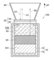
- FIG. 1 shows a radiant cooling device which is an example of the radiant cooling device of the present disclosure, in which an object to be cooled is accommodated in a heat insulating container, and the opening of the heat insulating container is upward (in the direction of arrow UP in FIG. 1; sky)
- UP in FIG. 1; sky
- the radiant cooling device 100 includes a heat insulating container 10.
- the heat insulating container 10 is a member for accommodating the object to be cooled 101 therein and thermally insulating the object to be cooled 101 from the outside.
- the heat insulating container 10 is formed by a container main body 12 and a container heat insulating member 14 disposed along the inner surface of the container main body 12. That is, the heat insulating container 10 is a composite member of the container main body 12 and the container heat insulating member 14. Of the container main body 12 and the container heat insulating member 14, at least the container heat insulating member 14 includes a heat insulating material.
- the container body 12 may or may not include a heat insulating material.
- the heat insulating container in the present disclosure is not limited to the composite member, and may be a single member including a heat insulating material.
- the container heat insulating member does not need to be disposed along the entire inner surface of the container body, and may be disposed only on a part of the inner surface.
- An opening 10 ⁇ / b> A is provided on the upper surface of the heat insulating container 10.
- the radiant cooling device 100 includes a far-infrared radiator 30 in the heat insulating container 10.
- the far-infrared radiator 30 emits a specific far-infrared ray 50.
- the far-infrared radiator 30 is disposed between the object to be cooled 101 and the opening 10 ⁇ / b> A.
- the far-infrared radiator 30 is in thermal contact with the object 101 to be cooled.
- the far-infrared radiator 30 is in direct contact with the object 101 or a thermally conductive member (for example, metal). Means contact via a member.
- the far-infrared radiator 30 is not necessarily fixedly disposed in the heat insulating container 10.
- the object to be cooled 101 is accommodated in the heat insulating container 10, it may be simply placed on the object to be cooled 101 directly or via a heat conductive member.
- the radiant cooling device 100 includes a far-infrared transmitting window member 20 that closes the opening 10 ⁇ / b> A of the heat insulating container 10.
- the far-infrared transmitting window member 20 is a member that covers the entire opening 10A of the heat insulating container 10, but the far-infrared transmitting window member is not limited to the form of the far-infrared transmitting window member 20.
- the far-infrared transmission window member may be a member that covers a part of the opening of the heat insulating container, or a member that is fitted into a part or the whole of the opening of the heat insulating container.
- the far infrared ray transmitting window member may be a member that closes at least a part of the opening of the heat insulating container.
- the far-infrared transmitting window member 20 is a composite member having a laminated structure in which a window member main body 22 and a sunlight reflecting layer 24 are laminated.
- the sunlight reflecting layer 24 is disposed on the upper side of the window member main body 22 (that is, on the side opposite to the far-infrared radiator 30 side when viewed from the window member main body 22).
- the sunlight reflecting layer 24 has a function of reflecting sunlight 51 (that is, electromagnetic waves having a wavelength range of 2.5 ⁇ m or less).
- the far-infrared transmitting window member 20 has a function of transmitting the specific far-infrared ray 50 emitted from the far-infrared radiator 30 as a whole.
- a far-infrared transmitting window member 20 that is a composite member, a far-infrared transmitting window member that is a single member having both a specific far-infrared transmitting function and a sunlight reflecting function may be used.
- the radiant cooling device 100 includes an intermediate heat insulating member 40 between the far infrared transmitting window member 20 and the far infrared radiator 30 in the heat insulating container 10.
- the intermediate heat insulating member 40 is a member for insulating the far-infrared transmitting window member 20 and the far-infrared radiator 30 and is a member that transmits the specific far-infrared ray 50 radiated from the far-infrared radiator 30.
- the heat insulating material of the intermediate heat insulating member 40 may be the same as or different from the heat insulating material of the container heat insulating member 14 described above. The heat insulating material will be described later.
- intermediate heat insulating member is a term for distinguishing from “container heat insulating member”. “Intermediate” means between the far-infrared transmitting window member and the far-infrared radiator.
- heat insulation means that heat conduction is suppressed, and there is no particular limitation on specific heat conductivity.
- the thermal conductivity of “heat insulation” in the present disclosure is preferably less than 0.1 W / (m ⁇ K), and more preferably 0.08 W / (m ⁇ K) or less.
- the specific far-infrared ray 50 radiated from the far-infrared radiator 30 that is in thermal contact with the cooled object 101 passes through the intermediate heat insulating member 40 and the far-infrared transmissive window member 20 in this order. It is discharged out of the radiant cooling device 100.
- the specific far-infrared ray 50 emitted to the outside of the radiation cooling apparatus 100 passes through the atmosphere without being absorbed by the atmosphere and reaches the sky (that is, outer space). As a result, the cooled object 101 is cooled by the radiation cooling phenomenon.
- the far-infrared radiator 30 is disposed in the heat insulating container 10. For this reason, heat inflow from the outside of the apparatus to the far-infrared radiator 30 is suppressed, and as a result, heat inflow to the cooled object 101 is also suppressed.
- the far-infrared transmitting window member 20 and the far-infrared radiator 30 are thermally insulated by the intermediate heat insulating member 40. For this reason, heat conduction from the far-infrared transmitting window member 20 to the far-infrared radiator 30 is suppressed, and as a result, heat conduction to the cooled object 101 is also suppressed.
- the radiant cooling device 100 since the above-described heat inflow and heat conduction are suppressed during cooling of the object to be cooled, the ultimate temperature can be lowered.
- the far-infrared transmission window member 20 including the solar light reflection layer 24 that reflects the sunlight 51 is used as the far-infrared transmission window member in the radiation cooling device 100, the temperature reached due to the heat of the sunlight 51. Rise is suppressed.
- a far-infrared transmitting window member that is a single member having both a specific far-infrared transmitting function and a sunlight reflecting function is used instead of the far-infrared transmitting window member 20 that is a composite member.
- the same effect as that obtained when the far-infrared transmitting window member 20 which is a composite member is used is produced.
- the arrangement angle of the entire radiant cooling device 100 is such that the opening 10A of the heat insulating container 10 faces directly above (that is, the direction opposite to the direction of gravity).
- the arrangement angle is not limited to this angle.
- the arrangement angle of the entire radiant cooling device 100 may be an arrangement in which the opening of the heat insulating container faces obliquely upward.
- the arrangement angle of the entire radiant cooling device 100 is such that the specific far-infrared ray 50 radiated from the far-infrared radiator 30 is radiated toward the sky via the intermediate heat insulating member 40 and the far-infrared transmitting window member 20. Any angle is acceptable.
- the arrangement angle of the entire radiation cooling device 100 is preferably an arrangement angle in which the opening of the heat insulating container faces in a direction different from the direction of the sun.
- the body to be cooled in the present disclosure (for example, the body to be cooled 101) is not particularly limited as long as it can be accommodated in the heat insulating container.
- the object to be cooled may be solid, liquid, or gas. From a practical point of view, the object to be cooled is preferably at least one of a solid and a liquid.
- the object to be cooled is a liquid, a container containing the liquid as the object to be cooled may be accommodated in the heat insulating container (see examples described later).
- the radiant cooling device of the present disclosure includes a heat insulating container (for example, the heat insulating container 10 described above).
- the heat insulating container is a container for accommodating a body to be cooled inside the heat insulating container and insulating the accommodated body to be cooled from the outside of the heat insulating container.
- the heat insulating container is not particularly limited as long as it can exhibit the above-described function. Even if the heat insulation container is a heat insulation container (for example, the above-mentioned heat insulation container 10) which is a composite member of a container main body (for example, the above-mentioned container main body 12) and a container heat insulation member (for example, the above-mentioned heat insulation container 14). It may be a composite member in which a metal film or the like is coated on the heat insulating material, or a heat insulating container that is a single member made of a heat insulating material.
- the preferable aspect of the heat insulating material contained in the container heat insulating member is the same as the preferable aspect of the heat insulating material included in the intermediate heat insulating member described later.
- the material of the container body of the heat insulating container is not particularly limited.
- a metal material or an inorganic material other than the metal material is preferable.
- the metal material include metals such as copper, silver, and aluminum; alloys such as stainless steel and aluminum alloys;
- the inorganic material other than the metal material include glass such as soda glass, potash glass, and lead glass; ceramics such as PLZT (lead lanthanum zirconate titanate titanate); quartz; fluorite; sapphire;
- a metal material having high performance of reflecting sunlight or radiant heat which is a main heat inflow source is preferable, and aluminum, silver, an aluminum alloy, or Stainless steel is more preferred.
- the material by which the metal material was coated with respect to inorganic materials other than a metal material may be sufficient.
- the wall thickness of the heat insulating container can be appropriately set in consideration of the strength of the heat insulating container, the degree of heat insulation, and the like.
- the heat insulating container is provided with openings (for example, the above-described opening 10A and an opening 110A described later).
- the opening part in a heat insulation container functions as an exit of the specific far infrared rays radiated
- the specific far-infrared rays emitted to the outside of the heat insulating container through the opening portion pass through the far-infrared transmitting window member, and further pass through the atmosphere to reach the sky.
- planar shape of the opening examples include an elliptical shape (including a circular shape), a rectangular shape (including a square shape), and a polygonal shape other than a rectangular shape.
- the shape of the opening in plan view may be an indefinite shape other than these shapes. From the viewpoint of ease of processing, the shape of the opening in plan view is preferably an elliptical shape, and more preferably a circular shape.
- the opening part in a heat insulation container may have a function as an entrance / exit of a to-be-cooled body.
- the entrance / exit of the to-be-cooled body may be provided in the heat insulation container separately from the opening.
- you may comprise a heat insulation container so that a to-be-cooled body can be put in a heat insulation container, or can be taken out from a heat insulation container.
- the object to be cooled does not have to be accommodated in the heat insulating container except when the object to be cooled is cooled. It can be said that a heat insulation container has a to-be-cooled body accommodating part.
- the cooled object may be housed and taken out from the cooled object housing portion, or may be fixed to the cooled body housing portion.
- a body-to-be-cooled body accommodating part may be a space provided with some support structure around it, for example, an internal space of some container.
- An insulating container provided with an opening, provided with a cooled object accommodating portion therein, and configured to be thermally insulated from the outside;
- a far-infrared radiator disposed between the object-to-be-cooled container and the opening in the heat insulating container, in thermal contact with the object to be cooled, and emitting far-infrared rays in the wavelength range of 8 ⁇ m to 13 ⁇ m;
- a far-infrared transmitting window member that closes at least part of the opening of the heat-insulating container and transmits the far-infrared radiation emitted from the far-infrared radiator;
- An intermediate heat insulating member that is disposed between the far infrared transmitting window member and the far infrared radiator, insulates the far infrared transmitting window member and the far infrared radiator, and transmits the far infrared radiation emitted from the far infrared radiator;
- a radiant cooling device comprising: Is provided.
- Such a radiant cooling device can be used to cool the member to be cooled by disposing the object to be cooled in the body to be cooled. For this reason, use of the radiant cooling device in cooling an object to be cooled is also provided.
- An insulating container provided with an opening, provided with a cooled object accommodating portion therein, and configured to be thermally insulated from the outside;
- a far-infrared radiator that emits far-infrared rays in the wavelength range of 8 ⁇ m to 13 ⁇ m;
- a far-infrared transmitting window member configured to transmit the far-infrared radiation emitted from the far-infrared radiator when arranged to close at least a part of the opening of the heat insulating container; Insulating the far-infrared transmitting window member and the far-infrared radiator when disposed between the far-infrared transmitting window member and the far-infrared radiator so that the far-infrared radiation radiated from the far-infrared radiator
- a configured intermediate heat insulating member The object to be cooled is arranged in the object to be cooled, and the far-infrared radiator is arranged between the object to be cooled and the opening in the heat insulating container so as to be in thermal contact with the object to be cooled.
- a process is described in which a heat insulating member is disposed between a far-infrared transmitting window member and a far-infrared radiator, and at least a part of the opening of the heat insulating container is closed by the far-infrared transmitting window member to cool the object to be cooled.
- a cooling kit is provided. Furthermore, use of such a cooling kit for cooling an object to be cooled is also provided.
- the height of the heat insulating container (that is, the length of the heat insulating container in the direction in which the specific far infrared ray is emitted from the far infrared emitter) is, for example, 10 mm to 2 m, preferably 10 mm to 500 mm, more preferably 100 mm to 300 mm.
- the maximum length of the heat insulating container (that is, the maximum length in the direction orthogonal to the height direction; for example, the diameter when the heat insulating container is cylindrical) is, for example, 10 mm to 30 m, and preferably 10 mm to 1000 mm.
- the thickness is preferably 100 mm to 500 mm.
- the maximum length of the opening of the heat insulating container (for example, the diameter when the opening is circular) is, for example, 10 mm to 30 m, preferably 10 mm to 1000 mm, more preferably 50 mm to 210 mm. Further, a plurality of openings may be provided for one heat insulating container.
- the radiation cooling device of the present disclosure includes a far-infrared radiator (for example, the above-described far-infrared radiator 30) that emits specific far-infrared rays in a heat insulating container.
- a far-infrared radiator for example, the above-described far-infrared radiator 30
- the far-infrared radiator is disposed between the object to be cooled and the opening of the heat insulating container and is in thermal contact with the object to be cooled.
- the position of the far-infrared radiator in the heat insulating container is a position where at least a part of the opening and at least a part of the far-infrared radiator overlap when the opening of the heat insulating container is viewed from the outside of the heat insulating container.
- the structure of the far-infrared radiator may be a single-layer structure including the radiator body, or may be a laminated structure including the radiator body and other layers (for example, a radiator reflecting layer described later). .
- the far-infrared radiator preferably has an average emissivity E 8-13 in the wavelength range of 8 ⁇ m to 13 ⁇ m in the direction of emitting specific far-infrared rays, preferably 0.80 or more, and more preferably 0.85 or more. 0.90 or more is particularly preferable.
- the average emissivity E 8-13 of the far-infrared radiator is 0.80 or more, the radiation performance of the specific far-infrared radiation of the far-infrared radiator is further improved, so that the temperature reached during cooling can be further lowered. .
- the average emissivity E 8-13 of the far-infrared transmitting window member is preferably 0.98 or less.
- the direction in which the specific far infrared ray is emitted is the direction in which the specific far infrared ray emitted from the far infrared radiator is emitted from the heat insulating container to the outside through the far infrared transmission window member. For example, in FIG. 1 and FIG. This is the direction indicated as the traveling direction of the far infrared ray 50.
- the preferable spectral characteristics (average emissivity) of the far-infrared radiator is, when the far-infrared radiator has a laminated structure, the spectrum of the entire far-infrared radiator (that is, the entire laminated structure). Means a characteristic.
- the average emissivity E 8-13 is determined by Kirchhoff's law at each of the wavelengths (the 10 wavelengths described above) included in the wavelength range of 8 ⁇ m to 13 ⁇ m in Appendix 3 of JIS R 3106: 1998. It means a value obtained by calculating the spectral emissivity from the spectral transmittance and the spectral reflectance and arithmetically averaging the obtained spectral emissivities. Specifically, the average emissivity in the wavelength range of 8 ⁇ m to 13 ⁇ m is obtained as follows. First, spectral transmittance and spectral reflectance in a wavelength range of 1.7 ⁇ m to 25 ⁇ m are measured by Fourier transform infrared spectroscopy (FTIR).
- FTIR Fourier transform infrared spectroscopy
- wavelengths included in the wavelength range of 8 ⁇ m to 13 ⁇ m in Appendix 3 of JIS R 3106: 1998 specifically, 8. 10 wavelengths of 1 ⁇ m, 8.6 ⁇ m, 9.2 ⁇ m, 9.7 ⁇ m, 10.2 ⁇ m, 10.7 ⁇ m, 11.3 ⁇ m, 11.8 ⁇ m, 12.4 ⁇ m, and 12.9 ⁇ m.
- Spectral emissivity is calculated from Kirchhoff's law.
- Spectral emissivity 1-Spectral transmittance-Spectral reflectivity "Average emissivity in the wavelength range of 8 ⁇ m to 13 ⁇ m" is obtained by arithmetically averaging the spectral emissivities (10 values) of each wavelength. .
- FTIR manufactured by Varian (model number: FTS-7000) was used as the FTIR apparatus.
- the far-infrared radiator preferably emits the specific far-infrared preferentially (ideally selectively) in the direction in which the specific far-infrared is radiated.
- the far infrared radiator is the ratio of the average emissivity E 8-13 to the average emissivity E 5-25 in the wavelength range of directions of 5 [mu] m ⁇ 25 [mu] m for emitting a specific far infrared E 8-13
- the / E 5-25 ratio is preferably 1.20 or more, more preferably 1.30 or more, and particularly preferably 1.50 or more.
- the E 8-13 / E 5-25 ratio of the far-infrared radiator is 1.20 or more, far-infrared radiation by atmospheric thermal radiation (that is, thermal radiation by an electromagnetic wave having a wavelength of less than 8 ⁇ m and an electromagnetic wave having a wavelength of more than 13 ⁇ m)
- a specific far-infrared ray can be emitted from the far-infrared radiator while suppressing heat inflow to the body. Accordingly, it is possible to lower the temperature reached during cooling.
- the E 8-13 / E 5-25 ratio is preferably 2.40 or less.
- the average emissivity E 5-25 means an arithmetic average value of spectral emissivities at wavelengths included in the wavelength range of 5 ⁇ m to 25 ⁇ m in Appendix 3 of JIS R 3106: 1998. Specifically, the average emissivity E 5-25 is obtained as follows. First, spectral transmittance and spectral reflectance in the wavelength range of 1.7 ⁇ m to 25 ⁇ m are measured by Fourier transform infrared spectroscopy (FTIR).
- FTIR Fourier transform infrared spectroscopy
- the spectral emissivity is calculated from Kirchhoff's law described above.
- the average emissivity E 5-25 is obtained by arithmetically averaging the spectral emissivities (24 values) of each wavelength.
- the average reflectance R 3-7 in the wavelength range of 3 ⁇ m to 7 ⁇ m of the surface on the far-infrared radiation window member side is preferably 0.05 or more, and preferably 0.10 or more. More preferred.
- the average reflectance R 3-7 of the far-infrared transmitting window member is 0.10 or more, the distance from the far-infrared radiator and the object to be cooled (the direction of the far-infrared emitting window member when viewed from the far-infrared radiator) is Since it is possible to suppress the incidence of electromagnetic waves in the wavelength range of 3 ⁇ m to 7 ⁇ m, it is possible to further suppress the increase in the temperature reached by the incidence of such electromagnetic waves.
- the average reflectance R 3-7 of 0.05 or more is more easily achieved when the far-infrared radiator includes a radiator reflecting layer described later. There is no particular upper limit on the average reflectance R 3-7 of the far-infrared transmitting window member. From the viewpoint of suitability for manufacturing the far-infrared transmitting window member, the average reflectance R 3-7 of the far-infrared transmitting window member is preferably 0.90 or less (more preferably 0.80 or less).
- the average reflectance R 3-7 means an arithmetic average value of spectral reflectances at wavelengths included in the wavelength range of 3 ⁇ m to 7 ⁇ m in Appendix Table 3 of JIS R 3106: 1998.
- the average reflectance R 3-7 is measured except that the spectral reflectance at a wavelength included in the wavelength range of 3 ⁇ m to 7 ⁇ m is measured in Table 3 of JIS R 3106: 1998, and the arithmetic average of the measurement results is obtained. This is the same as the method for measuring the average emissivity E 8-13 described above.
- a far-infrared radiator As a far-infrared radiator (radiator body), a substance that emits a specific far-infrared ray can be appropriately selected from known thermal radiators, and is not particularly limited.
- a black body radiator or a radiator including a laminated film of a titania film and a silica film is preferable in that the average emissivity in the wavelength range of 8 ⁇ m to 13 ⁇ m is high.
- a black-body radiator is preferable from the viewpoint of manufacturability.
- Blackbody radiators include blackbody radiators that are black bodies themselves, blackbody radiators that have a commercially available blackbody spray applied to the surface of a metal material, and black bodies that have a commercially available blackbody tape attached to the surface of a metal material. And radiators.
- the far-infrared radiator Radiator body
- E 8-13 / E 5-25 ratio e.g., E 8-13 / E 5-25 ratio is 1.20 or more
- a radiator including a laminated film of a titania film and a silica film is preferable.
- the three-dimensional shape of the entire far-infrared radiator is not particularly limited, but is preferably a plate shape from the viewpoint of making the apparatus compact.
- plan view shape of the entire far-infrared radiator There is no particular limitation on the plan view shape of the entire far-infrared radiator.
- Examples of the shape of the far-infrared radiator in plan view include an elliptical shape (including a circular shape), a rectangular shape (including a square shape), and a polygonal shape other than a rectangular shape.
- the shape of the far-infrared radiator in plan view may be an indefinite shape other than these shapes.
- the planar shape of the entire far-infrared radiator is preferably an elliptical shape, particularly preferably a circular shape, from the viewpoint of availability.
- the thickness of the entire far-infrared radiator is preferably 1 mm to 30 mm, more preferably 1 mm to 20 mm, and particularly preferably 2 mm to 10 mm.
- the thickness of the entire far-infrared radiator is 1 mm or more, it is advantageous in terms of the strength of the far-infrared radiator.
- the thickness of the far-infrared radiator is 30 mm or less, it is advantageous in terms of space saving in the heat insulating container.
- the far-infrared radiator can include a radiator body and a radiator reflecting layer that is disposed on the far-infrared radiation window member side as viewed from the radiator body and reflects electromagnetic waves in a wavelength region of 3 ⁇ m to 7 ⁇ m.
- the far-infrared radiator includes the radiator reflecting layer, the wavelength region of 3 ⁇ m to 7 ⁇ m from above the radiator body and the cooled object (in the direction of the far-infrared radiation window member when viewed from the far-infrared radiator). Since the incidence of electromagnetic waves can be suppressed, an increase in the arrival temperature due to the incidence of such electromagnetic waves can be further suppressed.
- the preferable aspect of a radiator reflective layer is the same as the preferable aspect of the below-mentioned sunlight reflective layer. According to the aspect in which the far-infrared radiator includes the radiator reflecting layer, it is easier to achieve that the average reflectance R 3-7 of the far-infrared radiator is 0.05 or more.
- the radiant cooling device of the present disclosure includes a far-infrared transmitting window member (for example, the far-infrared transmitting window member 20 described above) that transmits a specific far-infrared ray (that is, a far-infrared ray having a wavelength range of 8 ⁇ m to 13 ⁇ m).
- the far-infrared transmitting window member is disposed so as to close at least a part of the opening of the heat insulating container. From the viewpoint of lowering the ultimate temperature during cooling, the far-infrared transmitting window member is preferably arranged so as to close the entire opening of the heat insulating container.
- the structure of the far-infrared transmitting window member may be a single-layer structure including a window member main body, or may be a laminated structure including a window member main body and other layers (for example, a solar reflective layer described later). Good.
- the far-infrared transmission window member preferably has an average transmittance T 8-13 in the wavelength range of 8 ⁇ m to 13 ⁇ m in the direction of transmitting the specific far-infrared ray is 0.40 or more, more preferably 0.50 or more. Preferably, it is 0.60 or more.
- the direction of transmitting the specific far-infrared is the direction in which the specific far-infrared emitted from the far-infrared radiator is emitted from the heat insulating container to the outside through the far-infrared transmitting window member. For example, in FIG. 1 and FIG.
- the average transmittance T 8-13 of the far-infrared transmitting window member is 0.40 or more, the specific far-infrared ray radiated from the far-infrared radiator is more easily transmitted through the far-infrared transmitting window member. The reached temperature can be further lowered.
- the upper limit of the average transmittance T 8-13 of the far infrared ray transmitting window member is no particular limitation on the upper limit of the average transmittance T 8-13 of the far infrared ray transmitting window member. From the viewpoint of suitability for manufacturing the far-infrared transmitting window member, the average transmittance T 8-13 of the far-infrared transmitting window member is preferably 0.98 or less.
- preferable spectral characteristics (average transmittance and solar reflectance) of the far-infrared transmitting window member are the entire far-infrared transmitting window member when the far-infrared transmitting window member has a laminated structure ( That is, it means the spectral characteristics of the entire laminated structure).
- the average transmittance T 8-13 means an arithmetic average value of spectral transmittances at wavelengths included in the wavelength range of 8 ⁇ m to 13 ⁇ m in Appendix Table 3 of JIS R 3106: 1998.
- the average transmittance T 8-13 is obtained as follows. First, spectral transmittance in the wavelength range of 1.7 ⁇ m to 25 ⁇ m is measured by Fourier transform infrared spectroscopy (FTIR). Among the measurement results of the spectral transmittance in the wavelength range of 1.7 ⁇ m to 25 ⁇ m, the spectrum at the wavelengths (the aforementioned 10 wavelengths) included in the wavelength range of 8 ⁇ m to 13 ⁇ m in Appendix 3 of JIS R 3106: 1998. The average transmittance T 8-13 is obtained by arithmetically averaging the transmittance values (that is, 10 values).
- the far-infrared transmitting window member preferably transmits the specific far-infrared light preferentially (ideally selectively) in the direction in which the specific far-infrared light is transmitted.
- the far-infrared transmitting window member has a ratio T 8 ⁇ that is the ratio of the average transmittance T 8-13 to the average transmittance T 5-25 in the wavelength range of 5 ⁇ m to 25 ⁇ m in the direction of transmitting the specific far infrared rays.
- the 13 / T 5-25 ratio is preferably 1.20 or more, more preferably 1.30 or more, and particularly preferably 1.50 or more.
- the T 8-13 / T 5-25 ratio of the far-infrared transmitting window member is 1.20 or more, radiation cooling by atmospheric thermal radiation (that is, thermal radiation by an electromagnetic wave having a wavelength of less than 8 ⁇ m and an electromagnetic wave having a wavelength of more than 13 ⁇ m)
- the specific far-infrared ray from the far-infrared radiator can be transmitted while suppressing the heat inflow into the apparatus. Accordingly, it is possible to lower the temperature reached during cooling.
- the T 8-13 / T 5-25 ratio is preferably 2.40 or less.
- the average transmittance T 5-25 means an arithmetic average value of spectral transmittances at wavelengths included in the wavelength range of 5 ⁇ m to 25 ⁇ m in Appendix Table 3 of JIS R 3106: 1998. Specifically, the average transmittance T 5-25 is determined as follows. First, spectral transmittance in the wavelength range of 1.7 ⁇ m to 25 ⁇ m is measured by Fourier transform infrared spectroscopy (FTIR). Among the measurement results of the spectral transmittance in the wavelength range of 1.7 ⁇ m to 25 ⁇ m, the wavelengths included in the wavelength range of 5 ⁇ m to 25 ⁇ m in Appendix Table 3 of JIS R 3106: 1998 (that is, the aforementioned 24 wavelengths). The average transmittance T 5-25 is obtained by arithmetically averaging the spectral transmittance values (ie, 24 values).
- FTIR Fourier transform infrared spectroscopy
- the far-infrared transmitting window member preferably has a solar reflectance of 60% or more on the surface opposite to the surface on the far-infrared radiator side.
- the solar radiation reflectance of the far-infrared transmitting window member is 60% or more, it is possible to suppress the incidence of sunlight (that is, electromagnetic waves having a wavelength range of 300 nm to 2500 nm) into the heat insulating container. Heat inflow can be suppressed. Accordingly, it is possible to lower the temperature reached during cooling.
- the solar reflectance of the far infrared ray transmitting window member is more preferably 70% or more, and particularly preferably 80% or more.
- the solar reflectance of the far-infrared transmitting window member is preferably 98% or less. It is easy to achieve that the far-infrared transmission window member has a solar reflectance of 60% or more when the far-infrared transmission window member includes a solar light reflection layer described later.
- the solar reflectance refers to a value calculated based on the diffuse reflectance obtained by measuring the diffuse reflectance with a spectrophotometer in accordance with JIS A 5759: 2008.
- a spectrophotometer is used as the spectrophotometer.
- a spectrophotometer V-670 integrated sphere spectrophotometer manufactured by JASCO was used as a spectrophotometer used for measurement of solar reflectance.
- the material of the far infrared ray transmitting window member (window member main body) is not particularly limited as long as it is a material that can transmit the specific far infrared ray.
- Examples of the material of the far-infrared transmission window member (window member main body) include metal materials, inorganic materials other than metal materials, and more specifically, germanium (Ge; transmission wavelength: 1.8 ⁇ m to 23 ⁇ m), chalcogenide (Transmission wavelength: 0.75 ⁇ m to 14 ⁇ m), silicon (Si; transmission wavelength: 1.2 ⁇ m to 15 ⁇ m), diamond (transmission wavelength: 220 nm or more), calcium fluoride (CaF 2 ; transmission wavelength: 0.12 ⁇ m to 12 ⁇ m), zinc selenium (ZnSe) Transmission wavelength 0.5 ⁇ m to 22 ⁇ m), barium fluoride (BaF 2 ; transmission wavelength 0.15 ⁇ m to 15 ⁇ m), zinc sulfide (ZnS; transmission
- the three-dimensional shape of the entire far-infrared transmitting window member is preferably a plate shape.
- the shape of the far-infrared transmitting window member in plan view.
- Examples of the planar shape of the entire far-infrared transmitting window member include an elliptical shape (including a circular shape), a rectangular shape (including a square shape), and a polygonal shape other than a rectangular shape.
- the far-infrared transmission window member may have an indefinite shape other than these shapes in plan view.
- the thickness of the entire far-infrared transmitting window member is preferably 1 mm to 30 mm, more preferably 1 mm to 20 mm, and particularly preferably 2 mm to 10 mm.
- the thickness is 1 mm or more, the penetration of electromagnetic waves other than the specific far-infrared ray into the heat insulating container can be further suppressed, and the strength of the far-infrared transmitting window member is advantageous.
- the thickness is 30 mm or less, the transmittance of the specific far infrared ray is further improved.
- the far-infrared transmissive window member can include a window member main body and a sunlight reflecting layer that is disposed on the side opposite to the far-infrared radiator side when viewed from the window member main body and reflects sunlight.
- the far-infrared transmitting window member includes the sunlight reflecting layer, it is possible to suppress the incidence of sunlight (that is, electromagnetic waves having a wavelength range of 0.3 ⁇ m to 2.5 ⁇ m) into the heat insulating container. Heat inflow can be suppressed. Accordingly, it is possible to lower the temperature reached during cooling.
- the solar reflectance of the far-infrared transmitting window member is 60% or more (preferably 70% or more, more preferably 80% or more. Is easier to achieve).
- the sunlight reflecting layer has a function of reflecting sunlight, but may have a function of reflecting electromagnetic waves other than sunlight (for example, electromagnetic waves having a wavelength of more than 2.5 ⁇ m and less than 8 ⁇ m).
- the structure of the sunlight reflecting layer may be a single layer structure or a laminated structure.
- the laminated structure is preferably a laminated structure having at least one layer selected from the group consisting of a metal layer, an inorganic layer, and an organic layer.
- the structure of the sunlight reflecting layer may be a structure including a minute structure (particles, bubbles, etc.), or may be a structure having an uneven structure on the surface.
- Examples of the “micro structure” in the case where the structure of the sunlight reflecting layer includes a micro structure include particles, bubbles, and the like.
- a sunlight reflective layer is not limited to being a continuous layer, The particle layer which consists of the particle
- the solar reflective layer preferably contains particles.
- the number average particle diameter of the particles is preferably 0.1 ⁇ m to 20 ⁇ m.
- the scattering cross section for sunlight of the sunlight reflecting layer increases. Thereby, the solar radiation reflectance of the whole far-infrared transmission window member can be enlarged more.
- the scattering cross section for the specific far-infrared ray of the sunlight reflecting layer becomes small. Thereby, the transmittance
- the number average particle diameter of the particles means a value measured as follows. That is, the solar reflective layer is cut along the thickness direction using a microtome, and a cross-sectional image at a magnification of 1000 is obtained from the cut surface using an electron microscope S4100 (manufactured by Hitachi High-Technology Corporation). In the acquired cross-sectional image, in each particle, the maximum length among the line segments connecting the two points inside the particle is defined as the particle length. The measurement of the above particle length is performed about 100 places in a cross-sectional image, and let the average value of 100 measured values be the number average particle diameter of particles.
- substances constituting the particles include titanium oxide, barium titanate compound, zinc sulfide, barium oxide, magnesium oxide, calcium oxide, and the like.
- zinc sulfide is preferable in terms of excellent optical characteristics.
- the solar reflective layer may contain a resin.
- Specific examples of the resin are the same as the specific examples of the resin in the resin layer containing bubbles, which will be described later.
- the solar reflective layer is composed of particles dispersed in the window member body (for example, zinc sulfide particles, titanium oxide particles) from the viewpoint of maintaining the transmission of specific far infrared rays as the entire far infrared transparent window member. Etc.) is preferable.
- the material other than the bubbles includes a resin. That is, as the sunlight reflecting layer, a sunlight reflecting layer that is a resin layer containing bubbles can also be used.
- the resin in the resin layer containing bubbles include polyolefin (for example, polyethylene, polypropylene, poly-4-methylpentene-1, polybutene-1, etc.), polyester (for example, polyethylene terephthalate, polyethylene naphthalate, etc.), polycarbonate, polyvinyl chloride.
- polyester is preferable from the viewpoint of excellent processability and optical characteristics, and polyethylene terephthalate (hereinafter also referred to as “PET”) is preferable.
- the resin layer containing bubbles may contain a mixture of two or more kinds of resins depending on the purpose. Moreover, the resin layer containing air bubbles may contain inevitable impurities as long as it does not affect the reflectance of sunlight.
- the bubble in the resin layer containing bubbles refers to a space made of a gas having a bubble length of 10 nm or more present in the resin.
- the bubble length refers to the maximum length of line segments connecting two points inside the bubble in each bubble.
- the bubble length is a value measured by the method described later.
- the type of gas may be air, or may be another type of gas other than air, such as oxygen, nitrogen, carbon dioxide.
- the shape of the bubble is not particularly limited, and examples thereof include various shapes such as a spherical shape, a cylindrical shape, an elliptical shape, a rectangular parallelepiped shape (cubic shape), and a prismatic shape.
- atmospheric pressure may be sufficient as the pressure of gas, and it may be pressurized or pressure-reduced rather than atmospheric pressure.
- Each of the bubbles may be present in isolation or may be partially connected.
- the number average length of the bubbles is preferably 0.1 ⁇ m to 20 ⁇ m.
- the scattering cross-sectional area of the sunlight reflecting layer with respect to sunlight increases. Thereby, the solar reflectance of a far-infrared transmissive window member can be enlarged more.
- the scattering cross section for the specific far infrared ray of the sunlight reflecting layer becomes small. Thereby, the transmittance
- the number average length of the bubbles means a value measured as follows. In the cross-sectional image obtained in the same manner as in the measurement of the number average particle diameter of the particles, the maximum length of the line segments connecting two points inside the bubbles is defined as the bubble length. The above bubble length measurement is performed for 100 bubbles in the cross-sectional image, and the average value of the 100 measured values is taken as the number average length of the bubbles.
- a commercially available resin film can also be used as a sunlight reflective layer which is a resin layer containing air bubbles.
- Commercially available resin films include Furukawa Electric Co., Ltd. ultra-fine foamed light reflector “MCPET / MCPOLYCA”, Toray Industries white PET film, Lumirror (registered trademark) E20, E22, E28G, The E60 can be mentioned.
- a concavo-convex structure in the case where the structure of the sunlight reflecting layer has a concavo-convex structure on the surface, a concavo-convex structure having an average pitch of 100 ⁇ m or less is preferable.
- means for forming such a concavo-convex structure include nanoimprint and plasma etching.
- the radiation cooling device of this indication is provided with an intermediate heat insulation member between a far-infrared transmitting window member and a far-infrared radiator in a heat insulation container.
- the intermediate heat insulating member insulates the far-infrared transmitting window member and the far-infrared radiator and transmits specific far-infrared light.
- the intermediate heat insulating member preferably has an average transmittance T 8-13 in the wavelength range of 8 ⁇ m to 13 ⁇ m in the direction of transmitting the specific far infrared ray of 0.50 or more.
- the meaning of the average transmittance T 8-13 is as described above.
- the intermediate heat insulating member is a member that scatters against the specific far infrared ray
- the average transmittance T 8-13 of the intermediate heat insulating member is 0.50 or more
- the specific far infrared ray is radiated and cooled.
- the intermediate heat insulating member is effectively transmitted as energy.
- the average transmittance T 8-13 of the intermediate heat insulating member is more preferably 0.60 or more, more preferably 0.70 or more, and 70% from the viewpoint of lowering the ultimate temperature during cooling. The above is particularly preferable.
- the average transmittance T 8-13 of the intermediate heat insulating member is preferably 0.98 or less from the viewpoint of suitability for manufacturing a far-infrared radiator.
- the intermediate heat insulating member preferably has a solar reflectance of 60% or more on the far infrared absorbing window member side surface.
- the solar reflectance of the intermediate heat insulating member is more preferably 70% or more, and particularly preferably 80% or more.
- the solar reflectance of the far infrared ray transmitting window member is preferably 98% or less.
- the solar reflectance of the far-infrared transmitting window member is 60% or more
- the solar reflectance of the intermediate heat insulating member is 60% or more. The same effect as the case can be obtained.
- the method for measuring solar reflectance is as described above.
- the intermediate heat insulating member preferably has a thermal conductivity in the direction in which the specific far-infrared ray is transmitted of 0.08 W / (m ⁇ K) or less, and more preferably 0.06 W / (m ⁇ K) or less. .
- the thermal conductivity of the intermediate heat insulating member is 0.08 W / (m ⁇ K) or less, heat conduction from the far-infrared transmitting window member to the far-infrared radiator is further suppressed.
- the thermal conductivity of the intermediate heat insulating member is preferably 0.001 W / (m ⁇ K) or more.
- the thermal conductivity of the intermediate heat insulating member in the direction in which the specific far-infrared ray is transmitted means a value measured according to JIS A 1412-2.
- the intermediate heat insulating member preferably contains at least one resin as a heat insulating material from the viewpoint of a heat insulating effect.
- the resin that can be contained in the intermediate heat insulating member is preferably at least one selected from the group consisting of polyethylene, polypropylene, polycarbonate, polystyrene, and polynorbornene from the viewpoint of the heat insulating effect.
- the resin that can be contained in the intermediate heat insulating member preferably includes polyethylene, more preferably polyethylene, from the viewpoint of processability.
- the intermediate heat insulating member may include a mixture of two or more kinds of resins depending on the purpose. Further, the intermediate heat insulating member may contain inevitable impurities as long as it does not affect the transmittance of the specific far infrared ray.
- the resin that can be contained in the intermediate heat insulating member preferably contains bubbles from the viewpoint of the heat insulating effect.
- the heat insulating effect of the entire intermediate heat insulating member is further enhanced by the bubbles (that is, the space) having a high heat insulating effect.
- the bubble in the resin that can be contained in the intermediate heat insulating member refers to a space made of a gas having a bubble length of 10 nm or more present in the resin.
- the bubble length refers to the maximum length of line segments connecting two points inside the bubble in each bubble.
- the bubble length is a value measured by the method described later.
- the type of gas may be air, or may be another type of gas other than air, such as oxygen, nitrogen, carbon dioxide.
- the shape of the bubble is not particularly limited, and examples thereof include various shapes such as a spherical shape, a cylindrical shape, an elliptical shape, a rectangular parallelepiped shape (cubic shape), and a prismatic shape.
- atmospheric pressure may be sufficient as the pressure of gas, and it may be pressurized or pressure-reduced rather than atmospheric pressure.
- Each of the bubbles may be present in isolation or may be partially connected.
- the porosity of the intermediate heat insulating member is preferably 70% or more.
- the porosity of the intermediate heat insulating member is 70% or more, the ratio of heat conduction through the air in the heat conduction of the entire intermediate heat insulating member is increased, so that the heat insulating effect of the entire intermediate heat insulating member is further enhanced. Further, for the above reason, 80% or more is preferable, and 90% or more is more preferable.
- the porosity of the intermediate heat insulating member is preferably 98% or less.
- the porosity of the intermediate heat insulating member is a value measured as follows.
- the intermediate heat insulating member is cut along the transmission direction of the specific far-infrared ray using a microtome, and a cross-sectional image with a magnification of 10 times is acquired for the obtained cross section using a Nikon optical microscope ME600L.
- the area a of the part corresponding to the bubbles and the area b of the part other than the bubbles are respectively measured, and the porosity of the heat insulating layer is obtained by the following calculation formula.
- Porosity of heat insulation layer (%) (area a / (area a + area b)) ⁇ 100
- the porosity is calculated using a cross-sectional image corresponding to a real area of 500 mm 2 for the cross section of the heat insulating layer.
- the number of bubbles crossed by the straight line in the transmission direction is preferably 8 or less in the cross section obtained by cutting the intermediate heat insulating member along the transmission direction of the specific far infrared ray. The following is more preferable. If the number of the bubbles is 8 or less, the average transmittance T 8-13 of the intermediate heat insulating member can be easily improved, so that the temperature reached during cooling becomes lower. Specifically, since the refractive index of the resin is often about 1.5 in the far-infrared region, the far-infrared lost by reflection at the interface between the resin and the bubbles is about 4%.
- the lower limit of the number of bubbles can be 1 or more, and 2 or more is preferable.
- the number of the bubbles means a value measured as follows. In a cross-sectional image obtained by the same method as in the measurement of the porosity of the intermediate heat insulating member, a straight line in the transmission direction of the specific far infrared ray is drawn, and the number of bubbles crossed by this straight line is measured (counted). The above measurement is performed at 100 locations in the cross-sectional image, and the average value of 100 measured values is defined as the number of bubbles.
- the number average length of the bubbles is preferably 1 mm or more.
- the number average length of the bubbles is more preferably 1 mm to 50 mm, still more preferably 1 mm to 30 mm, and particularly preferably 1 mm to 20 mm. .
- the number average length of the bubbles means a value measured as follows. In a cross-sectional image acquired by the same method as that used for measuring the porosity of the intermediate heat insulating member, the maximum length of the line segments connecting two points inside the bubble is defined as the bubble length. The above bubble length measurement is performed for 100 bubbles in the cross-sectional image, and the average value of the 100 measured values is taken as the number average length of the bubbles.
- a bubble cushioning material may be mentioned.
- Commercially available foam cushioning materials include Air Cap (registered trademark) (Sakai Chemical Industry Co., Ltd.), Petit Petit (registered trademark) (Kawakami Sangyo Co., Ltd.), Minapak (registered trademark) (Sakai Chemical Industry Co., Ltd.), etc. Can be mentioned.
- the number average length of the bubbles is preferably 1 ⁇ m or less.
- the number average length of the bubbles is more preferably 0.1 ⁇ m to 1 ⁇ m.
- the radiation cooling device of this indication may be provided with other members other than the member mentioned above. Examples of other members are shown below, but the other members are not limited to the following examples.
- the radiant cooling device of the present disclosure may include a container outer reflection film that reflects sunlight on the outer side of at least a part of the outer surface of the heat insulating container. Thereby, since heat_generation
- the external reflection film a layer similar to the above-described solar reflective layer (preferably, a solar reflective layer that is a resin layer containing bubbles) can be used.
- the radiant cooling device of the present disclosure may include an internal far-infrared reflective film that is disposed along the inner surface of the heat insulating container and reflects far-infrared rays (electromagnetic waves in a wavelength region of 5 ⁇ m to 25 ⁇ m).
- the internal far-infrared reflective film may be disposed between the inner surface of the heat insulating container and the far-infrared radiator and the object to be cooled.
- the internal far-infrared reflective film may be in contact with at least a part of the inner surface of the heat insulating container or may not be in contact with it.
- “inside” in the internal far-infrared reflective film means the inside of the heat insulating container.
- the radiation cooling device of the present disclosure includes the internal far-infrared reflective film, heat radiation from the heat insulating container to the object to be cooled can be suppressed, so that the temperature reached during cooling can be further reduced.
- the internal far-infrared reflective film has an average reflectance R 5-25 in the wavelength region of 5 ⁇ m to 25 ⁇ m of preferably 0.40 or more, more preferably 0.60 or more, and 0.80 or more. It is particularly preferred.
- the average reflectance R 5-25 means an arithmetic average value of spectral reflectances at wavelengths included in the wavelength range of 5 ⁇ m to 25 ⁇ m in Appendix Table 3 of JIS R 3106: 1998.
- the average reflectance R 5-25 is measured except that the spectral reflectance at a wavelength included in the wavelength range of 5 ⁇ m to 25 ⁇ m is measured in Table 3 of JIS R 3106: 1998, and the arithmetic average of the measurement results is obtained. This is the same as the method for measuring the average transmittance T 8-13 .
- Examples of the material for the internal far-infrared reflective film include aluminum, aluminum alloy, silver, silver alloy, copper, and copper alloy.
- the radiant cooling device of the present disclosure may include a metal cylinder member through which specific far-infrared rays that have passed through the far-infrared transmitting window member pass on the side opposite to the opening of the heat insulating container as viewed from the far-infrared transmitting window member.
- a metal cylinder member through which specific far-infrared rays that have passed through the far-infrared transmitting window member pass on the side opposite to the opening of the heat insulating container as viewed from the far-infrared transmitting window member.
- cylinder is a concept including a tapered cylinder.
- a taper cylinder refers to a cylinder having a shape in which the diameter (outer diameter and inner diameter) increases from one axial end to the other.
- FIG. 2 is a schematic cross-sectional view of a radiant cooling device including a metal cylinder member, which is another example of the radiant cooling device of the present disclosure.
- the structure of the radiant cooling device 150 shown in FIG. 2 is the same as the structure of the radiant cooling device 100 shown in FIG. 1 except that the metal cylinder member 60 is provided.
- the radiant cooling device 150 includes a metal cylinder member 60 on the side opposite to the opening 10 ⁇ / b> A of the heat insulating container 10 when viewed from the far infrared ray transmission window member 20.
- the metal cylinder member 60 has a tapered cylinder shape. Examples of the shape of the tapered cylinder include a linear tapered shape, a parabolic tapered shape, and an exponential tapered shape.
- the metal cylinder member 60 is disposed so that one end in the axial direction is in contact with the far-infrared transmitting window member 20 and the diameter increases in the direction from one end to the other end in the axial direction. Furthermore, the metal cylinder member 60 includes the opening 10A within a range surrounded by the inner peripheral surface on one end side of the metal cylinder member 60 in a plan view (not shown) viewed from the opening direction of the opening 10A.
- the radiant cooling device 150 heat from the surrounding environment member (for example, a building such as a building or a utility pole) is passed through the inside of the metal cylinder member 60 while the specific far infrared ray 50 that has passed through the far infrared ray transmission window member 20 is passed through. Radiation (specifically, far infrared rays radiated from the surrounding environment member) can be blocked by the outer peripheral surface of the metal cylinder member 60. Furthermore, since the metal cylinder member 60 is arranged in such a direction that the diameter increases as it goes from one end to the other end in the axial direction, the effective area from which the specific far-infrared ray 50 is emitted is larger than the area of the opening 10A. growing. For these reasons, the radiant cooling device 150 can achieve better cooling performance, so that the ultimate temperature can be lowered.
- the surrounding environment member for example, a building such as a building or a utility pole
- the opening area of the other end side in the axial direction of the metal cylinder member 60 (that is, the end portion far from the far-infrared transmitting window member 20) is from the viewpoint of increasing the effective area from which the specific far-infrared ray 50 is emitted.
- the area of the opening 10A is preferably 1.1 times or more, and more preferably 1.3 times or more.
- the opening area on the other end side in the axial direction of the metal cylinder member 60 is preferably 6.0 times or less with respect to the area of the opening 10A from the viewpoint of more effectively blocking heat radiation from the surrounding environment member. 0.0 times or less is more preferable.
- a metal having a high far-infrared reflectance is preferable, and specifically, aluminum, an aluminum alloy, silver, or a silver alloy is preferable.
- the metal cylinder member As the metal cylinder member, a commercially available parabolic mirror (for example, a parabolic mirror manufactured by Kokusai Shoji Co., Ltd.) may be used.
- the parabolic mirror parabolic mirror refers to a metal cylinder member having a parabolic taper shape.
- the radiant cooling device of the present disclosure includes the above-described metal cylinder member
- the radiant cooling device of the present disclosure has an angle at which the outer opening of the metal cylinder member (the end on the side far from the far-infrared transmitting window member) faces. You may provide the angle changing apparatus to change.
- the outer opening of the metal tube member refers to the opening at the end on the side far from the far-infrared transmitting window member.
- This angle changing device preferably has a function of directing the outer opening of the metal cylinder member in a direction different from the position of the sun. In order to realize such a function, any system can be appropriately selected and applied.
- the direct opening of the sun can be suppressed by directing the outer opening of the metal tube member in a direction different from the position of the sun, so that heat inflow due to this incident can be suppressed. Thereby, especially the rise of the ultimate temperature in the daytime can be suppressed more.
- Example 1 ⁇ Production of radiation cooling device>
- the radiant cooling device shown in FIG. 3 was produced.
- FIG. 3 is a schematic cross-sectional view conceptually showing the radiant cooling device 200 of the first embodiment.
- the production of the radiation cooling apparatus 200 will be described with reference to FIG.
- a container 112 container body made of SUS304 having a shape in which an opening 110A of ⁇ 140 mm was provided on the upper surface of an inner hollow cylindrical shape having an inner diameter ⁇ 200 mm, an outer diameter ⁇ 220 mm, and a height 168 mm was prepared.
- SUS304 is a kind of stainless steel.
- a cup-shaped SUS304 container 116 (container body) having a diameter of 65 mm and a height of 40 mm was prepared, and 50 mL of water 201 serving as an object to be cooled was accommodated in the container 116.
- a container 116 containing water 201 (that is, an object to be cooled) was placed in the container 112, and a container heat insulating member 114 was filled between the containers 112 and 116.
- the heat insulating container 110 is formed by the container 112 (container main body), the container heat insulating member 114, and the container 116 (container main body).
- a bubble cushioning material made of polyethylene containing bubbles with a number average length of 10 mm (Puchipuchi (registered trademark), product name d42, manufactured by Kawakami Sangyo Co., Ltd.) was used.
- a black body paint (Japan Sensor Co., Ltd., black body paint JSC-3) was applied to the surface of a disk made of SUS304 having a diameter of 70 mm and a thickness of 5 mm, and dried to produce a far-infrared radiator 130.
- the entire opening of the container 116 was covered with the far-infrared radiator 130 to which the radiation fins 132 were attached.
- the radiating fins 132 were brought into contact with the water 201 (cooled body) in the container 116. Thereby, the far-infrared radiator 130 and the water 201 (cooled body) were brought into thermal contact.
- the space inside the container 112 and above the far-infrared radiator 130 is filled with the intermediate heat insulating member 140, and then the entire opening 110A of the container 112 is used as the window member body of the far-infrared transmitting window member.
- the Ge window member 120 was covered.
- the intermediate heat insulating member 140 a polyethylene bubble heat insulating material containing bubbles having a number average length of 10 mm (Puchipuchi (registered trademark), product name d42, manufactured by Kawakami Sangyo Co., Ltd.) was used.
- a polyethylene bubble heat insulating material containing bubbles having a number average length of 10 mm (Puchipuchi (registered trademark), product name d42, manufactured by Kawakami Sangyo Co., Ltd.) was used.
- transmission direction of a far-infrared ray it has arrange
- Ge window member 120 a 5 mm-thick germanium plate (manufactured by IR System) having a DLC (diamond-like carbon) coating on both sides was used.
- DLC diamond-like carbon
- Example 1 a white void film (Toray Industries Inc., Lumirror (registered trademark) E60) (not shown: external reflection film) was attached to the entire outer surface of the container 112. Thus, the radiant cooling device 200 of Example 1 was obtained.
- a white void film Toray Industries Inc., Lumirror (registered trademark) E60
- each member was as shown in Table 1.
- each physical property of the intermediate heat insulating member is as shown in Table 1.
- the radiant cooling device 200 produced above was installed outdoors at an arrangement angle at which the opening 110A of the heat insulating container 110 faces directly above. As an outdoor location, a location where there is no object that blocks the specific far-infrared rays emitted from the far-infrared radiator 130 toward the sky was selected. After 6 hours from the installation, the temperature difference (° C.) shown in the following formula was measured to evaluate the ultimate temperature during cooling.
- Temperature difference (° C.) Temperature (° C.)-Outside air temperature (° C.) of water 201 in the radiant cooling device 200 (that is, a cooled object)
- the negative temperature difference (° C.) and the larger the absolute value means that the ultimate temperature during cooling is lower. Needless to say, when the temperature difference (° C.) is negative, the ultimate temperature during cooling is lower than when the temperature difference (° C.) is positive.
- the temperature reached during cooling was evaluated during the daytime when the weather was clear. The results are shown in Table 1.
- Example 2 In the production of a radiant cooling device, sunlight reflection made of zinc sulfide particles is made by dispersing zinc sulfide particles having a number average particle size of 0.2 ⁇ m on the upper surface of the Ge window member 120 (that is, the surface that comes into contact with the outside air).
- a radiation cooling device was produced in the same manner as in Example 1 except that the layer was formed. Evaluation similar to Example 1 was performed using the obtained radiation cooling apparatus. The results are shown in Table 1.
- Example 1 In the production of the radiant cooling device, the radiant cooling device was produced in the same manner as in Example 1 except that the intermediate heat insulating member 140 was not used. Evaluation similar to Example 1 was performed using the obtained radiation cooling apparatus. The results are shown in Table 1.
- Example 1 As shown in Table 1, in the daytime evaluation at the time of fine weather, in the radiant cooling device of Examples 1 and 2 including the intermediate heat insulating member, compared with the radiant cooling device of Comparative Example 1 not including the intermediate heat insulating member, The temperature reached during cooling was low. Specifically, in Example 1, the temperature reached during cooling was 1.1 ° C. lower than that of Comparative Example 1, and in Example 2, the temperature reached during cooling was 6.9 ° C. lower than that of Comparative Example 1. . In contrast to Examples 1 and 2, the radiation cooling device of Example 2 in which the infrared reflectance of the infrared transmitting window member is 80% or more was particularly excellent in the effect of lowering the temperature reached during cooling in the daytime. .
Landscapes
- Engineering & Computer Science (AREA)
- Mechanical Engineering (AREA)
- Physics & Mathematics (AREA)
- Thermal Sciences (AREA)
- General Engineering & Computer Science (AREA)
- Chemical & Material Sciences (AREA)
- Combustion & Propulsion (AREA)
- Health & Medical Sciences (AREA)
- Toxicology (AREA)
- Packages (AREA)
- Devices That Are Associated With Refrigeration Equipment (AREA)
- Cooling Or The Like Of Electrical Apparatus (AREA)
Abstract
開口部(10A)が設けられ、内部に被冷却体(101)を収容して被冷却体を外部から断熱するための断熱容器(10)と、断熱容器内における被冷却体と開口部との間に配置され、被冷却体に対して熱的に接触し、8μm~13μmの波長範囲の遠赤外線を放射する遠赤外線放射体(30)と、断熱容器の開口部の少なくとも一部を閉塞し、遠赤外線放射体から放射された上記遠赤外線を透過する遠赤外線透過窓部材(20)と、遠赤外線透過窓部材と遠赤外線放射体との間に配置され、遠赤外線透過窓部材と遠赤外線放射体とを断熱し、遠赤外線放射体から放射された上記遠赤外線を透過する中間断熱部材(40)と、を備える放射冷却装置(100)。
Description
本開示は、放射冷却装置に関する。
放射冷却は、一般的に知られている自然現象である。
近年、省エネルギー性等の観点から、放射冷却を利用した放射冷却装置が検討されている。
近年、省エネルギー性等の観点から、放射冷却を利用した放射冷却装置が検討されている。
例えば、被冷却体が導入され一部を除いて被冷却体を外部から断熱する断熱容器と、この断熱容器の露出部を覆う特定構造の熱放射体と、を備える放射冷却器が知られている(例えば、特開昭58-83168号公報参照)。
また、被冷却体を冷却するための放射冷却装置であって、被冷却体に対する深さ方向に配置された複数の異なる材料を含み、上記複数の異なる材料が、太陽光スペクトル反射部と熱放射部とを含む放射冷却装置が知られている(例えば、米国特許出願公開第2015/0338175A1号明細書参照)。
また、被冷却体を冷却するための放射冷却装置であって、被冷却体に対する深さ方向に配置された複数の異なる材料を含み、上記複数の異なる材料が、太陽光スペクトル反射部と熱放射部とを含む放射冷却装置が知られている(例えば、米国特許出願公開第2015/0338175A1号明細書参照)。
また、一面を開口した断熱容器と、この断熱容器の開口を覆う透光板と、この透光板の内部に開口を覆うように設けた熱放射体と、この熱放射体の内部に被冷却体を出入りさせる出入部とからなり、上記透光板は高い赤外線透過性を有するTlBr・Tl1の結晶体、As2Se3系ガラス又はGe33Ad12Se55系ガラス等からなる板体で形成され、上記熱放射体は被冷却体と接触し、かつ反射率及び熱伝導率の高い金属板と、この金属板を被覆する太陽光線に対して高い反射率を有し赤外線に対して高い放射率を有するTiO2からなる被膜とから形成されている放射冷却器が知られている(例えば、特開昭61-223468号公報参照)。
しかし、特開昭58-83168号公報に記載の技術では、熱放射体が大気と接しているために、大気から熱放射体への熱流入に起因して、冷却時の到達温度が上昇する場合がある。
また、米国特許出願公開第2015/0338175A1号明細書に記載の技術では、太陽光スペクトル反射部から熱放射部への熱伝導に起因して冷却時の到達温度が上昇する場合がある。
また、特開昭61-223468号公報に記載の技術では、開口を覆う透光板から熱放射体への熱伝導に起因して、冷却時の到達温度が上昇する場合がある。
また、米国特許出願公開第2015/0338175A1号明細書に記載の技術では、太陽光スペクトル反射部から熱放射部への熱伝導に起因して冷却時の到達温度が上昇する場合がある。
また、特開昭61-223468号公報に記載の技術では、開口を覆う透光板から熱放射体への熱伝導に起因して、冷却時の到達温度が上昇する場合がある。
本発明の一態様の課題は、冷却時の到達温度が低い放射冷却装置を提供することである。
上記課題を解決するための手段には、以下の態様が含まれる。
<1> 開口部が設けられ、内部に被冷却体を収容して被冷却体を外部から断熱するための断熱容器と、
断熱容器内における被冷却体と開口部との間に配置され、被冷却体に対して熱的に接触し、8μm~13μmの波長範囲の遠赤外線を放射する遠赤外線放射体と、
断熱容器の開口部の少なくとも一部を閉塞し、遠赤外線放射体から放射された上記遠赤外線を透過する遠赤外線透過窓部材と、
遠赤外線透過窓部材と遠赤外線放射体との間に配置され、遠赤外線透過窓部材と遠赤外線放射体とを断熱し、遠赤外線放射体から放射された上記遠赤外線を透過する中間断熱部材と、
を備える放射冷却装置。
<2> 遠赤外線放射体は、上記遠赤外線を放射する方向の上記波長範囲における平均放射率E8-13が0.80以上であり、遠赤外線透過窓部材は、上記遠赤外線を透過する方向の上記波長範囲における平均透過率T8-13が0.40以上である<1>に記載の放射冷却装置。
<3> 中間断熱部材は、上記遠赤外線を透過する方向の上記波長範囲における平均透過率T8-13が0.50以上である<1>又は<2>に記載の放射冷却装置。
<4> 中間断熱部材が、樹脂を含有する<1>~<3>のいずれか1つに記載の放射冷却装置。
<5> 樹脂が、気泡を含む<4>に記載の放射冷却装置。
<6> 中間断熱部材の空隙率が70%以上である<5>に記載の放射冷却装置。
<7> 中間断熱部材を上記遠赤外線の透過方向に沿って切断した断面において、上記透過方向の直線が横切る気泡の数が、7個以下である<5>又は<6>に記載の放射冷却装置。
<8> 樹脂が、ポリエチレン、ポリプロピレン、ポリカーボネート、ポリスチレン、及びポリノルボルネンからなる群から選択される少なくとも1種である<4>~<7>のいずれか1つに記載の放射冷却装置。
<9> 中間断熱部材は、上記遠赤外線が透過する方向の熱伝導率が、0.08W/(m・K)以下である<1>~<8>のいずれか1つに記載の放射冷却装置。
<10> 遠赤外線透過窓部材が、窓部材本体と、窓部材本体から見て遠赤外線放射体側とは反対側に配置され、少なくとも太陽光を反射する太陽光反射層と、を含む<1>~<9>のいずれか1つに記載の放射冷却装置。
<11> 太陽光反射層は、数平均粒子径が0.1μm~20μmである粒子を含む<10>に記載の放射冷却装置。
<12> 遠赤外線透過窓部材は、遠赤外線放射体側とは反対側の面の日射反射率が、80%以上である<1>~<11>のいずれか1つに記載の放射冷却装置。
<13> 更に、遠赤外線透過窓部材から見て遠赤外線放射体側とは反対側に、遠赤外線透過窓部材を透過した遠赤外線が通過する金属筒部材を備える<1>~<12>のいずれか1つに記載の放射冷却装置。
<1> 開口部が設けられ、内部に被冷却体を収容して被冷却体を外部から断熱するための断熱容器と、
断熱容器内における被冷却体と開口部との間に配置され、被冷却体に対して熱的に接触し、8μm~13μmの波長範囲の遠赤外線を放射する遠赤外線放射体と、
断熱容器の開口部の少なくとも一部を閉塞し、遠赤外線放射体から放射された上記遠赤外線を透過する遠赤外線透過窓部材と、
遠赤外線透過窓部材と遠赤外線放射体との間に配置され、遠赤外線透過窓部材と遠赤外線放射体とを断熱し、遠赤外線放射体から放射された上記遠赤外線を透過する中間断熱部材と、
を備える放射冷却装置。
<2> 遠赤外線放射体は、上記遠赤外線を放射する方向の上記波長範囲における平均放射率E8-13が0.80以上であり、遠赤外線透過窓部材は、上記遠赤外線を透過する方向の上記波長範囲における平均透過率T8-13が0.40以上である<1>に記載の放射冷却装置。
<3> 中間断熱部材は、上記遠赤外線を透過する方向の上記波長範囲における平均透過率T8-13が0.50以上である<1>又は<2>に記載の放射冷却装置。
<4> 中間断熱部材が、樹脂を含有する<1>~<3>のいずれか1つに記載の放射冷却装置。
<5> 樹脂が、気泡を含む<4>に記載の放射冷却装置。
<6> 中間断熱部材の空隙率が70%以上である<5>に記載の放射冷却装置。
<7> 中間断熱部材を上記遠赤外線の透過方向に沿って切断した断面において、上記透過方向の直線が横切る気泡の数が、7個以下である<5>又は<6>に記載の放射冷却装置。
<8> 樹脂が、ポリエチレン、ポリプロピレン、ポリカーボネート、ポリスチレン、及びポリノルボルネンからなる群から選択される少なくとも1種である<4>~<7>のいずれか1つに記載の放射冷却装置。
<9> 中間断熱部材は、上記遠赤外線が透過する方向の熱伝導率が、0.08W/(m・K)以下である<1>~<8>のいずれか1つに記載の放射冷却装置。
<10> 遠赤外線透過窓部材が、窓部材本体と、窓部材本体から見て遠赤外線放射体側とは反対側に配置され、少なくとも太陽光を反射する太陽光反射層と、を含む<1>~<9>のいずれか1つに記載の放射冷却装置。
<11> 太陽光反射層は、数平均粒子径が0.1μm~20μmである粒子を含む<10>に記載の放射冷却装置。
<12> 遠赤外線透過窓部材は、遠赤外線放射体側とは反対側の面の日射反射率が、80%以上である<1>~<11>のいずれか1つに記載の放射冷却装置。
<13> 更に、遠赤外線透過窓部材から見て遠赤外線放射体側とは反対側に、遠赤外線透過窓部材を透過した遠赤外線が通過する金属筒部材を備える<1>~<12>のいずれか1つに記載の放射冷却装置。
本発明の一態様によれば、冷却時の到達温度が低い放射冷却装置が提供される。
本明細書において、「~」を用いて表される数値範囲は、「~」の前後に記載される数値を下限値および上限値として含む範囲を意味する。
本明細書において、組成物中の各成分の量は、組成物中に各成分に該当する物質が複数存在する場合、特に断らない限り、組成物中に存在する上記複数の物質の合計量を意味する。
本明細書において、波長範囲の限定が無い「遠赤外線」とは、5μm~25μmの波長範囲の電磁波を意味し、「8μm~13μmの波長範囲の遠赤外線」とは、上記の遠赤外線のうち8μm~13μmの波長範囲内の遠赤外線を意味する。
本明細書において、組成物中の各成分の量は、組成物中に各成分に該当する物質が複数存在する場合、特に断らない限り、組成物中に存在する上記複数の物質の合計量を意味する。
本明細書において、波長範囲の限定が無い「遠赤外線」とは、5μm~25μmの波長範囲の電磁波を意味し、「8μm~13μmの波長範囲の遠赤外線」とは、上記の遠赤外線のうち8μm~13μmの波長範囲内の遠赤外線を意味する。
本開示の放射冷却装置は、
開口部が設けられ、内部に被冷却体を収容して被冷却体を外部から断熱するための断熱容器と、
断熱容器内における被冷却体と開口部との間に配置され、被冷却体に対して熱的に接触し、8μm~13μmの波長範囲の遠赤外線(以下、「特定遠赤外線」ともいう)を放射する遠赤外線放射体と、
断熱容器の開口部の少なくとも一部を閉塞し、遠赤外線放射体から放射された特定遠赤外線を透過する遠赤外線透過窓部材と、
遠赤外線透過窓部材と遠赤外線放射体との間に配置され、遠赤外線透過窓部材と遠赤外線放射体とを断熱し、遠赤外線放射体から放射された特定遠赤外線を透過する中間断熱部材と、
を備える。
開口部が設けられ、内部に被冷却体を収容して被冷却体を外部から断熱するための断熱容器と、
断熱容器内における被冷却体と開口部との間に配置され、被冷却体に対して熱的に接触し、8μm~13μmの波長範囲の遠赤外線(以下、「特定遠赤外線」ともいう)を放射する遠赤外線放射体と、
断熱容器の開口部の少なくとも一部を閉塞し、遠赤外線放射体から放射された特定遠赤外線を透過する遠赤外線透過窓部材と、
遠赤外線透過窓部材と遠赤外線放射体との間に配置され、遠赤外線透過窓部材と遠赤外線放射体とを断熱し、遠赤外線放射体から放射された特定遠赤外線を透過する中間断熱部材と、
を備える。
本開示の放射冷却装置によれば、上記中間断熱部材を備えない場合と比較して、冷却時の到達温度が低いという効果が奏される。かかる効果は、日中、夜間を問わず奏される効果である。
かかる効果が奏される理由は、以下のように推測される。
かかる効果が奏される理由は、以下のように推測される。
本開示の放射冷却装置の断熱容器内に被冷却体が収容された場合、被冷却体に熱的に接触する遠赤外線放射体から、特定遠赤外線(即ち、8μm~13μmの波長範囲の遠赤外線)が放射される。特定遠赤外線の波長範囲(8μm~13μm)は、「大気の窓」と称される波長範囲であり、大気を透過する電磁波の透過率が高い波長範囲である。このため、被冷却体に熱的に接触する遠赤外線放射体から放射された特定遠赤外線は、中間断熱部材及び遠赤外線透過窓部材をこの順序で透過し、その後、大気に吸収されずに大気を透過して天空(即ち、宇宙空間)に到達する。その結果、放射冷却現象によって被冷却体が冷却される。
本開示の放射冷却装置では、遠赤外線放射体が断熱容器内に収容され、かつ、遠赤外線透過窓部材と遠赤外線放射体との間に中間断熱部材が配置されている。
遠赤外線放射体が断熱容器内に配置されていることにより、大気(即ち、放射冷却装置外)からの遠赤外線放射体への熱流入が抑制され、その結果、被冷却体への熱流入も抑制される。
更に、遠赤外線透過窓部材と遠赤外線放射体との間に中間断熱部材が配置されていることにより、遠赤外線透過窓部材から遠赤外線放射体への熱伝導が抑制され、その結果、被冷却体への熱伝導も抑制される。
本開示の放射冷却装置では、上述した熱流入及び熱伝導に起因する、冷却時の到達温度の上昇が抑制され、その結果、上記中間断熱部材を備えない場合と比較して、冷却時の到達温度が低くなると考えられる。
本開示の放射冷却装置では、遠赤外線放射体が断熱容器内に収容され、かつ、遠赤外線透過窓部材と遠赤外線放射体との間に中間断熱部材が配置されている。
遠赤外線放射体が断熱容器内に配置されていることにより、大気(即ち、放射冷却装置外)からの遠赤外線放射体への熱流入が抑制され、その結果、被冷却体への熱流入も抑制される。
更に、遠赤外線透過窓部材と遠赤外線放射体との間に中間断熱部材が配置されていることにより、遠赤外線透過窓部材から遠赤外線放射体への熱伝導が抑制され、その結果、被冷却体への熱伝導も抑制される。
本開示の放射冷却装置では、上述した熱流入及び熱伝導に起因する、冷却時の到達温度の上昇が抑制され、その結果、上記中間断熱部材を備えない場合と比較して、冷却時の到達温度が低くなると考えられる。
以下、本開示の放射冷却装置の一例について、図面を参照しながら説明する。ただし、本開示の放射冷却装置は、以下の一例には限定されない。
なお、図面において、実質的に同一の機能を有する部材には同一の符合を付与し、明細書中では、重複した説明を省略する場合がある。
なお、図面において、実質的に同一の機能を有する部材には同一の符合を付与し、明細書中では、重複した説明を省略する場合がある。
図1は、本開示の放射冷却装置の一例である放射冷却装置が、断熱容器内に被冷却体を収容し、かつ、断熱容器の開口部が上(図1中、矢印UPの方向;天空の方向)を向く配置で屋外に配置された様子を概念的に示す概略断面図である。
図1に示されるように、放射冷却装置100は、断熱容器10を備える。
断熱容器10は、内部に被冷却体101を収容して被冷却体101を外部から断熱するための部材である。この断熱容器10は、容器本体12と、容器本体12の内表面に沿って配置された容器断熱部材14と、によって形成されている。即ち、断熱容器10は、容器本体12と容器断熱部材14との複合部材である。容器本体12及び容器断熱部材14のうち、少なくとも容器断熱部材14は断熱材料を含む。容器本体12は、断熱材料を含んでも含まなくてもよい。
但し、本開示における断熱容器は、上記複合部材であることには限定されず、断熱材料を含む単一部材であってもよい。また、上記複合部材である場合において、容器断熱部材は、容器本体の内表面全体に沿って配置されている必要はなく、内表面の一部のみに配置されていてもよい。
断熱容器10の上面には、開口部10Aが設けられている。
断熱容器10は、内部に被冷却体101を収容して被冷却体101を外部から断熱するための部材である。この断熱容器10は、容器本体12と、容器本体12の内表面に沿って配置された容器断熱部材14と、によって形成されている。即ち、断熱容器10は、容器本体12と容器断熱部材14との複合部材である。容器本体12及び容器断熱部材14のうち、少なくとも容器断熱部材14は断熱材料を含む。容器本体12は、断熱材料を含んでも含まなくてもよい。
但し、本開示における断熱容器は、上記複合部材であることには限定されず、断熱材料を含む単一部材であってもよい。また、上記複合部材である場合において、容器断熱部材は、容器本体の内表面全体に沿って配置されている必要はなく、内表面の一部のみに配置されていてもよい。
断熱容器10の上面には、開口部10Aが設けられている。
放射冷却装置100は、断熱容器10内に遠赤外線放射体30を備える。遠赤外線放射体30は、特定遠赤外線50を放射する。
断熱容器10内に被冷却体101が収容された状態(図1の状態)において、遠赤外線放射体30は、被冷却体101と開口部10Aとの間に配置され、被冷却体101に対して熱的に接触する。
ここで、遠赤外線放射体30が被冷却体101に対して熱的に接触するとは、遠赤外線放射体30が被冷却体101に対し、直接接触するか、又は、熱伝導性部材(例えば金属部材)を介して接触することを意味する。
遠赤外線放射体30は、必ずしも断熱容器10内に固定配置されている必要はない。例えば、断熱容器10内に被冷却体101を収容した後、被冷却体101上に直接又は熱伝導性部材を介して載せるだけでもよい。
断熱容器10内に被冷却体101が収容された状態(図1の状態)において、遠赤外線放射体30は、被冷却体101と開口部10Aとの間に配置され、被冷却体101に対して熱的に接触する。
ここで、遠赤外線放射体30が被冷却体101に対して熱的に接触するとは、遠赤外線放射体30が被冷却体101に対し、直接接触するか、又は、熱伝導性部材(例えば金属部材)を介して接触することを意味する。
遠赤外線放射体30は、必ずしも断熱容器10内に固定配置されている必要はない。例えば、断熱容器10内に被冷却体101を収容した後、被冷却体101上に直接又は熱伝導性部材を介して載せるだけでもよい。
放射冷却装置100は、断熱容器10の開口部10Aを閉塞する遠赤外線透過窓部材20を備える。
この遠赤外線透過窓部材20は、断熱容器10の開口部10A全体を覆う部材となっているが、遠赤外線透過窓部材は、この遠赤外線透過窓部材20の態様には限定されない。例えば、遠赤外線透過窓部材は、断熱容器の開口部の一部を覆う部材であってもよいし、断熱容器の開口部の一部又は全体に嵌め込まれる部材であってもよい。要するに、遠赤外線透過窓部材は、断熱容器の開口部の少なくとも一部を閉塞する部材であればよい。
この一例では、遠赤外線透過窓部材20は、窓部材本体22と太陽光反射層24とが積層された積層構造を有する複合部材となっている。太陽光反射層24は、窓部材本体22の上側(即ち、窓部材本体22から見て遠赤外線放射体30側とは反対側)に配置される。太陽光反射層24は、太陽光51(即ち、2.5μm以下の波長範囲の電磁波)を反射させる機能を有する。
遠赤外線透過窓部材20は、全体として、遠赤外線放射体30から放射された特定遠赤外線50を透過する機能を有する。
なお、この一例において、複合部材である遠赤外線透過窓部材20の代わりに、特定遠赤外線透過機能及び太陽光反射機能を兼ね備えた単一部材である遠赤外線透過窓部材を用いても構わない。
この遠赤外線透過窓部材20は、断熱容器10の開口部10A全体を覆う部材となっているが、遠赤外線透過窓部材は、この遠赤外線透過窓部材20の態様には限定されない。例えば、遠赤外線透過窓部材は、断熱容器の開口部の一部を覆う部材であってもよいし、断熱容器の開口部の一部又は全体に嵌め込まれる部材であってもよい。要するに、遠赤外線透過窓部材は、断熱容器の開口部の少なくとも一部を閉塞する部材であればよい。
この一例では、遠赤外線透過窓部材20は、窓部材本体22と太陽光反射層24とが積層された積層構造を有する複合部材となっている。太陽光反射層24は、窓部材本体22の上側(即ち、窓部材本体22から見て遠赤外線放射体30側とは反対側)に配置される。太陽光反射層24は、太陽光51(即ち、2.5μm以下の波長範囲の電磁波)を反射させる機能を有する。
遠赤外線透過窓部材20は、全体として、遠赤外線放射体30から放射された特定遠赤外線50を透過する機能を有する。
なお、この一例において、複合部材である遠赤外線透過窓部材20の代わりに、特定遠赤外線透過機能及び太陽光反射機能を兼ね備えた単一部材である遠赤外線透過窓部材を用いても構わない。
放射冷却装置100は、断熱容器10内における遠赤外線透過窓部材20と遠赤外線放射体30との間に、中間断熱部材40を備えている。
中間断熱部材40は、遠赤外線透過窓部材20と遠赤外線放射体30とを断熱するための部材であり、かつ、遠赤外線放射体30から放射された特定遠赤外線50を透過する部材である。
なお、中間断熱部材40の断熱材料は、前述の容器断熱部材14の断熱材料と同一であってもよいし、異なっていてもよい。断熱材料については後述する。
中間断熱部材40は、遠赤外線透過窓部材20と遠赤外線放射体30とを断熱するための部材であり、かつ、遠赤外線放射体30から放射された特定遠赤外線50を透過する部材である。
なお、中間断熱部材40の断熱材料は、前述の容器断熱部材14の断熱材料と同一であってもよいし、異なっていてもよい。断熱材料については後述する。
本明細書において、「中間断熱部材」との用語は、「容器断熱部材」と区別するための用語である。
「中間」とは、遠赤外線透過窓部材と遠赤外線放射体との間を意味する。
「中間」とは、遠赤外線透過窓部材と遠赤外線放射体との間を意味する。
また、本明細書において、「断熱」とは熱伝導が抑制されることを意味し、具体的な熱伝導率については特に制限はない。本開示における「断熱」の熱伝導率として、好ましくは0.1W/(m・K)未満であり、より好ましくは0.08W/(m・K)以下である。
以下、放射冷却装置100による被冷却体の冷却について説明する。
放射冷却装置100では、被冷却体101に熱的に接触している遠赤外線放射体30から放射された特定遠赤外線50が、中間断熱部材40及び遠赤外線透過窓部材20をこの順に透過して放射冷却装置100外に放出される。放射冷却装置100外に放出された特定遠赤外線50は、大気に吸収されずに大気を透過して天空(即ち、宇宙空間)に到達する。その結果、放射冷却現象によって被冷却体101が冷却される。
放射冷却装置100では、遠赤外線放射体30が断熱容器10内に配置されている。このため、装置外から遠赤外線放射体30への熱流入が抑制され、その結果、被冷却体101への熱流入も抑制される。
また、放射冷却装置100では、遠赤外線透過窓部材20と遠赤外線放射体30とが、中間断熱部材40によって断熱されている。このため、遠赤外線透過窓部材20から遠赤外線放射体30への熱伝導が抑制され、その結果、被冷却体101への熱伝導も抑制される。
放射冷却装置100では、被冷却体の冷却時において、上述の熱流入及び熱伝導が抑制されるので、到達温度を低くすることができる。
放射冷却装置100では、被冷却体101に熱的に接触している遠赤外線放射体30から放射された特定遠赤外線50が、中間断熱部材40及び遠赤外線透過窓部材20をこの順に透過して放射冷却装置100外に放出される。放射冷却装置100外に放出された特定遠赤外線50は、大気に吸収されずに大気を透過して天空(即ち、宇宙空間)に到達する。その結果、放射冷却現象によって被冷却体101が冷却される。
放射冷却装置100では、遠赤外線放射体30が断熱容器10内に配置されている。このため、装置外から遠赤外線放射体30への熱流入が抑制され、その結果、被冷却体101への熱流入も抑制される。
また、放射冷却装置100では、遠赤外線透過窓部材20と遠赤外線放射体30とが、中間断熱部材40によって断熱されている。このため、遠赤外線透過窓部材20から遠赤外線放射体30への熱伝導が抑制され、その結果、被冷却体101への熱伝導も抑制される。
放射冷却装置100では、被冷却体の冷却時において、上述の熱流入及び熱伝導が抑制されるので、到達温度を低くすることができる。
更に、放射冷却装置100では、遠赤外線透過窓部材として、太陽光51を反射する太陽光反射層24を備える遠赤外線透過窓部材20を用いているので、太陽光51の熱に起因する到達温度の上昇が抑制される。
なお、放射冷却装置100において、複合部材である遠赤外線透過窓部材20の代わりに、特定遠赤外線透過機能及び太陽光反射機能を兼ね備えた単一部材である遠赤外線透過窓部材を用いた場合にも、複合部材である遠赤外線透過窓部材20を用いた場合と同様の効果が奏される。
なお、放射冷却装置100において、複合部材である遠赤外線透過窓部材20の代わりに、特定遠赤外線透過機能及び太陽光反射機能を兼ね備えた単一部材である遠赤外線透過窓部材を用いた場合にも、複合部材である遠赤外線透過窓部材20を用いた場合と同様の効果が奏される。
図1において、放射冷却装置100全体の配置角度は、断熱容器10の開口部10Aが真上(即ち、重力方向に対して反対方向)を向く配置となっているが、放射冷却装置100全体の配置角度は、この角度には限定されない。放射冷却装置100全体の配置角度は、断熱容器の開口部が斜め上を向く配置であってもよい。要するに、放射冷却装置100全体の配置角度は、遠赤外線放射体30から放射された特定遠赤外線50が、中間断熱部材40及び遠赤外線透過窓部材20を経由して、天空に向けて放射される角度であればよい。太陽光による熱流入を抑制する観点から、放射冷却装置100全体の配置角度は、断熱容器の開口部が太陽の方向とは異なる方向を向く配置角度であることが好ましい。
次に、本開示における被冷却体及び放射冷却装置の好ましい態様について説明する。
<被冷却体>
本開示における被冷却体(例えば被冷却体101)としては、断熱容器内に収容できるものであればよく、その他には特に制限はない。
被冷却体は、本開示の放射冷却装置の原理からみて、固体であってもよいし、液体であってもよいし、気体であってもよい。
実用上の観点から、被冷却体は、固体及び液体の少なくとも一方であることが好ましい。
被冷却体が液体である場合には、被冷却体としての液体を収容した容器を断熱容器内に収容してもよい(後述の実施例参照)。
本開示における被冷却体(例えば被冷却体101)としては、断熱容器内に収容できるものであればよく、その他には特に制限はない。
被冷却体は、本開示の放射冷却装置の原理からみて、固体であってもよいし、液体であってもよいし、気体であってもよい。
実用上の観点から、被冷却体は、固体及び液体の少なくとも一方であることが好ましい。
被冷却体が液体である場合には、被冷却体としての液体を収容した容器を断熱容器内に収容してもよい(後述の実施例参照)。
<断熱容器>
本開示の放射冷却装置は、断熱容器(例えば、前述の断熱容器10)を備える。
断熱容器は、この断熱容器の内部に被冷却体を収容し、収容された被冷却体を断熱容器の外部から断熱するための容器である。
断熱容器は、上述の機能を発揮できるものであればよく、具体的な構成には特に制限はない。
断熱容器は、容器本体(例えば、前述の容器本体12)と容器断熱部材(例えば、前述の容器断熱部材14)との複合部材である断熱容器(例えば、前述の断熱容器10)であってもよいし、断熱材料に対して金属膜等が被覆された複合部材であってもよいし、断熱材料からなる単一部材である断熱容器であってもよい。
本開示の放射冷却装置は、断熱容器(例えば、前述の断熱容器10)を備える。
断熱容器は、この断熱容器の内部に被冷却体を収容し、収容された被冷却体を断熱容器の外部から断熱するための容器である。
断熱容器は、上述の機能を発揮できるものであればよく、具体的な構成には特に制限はない。
断熱容器は、容器本体(例えば、前述の容器本体12)と容器断熱部材(例えば、前述の容器断熱部材14)との複合部材である断熱容器(例えば、前述の断熱容器10)であってもよいし、断熱材料に対して金属膜等が被覆された複合部材であってもよいし、断熱材料からなる単一部材である断熱容器であってもよい。
容器断熱部材に含まれる断熱材料の好ましい態様は、後述する、中間断熱部材に含まれる断熱材料の好ましい態様と同様である。
断熱容器の容器本体の材料には特に制限されない。
容器本体の材料としては、金属材料又は金属材料以外の無機材料が好ましい。
金属材料としては、銅、銀、アルミニウム等の金属;ステンレス、アルミニウム合金等の合金;等が挙げられる。
金属材料以外の無機材料としては、ソーダガラス、カリガラス、鉛ガラス等のガラス;PLZT(チタン酸ジルコン酸ランタン鉛)等のセラミックス;石英;蛍石;サファイア;等が挙げられる。
容器本体の材料としては、金属材料又は金属材料以外の無機材料が好ましい。
金属材料としては、銅、銀、アルミニウム等の金属;ステンレス、アルミニウム合金等の合金;等が挙げられる。
金属材料以外の無機材料としては、ソーダガラス、カリガラス、鉛ガラス等のガラス;PLZT(チタン酸ジルコン酸ランタン鉛)等のセラミックス;石英;蛍石;サファイア;等が挙げられる。
容器本体の材料としては、外部からの熱流入を抑制する観点から、主な熱流入源である太陽光又は放射熱を反射する性能が高い、金属材料が好ましく、アルミニウム、銀、アルミニウム合金、又はステンレスがより好ましい。
また、容器本体の材料としては、金属材料以外の無機材料に対し、金属材料がコーティングされた材料であってもよい。
また、容器本体の材料としては、金属材料以外の無機材料に対し、金属材料がコーティングされた材料であってもよい。
断熱容器の肉厚は、断熱容器の強度、断熱の程度などを考慮して、適宜設定できる。
また、断熱容器には、開口部(例えば、前述の開口部10A及び後述の開口部110A)が設けられている。
断熱容器における開口部は、遠赤外線放射体から放射された特定遠赤外線の出口として機能する。
開口部を通じて断熱容器外に放出された特定遠赤外線は、遠赤外線透過窓部材を透過し、更に大気を透過して天空に到達する。
断熱容器における開口部は、遠赤外線放射体から放射された特定遠赤外線の出口として機能する。
開口部を通じて断熱容器外に放出された特定遠赤外線は、遠赤外線透過窓部材を透過し、更に大気を透過して天空に到達する。
開口部の平面視形状は、楕円形状(円形状を含む)、長方形状(正方形状を含む)、長方形以外の多角形状、などが挙げられる。開口部の平面視形状は、これらの形状以外の不定形状であってもよい。
開口部の平面視形状は、加工容易性の観点から、楕円形状が好ましく、円形状がより好ましい。
開口部の平面視形状は、加工容易性の観点から、楕円形状が好ましく、円形状がより好ましい。
また、断熱容器における開口部は、被冷却体の出入口としての機能を有していてもよい。
また、断熱容器には、開口部とは別に、被冷却体の出入口が設けられていてもよい。
このように、被冷却体を、断熱容器に入れたり、断熱容器から取り出したりすることができるように断熱容器を構成してもよい。この構成においては、被冷却体を冷却するとき以外は、断熱容器内に被冷却体が収容されていなくてもよい。
断熱容器は、被冷却体収容部を有するともいえる。被冷却体は被冷却体収容部から収納及び取り出し可能であってもよく、被冷却体収容部に固定されていてもよい。このような被冷却体収容部は、何らかの支持構造を周囲に備えた空間であってもよく、例えば何らかの入れ物の内部空間等であってもよい。
この観点からは、一実施形態では、
開口部が設けられ、内部に被冷却体収容部を備え、被冷却体収容部が外部から断熱されるように構成された断熱容器と、
断熱容器内における被冷却体収容部と開口部との間に配置され、被冷却体収納部に対して熱的に接触し、8μm~13μmの波長範囲の遠赤外線を放射する遠赤外線放射体と、
断熱容器の開口部の少なくとも一部を閉塞し、遠赤外線放射体から放射された上記遠赤外線を透過する遠赤外線透過窓部材と、
遠赤外線透過窓部材と遠赤外線放射体との間に配置され、遠赤外線透過窓部材と遠赤外線放射体とを断熱し、遠赤外線放射体から放射された上記遠赤外線を透過する中間断熱部材と、
を備える放射冷却装置、
が提供される。
このような放射冷却装置は、被冷却体を被冷却体収容部に配置することで、被冷却部材を冷却するのに使用可能である。このため、放射冷却装置の、被冷却体の冷却における使用も提供される。
また、
開口部が設けられ、内部に被冷却体収容部を備え、被冷却体収容部が外部から断熱されるように構成された断熱容器と、
8μm~13μmの波長範囲の遠赤外線を放射する遠赤外線放射体と、
断熱容器の開口部の少なくとも一部を閉塞するように配置されたときに遠赤外線放射体から放射された上記遠赤外線を透過するように構成された遠赤外線透過窓部材と、
遠赤外線透過窓部材と遠赤外線放射体との間に配置されたときに遠赤外線透過窓部材と遠赤外線放射体とを断熱し、遠赤外線放射体から放射された上記遠赤外線を透過するように構成された中間断熱部材と、
被冷却体を被冷却体収容部に配置し、遠赤外線放射体を断熱容器内における被冷却体と開口部との間に、被冷却体に対して熱的に接触するように配置し、中間断熱部材を遠赤外線透過窓部材と遠赤外線放射体との間に配置し、遠赤外線透過窓部材により断熱容器の開口部の少なくとも一部を閉塞することで、被冷却体を冷却するプロセスを記載した指示と、
を備える冷却用キット、が提供される。
さらに、このような冷却用キットの、被冷却体の冷却における使用も提供される。
また、断熱容器には、開口部とは別に、被冷却体の出入口が設けられていてもよい。
このように、被冷却体を、断熱容器に入れたり、断熱容器から取り出したりすることができるように断熱容器を構成してもよい。この構成においては、被冷却体を冷却するとき以外は、断熱容器内に被冷却体が収容されていなくてもよい。
断熱容器は、被冷却体収容部を有するともいえる。被冷却体は被冷却体収容部から収納及び取り出し可能であってもよく、被冷却体収容部に固定されていてもよい。このような被冷却体収容部は、何らかの支持構造を周囲に備えた空間であってもよく、例えば何らかの入れ物の内部空間等であってもよい。
この観点からは、一実施形態では、
開口部が設けられ、内部に被冷却体収容部を備え、被冷却体収容部が外部から断熱されるように構成された断熱容器と、
断熱容器内における被冷却体収容部と開口部との間に配置され、被冷却体収納部に対して熱的に接触し、8μm~13μmの波長範囲の遠赤外線を放射する遠赤外線放射体と、
断熱容器の開口部の少なくとも一部を閉塞し、遠赤外線放射体から放射された上記遠赤外線を透過する遠赤外線透過窓部材と、
遠赤外線透過窓部材と遠赤外線放射体との間に配置され、遠赤外線透過窓部材と遠赤外線放射体とを断熱し、遠赤外線放射体から放射された上記遠赤外線を透過する中間断熱部材と、
を備える放射冷却装置、
が提供される。
このような放射冷却装置は、被冷却体を被冷却体収容部に配置することで、被冷却部材を冷却するのに使用可能である。このため、放射冷却装置の、被冷却体の冷却における使用も提供される。
また、
開口部が設けられ、内部に被冷却体収容部を備え、被冷却体収容部が外部から断熱されるように構成された断熱容器と、
8μm~13μmの波長範囲の遠赤外線を放射する遠赤外線放射体と、
断熱容器の開口部の少なくとも一部を閉塞するように配置されたときに遠赤外線放射体から放射された上記遠赤外線を透過するように構成された遠赤外線透過窓部材と、
遠赤外線透過窓部材と遠赤外線放射体との間に配置されたときに遠赤外線透過窓部材と遠赤外線放射体とを断熱し、遠赤外線放射体から放射された上記遠赤外線を透過するように構成された中間断熱部材と、
被冷却体を被冷却体収容部に配置し、遠赤外線放射体を断熱容器内における被冷却体と開口部との間に、被冷却体に対して熱的に接触するように配置し、中間断熱部材を遠赤外線透過窓部材と遠赤外線放射体との間に配置し、遠赤外線透過窓部材により断熱容器の開口部の少なくとも一部を閉塞することで、被冷却体を冷却するプロセスを記載した指示と、
を備える冷却用キット、が提供される。
さらに、このような冷却用キットの、被冷却体の冷却における使用も提供される。
断熱容器及び開口部の大きさには特に制限はなく、目的に応じて適宜設定され得る。
断熱容器の高さ(即ち、断熱容器の、遠赤外線放射体から特定遠赤外線が放射される方向の長さ)は、例えば10mm~2m、好ましくは10mm~500mm、より好ましくは100mm~300mmである。
断熱容器の最大長さ(即ち、上記高さ方向と直交する方向の最大長さ;例えば、断熱容器が円柱形状である場合には直径)は、例えば10mm~30m、好ましくは10mm~1000mm、より好ましくは100mm~500mmである。
断熱容器の開口部の最大長さ(例えば、開口部が円形状である場合には直径)は、例えば10mm~30m、好ましくは10mm~1000mm、より好ましくは50mm~210mmである。さらに、開口部は1つの断熱容器に対し複数設けられていてもよい。
断熱容器の高さ(即ち、断熱容器の、遠赤外線放射体から特定遠赤外線が放射される方向の長さ)は、例えば10mm~2m、好ましくは10mm~500mm、より好ましくは100mm~300mmである。
断熱容器の最大長さ(即ち、上記高さ方向と直交する方向の最大長さ;例えば、断熱容器が円柱形状である場合には直径)は、例えば10mm~30m、好ましくは10mm~1000mm、より好ましくは100mm~500mmである。
断熱容器の開口部の最大長さ(例えば、開口部が円形状である場合には直径)は、例えば10mm~30m、好ましくは10mm~1000mm、より好ましくは50mm~210mmである。さらに、開口部は1つの断熱容器に対し複数設けられていてもよい。
<遠赤外線放射体>
本開示の放射冷却装置は、断熱容器内に、特定遠赤外線を放射する遠赤外線放射体(例えば、前述の遠赤外線放射体30)を備える。
断熱容器内への被冷却体の収容時において、遠赤外線放射体は、被冷却体と断熱容器の開口部との間に配置され、被冷却体に熱的に接触する。
本開示の放射冷却装置は、断熱容器内に、特定遠赤外線を放射する遠赤外線放射体(例えば、前述の遠赤外線放射体30)を備える。
断熱容器内への被冷却体の収容時において、遠赤外線放射体は、被冷却体と断熱容器の開口部との間に配置され、被冷却体に熱的に接触する。
断熱容器内における遠赤外線放射体との位置は、断熱容器の外部から断熱容器の開口部を平面視した場合に、開口部の少なくとも一部と遠赤外線放射体の少なくとも一部とが重なる位置であることが好ましく、開口部の全体と遠赤外線放射体の少なくとも一部とが重なる位置であることがより好ましい。
遠赤外線放射体の構造は、放射体本体からなる単層構造であってもよいし、放射体本体と他の層(例えば、後述の放射体反射層)とを含む積層構造であってもよい。
(8μm~13μmの波長範囲における平均放射率E8-13)
遠赤外線放射体は、特定遠赤外線を放射する方向の8μm~13μmの波長範囲における平均放射率E8-13が、0.80以上であることが好ましく、0.85以上であることがより好ましく、0.90以上であることが特に好ましい。遠赤外線放射体の平均放射率E8-13が0.80以上であると、遠赤外線放射体の特定遠赤外線の放射性能がより向上するので、冷却時の到達温度をより低くすることができる。
遠赤外線透過窓部材の平均放射率E8-13の上限には特に制限はない。遠赤外線透過窓部材の製造適性の観点から、遠赤外線透過窓部材の平均放射率E8-13は、0.98以下が好ましい。
特定遠赤外線を放射する方向とは、遠赤外線放射体から放出された特定遠赤外線が遠赤外線透過窓部材を通して断熱容器から外部へと放出される方向であり、例えば図1及び図3においては特定遠赤外線50の進行方向として示されている方向である。
遠赤外線放射体は、特定遠赤外線を放射する方向の8μm~13μmの波長範囲における平均放射率E8-13が、0.80以上であることが好ましく、0.85以上であることがより好ましく、0.90以上であることが特に好ましい。遠赤外線放射体の平均放射率E8-13が0.80以上であると、遠赤外線放射体の特定遠赤外線の放射性能がより向上するので、冷却時の到達温度をより低くすることができる。
遠赤外線透過窓部材の平均放射率E8-13の上限には特に制限はない。遠赤外線透過窓部材の製造適性の観点から、遠赤外線透過窓部材の平均放射率E8-13は、0.98以下が好ましい。
特定遠赤外線を放射する方向とは、遠赤外線放射体から放出された特定遠赤外線が遠赤外線透過窓部材を通して断熱容器から外部へと放出される方向であり、例えば図1及び図3においては特定遠赤外線50の進行方向として示されている方向である。
言うまでもないが、本明細書において、遠赤外線放射体の好ましい分光特性(平均放射率)は、遠赤外線放射体が積層構造を有する場合には、遠赤外線放射体全体(即ち積層構造全体)の分光特性を意味する。
本明細書において、平均放射率E8-13は、JIS R 3106:1998の付表3中、8μm~13μmの波長範囲に含まれる波長(前述の10個の波長)のそれぞれにおいて、キルヒホッフの法則によって分光透過率及び分光反射率から分光放射率を求め、得られた分光放射率を算術平均した値を意味する。
8μm~13μmの波長範囲における平均放射率は、具体的には、以下のようにして求める。
まず、フーリエ変換赤外線分光(FTIR)により、1.7μm~25μmの波長範囲における分光透過率及び分光反射率を測定する。
1.7μm~25μmの波長範囲における分光透過率及び分光反射率の測定結果のうち、JIS R 3106:1998の付表3における、8μm~13μmの波長範囲に含まれる波長(具体的には、8.1μm、8.6μm、9.2μm、9.7μm、10.2μm、10.7μm、11.3μm、11.8μm、12.4μm、及び12.9μmの10点の波長。)ごとに、以下に示すキルヒホッフの法則より分光放射率を算出する。
キルヒホッフの法則 : 分光放射率=1-分光透過率-分光反射率
各波長の分光放射率(10個の値)を算術平均することにより、「8μm~13μmの波長範囲における平均放射率」を求める。
8μm~13μmの波長範囲における平均放射率は、具体的には、以下のようにして求める。
まず、フーリエ変換赤外線分光(FTIR)により、1.7μm~25μmの波長範囲における分光透過率及び分光反射率を測定する。
1.7μm~25μmの波長範囲における分光透過率及び分光反射率の測定結果のうち、JIS R 3106:1998の付表3における、8μm~13μmの波長範囲に含まれる波長(具体的には、8.1μm、8.6μm、9.2μm、9.7μm、10.2μm、10.7μm、11.3μm、11.8μm、12.4μm、及び12.9μmの10点の波長。)ごとに、以下に示すキルヒホッフの法則より分光放射率を算出する。
キルヒホッフの法則 : 分光放射率=1-分光透過率-分光反射率
各波長の分光放射率(10個の値)を算術平均することにより、「8μm~13μmの波長範囲における平均放射率」を求める。
なお、後述の実施例では、FTIR装置として、Varian社製FTIR(型番:FTS-7000)を用いた。
(E8-13/E5-25比)
遠赤外線放射体は、特定遠赤外線を放射する方向について、特定遠赤外線を優先的に(理想的には選択的に)放射することが好ましい。
具体的には、遠赤外線放射体は、特定遠赤外線を放射する方向の5μm~25μmの波長範囲における平均放射率E5-25に対する上記平均放射率E8-13の比であるE8-13/E5-25比が、1.20以上であることが好ましく、1.30以上であることがより好ましく、1.50以上であることが特に好ましい。
遠赤外線放射体のE8-13/E5-25比が1.20以上であると、大気の熱放射(即ち、波長8μm未満の電磁波及び波長13μm超の電磁波による熱放射)による遠赤外線放射体への熱流入を抑制しつつ、遠赤外線放射体から特定遠赤外線を放射させることができる。従って、冷却時の到達温度をより低くすることができる。
遠赤外線放射体は、特定遠赤外線を放射する方向について、特定遠赤外線を優先的に(理想的には選択的に)放射することが好ましい。
具体的には、遠赤外線放射体は、特定遠赤外線を放射する方向の5μm~25μmの波長範囲における平均放射率E5-25に対する上記平均放射率E8-13の比であるE8-13/E5-25比が、1.20以上であることが好ましく、1.30以上であることがより好ましく、1.50以上であることが特に好ましい。
遠赤外線放射体のE8-13/E5-25比が1.20以上であると、大気の熱放射(即ち、波長8μm未満の電磁波及び波長13μm超の電磁波による熱放射)による遠赤外線放射体への熱流入を抑制しつつ、遠赤外線放射体から特定遠赤外線を放射させることができる。従って、冷却時の到達温度をより低くすることができる。
E8-13/E5-25比の上限には特に制限はない。遠赤外線放射体の製造適性の観点から、E8-13/E5-25比は2.40以下であることが好ましい。
本明細書において、平均放射率E5-25は、JIS R 3106:1998の付表3中、5μm~25μmの波長範囲に含まれる波長における分光放射率の算術平均値を意味する。
平均放射率E5-25は、具体的には、以下のようにして求める。
まず、フーリエ変換赤外線分光(FTIR)により、1.7μm~25μmの波長範囲の分光透過率及び分光反射率を測定する。
1.7μm~25μmの波長範囲の分光透過率及び分光反射率の測定結果のうち、JIS R 3106:1998の付表3における、5μm~25μmの波長範囲に含まれる波長(具体的には、5.5μm、6.7μm、7.4μm、8.1μm、8.6μm、9.2μm、9.7μm、10.2μm、10.7μm、11.3μm、11.8μm、12.4μm、12.9μm、13.5μm、14.2μm、14.8μm、15.6μm、16.3μm、17.2μm、18.1μm、19.2μm、20.3μm、21.7μm、及び23.3μmの24点の波長。)ごとに、前述のキルヒホッフの法則より分光放射率を算出する。
各波長の分光放射率(24個の値)を算術平均することにより、平均放射率E5-25を求める。
平均放射率E5-25は、具体的には、以下のようにして求める。
まず、フーリエ変換赤外線分光(FTIR)により、1.7μm~25μmの波長範囲の分光透過率及び分光反射率を測定する。
1.7μm~25μmの波長範囲の分光透過率及び分光反射率の測定結果のうち、JIS R 3106:1998の付表3における、5μm~25μmの波長範囲に含まれる波長(具体的には、5.5μm、6.7μm、7.4μm、8.1μm、8.6μm、9.2μm、9.7μm、10.2μm、10.7μm、11.3μm、11.8μm、12.4μm、12.9μm、13.5μm、14.2μm、14.8μm、15.6μm、16.3μm、17.2μm、18.1μm、19.2μm、20.3μm、21.7μm、及び23.3μmの24点の波長。)ごとに、前述のキルヒホッフの法則より分光放射率を算出する。
各波長の分光放射率(24個の値)を算術平均することにより、平均放射率E5-25を求める。
(3μm~7μmの波長範囲における平均反射率R3-7)
遠赤外線放射体は、遠赤外線放射窓部材側の面の、3μm~7μmの波長範囲における平均反射率R3-7が、0.05以上であることが好ましく、0.10以上であることがより好ましい。遠赤外線透過窓部材の平均反射率R3-7が0.10以上であると、遠赤外線放射体及び被冷却体に対する上方(遠赤外線放射体から見て遠赤外線放射窓部材の方向)からの3μm~7μmの波長範囲の電磁波の入射を抑制できるので、かかる電磁波の入射による到達温度の上昇をより抑制できる。
平均反射率R3-7が0.05以上であることは、遠赤外線放射体が後述の放射体反射層を含む場合により達成し易い。
遠赤外線透過窓部材の平均反射率R3-7の上限には特に制限はない。遠赤外線透過窓部材の製造適性の観点から、遠赤外線透過窓部材の平均反射率R3-7は、0.90以下(より好ましくは0.80以下)であることが好ましい。
遠赤外線放射体は、遠赤外線放射窓部材側の面の、3μm~7μmの波長範囲における平均反射率R3-7が、0.05以上であることが好ましく、0.10以上であることがより好ましい。遠赤外線透過窓部材の平均反射率R3-7が0.10以上であると、遠赤外線放射体及び被冷却体に対する上方(遠赤外線放射体から見て遠赤外線放射窓部材の方向)からの3μm~7μmの波長範囲の電磁波の入射を抑制できるので、かかる電磁波の入射による到達温度の上昇をより抑制できる。
平均反射率R3-7が0.05以上であることは、遠赤外線放射体が後述の放射体反射層を含む場合により達成し易い。
遠赤外線透過窓部材の平均反射率R3-7の上限には特に制限はない。遠赤外線透過窓部材の製造適性の観点から、遠赤外線透過窓部材の平均反射率R3-7は、0.90以下(より好ましくは0.80以下)であることが好ましい。
本明細書において、平均反射率R3-7は、JIS R 3106:1998の付表3中、3μm~7μmの波長範囲に含まれる波長における分光反射率の算術平均値を意味する。
平均反射率R3-7の測定方法は、JIS R 3106:1998の付表3中、3μm~7μmの波長範囲に含まれる波長における分光反射率を測定し、測定結果の算術平均を求めること以外は、前述の平均放射率E8-13の測定方法と同様である。
平均反射率R3-7の測定方法は、JIS R 3106:1998の付表3中、3μm~7μmの波長範囲に含まれる波長における分光反射率を測定し、測定結果の算術平均を求めること以外は、前述の平均放射率E8-13の測定方法と同様である。
(材料、形状など)
遠赤外線放射体(放射体本体)としては、公知の熱放射体から、特定遠赤外線を放射する物質を適宜選択して用いることができ、特に限定されない。
遠赤外線放射体(放射体本体)としては、8μm~13μmの波長範囲における平均放射率が高い点で、黒体放射体、又は、チタニア膜とシリカ膜との積層膜を備える放射体が好ましい。
また、遠赤外線放射体(放射体本体)としては、製造容易性の観点からみると、黒体放射体が好ましい。
黒体放射体としては、黒体自体である黒体放射体、金属材料の表面に市販の黒体スプレーを塗布した黒体放射体、金属材料の表面に市販の黒体テープを貼付した黒体放射体、等が挙げられる。
また、遠赤外線放射体(放射体本体)としては、E8-13/E5-25比を向上させ易い観点(例えば、E8-13/E5-25比が1.20以上であることを達成し易い観点)からみると、チタニア膜とシリカ膜との積層膜を備える放射体が好ましい。
遠赤外線放射体(放射体本体)としては、公知の熱放射体から、特定遠赤外線を放射する物質を適宜選択して用いることができ、特に限定されない。
遠赤外線放射体(放射体本体)としては、8μm~13μmの波長範囲における平均放射率が高い点で、黒体放射体、又は、チタニア膜とシリカ膜との積層膜を備える放射体が好ましい。
また、遠赤外線放射体(放射体本体)としては、製造容易性の観点からみると、黒体放射体が好ましい。
黒体放射体としては、黒体自体である黒体放射体、金属材料の表面に市販の黒体スプレーを塗布した黒体放射体、金属材料の表面に市販の黒体テープを貼付した黒体放射体、等が挙げられる。
また、遠赤外線放射体(放射体本体)としては、E8-13/E5-25比を向上させ易い観点(例えば、E8-13/E5-25比が1.20以上であることを達成し易い観点)からみると、チタニア膜とシリカ膜との積層膜を備える放射体が好ましい。
遠赤外線放射体全体の三次元形状にも特に制限はないが、装置をコンパクトにする観点から、板形状であることが好ましい。
遠赤外線放射体全体の平面視形状にも特に制限はない。遠赤外線放射体全体の平面視形状としては、楕円形状(円形状を含む)、長方形状(正方形状を含む)、長方形以外の多角形状、などが挙げられる。遠赤外線放射体の平面視形状は、これらの形状以外の不定形状であってもよい。
遠赤外線放射体全体の平面視形状としては、入手性の観点から、楕円形状であることが好ましく、円形状であることが特に好ましい。
遠赤外線放射体全体の平面視形状としては、入手性の観点から、楕円形状であることが好ましく、円形状であることが特に好ましい。
遠赤外線放射体全体の厚さにも特に制限はない。
遠赤外線放射体全体の厚さは、好ましくは1mm~30mm、より好ましくは1mm~20mm、特に好ましくは2mm~10mmである。
遠赤外線放射体全体の厚さが1mm以上であると、遠赤外線放射体の強度の点で有利である。
遠赤外線放射体全体の厚さが30mm以下であると、断熱容器内の省スペース化の点で有利である。
遠赤外線放射体全体の厚さは、好ましくは1mm~30mm、より好ましくは1mm~20mm、特に好ましくは2mm~10mmである。
遠赤外線放射体全体の厚さが1mm以上であると、遠赤外線放射体の強度の点で有利である。
遠赤外線放射体全体の厚さが30mm以下であると、断熱容器内の省スペース化の点で有利である。
(放射体反射層)
遠赤外線放射体は、放射体本体と、放射体本体から見て遠赤外線放射窓部材側に配置され、3μm~7μmの波長領域の電磁波を反射する放射体反射層と、を含むことができる。
遠赤外線放射体が放射体反射層を含む態様によれば、放射体本体及び被冷却体に対する上方(遠赤外線放射体から見て遠赤外線放射窓部材の方向)からの3μm~7μmの波長領域の電磁波の入射を抑制できるので、かかる電磁波の入射による到達温度の上昇をより抑制できる。
放射体反射層の好ましい態様は、後述の太陽光反射層の好ましい態様と同様である。
遠赤外線放射体が放射体反射層を含む態様によれば、遠赤外線放射体の平均反射率R3-7が0.05以上であることをより達成し易い。
遠赤外線放射体は、放射体本体と、放射体本体から見て遠赤外線放射窓部材側に配置され、3μm~7μmの波長領域の電磁波を反射する放射体反射層と、を含むことができる。
遠赤外線放射体が放射体反射層を含む態様によれば、放射体本体及び被冷却体に対する上方(遠赤外線放射体から見て遠赤外線放射窓部材の方向)からの3μm~7μmの波長領域の電磁波の入射を抑制できるので、かかる電磁波の入射による到達温度の上昇をより抑制できる。
放射体反射層の好ましい態様は、後述の太陽光反射層の好ましい態様と同様である。
遠赤外線放射体が放射体反射層を含む態様によれば、遠赤外線放射体の平均反射率R3-7が0.05以上であることをより達成し易い。
<遠赤外線透過窓部材>
本開示の放射冷却装置は、特定遠赤外線(即ち、8μm~13μmの波長範囲の遠赤外線)を透過する遠赤外線透過窓部材(例えば、前述の遠赤外線透過窓部材20)を備える。
遠赤外線透過窓部材は、断熱容器の開口部の少なくとも一部を閉塞するように配置される。冷却時の到達温度をより低くする観点から、遠赤外線透過窓部材は、断熱容器の開口部の全部を閉塞するように配置されることが好ましい。
本開示の放射冷却装置は、特定遠赤外線(即ち、8μm~13μmの波長範囲の遠赤外線)を透過する遠赤外線透過窓部材(例えば、前述の遠赤外線透過窓部材20)を備える。
遠赤外線透過窓部材は、断熱容器の開口部の少なくとも一部を閉塞するように配置される。冷却時の到達温度をより低くする観点から、遠赤外線透過窓部材は、断熱容器の開口部の全部を閉塞するように配置されることが好ましい。
遠赤外線透過窓部材の構造は、窓部材本体からなる単層構造であってもよいし、窓部材本体と他の層(例えば、後述の太陽光反射層)とを含む積層構造であってもよい。
(8μm~13μmの波長範囲における平均透過率T8-13)
遠赤外線透過窓部材は、特定遠赤外線を透過する方向の8μm~13μmの波長範囲における平均透過率T8-13が、0.40以上であることが好ましく、0.50以上であることがより好ましく、0.60以上であることが特に好ましい。特定遠赤外線を透過する方向とは、遠赤外線放射体から放出された特定遠赤外線が遠赤外線透過窓部材を通して断熱容器から外部へと放出される方向であり、例えば図1及び図3においては特定遠赤外線50の進行方向として示されている方向である。
遠赤外線透過窓部材の平均透過率T8-13が0.40以上であると、遠赤外線放射体から放射された特定遠赤外線が遠赤外線透過窓部材をより透過しやすくなるので、冷却時の到達温度をより低くすることができる。
遠赤外線透過窓部材の平均透過率T8-13の上限には特に制限はない。遠赤外線透過窓部材の製造適性の観点から、遠赤外線透過窓部材の平均透過率T8-13は、0.98以下が好ましい。
遠赤外線透過窓部材は、特定遠赤外線を透過する方向の8μm~13μmの波長範囲における平均透過率T8-13が、0.40以上であることが好ましく、0.50以上であることがより好ましく、0.60以上であることが特に好ましい。特定遠赤外線を透過する方向とは、遠赤外線放射体から放出された特定遠赤外線が遠赤外線透過窓部材を通して断熱容器から外部へと放出される方向であり、例えば図1及び図3においては特定遠赤外線50の進行方向として示されている方向である。
遠赤外線透過窓部材の平均透過率T8-13が0.40以上であると、遠赤外線放射体から放射された特定遠赤外線が遠赤外線透過窓部材をより透過しやすくなるので、冷却時の到達温度をより低くすることができる。
遠赤外線透過窓部材の平均透過率T8-13の上限には特に制限はない。遠赤外線透過窓部材の製造適性の観点から、遠赤外線透過窓部材の平均透過率T8-13は、0.98以下が好ましい。
言うまでもないが、本明細書において、遠赤外線透過窓部材の好ましい分光特性(平均透過率及び日照反射率)は、遠赤外線透過窓部材が積層構造を有する場合には、遠赤外線透過窓部材全体(即ち積層構造全体)の分光特性を意味する。
本明細書において、平均透過率T8-13は、JIS R 3106:1998の付表3中、8μm~13μmの波長範囲に含まれる波長における分光透過率の算術平均値を意味する。
平均透過率T8-13は、具体的には、以下のようにして求める。
まず、フーリエ変換赤外線分光(FTIR)により、1.7μm~25μmの波長範囲の分光透過率を測定する。
1.7μm~25μmの波長範囲の分光透過率の測定結果のうち、JIS R 3106:1998の付表3における、8μm~13μmの波長範囲に含まれる波長(前述の10点の波長。)での分光透過率の値(即ち、10個の値)を算術平均することにより、平均透過率T8-13を求める。
平均透過率T8-13は、具体的には、以下のようにして求める。
まず、フーリエ変換赤外線分光(FTIR)により、1.7μm~25μmの波長範囲の分光透過率を測定する。
1.7μm~25μmの波長範囲の分光透過率の測定結果のうち、JIS R 3106:1998の付表3における、8μm~13μmの波長範囲に含まれる波長(前述の10点の波長。)での分光透過率の値(即ち、10個の値)を算術平均することにより、平均透過率T8-13を求める。
(T8-13/T5-25比)
遠赤外線透過窓部材は、特定遠赤外線を透過する方向について、特定遠赤外線を優先的に(理想的には選択的に)透過させることが好ましい。
具体的には、遠赤外線透過窓部材は、特定遠赤外線を透過する方向の5μm~25μmの波長範囲における平均透過率T5-25に対する上記平均透過率T8-13の比であるT8-13/T5-25比が、1.20以上であることが好ましく、1.30以上であることがより好ましく、1.50以上であることが特に好ましい。
遠赤外線透過窓部材のT8-13/T5-25比が1.20以上であると、大気の熱放射(即ち、波長8μm未満の電磁波及び波長13μm超の電磁波による熱放射)による放射冷却装置内への熱流入を抑制しつつ、遠赤外線放射体からの特定遠赤外線を透過させることができる。従って、冷却時の到達温度をより低くすることができる。
遠赤外線透過窓部材は、特定遠赤外線を透過する方向について、特定遠赤外線を優先的に(理想的には選択的に)透過させることが好ましい。
具体的には、遠赤外線透過窓部材は、特定遠赤外線を透過する方向の5μm~25μmの波長範囲における平均透過率T5-25に対する上記平均透過率T8-13の比であるT8-13/T5-25比が、1.20以上であることが好ましく、1.30以上であることがより好ましく、1.50以上であることが特に好ましい。
遠赤外線透過窓部材のT8-13/T5-25比が1.20以上であると、大気の熱放射(即ち、波長8μm未満の電磁波及び波長13μm超の電磁波による熱放射)による放射冷却装置内への熱流入を抑制しつつ、遠赤外線放射体からの特定遠赤外線を透過させることができる。従って、冷却時の到達温度をより低くすることができる。
T8-13/T5-25比の上限には特に制限はない。遠赤外線透過窓部材の製造適性の観点から、T8-13/T5-25比は2.40以下であることが好ましい。
本明細書において、平均透過率T5-25は、JIS R 3106:1998の付表3中、5μm~25μmの波長範囲に含まれる波長における分光透過率の算術平均値を意味する。
平均透過率T5-25は、具体的には、以下のようにして求める。
まず、フーリエ変換赤外線分光(FTIR)により、1.7μm~25μmの波長範囲の分光透過率を測定する。
1.7μm~25μmの波長範囲の分光透過率の測定結果のうち、JIS R 3106:1998の付表3における、5μm~25μmの波長範囲に含まれる波長(即ち、前述の24点の波長。)での分光透過率の値(即ち、24個の値)を算術平均することにより、平均透過率T5-25を求める。
平均透過率T5-25は、具体的には、以下のようにして求める。
まず、フーリエ変換赤外線分光(FTIR)により、1.7μm~25μmの波長範囲の分光透過率を測定する。
1.7μm~25μmの波長範囲の分光透過率の測定結果のうち、JIS R 3106:1998の付表3における、5μm~25μmの波長範囲に含まれる波長(即ち、前述の24点の波長。)での分光透過率の値(即ち、24個の値)を算術平均することにより、平均透過率T5-25を求める。
(日射反射率)
遠赤外線透過窓部材は、遠赤外線放射体側の面とは反対側の面の日射反射率が60%以上であることが好ましい。
遠赤外線透過窓部材の日射反射率が60%以上である場合には、断熱容器内への太陽光(即ち、300nm~2500nmの波長範囲の電磁波)の入射を抑制できるので、断熱容器内への熱流入を抑制できる。従って、冷却時の到達温度をより低くすることができる。
遠赤外線透過窓部材の日射反射率は、70%以上であることがより好ましく、80%以上であることが特に好ましい。
遠赤外線透過窓部材の日射反射率の上限には特に制限はない。遠赤外線透過窓部材の製造適性の観点から、遠赤外線透過窓部材の日射反射率は、98%以下であることが好ましい。
遠赤外線透過窓部材の日射反射率が60%以上であることは、遠赤外線透過窓部材が後述の太陽光反射層を含む場合により達成し易い。
遠赤外線透過窓部材は、遠赤外線放射体側の面とは反対側の面の日射反射率が60%以上であることが好ましい。
遠赤外線透過窓部材の日射反射率が60%以上である場合には、断熱容器内への太陽光(即ち、300nm~2500nmの波長範囲の電磁波)の入射を抑制できるので、断熱容器内への熱流入を抑制できる。従って、冷却時の到達温度をより低くすることができる。
遠赤外線透過窓部材の日射反射率は、70%以上であることがより好ましく、80%以上であることが特に好ましい。
遠赤外線透過窓部材の日射反射率の上限には特に制限はない。遠赤外線透過窓部材の製造適性の観点から、遠赤外線透過窓部材の日射反射率は、98%以下であることが好ましい。
遠赤外線透過窓部材の日射反射率が60%以上であることは、遠赤外線透過窓部材が後述の太陽光反射層を含む場合により達成し易い。
本明細書において、日射反射率は、JIS A 5759:2008に準拠し、分光光度計によって拡散反射率を測定し、得られた拡散反射率に基づいて算出された値を意味する。
ここで、分光光度計としては、積分球分光光度計を用いる。
ここで、分光光度計としては、積分球分光光度計を用いる。
なお、後述の実施例では、日射反射率の測定に用いる分光光度計として、日本分光製の分光光度計V-670(積分球分光光度計)を用いた。
(材料、形状など)
遠赤外線透過窓部材(窓部材本体)の材料は、特定遠赤外線を透過できる材料であれば特に制限されない。
遠赤外線透過窓部材(窓部材本体)の材料としては、金属材料、金属材料以外の無機材料、等が挙げられ、より具体的には、ゲルマニウム(Ge;透過波長1.8μm~23μm)、カルコゲナイド(透過波長0.75μm~14μm)、シリコン(Si;透過波長1.2μm~15μm)、ダイヤモンド(透過波長220nm以上)、フッ化カルシウム(CaF2;透過波長0.12μm~12μm)、ジンクセレン(ZnSe;透過波長0.5μm~22μm)、フッ化バリウム(BaF2;透過波長0.15μm~15μm)、硫化亜鉛(ZnS;透過波長0.37μm~14μm)、等が挙げられる。
中でも、ゲルマニウム、カルコゲナイド、又はシリコンが好ましい。
遠赤外線透過窓部材には、反射防止コーティングが施されていてもよい。
遠赤外線透過窓部材(窓部材本体)の材料は、特定遠赤外線を透過できる材料であれば特に制限されない。
遠赤外線透過窓部材(窓部材本体)の材料としては、金属材料、金属材料以外の無機材料、等が挙げられ、より具体的には、ゲルマニウム(Ge;透過波長1.8μm~23μm)、カルコゲナイド(透過波長0.75μm~14μm)、シリコン(Si;透過波長1.2μm~15μm)、ダイヤモンド(透過波長220nm以上)、フッ化カルシウム(CaF2;透過波長0.12μm~12μm)、ジンクセレン(ZnSe;透過波長0.5μm~22μm)、フッ化バリウム(BaF2;透過波長0.15μm~15μm)、硫化亜鉛(ZnS;透過波長0.37μm~14μm)、等が挙げられる。
中でも、ゲルマニウム、カルコゲナイド、又はシリコンが好ましい。
遠赤外線透過窓部材には、反射防止コーティングが施されていてもよい。
遠赤外線透過窓部材全体の三次元形状にも特に制限はない。
作製容易性の観点から、遠赤外線透過窓部材の三次元形状は、板形状であることが好ましい。
作製容易性の観点から、遠赤外線透過窓部材の三次元形状は、板形状であることが好ましい。
遠赤外線透過窓部材全体の平面視形状にも特に制限はない。遠赤外線透過窓部材全体の平面視形状としては、楕円形状(円形状を含む)、長方形状(正方形状を含む)、長方形以外の多角形状、などが挙げられる。遠赤外線透過窓部材の平面視形状は、これらの形状以外の不定形状であってもよい。
遠赤外線透過窓部材全体の厚さにも特に制限はない。
遠赤外線透過窓部材全体の厚さは、好ましくは1mm~30mm、より好ましくは1mm~20mm、特に好ましくは2mm~10mmである。
厚さが1mm以上であると、断熱容器内への特定遠赤外線以外の電磁波の侵入をより抑制でき、また、遠赤外線透過窓部材の強度の点でも有利である。
厚さが30mm以下であると、特定遠赤外線の透過率がより向上する。
遠赤外線透過窓部材全体の厚さは、好ましくは1mm~30mm、より好ましくは1mm~20mm、特に好ましくは2mm~10mmである。
厚さが1mm以上であると、断熱容器内への特定遠赤外線以外の電磁波の侵入をより抑制でき、また、遠赤外線透過窓部材の強度の点でも有利である。
厚さが30mm以下であると、特定遠赤外線の透過率がより向上する。
(太陽光反射層)
遠赤外線透過窓部材は、窓部材本体と、窓部材本体から見て遠赤外線放射体側とは反対側に配置され、太陽光を反射する太陽光反射層と、を含むことができる。
遠赤外線透過窓部材が太陽光反射層を含む態様によれば、断熱容器内への太陽光(即ち、0.3μm~2.5μmの波長範囲の電磁波)の入射を抑制できるので、断熱容器内への熱流入を抑制できる。従って、冷却時の到達温度をより低くすることができる。
遠赤外線透過窓部材が太陽光反射層を含む態様によれば、遠赤外線透過窓部材の日射反射率が60%以上であること(好ましくは70%以上であること、更に好ましくは80%以上であること)をより達成し易い。
遠赤外線透過窓部材は、窓部材本体と、窓部材本体から見て遠赤外線放射体側とは反対側に配置され、太陽光を反射する太陽光反射層と、を含むことができる。
遠赤外線透過窓部材が太陽光反射層を含む態様によれば、断熱容器内への太陽光(即ち、0.3μm~2.5μmの波長範囲の電磁波)の入射を抑制できるので、断熱容器内への熱流入を抑制できる。従って、冷却時の到達温度をより低くすることができる。
遠赤外線透過窓部材が太陽光反射層を含む態様によれば、遠赤外線透過窓部材の日射反射率が60%以上であること(好ましくは70%以上であること、更に好ましくは80%以上であること)をより達成し易い。
太陽光反射層は、太陽光を反射する機能を有するが、太陽光以外の電磁波(例えば波長2.5μm超8μm未満の電磁波)を反射する機能を有していてもよい。
太陽光反射層の構造、大きさ、材料などについては、特に制限はなく、目的に応じて適宜選択することができる。
太陽光反射層の構造は、単層構造であってもよいし、積層構造であってもよい。
太陽光反射層の構造が積層構造である場合、積層構造としては、金属層、無機物層、及び有機物層からなる群から選択される少なくとも1層を有する積層構造であることが好ましい。
太陽光反射層の構造は、単層構造であってもよいし、積層構造であってもよい。
太陽光反射層の構造が積層構造である場合、積層構造としては、金属層、無機物層、及び有機物層からなる群から選択される少なくとも1層を有する積層構造であることが好ましい。
また、太陽光反射層の構造は、微小構造(粒子、気泡など)を含む構造であってもよいし、表面に凹凸構造を備える構造であってもよい。
太陽光反射層の構造が、微小構造を含む構造である場合における「微小構造」としては、粒子、気泡などが挙げられる。
また、太陽光反射層は、連続層であることには限定されず、窓部材本体に分散された粒子からなる粒子層であってもよい。
太陽光反射層の構造が、微小構造を含む構造である場合における「微小構造」としては、粒子、気泡などが挙げられる。
また、太陽光反射層は、連続層であることには限定されず、窓部材本体に分散された粒子からなる粒子層であってもよい。
太陽光反射層は、粒子を含有することが好ましい。
粒子の数平均粒子径は、0.1μm~20μmが好ましい。
粒子の数平均粒子径が0.1μm以上であると、太陽光反射層の太陽光に対する散乱断面積が大きくなる。これにより、遠赤外線透過窓部材全体の日射反射率をより大きくすることができる。
粒子の数平均粒子径が20μm以下であると、太陽光反射層の特定遠赤外線に対する散乱断面積が小さくなる。これにより、遠赤外線透過窓部材全体の特定遠赤外線に対する透過率を高く維持できる。
粒子の数平均粒子径は、0.1μm~20μmが好ましい。
粒子の数平均粒子径が0.1μm以上であると、太陽光反射層の太陽光に対する散乱断面積が大きくなる。これにより、遠赤外線透過窓部材全体の日射反射率をより大きくすることができる。
粒子の数平均粒子径が20μm以下であると、太陽光反射層の特定遠赤外線に対する散乱断面積が小さくなる。これにより、遠赤外線透過窓部材全体の特定遠赤外線に対する透過率を高く維持できる。
粒子の数平均粒子径は、以下のようにして測定された値を意味する。
即ち、ミクロトームを用いて太陽光反射層を厚さ方向に沿って切断し、切断面から電子顕微鏡S4100(株式会社日立ハイテクノロジー製)を用いて倍率1000倍の断面像を取得する。取得した断面像において、それぞれの粒子において、粒子内部の2点を結ぶ線分の中で最大の長さを粒子長さとする。
以上の粒子長さの測定を、断面像中の100箇所について行い、100個の測定値の平均値を粒子の数平均粒子径とする。
即ち、ミクロトームを用いて太陽光反射層を厚さ方向に沿って切断し、切断面から電子顕微鏡S4100(株式会社日立ハイテクノロジー製)を用いて倍率1000倍の断面像を取得する。取得した断面像において、それぞれの粒子において、粒子内部の2点を結ぶ線分の中で最大の長さを粒子長さとする。
以上の粒子長さの測定を、断面像中の100箇所について行い、100個の測定値の平均値を粒子の数平均粒子径とする。
粒子を構成する物質としては、チタン酸化物、チタン酸バリウム化合物、硫化亜鉛、バリウム酸化物、マグネシウム酸化物、カルシウム酸化物、等が挙げられる。中でも、光学特性に優れる点で、硫化亜鉛が好ましい。
太陽光反射層が粒子を含有する場合、太陽光反射層は、樹脂を含有してもよい。
樹脂の具体例は、後述する、気泡を含む樹脂層における樹脂の具体例と同様である。
樹脂の具体例は、後述する、気泡を含む樹脂層における樹脂の具体例と同様である。
太陽光反射層は、遠赤外線透過窓部材全体としての特定遠赤外線の透過性を維持する観点から、太陽光反射層は、窓部材本体に分散された粒子(例えば、硫化亜鉛粒子、酸化チタン粒子など)からなる粒子層であることが好ましい。
また、太陽光反射層が微小構造として気泡を含む場合、気泡以外の部分の材料としては、樹脂が挙げられる。
即ち、太陽光反射層としては、気泡を含む樹脂層である太陽光反射層を用いることもできる。
気泡を含む樹脂層における樹脂としては、ポリオレフィン(例えば、ポリエチレン、ポリプロピレン、ポリ4-メチルペンテン-1、ポリブテン-1等)、ポリエステル(例えば、ポリエチレンテレフタレート、ポリエチレンナフタレート等)、ポリカーボネート、ポリ塩化ビニル、ポリフェニレンサルファイド、ポリエーテルサルフォン、ポリエチレンサルファイド、ポリフェニレンエーテル、ポリスチレン、アクリル樹脂、ポリアミド、ポリイミド、セルロース(例えば、セルロースアセテート)などが挙げられる。
樹脂としては、加工性及び光学特性に優れる観点から、ポリエステルが好ましく、ポリエチレンテレフタレート(polyethylene terephthalate;以下、「PET」ともいう)が好ましい。
即ち、太陽光反射層としては、気泡を含む樹脂層である太陽光反射層を用いることもできる。
気泡を含む樹脂層における樹脂としては、ポリオレフィン(例えば、ポリエチレン、ポリプロピレン、ポリ4-メチルペンテン-1、ポリブテン-1等)、ポリエステル(例えば、ポリエチレンテレフタレート、ポリエチレンナフタレート等)、ポリカーボネート、ポリ塩化ビニル、ポリフェニレンサルファイド、ポリエーテルサルフォン、ポリエチレンサルファイド、ポリフェニレンエーテル、ポリスチレン、アクリル樹脂、ポリアミド、ポリイミド、セルロース(例えば、セルロースアセテート)などが挙げられる。
樹脂としては、加工性及び光学特性に優れる観点から、ポリエステルが好ましく、ポリエチレンテレフタレート(polyethylene terephthalate;以下、「PET」ともいう)が好ましい。
気泡を含む樹脂層は、目的に応じて、2種以上の樹脂の混合物を含んでもよい。
また、気泡を含む樹脂層は、太陽光の反射率に影響を与えない範囲であれば、不可避的な不純物を含有していてもよい。
また、気泡を含む樹脂層は、太陽光の反射率に影響を与えない範囲であれば、不可避的な不純物を含有していてもよい。
気泡を含む樹脂層における気泡とは、樹脂中に存在する気泡長さが10nm以上の気体よりなる空間を指す。気泡長さとは、それぞれの気泡において、気泡内部の2点を結ぶ線分の中で最大の長さを指す。気泡長さは、後記の方法で測定される値である。
気体の種類は、空気であってもよく、酸素、窒素、二酸化炭素などの空気以外の他の種類の気体であってもよい。
気泡の形状は、特に制限はなく、球形状、円柱形状、楕円形状、直方体形状(立方体形状)、角柱形状などの種々の形状が挙げられる。
また、気体の圧力は、大気圧であってもよく、大気圧よりも加圧又は減圧されていてもよい。気泡は、それぞれ、孤立して存在してもよく、部分的に繋がって存在していてもよい。
気体の種類は、空気であってもよく、酸素、窒素、二酸化炭素などの空気以外の他の種類の気体であってもよい。
気泡の形状は、特に制限はなく、球形状、円柱形状、楕円形状、直方体形状(立方体形状)、角柱形状などの種々の形状が挙げられる。
また、気体の圧力は、大気圧であってもよく、大気圧よりも加圧又は減圧されていてもよい。気泡は、それぞれ、孤立して存在してもよく、部分的に繋がって存在していてもよい。
気泡の数平均長さは、0.1μm~20μmが好ましい。
気泡の数平均長さが0.1μm以上であると、太陽光反射層の太陽光に対する散乱断面積が大きくなる。これにより、遠赤外線透過窓部材の日射反射率をより大きくすることができる。
気泡の数平均長さが20μm以下であると、太陽光反射層の特定遠赤外線に対する散乱断面積が小さくなる。これにより、遠赤外線透過窓部材の特定遠赤外線に対する透過率を高く維持できる。
気泡の数平均長さが0.1μm以上であると、太陽光反射層の太陽光に対する散乱断面積が大きくなる。これにより、遠赤外線透過窓部材の日射反射率をより大きくすることができる。
気泡の数平均長さが20μm以下であると、太陽光反射層の特定遠赤外線に対する散乱断面積が小さくなる。これにより、遠赤外線透過窓部材の特定遠赤外線に対する透過率を高く維持できる。
気泡の数平均長さは、以下のようにして測定された値を意味する。
粒子の数平均粒子径の測定の場合と同様にして取得した断面像において、それぞれの気泡について、気泡内部の2点を結ぶ線分の中で最大の長さを、気泡長さとする。
以上の気泡長さの測定を、断面像中の100個の気泡について行い、100個の測定値の平均値を気泡の数平均長さとする。
粒子の数平均粒子径の測定の場合と同様にして取得した断面像において、それぞれの気泡について、気泡内部の2点を結ぶ線分の中で最大の長さを、気泡長さとする。
以上の気泡長さの測定を、断面像中の100個の気泡について行い、100個の測定値の平均値を気泡の数平均長さとする。
気泡を含む樹脂層である太陽光反射層としては、市販の樹脂フィルムを用いることもできる。
樹脂フィルムの市販品としては、古河電気工業株式会社製の超微細発泡光反射板「MCPET/MCPOLYCA」、東レ社製の白色PETフィルムである、ルミラー(登録商標)E20、同E22、同E28G、同E60などを挙げることが出来る。
樹脂フィルムの市販品としては、古河電気工業株式会社製の超微細発泡光反射板「MCPET/MCPOLYCA」、東レ社製の白色PETフィルムである、ルミラー(登録商標)E20、同E22、同E28G、同E60などを挙げることが出来る。
また、太陽光反射層の構造が、表面に凹凸構造を備える構造である場合における、凹凸構造としては、平均ピッチが100μm以下である凹凸構造が好ましい。
このような凹凸構造を形成するための手段としては、例えば、ナノインプリント、プラズマエッチングなどが挙げられる。
このような凹凸構造を形成するための手段としては、例えば、ナノインプリント、プラズマエッチングなどが挙げられる。
<中間断熱部材>
本開示の放射冷却装置は、断熱容器内における、遠赤外線透過窓部材と遠赤外線放射体との間に、中間断熱部材を備える。
中間断熱部材は、遠赤外線透過窓部材と遠赤外線放射体とを断熱し、かつ、特定遠赤外線を透過する。
本開示の放射冷却装置は、断熱容器内における、遠赤外線透過窓部材と遠赤外線放射体との間に、中間断熱部材を備える。
中間断熱部材は、遠赤外線透過窓部材と遠赤外線放射体とを断熱し、かつ、特定遠赤外線を透過する。
(8μm~13μmの波長範囲における平均透過率T8-13)
中間断熱部材は、特定遠赤外線を透過する方向の8μm~13μmの波長範囲における平均透過率T8-13が0.50以上であることが好ましい。
平均透過率T8-13の意味については前述したとおりである。
中間断熱部材は、特定遠赤外線を透過する方向の8μm~13μmの波長範囲における平均透過率T8-13が0.50以上であることが好ましい。
平均透過率T8-13の意味については前述したとおりである。
中間断熱部材が特定遠赤外線に対して散乱を示す部材である場合でも、中間断熱部材の上記平均透過率T8-13が0.50以上である場合には、特定遠赤外線が放射冷却のためのエネルギーとして中間断熱部材を効果的に透過する。これにより、冷却時の到達温度をより低くすることができる。
中間断熱部材の上記平均透過率T8-13は、冷却時の到達温度をより低くする観点から、0.60以上であることがより好ましく、0.70以上であることがより好ましく、70%以上であることが特に好ましい。
中間断熱部材の上記平均透過率T8-13は、冷却時の到達温度をより低くする観点から、0.60以上であることがより好ましく、0.70以上であることがより好ましく、70%以上であることが特に好ましい。
中間断熱部材の上記平均透過率T8-13の上限には特に制限はない。中間断熱部材の上記平均透過率T8-13は、遠赤外線放射体の製造適性の観点から、0.98以下が好ましい。
(日射反射率)
中間断熱部材は、遠赤外線吸収窓部材側の面の日射反射率が60%以上であることが好ましい。
中間断熱部材の日射反射率が60%以上である場合には、遠赤外線放射体への太陽光の入射を抑制できるので、遠赤外線放射体への熱流入を抑制できる。従って、冷却時の到達温度をより低くすることができる。
中間断熱部材の日射反射率は、70%以上であることがより好ましく、80%以上であることが特に好ましい。
中間断熱部材の日射反射率の上限には特に制限はない。中間断熱部材の製造適性の観点から、遠赤外線透過窓部材の日射反射率は、98%以下であることが好ましい。
中間断熱部材は、遠赤外線吸収窓部材側の面の日射反射率が60%以上であることが好ましい。
中間断熱部材の日射反射率が60%以上である場合には、遠赤外線放射体への太陽光の入射を抑制できるので、遠赤外線放射体への熱流入を抑制できる。従って、冷却時の到達温度をより低くすることができる。
中間断熱部材の日射反射率は、70%以上であることがより好ましく、80%以上であることが特に好ましい。
中間断熱部材の日射反射率の上限には特に制限はない。中間断熱部材の製造適性の観点から、遠赤外線透過窓部材の日射反射率は、98%以下であることが好ましい。
但し、遠赤外線透過窓部材の日射反射率が60%以上である場合には、中間断熱部材の日射反射率が60%未満であっても、中間断熱部材の日射反射率が60%以上である場合と同様の効果が得られる。
日射反射率の測定方法については前述したとおりである。
日射反射率の測定方法については前述したとおりである。
(熱伝導率)
中間断熱部材は、特定遠赤外線が透過する方向の熱伝導率が、0.08W/(m・K)以下であることが好ましく、0.06W/(m・K)以下であることがより好ましい。
中間断熱部材の上記熱伝導率が、0.08W/(m・K)以下であると、遠赤外線透過窓部材から遠赤外線放射体への熱伝導がより抑制される。
中間断熱部材の上記熱伝導率の下限には特に制限はない。中間断熱部材の製造適性の観点から、中間断熱部材の上記熱伝導率は、0.001W/(m・K)以上であることが好ましい。
中間断熱部材は、特定遠赤外線が透過する方向の熱伝導率が、0.08W/(m・K)以下であることが好ましく、0.06W/(m・K)以下であることがより好ましい。
中間断熱部材の上記熱伝導率が、0.08W/(m・K)以下であると、遠赤外線透過窓部材から遠赤外線放射体への熱伝導がより抑制される。
中間断熱部材の上記熱伝導率の下限には特に制限はない。中間断熱部材の製造適性の観点から、中間断熱部材の上記熱伝導率は、0.001W/(m・K)以上であることが好ましい。
中間断熱部材の特定遠赤外線が透過する方向の熱伝導率は、JIS A 1412-2に準拠して測定された値を意味する。
(材料、形状など)
中間断熱部材は、断熱効果の観点から、断熱材料として、樹脂を少なくとも1種含有することが好ましい。
中間断熱部材に含有され得る樹脂としては、断熱効果の観点から、ポリエチレン、ポリプロピレン、ポリカーボネート、ポリスチレン、及びポリノルボルネンからなる群から選択される少なくとも1種であることが好ましい。
中間断熱部材に含有され得る樹脂としては、加工性の観点から、ポリエチレンを含むことが好ましく、ポリエチレンであることがより好ましい。
中間断熱部材は、目的に応じて、2種以上の樹脂の混合物を含んでもよい。
また、中間断熱部材は、特定遠赤外線の透過率に影響を与えない範囲であれば、不可避的な不純物を含有していてもよい。
中間断熱部材は、断熱効果の観点から、断熱材料として、樹脂を少なくとも1種含有することが好ましい。
中間断熱部材に含有され得る樹脂としては、断熱効果の観点から、ポリエチレン、ポリプロピレン、ポリカーボネート、ポリスチレン、及びポリノルボルネンからなる群から選択される少なくとも1種であることが好ましい。
中間断熱部材に含有され得る樹脂としては、加工性の観点から、ポリエチレンを含むことが好ましく、ポリエチレンであることがより好ましい。
中間断熱部材は、目的に応じて、2種以上の樹脂の混合物を含んでもよい。
また、中間断熱部材は、特定遠赤外線の透過率に影響を与えない範囲であれば、不可避的な不純物を含有していてもよい。
中間断熱部材に含有され得る樹脂は、断熱効果の観点から、気泡を含むことが好ましい。
樹脂が気泡を含む場合には、断熱効果が高い気泡(即ち、空間)により、中間断熱部材全体の断熱効果がより高められる。
樹脂が気泡を含む場合には、断熱効果が高い気泡(即ち、空間)により、中間断熱部材全体の断熱効果がより高められる。
中間断熱部材に含有され得る樹脂における気泡とは、樹脂中に存在する気泡長さが10nm以上の気体よりなる空間を指す。気泡長さとは、それぞれの気泡において、気泡内部の2点を結ぶ線分の中で最大の長さを指す。気泡長さは、後記の方法で測定される値である。
気体の種類は、空気であってもよく、酸素、窒素、二酸化炭素などの空気以外の他の種類の気体であってもよい。
気泡の形状は、特に制限はなく、球形状、円柱形状、楕円形状、直方体形状(立方体形状)、角柱形状などの種々の形状が挙げられる。
また、気体の圧力は、大気圧であってもよく、大気圧よりも加圧又は減圧されていてもよい。気泡は、それぞれ、孤立して存在してもよく、部分的に繋がって存在していてもよい。
気体の種類は、空気であってもよく、酸素、窒素、二酸化炭素などの空気以外の他の種類の気体であってもよい。
気泡の形状は、特に制限はなく、球形状、円柱形状、楕円形状、直方体形状(立方体形状)、角柱形状などの種々の形状が挙げられる。
また、気体の圧力は、大気圧であってもよく、大気圧よりも加圧又は減圧されていてもよい。気泡は、それぞれ、孤立して存在してもよく、部分的に繋がって存在していてもよい。
(中間断熱部材の空隙率)
中間断熱部材が気泡を含む樹脂を含有する場合、中間断熱部材の空隙率は70%以上であることが好ましい。
中間断熱部材の空隙率が70%以上であると、中間断熱部材全体の熱伝導のうち、空気を通じた熱伝導の割合が大きくなるので、中間断熱部材全体の断熱効果がより高められる。また、上記の理由から、80%以上が好ましく、90%以上がより好ましい。
中間断熱部材が気泡を含む樹脂を含有する場合、中間断熱部材の空隙率は70%以上であることが好ましい。
中間断熱部材の空隙率が70%以上であると、中間断熱部材全体の熱伝導のうち、空気を通じた熱伝導の割合が大きくなるので、中間断熱部材全体の断熱効果がより高められる。また、上記の理由から、80%以上が好ましく、90%以上がより好ましい。
中間断熱部材の空隙率の上限には特に制限はない。中間断熱部材の製造適性の観点から、中間断熱部材の空隙率は、98%以下であることが好ましい。
本明細書において、中間断熱部材の空隙率は、以下のようにして測定された値である。
ミクロトームを用いて中間断熱部材を特定遠赤外線の透過方向に沿って切断し、得られた断面について、株式会社ニコン製光学顕微鏡ME600Lを用いて倍率10倍の断面像を取得する。取得した断面像のうち、気泡に相当する部分の面積a、及び気泡以外に相当する部分の面積bをそれぞれ測定し、以下の算出式により断熱層の空隙率を求める。
断熱層の空隙率(%) = (面積a/(面積a+面積b))×100
空隙率の測定は、断熱層の断面の実面積500mm2分に相当する断面像を用いて算出する。
ミクロトームを用いて中間断熱部材を特定遠赤外線の透過方向に沿って切断し、得られた断面について、株式会社ニコン製光学顕微鏡ME600Lを用いて倍率10倍の断面像を取得する。取得した断面像のうち、気泡に相当する部分の面積a、及び気泡以外に相当する部分の面積bをそれぞれ測定し、以下の算出式により断熱層の空隙率を求める。
断熱層の空隙率(%) = (面積a/(面積a+面積b))×100
空隙率の測定は、断熱層の断面の実面積500mm2分に相当する断面像を用いて算出する。
(気泡の数)
中間断熱部材が気泡を含む場合、中間断熱部材を特定遠赤外線の透過方向に沿って切断した断面において、上記透過方向の直線が横切る気泡の数が、8個以下であることが好ましく、7個以下であることがより好ましい。
上記気泡の数が8個以下であると、中間断熱部材の平均透過率T8-13をより向上させ易いので、冷却時の到達温度がより低くなる。
詳細には、樹脂の屈折率は多くの場合において、遠赤外線領域では1.5程度であることから、樹脂と気泡との界面において反射によって損失する遠赤外線は4%程度となる。気泡1個に対して2回の反射が生じることから、気泡の数が8個以下である場合には、計算上、遠赤外線透過率が50%を越えるので冷却時の到達温度がより低くなる。気泡の数の下限としては、1以上とすることができ、2以上が好適である。
中間断熱部材が気泡を含む場合、中間断熱部材を特定遠赤外線の透過方向に沿って切断した断面において、上記透過方向の直線が横切る気泡の数が、8個以下であることが好ましく、7個以下であることがより好ましい。
上記気泡の数が8個以下であると、中間断熱部材の平均透過率T8-13をより向上させ易いので、冷却時の到達温度がより低くなる。
詳細には、樹脂の屈折率は多くの場合において、遠赤外線領域では1.5程度であることから、樹脂と気泡との界面において反射によって損失する遠赤外線は4%程度となる。気泡1個に対して2回の反射が生じることから、気泡の数が8個以下である場合には、計算上、遠赤外線透過率が50%を越えるので冷却時の到達温度がより低くなる。気泡の数の下限としては、1以上とすることができ、2以上が好適である。
上記気泡の数は、以下のようにして測定された値を意味する。
中間断熱部材の空隙率の測定の場合と同様の方法によって取得した断面像において、特定遠赤外線の透過方向の直線を引き、この直線が横切る気泡の数を測定(カウント)する。
以上の測定を、断面像中の100箇所について行い、100個の測定値の平均値を、上記気泡の数とする。
中間断熱部材の空隙率の測定の場合と同様の方法によって取得した断面像において、特定遠赤外線の透過方向の直線を引き、この直線が横切る気泡の数を測定(カウント)する。
以上の測定を、断面像中の100箇所について行い、100個の測定値の平均値を、上記気泡の数とする。
また、中間断熱部材が気泡を含む場合、気泡の数平均長さは、1mm以上であることが好ましい。これにより、特定遠赤外線の散乱回数及び又は反射回数が減るので、特定遠赤外線の透過率がより向上する。
気泡の数平均長さが1mm以上である場合、気泡の数平均長さは、1mm~50mmであることがより好ましく、1mm~30mmであることが更に好ましく、1mm~20mmであることが特に好ましい。
気泡の数平均長さが1mm以上である場合、気泡の数平均長さは、1mm~50mmであることがより好ましく、1mm~30mmであることが更に好ましく、1mm~20mmであることが特に好ましい。
上記気泡の数平均長さは、以下のようにして測定された値を意味する。
中間断熱部材の空隙率の測定の場合と同様の方法によって取得した断面像において、それぞれの気泡について、気泡内部の2点を結ぶ線分の中で最大の長さを気泡長さとする。
以上の気泡長さの測定を、断面像中の100個の気泡について行い、100個の測定値の平均値を気泡の数平均長さとする。
中間断熱部材の空隙率の測定の場合と同様の方法によって取得した断面像において、それぞれの気泡について、気泡内部の2点を結ぶ線分の中で最大の長さを気泡長さとする。
以上の気泡長さの測定を、断面像中の100個の気泡について行い、100個の測定値の平均値を気泡の数平均長さとする。
気泡を含み、かつ、気泡以外の部分の材料として樹脂を含み、気泡が上述の好ましい態様を満たす中間断熱部材の具体例としては、気泡緩衝材が挙げられる。
気泡緩衝材の市販品としては、エアーキャップ(登録商標)(酒井化学工業株式会社)、プチプチ(登録商標)(川上産業株式会社)、ミナパック(登録商標)(酒井化学工業株式会社)、等が挙げられる。
気泡緩衝材の市販品としては、エアーキャップ(登録商標)(酒井化学工業株式会社)、プチプチ(登録商標)(川上産業株式会社)、ミナパック(登録商標)(酒井化学工業株式会社)、等が挙げられる。
また、中間断熱部材が気泡を含む場合、気泡の数平均長さは、1μm以下であることも好ましい。これにより、特定遠赤外線の散乱断面積が小さくなるので、特定遠赤外線の透過率がより向上する。
気泡の数平均長さが1μm以下である場合、気泡の数平均長さは、0.1μm~1μmであることがより好ましい。
気泡の数平均長さが1μm以下である場合、気泡の数平均長さは、0.1μm~1μmであることがより好ましい。
本開示の放射冷却装置は、上述した部材以外のその他の部材を備えていてもよい。
以下、その他の部材の例を示すが、その他の部材は以下の例に限定されない。
以下、その他の部材の例を示すが、その他の部材は以下の例に限定されない。
<容器外反射膜>
本開示の放射冷却装置は、断熱容器の外表面の少なくとも一部の更に外側に、太陽光を反射する容器外反射膜を備えていてもよい。
これにより、太陽光の吸収による断熱容器の発熱を抑制できるので、本開示の放射冷却装置による冷却効果をより高めることができる。
容器外反射膜としては、前述の太陽光反射層と同様の層(好ましくは、気泡を含む樹脂層である太陽光反射層)を用いることができる。
本開示の放射冷却装置は、断熱容器の外表面の少なくとも一部の更に外側に、太陽光を反射する容器外反射膜を備えていてもよい。
これにより、太陽光の吸収による断熱容器の発熱を抑制できるので、本開示の放射冷却装置による冷却効果をより高めることができる。
容器外反射膜としては、前述の太陽光反射層と同様の層(好ましくは、気泡を含む樹脂層である太陽光反射層)を用いることができる。
<内部遠赤外線反射膜>
本開示の放射冷却装置は、断熱容器の内表面に沿って配置され、遠赤外線(5μm~25μmの波長領域の電磁波)を反射する内部遠赤外線反射膜を備えていてもよい。内部遠赤外線反射膜は、断熱容器の内表面と、遠赤外線放射体及び被冷却体と、の間に配置され得る。内部遠赤外線反射膜は、断熱容器の内表面の少なくとも一部に接触していてもよいし、接触していなくてもよい。
ここで、内部遠赤外線反射膜における「内部」とは、断熱容器の内部を意味する。
本開示の放射冷却装置が内部遠赤外線反射膜を備える場合には、断熱容器から被冷却体への熱放射を抑制できるので、冷却時の到達温度をより低くすることができる。
本開示の放射冷却装置は、断熱容器の内表面に沿って配置され、遠赤外線(5μm~25μmの波長領域の電磁波)を反射する内部遠赤外線反射膜を備えていてもよい。内部遠赤外線反射膜は、断熱容器の内表面と、遠赤外線放射体及び被冷却体と、の間に配置され得る。内部遠赤外線反射膜は、断熱容器の内表面の少なくとも一部に接触していてもよいし、接触していなくてもよい。
ここで、内部遠赤外線反射膜における「内部」とは、断熱容器の内部を意味する。
本開示の放射冷却装置が内部遠赤外線反射膜を備える場合には、断熱容器から被冷却体への熱放射を抑制できるので、冷却時の到達温度をより低くすることができる。
内部遠赤外線反射膜は、5μm~25μmの波長領域における平均反射率R5-25が、0.40以上であることが好ましく、0.60以上であることがより好ましく、0.80以上であることが特に好ましい。
本明細書において、平均反射率R5-25は、JIS R 3106:1998の付表3中、5μm~25μmの波長範囲に含まれる波長における分光反射率の算術平均値を意味する。
平均反射率R5-25の測定方法は、JIS R 3106:1998の付表3中、5μm~25μmの波長範囲に含まれる波長における分光反射率を測定し、測定結果の算術平均を求めること以外は、平均透過率T8-13の測定方法と同様である。
平均反射率R5-25の測定方法は、JIS R 3106:1998の付表3中、5μm~25μmの波長範囲に含まれる波長における分光反射率を測定し、測定結果の算術平均を求めること以外は、平均透過率T8-13の測定方法と同様である。
内部遠赤外線反射膜の材料としては、アルミニウム、アルミニウム合金、銀、銀合金、銅、銅合金、などが挙げられる。
<金属筒部材>
本開示の放射冷却装置は、遠赤外線透過窓部材から見て断熱容器の開口部とは反対側に、遠赤外線透過窓部材を透過した特定遠赤外線が通過する金属筒部材を備えていてもよい。
本開示の放射冷却装置が金属筒部材を備える場合には、周辺環境部材(例えば、建物、電柱などの建造物)からの熱放射による断熱容器内への熱流入を抑制できる。従って、この熱流入による到達温度の上昇がより抑制される。
本開示の放射冷却装置は、遠赤外線透過窓部材から見て断熱容器の開口部とは反対側に、遠赤外線透過窓部材を透過した特定遠赤外線が通過する金属筒部材を備えていてもよい。
本開示の放射冷却装置が金属筒部材を備える場合には、周辺環境部材(例えば、建物、電柱などの建造物)からの熱放射による断熱容器内への熱流入を抑制できる。従って、この熱流入による到達温度の上昇がより抑制される。
ここで、「筒」とは、テーパー筒を包含する概念である。
テーパー筒とは、軸方向一端側から他端側に向かうに従って径(外径及び内径)が増大する形状の筒を指す。
テーパー筒とは、軸方向一端側から他端側に向かうに従って径(外径及び内径)が増大する形状の筒を指す。
図2は、本開示の放射冷却装置の別の一例である、金属筒部材を備えた放射冷却装置の概略断面図である。
図2に示す放射冷却装置150の構造は、金属筒部材60を備えること以外は図1に示す放射冷却装置100の構造と同様である。
図2に示されるように、放射冷却装置150は、遠赤外線透過窓部材20から見て断熱容器10の開口部10Aとは反対側に、金属筒部材60を備えている。
金属筒部材60は、テーパー筒の形状を有している。テーパー筒の形状としては、線形テーパー形状、放物線テーパー形状、及び指数関数テーパー形状が挙げられる。
金属筒部材60は、軸方向の一端が遠赤外線透過窓部材20に接するように、かつ、軸方向の一端から他端に向かうに従って径が増大する向きに配置されている。
更に、金属筒部材60は、開口部10Aの開口方向から見た平面視(不図示)において、金属筒部材60の一端側の内周面で囲まれた範囲内に、開口部10Aが含まれるように配置されている。
図2に示す放射冷却装置150の構造は、金属筒部材60を備えること以外は図1に示す放射冷却装置100の構造と同様である。
図2に示されるように、放射冷却装置150は、遠赤外線透過窓部材20から見て断熱容器10の開口部10Aとは反対側に、金属筒部材60を備えている。
金属筒部材60は、テーパー筒の形状を有している。テーパー筒の形状としては、線形テーパー形状、放物線テーパー形状、及び指数関数テーパー形状が挙げられる。
金属筒部材60は、軸方向の一端が遠赤外線透過窓部材20に接するように、かつ、軸方向の一端から他端に向かうに従って径が増大する向きに配置されている。
更に、金属筒部材60は、開口部10Aの開口方向から見た平面視(不図示)において、金属筒部材60の一端側の内周面で囲まれた範囲内に、開口部10Aが含まれるように配置されている。
放射冷却装置150によれば、遠赤外線透過窓部材20を透過した特定遠赤外線50を金属筒部材60の内部を通過させつつ、周辺環境部材(例えば、建物、電柱などの建造物)からの熱放射(具体的には、周辺環境部材から放射された遠赤外線)を金属筒部材60の外周面によって遮ることができる。
更に、金属筒部材60は、軸方向の一端から他端に向かうに従って径が増大する向きに配置されているので、特定遠赤外線50が放射される実効的な面積が開口部10Aの面積よりも大きくなる。
これらの理由により、放射冷却装置150では、より優れた冷却性能が得られるので、到達温度をより低くすることができる。
更に、金属筒部材60は、軸方向の一端から他端に向かうに従って径が増大する向きに配置されているので、特定遠赤外線50が放射される実効的な面積が開口部10Aの面積よりも大きくなる。
これらの理由により、放射冷却装置150では、より優れた冷却性能が得られるので、到達温度をより低くすることができる。
金属筒部材60の軸方向の他端側(即ち、遠赤外線透過窓部材20からみて遠い側の端部)の開口面積は、特定遠赤外線50が放射される実効的な面積を増大させる観点から、開口部10Aの面積に対し、1.1倍以上であることが好ましく、1.3倍以上であることが好ましい。
金属筒部材60の軸方向の他端側の開口面積は、周辺環境部材からの熱放射をより効果的に遮断する観点から、開口部10Aの面積に対し、6.0倍以下が好ましく、5.0倍以下がより好ましい。
金属筒部材60の軸方向の他端側の開口面積は、周辺環境部材からの熱放射をより効果的に遮断する観点から、開口部10Aの面積に対し、6.0倍以下が好ましく、5.0倍以下がより好ましい。
金属筒部材の表面の材料(金属)としては、遠赤外線の反射率が高い金属が好ましく、具体的には、アルミニウム、アルミニウム合金、銀、又は銀合金が好ましい。
金属筒部材としては、市販のパラボリックミラー(例えば、国際商事(株)製の放物面ミラー)を用いてもよい。
ここで、パラボリックミラー(放物面ミラー)とは、放物線テーパー形状を有する金属筒部材を指す。
ここで、パラボリックミラー(放物面ミラー)とは、放物線テーパー形状を有する金属筒部材を指す。
金属筒部材の大きさには特に制限はなく、放射冷却装置の用途等を考慮して適宜設定され得る。
金属筒部材の軸方向両端の開口部の形状は、円形状であることが好ましい。
金属筒部材の軸方向両端の開口部の形状は、円形状であることが好ましい。
<金属筒部材の角度変更装置>
本開示の放射冷却装置が前述の金属筒部材を備える場合、本開示の放射冷却装置は、金属筒部材の外側開口部(遠赤外線透過窓部材から見て遠い側の端部)が向く角度を変更させる角度変更装置を備えていてもよい。
金属筒部材の外側開口部とは、遠赤外線透過窓部材から見て遠い側の端部の開口部を指す。
この角度変更装置は、金属筒部材の外側開口部を、太陽の位置とは異なる方向に向かせる機能を有することが好ましい。かかる機能を実現するために、任意のシステムを適宜選択して適用することができる。
この機能により、金属筒部材の外側開口部を、太陽の位置とは異なる方向に向かせることにより、太陽の直接光の入射を抑制できるので、この入射による熱流入を抑制することができる。これにより、特に日中における到達温度の上昇をより抑制できる。
本開示の放射冷却装置が前述の金属筒部材を備える場合、本開示の放射冷却装置は、金属筒部材の外側開口部(遠赤外線透過窓部材から見て遠い側の端部)が向く角度を変更させる角度変更装置を備えていてもよい。
金属筒部材の外側開口部とは、遠赤外線透過窓部材から見て遠い側の端部の開口部を指す。
この角度変更装置は、金属筒部材の外側開口部を、太陽の位置とは異なる方向に向かせる機能を有することが好ましい。かかる機能を実現するために、任意のシステムを適宜選択して適用することができる。
この機能により、金属筒部材の外側開口部を、太陽の位置とは異なる方向に向かせることにより、太陽の直接光の入射を抑制できるので、この入射による熱流入を抑制することができる。これにより、特に日中における到達温度の上昇をより抑制できる。
以下、本開示の実施例を示すが、本開示は以下の実施例に限定されるものではない。
〔実施例1〕
<放射冷却装置の作製>
実施例1では、図3に示す放射冷却装置を作製した。
図3は、実施例1の放射冷却装置200を概念的に示す概略断面図である。
以下、放射冷却装置200の作製について、図3を参照しながら説明する。
まず、内径φ200mm、外径φ220mm、高さ168mmの内部中空の円柱形状の上面にφ140mmの開口部110Aが設けられた形状を有するSUS304製の容器112(容器本体)を準備した。ここで、SUS304はステンレス鋼の1種である。
次に、直径φ65mm、高さ40mmのカップ形状のSUS304製の容器116(容器本体)を準備し、この容器116に、被冷却体としての50mLの水201を収容した。
水201(即ち、被冷却体)を収容した容器116を容器112内に入れ、容器112と容器116との間に容器断熱部材114を充填した。この放射冷却装置200では、容器112(容器本体)、容器断熱部材114、及び容器116(容器本体)によって、断熱容器110が形成されている。
<放射冷却装置の作製>
実施例1では、図3に示す放射冷却装置を作製した。
図3は、実施例1の放射冷却装置200を概念的に示す概略断面図である。
以下、放射冷却装置200の作製について、図3を参照しながら説明する。
まず、内径φ200mm、外径φ220mm、高さ168mmの内部中空の円柱形状の上面にφ140mmの開口部110Aが設けられた形状を有するSUS304製の容器112(容器本体)を準備した。ここで、SUS304はステンレス鋼の1種である。
次に、直径φ65mm、高さ40mmのカップ形状のSUS304製の容器116(容器本体)を準備し、この容器116に、被冷却体としての50mLの水201を収容した。
水201(即ち、被冷却体)を収容した容器116を容器112内に入れ、容器112と容器116との間に容器断熱部材114を充填した。この放射冷却装置200では、容器112(容器本体)、容器断熱部材114、及び容器116(容器本体)によって、断熱容器110が形成されている。
容器断熱部材114としては、数平均長さ10mmの気泡を含むポリエチレン製の気泡緩衝材(川上産業株式会社製プチプチ(登録商標)、商品名d42)を用いた。
次に、直径φ70mm、厚さ5mmのSUS304製の円盤表面に、黒体塗料(ジャパンセンサー社、黒体塗料JSC-3号)を塗布し、乾燥させることにより遠赤外線放射体130を作製した。この遠赤外線放射体130の一方の面に、アルミニウム合金の一種であるAL5052製の放熱フィン132を取り付けた。
放熱フィン132を取り付けた遠赤外線放射体130により、容器116の開口部全体を覆った。この時、放熱フィン132が容器116内の水201(被冷却体)に接触するようにした。これにより、遠赤外線放射体130と水201(被冷却体)とを熱的に接触させた。
放熱フィン132を取り付けた遠赤外線放射体130により、容器116の開口部全体を覆った。この時、放熱フィン132が容器116内の水201(被冷却体)に接触するようにした。これにより、遠赤外線放射体130と水201(被冷却体)とを熱的に接触させた。
次に、容器112内であって遠赤外線放射体130の上方の空間に、中間断熱部材140を充填し、次いで、容器112の開口部110Aの全体を、遠赤外線透過窓部材の窓部材本体としてのGe窓部材120で覆った。
中間断熱部材140としては、数平均長さ10mmの気泡を含むポリエチレン製の気泡断熱材(川上産業株式会社製プチプチ(登録商標)、商品名d42)を用いた。このとき、中間断熱部材を遠赤外線の透過方向に沿って切断した断面において、上記透過方向の直線が横切る前記気泡の数が2個になるように配置した。
また、Ge窓部材120としては、両面にDLC(ダイヤモンドライクカーボン)コーティングが施された厚さ5mmのゲルマニウム板(アイ・アール・システム社製)を用いた。
次に、容器112の外表面の全体に、白色ボイドフィルム(東レ社、ルミラー(登録商標)E60)(不図示:容器外反射膜)を貼付した。
以上により、実施例1の放射冷却装置200を得た。
以上により、実施例1の放射冷却装置200を得た。
各部材の分光特性は、表1に示すとおりであった。
また、中間断熱部材の各物性は、表1に示すとおりであった。
また、中間断熱部材の各物性は、表1に示すとおりであった。
<冷却時の到達温度の評価>
上記で作製された放射冷却装置200を、屋外に、断熱容器110の開口部110Aが真上を向く配置角度にて設置した。屋外における配置場所としては、遠赤外線放射体130から天空に向けて放射される特定遠赤外線を遮る物体が無い場所を選んだ。
設置から6時間経過後、以下の式に示す温度差(℃)を測定することにより、冷却時の到達温度を評価した。
上記で作製された放射冷却装置200を、屋外に、断熱容器110の開口部110Aが真上を向く配置角度にて設置した。屋外における配置場所としては、遠赤外線放射体130から天空に向けて放射される特定遠赤外線を遮る物体が無い場所を選んだ。
設置から6時間経過後、以下の式に示す温度差(℃)を測定することにより、冷却時の到達温度を評価した。
温度差(℃) = 放射冷却装置200内の水201(即ち、被冷却体)の温度(℃)-外気温(℃)
この冷却時の到達温度の評価では、温度差(℃)が負の値でありかつ絶対値が大きい程、冷却時の到達温度が低いことを意味する。言うまでもなく、温度差(℃)が負である場合は温度差(℃)が正である場合と比較して、冷却時の到達温度が低い。
冷却時の到達温度の評価は、快晴時の日中に行った。
結果を表1に示す。
冷却時の到達温度の評価は、快晴時の日中に行った。
結果を表1に示す。
〔実施例2〕
放射冷却装置の作製において、Ge窓部材120の上面(即ち、外気に触れる側の表面)に、数平均粒径0.2μmの硫化亜鉛粒子を分散させることにより、硫化亜鉛粒子からなる太陽光反射層を形成したこと以外は実施例1と同様にして放射冷却装置を作製した。
得られた放射冷却装置を用い、実施例1と同様の評価を行った。
結果を表1に示す。
放射冷却装置の作製において、Ge窓部材120の上面(即ち、外気に触れる側の表面)に、数平均粒径0.2μmの硫化亜鉛粒子を分散させることにより、硫化亜鉛粒子からなる太陽光反射層を形成したこと以外は実施例1と同様にして放射冷却装置を作製した。
得られた放射冷却装置を用い、実施例1と同様の評価を行った。
結果を表1に示す。
〔比較例1〕
放射冷却装置の作製において、中間断熱部材140を用いなかったこと以外は実施例1と同様にして放射冷却装置を作製した。
得られた放射冷却装置を用い、実施例1と同様の評価を行った。
結果を表1に示す。
放射冷却装置の作製において、中間断熱部材140を用いなかったこと以外は実施例1と同様にして放射冷却装置を作製した。
得られた放射冷却装置を用い、実施例1と同様の評価を行った。
結果を表1に示す。

表1に示すように、快晴時の日中の評価において、中間断熱部材を備える実施例1及び2の放射冷却装置では、中間断熱部材を備えない比較例1の放射冷却装置と比較して、冷却時の到達温度が低かった。詳細には、実施例1は、比較例1に対して冷却時の到達温度が1.1℃低く、実施例2は、比較例1に対して冷却時の到達温度が6.9℃低かった。
実施例1及び2を対比すると、赤外線透過窓部材の日照反射率が80%以上である実施例2の放射冷却装置では、日中において、冷却時の到達温度を低くする効果に特に優れていた。
実施例1及び2を対比すると、赤外線透過窓部材の日照反射率が80%以上である実施例2の放射冷却装置では、日中において、冷却時の到達温度を低くする効果に特に優れていた。
次に、実施例1及び比較例1の放射冷却装置について、上述の冷却時の到達温度の評価を、快晴時の夜間に行った。その結果、比較例1の放射冷却装置の上記温度差[即ち、温度差 = 放射冷却装置200内の水201(即ち、被冷却体)の温度(℃)-外気温(℃)]は-2.7℃であり、実施例1の放射冷却装置の上記温度差は-3.0℃であった。即ち、実施例1は、比較例1に対して冷却時の到達温度が0.3℃低かった。
2016年9月30日に出願された日本国特許出願2016-194974号の開示は、その全体が参照により本明細書に取り込まれる。
本明細書に記載された全ての文献、特許出願、および技術規格は、個々の文献、特許出願、および技術規格が参照により取り込まれることが具体的かつ個々に記された場合と同程度に、本明細書中に参照により取り込まれる。
2016年9月30日に出願された日本国特許出願2016-194974号の開示は、その全体が参照により本明細書に取り込まれる。
本明細書に記載された全ての文献、特許出願、および技術規格は、個々の文献、特許出願、および技術規格が参照により取り込まれることが具体的かつ個々に記された場合と同程度に、本明細書中に参照により取り込まれる。
10、110 断熱容器
10A、110A 開口部
12、112 容器本体
14、114 容器断熱部材
20 遠赤外線透過窓部材
22 窓部材本体
24 太陽光反射層
30、130 遠赤外線放射体
40、140 中間断熱部材
50 特定遠赤外線
51 太陽光
60 金属筒部材
100、150、200 放射冷却装置
101 被冷却体
116 容器(容器本体)
120 Ge窓部材(窓部材本体)
132 放熱フィン
201 水(被冷却体)
10A、110A 開口部
12、112 容器本体
14、114 容器断熱部材
20 遠赤外線透過窓部材
22 窓部材本体
24 太陽光反射層
30、130 遠赤外線放射体
40、140 中間断熱部材
50 特定遠赤外線
51 太陽光
60 金属筒部材
100、150、200 放射冷却装置
101 被冷却体
116 容器(容器本体)
120 Ge窓部材(窓部材本体)
132 放熱フィン
201 水(被冷却体)
Claims (14)
- 開口部が設けられ、内部に被冷却体を収容して前記被冷却体を外部から断熱するための断熱容器と、
前記断熱容器内における前記被冷却体と前記開口部との間に配置され、前記被冷却体に対して熱的に接触し、8μm~13μmの波長範囲の遠赤外線を放射する遠赤外線放射体と、
前記断熱容器の前記開口部の少なくとも一部を閉塞し、前記遠赤外線放射体から放射された前記遠赤外線を透過する遠赤外線透過窓部材と、
前記遠赤外線透過窓部材と前記遠赤外線放射体との間に配置され、前記遠赤外線透過窓部材と前記遠赤外線放射体とを断熱し、前記遠赤外線放射体から放射された前記遠赤外線を透過する中間断熱部材と、
を備える放射冷却装置。 - 前記遠赤外線放射体は、前記遠赤外線を放射する方向の前記波長範囲における平均放射率E8-13が0.80以上であり、
前記遠赤外線透過窓部材は、前記遠赤外線を透過する方向の前記波長範囲における平均透過率T8-13が0.40以上である請求項1に記載の放射冷却装置。 - 前記中間断熱部材は、前記遠赤外線を透過する方向の前記波長範囲における平均透過率T8-13が0.50以上である請求項1又は請求項2に記載の放射冷却装置。
- 前記中間断熱部材が、樹脂を含有する請求項1~請求項3のいずれか1項に記載の放射冷却装置。
- 前記樹脂が、気泡を含む請求項4に記載の放射冷却装置。
- 前記中間断熱部材の空隙率が70%以上である請求項5に記載の放射冷却装置。
- 前記中間断熱部材を前記遠赤外線の透過方向に沿って切断した断面において、前記透過方向の直線が横切る前記気泡の数が、7個以下である請求項5又は請求項6に記載の放射冷却装置。
- 前記樹脂が、ポリエチレン、ポリプロピレン、ポリカーボネート、ポリスチレン、及びポリノルボルネンからなる群から選択される少なくとも1種である請求項4~請求項7のいずれか1項に記載の放射冷却装置。
- 前記中間断熱部材は、前記遠赤外線が透過する方向の熱伝導率が、0.08W/(m・K)以下である請求項1~請求項8のいずれか1項に記載の放射冷却装置。
- 前記遠赤外線透過窓部材が、窓部材本体と、前記窓部材本体から見て前記遠赤外線放射体側とは反対側に配置され、太陽光を反射する太陽光反射層と、を含む請求項1~請求項9のいずれか1項に記載の放射冷却装置。
- 前記太陽光反射層は、数平均粒子径が0.1μm~20μmである粒子を含む請求項10に記載の放射冷却装置。
- 前記遠赤外線透過窓部材は、前記遠赤外線放射体側の面とは反対側の面の日射反射率が、80%以上である請求項1~請求項11のいずれか1項に記載の放射冷却装置。
- 更に、前記遠赤外線透過窓部材から見て前記遠赤外線放射体側とは反対側に、前記遠赤外線透過窓部材を透過した前記遠赤外線が通過する金属筒部材を備える請求項1~請求項12のいずれか1項に記載の放射冷却装置。
- 請求項1~請求項13のいずれか1項に記載の放射冷却装置の、被冷却体の冷却における使用。
Priority Applications (3)
| Application Number | Priority Date | Filing Date | Title |
|---|---|---|---|
| JP2018542503A JP6602487B2 (ja) | 2016-09-30 | 2017-09-22 | 放射冷却装置 |
| CN201780058757.8A CN109791017B (zh) | 2016-09-30 | 2017-09-22 | 辐射冷却装置 |
| US16/357,258 US10591190B2 (en) | 2016-09-30 | 2019-03-18 | Radiative cooling device |
Applications Claiming Priority (2)
| Application Number | Priority Date | Filing Date | Title |
|---|---|---|---|
| JP2016-194974 | 2016-09-30 | ||
| JP2016194974 | 2016-09-30 |
Related Child Applications (1)
| Application Number | Title | Priority Date | Filing Date |
|---|---|---|---|
| US16/357,258 Continuation US10591190B2 (en) | 2016-09-30 | 2019-03-18 | Radiative cooling device |
Publications (1)
| Publication Number | Publication Date |
|---|---|
| WO2018062011A1 true WO2018062011A1 (ja) | 2018-04-05 |
Family
ID=61759684
Family Applications (1)
| Application Number | Title | Priority Date | Filing Date |
|---|---|---|---|
| PCT/JP2017/034212 Ceased WO2018062011A1 (ja) | 2016-09-30 | 2017-09-22 | 放射冷却装置 |
Country Status (4)
| Country | Link |
|---|---|
| US (1) | US10591190B2 (ja) |
| JP (1) | JP6602487B2 (ja) |
| CN (1) | CN109791017B (ja) |
| WO (1) | WO2018062011A1 (ja) |
Cited By (4)
| Publication number | Priority date | Publication date | Assignee | Title |
|---|---|---|---|---|
| WO2020116111A1 (ja) * | 2018-12-04 | 2020-06-11 | 富士フイルム株式会社 | 多層構造体 |
| KR20200143705A (ko) * | 2018-04-16 | 2020-12-24 | 로미 엠. 패인 | 수동 복사 냉각을 위한 제조 방법들, 구조체들, 및 용도들 |
| KR20210000278A (ko) * | 2019-06-24 | 2021-01-04 | 한국과학기술원 | 색상형 복사냉각 디바이스 |
| US12286581B2 (en) | 2019-06-24 | 2025-04-29 | Korea Advanced Institute Of Science And Technology | Colored radiative cooling device |
Families Citing this family (9)
| Publication number | Priority date | Publication date | Assignee | Title |
|---|---|---|---|---|
| US12209826B2 (en) * | 2018-07-02 | 2025-01-28 | Massachusetts Institute Of Technology | Passive radiative cooling during the day |
| CN109516007B (zh) * | 2018-10-18 | 2022-04-26 | 安徽国润电力检修工程有限责任公司 | 一种电厂储油罐用的深埋式冷却装置 |
| WO2020140082A1 (en) | 2018-12-27 | 2020-07-02 | SkyCool Systems, Inc. | Cooling panel system |
| CN113906261A (zh) | 2019-04-17 | 2022-01-07 | 天酷系统股份有限公司 | 辐射冷却系统 |
| WO2022055312A1 (ko) * | 2020-09-11 | 2022-03-17 | 주식회사 포엘 | 수동 복사 냉각을 수행하는 썬루프 시스템 |
| KR102495990B1 (ko) * | 2020-09-18 | 2023-02-06 | 주식회사 포엘 | 수동 복사 냉각을 수행하는 썬루프 시스템 |
| KR102340402B1 (ko) * | 2021-05-28 | 2021-12-16 | 고려대학교 산학협력단 | 수용성 복사냉각 코팅층을 포함하는 복사 냉각 소자 |
| KR102352115B1 (ko) * | 2021-06-16 | 2022-01-18 | 고려대학교 산학협력단 | 열전도성 복사냉각 코팅층을 포함하는 복사 냉각 소자 |
| US11828498B2 (en) | 2021-07-16 | 2023-11-28 | Toyota Motor Engineering & Manufacturing North America, Inc. | Multi mode heat transfer systems |
Citations (9)
| Publication number | Priority date | Publication date | Assignee | Title |
|---|---|---|---|---|
| JPS54139150A (en) * | 1978-04-20 | 1979-10-29 | Shin Meiwa Ind Co Ltd | Radiation cooling apparatus |
| JPS6062515A (ja) * | 1983-09-14 | 1985-04-10 | Kikusui Kagaku Kogyo Kk | 放射冷却壁,屋根材 |
| JPS6129664A (ja) * | 1984-07-20 | 1986-02-10 | 増淵 秀雄 | 無動力で低温を得る方法 |
| US20050167612A1 (en) * | 2004-02-02 | 2005-08-04 | Aubrey Jaffer | Passive fluorescent cooling |
| US20100155043A1 (en) * | 2007-06-19 | 2010-06-24 | University Of Technology | Element for emission of thermal radiation |
| JP2016121328A (ja) * | 2014-09-22 | 2016-07-07 | 宰 山田 | 遠赤外線放射材料の用途およびその適用方法 |
| CN105972856A (zh) * | 2016-07-01 | 2016-09-28 | 中国科学技术大学 | 一种新型太阳能冰箱 |
| JP2016188715A (ja) * | 2015-03-30 | 2016-11-04 | イムラ・ジャパン株式会社 | 放射冷却装置および冷却光利用システム |
| JP2017062055A (ja) * | 2015-09-24 | 2017-03-30 | 矢崎エナジーシステム株式会社 | 放射冷却パネル及び空調システム |
Family Cites Families (10)
| Publication number | Priority date | Publication date | Assignee | Title |
|---|---|---|---|---|
| JPS5883168A (ja) | 1981-11-10 | 1983-05-18 | 株式会社豊田中央研究所 | 放射冷却器 |
| JPH06100496B2 (ja) * | 1985-03-20 | 1994-12-12 | 富士通株式会社 | 放射冷却器 |
| JPS61223468A (ja) | 1985-03-26 | 1986-10-04 | 株式会社竹中工務店 | 放射冷却器 |
| JP2000304473A (ja) * | 1999-04-21 | 2000-11-02 | Takeo Saito | 複合放物面集光(cpc)型放射冷却器 |
| CN103452274A (zh) * | 2012-05-28 | 2013-12-18 | 冯刚克 | 辐射供冷供暖空调床地板 |
| JP5712233B2 (ja) * | 2012-07-31 | 2015-05-07 | 崇治 二枝 | 農園芸用ハウス |
| US9332862B2 (en) * | 2012-11-30 | 2016-05-10 | Guardian Industries Corp. | Refrigerator door/window |
| JP5902107B2 (ja) * | 2013-01-24 | 2016-04-13 | オリジン電気株式会社 | 加熱接合装置及び加熱接合製品の製造方法 |
| US10088251B2 (en) | 2014-05-21 | 2018-10-02 | The Board Of Trustees Of The Leland Stanford Junior University | Radiative cooling with solar spectrum reflection |
| WO2018062012A1 (ja) * | 2016-09-30 | 2018-04-05 | 富士フイルム株式会社 | 放射冷却装置 |
-
2017
- 2017-09-22 WO PCT/JP2017/034212 patent/WO2018062011A1/ja not_active Ceased
- 2017-09-22 JP JP2018542503A patent/JP6602487B2/ja active Active
- 2017-09-22 CN CN201780058757.8A patent/CN109791017B/zh active Active
-
2019
- 2019-03-18 US US16/357,258 patent/US10591190B2/en active Active
Patent Citations (9)
| Publication number | Priority date | Publication date | Assignee | Title |
|---|---|---|---|---|
| JPS54139150A (en) * | 1978-04-20 | 1979-10-29 | Shin Meiwa Ind Co Ltd | Radiation cooling apparatus |
| JPS6062515A (ja) * | 1983-09-14 | 1985-04-10 | Kikusui Kagaku Kogyo Kk | 放射冷却壁,屋根材 |
| JPS6129664A (ja) * | 1984-07-20 | 1986-02-10 | 増淵 秀雄 | 無動力で低温を得る方法 |
| US20050167612A1 (en) * | 2004-02-02 | 2005-08-04 | Aubrey Jaffer | Passive fluorescent cooling |
| US20100155043A1 (en) * | 2007-06-19 | 2010-06-24 | University Of Technology | Element for emission of thermal radiation |
| JP2016121328A (ja) * | 2014-09-22 | 2016-07-07 | 宰 山田 | 遠赤外線放射材料の用途およびその適用方法 |
| JP2016188715A (ja) * | 2015-03-30 | 2016-11-04 | イムラ・ジャパン株式会社 | 放射冷却装置および冷却光利用システム |
| JP2017062055A (ja) * | 2015-09-24 | 2017-03-30 | 矢崎エナジーシステム株式会社 | 放射冷却パネル及び空調システム |
| CN105972856A (zh) * | 2016-07-01 | 2016-09-28 | 中国科学技术大学 | 一种新型太阳能冰箱 |
Cited By (11)
| Publication number | Priority date | Publication date | Assignee | Title |
|---|---|---|---|---|
| KR20200143705A (ko) * | 2018-04-16 | 2020-12-24 | 로미 엠. 패인 | 수동 복사 냉각을 위한 제조 방법들, 구조체들, 및 용도들 |
| JP2021521768A (ja) * | 2018-04-16 | 2021-08-26 | ロミー エム. ファイン, | 受動放射冷却のための製作方法、構造体、および使用 |
| US11473855B2 (en) | 2018-04-16 | 2022-10-18 | Romy M. Fain | Structures for passive radiative cooling |
| KR102581200B1 (ko) * | 2018-04-16 | 2023-09-20 | 로미 엠. 패인 | 수동 복사 냉각을 위한 제조 방법들, 구조체들, 및 용도들 |
| JP7516253B2 (ja) | 2018-04-16 | 2024-07-16 | ロミー エム. ファイン, | 受動放射冷却のための製作方法、構造体、および使用 |
| WO2020116111A1 (ja) * | 2018-12-04 | 2020-06-11 | 富士フイルム株式会社 | 多層構造体 |
| JPWO2020116111A1 (ja) * | 2018-12-04 | 2021-09-27 | 富士フイルム株式会社 | 多層構造体 |
| US11360249B2 (en) | 2018-12-04 | 2022-06-14 | Fujifilm Corporation | Multilayer structure |
| KR20210000278A (ko) * | 2019-06-24 | 2021-01-04 | 한국과학기술원 | 색상형 복사냉각 디바이스 |
| KR102479743B1 (ko) * | 2019-06-24 | 2022-12-22 | 한국과학기술원 | 색상형 복사냉각 디바이스 |
| US12286581B2 (en) | 2019-06-24 | 2025-04-29 | Korea Advanced Institute Of Science And Technology | Colored radiative cooling device |
Also Published As
| Publication number | Publication date |
|---|---|
| US10591190B2 (en) | 2020-03-17 |
| CN109791017B (zh) | 2021-03-12 |
| JP6602487B2 (ja) | 2019-11-06 |
| US20190234658A1 (en) | 2019-08-01 |
| CN109791017A (zh) | 2019-05-21 |
| JPWO2018062011A1 (ja) | 2019-02-07 |
Similar Documents
| Publication | Publication Date | Title |
|---|---|---|
| JP6602487B2 (ja) | 放射冷却装置 | |
| JP6602488B2 (ja) | 放射冷却装置 | |
| Li et al. | Fundamentals, materials, and applications for daytime radiative cooling | |
| ES2888901T3 (es) | Estructura de enfriamiento por radiación selectiva | |
| US20190184687A1 (en) | Laminated structure | |
| ES2984015T3 (es) | Métodos de fabricación, estructuras y usos para enfriamiento radiativo pasivo | |
| Cui et al. | Progress of passive daytime radiative cooling technologies towards commercial applications | |
| Zhang et al. | A flexible film to block solar radiation for daytime radiative cooling | |
| CN110216924A (zh) | 一种复合辐射制冷膜 | |
| Goyal et al. | Recent advances and progresses in photonic devices for passive radiative cooling application: a review | |
| KR102225793B1 (ko) | 나노입자를 이용한 색상형 복사 냉각 소자 | |
| KR20100062993A (ko) | 열복사선의 방출을 위한 엘리먼트 | |
| KR102225791B1 (ko) | 백색 복사 냉각 소자 | |
| US4624113A (en) | Passive-solar directional-radiating cooling system | |
| JP2019066101A (ja) | 天空放射冷却装置 | |
| KR102225804B1 (ko) | 기판의 광특성을 활용한 복사냉각소자 | |
| Zhu et al. | Quasi-periodic selective multilayer emitter for sub-ambient daytime radiative cooling | |
| US20220119696A1 (en) | Colored radiative cooling device | |
| Pour et al. | A simple, cheap and effective glass coating for selective solar transmittance and radiative cooling applications | |
| JP6942270B2 (ja) | 多層構造体 | |
| CN210165606U (zh) | 太阳能辐射冷却器 | |
| KR20230112470A (ko) | 주간 복사냉각기능을 갖는 플라스틱 콤포지트를 포함하는 복사 냉각 소자 | |
| JPS61223468A (ja) | 放射冷却器 | |
| JP2025170795A (ja) | 金属層と分布ブラッグ反射器とを有し、紫外線、可視光及び近赤外線の波長帯域で光を反射する光反射器、及び光反射器を用いた放射冷却装置 | |
| US20210190383A1 (en) | Selective surfaces for radiant heat transfer |
Legal Events
| Date | Code | Title | Description |
|---|---|---|---|
| WWE | Wipo information: entry into national phase |
Ref document number: 2018542503 Country of ref document: JP |
|
| 121 | Ep: the epo has been informed by wipo that ep was designated in this application |
Ref document number: 17855965 Country of ref document: EP Kind code of ref document: A1 |
|
| NENP | Non-entry into the national phase |
Ref country code: DE |
|
| 122 | Ep: pct application non-entry in european phase |
Ref document number: 17855965 Country of ref document: EP Kind code of ref document: A1 |