WO2018061566A1 - Bras de robot, dispositif de commande de robot, et système de robot - Google Patents
Bras de robot, dispositif de commande de robot, et système de robot Download PDFInfo
- Publication number
- WO2018061566A1 WO2018061566A1 PCT/JP2017/030683 JP2017030683W WO2018061566A1 WO 2018061566 A1 WO2018061566 A1 WO 2018061566A1 JP 2017030683 W JP2017030683 W JP 2017030683W WO 2018061566 A1 WO2018061566 A1 WO 2018061566A1
- Authority
- WO
- WIPO (PCT)
- Prior art keywords
- joint
- robot arm
- robot
- sensor
- information
- Prior art date
Links
Images


Classifications
-
- B—PERFORMING OPERATIONS; TRANSPORTING
- B25—HAND TOOLS; PORTABLE POWER-DRIVEN TOOLS; MANIPULATORS
- B25J—MANIPULATORS; CHAMBERS PROVIDED WITH MANIPULATION DEVICES
- B25J13/00—Controls for manipulators
- B25J13/08—Controls for manipulators by means of sensing devices, e.g. viewing or touching devices
- B25J13/085—Force or torque sensors
-
- B—PERFORMING OPERATIONS; TRANSPORTING
- B25—HAND TOOLS; PORTABLE POWER-DRIVEN TOOLS; MANIPULATORS
- B25J—MANIPULATORS; CHAMBERS PROVIDED WITH MANIPULATION DEVICES
- B25J9/00—Programme-controlled manipulators
- B25J9/16—Programme controls
- B25J9/1694—Programme controls characterised by use of sensors other than normal servo-feedback from position, speed or acceleration sensors, perception control, multi-sensor controlled systems, sensor fusion
-
- B—PERFORMING OPERATIONS; TRANSPORTING
- B25—HAND TOOLS; PORTABLE POWER-DRIVEN TOOLS; MANIPULATORS
- B25J—MANIPULATORS; CHAMBERS PROVIDED WITH MANIPULATION DEVICES
- B25J13/00—Controls for manipulators
- B25J13/08—Controls for manipulators by means of sensing devices, e.g. viewing or touching devices
- B25J13/088—Controls for manipulators by means of sensing devices, e.g. viewing or touching devices with position, velocity or acceleration sensors
-
- B—PERFORMING OPERATIONS; TRANSPORTING
- B25—HAND TOOLS; PORTABLE POWER-DRIVEN TOOLS; MANIPULATORS
- B25J—MANIPULATORS; CHAMBERS PROVIDED WITH MANIPULATION DEVICES
- B25J19/00—Accessories fitted to manipulators, e.g. for monitoring, for viewing; Safety devices combined with or specially adapted for use in connection with manipulators
- B25J19/06—Safety devices
-
- B—PERFORMING OPERATIONS; TRANSPORTING
- B25—HAND TOOLS; PORTABLE POWER-DRIVEN TOOLS; MANIPULATORS
- B25J—MANIPULATORS; CHAMBERS PROVIDED WITH MANIPULATION DEVICES
- B25J9/00—Programme-controlled manipulators
- B25J9/16—Programme controls
- B25J9/1656—Programme controls characterised by programming, planning systems for manipulators
- B25J9/1661—Programme controls characterised by programming, planning systems for manipulators characterised by task planning, object-oriented languages
-
- B—PERFORMING OPERATIONS; TRANSPORTING
- B25—HAND TOOLS; PORTABLE POWER-DRIVEN TOOLS; MANIPULATORS
- B25J—MANIPULATORS; CHAMBERS PROVIDED WITH MANIPULATION DEVICES
- B25J9/00—Programme-controlled manipulators
- B25J9/16—Programme controls
- B25J9/1674—Programme controls characterised by safety, monitoring, diagnostic
-
- G—PHYSICS
- G05—CONTROLLING; REGULATING
- G05B—CONTROL OR REGULATING SYSTEMS IN GENERAL; FUNCTIONAL ELEMENTS OF SUCH SYSTEMS; MONITORING OR TESTING ARRANGEMENTS FOR SUCH SYSTEMS OR ELEMENTS
- G05B2219/00—Program-control systems
- G05B2219/30—Nc systems
- G05B2219/36—Nc in input of data, input key till input tape
- G05B2219/36545—Safety, save data at power loss
-
- G—PHYSICS
- G05—CONTROLLING; REGULATING
- G05B—CONTROL OR REGULATING SYSTEMS IN GENERAL; FUNCTIONAL ELEMENTS OF SUCH SYSTEMS; MONITORING OR TESTING ARRANGEMENTS FOR SUCH SYSTEMS OR ELEMENTS
- G05B2219/00—Program-control systems
- G05B2219/30—Nc systems
- G05B2219/37—Measurements
- G05B2219/37492—Store measured value in memory, to be used afterwards
Definitions
- the present invention relates to a robot arm including a joint that connects a plurality of links and a joint sensor that detects a state of the joint, a robot control device used together with the robot arm, and a robot system including the robot arm.
- vibration or impact applied to the robot arm during non-operation particularly during transportation or installation work can be considered. Further, during operation, a case occurs where the robot arm comes into contact with another object such as a structure, a workpiece, or a tool.
- an impact recorder that performs acceleration measurement as described in Patent Document 1 below is not used. It is conceivable to use the built-in shipping box for packaging. By using such a packing system for transporting the robot arm, for example, the presence or absence of an impact during transportation can be accurately verified.
- a joint angle detector is provided at the joint of the arm to measure the damage level of the reducer after an overload is applied. It is possible to do. According to the configuration of Patent Document 2, it is possible to measure the vibration, impact, and damage level applied to the joint without disassembling the robot arm.
- Patent Document 1 it is possible to calculate the load applied to each joint by carrying the robot arm in a dedicated transport box and analyzing the recorded acceleration.
- this document shows the configuration of a general-purpose shipping box, and does not directly detect vibrations or impacts applied to a target part such as a joint of a robot arm. For this reason, it is necessary to convert the acceleration at the sensor mounting location of the transport box into the load of each joint of the robot arm, and it is not so easy to execute such a conversion process with high accuracy. Further, since a dedicated vibration recording device is required, there is a problem of an increase in transportation cost.
- Patent Document 2 it is possible to detect that an overload has occurred in the joint while the robot arm is in operation.
- the joint load state cannot be detected at the timing when the main power is shut off and the robot control device cannot be involved, for example, during the nighttime closing period during transportation. For this reason, it is difficult to measure and record the vibration and impact on the arm during transportation and during nighttime work, and it is difficult to verify the presence or absence of overload during the non-operation period.
- an object of the present invention is to provide information on the state of each joint by a robot arm alone at a timing when the main power supply is shut off and the robot controller cannot be involved, such as during a nighttime closing period during transportation. It is to be able to record.
- a robot including a plurality of links, a joint connecting the plurality of links, and a sensor that detects a state of the joint.
- the arm employs a configuration including a log recording device that records output information of the sensor, and a power supply unit that supplies power to the sensor and the log recording device in a state where the driving power of the joint is cut off.
- the robot arm is provided with the joint sensor for detecting the joint state, and the output information of the joint sensor can be logged (logged) by the power supply from the power supply unit even when the main power supply is shut off. .
- the robot controller that is the main controller, it is possible to log information related to the joint state of the arm only with a single robot arm. Therefore, information on the output shaft can be recorded even during non-operation, such as during transportation and installation, and it is possible to reliably verify the presence or absence of an overload that causes a failure.
- 1 is a perspective view showing a robot system according to a first embodiment. It is the fragmentary sectional view showing the joint of the robot arm of the robot system concerning a 1st embodiment. It is the block diagram which showed the structure of the control system of the robot system which concerns on 1st Embodiment. It is the functional block diagram which showed the principal part structure of the robot system which concerns on 1st Embodiment. It is the flowchart figure which showed the recording of the output shaft information which concerns on 1st Embodiment. It is a graph showing the change of the output shaft angle with respect to time according to the first embodiment. It is the flowchart figure which showed joint overload determination after connecting the control apparatus which concerns on 1st Embodiment.
- FIG. 1 is a perspective view showing the overall configuration of the robot system according to the first embodiment of the present invention.
- the robot system 100 includes a robot arm unit 200 and a robot control device 300 that controls the operation of the robot arm unit 200.
- a teaching pendant 400 is connected to the robot control device 300 as a teaching unit that teaches the operation of the robot arm unit 200 by a user operation.
- the robot arm unit 200 includes, for example, a vertical articulated robot arm 201 having a joint of several axes (about 2 to 6 axes), and a robot hand 202 attached to the tip of the robot arm 201 as an end effector. is doing.
- the robot arm 201 constituting the main body of the robot arm unit 200 has a plurality of links 211 to 216 for transmitting displacement and force on joints J1 to J6 on a base unit 210 (base end link) fixed to a work table. It is connected to bend (turn) or rotate.
- the robot arm 201 is composed of six joints J1 to J6, which are three axes that bend and three axes that rotate.
- bending refers to bending at a point where the two links are connected
- rotation refers to relative rotation of the links on the rotational axis in the longitudinal direction of the two links.
- the robot arm 201 is composed of six joints J1 to J6, where the joints J1, J4, and J6 are rotating parts, and the joints J2, J3, and J5 are bending parts.
- the robot hand 202 has a plurality of fingers 220 (or claws) and a hand base 221, and is attached to the tip of the robot arm 201, that is, the tip of the link 216 (tip link) via a force sensor 260. ing.
- the plurality of fingers 220 are supported by the hand base 221 so as to move inward and outward in the radial direction around the central axis with respect to the hand base 221.
- By closing the plurality of fingers 220 for example, the workpiece W1 (first workpiece) can be gripped.
- the workpiece W1 can be grasped and released.
- the robot hand 202 may perform a fitting operation of fitting the workpiece W1 (fitting component) to the workpiece W2 (fitting component: second workpiece) by gripping the workpiece W1 with a plurality of fingers 220, for example. it can.
- the robot arm 201 includes a plurality of (six) joint driving devices 230 that are provided for the joints J1 to J6 and respectively drive the joints J1 to J6.
- the joint drive device 230 is shown only for the joint J2 for convenience, but the illustration is omitted for the other joints J1, J3 to J6, but the other joints J1, J3 to J6 are not shown.
- the joint drive device 230 having the same configuration is also arranged.
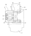
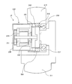
- FIG. 2 is a partial cross-sectional view showing the joint J2 of the robot arm 201.
- the structure of the joint J2 will be described as a structure representative of the structure of each of the joints J1 to J6.
- the other joints J1 and J3 to J6 have the same configuration, and thus description thereof will be omitted.
- the joint drive device 230 includes a rotation motor (hereinafter simply referred to as a motor) 231 and a speed reducer 233 that decelerates the rotation of the rotation shaft 232 of the motor 231.
- a rotation motor hereinafter simply referred to as a motor
- a speed reducer 233 that decelerates the rotation of the rotation shaft 232 of the motor 231.
- the joint J2 includes an encoder 235 that detects the rotation angle of the rotation shaft 232 of the motor 231 (input shaft of the speed reducer 233) (motor angle detection unit).
- the joint J2 includes an encoder 236 that detects an angle of the link 212 with respect to the link 211 (a rotation angle of the output shaft of the speed reducer 233) (joint angle detection unit).
- the encoder 236 detects the angle of the joint J2 (joint angle).
- the motor 231 is an electric motor that can be servo-controlled, for example, and can be composed of, for example, a brushless DC servo motor or an AC servo motor.
- the encoder 235 is preferably an absolute rotary encoder, for example. Although details are not shown in detail, the encoder 235 includes an (absolute value) angle encoder for one rotation, a counter for the total number of rotations of the (absolute value) angle encoder, a backup battery as a power supply unit that supplies power to the counter, and the like It can consist of
- the power feeding unit may be a member that can store electric power supplied from the outside. Even if the supply of the main power supply (801: FIGS. 3 and 4) to the robot arm 201 is turned off, if this backup battery is valid, regardless of whether the main power supply to the robot arm 201 is on or off, The total number of rotations is held in a counter (not shown) of the encoder 235.
- the encoder 235 is attached to the rotating shaft 232 of the motor 231, but may be attached to the input shaft of the speed reducer 233.
- the encoder 236 is a rotary encoder that detects a relative angle between two adjacent links.
- the encoder 236 is a rotary encoder that detects a relative angle between the link 211 and the link 212.
- the encoder 236 may have a configuration in which an encoder scale is provided on the link 211 and a detection head is provided on the link 212 (details not shown).
- the link on which the encoder scale and the detection head are attached is the opposite. There may be.
- the link 211 and the link 212 are rotatably coupled via a cross roller bearing 237.
- the motor 231 is covered and protected by a motor cover 238.
- a brake unit (not shown) is provided between the motor 231 and the encoder 235. The main function of the brake unit is to maintain the posture of the robot arm 201 when the power is turned off.
- the speed reducer 233 is composed of, for example, a wave gear speed reducer that is small and light and has a large reduction ratio.
- the speed reducer 233 includes a web generator 241 that is an input shaft coupled to a rotating shaft 232 of the motor 231, and a circular spline 242 that is an output shaft and is fixed to the link 212.
- the circular spline 242 is directly connected to the link 212, but may be formed integrally with the link 212.
- the speed reducer 233 includes a flex spline 243 that is disposed between the web generator 241 and the circular spline 242 and is fixed to the link 211.
- the flex spline 243 is decelerated at a reduction ratio N with respect to the rotation of the web generator 241 and rotates relative to the circular spline 242. Accordingly, the rotation of the rotating shaft 232 of the motor 231 is decelerated to 1 / N rotation speed by the speed reducer 233, and the link 212 to which the circular spline 242 is fixed is relative to the link 211 to which the flexspline 243 is fixed.
- the joint J2 is bent.
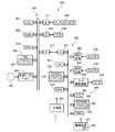
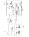
- FIG. 3 is a block diagram showing the configuration of the control system of the robot system 100, particularly the robot controller 300 and the joint controller 340 on the robot arm 201 side.
- the joint control unit 340 shown on the right side of the interface 361 is housed in, for example, the housing of the robot control device 300 and the housing of the robot arm 201.
- the robot control device 300 includes a main control unit 330, a plurality of joint control units 340 (number corresponding to the number of joints: six in the first embodiment), and an output axis signal recording unit 380.
- the main control unit 330 is configured by a computer, and includes a CPU 301 as a calculation unit.
- the main control unit 330 includes a ROM 302, a RAM 303, and an HDD 304 as storage units.
- the main control unit 330 includes a recording disk drive 305 and various interfaces 311 to 313.
- the ROM 301, RAM 303, HDD 304, recording disk drive 305, and various interfaces 311 to 313 are connected to the CPU 301 via a bus.
- the ROM 302 stores basic programs such as BIOS.
- a RAM 303 is a storage device that temporarily stores various types of data such as arithmetic processing results of the CPU 301.
- the HDD 304 is a storage device that stores arithmetic processing results of the CPU 301, various data acquired from the outside, and the like, and records a program 320 for causing the CPU 301 to execute arithmetic processing described later.
- the CPU 301 executes each process of the robot control method based on the program 320 recorded (stored) in the HDD 304.
- the recording disk drive 305 can read various data and programs recorded on the recording disk 321. Recording formats of the recording disk drive 305 and the recording disk 321 are arbitrary, and the recording disk 321 may be, for example, an optical disk (CD (DVD) -R (OM)). The name “recording disk” is merely for convenience, and the recording disk 321 may be a semiconductor memory (disk) such as various flash memories widely used as a storage device.
- the main control unit 330 may be connected to an external storage device (not shown) such as a rewritable nonvolatile memory or an external HDD.
- Teaching pendant 400 that is a teaching unit is connected to interface 311.
- the teaching pendant 400 designates teaching points for teaching the robot arm unit 200, that is, target joint angles of the joints J1 to J6 (target rotational positions of the motors 231 of the joints J1 to J6) by a user input operation. is there.
- the teaching point data is output to the HDD 304 through the interface 311 and the bus.
- the HDD 304 can store teaching point data designated by the teaching pendant 400.
- the CPU 301 can read teaching point data set (stored) in the HDD 304.
- a monitor 500 (display device) as a display unit is connected to the interface 312 and can display, for example, the setting state and control state of the robot system 100 in the form of characters, images, and the like based on the control of the CPU 301.
- the monitor 500 can display information relating to the state of each joint of the robot arm 201 logged as described below, or information relating to the load on each joint acquired based on the information.
- the joint control unit 340 is connected to the interface 313.
- the robot arm 201 has six joints J1 to J6, and the robot control apparatus 300 has six joint control units 340 corresponding to this, but in FIG. 3, one joint control unit 340 is provided. Only the remaining five are not shown.
- Each joint control unit 340 is disposed, for example, in the housing of the robot control apparatus 300. Note that the arrangement position of the joint control unit 340 is not limited to the inside of the housing, and may be arranged on the robot arm 201, for example.
- the CPU 301 calculates the trajectory of the robot arm 201 based on preset teaching points, and outputs a position command signal indicating the target rotation position (control amount of the rotation angle) of the rotation shaft 232 of the motor 231 at predetermined time intervals.
- the data is output to the joint control unit 340.
- the joint control unit 340 includes a CPU 351, an EEPROM 352 and a RAM 353 as a storage unit, an interface 361, detection circuits 362 and 363, and a motor drive circuit 365, which are connected via a bus.
- the CPU 351 executes arithmetic processing according to the program 370.
- the EEPROM 352 is a storage device that stores the program 370.
- the RAM 353 is a storage device that temporarily stores various data such as the calculation processing result of the CPU 351.
- the main control unit 330 has a plurality of (six) interfaces 313 (only one is shown in FIG. 3).
- the interface 313 and the interface 361 of the joint control unit 340 of each joint (J1 to J6) are connected by a cable or the like, and signals can be transmitted and received between the main control unit 330 and each joint control unit 340.
- the encoder 235 is connected to the detection circuit 362, and the encoder 236 is connected to the detection circuit 363.
- the encoders 235 and 236 output pulse signals indicating the detected angle detection values.
- the detection circuits 362 and 363 acquire these pulse signals from the encoders 235 and 236, convert them into signals that can be acquired by the CPU 351, and output them to the CPU 351.
- the motor drive circuit 365 is a motor driver having, for example, a semiconductor switching element, and outputs a voltage of a three-phase alternating current PWM waveform, which is pulse width modulated, to the motor 231 in accordance with an input current command. Supply current.
- the CPU 351 of the joint control unit 340 calculates the amount of current output (current command) to the motor 231 so that the rotation position (rotation angle) of the motor 231 approaches the position command received from the CPU 301 of the main control unit 330.
- the current command is output to the motor drive circuit 365.
- the motor drive circuit 365 supplies the motor 231 with a current corresponding to the received current command.
- the motor 231 receives power supply from the motor drive circuit 365 to generate drive torque, and transmits the torque to the web generator 241 that is the input shaft of the speed reducer 233.
- the circular spline 242 serving as the output shaft rotates at a rotation speed of 1 / N with respect to the rotation of the web generator 241.
- the link 212 rotates relative to the link 211.
- each joint (J1 to J6) supplies current to the motor 231 so that the rotational position of the motor 231 approaches the position command received from the main control unit 330.
- the joint angles of J1 to J6 are controlled.
- the CPU 351, the EEPROM 352, and the RAM 353 of the joint control unit 340 may be arranged for each joint. However, only one set may be arranged as the control on the robot arm 201 side that integrally controls the entire joint control unit 340 of each joint (J1 to J6).
- the robot control apparatus 300 causes the main control unit 330 and the joint control unit 340 to execute the programs 320 and 370, which are operation programs, to operate the robot arm 201.
- Each control unit on the robot arm 201 side is basically operated by the main power source 801.
- the power supply unit of the robot arm 201 is shown by a conceptual block of the main power supply 801, but there are several different forms of specific configurations.
- the main power supply 801 may be configured to be DC-powered from the robot control apparatus 300 side by a power supply line included in the interface 361.
- the main power source 801 may be configured by a power source unit that transforms and stabilizes the commercial power source.
- the supply of the main power source 801 to each control unit on the robot arm 201 side can be turned on or off under the control of the robot control device 300.
- the main power supply 801 is supplied from the robot control device 300 side, the supply of the main power supply 801 is cut off when the robot arm 201 and the robot control device 300 are disconnected during transportation or the like. .
- the main power source 801 may be considered as a “drive power source” that drives the (respective) joints of the robot arm 201.
- the state (joint angle in this embodiment) of each joint (J1 to J6) can be logged (recorded) in a state where the supply of the main power supply 801 (joint drive power supply) is cut off.
- the robot arm 201 is provided with an output axis signal recording unit 380.
- the output shaft signal recording unit 380 includes a CPU 381, an EEPROM 382 as a storage unit, and a RAM 384.
- the CPU 381 of the output shaft signal recording unit 380 acquires the output shaft information detected from the encoders 235 to 236 in accordance with the acquisition program 383.
- the EEPROM 382 constitutes a storage device that records the acquisition program 383.
- the RAM 384 is a storage device that temporarily stores output axis data acquired by the CPU 381.
- the output shaft signal recording unit 380 as a log recording device is configured to be able to operate even when the main power supply (801) supplied to the joint drive source (motor 231) is shut off by the power supply device 901.
- the power supply device 901 supplies the power of the battery 902 as a power supply unit to the CPU 381, the EEPROM 382, and the RAM 384 to operate the output shaft signal recording unit 380 as a log recording device. .
- the output shaft signal recording unit 380 constitutes a log recording device that records (logs) the output value of the joint sensor (encoders 235 to 236 in the present embodiment) and timekeeping information in association with each other (for example, the RAM 384).
- a device such as an RTC (real time clock) is arranged in the output shaft signal recording unit 380. Then, the output information acquired from the joint sensor and the RTC timing information at the time of acquisition are associated with each other in a specific storage format and recorded in a storage device (for example, the RAM 384).
- a method of acquiring output information from the joint sensor in synchronization with the clock of the CPU 381 and sequentially recording it in a storage device (for example, the RAM 384) may be used.
- the time of the output event of the joint sensor can be specified in a load measurement (evaluation) process to be described later by recording the start time of the logging process at the head of the log information.
- the log start time may be recorded on the robot control apparatus 300 side and used for a load measurement (evaluation) process described later.
- an encoder 236 on the output shaft side of the speed reducer 233 (or joint) is considered as a joint sensor for recording output.
- the output of the joint sensor is considered as an “output shaft signal”, and the name of the output shaft signal recording unit 380 is used as the log recording device.
- a storage device that records (logs) the output value of the joint sensor in association with the timing information not only the RAM 384 (backed up by the battery 902) but also an EEPROM 382 or the like may be used.
- the computer-readable recording media are the HDD 304 and the EEPROM 352 and the programs 320 and 370 are stored in the HDD 304 and the EEPROM 352 is described, but the configuration is not limited to this.
- the programs 320 and 370 may be recorded on any recording medium as long as they are computer-readable recording media.
- the recording disk 321 shown in FIG. 3 an external storage device (not shown), or the like may be used.
- a flexible disk, a hard disk, an optical disk, a magneto-optical disk, a CD-ROM, a CD-R, a magnetic tape, a nonvolatile memory, a ROM, or the like can be used as a recording medium.
- the recording medium is a recording medium for the control program of the present invention. Will be configured.
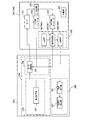
- FIG. 4 is a functional block diagram showing a configuration related to the function of the control system of FIG. 4, the function of the CPU 301 based on the program 320 is shown in a block form, and the function of the CPU 351 and the function of the motor drive circuit 365 based on the program 370 are shown in a block form.
- the joint J1 of the robot arm 201 is shown as a block
- the function of the CPU 381 based on the acquisition program 383 is shown as a block. 4
- different names and different reference numerals are used for members functionally corresponding to the members in FIG. 3, but the reference numerals corresponding to the members in FIG. Is attached in parentheses to indicate the correspondence between the two figures.
- the robot control device 300 has functions of a main control unit 330 that is the first control unit 350, joint control units 340 corresponding to the respective joints J1 to J6, and a load processing unit 390 for the output shaft.
- the load processing unit 390 also has a function of acquiring log information of the recording unit 386 from the robot arm 201 side. In this sense, the load processing unit 390 can be considered as a log acquisition device.
- FIG. 4 only the joint control unit 340 corresponding to the joint J1 and the joint J1 is shown, and the illustration is omitted. However, the robot control device 300 includes the joint control unit 340 corresponding to each of the other joints J2 to J6. Oversees multiple of.
- the main control unit 330 includes a trajectory calculation unit 331, and each joint control unit 340 includes a motor control unit 341.
- the CPU 301 of the main control unit 330 functions as a trajectory calculation unit 331 according to the program 320.
- each joint control unit 340 is a function of the CPU 351 and the motor drive circuit 365 that are operated by the program 370.
- Each joint control unit 340 is a function of the CPU 351 operated by the program 370.
- the trajectory calculation unit 331 calculates the operation (trajectory) of the robot arm 201 based on the teaching point data.
- the teaching point is set by the teaching pendant 400 operated by the operator as a point on the joint space or task space.
- the parameter representing the degree of freedom of the robot arm 201 is defined as a joint angle, and the joint angles of the joints J1 to J6 of the robot arm 201 are defined as ⁇ 1 to ⁇ 6, respectively.
- the configuration of the robot arm 201 is represented by ( ⁇ 1, ⁇ 2, ⁇ 3, ⁇ 4, ⁇ 5, ⁇ 6), and can be regarded as one point on the joint space.
- the parameters representing the degree of freedom of the robot arm 201 for example, the joint angle and the expansion / contraction length
- the configuration of the robot arm 201 can be expressed as a point on the joint space.
- the joint space is a space having the joint angle of the robot arm 201 as a coordinate axis.
- the trajectory calculation unit 331 generates a path of the robot arm 201 that connects a plurality of set teaching points by a predetermined interpolation method (for example, linear interpolation, circular interpolation, joint interpolation, etc.). Then, the trajectory calculation unit 331 generates a trajectory of the robot arm 201 from the generated path of the robot arm 201.
- a predetermined interpolation method for example, linear interpolation, circular interpolation, joint interpolation, etc.
- the path of the robot arm 201 is an ordered set of points in the joint space or task space.
- the trajectory of the robot arm 201 represents a path using time as a parameter, and in this embodiment, is a set of position commands of the motors 231 of the joints J1 to J6 for each time.
- the trajectory data is calculated in advance and stored (set) in the storage unit, for example, the HDD 304, before the robot arm 201 is operated.
- the calculation of the trajectory data will be described with respect to the case where the CPU 301 of the main control unit 330 performs the calculation.
- the trajectory data is preliminarily stored (set) in a storage unit of the main control unit 330, for example, the HDD 304.
- a configuration may be adopted.
- the motor control unit 341 inputs the position command from the trajectory calculation unit 331.
- the position command from the trajectory calculation unit 331 is a position command calculated based on the teaching point as described above.
- the motor control unit 341 performs position control (feedback control) of the motor 231 with reference to the input position command and the value of the encoder 235 so that the rotational position of the motor 231 approaches the position command.
- the output shaft signal recording unit 380 includes a signal processing unit 385 that processes the signal of the output side encoder 236 and a battery unit 387 that is a power supply unit for operating the recording unit 386 that records the processed data.
- the output-side encoder 236, the recording unit 386, and the battery unit 387 can be integrally configured on the same circuit board, for example.
- the output shaft signal recording unit 380 performs only the output signal processing and recording processing of the encoders 235 to 236, and does not have a motor control function for controlling the motor 231. It is power consumption. Therefore, the battery unit 387 that feeds power to the output shaft signal recording unit 380 and drives it can be a small battery or a capacitor, so that it can be easily mounted in the space of the robot arm 201. The battery unit 387 may also serve as a backup battery for the encoder.
- an external power supply unit corresponding to the battery unit 387 and the output shaft signal recording unit 380, a battery, and a recording circuit are externally attached using a connector of the robot arm 201 for connecting to the robot control device 300.
- a possible configuration may be adopted. With such a configuration, there is a possibility that, for example, a large-capacity external battery or a recording circuit can be used for recording the output shaft signal of the joint, and a long-term logging (recording) operation can be performed.
- the output axis signal recording unit 380 and the battery unit 283 that is a power feeding unit are mounted in the robot arm 201. Therefore, even when the main control unit 330 is not connected, the output shaft signal recording unit 380 can acquire the output shaft signal and record it in the recording unit 386 (logging). That is, the information of the output shaft can be recorded (logged) even when the robot arm (part) for transportation or installation is not in operation.
- the robot controller 300 is provided with an output shaft load processing unit 390.
- the load processing unit 390 extracts the output shaft information stored in the recording unit 386, calculates a load applied to the joint, for example, the speed reducer 233, and an overload from the load calculation result.
- An overload determination unit 392 for determining is provided.
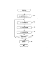
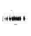
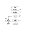
- FIG. 5 is a flowchart illustrating a control procedure for acquiring output axis information according to the present embodiment
- FIG. 6 is a graph of output axis information.
- the output axis information acquisition (log) mode of the CPU 381 is validated in step S1 of FIG.
- This output axis information recording mode is intended to be enabled in a period during which there is a possibility that an overload is applied to the speed reducer 233 of the robot arm 201 such as during transportation or installation work.
- the output axis information recording mode is a mode that can operate even when the robot control device 300 is not connected due to the hardware configuration of the robot arm 201 described above.
- this output shaft information recording mode turns on the main power supply (801) regardless of whether it is connected to the robot controller 300 via a cable or the like, not only during transportation and installation work, but also at the end of the night. It can be used even in a state where it is not done. That is, in this mode, in the state where the supply of the main power source (801) to the joint drive source (motor 231) of the robot arm 201 is cut off, the power of the battery unit 283 is output to the output shaft signal recording unit 380 (log). Logging is performed by supplying power to the recording device.
- the connection between the robot control device 300 and the robot arm 201 is electrically connected via the level of a specific signal line connecting the robot control device 300 and the robot arm 201.
- the method of using the mode as a trigger in the same mode is included.
- a verification personal computer or the like may be connected to the connection connector of the robot control apparatus 300 so that the acquisition mode shift and various settings can be performed.
- the robot arm 201 is provided with an operation switch and a display (for example, 905 in FIG. 1) so that the robot arm 201 can be shifted only. Also good.
- the output axis information recording mode can be started only by operation on the robot arm 201 side.
- the operation switch for starting the output axis information recording mode can be disposed on the back surface or the bottom surface of the base unit 210, for example.
- the operation switch is constituted by a push button switch operated using a DIP switch or a pin arranged in the cover or in the recess.
- the CPU 381 detects angle information of the output shaft from the output side encoder 236 of the robot arm 201 via the detection circuit 363 (step S2).
- the CPU 381 performs signal processing for converting the pulse signal of the output axis information into recordable information by the signal processing unit 385 (step S3). Further, the CPU 381 records the converted output axis information in the recording unit 386 (step S4). At this time, the recording unit 386 stores the output information of the output side encoder 236 (joint sensor) and the timing information in association with each other as described above.
- the angle information from the output side encoder 236 is a pulse signal, and the signal processing unit 385, for example, from the total number of pulses per rotation, information on the joint angle (change over time) as shown in FIG. 6 (1801) Perform processing to convert to.
- the time (time) on the horizontal axis is in seconds, and the angle on the vertical axis is in degrees (deg).
- the joint angle data for each time converted in this way is output for all the axes of the robot arm 201 (six axes in this embodiment), and the data for all the axes is output to the recording unit of the output axis signal recording unit 380. Recording (logging) to 386.
- the motor 231 of this embodiment has a brake (not shown), and when the motor 231 is not energized, the brake works and the motor angle does not change. Therefore, recording by the encoder 235 is not essential. However, when the motor 231 is not equipped with a brake, the motor 231 may be rotated by a load. In that case, the motor 231 is recorded in the encoder 235, the outputs of both encoders or the difference between them is recorded, and the load is evaluated. It is good also as a structure.
- the CPU 381 of the output shaft signal recording unit 380 determines whether it is within a preset recording time (step S5).
- This “recording time” corresponds to a time length during which the robot arm 201 allows the output axis information recording mode, and is, for example, a length of several to several tens of hours. Since the “recording time” is limited by the recording capacity of the recording unit 386 and the capacity of the battery unit 283, in this embodiment, the output axis information recording mode is set in accordance with the time to be measured in advance, for example, the estimated transportation time. "Recording time” can be limited and set.
- the value of “recording time” can be set from the robot controller 300 side by an appropriate setup mode or the like. Further, the joint information recording period or the like may be set manually or automatically in accordance with the “recording time”.
- the CPU 381 repeats the processes of steps S2 to S5 until a predetermined “recording time” arrives.
- an appropriate timer circuit or the RTC device described above can be used (not shown).
- step S5 When the “recording time” determined in step S5 has been reached (step S5, No), the recording is terminated (step S6). As a result, the output axis information acquisition mode ends.
- the robot arm 201 when the robot arm 201 is connected to the robot arm 201 after the robot arm 201 executes the output axis information acquisition mode, the recorded output information of the joint sensors (encoders 236 to 235) is transmitted to the robot controller. Extract to 300 side.
- the robot controller 300 can perform load evaluation on each joint (J1 to J6) based on the output information of the read joint sensors (encoders 236 to 235).
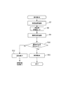
- FIG. 7 shows the flow of extraction (output) of the joint sensor (encoders 236 to 235) recorded (logged) by the output shaft signal recording unit 380 and acquisition (evaluation) of load information based on the information in this embodiment.
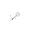
- FIG. 8 is a schematic diagram of a joint configuration
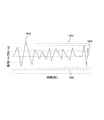
- FIG. 9 is a graph showing load fluctuation.
- step S7 in FIG. 7 the robot system 100 enters an operating state.
- the load acquisition mode is set, and the CPU 381 sends the output axis information stored in the recording unit 386 of the robot arm 201 to the load processing unit 390 of the robot control apparatus 300 (step S8).
- the load of each joint is calculated by the load calculation unit 391 of the load processing unit 390 of the robot control apparatus 300 by the method as shown in FIG. 8 (step S9).
- J is the joint center
- M is the inertia ahead of the joint
- L is the position of the center of gravity
- ⁇ is the joint angle.
- the inertia and the center of gravity position are calculated simultaneously with the load calculation because they change depending on the design information and the posture of the robot arm 201.
- the load applied to the joint is a rotational torque about the joint axis.
- ⁇ is second-order differentiated to obtain angular acceleration ⁇
- inertia moment I is obtained from inertia M and center of gravity L
- load torque T is calculated from I ⁇ ⁇ .
- the waveform of the load torque data 1900 is within the permissible range (1901 to 1902) for almost the period, but exceeds the upper limit (1901) of the load at the peak portion of 1903.
- step S10 Yes
- the result display is performed.
- step S11 the process ends (step S11).
- the allowable value is limited by the speed reducer 233 of each joint, and in the case of the present embodiment, the allowable peak torque of the wave gear speed reducer. If the tolerance is exceeded (No in step S10), it is determined that there is damage to the joint, so a warning is displayed (step S12), and the user is prompted for failure analysis or replacement.
- the load warning display in step S ⁇ b> 12 is performed at the peak portion 1903.
- the time at which the overload occurs can be specified. Therefore, for example, by referring to a separate work time chart (such as an operation table when in transit), the timing at which the overload has occurred. Can be identified and the event that has occurred can be analyzed.
- a separate work time chart such as an operation table when in transit
- the load acquisition and evaluation or further warning processing in steps S8 to S12 may be considered as robot arm diagnosis processing for generating robot arm diagnosis information according to the output data state of the joint sensor.
- This robot arm diagnosis is not limited to an overload warning, but also a robot arm diagnosis that specifically prompts the operator to check, inspect, overhaul, or replace parts depending on the magnitude of the load torque value. It is possible to generate and output information.
- the load is measured by the encoder 236 mounted on the robot arm 201, a special device such as an acceleration sensor is not required. Further, since the encoder 236 is mounted on each joint, there is an advantage that the load of each joint can be accurately obtained and accurate (over) load determination (evaluation) can be performed. According to the configuration of the present embodiment, the output of the joint sensor of each joint of the arm can be directly logged as compared with the method using the packaging as in Patent Document 1, so that the measurement accuracy can be greatly improved. .
- the robot arm 300 has an output axis signal recording unit 380 separately from the robot controller 300, and the output of the joint sensor of each joint can be logged by the arm alone. Therefore, the information of the output shaft can be recorded even when the robot control device 300 is not connected, for example, when it is not operating, transported, or installed, and the presence or absence of an overload that causes a failure can be reliably verified.
- FIGS. 10 to 13 the hardware configuration of parts not shown in FIGS. 10 to 13, for example, the robot arm unit 200, is the same as that of the robot system 100 of the first embodiment. Shall be omitted. Also, the same or corresponding members in FIG. 10 to FIG. 13 are assigned the same reference numerals as those in the first embodiment, and the detailed description thereof will be omitted.
- FIG. 10 corresponds to FIG. 2 of the first embodiment, and is a partial cross-sectional view showing the joint J2 of the robot arm 201 of the present embodiment.
- FIG. 11 corresponds to FIG. 4 of the first embodiment and corresponds to FIG.
- FIG. 2 is a functional block diagram showing the main configuration of the robot system, particularly the functions of its control system.
- an encoder 236 joint angle detection unit that detects an output shaft angle is used as a joint sensor that detects a joint state.
- a torque sensor 501 force sensor
- the torque sensor 501 can be composed of an elastic body that is displaced when torque is applied, and a displacement meter or strain gauge that measures the displacement.
- the torque sensor 501 is disposed between the output side of the speed reducer 233 and the link 212, and detects torque applied to the output shaft of the joint.
- the same configuration as in FIG. 10 can be implemented.
- each joint of the robot arm 201 can be torque-controlled. Thereby, it is possible to perform robot control such that the operation load on the workpieces (W2, W1) is controlled so as not to exceed the allowable value.
- the signal processing unit 385 reads the output of the torque sensor 501 instead of the encoder (236: FIG. 4). Also in the present embodiment, the output information of the joint sensor, that is, the torque value output from the torque sensor 501 is recorded (logged) in the recording unit 386 (RAM 384 or EEPROM 382) in association with the timing information.
- FIG. 12 is a flowchart showing a load display (evaluation) procedure corresponding to FIG. 7 of the first embodiment
- FIG. 13 is a graph of output axis information (load fluctuation) corresponding to FIG. 9 of the first embodiment.
- the torque sensor 501 is mounted as the joint sensor. Therefore, in the procedure of FIG. 12, the joint angle information of the encoder is converted into the joint load ( Step S8) in FIG. 7 is not necessary. Since the other processing steps can be executed as described with reference to FIG. 7, a duplicate description is omitted here.
- the fluctuation of the torque value on the output side of the joint is directly recorded (logged) in the recording unit 386 (RAM 384 or EEPROM 382) on the robot arm 201 side in association with the timing information. Therefore, on the robot control apparatus 300 side, the load torque time variation data as shown in FIG.
- step S12 in FIG. 12 is also performed in this embodiment.
- the log recording operation (output axis information acquisition mode) is executed by the robot arm 201, and after connecting the arm to the robot control device 300, the robot control device 300 is based on the log information acquired from the arm side. The joint load was acquired and evaluated.
- the robot arm 201 alone may be configured to analyze, for example, logged information to detect an overload state and perform warning processing.
- the display 905 of FIG. 1 is arranged on the robot arm 201 as a display means for warning processing.
- the indicator 905 is disposed on the side surface of the base portion 210.
- an encoder may be used as in the first embodiment, or a torque sensor 501 may be used as in the second embodiment.
- the joint load acquisition and evaluation processing in steps S7 to S11 of FIGS. 7 and 12 is performed by the CPU 381 of the output axis signal recording unit 380.
- Control program This control program is stored in a part of the EEPROM 382 (FIG. 3) program (383), for example.
- the output shaft signal recording mode (logging) can be executed in the same manner as described above as shown in FIG. 5 (first embodiment).
- the CPU 381 of the output shaft signal recording unit 380 acquires and evaluates the joint load (steps S7 to S11 in FIGS. 7 and 12), for example, a predetermined “recording time” has elapsed, and the output shaft signal recording mode has ended. Run automatically later.
- the joint load acquisition and evaluation process (steps S7 to S11 in FIG. 7 and FIG. 12) is executed in parallel with the output shaft signal recording mode (FIG. 5), and a warning process is performed almost in real time when an overload occurs. (Step S12 in FIG. 12) may be performed.
- an overload warning it is conceivable to use a display 905 (FIG. 1) arranged on the robot arm 201 to display a warning color (for example, red) or blinking.
- a speaker or the like is disposed on the robot arm 201, an overload warning can be performed by outputting a warning beep sound or a warning (synthetic) sound.
- the robot arm 201 alone is configured to analyze, for example, logged information to detect an overload state and perform warning processing.
- the overload state of the joint can be detected and warning processing can be performed without the robot controller 300.
- the configurations shown in the first and second embodiments can be used for recording (logging) joint information even when the robot arm 201 is physically connected to the robot control device 300.
- the joint information Can be recorded (logged).
- the output shaft signal recording unit 380 starts the output shaft signal recording mode (logging) when the main power is turned off based on the voltage detection of the main power source (801: FIGS. 3, 4, and 11). Control may be performed.
- the load acquisition (or evaluation) by the robot control device 300 can be executed as part of an initialization process performed when the main power is turned on again, for example. With such a configuration, even if an unexpected overload may be applied to the joints of the arm during a period when the robot control device 300 cannot be involved, such as during night hours, it is possible to reliably detect the event and warn Processing can be performed.
- the output shaft signal recording unit 380 may be configured to log the output information of both the encoders 235 to 236 and the torque sensor 501 shown in the first and second embodiments, respectively. In that case, there is a possibility that more various load analysis (acquisition), load evaluation, and diagnosis processing can be performed by combining the output information of the encoder and the torque sensor.
- the present invention supplies a program that realizes one or more functions of the above-described embodiments to a system or apparatus via a network or a storage medium, and one or more processors in a computer of the system or apparatus read and execute the program. It can also be realized by processing. It can also be realized by a circuit (for example, ASIC) that realizes one or more functions.
- a program that realizes one or more functions of the above-described embodiments to a system or apparatus via a network or a storage medium, and one or more processors in a computer of the system or apparatus read and execute the program. It can also be realized by processing. It can also be realized by a circuit (for example, ASIC) that realizes one or more functions.
- ASIC application specific integrated circuit
Landscapes
- Engineering & Computer Science (AREA)
- Robotics (AREA)
- Mechanical Engineering (AREA)
- Human Computer Interaction (AREA)
- Manipulator (AREA)
Abstract
Lorsqu'une source (801) d'alimentation principale est bloquée et lorsqu'il n'est pas possible de faire intervenir un dispositif (300) de commande de robot, la présente invention rend possible l'enregistrement, en utilisant un bras (201) de robot isolément, d'informations se rapportant à l'état de chacune de ses articulations (J1–J6). Le bras (201) de robot comporte: des segments multiples (211–216); des articulations (J1–J6) servant à relier les segments multiples (211–216); et des capteurs (235, 236) servant à détecter l'état des articulations (J1–J6). Le bras (201) de robot comporte également un dispositif (380) d'enregistrement de journal servant à enregistrer des informations délivrées à partir des capteurs (235, 236), et une unité (902) d'alimentation électrique servant à fournir de l'énergie électrique aux capteurs (235, 236) et au dispositif (380) d'enregistrement de journal lorsque la source de puissance d'entraînement des articulations (J1–J6) est bloquée.
Priority Applications (2)
| Application Number | Priority Date | Filing Date | Title |
|---|---|---|---|
| CN201780060093.9A CN109789569A (zh) | 2016-09-28 | 2017-08-28 | 机器人臂、机器人控制装置和机器人系统 |
| US16/283,538 US20190184566A1 (en) | 2016-09-28 | 2019-02-22 | Robot arm, robot control apparatus, and robot system |
Applications Claiming Priority (2)
| Application Number | Priority Date | Filing Date | Title |
|---|---|---|---|
| JP2016-190275 | 2016-09-28 | ||
| JP2016190275A JP6772013B2 (ja) | 2016-09-28 | 2016-09-28 | ロボットアーム、ロボット制御装置、およびロボットシステム |
Related Child Applications (1)
| Application Number | Title | Priority Date | Filing Date |
|---|---|---|---|
| US16/283,538 Continuation US20190184566A1 (en) | 2016-09-28 | 2019-02-22 | Robot arm, robot control apparatus, and robot system |
Publications (1)
| Publication Number | Publication Date |
|---|---|
| WO2018061566A1 true WO2018061566A1 (fr) | 2018-04-05 |
Family
ID=61759458
Family Applications (1)
| Application Number | Title | Priority Date | Filing Date |
|---|---|---|---|
| PCT/JP2017/030683 WO2018061566A1 (fr) | 2016-09-28 | 2017-08-28 | Bras de robot, dispositif de commande de robot, et système de robot |
Country Status (4)
| Country | Link |
|---|---|
| US (1) | US20190184566A1 (fr) |
| JP (1) | JP6772013B2 (fr) |
| CN (1) | CN109789569A (fr) |
| WO (1) | WO2018061566A1 (fr) |
Cited By (1)
| Publication number | Priority date | Publication date | Assignee | Title |
|---|---|---|---|---|
| CN111070200A (zh) * | 2018-10-22 | 2020-04-28 | 新世代机器人暨人工智慧股份有限公司 | 机器人的防碰撞方法 |
Families Citing this family (4)
| Publication number | Priority date | Publication date | Assignee | Title |
|---|---|---|---|---|
| CN112388674B (zh) * | 2020-10-13 | 2023-02-03 | 中铭谷智能机器人(广东)有限公司 | 一种工业机器人电池时钟方法 |
| EP3988261B1 (fr) * | 2020-10-26 | 2023-02-01 | Siemens Aktiengesellschaft | Articulation pour un robot |
| JP6928410B1 (ja) * | 2021-03-22 | 2021-09-01 | リンクウィズ株式会社 | 計測システム、計測方法、プログラム |
| CN116852340A (zh) * | 2023-09-05 | 2023-10-10 | 昆山智能装备研究院 | 高速移载手臂机构 |
Citations (6)
| Publication number | Priority date | Publication date | Assignee | Title |
|---|---|---|---|---|
| JPS61209313A (ja) * | 1985-03-14 | 1986-09-17 | Toshiba Corp | ロボツト関節角検出装置 |
| JPS61252088A (ja) * | 1985-04-30 | 1986-11-10 | フアナツク株式会社 | 産業用ロボツト |
| JP2000162231A (ja) * | 1998-11-25 | 2000-06-16 | Nec Field Service Ltd | 衝撃力検知装置 |
| JP2005030937A (ja) * | 2003-07-07 | 2005-02-03 | Hitachi Metals Ltd | 携帯電子機器装置 |
| JP2015217468A (ja) * | 2014-05-16 | 2015-12-07 | キヤノン株式会社 | ロボットシステムの制御方法、プログラム、記録媒体、ロボットシステム、及び診断装置 |
| JP2016144861A (ja) * | 2015-01-29 | 2016-08-12 | キヤノン株式会社 | ロボット装置、ロボット制御方法、プログラム及び記録媒体 |
Family Cites Families (4)
| Publication number | Priority date | Publication date | Assignee | Title |
|---|---|---|---|---|
| JP4305323B2 (ja) * | 2004-08-11 | 2009-07-29 | ソニー株式会社 | ロボット装置の動作制御装置及び動作制御方法 |
| EP2572837B1 (fr) * | 2010-08-31 | 2014-06-11 | Kabushiki Kaisha Yaskawa Denki | Robot, système robotisé, dispositif de commande de robot et procédé de détermination d'état |
| CN104247356B (zh) * | 2012-04-19 | 2017-02-22 | 松下知识产权经营株式会社 | 多值信号发送装置、多值信号接收装置、多值信号传输系统以及多值信号传输方法 |
| US9622355B2 (en) * | 2013-07-08 | 2017-04-11 | Delphi Technologies, Inc. | Environmentally sealed electrical housing assembly with integrated connector |
-
2016
- 2016-09-28 JP JP2016190275A patent/JP6772013B2/ja active Active
-
2017
- 2017-08-28 CN CN201780060093.9A patent/CN109789569A/zh active Pending
- 2017-08-28 WO PCT/JP2017/030683 patent/WO2018061566A1/fr active Application Filing
-
2019
- 2019-02-22 US US16/283,538 patent/US20190184566A1/en not_active Abandoned
Patent Citations (6)
| Publication number | Priority date | Publication date | Assignee | Title |
|---|---|---|---|---|
| JPS61209313A (ja) * | 1985-03-14 | 1986-09-17 | Toshiba Corp | ロボツト関節角検出装置 |
| JPS61252088A (ja) * | 1985-04-30 | 1986-11-10 | フアナツク株式会社 | 産業用ロボツト |
| JP2000162231A (ja) * | 1998-11-25 | 2000-06-16 | Nec Field Service Ltd | 衝撃力検知装置 |
| JP2005030937A (ja) * | 2003-07-07 | 2005-02-03 | Hitachi Metals Ltd | 携帯電子機器装置 |
| JP2015217468A (ja) * | 2014-05-16 | 2015-12-07 | キヤノン株式会社 | ロボットシステムの制御方法、プログラム、記録媒体、ロボットシステム、及び診断装置 |
| JP2016144861A (ja) * | 2015-01-29 | 2016-08-12 | キヤノン株式会社 | ロボット装置、ロボット制御方法、プログラム及び記録媒体 |
Cited By (1)
| Publication number | Priority date | Publication date | Assignee | Title |
|---|---|---|---|---|
| CN111070200A (zh) * | 2018-10-22 | 2020-04-28 | 新世代机器人暨人工智慧股份有限公司 | 机器人的防碰撞方法 |
Also Published As
| Publication number | Publication date |
|---|---|
| US20190184566A1 (en) | 2019-06-20 |
| JP2018051683A (ja) | 2018-04-05 |
| JP6772013B2 (ja) | 2020-10-21 |
| CN109789569A (zh) | 2019-05-21 |
Similar Documents
| Publication | Publication Date | Title |
|---|---|---|
| WO2018061566A1 (fr) | Bras de robot, dispositif de commande de robot, et système de robot | |
| JP6164948B2 (ja) | ロボット装置及び部品の製造方法 | |
| US8798790B2 (en) | Apparatus and method for detecting contact position of robot | |
| KR102007536B1 (ko) | 토크를 검출하기 위한 방법 및 산업용 로봇 | |
| JP6771888B2 (ja) | ロボット装置、制御方法、物品の製造方法、プログラム及び記録媒体 | |
| DK1445075T3 (en) | Method of monitoring a robot and robot with monitoring device | |
| JP2016168651A (ja) | ロボット制御方法、ロボット装置、プログラム及び記録媒体 | |
| JP6584102B2 (ja) | ロボット装置、ロボット制御方法、プログラム、記録媒体、及び物品の製造方法 | |
| JP2017019080A (ja) | ロボット装置の測定方法、および回転駆動装置の測定方法 | |
| US11413759B2 (en) | Robot apparatus, control method for controlling the same, non-transitory computer-readable recording medium, manufacturing system, and method for manufacturing an article | |
| JP6512790B2 (ja) | ロボット制御方法、ロボット装置、プログラム、記録媒体及び物品の製造方法 | |
| JP6484287B2 (ja) | リニアガイドの損傷検知装置及び損傷検知方法 | |
| JP2017124455A (ja) | ロボット装置、ロボット制御方法、プログラム及び記録媒体 | |
| JP2017140685A (ja) | ロボット装置、ロボット制御方法、部品の製造方法、プログラム、記録媒体 | |
| JP6839369B2 (ja) | ロボットシステム | |
| CN109955279A (zh) | 机器人手、其控制方法、物品的组装方法及存储介质 | |
| JP7214695B2 (ja) | ロボット、駆動装置、ロボットシステム、駆動装置システム、プログラム | |
| JP2020104177A (ja) | ロボット装置、ロボット装置の制御方法、プログラム、記録媒体、物品の製造方法 | |
| JP6521736B2 (ja) | ロボット装置、ロボット制御方法、プログラム、記録媒体及び組立部品の製造方法 | |
| WO2019171516A1 (fr) | Système d'identification de paramètre inertiel d'un robot articulé verticalement, procédé d'identification de paramètre inertiel, et dispositif et procédé de commande pour robot articulé verticalement | |
| JP7278803B2 (ja) | 情報処理方法、情報処理装置、ロボットシステム、ロボットシステムの制御方法、ロボットシステムを用いた物品の製造方法、プログラム及び記録媒体 | |
| JP7267725B2 (ja) | ロボットの制御方法、プログラム、記録媒体、ロボットシステム、物品の製造方法 | |
| JP6840875B2 (ja) | 制御方法、制御プログラム、記録媒体、ロボットシステム、物品の製造方法、回転駆動装置の制御方法 | |
| JP2019111597A (ja) | ロボットアーム、ロボット装置 | |
| JP5088217B2 (ja) | 産業用ロボットの出力トルク制限回路 |
Legal Events
| Date | Code | Title | Description |
|---|---|---|---|
| 121 | Ep: the epo has been informed by wipo that ep was designated in this application |
Ref document number: 17855524 Country of ref document: EP Kind code of ref document: A1 |
|
| NENP | Non-entry into the national phase |
Ref country code: DE |
|
| 122 | Ep: pct application non-entry in european phase |
Ref document number: 17855524 Country of ref document: EP Kind code of ref document: A1 |