WO2018061293A1 - 無線端末、基地局、及びこれらの方法 - Google Patents
無線端末、基地局、及びこれらの方法 Download PDFInfo
- Publication number
- WO2018061293A1 WO2018061293A1 PCT/JP2017/018330 JP2017018330W WO2018061293A1 WO 2018061293 A1 WO2018061293 A1 WO 2018061293A1 JP 2017018330 W JP2017018330 W JP 2017018330W WO 2018061293 A1 WO2018061293 A1 WO 2018061293A1
- Authority
- WO
- WIPO (PCT)
- Prior art keywords
- carrier
- wireless terminal
- base station
- transmission
- beams
- Prior art date
Links
Images


Classifications
-
- H—ELECTRICITY
- H04—ELECTRIC COMMUNICATION TECHNIQUE
- H04B—TRANSMISSION
- H04B7/00—Radio transmission systems, i.e. using radiation field
- H04B7/02—Diversity systems; Multi-antenna system, i.e. transmission or reception using multiple antennas
- H04B7/04—Diversity systems; Multi-antenna system, i.e. transmission or reception using multiple antennas using two or more spaced independent antennas
- H04B7/0408—Diversity systems; Multi-antenna system, i.e. transmission or reception using multiple antennas using two or more spaced independent antennas using two or more beams, i.e. beam diversity
-
- H—ELECTRICITY
- H04—ELECTRIC COMMUNICATION TECHNIQUE
- H04W—WIRELESS COMMUNICATION NETWORKS
- H04W72/00—Local resource management
- H04W72/50—Allocation or scheduling criteria for wireless resources
- H04W72/51—Allocation or scheduling criteria for wireless resources based on terminal or device properties
-
- H—ELECTRICITY
- H04—ELECTRIC COMMUNICATION TECHNIQUE
- H04B—TRANSMISSION
- H04B7/00—Radio transmission systems, i.e. using radiation field
- H04B7/02—Diversity systems; Multi-antenna system, i.e. transmission or reception using multiple antennas
- H04B7/04—Diversity systems; Multi-antenna system, i.e. transmission or reception using multiple antennas using two or more spaced independent antennas
- H04B7/06—Diversity systems; Multi-antenna system, i.e. transmission or reception using multiple antennas using two or more spaced independent antennas at the transmitting station
- H04B7/0686—Hybrid systems, i.e. switching and simultaneous transmission
- H04B7/0695—Hybrid systems, i.e. switching and simultaneous transmission using beam selection
-
- H—ELECTRICITY
- H04—ELECTRIC COMMUNICATION TECHNIQUE
- H04B—TRANSMISSION
- H04B7/00—Radio transmission systems, i.e. using radiation field
- H04B7/02—Diversity systems; Multi-antenna system, i.e. transmission or reception using multiple antennas
- H04B7/10—Polarisation diversity; Directional diversity
-
- H—ELECTRICITY
- H04—ELECTRIC COMMUNICATION TECHNIQUE
- H04L—TRANSMISSION OF DIGITAL INFORMATION, e.g. TELEGRAPHIC COMMUNICATION
- H04L5/00—Arrangements affording multiple use of the transmission path
- H04L5/003—Arrangements for allocating sub-channels of the transmission path
- H04L5/0032—Distributed allocation, i.e. involving a plurality of allocating devices, each making partial allocation
-
- H—ELECTRICITY
- H04—ELECTRIC COMMUNICATION TECHNIQUE
- H04L—TRANSMISSION OF DIGITAL INFORMATION, e.g. TELEGRAPHIC COMMUNICATION
- H04L5/00—Arrangements affording multiple use of the transmission path
- H04L5/003—Arrangements for allocating sub-channels of the transmission path
- H04L5/0048—Allocation of pilot signals, i.e. of signals known to the receiver
- H04L5/0051—Allocation of pilot signals, i.e. of signals known to the receiver of dedicated pilots, i.e. pilots destined for a single user or terminal
-
- H—ELECTRICITY
- H04—ELECTRIC COMMUNICATION TECHNIQUE
- H04W—WIRELESS COMMUNICATION NETWORKS
- H04W16/00—Network planning, e.g. coverage or traffic planning tools; Network deployment, e.g. resource partitioning or cells structures
- H04W16/24—Cell structures
- H04W16/28—Cell structures using beam steering
-
- H—ELECTRICITY
- H04—ELECTRIC COMMUNICATION TECHNIQUE
- H04W—WIRELESS COMMUNICATION NETWORKS
- H04W72/00—Local resource management
- H04W72/04—Wireless resource allocation
-
- H—ELECTRICITY
- H04—ELECTRIC COMMUNICATION TECHNIQUE
- H04W—WIRELESS COMMUNICATION NETWORKS
- H04W72/00—Local resource management
- H04W72/04—Wireless resource allocation
- H04W72/044—Wireless resource allocation based on the type of the allocated resource
- H04W72/046—Wireless resource allocation based on the type of the allocated resource the resource being in the space domain, e.g. beams
-
- H—ELECTRICITY
- H04—ELECTRIC COMMUNICATION TECHNIQUE
- H04W—WIRELESS COMMUNICATION NETWORKS
- H04W72/00—Local resource management
- H04W72/50—Allocation or scheduling criteria for wireless resources
- H04W72/54—Allocation or scheduling criteria for wireless resources based on quality criteria
- H04W72/542—Allocation or scheduling criteria for wireless resources based on quality criteria using measured or perceived quality
Definitions
- the present disclosure relates to wireless communication, and more particularly to wireless communication using a directional beam.
- 5G is a combination of LTE and LTE-Advanced continuous enhancement / evolution and the introduction of a new 5G air interface (new Radio Access Technology (RAT)).
- the new RAT is, for example, a frequency band higher than the frequency band (eg, 6 GHz or less) targeted for the continuous development of LTE / LTE-Advanced, such as a centimeter wave band of 10 GHz or more and a millimeter band of 30 GHz or more. Support waveband.
- the fifth generation mobile communication system is also called Next Generation (NextGen) System (NG System).
- the new RAT for NG System is called New Radio (NR), 5G RAT, or NG RAT.
- the new radio access network (Radio Access Network (RAN)) and core network for NG System are called NextGen RAN (NG RAN) or New RAN and NextGen Core (NG Core), respectively.
- a wireless terminal (User Equipment (UE)) connected to the NG System is called NextGen UE (NG UE).
- a base station that supports New Radio (NR) is called NG NodeB (NG NB), NR NodeB (NR NB), or gNB.
- NG NB NG NodeB
- NR NB NR NodeB
- gNB gNodeB
- LTE Long Term Evolution
- LTE-Advanced Pro LTE +, or enhanced LTE (eLTE).
- EPC Evolved Packet Core
- MME Mobility Management Entity
- S-GW Serving Gateway
- PDN Packet Data Network
- P-GW Packet Data Network Gateway
- the NG system supports the higher frequency band (e.g., more than 6 GHz).
- a high antenna gain is required to compensate for propagation loss (path loss).
- path loss propagation loss
- a multi-antenna that uses a very large number of antenna elements (eg, several hundred antenna elements) in a high frequency band has a realistic size. It can be realized with an antenna.
- large antenna arrays are used to form high gain beams. Beam means a radiation pattern having at least some level of directivity. High gain beams are narrow compared to the wide sector beams used in lower frequency bands (e.g., present LTE bands (below 6 GHz)). Therefore, multiple beams are needed to cover the desired cell area.
- TRP Transmission and Reception Points
- the TRPs may be arranged in a centralized manner or may be arranged in a distributed manner.
- Each TRP may form a plurality of beams.
- TRP can also be called remoteremradiohead (RRH).
- RRH remoteremradiohead
- the beam-related procedure includes mobility (procedure) and beam management (procedure) (Non-Patent Document 6).
- Beam management to acquire and maintain TRP (s) and / or UE beams that can be used for downlink (DL) and uplink (UL) transmission / reception. This is a set of layer 1 (L1) / layer 2 (L2) procedures.
- Beam management includes at least beam determination, beam measurement, beam reporting, and beam sweeping. Beam determination is a procedure for TRP (s) or UE to select its own transmit / receive beam (its own Tx / Rx beam (s)).
- Beam measurement is a procedure for TRP (s) or UE to measure the characteristics of a received beamformed signal.
- Beam reporting is a procedure for the UE to report information on beamformed signals (signal (s)) based on beam measurements.
- a beam sweep is an operation that covers a spatial area with beams that are transmitted and / or received during a time interval in a predetermined manner.
- NR is also expected to use different radio parameter sets for multiple frequency bands. For example, a subcarrier interval (spacing), a symbol length (symbol length), a transmission time interval (TTI), and a subframe duration (subframe duration) differ depending on the frequency band. These radio parameter sets are called numerology.
- UE and NR NB support aggregation of multiple NR carriers of different numerologies.
- aggregation of multiple NR carriers of different numerologies can be performed by using lower layer aggregation (lower layer aggregation) such as the existing LTE Carrier Aggregation (CA) or upper layer aggregation such as existing Dual layer connectivity (upper layer aggregation).
- lower layer aggregation such as the existing LTE Carrier Aggregation (CA)
- upper layer aggregation such as existing Dual layer connectivity (upper layer aggregation).
- the present inventor examined UE mobility between beams and found some problems.
- One of the objectives to be achieved by the embodiments disclosed herein is to provide an apparatus, a method, and a program that contribute to providing a procedure for UE mobility between beams. It should be noted that this object is only one of the objects that the embodiments disclosed herein intend to achieve. Other objects or problems and novel features will become apparent from the description of the present specification or the accompanying drawings.
- a wireless terminal includes a wireless transceiver and at least one processor.
- the wireless transceiver is configured to transmit a signal to a base station and receive a signal from the base station.
- the at least one processor is configured to receive beam setting information from the base station and measure a first plurality of transmit beams transmitted from the base station according to the beam setting information.
- the at least one processor further receives one or more beams selected from the first plurality of transmission beams based on the measurement results of the first plurality of transmission beams from the base station. It is configured to be used as a first serving beam for transmission to a wireless terminal.
- Each of the first plurality of transmit beams carries a beamformed reference signal measured by the wireless terminal.
- the beam setting information includes a reference signal setting indicating a radio resource used in each beam for transmission of the beamformed reference signal.
- the base station includes a wireless transceiver and at least one processor.
- the wireless transceiver is configured to transmit signals to and receive signals from the wireless terminal.
- the at least one processor is configured to transmit beam setting information to the wireless terminal.
- the at least one processor is further configured to select one or more of the first plurality of transmission beams based on a measurement result of the first plurality of transmission beams transmitted from the base station by the wireless terminal.
- the above beam is configured to be used as a first serving beam for transmission from the base station to the wireless terminal.
- Each of the first plurality of transmit beams carries a beamformed reference signal measured by the wireless terminal.
- the beam setting information includes a reference signal setting indicating a radio resource used in each beam for transmission of the beamformed reference signal.
- a method performed by a wireless terminal includes: (a) receiving beam setting information from the base station; and (b) setting a first plurality of transmission beams transmitted from the base station to the beam setting. Measuring according to the information, and (c) one or more beams selected from the first plurality of transmission beams based on the measurement results of the first plurality of transmission beams from the base station Using as a first serving beam for transmission to the wireless terminal.
- Each of the first plurality of transmit beams carries a beamformed reference signal measured by the wireless terminal.
- the beam setting information includes a reference signal setting indicating a radio resource used in each beam for transmission of the beamformed reference signal.
- a method performed by a base station includes: (a) transmitting beam setting information to a wireless terminal; and (b) the wireless terminal of a first plurality of transmission beams transmitted from the base station. Using one or more beams selected from the first plurality of transmission beams based on a measurement result by the base station as a first serving beam for transmission from the base station to the wireless terminal. including. Each of the first plurality of transmit beams carries a beamformed reference signal measured by the wireless terminal.
- the beam setting information includes a reference signal setting indicating a radio resource used in each beam for transmission of the beamformed reference signal.
- the program includes a group of instructions (software code) for causing the computer to perform the method according to the third or fourth aspect described above when read by the computer.
- FIG. 2 is a diagram illustrating a configuration example of a wireless communication network and an example of beam level mobility according to an embodiment of the present disclosure.
- FIG. 2 is a diagram illustrating a configuration example of a wireless communication network and an example of beam level mobility according to an embodiment of the present disclosure.
- FIG. 2 is a diagram illustrating a configuration example of a wireless communication network and an example of beam level mobility according to an embodiment of the present disclosure.
- FIG. 2 is a diagram illustrating a configuration example of a wireless communication network and an example of beam level mobility according to an embodiment of the present disclosure.
- FIG. FIG. 5 is a sequence diagram illustrating an example of a procedure for UE mobility between beams according to an embodiment of the present disclosure.
- FIG. 5 is a sequence diagram illustrating an example of a procedure for UE mobility between beams according to an embodiment of the present disclosure.
- FIG. 5 is a sequence diagram illustrating an example of a procedure for UE mobility between beams according to an embodiment of the present disclosure.
- FIG. 6 is a diagram illustrating an example of a user plane protocol stack for aggregation of multiple carriers of different numerologies according to an embodiment of the present disclosure.
- FIG. 6 is a diagram illustrating an example of a user plane protocol stack for aggregation of multiple carriers of different numerologies according to an embodiment of the present disclosure.
- FIG. 6 is a diagram illustrating an example of a user plane protocol stack for aggregation of multiple carriers of different numerologies according to an embodiment of the present disclosure.
- FIG. 6 is a diagram illustrating an example of a user plane protocol stack for aggregation of multiple carriers of different numerologies according to an embodiment of the present disclosure.
- 2 is a block diagram illustrating a configuration example of a base station according to an embodiment of the present disclosure.
- FIG. 3 is a block diagram illustrating a configuration example of a wireless terminal according to an embodiment of the present disclosure.
- the plurality of embodiments described below can be implemented independently or in appropriate combinations.
- the plurality of embodiments have different novel features. Therefore, these multiple embodiments contribute to solving different purposes or problems and contribute to producing different effects.
- FIG. 1 to FIG. 4 are diagrams showing some configuration examples of the wireless communication network according to the present embodiment and some examples of beam level mobility.
- the radio communication network includes a New Radio (NR) base station (ie, NR NodeB (NR NB)) 1 and a radio terminal (UE) 2.
- the NR NB1 forms a plurality of transmission beams 10 and transmits a beamformed reference signal (RS) in each transmission beam.
- RS beamformed reference signal
- a beamformed reference signal can also be called a beam-specific reference signal (BRS).
- the beamformed reference signal may be a precoded Channel State Information (CSI) reference signal (precoded CSI-RS).
- the beamformed reference signal may be UE specific (UE-specific) or UE non-specific (non-UE-specific).
- the plurality of transmission beams 10 are specified by a beam identifier (beam ID)).
- beam ID can also be called a beam index.
- the beamformed reference signal may include a beam identifier.
- the beam ID is a radio resource (eg, subcarrier, time slot, resource block, or spreading code, or any combination thereof) used for transmitting the beamformed reference signal, or the radio resource ( ) May be specified by an index linked in advance.
- the beam identifier may be a TRP identifier (TRP ID).
- TRP ID TRP identifier
- a TRP identifier may be used to distinguish between multiple transmit beams 10.
- the plurality of beam IDs of the plurality of transmission beams 10 may be associated with the same cell identifier (e.g., E-UTRAN Cell Global ID (ECGI), Physical Cell Identifier (PCI)) provided by the NRNB1.
- ECGI E-UTRAN Cell Global ID
- PCI Physical Cell Identifier
- multiple transmit beams 10 covering the same cell may be associated with the same cell identifier.
- UE2 receives beam setting information from NR NB1 in any cell managed by NR NB1, and measures a plurality of transmission beams 10 of NR NB1 according to the beam setting information.
- the beam setting information includes a reference signal setting indicating a radio resource used in each transmission beam 10 for transmission of a beamformed reference signal.
- NR NB1 and UE2 use one or more beams selected from the plurality of transmission beams 10 based on the measurement results of the plurality of transmission beams by UE2 as serving beams for transmission from NR NB1 to UE2. use.
- the selection (or determination) of the serving beam based on the measurement results of a plurality of transmission beams by UE2 may be performed by UE2 or may be performed by NR NB1.
- the NR NB1 may transmit beam setting information regarding a plurality of transmission beams 10 of other cells in the high frequency band in a low frequency band cell that does not perform beam forming or uses a wide sector beam.
- the low frequency band cell may be (e) an LTE-macro cell and may be used to maintain a control connection between NR-NB1 and UE2.
- the beam setting information may be transmitted from the NR NB1 to the UE2 in the serving beam that has already been selected (set).
- the beam setting information transmitted by the serving beam may be used for measurement of the serving beam and measurement and (re) selection of other transmission beams.
- the beam setting information may include a beam setting set information element (beam configuration information element (IE)).
- the beam setting information may be included in system information (System Information Block (SIB)) broadcast by NR NB1, or may be sent to UE2 by dedicated Radio Resource Control (RRC) signaling.
- SIB System Information Block
- RRC Radio Resource Control
- UE2 when UE2 has the beamforming function according to the present embodiment and NR NB1 supports (enables) the beamforming function in the serving cell of UE2, UE2 provides beam setting information to NR NB1. May be requested to be transmitted.
- NB1 may alert
- the beam setting information may further include a beam identifier (e.g., “beam” ID, “TRP” ID).
- the beam setting information may include an area setting corresponding to each beam or TRP (or RRH) used for transmission of each beam.
- the area setting may indicate a geographic area (e.g., zone, beam area, predefined cell partial area) associated with the beam identifier.
- the area setting may include information on latitude and longitude as information indicating a geographical area.
- the beam setting information may include a beam selection criterion (or beam determination criterion).
- the beam selection criteria include, for example, the reception quality (eg, received signal strength (eg, Reference Signal Received Power (RSRP)) and the received signal quality (eg, Reference Signal Received Quality (RSRQ) obtained by beam measurement. )), Signal to Noise Ratio (SNR), or Signal to Interference-pulse-Noise Ratio (SINR)).
- the beam setting information may include a beam report standard.
- the beam reporting standard may include, for example, a threshold value or offset applied to the reception quality (e.g., received signal strength, SNR, or SINR) of the beamformed reference signal obtained by beam measurement.
- the beam setting information may include beam / subframe setting information regarding the beam pattern.
- the number of beams that can be transmitted simultaneously by the NR NB1 may be less than the number of beams necessary to cover the desired cell area.
- the NR NB1 may perform beam sweeping to cover a desired cell area. That is, NR NB1 sweeps the cell area in the time domain by sequentially activating multiple beam sets covering different areas in the cell.
- the beam set means one or a plurality of transmission beams 10 simultaneously formed by NR NB1.
- the beam / subframe setting information may include setting information (beam sweeping configuration) of beam sweeping (sweeping) by NR NB1.
- the setting information of the beam sweep may include a time-domain beam sweeping pattern (sweeping pattern).
- the beam sweeping pattern includes, for example, an OFDM symbol, a slot made up of a plurality of OFDM symbols, a subframe, and a transmission beam assigned with a beam ID (for each of N transmission beams 10 in the example of FIG. 1). It may be indicated by a bitmap format in which any one of the frames is used, or a combination thereof. For example, “1” (or “0”) in the bitmap may indicate that a signal is transmitted using the transmission beam.
- the beam subframe configuration information may include beam pattern information in the frequency domain.
- a beam set may be set in units of a plurality of frequency resources (e.g., Subcarrier, Physical Resource Block: PRB. Sweep block). That is, a signal may be transmitted using a different beam for each of a plurality of frequency resources.
- One sweep block uses a single active beam to cover a specific area within the cell.
- the NR NB1 uses a plurality of TRPs 101A and 101B. Each TRP 101 forms one or more transmit beams 10.
- the UE 2 moves between a plurality of transmission beams 10 in one TRP 101.
- the beam setting information may include settings regarding a plurality of transmission beams 10 in one TRP 101.
- the NR NB1 uses a plurality of TRPs 101A and 101B. Each TRP forms one or more transmit beams 10.
- UE2 moves from the transmission beam 10A formed by the TRP 101A to the transmission beam 10B formed by the TRP 101B.
- the beam setting information may include settings regarding one or more transmission beams 10 formed by each TRP 101 managed by the NR NB1.
- NR NB1 provides a plurality of carriers (i.e., carriers # 1, # 2, and # 3) using a plurality of TRP101.
- the coverages of the three carriers # 1, # 2, and # 3 are hierarchically formed in substantially the same geographical area.
- UE2 supports aggregation of multiple carriers.
- the multiple carriers provided by NR NB1 may belong to different frequency bands, and different numerologies (eg, subcarrier spacing, symbol length), Transmission Interval (TTI), and subframe duration (Subframe duration)) may be used.
- numerologies eg, subcarrier spacing, symbol length), Transmission Interval (TTI), and subframe duration (Subframe duration)
- the TRP 101A operates the carrier # 1 (ie, cell # 1) in the 5 GHz band and forms a plurality of transmission beams 10A of the carrier # 1, and the TRP 101B is the carrier # 2 in the 5 GHz band. (Ie, cell # 2) is operated to form a plurality of transmission beams 10B of carrier # 2.
- the TRP 101C operates carrier # 3 (i.e., cell # 3) in the 30 GHz band and forms a plurality of transmission beams 10C of the carrier # 3.
- a high antenna gain is required to compensate for propagation loss (path loss).
- the beam width of the transmission beam 10C in the 30 GHz band is the transmission beam 10A in the 5 GHz band. And narrower than the beam width of 10B.
- NB1 may perform beam selection per carrier, ie, within each carrier. That is, UE2 or NR NB1 selects a serving beam from a plurality of transmission beams in carrier # 1, a serving beam selection from a plurality of transmission beams in carrier # 2, and a plurality of transmission beams in carrier # 3. Serving beam selection may be performed independently. Instead, the UE 2 or the NR NB 1 may perform beam selection in a predetermined carrier set unit, that is, within the carrier set.
- the carrier set may be a plurality of carriers (e.g., carrier # 1 and carrier # 2) belonging to the same frequency band. Alternatively, the carrier set may be a plurality of carriers using the same numerology.
- the carrier set may be a plurality of carriers using a plurality of numerologies that are similarly handled based on a predetermined criterion.
- the beam setting information may include settings regarding one or more transmission beams 10 formed by each TRP 101 managed by NR NB1.
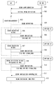
- FIG. 5 is a sequence diagram illustrating an example of a procedure for UE mobility between beams.
- UE2 selects a serving beam.
- NB1 transmits beam setting (beam
- NR NB1 and UE2 perform initial beam selection (initial beam selection).
- NR NB1 may specify a serving beam for UE2. Instead of this, the UE 2 may select the first serving beam in the same manner as the beam (re-) selection described later.
- UE2 measures the transmission beam transmitted from NR NB1 according to the beam setting. Specifically, UE2 tries to receive one or more beamformed reference signals respectively corresponding to one or more transmission beams specified in the beam setting, and the received beamformed reference signals are received. Measure the reception quality. UE2 may measure the received signal strength, SNR, or SINR) of the beamformed reference signal.
- UE2 sends a beam report (beam reporting) to NR NB1.
- the beam report includes beam information based on the measurement result in step 503.
- the beam information may indicate reception quality of all beamformed reference signals measured by UE2.
- the beam information may indicate the reception quality of the beamformed reference signal, the beam ID, or a combination thereof, in which the reception quality by the UE 2 exceeds the threshold value.
- the beam report of step 504 may be abbreviate
- UE2 and NR NB1 select among option A1 (ie, steps 505 and 506), option A2 (ie, steps 507 and 508), and option A3 (ie, steps 509 and 510) shown in FIG. Execute any one.
- the RRC layer does not participate in beam selection
- the Medium Access Control (MAC) sublayer of UE2 performs beam selection.
- UE2 performs serving beam selection in the MAC sublayer.
- UE2 may select the serving beam based on the beam selection criteria included in the beam settings of step 501.
- the beam selection criteria may include a threshold or offset applied to the reception quality of the beamformed reference signal. For example, when the reception quality of the beamformed reference signal of a certain transmission beam is greater than a reception threshold of the beamformed reference signal of the current serving beam by UE2, the UE2 sets the transmission beam as a new serving beam.
- UE2 transmits a MAC layer message (beam indication message) indicating the serving beam newly selected by UE2 to NR NB1.
- the MAC layer message is processed by the MAC sublayer of NR NB1.
- the MAC layer message may be MAC Control Element (CE).
- the MAC sublayer of UE2 performs beam selection and notifies NR NB1 of the beam for which the RRC layer of UE2 is selected.
- UE2 performs serving beam selection in the MAC sublayer.
- the processing in step 507 may be similar to the processing in step 505 described above.
- UE2 informs NR NB1 of the serving beam newly selected by UE2 by RRC signaling.
- the RRC layer of UE2 triggers beam selection to the MAC sublayer of UE2, and notifies the NR NB1 of the beam in which the RRC layer or MAC sublayer of UE2 is selected.
- the MAC sublayer of UE2 performs a serving beam selection process triggered by the RRC layer of UE2.
- UE2 informs NR NB1 of the serving beam newly selected by UE2 by RRC signaling or MAC sublayer message (e.g., MAC CE).
- NR NB1 transmits a response message (beam indication acknowledge message) to UE2 in response to reception of the beam indication message in step 506, 508, or 510.
- the transmission of the response message in step 511 may be omitted.
- step 512 UE2 and NR NB1 switch the serving beam for transmission from NR NB1 to UE2 from the current beam to a new beam selected by UE2.
- the process of step 512 is performed in the MAC sublayer and the physical (PHY) layer.
- the MAC sublayer of UE2 instructs the PHY layer of UE2 to switch the serving beam.
- (Serving) beam switching can be expressed as (serving) beam changing or (serving) beam modification.
- NR NB1 or UE2 or both may perform at least one of the processes listed below: ⁇ Random Access Channel (RACH) procedure; -UE2 Power Headroom Report (PHR) transmission; -Flush soft buffer for Hybrid Automatic Repeat reQuest (HARQ); -HARQ restart from initial transmission for not-yet-successful data; CSI derived reset (stop and restart from start); and MAC sublayer timer reset or restart.
- RACH Random Access Channel
- PHR Power Headroom Report
- HARQ Hybrid Automatic Repeat reQuest
- HARQ restart from initial transmission for not-yet-successful data
- CSI derived reset stop and restart from start
- MAC sublayer timer reset or restart MAC sublayer timer reset or restart.
- the RACH procedure (Random access procedure) is, for example, for determining (or adjusting) at least one of uplink signal transmission timing and uplink transmission power for the switched beam, or for uplink This is done for scheduling request (SR) for data transmission.
- the RACH procedure may be used to recognize on the network side (NR2NB1) that UE2 has completed switching of the serving beam (knowing that UE3 has moved).
- radio resources RACH preamble, time / frequency PRACH resource, beam configuration
- used in the RACH procedure may be transmitted from NR ⁇ ⁇ ⁇ NB1 to UE2 in advance with beam setting information.
- NB1 transmits uplink signal by calculating from the timing adjustment value (Timing
- the timing may be determined (or adjusted).
- the same timing adjustment value (TA) or the same setting may be used before and after beam switching.
- PHR transmission is performed, for example, to determine (or adjust) uplink transmission power for the beam after switching.
- UE2 may trigger PHR when the beam switches. Further or alternatively, UE2 determines whether or not to perform PHR transmission depending on whether or not the value of propagation loss (path loss) has changed from a predetermined threshold value notified from NR NB1 due to beam switching. May be.
- UE 2 uses the HARQ software used before switching.
- the buffer may be flushed.
- UE 2 may discard the held HARQ soft buffer information.
- UE2 may reset the calculation of Channel Quality Indicator (CQI) for the downlink reference signal (e.g., beamformed RS).
- CQI Channel Quality Indicator
- the UE 2 may operate so as to derive an effective CQI value within a predetermined period (eg, n + 8, n + 24) from the time of beam switching (eg, subframe n). .
- Target MAC sublayer timers include, for example, timers related to PHR (eg, periodicPHR-Timer, prohibitPHR-Timer), timers related to Discontinuous Reception (DRX) (eg, drx-InactivityTimer, drx-RetransmissionTimer), uplink synchronization timer (Ie timeAlignmentTimer), at least one of timers related to scheduling requests (eg, sr-ProhibitTimer), and timers related to buffer status reports (eg, periodicBSR-Timer, prohibitBSR-Timer).
- PHR eg, periodicPHR-Timer, prohibitPHR-Timer
- DRX Discontinuous Reception
- Ie timeAlignmentTimer Uplink synchronization timer
- timers related to scheduling requests eg, sr-ProhibitTimer
- timers related to buffer status reports eg, periodicBSR-Timer, prohibitBSR-Timer.
- FIG. 6 is a sequence diagram showing another example of a procedure for UE mobility between beams.
- NR NB1 selects the serving beam.
- NB1 transmits beam setting (beam
- the NR NB1 and the UE2 perform initial beam selection (initial beam selection).
- NR NB1 may designate a serving beam for UE2, as in beam (re-) selection described later.
- UE2 may select the first serving beam.
- step 603 UE2 measures the transmission beam transmitted from NR NB1 according to the beam setting.
- step 604 UE2 sends a beam report (beam reporting) to NR NB1.
- the processing in steps 603 and 604 may be similar to the processing in steps 503 and 504.
- UE2 and NR NB1 select among option B1 (ie, steps 605 and 606), option B2 (ie, steps 607 and 608), and option B3 (ie, steps 609 and 610) shown in FIG. Execute any one.
- the RRC layer does not participate in beam selection, and the MAC sublayer of NR NB1 performs beam selection.
- NR NB1 performs serving beam selection in the MAC sublayer. For example, if the reception quality of the beamformed reference signal of a certain transmission beam is greater than a reception threshold value of the beamformed reference signal of the current serving beam by exceeding a predetermined threshold, the NR NB1 You may select as a beam.
- NR NB1 transmits a MAC layer message (beam indication message) indicating the serving beam newly selected by NR NB1 to UE2.
- the MAC layer message is processed by the MAC sublayer of UE2.
- the MAC layer message may be MAC CE.
- the MAC sublayer of NR NB1 performs beam selection, and notifies the UE2 of the beam for which the RRC layer of NR NB1 has been selected.
- NR NB1 performs serving beam selection in the MAC sublayer.
- the process in step 607 may be the same as the process in step 605 described above.
- NR NB1 informs UE2 of the serving beam newly selected by NR NB1 by RRC signaling.
- the RRC layer of NR NB1 triggers beam selection to the MAC sublayer of NR NB1, and notifies the UE2 of the beam selected by the RRC layer or MAC sublayer of NR NB1.
- the MAC sublayer of NR NB1 performs a serving beam selection process triggered by the RRC layer of NR NB1.
- NR NB1 informs UE2 of the serving beam newly selected by NR NB1 by RRC signaling or MAC sublayer message (e.g., MAC CE).
- step 611 UE2 transmits a response message (beam indication acknowledge message) to NR NB1 in response to reception of the beam indication message in step 606, 608 or 610.
- the transmission of the response message in step 611 may be omitted.
- step 612 UE2 and NR NB1 switch the serving beam for transmission from NR NB1 to UE2 from the current beam to a new beam selected by NR NB1.
- the processing in step 612 is performed in the MAC sublayer and the physical (PHY) layer.
- the MAC sublayer of UE2 instructs the PHY layer of UE2 to switch the serving beam.
- FIG. 7 is a sequence diagram showing still another example of a procedure for UE mobility between beams.
- FIG. 7 illustrates an example in which the UE 2 moves between the beams when the UE 2 performs aggregation of the three carriers illustrated in FIG. Therefore, carriers # 1 and # 2 are in the low frequency band (e.g., 5 GHz band), and carrier # 3 is in the high frequency band (e.g., 30 GHz band).
- carriers # 1 and # 2 are in the low frequency band (e.g., 5 GHz band)
- carrier # 3 is in the high frequency band (e.g., 30 GHz band).
- NR NB1 and UE2 establish an RRC connection in carrier # 1 (cell # 1).
- carrier # 1 may be referred to as a primary cell (PCell) or a primary component carrier (PCC).
- PCell primary cell
- PCC primary component carrier
- NR NB1 and UE2 select a serving beam on carrier # 1.
- the process of step 702 may be performed according to the procedure of FIG. 5 or FIG.
- NR NB1 sends the secondary carrier setting to UE2, and UE2 adds carrier # 2 and carrier # 3 as secondary carriers. Thereby, UE2 performs the aggregation of three carrier # 1, # 2, and # 3.
- NR NB1 and UE2 select a serving beam on carrier # 2.
- NR NB1 and UE2 select a serving beam on carrier # 3.
- Each of the processing of steps 704 and 705 may be performed according to the procedure of FIG. 5 or FIG.
- the order of steps 704 and 705 is not particularly limited. The processing in steps 704 and 705 may be performed together with the processing in step 703.
- step 706 for example, due to the movement of UE2, the re-selection of the serving beam of carrier # 3 is performed.
- the beam width of the transmission beam of carrier # 3 (eg, 30 GHz band) is narrower than the beam width of the transmission beam of carriers # 1 and # 2 (eg, 5 GHz band). Is more likely to occur than beam (re) selection of carriers # 1 and # 2.
- the processing in step 706 may be performed according to the cell selection (i.e., option A1, A2, A3, B1, B2, or B3) shown in FIG. 5 or FIG.
- the (re) selection of the serving beam for UE2 by NR NB1 may be performed based on an uplink signal transmitted by UE2.
- the uplink signal may be, for example, an uplink reference signal (e.g., SRS, beamformed SRS), or RACH preamble signaling.
- (re) selection and switching of the serving beam may be performed independently for the uplink beam and the downlink beam, or the other may be performed in conjunction with one.
- the relationship between the uplink beam (or beam set) and the downlink beam (or beam set) is preset, and it is necessary to switch the beam in either the uplink or the downlink. Thus, when the beam is switched, the other beam may be automatically switched.
- the carrier set may be, for example, a plurality of carriers (e.g., carrier # 1 and carrier # 2 in FIG. 4) belonging to the same frequency band.
- the carrier set may be a plurality of carriers using the same numerology.
- the carrier set may be a plurality of carriers using a plurality of numerologies that are similarly handled based on a predetermined criterion.
- UE2 or NR NB1 may perform beam (re) selection or beam switching in other carriers / cells in the same carrier set as it performs beam (re) selection or beam switching or both in a specific carrier / cell. You may do both.
- the specific carrier / cell may be, for example, a primary cell (PCell), a primary carrier, or an anchor carrier in each carrier set.
- UE2 or NR NB1 responds to the fact that beam switching in any one carrier / cell in the carrier set is triggered, and the beam (re-transmission in other carriers / cells in the carrier set). ) Selection or beam switching or both may be performed.
- the UE 2 or the NR NB 1 performs beam (re) selection and beam switching in the primary cell (PCell), and based on the beam switching result of the primary cell (PCell), another carrier / cell (ie, secondary cell) (SCell) or secondary component carrier (SCC)) may also perform beam (re-) selection and beam switching.
- PCell primary cell
- SCell secondary cell
- SCC secondary component carrier
- UE2 or NR NB1 performs beam (re) selection and beam switching in an anchor carrier in the carrier set, and based on the result of beam switching of the anchor carrier, other carriers / cells in the same carrier set In (5), beam (re-) selection and beam switching may be performed.
- UE2 or NR NB1 performs beam (re) selection and beam switching of any one carrier / cell in the carrier set, and within the same carrier set based on the beam switching result of the carrier. Beam (re) selection and beam switching may also be performed in other carriers / cells.
- this embodiment provides several procedures for UE mobility between beams.
- UE2 or NR NB1 selects a serving beam in layer 2 (for example, MAC sublayer). Further, when UE2 aggregates a plurality of carriers, UE2 or NR NB1 may perform beam selection in units of carriers, that is, within each carrier. Instead, the UE 2 or the NR NB 1 may perform beam selection in a predetermined carrier set unit, that is, within the carrier set.
- the carrier set may be, for example, a plurality of carriers (e.g., carrier # 1 and carrier # 2) belonging to the same frequency band. Alternatively, the carrier set may be a plurality of carriers using the same numerology. Alternatively, the carrier set may be a plurality of carriers using a plurality of numerologies that are similarly handled based on a predetermined criterion.
- FIG. 8 is a diagram illustrating an example of a user plane protocol stack for aggregation of multiple carriers of different numerologies.
- Layer 2 includes a PDCP layer 801, an RLC layer 802, and a MAC layer.
- one MAC entity 803 supports aggregation of multiple carriers of different numerologies.
- the multi-carrier nature of the physical layer is exposed only to the MAC layer where one HARQ entity is required for each carrier (serving cell). .
- Each HARQ entity of the MAC entity 803 is associated with the PHY layer 804 of any one carrier.
- the MAC entity 803 performs at least one of selection and switching of the serving beam.
- the MAC entity 803 may interrupt or stop at least part of the processing of the MAC (and PHY) only for the carrier or carrier set in which the serving beam is switched, and resume or newly start the processing after the beam switching. .
- 3GPP is considering merging or re-arranging several functionalities while using the LTE user plane protocol stack as a baseline. For example, three sublayers of LTE layer 2 are converged into two sublayers. As shown in FIG. 9, the two new sublayers are called, for example, a higher layer 2 and a lower layer 2.
- the upper layer 2 901 includes a function of the PDCP layer 801 and a reordering function of the RLC layer 802, for example.
- the lower layer 2 entity 902 includes a RLC layer 802 concatenation function and a MAC layer 803 function.
- 3GPP is considering integrating or reorganizing LTE Layer 2 functionality while maintaining three sublayers.
- a part of the PDCP layer 801 reordering function and the RLC layer 802 reordering function may be integrated, and the RLC layer 802 concatenation function may be used as a MAC layer function. May be added (redefined). In this way, it goes without saying that the present embodiment and other embodiments can be applied to the NR layer 2 even when the NR layer 2 configuration is changed from the conventional LTE layer 2 configuration.
- FIG. 10 is a diagram illustrating another example of a user plane protocol stack for aggregation of multiple carriers of different numerologies.
- multiple MAC entities 1004 are used for aggregation of multiple carriers of different numerologies.
- Each MAC entity 1004 is associated with one or more carriers (ie, carrier set) of the same numerology.
- the PDCP layer 1001 generates PDCP PDUs
- the RLC layer 1002 generates RLC PDUs.
- RLC PDUs of one bearer or flow are routed to any one MAC entity 1004 or split and sent to a plurality of MAC entities 104 (1003).
- Each HARQ entity of each MAC entity 1004 is associated with the PHY layer 1005 of any one carrier.
- the protocol stack shown in FIG. 10 may be modified as shown in FIG.
- the layer 2 includes a higher layer 2 and a lower layer 2.
- the upper layer 2 1101 includes, for example, a PDCP layer 1001 function and an RLC layer 1002 reordering function.
- the lower layer 2 entity 1103 includes the RLC layer 1002 concatenation function and the MAC entity 1104 function.
- the UE 2 Before the aggregation (ie, preparation phase), the UE 2 performs Radio Resource Management ( RRM) measurement reporting may be executed. Further, UE2 may perform beam measurement reporting.
- RRM Radio Resource Management
- the NR NB1 may instruct the UE2 to set the configuration by RRC signaling (e.g., RRCConnectionReconfiguration message).
- RRC signaling e.g., RRCConnectionReconfiguration message.
- SCell Activation delay may be defined as follows. For reference, in LTE-carrier aggregation (CA), when the UE receives an activation / deactivation-MAC-CE indicating activation in subframe #n, the effective channel-quality indicator (CQI) feedback in subframe # n + 8 at the latest To start.
- SCell (s) may be started from the Activated state simultaneously with Configuration.
- L1 / L2 control signaling e.g., Physical Downlink Control Channel (PDCCH)
- PDCCH Physical Downlink Control Channel
- SCell may be started from a deactivated state as in LTE.
- different SCell ⁇ ⁇ ⁇ ⁇ Activation delay may be applied to a plurality of carriers of different numerologies.
- a scaled SCell Activation delay depending on the difference in Subframe length or TTI may be used for different numerologies.
- multiple carriers of different numerologies may be applied with the same SCellSActivation delay.
- the PDCCH subframe required for the UE 2 in Discontinuous Reception (DRX) to monitor the PDCCH (that is, try to decode the PDCCH) may be determined as follows.
- the PDCCH subframe for each number may be determined based on the LTE definition using the subframe length specified (derived) from the number of reference carrier (Cell) (eg, PCell, anchor carrier per carrier set) .
- Cell eg, PCell, anchor carrier per carrier set
- the length of the PDCCH subframe may be different between the carrier sets.
- a new PHR format may be defined for aggregation of carriers of different numerologies.
- UE2 triggers PHR when a carrier (cell) of numerology different from numerology (ies) of carrier (s) that has already been added is added (during configuration or activation) May be.
- UE2 uses multiple MAC entities for aggregation of carriers of different numerologies, when PHR is triggered on a carrier (cell) managed by any MAC entity, all MAC entities manage each A PHR for a carrier (cell) may be transmitted. Alternatively, all MAC entities may transmit PHR for all carriers (cells) to which UE2 is aggregated.
- C Scheduling Request (SR), Buffer Status Report (BSR), Physical Uplink Control Channel (PUCCH)
- UE2 may perform at least one of SR transmission, BSR transmission, and transmission of control information on PUCCH for each carrier set of the same numerology.
- DRB Data Radio Bearer
- PDU Protocol Data Unit
- D Discontinuous Reception
- DRX Discontinuous Reception
- RACH Random Access Channel
- RAR Random Access Response
- Inter-carrier scheduling may be performed only within a carrier set of the same numerology.
- downlink control information eg, downlink (DL) radio resource allocation information or uplink (UL) radio resource grant
- PDCCH downlink control information
- the timing eg, slot, subframe or TTI, or a boundary between them
- the reference timing for determining the timing of DL data reception or UL data transmission May be used as
- the HARQ RTT for each number may be determined based on the TTI (or subframe length) defined (derived) from the number of reference carrier (Cell) (eg, PCell, anchor carrier per carrier set).
- Cell eg, PCell, anchor carrier per carrier set.
- the HARQ RTT of NR may be the same value as LTE (eg, 5 TTIs in the case of Frequency Division Duplexing (FDD)).
- FDD Frequency Division Duplexing
- the NR HARQ RTT may be scaled according to the TTI.
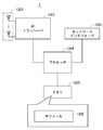
- FIG. 12 is a block diagram illustrating a configuration example of the NR NB1 according to the above-described embodiment.
- NR NB1 includes a Radio Frequency transceiver 1201, a network interface 1203, a processor 1204, and a memory 1205.
- the RF transceiver 1201 performs analog RF signal processing to communicate with NG UEs including UE2.
- the RF transceiver 1201 may include multiple transceivers.
- RF transceiver 1201 is coupled to antenna array 1202 and processor 1204.
- the RF transceiver 1201 receives modulation symbol data from the processor 1204, generates a transmission RF signal, and provides the transmission RF signal to the antenna array 1202. Further, the RF transceiver 1201 generates a baseband received signal based on the received RF signal received by the antenna array 1202, and supplies this to the processor 1204.
- the RF transceiver 1201 may include an analog beamformer circuit for beamforming.
- the analog beamformer circuit includes, for example, a plurality of phase shifters and a plurality of power amplifiers.
- the network interface 1203 is used to communicate with a network node (e.g., “NG” Core control node and forwarding node).
- the network interface 1203 may include, for example, a network interface card (NIC) compliant with IEEE 802.3 series.
- NIC network interface card
- the processor 1204 performs digital baseband signal processing (data plane processing) and control plane processing for wireless communication.
- the processor 1204 may include a plurality of processors.
- the processor 1204 includes a modem processor (eg, Digital Signal Processor (DSP)) that performs digital baseband signal processing and a protocol stack processor (eg, Central Processing Unit (CPU) or Micro Processing Unit (CPU) that performs control plane processing. MPU)).
- DSP Digital Signal Processor
- MPU Micro Processing Unit
- the processor 1204 may include a digital beamformer module for beamforming.
- the digital beamformer module may include a multiple-input-multiple-output (MIMO) encoder and a precoder.
- MIMO multiple-input-multiple-output
- the memory 1205 is configured by a combination of a volatile memory and a nonvolatile memory.
- the volatile memory is, for example, Static Random Access Memory (SRAM), Dynamic RAM (DRAM), or a combination thereof.
- the non-volatile memory is a mask Read Only Memory (MROM), Electrically Erasable Programmable ROM (EEPROM), flash memory, hard disk drive, or any combination thereof.
- Memory 1205 may include storage located remotely from processor 1204. In this case, the processor 1204 may access the memory 1205 via the network interface 1203 or an I / O interface not shown.
- the memory 1205 may store one or more software modules (computer programs) 1206 including an instruction group and data for performing processing by the NR NB1 described in the above embodiments.
- the processor 1204 may be configured to read and execute the software module 1206 from the memory 1205 to perform the processing of NR NB1 described in the above-described embodiment.
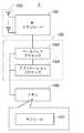
- FIG. 13 is a block diagram illustrating a configuration example of UE2.
- Radio-frequency (RF) transceiver 1301 performs analog RF signal processing to communicate with NR-NB1.
- the RF transceiver 1301 may include multiple transceivers.
- Analog RF signal processing performed by the RF transceiver 1301 includes frequency up-conversion, frequency down-conversion, and amplification.
- RF transceiver 1301 is coupled to antenna array 1302 and baseband processor 1303.
- the RF transceiver 1301 receives modulation symbol data (or OFDM symbol data) from the baseband processor 1303, generates a transmission RF signal, and supplies the transmission RF signal to the antenna array 1302.
- the RF transceiver 1301 generates a baseband received signal based on the received RF signal received by the antenna array 1302 and supplies this to the baseband processor 1303.
- the RF transceiver 1301 may include an analog beamformer circuit for beamforming.
- the analog beamformer circuit includes, for example, a plurality of phase shifters and a plurality of power amplifiers.
- the baseband processor 1303 performs digital baseband signal processing (data plane processing) and control plane processing for wireless communication.
- Digital baseband signal processing consists of (a) data compression / decompression, (b) data segmentation / concatenation, (c) ⁇ transmission format (transmission frame) generation / decomposition, and (d) transmission path encoding / decoding. , (E) modulation (symbol mapping) / demodulation, and (f) generation of OFDM symbol data (baseband OFDM signal) by Inverse Fast Fourier Transform (IFFT).
- control plane processing includes layer 1 (eg, transmission power control), layer 2 (eg, radio resource management, hybrid automatic repeat request (HARQ) processing), and layer 3 (eg, attach, mobility, and call management). Communication management).
- the digital baseband signal processing by the baseband processor 1303 may include signal processing of the Packet Data Convergence Protocol (PDCP) layer, Radio Link Control (RLC) layer, MAC layer, and PHY layer.
- the control plane processing by the baseband processor 1303 may include Non-Access-Stratum (NAS) protocol, RRC protocol, and MAC CE processing.
- PDCP Packet Data Convergence Protocol
- RLC Radio Link Control
- MAC Medium Access-Stratum
- MAC CE Non-Access-Stratum
- the baseband processor 1303 may perform MIMO encoding and precoding for beamforming.
- the baseband processor 1303 may include a modem processor (e.g., DSP) that performs digital baseband signal processing and a protocol stack processor (e.g., CPU or MPU) that performs control plane processing.
- a protocol stack processor e.g., CPU or MPU
- a protocol stack processor that performs control plane processing may be shared with an application processor 1304 described later.
- the application processor 1304 is also called a CPU, MPU, microprocessor, or processor core.
- the application processor 1304 may include a plurality of processors (a plurality of processor cores).
- the application processor 1304 is a system software program (Operating System (OS)) read from the memory 1306 or a memory (not shown) and various application programs (for example, call application, web browser, mailer, camera operation application, music playback)
- OS Operating System
- application programs for example, call application, web browser, mailer, camera operation application, music playback
- Various functions of UE2 are realized by executing (application).
- the baseband processor 1303 and the application processor 1304 may be integrated on a single chip, as indicated by the dashed line (1305) in FIG.
- the baseband processor 1303 and the application processor 1304 may be implemented as one System on Chip (SoC) device 1305.
- SoC System on Chip
- An SoC device is sometimes called a system Large Scale Integration (LSI) or chipset.
- the memory 1306 is a volatile memory, a nonvolatile memory, or a combination thereof.
- the memory 1306 may include a plurality of physically independent memory devices.
- the volatile memory is, for example, SRAM or DRAM or a combination thereof.
- the non-volatile memory is MROM, EEPROM, flash memory, or hard disk drive, or any combination thereof.
- the memory 1306 may include an external memory device accessible from the baseband processor 1303, the application processor 1304, and the SoC 1305.
- the memory 1306 may include an embedded memory device integrated within the baseband processor 1303, the application processor 1304, or the SoC 1305.
- the memory 1306 may include a memory in a Universal Integrated Circuit Card (UICC).
- UICC Universal Integrated Circuit Card
- the memory 1306 may store one or more software modules (computer programs) 1307 including an instruction group and data for performing processing by the UE 2 described in the plurality of embodiments.
- the baseband processor 1303 or the application processor 1304 is configured to read the software module 1307 from the memory 1306 and execute the software module 1307 to perform the processing of the UE 2 described with reference to the drawings in the above-described embodiment. May be.
- each of the processors included in NR NB1 and UE2 includes a group of instructions for causing a computer to execute the algorithm described with reference to the drawings. Alternatively, a plurality of programs are executed. The program can be stored and supplied to a computer using various types of non-transitory computer readable media. Non-transitory computer readable media include various types of tangible storage media (tangible storage medium).
- non-transitory computer-readable media are magnetic recording media (eg flexible disks, magnetic tapes, hard disk drives), magneto-optical recording media (eg magneto-optical discs), Compact Disc Read Only Memory (CD-ROM), CD-ROM R, CD-R / W, semiconductor memory (for example, mask ROM, Programmable ROM (PROM), Erasable PROM (EPROM), flash ROM, Random Access Memory (RAM)).
- the program may also be supplied to the computer by various types of temporary computer-readable media. Examples of transitory computer readable media include electrical signals, optical signals, and electromagnetic waves.
- the temporary computer-readable medium can supply the program to the computer via a wired communication path such as an electric wire and an optical fiber, or a wireless communication path.
- the UE 2 may aggregate a plurality of carriers respectively belonging to different frequency bands (e.g., 6 GHz band and 30 GHz band).
- the same numerology may be used for a plurality of carriers belonging to different frequency bands.
- NR NB1 and UE2 may support aggregation of a plurality of carriers belonging to different frequency bands and having the same numerology.
- the UE 2 or the NR1NB 1 may perform beam selection in a predetermined carrier set unit, that is, within the carrier set.
- the carrier set may be a plurality of carriers belonging to the same frequency band, for example.
- UE2 realizes Dual Connectivity (for example, conventional DC in Inter-RAT environment) between NR NB1 and LTE (or eLTE which is an advanced system thereof) eNB It may also be applied when performing functions that have been developed). For example, for UE2, when (e) LTE NB is operated as Master Node (M-NB) and NR NB1 is operated as Secondary Node (S-NB), it consists of one or more cells managed by NR NB1. A cell group may be used as a secondary cell group (SCG). At this time, the above-described embodiment may be applied to an SCG cell (group).
- M-NB Master Node
- S-NB Secondary Node
- a cell group may be used as a secondary cell group (SCG).
- SCG secondary cell group
- the above-described embodiment may be applied to an SCG cell (group).
- Multi-Connectivity is an operation that is configured so that UEs with multiple transceivers can use multiple radio resources provided by multiple (within RAN nodes) schedulers connected via non-ideal backhaul. It may be expressed as a mode.
- the beam (or beam set) may correspond to a network slice (NS) in network slicing.
- NS network slice
- a plurality of network slices that satisfy different service requirements may be set (or configured), and each network slice may be associated (associated) with each beam (or each beam set).
- the NR NB1 and the UE2 may operate to select a network slice corresponding to a service that the UE2 is executing (or scheduled to execute) and a beam (or beam set) corresponding thereto.
- a wireless terminal A radio transceiver configured to transmit signals to and receive signals from the base station; At least one processor; With The at least one processor comprises: Receiving beam setting information from the base station; Measuring a first plurality of transmit beams transmitted from the base station according to the beam setting information; Based on the measurement results of the first plurality of transmission beams, one or more beams selected from the first plurality of transmission beams are transmitted from the base station to the wireless terminal. Configured to be used as one serving beam, Each of the first plurality of transmit beams carries a beamformed reference signal measured by the wireless terminal; The beam setting information includes a reference signal setting indicating a radio resource used in each beam for transmission of the beamformed reference signal. Wireless terminal.
- Each of the first plurality of transmit beams carries a signal indicative of a beam identifier;
- the beam setting information indicates the beam identifier of each beam.
- the wireless terminal according to attachment 1.
- the at least one processor is configured to select the first serving beam from the first plurality of transmit beams based on measurement results of the first plurality of transmit beams;
- the beam setting information further includes a selection criterion for the first serving beam.
- the wireless terminal according to appendix 1 or 2.
- At least one of the selection of the first serving beam or the switching of the serving beam is performed in a Medium Access Control (MAC) sublayer.
- MAC Medium Access Control
- the at least one processor comprises: Transmitting beam information based on measurement results of the first plurality of transmit beams to the base station; Configured to receive a message from the base station indicating the first serving beam selected by the base station based on the beam information; The wireless terminal according to appendix 1 or 2.
- the at least one processor comprises: Measuring a second plurality of transmit beams transmitted from the base station; One or more beams selected from the second plurality of transmission beams based on the measurement results of the second plurality of transmission beams are used for transmission from the base station to the wireless terminal. Configured to be used as a second serving beam; The first plurality of transmit beams use a first carrier; The second plurality of transmit beams use a second carrier; The at least one processor is further configured to perform aggregation of the first carrier and the second carrier; The wireless terminal according to any one of appendices 1 to 5.
- the at least one processor switches the first serving beam among the first plurality of transmit beams belonging to the first carrier and belongs to the second carrier during the execution of the aggregation Configured to switch the second serving beam between the second plurality of transmit beams;
- the wireless terminal according to attachment 6.
- the at least one processor is responsive to the second carrier in response to triggering switching of the first serving beam between the first plurality of transmit beams belonging to the first carrier. Configured to switch the second serving beam among the second plurality of transmit beams to which it belongs, The wireless terminal according to appendix 6 or 7.
- the at least one processor comprises: To provide one Medium Access Control (MAC) entity that performs downlink reception on both the first serving beam belonging to the first carrier and the second serving beam belonging to the second carrier. It is configured, The wireless terminal according to any one of appendices 6 to 8.
- MAC Medium Access Control
- the MAC entity suspends or stops at least part of the MAC layer processing for the first carrier when the serving beam of the first carrier is switched, but for the second carrier Configured to continue the MAC layer processing of The wireless terminal according to appendix 9.
- the at least one processor comprises: A first MAC entity that performs downlink reception on the first serving beam belonging to the first carrier and a second that performs downlink reception on the second serving beam belonging to the second carrier Configured to provide a Medium Access Control (MAC) entity, The wireless terminal according to any one of appendices 6 to 8.
- MAC Medium Access Control
- the first MAC entity is configured to perform MAC reset, configuration information update, or reconfiguration when a serving beam of the first carrier is switched,
- the second MAC entity is configured to continue MAC layer processing regardless of switching of the serving beam of the first carrier;
- the wireless terminal according to attachment 11.
- the frequency band including the first carrier is different from the frequency band including the second carrier.
- the wireless terminal according to any one of appendices 6 to 12.
- the first carrier and the second carrier are different from each other in at least one of a subcarrier spacing, a symbol length, a transmission time interval (TTI), and a subframe duration. , 14.
- the wireless terminal according to any one of appendices 6 to 13.
- the first plurality of transmit beams carry signals indicative of the same cell identifier or the same group identifier; 15.
- the wireless terminal according to any one of appendices 1 to 14.
- a base station At least one wireless transceiver configured to transmit signals to and receive signals from the wireless terminals; At least one processor; With The at least one processor comprises: Send beam setting information to the wireless terminal, One or more beams selected from the first plurality of transmission beams based on a measurement result by the wireless terminal of the first plurality of transmission beams transmitted from the base station are transmitted from the base station. Configured to be used as a first serving beam for transmission to the wireless terminal; Each of the first plurality of transmit beams carries a beamformed reference signal measured by the wireless terminal; The beam setting information includes a reference signal setting indicating a radio resource used in each beam for transmission of the beamformed reference signal. base station.
- the at least one processor is configured to receive a message from the wireless terminal indicating the first serving beam selected by the wireless terminal based on a measurement result of the first plurality of transmit beams.
- the base station according to attachment 16.
- the at least one processor comprises: Receiving beam information from the wireless terminal based on measurement results of the first plurality of transmit beams; Selecting the first serving beam from the first plurality of transmit beams based on the beam information; Configured to transmit a message indicating the first serving beam selected by the base station to the wireless terminal; The base station according to attachment 16.
- the at least one processor comprises: One or more beams selected from the second plurality of transmission beams based on a measurement result by the wireless terminal of the second plurality of transmission beams transmitted from the base station are transmitted from the base station. Configured to be used as a second serving beam for transmission to the wireless terminal; The first plurality of transmit beams use a first carrier; The second plurality of transmit beams use a second carrier; The at least one processor is further configured to perform aggregation of the first carrier and the second carrier; The base station according to any one of appendices 16 to 18.
- the at least one processor switches the first serving beam among the first plurality of transmit beams belonging to the first carrier and belongs to the second carrier during the execution of the aggregation Configured to switch the second serving beam between the second plurality of transmit beams;
- the base station according to appendix 19.
- the at least one processor is responsive to the second carrier in response to triggering switching of the first serving beam between the first plurality of transmit beams belonging to the first carrier. Configured to switch the second serving beam among the second plurality of transmit beams to which it belongs, The base station according to appendix 19 or 20.
- the at least one processor comprises: To provide one Medium Access Control (MAC) entity that performs downlink transmission on both the first serving beam belonging to the first carrier and the second serving beam belonging to the second carrier. It is configured, The base station according to any one of appendices 19 to 21.
- MAC Medium Access Control
- the MAC entity suspends or stops at least part of the MAC layer processing for the first carrier when the serving beam of the first carrier is switched, but for the second carrier Configured to continue the MAC layer processing of The base station according to attachment 22.
- the at least one processor comprises: A first MAC entity that performs downlink transmission on the first serving beam belonging to the first carrier and a second that performs downlink transmission on the second serving beam belonging to the second carrier Configured to provide a Medium Access Control (MAC) entity, The base station according to any one of appendices 19 to 21.
- MAC Medium Access Control
- the first MAC entity is configured to perform MAC reset, configuration information update, or reconfiguration when a serving beam of the first carrier is switched,
- the second MAC entity is configured to continue MAC layer processing regardless of switching of the serving beam of the first carrier;
- the base station according to attachment 24.
- the first carrier and the second carrier are different from each other in at least one of a subcarrier spacing, a symbol length, a transmission time interval (TTI), and a subframe duration.
- the base station according to any one of appendices 19 to 25.
- the at least one transceiver includes a plurality of distributed Remote Radio Heads (RRHs) or Transmission and Reception Points (TRPs); The base station according to any one of appendices 16 to 26.
- RRHs Remote Radio Heads
- TRPs Transmission and Reception Points
- (Appendix 28) A method performed by a wireless terminal, Receiving beam setting information from the base station; Measuring a first plurality of transmission beams transmitted from the base station according to the beam setting information; and, based on a measurement result of the first plurality of transmission beams, out of the first plurality of transmission beams.
- Each of the first plurality of transmit beams carries a beamformed reference signal measured by the wireless terminal;
- the beam setting information includes a reference signal setting indicating a radio resource used in each beam for transmission of the beamformed reference signal.
- a method in a base station Transmitting beam setting information to the wireless terminal, and selected from the first plurality of transmission beams based on a measurement result of the first plurality of transmission beams transmitted from the base station by the wireless terminal Using one or more beams as a first serving beam for transmission from the base station to the wireless terminal; With Each of the first plurality of transmit beams carries a beamformed reference signal measured by the wireless terminal;
- the beam setting information includes a reference signal setting indicating a radio resource used in each beam for transmission of the beamformed reference signal.
- (Appendix 30) A program for causing a computer to perform a method in a wireless terminal, The method Receiving beam setting information from the base station; Measuring a first plurality of transmission beams transmitted from the base station according to the beam setting information; and, based on a measurement result of the first plurality of transmission beams, out of the first plurality of transmission beams.
- the beam setting information includes a reference signal setting indicating a radio resource used in each beam for transmission of the beamformed reference signal. program.
- a program for causing a computer to perform a method in a base station The method Transmitting beam setting information to the wireless terminal, and selected from the first plurality of transmission beams based on a measurement result of the first plurality of transmission beams transmitted from the base station by the wireless terminal Using one or more beams as a first serving beam for transmission from the base station to the wireless terminal; With Each of the first plurality of transmit beams carries a beamformed reference signal measured by the wireless terminal;
- the beam setting information includes a reference signal setting indicating a radio resource used in each beam for transmission of the beamformed reference signal. program.
Landscapes
- Engineering & Computer Science (AREA)
- Signal Processing (AREA)
- Computer Networks & Wireless Communication (AREA)
- Quality & Reliability (AREA)
- Mobile Radio Communication Systems (AREA)
Abstract
無線端末(2)は、ビーム設定情報を基地局(1)から受信し、基地局(1)から送信される複数の送信ビーム(10)をビーム設定情報に従って測定し、当該測定の結果に基づいて複数の送信ビーム(10)の中から選択された1又はそれ以上のビームをサービングビームとして使用する。複数の送信ビームの各々は、無線端末(2)によって測定されるビームフォームド参照信号を運ぶ。ビーム設定情報は、ビームフォームド参照信号の送信のために各ビームにおいて使用される無線リソースを示す参照信号設定を含む。これにより、例えば、ビーム間のUEモビリティのための手順の提供に寄与できる。
Description
本開示は、無線通信に関し、特に指向性ビームを使用する無線通信に関する。
3rd Generation Partnership Project(3GPP)は、2020年移行の導入に向けた第5世代移動通信システム(5G)の標準化作業を3GPP Release 14として2016年に開始している。5Gは、LTE及びLTE-Advancedの継続的な改良・発展(enhancement/evolution)と新たな5Gエア・インタフェース(新たなRadio Access Technology(RAT))の導入による革新的な改良・発展の組合せで実現されると想定されている。新たなRATは、例えば、LTE/LTE-Advancedの継続的発展が対象とする周波数帯(e.g., 6 GHz以下)よりも高い周波数帯、例えば10 GHz以上のセンチメートル波帯及び30 GHz以上のミリ波帯をサポートする。
本明細書では、第5世代移動通信システムは、Next Generation (NextGen) System(NG System)とも呼ばれる。NG Systemのための新たなRATは、New Radio(NR)、5G RAT、又はNG RATと呼ばれる。NG Systemのための新たな無線アクセスネットワーク(Radio Access Network(RAN))及びコアネットワークは、それぞれNextGen RAN(NG RAN)又はNew RAN、及びNextGen Core(NG Core)と呼ばれる。NG Systemに接続する無線端末(User Equipment(UE))は、NextGen UE(NG UE)と呼ばれる。New Radio(NR)をサポートする基地局は、NG NodeB(NG NB)、NR NodeB(NR NB)、又はgNBと呼ばれる。NG SystemのためのRAT、UE、無線アクセスネットワーク、コアネットワーク、ネットワーク・エンティティ(ノード)、及びプロトコルレイヤ等の正式な名称は、標準化作業が進む過程で将来的に決定されるであろう。
また、本明細書で使用される“LTE”との用語は、特に断らない限り、NG Systemとのインターワーキングを可能とするためのLTE及びLTE-Advancedの改良・発展を含む。NG System とのインターワークのためのLTE及びLTE-Advancedの改良・発展は、LTE-Advanced Pro、LTE+、又はenhanced LTE(eLTE)とも呼ばれる。さらに、本明細書で使用される“Evolved Packet Core (EPC)”、“Mobility Management Entity (MME)”、“Serving Gateway (S-GW)”、及び“Packet Data Network (PDN) Gateway (P-GW)”等のLTEのネットワーク又は論理的エンティティに関する用語は、特に断らない限り、NG Systemとのインターワーキングを可能とするためのこれらの改良・発展を含む。改良されたEPC、MME、S-GW、及びP-GWは、例えば、enhanced EPC(eEPC)、enhanced MME(eMME)、enhanced S-GW(eS-GW)、及びenhanced P-GW(eP-GW)とも呼ばれる。
上述のように、NGシステムは高周波数帯(higher frequency band)(e.g., 6 GHz以上)をサポートする。高周波数帯において所望のカバレッジを確保するには、伝搬損失(path loss)を補償するために高いアンテナゲインが必要とされる。一方で、アンテナ素子の大きさは波長に比例して小さくなるため、高周波数帯では非常に多数のアンテナ素子(e.g., 数百個のアンテナ素子)を用いたマルチアンテナを現実的な大きさのアンテナによって実現できる。したがって、NG Systemでは、高利得ビーム(high gain beams)を形成するために大規模アンテナアレイ(larger antenna arrays)が使用される。ビームは、少なくともいくつかのレベルの指向性を有する放射パターン(radiation pattern)を意味する。高利得ビームは、低周波数帯(lower frequency bands)(e.g., 現在のLTE bands(6 GHz以下))において使用される広いセクタビーム(wide sector beam)に比べて狭い(narrow)。したがって、所望のセルエリアをカバーするために複数のビーム(multiple beams)が必要とされる。
NR NBは、複数のTransmission and Reception Points(TRPs)を使用してもよい。TRPは、無線信号(radio signals)の送信及び受信のための物理的位置を意味する。TRPsは、集中化されて配置されてもよいし、分散されて配置されてもよい。各TRPは、複数のビームを形成してもよい。TRPは、remote radio head (RRH)と呼ぶこともできる。
NRシステムにおけるビーム関連手順(beam related procedures)に関する提案がなされている(例えば、非特許文献1-6を参照)。ビーム関連手順は、モビリティ(手順)及びビーム管理(手順)を含む(非特許文献6)。ビーム管理(beam management)は、下りリンク(DL)及び上りリンク(UL)送信/受信に使用されることができるTRP(s)及び/又はUE beamsを獲得(acquire)及び維持(maintain)するためのレイヤ1(L1)/レイヤ2(L2)手順のセットである。ビーム管理は、少なくとも、ビーム決定(beam determination)、ビーム測定(beam measurement)、ビーム報告(beam reporting)、及びビーム掃引(beam sweeping)を含む。ビーム決定は、TRP(s)又はUEがそれ自身の送信/受信ビーム(its own Tx/Rx beam(s))を選択するための手順である。ビーム測定は、TRP(s)又はUEが受信ビームフォームド信号の特性(characteristics)を測定するための手順である。ビーム報告は、UEがビーム測定に基づくビームフォームド信号(signal(s))の情報を報告するための手順である。ビーム掃引は、予め定められた方法で(in a predetermined way)タイムインターバルの間に送信及び/又は受信されるビーム(beams)によって空間領域(a spatial area)をカバーする操作(operation)である。
また、NRは複数の周波数バンドに異なる無線パラメータセットを使用することが想定されている。例えば、サブキャリア間隔(spacing)、シンボル長(symbol length)、Transmission Time Interval(TTI)、及びサブフレーム期間(subframe duration)が周波数バンドによって異なる。これらの無線パラメータセットは、numerologyと呼ばれる。NGシステムでは、UE及びNR NBは、異なるnumerologiesの複数のNRキャリアのアグリゲーションをサポートする。3GPPでは、異なるnumerologiesの複数のNRキャリアのアグリゲーションが既存のLTE Carrier Aggregation(CA)のような低レイヤ・アグリゲーション(lower layer aggregation)又は既存のDual Connectivityのような高レイヤ・アグリゲーション(upper layer aggregation)によって実現されることが検討されている(例えば、非特許文献7-9を参照)。
3GPP technical document R2-163437, Nokia, Alcatel-Lucent Shanghai Bell, "Beam Terminology", 3GPP TSG-RAN WG2 Meeting #94, Nanjing, China, 23-27 May 2016
3GPP technical document R2-163443, Nokia, Alcatel-Lucent Shanghai Bell, "On beam sweeping and its implications", 3GPP TSG-RAN WG2 Meeting #94, Nanjing, China, 23-27 May 2016
3GPP technical document R2-163476, Nokia, Alcatel-Lucent Shanghai Bell, "Beam management in NR", 3GPP TSG-RAN WG2 Meeting #94, Nanjing, China, 23-27 May 2016
3GPP technical document R2-163579, Intel Corporation, "Mobility and beam support in NR", 3GPP TSG-RAN WG2 Meeting #94, Nanjing, China, 23-27 May 2016
3GPP technical document R2-163712, Samsung, "Use cases and RAN2 issues of beam tracking in a beamforming based high frequency NR", 3GPP TSG-RAN WG2 Meeting #94, Nanjing, China, 23-27 May 2016
3GPP technical document R1-168468, Nokia, Qualcomm, CATT, Intel, NTT DoCoMo, Mediatek, Ericsson, ASB, Samsung, LG, "Definitions supporting beam related procedures", 3GPP TSG RAN WG1 Meeting #86, Gothenburg, Sweden, 22-26 August 2016
3GPP TR 38.804 V0.3.0 (2016-08) "3rd Generation Partnership Project; Technical Specification Group Radio Access Network; Study on New Radio Access Technology; Radio Interface Protocol Aspects (Release 14)", August 2016
3GPP technical document R2-164788, Nokia, Alcatel-Lucent Shanghai Bell, "Carrier Aggregation between carriers of different air interface numerologies", 3GPP TSG-RAN WG2 Meeting #95, Gothenburg, Sweden, 22-26 August 2016
3GPP technical document R2-165328, "Aggregation of carriers in NR", 3GPP TSG-RAN WG2 Meeting #95, Gothenburg, Sweden, 22-26 August 2016
本件発明者は、ビーム間のUEモビリティについて検討し幾つかの課題を見出した。本明細書に開示される実施形態が達成しようとする目的の1つは、ビーム間のUEモビリティのための手順の提供に寄与する装置、方法、及びプログラムを提供することである。なお、この目的は、本明細書に開示される複数の実施形態が達成しようとする複数の目的の1つに過ぎないことに留意されるべきである。その他の目的又は課題と新規な特徴は、本明細書の記述又は添付図面から明らかにされる。
第1の態様では、無線端末は、無線トランシーバ及び少なくとも1つのプロセッサを含む。前記無線トランシーバは、基地局に信号を送信し、前記基地局から信号を受信するよう構成されている。前記少なくとも1つのプロセッサは、ビーム設定情報を前記基地局から受信し、前記基地局から送信される第1の複数の送信ビームを前記ビーム設定情報に従って測定するよう構成されている。前記少なくとも1つのプロセッサは、さらに、前記第1の複数の送信ビームの測定結果に基づいて前記第1の複数の送信ビームの中から選択された1又はそれ以上のビームを、前記基地局から前記無線端末への送信のための第1のサービングビームとして使用するよう構成されている。前記第1の複数の送信ビームの各々は、前記無線端末によって測定されるビームフォームド参照信号を運ぶ。前記ビーム設定情報は、前記ビームフォームド参照信号の送信のために各ビームにおいて使用される無線リソースを示す参照信号設定を含む。
第2の態様では、基地局は、無線トランシーバ及び少なくとも1つのプロセッサを含む。前記無線トランシーバは、無線端末に信号を送信し、前記無線端末から信号を受信するよう構成されている。前記少なくとも1つのプロセッサは、ビーム設定情報を無線端末に送信するよう構成されている。前記少なくとも1つのプロセッサは、さらに、前記基地局から送信される第1の複数の送信ビームの前記無線端末による測定結果に基づいて前記第1の複数の送信ビームの中から選択された1又はそれ以上のビームを、前記基地局から前記無線端末への送信のための第1のサービングビームとして使用するよう構成されている。前記第1の複数の送信ビームの各々は、前記無線端末によって測定されるビームフォームド参照信号を運ぶ。前記ビーム設定情報は、前記ビームフォームド参照信号の送信のために各ビームにおいて使用される無線リソースを示す参照信号設定を含む。
第3の態様では、無線端末により行われる方法は、(a)ビーム設定情報を前記基地局から受信すること、(b)前記基地局から送信される第1の複数の送信ビームを前記ビーム設定情報に従って測定すること、及び(c)前記第1の複数の送信ビームの測定結果に基づいて前記第1の複数の送信ビームの中から選択された1又はそれ以上のビームを、前記基地局から前記無線端末への送信のための第1のサービングビームとして使用すること、を含む。前記第1の複数の送信ビームの各々は、前記無線端末によって測定されるビームフォームド参照信号を運ぶ。前記ビーム設定情報は、前記ビームフォームド参照信号の送信のために各ビームにおいて使用される無線リソースを示す参照信号設定を含む。
第4の態様では、基地局により行われる方法は、(a)ビーム設定情報を無線端末に送信すること、及び(b)前記基地局から送信される第1の複数の送信ビームの前記無線端末による測定結果に基づいて前記第1の複数の送信ビームの中から選択された1又はそれ以上のビームを、前記基地局から前記無線端末への送信のための第1のサービングビームとして使用することを含む。前記第1の複数の送信ビームの各々は、前記無線端末によって測定されるビームフォームド参照信号を運ぶ。前記ビーム設定情報は、前記ビームフォームド参照信号の送信のために各ビームにおいて使用される無線リソースを示す参照信号設定を含む。
第5の態様では、プログラムは、コンピュータに読み込まれた場合に、上述の第3又は第4の態様に係る方法をコンピュータに行わせるための命令群(ソフトウェアコード)を含む。
上述の態様によれば、ビーム間のUEモビリティのための手順の提供に寄与する装置、方法、及びプログラムを提供できる。
以下では、具体的な実施形態について、図面を参照しながら詳細に説明する。各図面において、同一又は対応する要素には同一の符号が付されており、説明の明確化のため、必要に応じて重複説明は省略される。
以下に説明される複数の実施形態は、独立に実施されることもできるし、適宜組み合わせて実施されることもできる。これら複数の実施形態は、互いに異なる新規な特徴を有している。したがって、これら複数の実施形態は、互いに異なる目的又は課題を解決することに寄与し、互いに異なる効果を奏することに寄与する。
<第1の実施形態>
図1~図4は、本実施形態に係る無線通信ネットワークのいくつかの構成例及びビームレベルモビリティのいくつかの例を示す図である。図1の例では、無線通信ネットワークは、New Radio (NR) 基地局(i.e., NR NodeB (NR NB))1及び無線端末(UE)2を含む。NR NB1は、複数の送信ビーム10を形成し、各送信ビームにおいてビームフォームド参照信号(beamformed Reference Signal (RS))を送信する。言い換えると、各送信ビーム10は、ビームフォームド参照信号を運ぶ。ビームフォームド参照信号は、beam-specific reference signal(BRS)と呼ぶこともできる。ビームフォームド参照信号は、プリコードされたChannel State Information (CSI) 参照信号(precoded CSI-RS)であってもよい。ビームフォームド参照信号は、UE特有(UE-specific)でもよいし、UE非特有(non-UE-specific)でもよい。
図1~図4は、本実施形態に係る無線通信ネットワークのいくつかの構成例及びビームレベルモビリティのいくつかの例を示す図である。図1の例では、無線通信ネットワークは、New Radio (NR) 基地局(i.e., NR NodeB (NR NB))1及び無線端末(UE)2を含む。NR NB1は、複数の送信ビーム10を形成し、各送信ビームにおいてビームフォームド参照信号(beamformed Reference Signal (RS))を送信する。言い換えると、各送信ビーム10は、ビームフォームド参照信号を運ぶ。ビームフォームド参照信号は、beam-specific reference signal(BRS)と呼ぶこともできる。ビームフォームド参照信号は、プリコードされたChannel State Information (CSI) 参照信号(precoded CSI-RS)であってもよい。ビームフォームド参照信号は、UE特有(UE-specific)でもよいし、UE非特有(non-UE-specific)でもよい。
複数の送信ビーム10は、ビーム識別子(beam identifier(beam ID))によって特定される。言い換えると、複数の送信ビーム10は、異なるビームIDによって互いに区別される。ビームIDは、ビームインデックスと呼ぶこともできる。ビームフォームド参照信号は、ビーム識別子を含んでもよい。これに代えて、ビームIDは、ビームフォームド参照信号の送信に使用される無線リソース(e.g., サブキャリア、タイムスロット、リソースブロック、若しくは拡散コード又はこれらの任意の組合せ)、又は当該無線リソース(の組み合わせ)に予め紐付けられたインデックスによって特定されてもよい。1つのTRPが1つの送信ビームのみを形成する場合、ビーム識別子はTRP識別子(TRP ID)であってもよい。言い換えると、ビーム識別子の代わりに、複数の送信ビーム10を区別するためにTRP識別子が使用されてもよい。
複数の送信ビーム10の複数のビームIDは、NR NB1によって提供される同じセル識別子(e.g., E-UTRAN Cell Global ID(ECGI)、Physical Cell Identifier(PCI))に関連付けられてもよい。言い換えると、同じセルをカバーする複数の送信ビーム10は、同じセル識別子に関連付けられてもよい。
UE2は、NR NB1が管理するいずれかのセルにおいて、NR NB1からビーム設定情報を受信し、NR NB1の複数の送信ビーム10をビーム設定情報に従って測定する。ビーム設定情報は、ビームフォームド参照信号の送信のために各送信ビーム10において使用される無線リソースを示す参照信号設定を含む。NR NB1及びUE2は、UE2による複数の送信ビームの測定結果に基づいて複数の送信ビーム10の中から選択された1又はそれ以上のビームを、NR NB1からUE2への送信のためのサービングビームとして使用する。UE2による複数の送信ビームの測定結果に基づくサービングビームの選択(又は決定)は、UE2によって行われてもよいし、NR NB1によって行われてもよい。
例えば、NR NB1は、ビーム形成を行わない又は広いセクタビームを用いる低周波数帯のセルにおいて、高周波数帯の他のセルの複数の送信ビーム10に関するビーム設定情報を送信してもよい。低周波数帯のセルは、(e)LTE マクロセルであってもよく、NR NB1とUE2の間の制御コネクションを維持するために使用されてもよい。これに代えて、ビーム設定情報は、すでに選択(設定)されたサービングビームにおいてNR NB1からUE2へ送信されてもよい。サービングビームで送信されたビーム設定情報が、当該サービングビームの測定並びに他の送信ビームの測定及び(再)選択に用いられてもよい。
ビーム設定情報は、ビーム設定セット情報要素(beam configuration set information element (IE))を含んでもよい。ビーム設定情報は、NR NB1によってブロードキャストされるシステム情報(System Information Block(SIB))に含まれてもよいし、個別(dedicated)Radio Resource Control(RRC)シグナリングによってUE2に送られてもよい。あるいは、UE2が本実施形態に係るビームフォーミング機能を有しており、NR NB1がUE2のサービングセルにおいて当該ビームフォーミング機能をサポートしている(有効にしている)場合、UE2がNR NB1にビーム設定情報を送信するように要求してもよい。UE2からの当該要求に応答して、NR NB1は、ビーム設定情報を報知してもよいし、UE2へ個別RRCシグナリング(dedicated RRC signaling)でビーム設定情報を送信してもよい。
ビーム設定情報は、さらに、ビーム識別子(e.g., beam ID, TRP ID)を含んでもよい。ビーム設定情報は、各ビーム又は各ビームの送信に使用されるTRP(又はRRH)に対応するエリア設定を含んでもよい。エリア設定は、ビーム識別子に関連付けられた地理的エリア(e.g., ゾーン、ビームエリア、予め定義されたセルの部分的エリア(cell portion))を示してもよい。エリア設定は、地理的エリアを示す情報として、緯度(latitude)、経度(longitude)の情報を含んでいてもよい。
UE2がビーム選択(又はビーム決定)を行う場合、ビーム設定情報はビーム選択基準(又はビーム決定基準)を含んでもよい。ビーム選択基準は、例えば、ビーム測定により得られるビームフォームド参照信号の受信品質(e.g., 受信信号強度(e.g., Reference Signal Received Power(RSRP))、受信信号品質(e.g., Reference Signal Received Quality(RSRQ))、Signal to Noise Ratio(SNR)、又はSignal to Interference-pulse-Noise Ratio(SINR))に適用される閾値又はオフセットを含んでもよい。
NR NB1がビーム選択を行う場合、ビーム設定情報は、ビーム報告基準を含んでもよい。ビーム報告基準は、例えば、ビーム測定により得られるビームフォームド参照信号の受信品質(e.g., 受信信号強度、SNR、又はSINR)に適用される閾値又はオフセットを含んでもよい。
ビーム設定情報は、ビームパターンに関するビーム・サブフレーム設定情報(beam subframe configuration)を含んでもよい。高周波数帯(higher frequency band)では、NR NB1が同時に送信できるビームの数は、所望のセルエリアをカバーするために必要なビーム数よりも少ないかもしれない。この場合、NR NB1は、所望のセルエリアをカバーするためにビーム掃引(sweeping)を行ってもよい。すなわち、NR NB1は、セル内の異なるエリアをカバーする複数のビーム・セットを順番にアクティブ化することによって、時間ドメインにおいてセルエリアを掃引する。ここで、ビーム・セットは、NR NB1によって同時に形成される1又は複数の送信ビーム10を意味する。
ビーム・サブフレーム設定情報は、NR NB1によるビーム掃引(sweeping)の設定情報(beam sweeping configuration)を含んでもよい。ビーム掃引の設定情報は、時間ドメインのビーム掃引(sweeping)のパターン(sweeping pattern)を含んでもよい。ビーム掃引(sweeping)パターンは、例えばビームIDが付与された送信ビーム毎に(図1の例ではN個の送信ビーム10それぞれに)、OFDMシンボル、複数のOFDMシンボルからなるスロット、サブフレーム、及びフレームのいずれかを単位とするビットマップ形式、又はそれらの組み合わせによって示されてもよい。例えば、ビットマップの”1”(又は”0”)が、当該送信ビームを使用して信号が送信されることを示してもよい。
時間ドメインのビーム掃引(sweeping)に加えて、又はこれに代えて、ビーム・サブフレーム設定情報(beam subframe configuration)は、周波数ドメインにおけるビームパターンの情報を含んでもよい。例えば、複数の周波数リソース(e.g., Subcarrier, Physical Resource Block: PRB。掃引ブロック)単位で、ビーム・セットが設定されてもよい。つまり、複数の周波数リソース毎に異なるビームを使用して信号が送信されてもよい。1つの掃引ブロックは、1つのアクティブなビームを用いてセル内の特定のエリアをカバーする。
図2の例では、NR NB1は、複数のTRP101A及び101Bを使用する。各TRP101は、1又はそれ以上の送信ビーム10を形成する。図2の例では、UE2は、1つのTRP101内の複数の送信ビーム10の間で移動する。図2の例では、ビーム設定情報は、1つのTRP101内の複数の送信ビーム10に関する設定を含んでもよい。
図3の例では、NR NB1は、複数のTRP101A及び101Bを使用する。各TRPは、1又はそれ以上の送信ビーム10を形成する。図3の例では、UE2は、TRP101Aによって形成される送信ビーム10AからTRP101Bによって形成される送信ビーム10Bに移動する。図3の例では、ビーム設定情報は、NR NB1によって管理される各TRP101によって形成される1又はそれ以上の送信ビーム10に関する設定を含んでもよい。
図4の例では、NR NB1は、複数のTRP101を用いて複数のキャリア(i.e., キャリア#1、#2、及び#3)を提供する。図4の例では、3つのキャリア#1、#2、及び#3のカバレッジは、実質的に同じ地理的エリアに階層的に形成される。UE2は、複数のキャリアのアグリゲーションをサポートする。NR NB1によって提供される複数のキャリアは、異なる周波数バンドに属してもよく、異なるnumerologies(e.g., サブキャリア間隔(spacing)、シンボル長(symbol length)、Transmission Time Interval(TTI)、及びサブフレーム期間(subframe duration))を使用してもよい。図4の例では、TRP101Aは、5 GHz帯のキャリア#1(i.e., セル#1)を運用し、キャリア#1の複数の送信ビーム10Aを形成し、TRP101Bは、5 GHz帯のキャリア#2(i.e., セル#2)を運用し、キャリア#2の複数の送信ビーム10Bを形成する。一方、TRP101Cは、30 GHz帯のキャリア#3(i.e., セル#3)を運用し、キャリア#3の複数の送信ビーム10Cを形成する。既に述べたように、高周波数帯において所望のカバレッジを確保するには、伝搬損失(path loss)を補償するために高いアンテナゲインが必要とされる。したがって、30 GHz帯のキャリア#3によって5 GHz帯のキャリア#1及び#2と同等のセルエリアをカバーするために、30 GHz帯の送信ビーム10Cのビーム幅は、5 GHz帯の送信ビーム10A及び10Bのビーム幅に比べて狭い。
図4の例では、UE2又はNR NB1は、キャリア単位で、つまり各キャリア内で、ビーム選択を行ってもよい。すなわち、UE2又はNR NB1は、キャリア#1内の複数の送信ビームからのサービングビーム選択、キャリア#2内の複数の送信ビームからのサービングビーム選択、及びキャリア#3内の複数の送信ビームからのサービングビーム選択をそれぞれ独立に行ってもよい。これに代えて、UE2又はNR NB1は、所定のキャリアセット単位で、つまりキャリアセット内で、ビーム選択を行ってもよい。キャリアセットは、同じ周波数バンドに属する複数のキャリア(e.g., キャリア#1及びキャリア#2)であってもよい。これに代えて、キャリアセットは、同じnumerologyが使用される複数のキャリアであってもよい。これに代えて、キャリアセットは、所定の基準に基づいて同様に取り扱われる複数のnumerologiesが使用される複数のキャリアであってもよい。図4の例では、ビーム設定情報は、NR NB1によって管理される各TRP101によって形成される1又はそれ以上の送信ビーム10に関する設定を含んでもよい。
図5は、ビーム間のUEモビリティのための手順の一例を示すシーケンス図である。図5の例では、UE2がサービングビームを選択する。ステップ501では、NR NB1は、UE2にビーム設定(beam configuration)を送信する。ステップ502では、NR NB1及びUE2は、最初のビーム選択(initial beam selection)を行う。最初のビーム選択では、NR NB1がUE2のためのサービングビームを指定してもよい。これに代えて、後述するビーム(再)選択と同様に、UE2が最初のサービングビームを選択してもよい。
ステップ503では、UE2は、ビーム設定に従って、NR NB1から送信される送信ビームの測定を行う。具体的には、UE2は、ビーム設定で指定された1又はそれ以上の送信ビームにそれぞれ対応する1又はそれ以上のビームフォームド参照信号の受信を試行し、受信されたビームフォームド参照信号の受信品質を測定する。UE2は、ビームフォームド参照信号の受信信号強度、SNR、又はSINR)を測定してもよい。
ステップ504では、UE2は、ビーム報告(beam reporting)をNR NB1に送る。ビーム報告は、ステップ503での測定結果に基づくビーム情報を含む。一例において、当該ビーム情報は、UE2により測定された全てのビームフォームド参照信号の受信品質を示してもよい。これに代えて、当該ビーム情報は、UE2による受信品質が閾値を超えるビームフォームド参照信号の受信品質若しくはビームID又はこれらの組合せを示してもよい。なお、図5の例ではUE2がサービングビームを選択するため、ステップ504のビーム報告は省略されてもよい。
続いて、UE2及びNR NB1は、図5に示されたオプションA1(i.e.,ステップ505及び506)、オプションA2(i.e.,ステップ507及び508)、及びオプションA3(i.e.,ステップ509及び510)のうちいずれか1つを実行する。
オプションA1では、RRCレイヤがビーム選択に関与せず、UE2のMedium Access Control(MAC)サブレイヤがビーム選択を行う。具体的には、ステップ505では、UE2は、サービングビームの選択をMACサブレイヤにおいて行う。UE2は、ステップ501のビーム設定に含まれるビーム選択基準に基づいて、サービングビームを選択してもよい。既に述べたように、ビーム選択基準は、ビームフォームド参照信号の受信品質に適用される閾値又はオフセットを含んでもよい。例えば、UE2は、ある送信ビームのビームフォームド参照信号の受信品質が現在のサービングビームのビームフォームド参照信号の受信品質よりも所定の閾値を超えて大きい場合、当該送信ビームを新たなサービングビームとして選択してもよい。ステップ506では、UE2は、UE2によって新たに選択されたサービングビームを示すMACレイヤ・メッセージ(beam indicationメッセージ)をNR NB1に送信する。当該MACレイヤ・メッセージは、NR NB1のMACサブレイヤにより処理される。当該MACレイヤ・メッセージは、MAC Control Element(CE)であってもよい。
オプションA2では、UE2のMACサブレイヤがビーム選択を行い、UE2のRRCレイヤが選択されたビームをNR NB1に通知する。具体的には、ステップ507では、UE2は、サービングビームの選択をMACサブレイヤにおいて行う。ステップ507での処理は、上述のステップ505での処理と同様であってもよい。ステップ508では、UE2は、UE2によって新たに選択されたサービングビームをRRCシグナリングによってNR NB1に知らせる。
オプションA3では、UE2のRRCレイヤがUE2のMACサブレイヤにビーム選択をトリガーし、UE2のRRCレイヤ又はMACサブレイヤが選択されたビームをNR NB1に通知する。具体的には、ステップ509では、UE2のMACサブレイヤは、UE2のRRCレイヤによってトリガーされたサービングビームの選択処理を実行する。ステップ510では、UE2は、UE2によって新たに選択されたサービングビームをRRCシグナリング又はMACサブレイヤ・メッセージ(e.g., MAC CE)によってNR NB1に知らせる。
ステップ511では、NR NB1は、ステップ506、508、又は510のbeam indicationメッセージの受信に応じて、応答メッセージ(beam indication acknowledgeメッセージ)をUE2に送信する。ステップ511の応答メッセージの送信は省略されてもよい。
ステップ512では、UE2及びNR NB1は、NR NB1からUE2への送信のためのサービングビームを、現在のビームからUE2により選択された新たなビームに切り替える。ステップ512の処理は、MACサブレイヤ及び物理(PHY)レイヤにおいて行われる。UE2のMACサブレイヤは、サービングビームの切り替え(switching)をUE2のPHYレイヤに指示する。(サービング)ビームの切り替え(switching)は、(サービング)ビームの変更(changing)と表現することもできるし、(サービング)ビームの修正(modification)と表現することもできる。
ステップ512でのサービングビームの切り替えに伴って、NR NB1若しくはUE2又は両方は、以下に列挙される複数の処理のうち少なくとも1つを行ってもよい:
・Random Access Channel(RACH)手順;
・UE2によるPower Headroom Report(PHR)送信;
・Hybrid Automatic Repeat reQuest(HARQ)のためのソフトバッファのフラッシュ(flush);
・成功していないデータの最初の送信(initial transmission for not-yet-successful data)からのHARQのリスタート;
・CSI導出のリセット(停止及び最初からリスタート);及び
・MACサブレイヤのタイマのリセット又はリスタート。
・Random Access Channel(RACH)手順;
・UE2によるPower Headroom Report(PHR)送信;
・Hybrid Automatic Repeat reQuest(HARQ)のためのソフトバッファのフラッシュ(flush);
・成功していないデータの最初の送信(initial transmission for not-yet-successful data)からのHARQのリスタート;
・CSI導出のリセット(停止及び最初からリスタート);及び
・MACサブレイヤのタイマのリセット又はリスタート。
RACH手順(Random access procedure)は、例えば、切り替え後のビームに対して、上りリンク信号の送信タイミング、及び上りリンクの送信電力の少なくともいずれかを決定(又は調整)するため、或いは、上りリンク・データ送信のためのスケジューリング要求(scheduling request: SR)のために行われる。さらに、RACH手順は、UE2がサービングビームの切り替えを完了したことをネットワーク側(NR NB1)で認識する(UE3が移ってきたことを知る)ために用いられてもよい。ここで、RACH手順で使用される無線リソース(RACH preamble, time/frequency PRACH resource, beam configuration)は、予めビーム設定情報でNR NB1からUE2へ送信されていてもよい。なお、UE2又はNR NB1は、RACH手順を行わずに、切り替え前のビームと切り替え後のビームの関係を基に切り替え前のタイミング調整値(Timing Advance)から算出することによって、上りリンク信号の送信タイミングを決定(又は調整)してもよい。あるいは、ビーム切り替え前後で同じタイミング調整値(TA)又は同じ設定が使用されてもよい。
PHRの送信は、例えば、切り替え後のビームに対して、上りリンクの送信電力を決定(又は調整)するために行われる。UE2は、ビームが切り替わったとき、PHRをトリガーしてもよい。さらに又はこれに代えて、UE2は、ビーム切り替えによって伝搬損(パスロス)の値がNR NB1から通知された所定の閾値よりも変化したか否かによって、PHRの送信を行うか否かを判定してもよい。
HARQの為のソフトバッファのフラッシュに関して、例えば、UE2が下りリンク(DL)データを受信完了する前(又はデータ受信途中)にビーム切り替えが発生した場合、UE2は切り替え前に使用していたHARQソフトバッファをフラッシュしてもよい。或いは、UE2は、切り替え前に使用していたHARQ process number (#)と同じHARQ process numberで新規データとしてDLデータを受信した場合、保持しているHARQソフトバッファの情報を破棄してもよい。
CSI導出のリセットに関して、例えば、UE2がビームを切り替えたとき、UE2は下りリンクの参照信号(e.g., ビームフォームドRS)に対するChannel Quality Indicator(CQI)の計算をリセットしてもよい。この場合、UE2はビームの切り替えを行った時点(e.g., subframe n)から、所定の期間内(e.g., n+8, n+24)に有効なCQIの値を導出するよう動作してもよい。
MACサブレイヤのタイマのリセット又はリスタートに関して、例えば、UE2(及びNR NB1)はビームの切り替えを行った(又は行う)場合、MACサブレイヤのタイマをリセットしたり、リスタートするようにしてもよい。対象となるMACサブレイヤのタイマは、例えば、PHRに関するタイマ(e.g., periodicPHR-Timer, prohibitPHR-Timer)、Discontinuous Reception (DRX)に関するタイマ(e.g., drx-InactivityTimer, drx-RetransmissionTimer)、上りリンクの同期タイマ(i.e. timeAlignmentTimer)、スケジューリング要求に関するタイマ(e.g., sr-ProhibitTimer)、及びバッファ状況報告に関するタイマ(e.g., periodicBSR-Timer, prohibitBSR-Timer)のうち少なくとも1つを含む。
図6は、ビーム間のUEモビリティのための手順の他の一例を示すシーケンス図である。図6の例では、NR NB1がサービングビームを選択する。ステップ601では、NR NB1は、UE2にビーム設定(beam configuration)を送信する。ステップ602では、NR NB1及びUE2は、最初のビーム選択(initial beam selection)を行う。最初のビーム選択では、後述するビーム(再)選択と同様に、NR NB1がUE2のためのサービングビームを指定してもよい。これに代えて、UE2が最初のサービングビームを選択してもよい。
ステップ603では、UE2は、ビーム設定に従って、NR NB1から送信される送信ビームの測定を行う。ステップ604では、UE2は、ビーム報告(beam reporting)をNR NB1に送る。ステップ603及び604の処理は、ステップ503及び504の処理と同様であっても良い。
続いて、UE2及びNR NB1は、図6に示されたオプションB1(i.e.,ステップ605及び606)、オプションB2(i.e.,ステップ607及び608)、及びオプションB3(i.e.,ステップ609及び610)のうちいずれか1つを実行する。
オプションB1では、RRCレイヤがビーム選択に関与せず、NR NB1のMACサブレイヤがビーム選択を行う。具体的には、ステップ605では、NR NB1は、サービングビームの選択をMACサブレイヤにおいて行う。例えば、NR NB1は、ある送信ビームのビームフォームド参照信号の受信品質が現在のサービングビームのビームフォームド参照信号の受信品質よりも所定の閾値を超えて大きい場合、当該送信ビームを新たなサービングビームとして選択してもよい。ステップ606では、NR NB1は、NR NB1によって新たに選択されたサービングビームを示すMACレイヤ・メッセージ(beam indicationメッセージ)をUE2に送信する。当該MACレイヤ・メッセージは、UE2のMACサブレイヤにより処理される。当該MACレイヤ・メッセージは、MAC CEであってもよい。
オプションB2では、NR NB1のMACサブレイヤがビーム選択を行い、NR NB1のRRCレイヤが選択されたビームをUE2に通知する。具体的には、ステップ607では、NR NB1は、サービングビームの選択をMACサブレイヤにおいて行う。ステップ607での処理は、上述のステップ605での処理と同様であってもよい。ステップ608では、NR NB1は、NR NB1によって新たに選択されたサービングビームをRRCシグナリングによってUE2に知らせる。
オプションB3では、NR NB1のRRCレイヤがNR NB1のMACサブレイヤにビーム選択をトリガーし、NR NB1のRRCレイヤ又はMACサブレイヤが選択されたビームをUE2に通知する。具体的には、ステップ609では、NR NB1のMACサブレイヤは、NR NB1のRRCレイヤによってトリガーされたサービングビームの選択処理を実行する。ステップ610では、NR NB1は、NR NB1によって新たに選択されたサービングビームをRRCシグナリング又はMACサブレイヤ・メッセージ(e.g., MAC CE)によってUE2に知らせる。
ステップ611では、UE2は、ステップ606、608、又は610のbeam indicationメッセージの受信に応じて、応答メッセージ(beam indication acknowledgeメッセージ)をNR NB1に送信する。ステップ611の応答メッセージの送信は省略されてもよい。
ステップ612では、UE2及びNR NB1は、NR NB1からUE2への送信のためのサービングビームを、現在のビームからNR NB1により選択された新たなビームに切り替える。ステップ612の処理は、MACサブレイヤ及び物理(PHY)レイヤにおいて行われる。UE2のMACサブレイヤは、サービングビームの切り替えをUE2のPHYレイヤに指示する。
図7は、ビーム間のUEモビリティのための手順のさらに他の一例を示すシーケンス図である。図7は、UE2が図4に示された3つのキャリアのアグリゲーションを行っているときにUE2がビーム間を移動する例を示している。したがって、キャリア#1及び#2は低周波数帯(e.g., 5 GHz帯)であり、キャリア#3は高周波数帯(e.g., 30 GHz帯)である。
ステップ701では、NR NB1及びUE2は、RRCコネクションをキャリア#1(セル#1)において確立する。LTEキャリアアグリゲーションの用語に従って、キャリア#1(セル#1)は、プライマリセル(PCell)又はプライマリコンポーネントキャリア(PCC)と呼ばれてもよい。ステップ702では、NR NB1及びUE2は、キャリア#1でのサービングビームの選択を行う。ステップ702の処理は、図5又は図6の手順に従って行われてもよい。
ステップ703では、NR NB1はセカンダリキャリア設定をUE2に送り、UE2はキャリア#2及びキャリア#3をセカンダリキャリアとして追加する。これにより、UE2は、3つのキャリア#1、#2、及び#3のアグリゲーションを実行する。ステップ704では、NR NB1及びUE2は、キャリア#2でのサービングビームの選択を行う。ステップ705では、NR NB1及びUE2は、キャリア#3でのサービングビームの選択を行う。ステップ704及び705の処理の各々は、図5又は図6の手順に従って行われてもよい。ステップ704及び705の順序は特に限定されない。ステップ704及び705の処理は、ステップ703の処理と一緒に行われてもよい。
ステップ706では、例えばUE2の移動に起因して、キャリア#3のサービングビームの再選択が行われる。キャリア#3(e.g., 30 GHz帯)の送信ビームのビーム幅はキャリア#1及び#2(e.g., 5 GHz帯)の送信ビームのビーム幅よりも狭いから、キャリア#3のビーム(再)選択は、キャリア#1及び#2のビーム(再)選択よりも頻繁に行われる可能性が高い。ステップ706の処理は、図5又は図6に示されたセル選択(i.e., オプションA1、A2、A3、B1、B2、又はB3)に従って行われてもよい。
なお、NR NB1によるUE2に対するサービングビームの(再)選択は、UE2が送信する上りリンク信号を基に行われてもよい。当該上りリンク信号は、例えば、上りリンク参照信号(e.g., SRS, beamformed SRS)、又はRACH preamble等のsignalingでもよい。さらに、サービングビームの(再)選択及び切り替えは、上りリンクのビームと下りリンクのビームで独立に行われてもよいし、一方に連動して他方が行われてもよい。さらに又はこれに代えて、上りリンクのビーム(又はビームセット)と下りリンクのビーム(又はビームセット)の関係が予め設定されていて、上りリンク又は下りリンクのいずれかでビームの切り替えが必要になり、ビームの切り替えが行われた場合に、他方も自動的にビームの切り替えが行われてもよい。
なお、1つのNR NB1(又は1つのTRP101)が複数キャリアを含むキャリアセットを管理する場合、UE2又はNR NB1は、キャリアセット毎に同じタイミングで、ビーム(再)選択若しくはビーム切り替え又は両方を行ってもよい。既に説明したように、キャリアセットは、例えば、同じ周波数バンドに属する複数のキャリア(e.g., 図4のキャリア#1及びキャリア#2)であってもよい。これに代えて、キャリアセットは、同じnumerologyが使用される複数のキャリアであってもよい。これに代えて、キャリアセットは、所定の基準に基づいて同様に取り扱われる複数のnumerologiesが使用される複数のキャリアであってもよい。
UE2又はNR NB1は、特定のキャリア/セルにおいてビーム(再)選択若しくはビーム切り替え又は両方を行うことに伴って、同じキャリアセット内の他のキャリア/セルにおいてもビーム(再)選択若しくはビーム切り替え又は両方を行ってもよい。特定のキャリア/セルは、例えば、各キャリアセット内のプライマリセル(PCell)、プライマリキャリア、又はアンカー(anchor)キャリアであってもよい。これに代えて、UE2又はNR NB1は、キャリアセット内の任意の1つのキャリア/セルにおけるビーム切り替えがトリガーされたことに応答して、当該キャリアセット内の他のキャリア/セルにおいてもビーム(再)選択若しくはビーム切り替え又は両方を行ってもよい。
一例では、UE2又はNR NB1は、プライマリセル(PCell)においてビーム(再)選択及びビーム切り替えを行い、プライマリセル(PCell)のビーム切り替えの結果に基づいて、他のキャリア/セル(i.e., セカンダリセル(SCell)又はセカンダリコンポーネントキャリア(SCC))においてもビーム(再)選択及びビーム切り替えを行ってもよい。
他の例では、UE2又はNR NB1は、キャリアセット内のアンカーキャリアにおいてビーム(再)選択及びビーム切り替えを行い、アンカーキャリアのビーム切り替えの結果に基づいて、同じキャリアセット内の他のキャリア/セルにおいてもビーム(再)選択及びビーム切り替えを行ってもよい。
さらに他の例では、UE2又はNR NB1は、キャリアセット内の任意の1つのキャリア/セルのビーム(再)選択及びビーム切り替えを行い、当該キャリアのビーム切り替えの結果に基づいて、同じキャリアセット内の他のキャリア/セルにおいてもビーム(再)選択及びビーム切り替えを行ってもよい。
以上の説明から理解されるように、本実施形態は、ビーム間のUEモビリティのためのいくつかの手順を提供する。UE2又はNR NB1は、レイヤ2(例えばMACサブレイヤ)においてサービングビームの選択を行う。さらに、UE2が複数のキャリアをアグリゲーションする場合、UE2又はNR NB1は、キャリア単位で、つまり各キャリア内で、ビーム選択を行ってもよい。これに代えて、UE2又はNR NB1は、所定のキャリアセット単位で、つまりキャリアセット内で、ビーム選択を行ってもよい。キャリアセットは、例えば、同じ周波数バンドに属する複数のキャリア(e.g., キャリア#1及びキャリア#2)であってもよい。これに代えて、キャリアセットは、同じnumerologyが使用される複数のキャリアであってもよい。これに代えて、キャリアセットは、所定の基準に基づいて同様に取り扱われる複数のnumerologiesが使用される複数のキャリアであってもよい。
<第2の実施形態>
本実施形態では、UE2が異なるnumerologiesの複数のキャリアのアグリゲーションを行うケースについてより詳細に説明される。図8は、異なるnumerologiesの複数のキャリアのアグリゲーションのためのユーザプレーン・プロトコルスタックの一例を示す図である。レイヤ2は、PDCPレイヤ801、RLCレイヤ802、及びMACレイヤを含む。図8の例では、1つのMACエンティティ803が異なるnumerologiesの複数のキャリアのアグリゲーションをサポートする。したがって、図8の例では、LTE CAと同様に、物理レイヤのマルチキャリア特性(nature)は、1つのHARQエンティティが各キャリア(サービングセル)に必要とされるMACレイヤにのみ露呈(exposed)される。MACエンティティ803の各HARQエンティティは、いずれか1つのキャリアのPHYレイヤ804に関連付けられる。
本実施形態では、UE2が異なるnumerologiesの複数のキャリアのアグリゲーションを行うケースについてより詳細に説明される。図8は、異なるnumerologiesの複数のキャリアのアグリゲーションのためのユーザプレーン・プロトコルスタックの一例を示す図である。レイヤ2は、PDCPレイヤ801、RLCレイヤ802、及びMACレイヤを含む。図8の例では、1つのMACエンティティ803が異なるnumerologiesの複数のキャリアのアグリゲーションをサポートする。したがって、図8の例では、LTE CAと同様に、物理レイヤのマルチキャリア特性(nature)は、1つのHARQエンティティが各キャリア(サービングセル)に必要とされるMACレイヤにのみ露呈(exposed)される。MACエンティティ803の各HARQエンティティは、いずれか1つのキャリアのPHYレイヤ804に関連付けられる。
MACエンティティ803は、サービングビームの選択および切り替えの少なくとも一方を行う。MACエンティティ803は、サービングビームの切り替えが行われるキャリア又はキャリアセットのみ、MAC(及びPHY)の少なくとも一部の処理を中断又は中止し、ビーム切り替えの後に当該処理を再開又は新規開始してもよい。
なお、3GPPは、LTE ユーザプレーン・プロトコルスタックをベースラインとしつつ、いくつかの機能(functionalities)を統合(merge)又は再編成(re-arrange)することを検討している。例えば、LTEレイヤ2の3つのサブレイヤが2つのサブレイヤに集められる(converged)。図9に示されるように、新たな2つのサブレイヤは、例えば、上位(higher)レイヤ2及び下位(lower)レイヤ2と呼ばれる。上位レイヤ2 901は、例えば、PDCPレイヤ801の機能とRLCレイヤ802のリオーダリング(reordering)機能を含む。下位レイヤ2エンティティ902は、RLCレイヤ802の連結(concatenation)機能とMACレイヤ803の機能を含む。さらに、3GPPは、3つのサブレイヤを維持しつつ、LTEのレイヤ2の機能を統合又は再編成することも検討している。例えば、PDCPレイヤ801のリオーダリング(reordering)機能とRLCレイヤ802のリオーダリング(reordering)機能の一部が統合されるかもしれないし、RLCレイヤの802の連結(concatenation)機能がMACレイヤの機能として追加(再定義)されるかもしれない。このように、NRのレイヤ2の構成が従来LTEのレイヤ2の構成から変わった場合でも、本実施形態及び他の実施形態がNRのレイヤ2に適用可能であることは言うまでもない。
<第3の実施形態>
本実施形態では、UE2が異なるnumerologiesの複数のキャリアのアグリゲーションを行うケースについてより詳細に説明される。図10は、異なるnumerologiesの複数のキャリアのアグリゲーションのためのユーザプレーン・プロトコルスタックの他の一例を示す図である。図10の例では、複数のMACエンティティ1004が異なるnumerologiesの複数のキャリアのアグリゲーションのために使用される。各MACエンティティ1004は、同一のnumerologyの1又は複数のキャリア(i.e.,キャリアセット)に関連付けられる。PDCPレイヤ1001は、PDCP PDUsを生成し、RLCレイヤ1002は、RLC PDUsを生成する。1つのベアラ又はフローのRLC PDUsは、いずれか1つのMACエンティティ1004にルーティングされるか、スプリットされて複数のMACエンティティ104に送られる(1003)。各MACエンティティ1004の各HARQエンティティは、いずれか1つのキャリアのPHYレイヤ1005に関連付けられる。
本実施形態では、UE2が異なるnumerologiesの複数のキャリアのアグリゲーションを行うケースについてより詳細に説明される。図10は、異なるnumerologiesの複数のキャリアのアグリゲーションのためのユーザプレーン・プロトコルスタックの他の一例を示す図である。図10の例では、複数のMACエンティティ1004が異なるnumerologiesの複数のキャリアのアグリゲーションのために使用される。各MACエンティティ1004は、同一のnumerologyの1又は複数のキャリア(i.e.,キャリアセット)に関連付けられる。PDCPレイヤ1001は、PDCP PDUsを生成し、RLCレイヤ1002は、RLC PDUsを生成する。1つのベアラ又はフローのRLC PDUsは、いずれか1つのMACエンティティ1004にルーティングされるか、スプリットされて複数のMACエンティティ104に送られる(1003)。各MACエンティティ1004の各HARQエンティティは、いずれか1つのキャリアのPHYレイヤ1005に関連付けられる。
あるキャリア内又はキャリアセット内でサービングビームの選択および切り替えが行われる場合、対応するMACエンティティ1004のみがMAC(及びPHY)のリセット、設定情報の更新(update)、又は再設定(reconfiguration)を行ってもよい。
第3の実施形態で説明したように、3GPPは、LTE ユーザプレーン・プロトコルスタックをベースラインとしつつ、いくつかの機能(functionalities)を統合(merge)又は再編成(re-arrange)することを検討している。したがって、図10に示されたプロトコルスタックは、図11のように変形されてもよい。図11の例では、レイヤ2は、上位(higher)レイヤ2及び下位(lower)レイヤ2を含む。上位レイヤ2 1101は、例えば、PDCPレイヤ1001の機能とRLCレイヤ1002のリオーダリング(reordering)機能を含む。下位レイヤ2エンティティ1103は、RLCレイヤ1002の連結(concatenation)機能とMACエンティティ1104の機能を含む。
<第4の実施形態>
本実施形態では、異なるnumerologiesの複数のキャリアのアグリゲーションのために必要な設定および処理の具体例が説明される。
本実施形態では、異なるnumerologiesの複数のキャリアのアグリゲーションのために必要な設定および処理の具体例が説明される。
アグリゲーションの前(i.e., preparation phase)において、UE2は、non-serving cell(s)またはdeactivated Secondary Component Carrier(s) (SCC(s)) (i.e., SCell(s)) に対してRadio Resource Management (RRM) measurement reportingを実行してもよい。さらに、UE2は、beam measurement reportingを行ってもよい。
アグリゲーションの設定(configuration)及びアクティブ化(activation)において、NR NB1は、RRCシグナリング(e.g., RRCConnectionReconfiguration message)で設定をUE2に指示してもよい。NRキャリアのアグリゲーションでは、SCell Activation delayは、以下のように定義されてもよい。参考までに、LTE キャリアアグリゲーション(CA)では、UEは、アクティブ化を示すActivation/Deactivation MAC CEをサブフレーム#nにおいて受信した場合、遅くともサブフレーム#n+8までに有効なChannel Quality Indicator(CQI) feedbackを開始する。NRでは、SCell(s)はConfigurationと同時にActivated状態から開始されてもよい。あるいは、NRでは、Activation/Deactivation MAC CEの代わりにL1/L2 control signaling(e.g., Physical Downlink Control Channel(PDCCH))がSCell(s)のアクティブ化/非アクティブ化のために使用されてもよい。
これに代えて、NRでも、LTEと同様に、SCell(s)が非アクティブ化(deactivated)状態から開始されもよい。この場合、異なるnumerologiesの複数のキャリア(carriers)は、異なるSCell Activation delayを適用されてもよい。例えば、Subframe長またはTTIの違いに応じてスケールされたSCell Activation delayが異なるnumerologiesのために使用されてもよい。これに代えて、異なるnumerologiesの複数のキャリア(carriers)は、同じSCell Activation delayを適用されてもよい。
異なるnumerologiesの複数のキャリアのアグリゲーションの実行中に使用されるいくつかのパラメータは以下のように定義されてもよい。
(a)PDCCH subframe
Discontinuous Reception (DRX) 中のUE2がPDCCHをモニタする(つまりPDCCHの復号を試みる)ことが要求されるPDCCH subframeは、以下のように決定されてもよい。各numerologyのためのPDCCH subframeは、reference carrier (Cell) (e.g., PCell, anchor carrier per carrier set)のnumerologyから規定(導出)されるsubframe長を用いてLTEの定義に基づいて決定されてもよい。UE2がMAC機能の少なくとも一部(e.g., DRX)をキャリアセット毎に独立に行う場合は、PDCCH subframeの長さはキャリアセット間で異なってもよい。
Discontinuous Reception (DRX) 中のUE2がPDCCHをモニタする(つまりPDCCHの復号を試みる)ことが要求されるPDCCH subframeは、以下のように決定されてもよい。各numerologyのためのPDCCH subframeは、reference carrier (Cell) (e.g., PCell, anchor carrier per carrier set)のnumerologyから規定(導出)されるsubframe長を用いてLTEの定義に基づいて決定されてもよい。UE2がMAC機能の少なくとも一部(e.g., DRX)をキャリアセット毎に独立に行う場合は、PDCCH subframeの長さはキャリアセット間で異なってもよい。
(b)Power Headroom Report(PHR)
異なるnumerologiesのキャリアのアグリゲーションのために新しいPHR formatが規定されてもよい。UE2は、既に追加されているcarrier(s)のnumerology(ies)とは異なるnumerologyのキャリア(セル)が追加されたとき(設定(configuration)時、又はアクティブ化(activation)時)、PHRをトリガーしてもよい。異なるnumerologiesのキャリアのアグリゲーションのためにUE2が複数MACエンティティを使用する場合、いずれかのMACエンティティによって管理されるキャリア(セル)でPHRがトリガーされた場合、全てのMACエンティティは、それぞれが管理するキャリア(セル)に対するPHRを送信してもよい。これに代えて、全てのMAC エンティティは、UE2がアグリゲートしている全てのキャリア(セル)に対するPHRを送信してもよい。
異なるnumerologiesのキャリアのアグリゲーションのために新しいPHR formatが規定されてもよい。UE2は、既に追加されているcarrier(s)のnumerology(ies)とは異なるnumerologyのキャリア(セル)が追加されたとき(設定(configuration)時、又はアクティブ化(activation)時)、PHRをトリガーしてもよい。異なるnumerologiesのキャリアのアグリゲーションのためにUE2が複数MACエンティティを使用する場合、いずれかのMACエンティティによって管理されるキャリア(セル)でPHRがトリガーされた場合、全てのMACエンティティは、それぞれが管理するキャリア(セル)に対するPHRを送信してもよい。これに代えて、全てのMAC エンティティは、UE2がアグリゲートしている全てのキャリア(セル)に対するPHRを送信してもよい。
(c)Scheduling Request(SR)、Buffer Status Report(BSR)、Physical Uplink Control Channel(PUCCH)
UE2は、SR送信、BSR送信、及びPUCCHでの制御情報の送信のうち少なくとも1つを同一のnumerologyのキャリアセット毎に行ってもよい。このとき、Data Radio Bearer(DRB)又はflow(e.g., Protocol Data Unit (PDU) session)は、同一のnumerologyのキャリアセット内でのみ使用されるように制限されてもよい。
UE2は、SR送信、BSR送信、及びPUCCHでの制御情報の送信のうち少なくとも1つを同一のnumerologyのキャリアセット毎に行ってもよい。このとき、Data Radio Bearer(DRB)又はflow(e.g., Protocol Data Unit (PDU) session)は、同一のnumerologyのキャリアセット内でのみ使用されるように制限されてもよい。
(d)Discontinuous Reception(DRX)
DRXのActive Timeの決定、DRX state transitionの判定、及びDRX parameterの設定のうち少なくとも1つは、同一のnumerologyのキャリアセット毎に行われてもよい。
DRXのActive Timeの決定、DRX state transitionの判定、及びDRX parameterの設定のうち少なくとも1つは、同一のnumerologyのキャリアセット毎に行われてもよい。
(e)Random Access Channel(RACH)
Random Access procedureの一連の手順のうち少なくともRACH preamble送信およびRandom Access Response(RAR)の送受信は、同一のnumerologyのキャリアセット毎に行われてもよい。一方、Random Access procedureの一連の手順の少なくとも一部が、異なるnumerologyのキャリア(セット)間で行われてもよい。この場合、RAR送受信は常に特定のreference carrier (Cell) (e.g., PCell, anchor carrier of the carrier set used for the RACH preamble transmission)で行われてもよい。
Random Access procedureの一連の手順のうち少なくともRACH preamble送信およびRandom Access Response(RAR)の送受信は、同一のnumerologyのキャリアセット毎に行われてもよい。一方、Random Access procedureの一連の手順の少なくとも一部が、異なるnumerologyのキャリア(セット)間で行われてもよい。この場合、RAR送受信は常に特定のreference carrier (Cell) (e.g., PCell, anchor carrier of the carrier set used for the RACH preamble transmission)で行われてもよい。
(f)キャリア間スケジューリング(Cross-carrier scheduling)
キャリア間スケジューリングは、同一のnumerologyのキャリアセット内でのみ行われてもよい。一方、キャリア間スケジューリングが、異なるnumerologyのキャリア(セット)間で行われる場合、下りリンク(DL)の無線リソース割り当て情報、又は上りリンク(UL)の無線リソース・グラントを含む下りリンク制御情報(e.g., PDCCH)がUE2で受信された時点の、当該下りリンク制御情報が受信されたキャリア(のnumerology)で規定(導出)されるタイミング(e.g., slot, subframe又はTTI、或いはそれらの境界)が、スケジューリングされたキャリアにおけるDLデータの受信又はULデータの送信のタイミングを決定するための参照タイミングとして使用されてもよい。これに代えて、下りリンクの制御情報がUE2で受信された時点の、スケジューリングされたキャリア(のnumerology)で決定されるタイミングが、DLデータの受信又はULデータの送信のタイミングを決定する参照タイミングとして使用されてもよい。
キャリア間スケジューリングは、同一のnumerologyのキャリアセット内でのみ行われてもよい。一方、キャリア間スケジューリングが、異なるnumerologyのキャリア(セット)間で行われる場合、下りリンク(DL)の無線リソース割り当て情報、又は上りリンク(UL)の無線リソース・グラントを含む下りリンク制御情報(e.g., PDCCH)がUE2で受信された時点の、当該下りリンク制御情報が受信されたキャリア(のnumerology)で規定(導出)されるタイミング(e.g., slot, subframe又はTTI、或いはそれらの境界)が、スケジューリングされたキャリアにおけるDLデータの受信又はULデータの送信のタイミングを決定するための参照タイミングとして使用されてもよい。これに代えて、下りリンクの制御情報がUE2で受信された時点の、スケジューリングされたキャリア(のnumerology)で決定されるタイミングが、DLデータの受信又はULデータの送信のタイミングを決定する参照タイミングとして使用されてもよい。
(g)HARQのRound Trip Time(RTT)
各numerologyのためのHARQ RTTは、reference carrier (Cell) (e.g., PCell, anchor carrier per carrier set)のnumerologyから規定(導出)されるTTI(又はsubframe長)に基づいて決定されてもよい。NRのHARQ RTTは、LTEと同様の値(e.g., Frequency Division Duplexing (FDD) の場合5 TTIs)でもよい。NRのHARQ RTTは、TTIに応じたスケーリングを適用されてもよい。
各numerologyのためのHARQ RTTは、reference carrier (Cell) (e.g., PCell, anchor carrier per carrier set)のnumerologyから規定(導出)されるTTI(又はsubframe長)に基づいて決定されてもよい。NRのHARQ RTTは、LTEと同様の値(e.g., Frequency Division Duplexing (FDD) の場合5 TTIs)でもよい。NRのHARQ RTTは、TTIに応じたスケーリングを適用されてもよい。
続いて以下では、上述の複数の実施形態に係るNR NB1およびUE2の構成例について説明する。図12は、上述の実施形態に係るNR NB1の構成例を示すブロック図である。図12を参照すると、NR NB1は、Radio Frequencyトランシーバ1201、ネットワークインターフェース1203、プロセッサ1204、及びメモリ1205を含む。RFトランシーバ1201は、UE2を含むNG UEsと通信するためにアナログRF信号処理を行う。RFトランシーバ1201は、複数のトランシーバを含んでもよい。RFトランシーバ1201は、アンテナアレイ1202及びプロセッサ1204と結合される。RFトランシーバ1201は、変調シンボルデータをプロセッサ1204から受信し、送信RF信号を生成し、送信RF信号をアンテナアレイ1202に供給する。また、RFトランシーバ1201は、アンテナアレイ1202によって受信された受信RF信号に基づいてベースバンド受信信号を生成し、これをプロセッサ1204に供給する。RFトランシーバ1201は、ビームフォーミングのためのアナログビームフォーマ回路を含んでもよい。アナログビームフォーマ回路は、例えば複数の移相器及び複数の電力増幅器を含む。
ネットワークインターフェース1203は、ネットワークノード(e.g., NG Coreの制御ノード及び転送ノード)と通信するために使用される。ネットワークインターフェース1203は、例えば、IEEE 802.3 seriesに準拠したネットワークインターフェースカード(NIC)を含んでもよい。
プロセッサ1204は、無線通信のためのデジタルベースバンド信号処理(データプレーン処理)とコントロールプレーン処理を行う。プロセッサ1204は、複数のプロセッサを含んでもよい。例えば、プロセッサ1204は、デジタルベースバンド信号処理を行うモデム・プロセッサ(e.g., Digital Signal Processor(DSP))とコントロールプレーン処理を行うプロトコルスタック・プロセッサ(e.g., Central Processing Unit(CPU)又はMicro Processing Unit(MPU))を含んでもよい。プロセッサ1204は、ビームフォーミングのためのデジタルビームフォーマ・モジュールを含んでもよい。デジタルビームフォーマ・モジュールは、Multiple Input Multiple Output(MIMO)エンコーダ及びプリコーダを含んでもよい。
メモリ1205は、揮発性メモリ及び不揮発性メモリの組み合わせによって構成される。揮発性メモリは、例えば、Static Random Access Memory(SRAM)若しくはDynamic RAM(DRAM)又はこれらの組み合わせである。不揮発性メモリは、マスクRead Only Memory(MROM)、Electrically Erasable Programmable ROM(EEPROM)、フラッシュメモリ、若しくはハードディスクドライブ、又はこれらの任意の組合せである。メモリ1205は、プロセッサ1204から離れて配置されたストレージを含んでもよい。この場合、プロセッサ1204は、ネットワークインターフェース1203又は図示されていないI/Oインタフェースを介してメモリ1205にアクセスしてもよい。
メモリ1205は、上述の複数の実施形態で説明されたNR NB1による処理を行うための命令群およびデータを含む1又はそれ以上のソフトウェアモジュール(コンピュータプログラム)1206を格納してもよい。いくつかの実装において、プロセッサ1204は、当該ソフトウェアモジュール1206をメモリ1205から読み出して実行することで、上述の実施形態で説明されたNR NB1の処理を行うよう構成されてもよい。
図13は、UE2の構成例を示すブロック図である。Radio Frequency(RF)トランシーバ1301は、NR NB1と通信するためにアナログRF信号処理を行う。RFトランシーバ1301は、複数のトランシーバを含んでもよい。RFトランシーバ1301により行われるアナログRF信号処理は、周波数アップコンバージョン、周波数ダウンコンバージョン、及び増幅を含む。RFトランシーバ1301は、アンテナアレイ1302及びベースバンドプロセッサ1303と結合される。RFトランシーバ1301は、変調シンボルデータ(又はOFDMシンボルデータ)をベースバンドプロセッサ1303から受信し、送信RF信号を生成し、送信RF信号をアンテナアレイ1302に供給する。また、RFトランシーバ1301は、アンテナアレイ1302によって受信された受信RF信号に基づいてベースバンド受信信号を生成し、これをベースバンドプロセッサ1303に供給する。RFトランシーバ1301は、ビームフォーミングのためのアナログビームフォーマ回路を含んでもよい。アナログビームフォーマ回路は、例えば複数の移相器及び複数の電力増幅器を含む。
ベースバンドプロセッサ1303は、無線通信のためのデジタルベースバンド信号処理(データプレーン処理)とコントロールプレーン処理を行う。デジタルベースバンド信号処理は、(a) データ圧縮/復元、(b) データのセグメンテーション/コンカテネーション、(c) 伝送フォーマット(伝送フレーム)の生成/分解、(d) 伝送路符号化/復号化、(e) 変調(シンボルマッピング)/復調、及び(f) Inverse Fast Fourier Transform(IFFT)によるOFDMシンボルデータ(ベースバンドOFDM信号)の生成などを含む。一方、コントロールプレーン処理は、レイヤ1(e.g., 送信電力制御)、レイヤ2(e.g., 無線リソース管理、及びhybrid automatic repeat request(HARQ)処理)、及びレイヤ3(e.g., アタッチ、モビリティ、及び通話管理に関するシグナリング)の通信管理を含む。
例えば、ベースバンドプロセッサ1303によるデジタルベースバンド信号処理は、Packet Data Convergence Protocol(PDCP)レイヤ、Radio Link Control(RLC)レイヤ、MACレイヤ、およびPHYレイヤの信号処理を含んでもよい。また、ベースバンドプロセッサ1303によるコントロールプレーン処理は、Non-Access Stratum(NAS)プロトコル、RRCプロトコル、及びMAC CEの処理を含んでもよい。
ベースバンドプロセッサ1303は、ビームフォーミングのためのMIMOエンコーディング及びプリコーディングを行ってもよい。
ベースバンドプロセッサ1303は、デジタルベースバンド信号処理を行うモデム・プロセッサ(e.g., DSP)とコントロールプレーン処理を行うプロトコルスタック・プロセッサ(e.g., CPU又はMPU)を含んでもよい。この場合、コントロールプレーン処理を行うプロトコルスタック・プロセッサは、後述するアプリケーションプロセッサ1304と共通化されてもよい。
アプリケーションプロセッサ1304は、CPU、MPU、マイクロプロセッサ、又はプロセッサコアとも呼ばれる。アプリケーションプロセッサ1304は、複数のプロセッサ(複数のプロセッサコア)を含んでもよい。アプリケーションプロセッサ1304は、メモリ1306又は図示されていないメモリから読み出されたシステムソフトウェアプログラム(Operating System(OS))及び様々なアプリケーションプログラム(例えば、通話アプリケーション、WEBブラウザ、メーラ、カメラ操作アプリケーション、音楽再生アプリケーション)を実行することによって、UE2の各種機能を実現する。
幾つかの実装において、図13に破線(1305)で示されているように、ベースバンドプロセッサ1303及びアプリケーションプロセッサ1304は、1つのチップ上に集積されてもよい。言い換えると、ベースバンドプロセッサ1303及びアプリケーションプロセッサ1304は、1つのSystem on Chip(SoC)デバイス1305として実装されてもよい。SoCデバイスは、システムLarge Scale Integration(LSI)またはチップセットと呼ばれることもある。
メモリ1306は、揮発性メモリ若しくは不揮発性メモリ又はこれらの組合せである。メモリ1306は、物理的に独立した複数のメモリデバイスを含んでもよい。揮発性メモリは、例えば、SRAM若しくはDRAM又はこれらの組み合わせである。不揮発性メモリは、MROM、EEPROM、フラッシュメモリ、若しくはハードディスクドライブ、又はこれらの任意の組合せである。例えば、メモリ1306は、ベースバンドプロセッサ1303、アプリケーションプロセッサ1304、及びSoC1305からアクセス可能な外部メモリデバイスを含んでもよい。メモリ1306は、ベースバンドプロセッサ1303内、アプリケーションプロセッサ1304内、又はSoC1305内に集積された内蔵メモリデバイスを含んでもよい。さらに、メモリ1306は、Universal Integrated Circuit Card(UICC)内のメモリを含んでもよい。
メモリ1306は、上述の複数の実施形態で説明されたUE2による処理を行うための命令群およびデータを含む1又はそれ以上のソフトウェアモジュール(コンピュータプログラム)1307を格納してもよい。幾つかの実装において、ベースバンドプロセッサ1303又はアプリケーションプロセッサ1304は、当該ソフトウェアモジュール1307をメモリ1306から読み出して実行することで、上述の実施形態で図面を用いて説明されたUE2の処理を行うよう構成されてもよい。
図12及び図13を用いて説明したように、上述の実施形態に係るNR NB1及びUE2が有するプロセッサの各々は、図面を用いて説明されたアルゴリズムをコンピュータに行わせるための命令群を含む1又は複数のプログラムを実行する。このプログラムは、様々なタイプの非一時的なコンピュータ可読媒体(non-transitory computer readable medium)を用いて格納され、コンピュータに供給することができる。非一時的なコンピュータ可読媒体は、様々なタイプの実体のある記録媒体(tangible storage medium)を含む。非一時的なコンピュータ可読媒体の例は、磁気記録媒体(例えばフレキシブルディスク、磁気テープ、ハードディスクドライブ)、光磁気記録媒体(例えば光磁気ディスク)、Compact Disc Read Only Memory(CD-ROM)、CD-R、CD-R/W、半導体メモリ(例えば、マスクROM、Programmable ROM(PROM)、Erasable PROM(EPROM)、フラッシュROM、Random Access Memory(RAM))を含む。また、プログラムは、様々なタイプの一時的なコンピュータ可読媒体(transitory computer readable medium)によってコンピュータに供給されてもよい。一時的なコンピュータ可読媒体の例は、電気信号、光信号、及び電磁波を含む。一時的なコンピュータ可読媒体は、電線及び光ファイバ等の有線通信路、又は無線通信路を介して、プログラムをコンピュータに供給できる。
<その他の実施形態>
上述の実施形態は、各々独立に実施されてもよいし、実施形態全体又はその一部が適宜組み合わせて実施されてもよい。
上述の実施形態は、各々独立に実施されてもよいし、実施形態全体又はその一部が適宜組み合わせて実施されてもよい。
上述の実施形態において、UE2は、異なる周波数帯(e.g., 6 GHz帯及び30 GHz帯)にそれぞれ属する複数のキャリアをアグリゲートしてもよい。異なる周波数帯に属する複数のキャリアでは、同じnumerologyが使用されてもよい。すなわち、上述の実施形態では、NR NB1及びUE2は、異なる周波数帯に属し且つ同じnumerologyの複数のキャリアのアグリゲーションをサポートしてもよい。UE2又はNR NB1は、所定のキャリアセット単位で、つまりキャリアセット内で、ビーム選択を行ってもよい。キャリアセットは、例えば、同じ周波数バンドに属する複数のキャリアであってもよい。
また、上述の実施形態におけるNR NB1及びUE2の動作は、UE2がNR NB1とLTE(又はその発展システムであるeLTEの)eNBとのDual Connectivity(例えば、従来のDCをInter-RAT環境化で実現するよう発展された機能)を行っている場合に適用されてもよい。例えば、UE2に対して、(e)LTE eNBがMaster Node(M-NB)、NR NB1がSecondary Node(S-NB)として運用されている場合、NR NB1が管理する1つ以上のセルからなるセル群がセカンダリ・セルグループ(SCG)して使用されてもよい。このとき、上述の実施形態は、SCGのセル(群)に対して適用されてもよい。なお、NR NB1とLTE eNBとのDual Connectivityは、Multi Connectivityと称されてもよい。Multi Connectivityは、非理想的バックホールを介して接続された複数の(RANノード内の)スケジューラによって提供される複数の無線リソースを、複数のトランシーバを有するUEが使用可能となるよう構成されるオペレーションモードと表現されてもよい。
さらに、上述の実施形態において、ビーム(又はビームセット)は、ネットワークスライシング(Network Slicing)におけるネットワークスライス(NS)に対応してもよい。例えば、異なるサービス要件をそれぞれ満たす複数のネットワークスライスが設定(又は構成)され、各ネットワークスライスが各ビーム(又は各ビームセット)に対応付け(関連付け)られてもよい。このとき、NR NB1及びUE2は、UE2が実行中(又は実行予定)のサービスに対応するネットワークスライス、及びそれに対応するビーム(又はビームセット)を選択するよう動作してもよい。これにより、UE2が希望する(又はUE2に最適な)ビーム(又はビームセット)の選択が可能になり、通信特性(及びサービス品質)の向上が期待される。
上述した実施形態は本件発明者により得られた技術思想の適用に関する例に過ぎない。すなわち、当該技術思想は、上述した実施形態のみに限定されるものではなく、種々の変更が可能であることは勿論である。
例えば、上記の実施形態の一部又は全部は、以下の付記のようにも記載され得るが、以下には限られない。
(付記1)
無線端末であって、
基地局に信号を送信し、前記基地局から信号を受信するよう構成された無線トランシーバと、
少なくとも1つのプロセッサと、
を備え、
前記少なくとも1つのプロセッサは、
ビーム設定情報を前記基地局から受信し、
前記基地局から送信される第1の複数の送信ビームを前記ビーム設定情報に従って測定し、
前記第1の複数の送信ビームの測定結果に基づいて前記第1の複数の送信ビームの中から選択された1又はそれ以上のビームを、前記基地局から前記無線端末への送信のための第1のサービングビームとして使用するよう構成され、
前記第1の複数の送信ビームの各々は、前記無線端末によって測定されるビームフォームド参照信号を運び、
前記ビーム設定情報は、前記ビームフォームド参照信号の送信のために各ビームにおいて使用される無線リソースを示す参照信号設定を含む、
無線端末。
(付記2)
前記第1の複数の送信ビームの各々は、ビーム識別子を示す信号を運び、
前記ビーム設定情報は、各ビームの前記ビーム識別子を示す、
付記1に記載の無線端末。
前記第1の複数の送信ビームの各々は、ビーム識別子を示す信号を運び、
前記ビーム設定情報は、各ビームの前記ビーム識別子を示す、
付記1に記載の無線端末。
(付記3)
前記少なくとも1つのプロセッサは、前記第1の複数の送信ビームの測定結果に基づいて、前記第1のサービングビームを前記第1の複数の送信ビームの中から選択するよう構成され、
前記ビーム設定情報は、前記第1のサービングビームの選択基準をさらに含む、
付記1又は2に記載の無線端末。
前記少なくとも1つのプロセッサは、前記第1の複数の送信ビームの測定結果に基づいて、前記第1のサービングビームを前記第1の複数の送信ビームの中から選択するよう構成され、
前記ビーム設定情報は、前記第1のサービングビームの選択基準をさらに含む、
付記1又は2に記載の無線端末。
(付記4)
前記第1のサービングビームの選択又はサービングビームの切り替えの少なくともいずれかは、Medium Access Control(MAC)サブレイヤにおいて行われる、
付記3に記載の無線端末。
前記第1のサービングビームの選択又はサービングビームの切り替えの少なくともいずれかは、Medium Access Control(MAC)サブレイヤにおいて行われる、
付記3に記載の無線端末。
(付記5)
前記少なくとも1つのプロセッサは、
前記第1の複数の送信ビームの測定結果に基づくビーム情報を前記基地局に送信し、
前記ビーム情報に基づいて前記基地局によって選択された前記第1のサービングビームを示すメッセージを前記基地局から受信するよう構成されている、
付記1又は2に記載の無線端末。
前記少なくとも1つのプロセッサは、
前記第1の複数の送信ビームの測定結果に基づくビーム情報を前記基地局に送信し、
前記ビーム情報に基づいて前記基地局によって選択された前記第1のサービングビームを示すメッセージを前記基地局から受信するよう構成されている、
付記1又は2に記載の無線端末。
(付記6)
前記少なくとも1つのプロセッサは、
前記基地局から送信される第2の複数の送信ビームを測定し、
前記第2の複数の送信ビームの測定結果に基づいて前記第2の複数の送信ビームの中から選択された1又はそれ以上のビームを、前記基地局から前記無線端末への送信に使用される第2のサービングビームとして使用するよう構成され、
前記第1の複数の送信ビームは、第1のキャリアを使用し、
前記第2の複数の送信ビームは、第2のキャリアを使用し、
前記少なくとも1つのプロセッサは、さらに、前記第1のキャリアと前記第2のキャリアのアグリゲーションを行うよう構成されている、
付記1~5のいずれか1項に記載の無線端末。
前記少なくとも1つのプロセッサは、
前記基地局から送信される第2の複数の送信ビームを測定し、
前記第2の複数の送信ビームの測定結果に基づいて前記第2の複数の送信ビームの中から選択された1又はそれ以上のビームを、前記基地局から前記無線端末への送信に使用される第2のサービングビームとして使用するよう構成され、
前記第1の複数の送信ビームは、第1のキャリアを使用し、
前記第2の複数の送信ビームは、第2のキャリアを使用し、
前記少なくとも1つのプロセッサは、さらに、前記第1のキャリアと前記第2のキャリアのアグリゲーションを行うよう構成されている、
付記1~5のいずれか1項に記載の無線端末。
(付記7)
前記少なくとも1つのプロセッサは、前記アグリゲーションの実行中に、前記第1のキャリアに属する前記第1の複数の送信ビームの間での前記第1のサービングビームの切り替え、及び前記第2のキャリアに属する前記第2の複数の送信ビームの間での前記第2のサービングビームの切り替えを行うよう構成されている、
付記6に記載の無線端末。
前記少なくとも1つのプロセッサは、前記アグリゲーションの実行中に、前記第1のキャリアに属する前記第1の複数の送信ビームの間での前記第1のサービングビームの切り替え、及び前記第2のキャリアに属する前記第2の複数の送信ビームの間での前記第2のサービングビームの切り替えを行うよう構成されている、
付記6に記載の無線端末。
(付記8)
前記少なくとも1つのプロセッサは、前記第1のキャリアに属する前記第1の複数の送信ビームの間での前記第1のサービングビームの切り替えがトリガーされたことに応答して、前記第2のキャリアに属する前記第2の複数の送信ビームの間での前記第2のサービングビームの切り替えを行うよう構成されている、
付記6又は7に記載の無線端末。
前記少なくとも1つのプロセッサは、前記第1のキャリアに属する前記第1の複数の送信ビームの間での前記第1のサービングビームの切り替えがトリガーされたことに応答して、前記第2のキャリアに属する前記第2の複数の送信ビームの間での前記第2のサービングビームの切り替えを行うよう構成されている、
付記6又は7に記載の無線端末。
(付記9)
前記少なくとも1つのプロセッサは、
前記第1のキャリアに属する前記第1のサービングビーム及び前記第2のキャリアに属する前記第2のサービングビームの両方でのダウンリンク受信を実行する1つのMedium Access Control(MAC)エンティティを提供するよう構成されている、
付記6~8のいずれか1項に記載の無線端末。
前記少なくとも1つのプロセッサは、
前記第1のキャリアに属する前記第1のサービングビーム及び前記第2のキャリアに属する前記第2のサービングビームの両方でのダウンリンク受信を実行する1つのMedium Access Control(MAC)エンティティを提供するよう構成されている、
付記6~8のいずれか1項に記載の無線端末。
(付記10)
前記MACエンティティは、前記第1のキャリアのサービングビームの切り替えが行われる場合に、前記第1のキャリアのためのMACレイヤ処理の少なくとも一部を中断又は中止するが、前記第2のキャリアのためのMACレイヤ処理を継続するよう構成されている、
付記9に記載の無線端末。
前記MACエンティティは、前記第1のキャリアのサービングビームの切り替えが行われる場合に、前記第1のキャリアのためのMACレイヤ処理の少なくとも一部を中断又は中止するが、前記第2のキャリアのためのMACレイヤ処理を継続するよう構成されている、
付記9に記載の無線端末。
(付記11)
前記少なくとも1つのプロセッサは、
前記第1のキャリアに属する前記第1のサービングビームでのダウンリンク受信を実行する第1のMACエンティティと前記第2のキャリアに属する前記第2のサービングビームでのダウンリンク受信を実行する第2のMedium Access Control(MAC)エンティティを提供するよう構成されている、
付記6~8のいずれか1項に記載の無線端末。
前記少なくとも1つのプロセッサは、
前記第1のキャリアに属する前記第1のサービングビームでのダウンリンク受信を実行する第1のMACエンティティと前記第2のキャリアに属する前記第2のサービングビームでのダウンリンク受信を実行する第2のMedium Access Control(MAC)エンティティを提供するよう構成されている、
付記6~8のいずれか1項に記載の無線端末。
(付記12)
前記第1のMACエンティティは、前記第1のキャリアのサービングビームの切り替えが行われる場合に、MACのリセット、設定情報の更新、又は再設定を行うよう構成され、
前記第2のMACエンティティは、前記第1のキャリアのサービングビームの切り替えに関わらず、MACレイヤ処理を継続するよう構成されている、
付記11に記載の無線端末。
前記第1のMACエンティティは、前記第1のキャリアのサービングビームの切り替えが行われる場合に、MACのリセット、設定情報の更新、又は再設定を行うよう構成され、
前記第2のMACエンティティは、前記第1のキャリアのサービングビームの切り替えに関わらず、MACレイヤ処理を継続するよう構成されている、
付記11に記載の無線端末。
(付記13)
前記第1のキャリアが含まれる周波数バンドは、前記第2のキャリアが含まれる周波数バンドと異なる、
付記6~12のいずれか1項に記載の無線端末。
前記第1のキャリアが含まれる周波数バンドは、前記第2のキャリアが含まれる周波数バンドと異なる、
付記6~12のいずれか1項に記載の無線端末。
(付記14)
前記第1のキャリアと前記第2のキャリアは、サブキャリア間隔(spacing)、シンボル長(symbol length)、Transmission Time Interval(TTI)、及びサブフレーム期間(subframe duration)のうち少なくとも1つにおいて互いに異なる、
付記6~13のいずれか1項に記載の無線端末。
前記第1のキャリアと前記第2のキャリアは、サブキャリア間隔(spacing)、シンボル長(symbol length)、Transmission Time Interval(TTI)、及びサブフレーム期間(subframe duration)のうち少なくとも1つにおいて互いに異なる、
付記6~13のいずれか1項に記載の無線端末。
(付記15)
前記第1の複数の送信ビームは、同じセル識別子又は同じグループ識別子を示す信号を運ぶ、
付記1~14のいずれか1項に記載の無線端末。
前記第1の複数の送信ビームは、同じセル識別子又は同じグループ識別子を示す信号を運ぶ、
付記1~14のいずれか1項に記載の無線端末。
(付記16)
基地局であって、
無線端末に信号を送信し、前記無線端末から信号を受信するよう構成された少なくとも1つの無線トランシーバと、
少なくとも1つのプロセッサと、
を備え、
前記少なくとも1つのプロセッサは、
ビーム設定情報を無線端末に送信し、
前記基地局から送信される第1の複数の送信ビームの前記無線端末による測定結果に基づいて前記第1の複数の送信ビームの中から選択された1又はそれ以上のビームを、前記基地局から前記無線端末への送信のための第1のサービングビームとして使用するよう構成され、
前記第1の複数の送信ビームの各々は、前記無線端末によって測定されるビームフォームド参照信号を運び、
前記ビーム設定情報は、前記ビームフォームド参照信号の送信のために各ビームにおいて使用される無線リソースを示す参照信号設定を含む、
基地局。
(付記17)
前記少なくとも1つのプロセッサは、前記第1の複数の送信ビームの測定結果に基づいて前記無線端末によって選択された前記第1のサービングビームを示すメッセージを前記無線端末から受信するよう構成されている、
付記16に記載の基地局。
前記少なくとも1つのプロセッサは、前記第1の複数の送信ビームの測定結果に基づいて前記無線端末によって選択された前記第1のサービングビームを示すメッセージを前記無線端末から受信するよう構成されている、
付記16に記載の基地局。
(付記18)
前記少なくとも1つのプロセッサは、
前記第1の複数の送信ビームの測定結果に基づくビーム情報を前記無線端末から受信し、
前記ビーム情報に基づいて、前記第1のサービングビームを前記第1の複数の送信ビームの中から選択し、
前記基地局によって選択された前記第1のサービングビームを示すメッセージを前記無線端末に送信するよう構成されている、
付記16に記載の基地局。
前記少なくとも1つのプロセッサは、
前記第1の複数の送信ビームの測定結果に基づくビーム情報を前記無線端末から受信し、
前記ビーム情報に基づいて、前記第1のサービングビームを前記第1の複数の送信ビームの中から選択し、
前記基地局によって選択された前記第1のサービングビームを示すメッセージを前記無線端末に送信するよう構成されている、
付記16に記載の基地局。
(付記19)
前記少なくとも1つのプロセッサは、
前記基地局から送信される第2の複数の送信ビームの前記無線端末による測定結果に基づいて前記第2の複数の送信ビームの中から選択された1又はそれ以上のビームを、前記基地局から前記無線端末への送信のための第2のサービングビームとして使用するよう構成され、
前記第1の複数の送信ビームは、第1のキャリアを使用し、
前記第2の複数の送信ビームは、第2のキャリアを使用し、
前記少なくとも1つのプロセッサは、さらに、前記第1のキャリアと前記第2のキャリアのアグリゲーションを行うよう構成されている、
付記16~18のいずれか1項に記載の基地局。
前記少なくとも1つのプロセッサは、
前記基地局から送信される第2の複数の送信ビームの前記無線端末による測定結果に基づいて前記第2の複数の送信ビームの中から選択された1又はそれ以上のビームを、前記基地局から前記無線端末への送信のための第2のサービングビームとして使用するよう構成され、
前記第1の複数の送信ビームは、第1のキャリアを使用し、
前記第2の複数の送信ビームは、第2のキャリアを使用し、
前記少なくとも1つのプロセッサは、さらに、前記第1のキャリアと前記第2のキャリアのアグリゲーションを行うよう構成されている、
付記16~18のいずれか1項に記載の基地局。
(付記20)
前記少なくとも1つのプロセッサは、前記アグリゲーションの実行中に、前記第1のキャリアに属する前記第1の複数の送信ビームの間での前記第1のサービングビームの切り替え、及び前記第2のキャリアに属する前記第2の複数の送信ビームの間での前記第2のサービングビームの切り替えを行うよう構成されている、
付記19に記載の基地局。
前記少なくとも1つのプロセッサは、前記アグリゲーションの実行中に、前記第1のキャリアに属する前記第1の複数の送信ビームの間での前記第1のサービングビームの切り替え、及び前記第2のキャリアに属する前記第2の複数の送信ビームの間での前記第2のサービングビームの切り替えを行うよう構成されている、
付記19に記載の基地局。
(付記21)
前記少なくとも1つのプロセッサは、前記第1のキャリアに属する前記第1の複数の送信ビームの間での前記第1のサービングビームの切り替えがトリガーされたことに応答して、前記第2のキャリアに属する前記第2の複数の送信ビームの間での前記第2のサービングビームの切り替えを行うよう構成されている、
付記19又は20に記載の基地局。
前記少なくとも1つのプロセッサは、前記第1のキャリアに属する前記第1の複数の送信ビームの間での前記第1のサービングビームの切り替えがトリガーされたことに応答して、前記第2のキャリアに属する前記第2の複数の送信ビームの間での前記第2のサービングビームの切り替えを行うよう構成されている、
付記19又は20に記載の基地局。
(付記22)
前記少なくとも1つのプロセッサは、
前記第1のキャリアに属する前記第1のサービングビーム及び前記第2のキャリアに属する前記第2のサービングビームの両方でのダウンリンク送信を実行する1つのMedium Access Control(MAC)エンティティを提供するよう構成されている、
付記19~21のいずれか1項に記載の基地局。
前記少なくとも1つのプロセッサは、
前記第1のキャリアに属する前記第1のサービングビーム及び前記第2のキャリアに属する前記第2のサービングビームの両方でのダウンリンク送信を実行する1つのMedium Access Control(MAC)エンティティを提供するよう構成されている、
付記19~21のいずれか1項に記載の基地局。
(付記23)
前記MACエンティティは、前記第1のキャリアのサービングビームの切り替えが行われる場合に、前記第1のキャリアのためのMACレイヤ処理の少なくとも一部を中断又は中止するが、前記第2のキャリアのためのMACレイヤ処理を継続するよう構成されている、
付記22に記載の基地局。
前記MACエンティティは、前記第1のキャリアのサービングビームの切り替えが行われる場合に、前記第1のキャリアのためのMACレイヤ処理の少なくとも一部を中断又は中止するが、前記第2のキャリアのためのMACレイヤ処理を継続するよう構成されている、
付記22に記載の基地局。
(付記24)
前記少なくとも1つのプロセッサは、
前記第1のキャリアに属する前記第1のサービングビームでのダウンリンク送信を実行する第1のMACエンティティと前記第2のキャリアに属する前記第2のサービングビームでのダウンリンク送信を実行する第2のMedium Access Control(MAC)エンティティを提供するよう構成されている、
付記19~21のいずれか1項に記載の基地局。
前記少なくとも1つのプロセッサは、
前記第1のキャリアに属する前記第1のサービングビームでのダウンリンク送信を実行する第1のMACエンティティと前記第2のキャリアに属する前記第2のサービングビームでのダウンリンク送信を実行する第2のMedium Access Control(MAC)エンティティを提供するよう構成されている、
付記19~21のいずれか1項に記載の基地局。
(付記25)
前記第1のMACエンティティは、前記第1のキャリアのサービングビームの切り替えが行われる場合に、MACのリセット、設定情報の更新、又は再設定を行うよう構成され、
前記第2のMACエンティティは、前記第1のキャリアのサービングビームの切り替えに関わらず、MACレイヤ処理を継続するよう構成されている、
付記24に記載の基地局。
前記第1のMACエンティティは、前記第1のキャリアのサービングビームの切り替えが行われる場合に、MACのリセット、設定情報の更新、又は再設定を行うよう構成され、
前記第2のMACエンティティは、前記第1のキャリアのサービングビームの切り替えに関わらず、MACレイヤ処理を継続するよう構成されている、
付記24に記載の基地局。
(付記26)
前記第1のキャリアと前記第2のキャリアは、サブキャリア間隔(spacing)、シンボル長(symbol length)、Transmission Time Interval(TTI)、及びサブフレーム期間(subframe duration)のうち少なくとも1つにおいて互いに異なる、
付記19~25のいずれか1項に記載の基地局。
前記第1のキャリアと前記第2のキャリアは、サブキャリア間隔(spacing)、シンボル長(symbol length)、Transmission Time Interval(TTI)、及びサブフレーム期間(subframe duration)のうち少なくとも1つにおいて互いに異なる、
付記19~25のいずれか1項に記載の基地局。
(付記27)
前記少なくとも1つのトランシーバは、分散された複数のRemote Radio Heads(RRHs)又はTransmission and Reception Points(TRPs)を含む、
付記16~26のいずれか1項に記載の基地局。
前記少なくとも1つのトランシーバは、分散された複数のRemote Radio Heads(RRHs)又はTransmission and Reception Points(TRPs)を含む、
付記16~26のいずれか1項に記載の基地局。
(付記28)
無線端末により行われる方法であって、
ビーム設定情報を前記基地局から受信すること、
前記基地局から送信される第1の複数の送信ビームを前記ビーム設定情報に従って測定すること、及び
前記第1の複数の送信ビームの測定結果に基づいて前記第1の複数の送信ビームの中から選択された1又はそれ以上のビームを、前記基地局から前記無線端末への送信のための第1のサービングビームとして使用すること、
を備え、
前記第1の複数の送信ビームの各々は、前記無線端末によって測定されるビームフォームド参照信号を運び、
前記ビーム設定情報は、前記ビームフォームド参照信号の送信のために各ビームにおいて使用される無線リソースを示す参照信号設定を含む、
方法。
(付記29)
基地局における方法であって、
ビーム設定情報を無線端末に送信すること、及び
前記基地局から送信される第1の複数の送信ビームの前記無線端末による測定結果に基づいて前記第1の複数の送信ビームの中から選択された1又はそれ以上のビームを、前記基地局から前記無線端末への送信のための第1のサービングビームとして使用すること、
を備え、
前記第1の複数の送信ビームの各々は、前記無線端末によって測定されるビームフォームド参照信号を運び、
前記ビーム設定情報は、前記ビームフォームド参照信号の送信のために各ビームにおいて使用される無線リソースを示す参照信号設定を含む、
方法。
基地局における方法であって、
ビーム設定情報を無線端末に送信すること、及び
前記基地局から送信される第1の複数の送信ビームの前記無線端末による測定結果に基づいて前記第1の複数の送信ビームの中から選択された1又はそれ以上のビームを、前記基地局から前記無線端末への送信のための第1のサービングビームとして使用すること、
を備え、
前記第1の複数の送信ビームの各々は、前記無線端末によって測定されるビームフォームド参照信号を運び、
前記ビーム設定情報は、前記ビームフォームド参照信号の送信のために各ビームにおいて使用される無線リソースを示す参照信号設定を含む、
方法。
(付記30)
無線端末における方法をコンピュータに行わせるためのプログラムであって、
前記方法は、
ビーム設定情報を前記基地局から受信すること、
前記基地局から送信される第1の複数の送信ビームを前記ビーム設定情報に従って測定すること、及び
前記第1の複数の送信ビームの測定結果に基づいて前記第1の複数の送信ビームの中から選択された1又はそれ以上のビームを、前記基地局から前記無線端末への送信のための第1のサービングビームとして使用すること、
を備え、
前記第1の複数の送信ビームの各々は、前記無線端末によって測定されるビームフォームド参照信号を運び、
前記ビーム設定情報は、前記ビームフォームド参照信号の送信のために各ビームにおいて使用される無線リソースを示す参照信号設定を含む、
プログラム。
(付記31)
基地局における方法をコンピュータに行わせるためのプログラムであって、
前記方法は、
ビーム設定情報を無線端末に送信すること、及び
前記基地局から送信される第1の複数の送信ビームの前記無線端末による測定結果に基づいて前記第1の複数の送信ビームの中から選択された1又はそれ以上のビームを、前記基地局から前記無線端末への送信のための第1のサービングビームとして使用すること、
を備え、
前記第1の複数の送信ビームの各々は、前記無線端末によって測定されるビームフォームド参照信号を運び、
前記ビーム設定情報は、前記ビームフォームド参照信号の送信のために各ビームにおいて使用される無線リソースを示す参照信号設定を含む、
プログラム。
この出願は、2016年9月29日に出願された日本出願特願2016-192329を基礎とする優先権を主張し、その開示の全てをここに取り込む。
1 New Radio (NR) NodeB (NB)
2 User Equipment (UE)
10 ビーム
101 Transmission and Reception Point(TRP)
1204 プロセッサ
1205 メモリ
1303 ベースバンドプロセッサ
1304 アプリケーションプロセッサ
1306 メモリ
2 User Equipment (UE)
10 ビーム
101 Transmission and Reception Point(TRP)
1204 プロセッサ
1205 メモリ
1303 ベースバンドプロセッサ
1304 アプリケーションプロセッサ
1306 メモリ
Claims (31)
- 無線端末であって、
基地局に信号を送信し、前記基地局から信号を受信するよう構成された無線トランシーバと、
少なくとも1つのプロセッサと、
を備え、
前記少なくとも1つのプロセッサは、
ビーム設定情報を前記基地局から受信し、
前記基地局から送信される第1の複数の送信ビームを前記ビーム設定情報に従って測定し、
前記第1の複数の送信ビームの測定結果に基づいて前記第1の複数の送信ビームの中から選択された1又はそれ以上のビームを、前記基地局から前記無線端末への送信のための第1のサービングビームとして使用するよう構成され、
前記第1の複数の送信ビームの各々は、前記無線端末によって測定されるビームフォームド参照信号を運び、
前記ビーム設定情報は、前記ビームフォームド参照信号の送信のために各ビームにおいて使用される無線リソースを示す参照信号設定を含む、
無線端末。 - 前記第1の複数の送信ビームの各々は、ビーム識別子を示す信号を運び、
前記ビーム設定情報は、各ビームの前記ビーム識別子を示す、
請求項1に記載の無線端末。 - 前記少なくとも1つのプロセッサは、前記第1の複数の送信ビームの測定結果に基づいて、前記第1のサービングビームを前記第1の複数の送信ビームの中から選択するよう構成され、
前記ビーム設定情報は、前記第1のサービングビームの選択基準をさらに含む、
請求項1又は2に記載の無線端末。 - 前記第1のサービングビームの選択又はサービングビームの切り替えの少なくともいずれかは、Medium Access Control(MAC)サブレイヤにおいて行われる、
請求項3に記載の無線端末。 - 前記少なくとも1つのプロセッサは、
前記第1の複数の送信ビームの測定結果に基づくビーム情報を前記基地局に送信し、
前記ビーム情報に基づいて前記基地局によって選択された前記第1のサービングビームを示すメッセージを前記基地局から受信するよう構成されている、
請求項1又は2に記載の無線端末。 - 前記少なくとも1つのプロセッサは、
前記基地局から送信される第2の複数の送信ビームを測定し、
前記第2の複数の送信ビームの測定結果に基づいて前記第2の複数の送信ビームの中から選択された1又はそれ以上のビームを、前記基地局から前記無線端末への送信に使用される第2のサービングビームとして使用するよう構成され、
前記第1の複数の送信ビームは、第1のキャリアを使用し、
前記第2の複数の送信ビームは、第2のキャリアを使用し、
前記少なくとも1つのプロセッサは、さらに、前記第1のキャリアと前記第2のキャリアのアグリゲーションを行うよう構成されている、
請求項1~5のいずれか1項に記載の無線端末。 - 前記少なくとも1つのプロセッサは、前記アグリゲーションの実行中に、前記第1のキャリアに属する前記第1の複数の送信ビームの間での前記第1のサービングビームの切り替え、及び前記第2のキャリアに属する前記第2の複数の送信ビームの間での前記第2のサービングビームの切り替えを行うよう構成されている、
請求項6に記載の無線端末。 - 前記少なくとも1つのプロセッサは、前記第1のキャリアに属する前記第1の複数の送信ビームの間での前記第1のサービングビームの切り替えがトリガーされたことに応答して、前記第2のキャリアに属する前記第2の複数の送信ビームの間での前記第2のサービングビームの切り替えを行うよう構成されている、
請求項6又は7に記載の無線端末。 - 前記少なくとも1つのプロセッサは、
前記第1のキャリアに属する前記第1のサービングビーム及び前記第2のキャリアに属する前記第2のサービングビームの両方でのダウンリンク受信を実行する1つのMedium Access Control(MAC)エンティティを提供するよう構成されている、
請求項6~8のいずれか1項に記載の無線端末。 - 前記MACエンティティは、前記第1のキャリアのサービングビームの切り替えが行われる場合に、前記第1のキャリアのためのMACレイヤ処理の少なくとも一部を中断又は中止するが、前記第2のキャリアのためのMACレイヤ処理を継続するよう構成されている、
請求項9に記載の無線端末。 - 前記少なくとも1つのプロセッサは、
前記第1のキャリアに属する前記第1のサービングビームでのダウンリンク受信を実行する第1のMACエンティティと前記第2のキャリアに属する前記第2のサービングビームでのダウンリンク受信を実行する第2のMedium Access Control(MAC)エンティティを提供するよう構成されている、
請求項6~8のいずれか1項に記載の無線端末。 - 前記第1のMACエンティティは、前記第1のキャリアのサービングビームの切り替えが行われる場合に、MACのリセット、設定情報の更新、又は再設定を行うよう構成され、
前記第2のMACエンティティは、前記第1のキャリアのサービングビームの切り替えに関わらず、MACレイヤ処理を継続するよう構成されている、
請求項11に記載の無線端末。 - 前記第1のキャリアが含まれる周波数バンドは、前記第2のキャリアが含まれる周波数バンドと異なる、
請求項6~12のいずれか1項に記載の無線端末。 - 前記第1のキャリアと前記第2のキャリアは、サブキャリア間隔(spacing)、シンボル長(symbol length)、Transmission Time Interval(TTI)、及びサブフレーム期間(subframe duration)のうち少なくとも1つにおいて互いに異なる、
請求項6~13のいずれか1項に記載の無線端末。 - 前記第1の複数の送信ビームは、同じセル識別子又は同じグループ識別子を示す信号を運ぶ、
請求項1~14のいずれか1項に記載の無線端末。 - 基地局であって、
無線端末に信号を送信し、前記無線端末から信号を受信するよう構成された少なくとも1つの無線トランシーバと、
少なくとも1つのプロセッサと、
を備え、
前記少なくとも1つのプロセッサは、
ビーム設定情報を無線端末に送信し、
前記基地局から送信される第1の複数の送信ビームの前記無線端末による測定結果に基づいて前記第1の複数の送信ビームの中から選択された1又はそれ以上のビームを、前記基地局から前記無線端末への送信のための第1のサービングビームとして使用するよう構成され、
前記第1の複数の送信ビームの各々は、前記無線端末によって測定されるビームフォームド参照信号を運び、
前記ビーム設定情報は、前記ビームフォームド参照信号の送信のために各ビームにおいて使用される無線リソースを示す参照信号設定を含む、
基地局。 - 前記少なくとも1つのプロセッサは、前記第1の複数の送信ビームの測定結果に基づいて前記無線端末によって選択された前記第1のサービングビームを示すメッセージを前記無線端末から受信するよう構成されている、
請求項16に記載の基地局。 - 前記少なくとも1つのプロセッサは、
前記第1の複数の送信ビームの測定結果に基づくビーム情報を前記無線端末から受信し、
前記ビーム情報に基づいて、前記第1のサービングビームを前記第1の複数の送信ビームの中から選択し、
前記基地局によって選択された前記第1のサービングビームを示すメッセージを前記無線端末に送信するよう構成されている、
請求項16に記載の基地局。 - 前記少なくとも1つのプロセッサは、
前記基地局から送信される第2の複数の送信ビームの前記無線端末による測定結果に基づいて前記第2の複数の送信ビームの中から選択された1又はそれ以上のビームを、前記基地局から前記無線端末への送信のための第2のサービングビームとして使用するよう構成され、
前記第1の複数の送信ビームは、第1のキャリアを使用し、
前記第2の複数の送信ビームは、第2のキャリアを使用し、
前記少なくとも1つのプロセッサは、さらに、前記第1のキャリアと前記第2のキャリアのアグリゲーションを行うよう構成されている、
請求項16~18のいずれか1項に記載の基地局。 - 前記少なくとも1つのプロセッサは、前記アグリゲーションの実行中に、前記第1のキャリアに属する前記第1の複数の送信ビームの間での前記第1のサービングビームの切り替え、及び前記第2のキャリアに属する前記第2の複数の送信ビームの間での前記第2のサービングビームの切り替えを行うよう構成されている、
請求項19に記載の基地局。 - 前記少なくとも1つのプロセッサは、前記第1のキャリアに属する前記第1の複数の送信ビームの間での前記第1のサービングビームの切り替えがトリガーされたことに応答して、前記第2のキャリアに属する前記第2の複数の送信ビームの間での前記第2のサービングビームの切り替えを行うよう構成されている、
請求項19又は20に記載の基地局。 - 前記少なくとも1つのプロセッサは、
前記第1のキャリアに属する前記第1のサービングビーム及び前記第2のキャリアに属する前記第2のサービングビームの両方でのダウンリンク送信を実行する1つのMedium Access Control(MAC)エンティティを提供するよう構成されている、
請求項19~21のいずれか1項に記載の基地局。 - 前記MACエンティティは、前記第1のキャリアのサービングビームの切り替えが行われる場合に、前記第1のキャリアのためのMACレイヤ処理の少なくとも一部を中断又は中止するが、前記第2のキャリアのためのMACレイヤ処理を継続するよう構成されている、
請求項22に記載の基地局。 - 前記少なくとも1つのプロセッサは、
前記第1のキャリアに属する前記第1のサービングビームでのダウンリンク送信を実行する第1のMACエンティティと前記第2のキャリアに属する前記第2のサービングビームでのダウンリンク送信を実行する第2のMedium Access Control(MAC)エンティティを提供するよう構成されている、
請求項19~21のいずれか1項に記載の基地局。 - 前記第1のMACエンティティは、前記第1のキャリアのサービングビームの切り替えが行われる場合に、MACのリセット、設定情報の更新、又は再設定を行うよう構成され、
前記第2のMACエンティティは、前記第1のキャリアのサービングビームの切り替えに関わらず、MACレイヤ処理を継続するよう構成されている、
請求項24に記載の基地局。 - 前記第1のキャリアと前記第2のキャリアは、サブキャリア間隔(spacing)、シンボル長(symbol length)、Transmission Time Interval(TTI)、及びサブフレーム期間(subframe duration)のうち少なくとも1つにおいて互いに異なる、
請求項19~25のいずれか1項に記載の基地局。 - 前記少なくとも1つのトランシーバは、分散された複数のRemote Radio Heads(RRHs)又はTransmission and Reception Points(TRPs)を含む、
請求項16~26のいずれか1項に記載の基地局。 - 無線端末により行われる方法であって、
ビーム設定情報を前記基地局から受信すること、
前記基地局から送信される第1の複数の送信ビームを前記ビーム設定情報に従って測定すること、及び
前記第1の複数の送信ビームの測定結果に基づいて前記第1の複数の送信ビームの中から選択された1又はそれ以上のビームを、前記基地局から前記無線端末への送信のための第1のサービングビームとして使用すること、
を備え、
前記第1の複数の送信ビームの各々は、前記無線端末によって測定されるビームフォームド参照信号を運び、
前記ビーム設定情報は、前記ビームフォームド参照信号の送信のために各ビームにおいて使用される無線リソースを示す参照信号設定を含む、
方法。 - 基地局における方法であって、
ビーム設定情報を無線端末に送信すること、及び
前記基地局から送信される第1の複数の送信ビームの前記無線端末による測定結果に基づいて前記第1の複数の送信ビームの中から選択された1又はそれ以上のビームを、前記基地局から前記無線端末への送信のための第1のサービングビームとして使用すること、
を備え、
前記第1の複数の送信ビームの各々は、前記無線端末によって測定されるビームフォームド参照信号を運び、
前記ビーム設定情報は、前記ビームフォームド参照信号の送信のために各ビームにおいて使用される無線リソースを示す参照信号設定を含む、
方法。 - 無線端末における方法をコンピュータに行わせるためのプログラムを格納した非一時的なコンピュータ可読媒体であって、
前記方法は、
ビーム設定情報を前記基地局から受信すること、
前記基地局から送信される第1の複数の送信ビームを前記ビーム設定情報に従って測定すること、及び
前記第1の複数の送信ビームの測定結果に基づいて前記第1の複数の送信ビームの中から選択された1又はそれ以上のビームを、前記基地局から前記無線端末への送信のための第1のサービングビームとして使用すること、
を備え、
前記第1の複数の送信ビームの各々は、前記無線端末によって測定されるビームフォームド参照信号を運び、
前記ビーム設定情報は、前記ビームフォームド参照信号の送信のために各ビームにおいて使用される無線リソースを示す参照信号設定を含む、
非一時的なコンピュータ可読媒体。 - 基地局における方法をコンピュータに行わせるためのプログラムを格納した非一時的なコンピュータ可読媒体であって、
前記方法は、
ビーム設定情報を無線端末に送信すること、及び
前記基地局から送信される第1の複数の送信ビームの前記無線端末による測定結果に基づいて前記第1の複数の送信ビームの中から選択された1又はそれ以上のビームを、前記基地局から前記無線端末への送信のための第1のサービングビームとして使用すること、
を備え、
前記第1の複数の送信ビームの各々は、前記無線端末によって測定されるビームフォームド参照信号を運び、
前記ビーム設定情報は、前記ビームフォームド参照信号の送信のために各ビームにおいて使用される無線リソースを示す参照信号設定を含む、
非一時的なコンピュータ可読媒体。
Priority Applications (8)
| Application Number | Priority Date | Filing Date | Title |
|---|---|---|---|
| US16/337,038 US10728900B2 (en) | 2016-09-29 | 2017-05-16 | Radio terminal, base station, and method therefor |
| EP20190990.0A EP3761696A1 (en) | 2016-09-29 | 2017-05-16 | Radio terminal, base station, and method therefor |
| JP2018541887A JP6658902B2 (ja) | 2016-09-29 | 2017-05-16 | 無線端末、基地局、及びこれらの方法 |
| CN202210367617.1A CN114745030A (zh) | 2016-09-29 | 2017-05-16 | 无线终端、基站及其方法 |
| CN201780060458.8A CN109792610B (zh) | 2016-09-29 | 2017-05-16 | 无线终端、基站及其方法 |
| EP17855252.7A EP3522585B1 (en) | 2016-09-29 | 2017-05-16 | User equipment, base station, and method therefor |
| US16/906,024 US11483837B2 (en) | 2016-09-29 | 2020-06-19 | Method and apparatuses for selecting beam in carrier aggregation |
| US17/948,602 US20230254028A1 (en) | 2016-09-29 | 2022-09-20 | Methods and apparatuses for selecting beam in carrier aggregation |
Applications Claiming Priority (2)
| Application Number | Priority Date | Filing Date | Title |
|---|---|---|---|
| JP2016192329 | 2016-09-29 | ||
| JP2016-192329 | 2016-09-29 |
Related Child Applications (2)
| Application Number | Title | Priority Date | Filing Date |
|---|---|---|---|
| US16/337,038 A-371-Of-International US10728900B2 (en) | 2016-09-29 | 2017-05-16 | Radio terminal, base station, and method therefor |
| US16/906,024 Continuation US11483837B2 (en) | 2016-09-29 | 2020-06-19 | Method and apparatuses for selecting beam in carrier aggregation |
Publications (1)
| Publication Number | Publication Date |
|---|---|
| WO2018061293A1 true WO2018061293A1 (ja) | 2018-04-05 |
Family
ID=61760292
Family Applications (1)
| Application Number | Title | Priority Date | Filing Date |
|---|---|---|---|
| PCT/JP2017/018330 WO2018061293A1 (ja) | 2016-09-29 | 2017-05-16 | 無線端末、基地局、及びこれらの方法 |
Country Status (5)
| Country | Link |
|---|---|
| US (3) | US10728900B2 (ja) |
| EP (2) | EP3522585B1 (ja) |
| JP (3) | JP6658902B2 (ja) |
| CN (2) | CN114745030A (ja) |
| WO (1) | WO2018061293A1 (ja) |
Cited By (3)
| Publication number | Priority date | Publication date | Assignee | Title |
|---|---|---|---|---|
| WO2021087994A1 (zh) * | 2019-11-08 | 2021-05-14 | 华为技术有限公司 | 一种上行传输的方法、设备及存储介质 |
| CN113016158A (zh) * | 2018-11-13 | 2021-06-22 | 苹果公司 | 带内非连续载波聚合中的波束切换 |
| EP3823341A4 (en) * | 2018-08-10 | 2021-09-29 | Huawei Technologies Co., Ltd. | SECONDARY CELL CONTROL PROCESS AND APPARATUS |
Families Citing this family (28)
| Publication number | Priority date | Publication date | Assignee | Title |
|---|---|---|---|---|
| US10728900B2 (en) * | 2016-09-29 | 2020-07-28 | Nec Corporation | Radio terminal, base station, and method therefor |
| US10925079B2 (en) * | 2016-10-27 | 2021-02-16 | Kt Corporation | Method and device for scheduling uplink signal and downlink data channel in next generation wireless network |
| KR20180046358A (ko) | 2016-10-27 | 2018-05-08 | 주식회사 케이티 | 차세대 무선 액세스망을 위한 스케줄링 방법 및 장치 |
| US11621747B2 (en) * | 2016-10-28 | 2023-04-04 | Qualcomm Incorporated | Receiver beamforming for measurements |
| CN115767571A (zh) * | 2016-12-28 | 2023-03-07 | 三菱电机株式会社 | 通信系统、基站及用户装置 |
| US20180198665A1 (en) * | 2017-01-06 | 2018-07-12 | Asustek Computer Inc. | Method and apparatus for handling ul timing asynchronism in a wireless communication system |
| CN108632836B (zh) * | 2017-03-17 | 2019-12-03 | 维沃移动通信有限公司 | 波束信息获取方法和上报方法、网络侧设备及终端 |
| US11832264B2 (en) * | 2017-06-13 | 2023-11-28 | Apple Inc. | Enhancement on scheduling and HARQ-ACK feedback for URLLC, multiplexing scheme for control/data channel and DM-RS for NR, and activation mechanism, scheduling aspects, and synchronization signal (SS) blocks for new radio (NR) system with multiple bandwidth parts (BWPs) |
| WO2019033389A1 (en) * | 2017-08-18 | 2019-02-21 | Lenovo (Beijing) Limited | AGGREGATION OF MULTIPLE PROGRAMMED INTERVALS IN HARQ PROCEDURE |
| JP7051872B2 (ja) * | 2017-08-18 | 2022-04-11 | 株式会社Nttドコモ | 端末、基地局及び無線通信システム |
| US10945214B2 (en) * | 2017-08-18 | 2021-03-09 | Qualcomm Incorporated | Uplink power control |
| MX2020001941A (es) * | 2017-08-24 | 2020-03-26 | Ericsson Telefon Ab L M | Configuracion de haces que indica haces permitidos durante una transicion de estado o acceso inicial. |
| US11678353B2 (en) * | 2018-05-09 | 2023-06-13 | Lg Electronics Inc. | Method for performing uplink transmission in wireless communication system and device therefor |
| US11224088B2 (en) * | 2018-07-02 | 2022-01-11 | Qualcomm Incorporated | Beam sweeping during an on-period of a DRX cycle |
| CN110943807B (zh) * | 2018-09-21 | 2022-09-23 | 维沃移动通信有限公司 | 一种数据传输方法、终端及网络设备 |
| KR102562310B1 (ko) * | 2018-09-27 | 2023-08-01 | 삼성전자주식회사 | 적응적으로 성능을 변경하는 무선 통신장치 및 이의 동작방법 |
| US20220166538A1 (en) * | 2019-06-17 | 2022-05-26 | Apple Inc. | Methods for fast secondary cell activation and deactivation |
| US11444740B2 (en) * | 2019-07-09 | 2022-09-13 | Qualcomm Incorporated | Event-triggered reference signal transmission for carrier selection |
| EP3979724A4 (en) * | 2019-07-19 | 2022-06-22 | Guangdong Oppo Mobile Telecommunications Corp., Ltd. | INFORMATION TRANSMISSION METHOD AND DEVICE AND COMMUNICATION DEVICE |
| CN110381531B (zh) * | 2019-08-16 | 2021-05-25 | 北京紫光展锐通信技术有限公司 | 测量配置及上报方法、装置和用户设备 |
| CN112533228A (zh) * | 2019-09-17 | 2021-03-19 | 中国移动通信有限公司研究院 | 波束切换方法、装置、网络侧设备及终端 |
| CN112533224B (zh) * | 2019-09-17 | 2023-09-19 | 中国移动通信有限公司研究院 | 波束切换方法、测量方法、装置、终端及网络侧设备 |
| CN115484653A (zh) * | 2020-01-10 | 2022-12-16 | 上海朗帛通信技术有限公司 | 一种被用于无线通信的通信节点中的方法和装置 |
| US11265070B2 (en) * | 2020-01-22 | 2022-03-01 | Qualcomm Incorporated | Beam search for precoder for channel state feedback |
| US20210234604A1 (en) * | 2020-01-27 | 2021-07-29 | Qualcomm Incorporated | Beam correlation for carrier aggregation |
| KR20220042839A (ko) * | 2020-09-28 | 2022-04-05 | 삼성전자주식회사 | 전자 장치의 수신 빔 선택 방법 및 전자 장치 |
| CN117015935A (zh) * | 2021-03-31 | 2023-11-07 | 苹果公司 | 用于多trp ul传输的方法和装置 |
| WO2023197224A1 (zh) * | 2022-04-13 | 2023-10-19 | 北京小米移动软件有限公司 | 移动性管理方法、装置、设备及存储介质 |
Citations (1)
| Publication number | Priority date | Publication date | Assignee | Title |
|---|---|---|---|---|
| US20160197659A1 (en) * | 2013-08-05 | 2016-07-07 | Samsung Electronics Co., Ltd. | Method and apparatus for transmitting and receiving reference signal through beam grouping in wireless communication system |
Family Cites Families (46)
| Publication number | Priority date | Publication date | Assignee | Title |
|---|---|---|---|---|
| US8259599B2 (en) * | 2008-02-13 | 2012-09-04 | Qualcomm Incorporated | Systems and methods for distributed beamforming based on carrier-to-caused interference |
| CN103188689A (zh) * | 2011-12-27 | 2013-07-03 | 上海邮电设计咨询研究院有限公司 | 一种高速铁路沿线通讯基站的天线装置 |
| US10050686B2 (en) | 2012-08-31 | 2018-08-14 | Nokia Solutions And Networks Oy | Methods and apparatus for beamforming |
| KR20140073677A (ko) * | 2012-12-06 | 2014-06-17 | 한국전자통신연구원 | 다중 빔을 사용하는 통신 시스템에서 단말의 위치 결정 방법 |
| KR20150025628A (ko) | 2013-08-29 | 2015-03-11 | 한국전자통신연구원 | 통신시스템에서 빔을 설계하고 통신하는 방법 |
| EP3068156B1 (en) | 2013-11-29 | 2018-01-17 | Huawei Device Co., Ltd. | Beam precoding manner reporting method, and scheduling method and device |
| KR102195688B1 (ko) * | 2014-02-20 | 2020-12-28 | 삼성전자 주식회사 | 빔포밍을 지원하는 무선 통신 시스템에서 피드백 정보 처리 방법 및 장치 |
| US9497785B2 (en) * | 2014-06-02 | 2016-11-15 | Intel Corporation | Techniques for exchanging beamforming information for a dual connection to user equipment |
| CN105517108B (zh) | 2014-09-26 | 2019-03-22 | 电信科学技术研究院 | 一种小区接入方法及装置 |
| CN105517107B (zh) * | 2014-09-26 | 2020-03-31 | 中兴通讯股份有限公司 | 基于小区间协作的异构网服务小区选择方法及装置 |
| US20190104549A1 (en) * | 2014-11-26 | 2019-04-04 | Idac Holdings, Inc. | Initial access in high frequency wireless systems |
| KR102007971B1 (ko) | 2014-12-18 | 2019-08-06 | 후아웨이 테크놀러지 컴퍼니 리미티드 | 네트워크 측 장치, 사용자 기기 및 사각지대 관리 방법 |
| EP3245829B1 (en) * | 2015-01-13 | 2020-03-11 | LG Electronics Inc. | Method for de-configuring a scell from pucch resource in a carrier aggregation system and a device therefor |
| WO2016127403A1 (en) * | 2015-02-13 | 2016-08-18 | Mediatek Singapore Pte. Ltd. | Handling of intermittent disconnection in a millimeter wave (mmw) system |
| CN107113031B (zh) * | 2015-03-27 | 2023-06-30 | 华为技术有限公司 | 获取波束标识的方法、装置、设备和系统 |
| JP2016192329A (ja) | 2015-03-31 | 2016-11-10 | コイズミ照明株式会社 | 照明器具 |
| WO2017045694A1 (en) * | 2015-09-14 | 2017-03-23 | Nokia Solutions And Networks Oy | Beamformed transmission in cellular system |
| US10069555B2 (en) * | 2016-04-13 | 2018-09-04 | Qualcomm Incorporated | System and method for beam management |
| US10498504B2 (en) * | 2016-08-12 | 2019-12-03 | Futurewei Technologies, Inc. | System and method for user equipment operations management |
| US10511980B2 (en) * | 2016-08-22 | 2019-12-17 | Htc Corporation | Device and method of handling system information in a wireless communication system |
| US10728900B2 (en) * | 2016-09-29 | 2020-07-28 | Nec Corporation | Radio terminal, base station, and method therefor |
| US10757591B2 (en) * | 2017-01-04 | 2020-08-25 | Telefonaktiebolaget Lm Ericsson (Publ) | Radio network node, network node, wireless device, and methods performed therein for communicating in a wireless communication network |
| US10694444B2 (en) * | 2017-01-05 | 2020-06-23 | Sharp Laboratories Of America, Inc. | UE-based expedited handoff |
| US11606158B2 (en) * | 2017-01-19 | 2023-03-14 | Qualcomm Incorporated | Event triggering and reporting with multiple reference signals |
| US10396914B2 (en) * | 2017-01-19 | 2019-08-27 | Qualcomm Incorporated | Reference signal measurement filtering in multi-beam operation |
| US20180220344A1 (en) * | 2017-02-02 | 2018-08-02 | Sharp Laboratories Of America, Inc. | Method and apparatus to enable a 5g new radio ue to perform ue-based handoff |
| KR102648505B1 (ko) * | 2017-02-24 | 2024-03-18 | 삼성전자주식회사 | 무선 통신 시스템에서 부하 분산을 위한 장치 및 방법 |
| CN108809600B (zh) * | 2017-05-05 | 2023-11-21 | 华为技术有限公司 | 一种通信方法、系统及相关设备 |
| US10855420B2 (en) * | 2017-06-16 | 2020-12-01 | Ofinno, Llc | Distributed unit configuration update |
| CN111434067B (zh) * | 2017-11-09 | 2021-08-31 | 北京小米移动软件有限公司 | 基于无线装置能力的通信方法、装置及基站 |
| US11477789B2 (en) * | 2017-11-15 | 2022-10-18 | Idac Holdings, Inc. | Methods, apparatuses and systems for configuring/reconfiguring physical channel monitoring occasion in a wireless network |
| EP3586469B1 (en) * | 2018-01-09 | 2020-12-02 | Ofinno, LLC | Physical and mac layer processes in a wireless device |
| CN110166095A (zh) * | 2018-02-13 | 2019-08-23 | 财团法人工业技术研究院 | 信道状态信息的回报方法及检测方法、及通信装置与基站 |
| US10827508B2 (en) * | 2018-02-13 | 2020-11-03 | Ofinno, Llc | Aperiodic indications for beam failure recovery |
| US10834761B2 (en) * | 2018-02-17 | 2020-11-10 | Ofinno, Llc | Cell uplink selection control |
| EP3544218B1 (en) * | 2018-03-22 | 2020-10-21 | ASUSTek Computer Inc. | Method and apparatus for pdcch monitoring in a wireless communication system |
| US10833753B2 (en) * | 2018-03-30 | 2020-11-10 | Ofinno, Llc | Radio beam failure recovery procedure timing |
| EP3557778B1 (en) * | 2018-04-02 | 2022-11-16 | Comcast Cable Communications LLC | Beam failure recovery |
| US20190313445A1 (en) * | 2018-04-05 | 2019-10-10 | Mediatek Inc. | Dl reception with consideration of qcl assumption |
| CN110392374B (zh) * | 2018-04-16 | 2021-01-08 | 维沃移动通信有限公司 | 波束失败检测方法、信息配置方法、终端及网络设备 |
| EP3930237A1 (en) * | 2018-05-10 | 2021-12-29 | Comcast Cable Communications, LLC | Prioritization in beam failure recovery procedures |
| CN112534888B (zh) * | 2018-08-09 | 2023-10-10 | 联想(新加坡)私人有限公司 | 上行链路传输功率分配 |
| CA3056500A1 (en) * | 2018-09-24 | 2020-03-24 | Comcast Cable Communications, Llc | Beam failure recovery procedures |
| TWI735043B (zh) * | 2018-09-28 | 2021-08-01 | 聯發科技股份有限公司 | 用於波束故障恢復之方法和電子設備 |
| WO2020085808A1 (ko) * | 2018-10-25 | 2020-04-30 | 한국전자통신연구원 | 다중 캐리어 환경에서 무선 링크 관리 방법 및 이를 위한 장치 |
| US20220070026A1 (en) * | 2019-02-12 | 2022-03-03 | Samsung Electronics Co., Ltd. | Methods for frequency offset tracking in nr mmwave for efficient beam management |
-
2017
- 2017-05-16 US US16/337,038 patent/US10728900B2/en active Active
- 2017-05-16 CN CN202210367617.1A patent/CN114745030A/zh active Pending
- 2017-05-16 EP EP17855252.7A patent/EP3522585B1/en active Active
- 2017-05-16 EP EP20190990.0A patent/EP3761696A1/en active Pending
- 2017-05-16 WO PCT/JP2017/018330 patent/WO2018061293A1/ja unknown
- 2017-05-16 JP JP2018541887A patent/JP6658902B2/ja active Active
- 2017-05-16 CN CN201780060458.8A patent/CN109792610B/zh active Active
-
2020
- 2020-01-31 JP JP2020014258A patent/JP6888699B2/ja active Active
- 2020-06-19 US US16/906,024 patent/US11483837B2/en active Active
-
2021
- 2021-05-14 JP JP2021082215A patent/JP7414288B2/ja active Active
-
2022
- 2022-09-20 US US17/948,602 patent/US20230254028A1/en active Pending
Patent Citations (1)
| Publication number | Priority date | Publication date | Assignee | Title |
|---|---|---|---|---|
| US20160197659A1 (en) * | 2013-08-05 | 2016-07-07 | Samsung Electronics Co., Ltd. | Method and apparatus for transmitting and receiving reference signal through beam grouping in wireless communication system |
Non-Patent Citations (5)
| Title |
|---|
| "Beam Management", 3GPP TSG-RAN WG2#95 R2-164898, 3GPP, 12 August 2016 (2016-08-12), XP051142723 * |
| "Cell 'Concept in NR", 3GPP TSG-RAN WG2#95 R2-164897, 3GPP, 12 August 2016 (2016-08-12), XP051142722 * |
| HUAWEI ET AL.: "General aspects for NR HF cell", 3GPP TSG-RAN WG2#95 R2-165585, 3GPP, 13 August 2016 (2016-08-13), XP051142830 * |
| INTERDIGITAL COMMUNICATIONS: "Beam-based aspects for New Radio", 3GPP TSG-RAN WG2#94 R2-164121, 3GPP, 14 May 2016 (2016-05-14), XP051095273 * |
| See also references of EP3522585A4 * |
Cited By (4)
| Publication number | Priority date | Publication date | Assignee | Title |
|---|---|---|---|---|
| EP3823341A4 (en) * | 2018-08-10 | 2021-09-29 | Huawei Technologies Co., Ltd. | SECONDARY CELL CONTROL PROCESS AND APPARATUS |
| US11962541B2 (en) | 2018-08-10 | 2024-04-16 | Huawei Technologies Co., Ltd. | Secondary cell control method and apparatus |
| CN113016158A (zh) * | 2018-11-13 | 2021-06-22 | 苹果公司 | 带内非连续载波聚合中的波束切换 |
| WO2021087994A1 (zh) * | 2019-11-08 | 2021-05-14 | 华为技术有限公司 | 一种上行传输的方法、设备及存储介质 |
Also Published As
| Publication number | Publication date |
|---|---|
| JP6658902B2 (ja) | 2020-03-04 |
| US10728900B2 (en) | 2020-07-28 |
| JP7414288B2 (ja) | 2024-01-16 |
| EP3522585A1 (en) | 2019-08-07 |
| JP2021122142A (ja) | 2021-08-26 |
| US20230254028A1 (en) | 2023-08-10 |
| US20200322945A1 (en) | 2020-10-08 |
| US11483837B2 (en) | 2022-10-25 |
| JP2020065304A (ja) | 2020-04-23 |
| US20200045684A1 (en) | 2020-02-06 |
| EP3761696A1 (en) | 2021-01-06 |
| JPWO2018061293A1 (ja) | 2019-06-24 |
| CN109792610B (zh) | 2022-06-24 |
| JP6888699B2 (ja) | 2021-06-16 |
| EP3522585B1 (en) | 2020-09-23 |
| CN114745030A (zh) | 2022-07-12 |
| CN109792610A (zh) | 2019-05-21 |
| EP3522585A4 (en) | 2019-08-21 |
Similar Documents
| Publication | Publication Date | Title |
|---|---|---|
| JP7414288B2 (ja) | ユーザ装置、基地局、及び方法 | |
| TWI679907B (zh) | 無線通訊系統中波束決定的方法和設備 | |
| US20200389883A1 (en) | Configuring spatial qcl reference in a tci state | |
| CN111345106B (zh) | 终端装置、基站装置、通信方法以及集成电路 | |
| JP7121659B2 (ja) | 端末装置、基地局装置、および、通信方法 | |
| JP2020511879A (ja) | 無線通信ネットワークにおける通信を扱うための、無線ネットワークノード、無線デバイス、ならびに無線ネットワークノードおよび無線デバイスにおいて実施される方法 | |
| EP3603190A1 (en) | Methods and systems for controlling gap sharing between intra-frequency measurements of different types | |
| CN115483956A (zh) | 高频无线系统中的初始接入 | |
| KR20220013004A (ko) | 무선 통신 네트워크에서의 사용자 장비, 네트워크 노드 및 방법 | |
| CN109983796B (zh) | 终端装置、基站装置以及通信方法 | |
| CN113647045B (zh) | 新无线电辅小区激活期间的快速信道状态信息 | |
| CN110089047B (zh) | 无线电网络节点、无线设备及其中执行的用于通信的方法 | |
| TW201902156A (zh) | 涉及無線通信網絡中的通道狀態資訊報告的方法和裝置 | |
| US20230319764A1 (en) | Configuring positioning signals and measurements to reduce latency | |
| EP4018719A1 (en) | Simultaneous handover and carrier aggregation configuration | |
| US20230059284A1 (en) | Facilitating explicit latency mode determination in beam switching |
Legal Events
| Date | Code | Title | Description |
|---|---|---|---|
| 121 | Ep: the epo has been informed by wipo that ep was designated in this application |
Ref document number: 17855252 Country of ref document: EP Kind code of ref document: A1 |
|
| ENP | Entry into the national phase |
Ref document number: 2018541887 Country of ref document: JP Kind code of ref document: A |
|
| NENP | Non-entry into the national phase |
Ref country code: DE |
|
| ENP | Entry into the national phase |
Ref document number: 2017855252 Country of ref document: EP Effective date: 20190429 |