WO2018056366A1 - サーバ、制御システム、制御方法、及び、制御プログラム - Google Patents
サーバ、制御システム、制御方法、及び、制御プログラム Download PDFInfo
- Publication number
- WO2018056366A1 WO2018056366A1 PCT/JP2017/034137 JP2017034137W WO2018056366A1 WO 2018056366 A1 WO2018056366 A1 WO 2018056366A1 JP 2017034137 W JP2017034137 W JP 2017034137W WO 2018056366 A1 WO2018056366 A1 WO 2018056366A1
- Authority
- WO
- WIPO (PCT)
- Prior art keywords
- time
- control
- reservation
- unit
- instruction
- Prior art date
- Legal status (The legal status is an assumption and is not a legal conclusion. Google has not performed a legal analysis and makes no representation as to the accuracy of the status listed.)
- Ceased
Links
Images






Classifications
-
- G—PHYSICS
- G06—COMPUTING OR CALCULATING; COUNTING
- G06Q—INFORMATION AND COMMUNICATION TECHNOLOGY [ICT] SPECIALLY ADAPTED FOR ADMINISTRATIVE, COMMERCIAL, FINANCIAL, MANAGERIAL OR SUPERVISORY PURPOSES; SYSTEMS OR METHODS SPECIALLY ADAPTED FOR ADMINISTRATIVE, COMMERCIAL, FINANCIAL, MANAGERIAL OR SUPERVISORY PURPOSES, NOT OTHERWISE PROVIDED FOR
- G06Q10/00—Administration; Management
- G06Q10/02—Reservations, e.g. for tickets, services or events
-
- G—PHYSICS
- G06—COMPUTING OR CALCULATING; COUNTING
- G06F—ELECTRIC DIGITAL DATA PROCESSING
- G06F13/00—Interconnection of, or transfer of information or other signals between, memories, input/output devices or central processing units
-
- G—PHYSICS
- G06—COMPUTING OR CALCULATING; COUNTING
- G06Q—INFORMATION AND COMMUNICATION TECHNOLOGY [ICT] SPECIALLY ADAPTED FOR ADMINISTRATIVE, COMMERCIAL, FINANCIAL, MANAGERIAL OR SUPERVISORY PURPOSES; SYSTEMS OR METHODS SPECIALLY ADAPTED FOR ADMINISTRATIVE, COMMERCIAL, FINANCIAL, MANAGERIAL OR SUPERVISORY PURPOSES, NOT OTHERWISE PROVIDED FOR
- G06Q10/00—Administration; Management
- G06Q10/06—Resources, workflows, human or project management; Enterprise or organisation planning; Enterprise or organisation modelling
-
- H—ELECTRICITY
- H04—ELECTRIC COMMUNICATION TECHNIQUE
- H04Q—SELECTING
- H04Q9/00—Arrangements in telecontrol or telemetry systems for selectively calling a substation from a main station, in which substation desired apparatus is selected for applying a control signal thereto or for obtaining measured values therefrom
-
- G—PHYSICS
- G16—INFORMATION AND COMMUNICATION TECHNOLOGY [ICT] SPECIALLY ADAPTED FOR SPECIFIC APPLICATION FIELDS
- G16H—HEALTHCARE INFORMATICS, i.e. INFORMATION AND COMMUNICATION TECHNOLOGY [ICT] SPECIALLY ADAPTED FOR THE HANDLING OR PROCESSING OF MEDICAL OR HEALTHCARE DATA
- G16H40/00—ICT specially adapted for the management or administration of healthcare resources or facilities; ICT specially adapted for the management or operation of medical equipment or devices
- G16H40/20—ICT specially adapted for the management or administration of healthcare resources or facilities; ICT specially adapted for the management or operation of medical equipment or devices for the management or administration of healthcare resources or facilities, e.g. managing hospital staff or surgery rooms
-
- H—ELECTRICITY
- H04—ELECTRIC COMMUNICATION TECHNIQUE
- H04L—TRANSMISSION OF DIGITAL INFORMATION, e.g. TELEGRAPHIC COMMUNICATION
- H04L67/00—Network arrangements or protocols for supporting network services or applications
- H04L67/01—Protocols
- H04L67/12—Protocols specially adapted for proprietary or special-purpose networking environments, e.g. medical networks, sensor networks, networks in vehicles or remote metering networks
-
- H—ELECTRICITY
- H04—ELECTRIC COMMUNICATION TECHNIQUE
- H04M—TELEPHONIC COMMUNICATION
- H04M11/00—Telephonic communication systems specially adapted for combination with other electrical systems
- H04M11/007—Telephonic communication systems specially adapted for combination with other electrical systems with remote control systems
Definitions
- the present invention relates to a server, a control system, a control method, and a control program.
- the disturbance includes fluctuations of the apparatus due to vibration, sound, wind, etc., electromagnetic wave, electric field, magnetic field change, power supply voltage / current fluctuation, radiation dose change, and the like.
- Factors of disturbance include wind from an air conditioner, electromagnetic waves from a microwave oven / radio, etc., vibration from a device having a motor, etc., operation of a device that uses a large amount of power.
- JP 2011-158186 A Japanese Patent No. 5542160
- the object of the present invention is to control the equipment that causes disturbance and improve the accuracy when a predetermined apparatus is used.
- the first aspect is A storage unit for storing the reservation information that is reservation information for using the first device and includes information corresponding to a start date and time and an end date and time of use of the first device;
- a first instruction for setting the second device in a predetermined state is transmitted to a control terminal that controls the second device,
- a processing unit that, when the end date / time based on the reservation information stored in the storage unit has been reached, transmits a second instruction for setting the second device to the state before the start date / time, to the control terminal;
- a server comprising
- the disclosed aspect may be realized by a program being executed by an information processing apparatus. That is, the disclosed configuration can be specified as a program for causing the information processing apparatus to execute the processing executed by each unit in the above-described aspect, or a computer-readable recording medium on which the program is recorded. Further, the disclosed configuration may be specified by a method in which the information processing apparatus executes the process executed by each of the above-described units. The configuration of the disclosure may be specified as a system including an information processing apparatus that performs the processing executed by each of the above-described units.
- the step of describing the program includes processing executed in parallel or individually even if processing is not necessarily performed in time series, as well as processing performed in time series in the described order. Some of the steps describing the program may be omitted.
- the present invention it is possible to improve the accuracy when using a predetermined device by controlling a device that causes a disturbance.
- FIG. 1 is a diagram illustrating a configuration example of a system according to the embodiment.
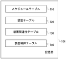
- FIG. 2 is a diagram illustrating an example of a table stored in the storage unit 104 of the server 100.
- FIG. 3 is a diagram illustrating a hardware configuration example of the information processing apparatus.
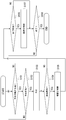
- FIG. 4 is a diagram illustrating an example of an operation flow of the server in the embodiment.
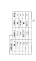
- FIG. 5 is a diagram illustrating an example of a schedule table.
- FIG. 6 is a diagram illustrating an example of a reservation status screen displayed on the display unit of the reservation terminal.
- FIG. 7 is a diagram illustrating an example of a reservation reception screen displayed on the display unit of the reservation terminal.
- FIG. 8 is a diagram illustrating an example of a device association table.
- FIG. 9 is a diagram illustrating an example of a device table.
- FIG. 10 is a diagram illustrating an example of a device control table.
- FIG. 1 is a diagram illustrating a configuration example of a system according to the present embodiment.
- the system 10 of this embodiment includes a server 100, a reservation terminal 200, a control terminal 300, and a work terminal 400.
- the server 100, the reservation terminal 200, the control terminal 300, and the work terminal 400 are connected to each other via a network.
- An air conditioner 320, a microwave oven 330, and a motor 340 are connected to the control terminal 300.
- An electron microscope apparatus 420 is connected to the work terminal 400.
- the air conditioner 320, the microwave oven 330, and the motor 340 which are devices that cause disturbance, are controlled. Devices that cause disturbance to be controlled are not limited to those listed here.
- an apparatus for improving accuracy is not limited to the electron microscope apparatus 420.
- the apparatus for improving accuracy include an apparatus using an accelerated electron beam, a proton beam, and a particle beam, that is, a transmission electron microscope (hereinafter referred to as TEM), a scanning electron microscope (scanning electron microscope).
- SEM scanning electron microscope
- the TEM, SEM, and particle beam therapy system can be devices that cause disturbances in comparison with other devices that improve accuracy.
- the system 10 may include a plurality of devices that improve accuracy. Although the number of control terminals 300 is one here, the system 10 may include a plurality of control terminals 300 that control devices that cause disturbance. Moreover, you may comprise so that the function which controls an apparatus similarly to the control terminal 300 may be implemented on the other work terminal 400 which connected the other electron microscope apparatus 420 grade
- the server 100 includes a processing unit 102, a storage unit 104, a communication unit 106, and a clock unit 108.
- the processing unit 102 instructs control of a device that becomes a disturbance factor based on a use reservation schedule of the electron microscope apparatus 420 and the like.
- the storage unit 104 stores data, tables, programs, and the like used by the server 100.
- the communication unit 106 performs transmission / reception (communication) of data and signals with other devices and the like via a network.
- the clock unit 108 measures time.
- FIG. 2 is a diagram illustrating an example of a table stored in the storage unit 104 of the server 100.
- the storage unit 104 stores a schedule table T10, a device table T20, a device relevance table T30, and a device control table T40. The contents of each table will be described later.
- the reservation terminal 200 includes a processing unit 202, a storage unit 204, a communication unit 206, a display unit 208, and an input unit 210.
- the processing unit 202 performs reservation reception processing for use of the electron microscope apparatus 420 and the like.
- the storage unit 204 stores data, tables, programs, and the like used by the reservation terminal 200.
- the communication unit 206 performs transmission / reception (communication) of data and signals with other devices and the like via a network.
- the display unit 208 displays a reservation status screen and a reservation reception screen for the electron microscope apparatus 420 and the like for the user.
- the input unit 210 accepts a reservation for use of the electron microscope apparatus 420 and the like from the user.
- the control terminal 300 includes a processing unit 302, a storage unit 304, a communication unit 306, and a control unit 308.
- the processing unit 302 receives an instruction from the server 100 and controls the operation of the device that causes a disturbance.
- the storage unit 304 stores data, tables, programs, and the like used by the control terminal 300.
- the communication unit 306 performs transmission / reception (communication) of data and signals with other devices and the like via a network.
- the control unit 308 controls the operation of the connected device based on an instruction from the processing unit 302.
- the control unit 308 acquires the operating state of the connected device.
- An air conditioner 320, a microwave oven 330, and a motor 340 are connected to the control unit 308.
- the work terminal 400 includes a processing unit 402, a storage unit 404, a communication unit 406, a control unit 408, a display unit 410, and an input unit 412.
- the processing unit 402 instructs the control unit 408 to control the operation of the electron microscope apparatus 420.
- the storage unit 404 stores data, tables, programs, etc. used in the work terminal 400.
- the communication unit 406 performs transmission / reception (communication) of data and signals with other devices and the like via a network.
- the control unit 408 controls the operation of the connected device based on an instruction from the processing unit 402.
- the display unit 410 is an output unit that displays the results of the electron microscope apparatus 420.
- the input unit 412 is an input unit for operating the electron microscope apparatus 420.
- the server 100, the reservation terminal 200, the control terminal 300, and the work terminal 400 are a PC (Personal Computer), a smartphone, a mobile phone, a tablet terminal, a car navigation device, a PDA (Personal Digital Assistant), and a workstation (WS, Work Station).
- PC Personal Computer
- smartphone a mobile phone
- tablet terminal a car navigation device
- PDA Personal Digital Assistant
- workstation WS, Work Station
- This can be realized using a dedicated or general-purpose computer such as the above, or an electronic device equipped with a computer.
- FIG. 3 is a diagram illustrating a hardware configuration example of the information processing apparatus.
- the information processing apparatus shown in FIG. 3 has a general computer configuration.
- the server 100, the reservation terminal 200, the control terminal 300, and the work terminal 400 are realized by a computer 90 as shown in FIG. 3 includes a processor 91, a memory 92, a storage unit 93, an input unit 94, an output unit 95, and a communication control unit 96.
- the memory 92 is directly connected to the processor 91, and other than the memory 92 is connected to each other by a bus.
- the storage unit 93 is a computer-readable recording medium.
- the hardware configuration of the computer is not limited to the example shown in FIG. 3, and omissions, replacements, and additions of components may be performed as appropriate.
- the processor 91 loads a program and various data and various tables stored in the recording medium into the work area of the memory 92 and executes the program. Functions that meet the purpose can be realized.
- the processor 91 is, for example, a CPU (Central Processing Unit) or a DSP (Digital Signal Processor).
- CPU Central Processing Unit
- DSP Digital Signal Processor
- the memory 92 includes, for example, a RAM (Random Access Memory) and a ROM (Read Only Memory).
- the memory 92 is also called a main storage device.
- the storage unit 93 is, for example, an EPROM (Erasable Programmable ROM) or a hard disk drive (HDD, Hard Disk Drive).
- the storage unit 93 can include a removable medium, that is, a portable recording medium.
- the removable medium is, for example, a USB (Universal Serial Bus) memory or a disc recording medium such as a CD (Compact Disc) or a DVD (Digital Versatile Disc).
- the storage unit 93 is also called a secondary storage device.
- the storage unit 93 stores various programs, various data, and various tables in a recording medium in a readable and writable manner.
- the storage unit 93 stores an operating system (Operating System: OS), various programs, various tables, and the like.
- Information stored in the storage unit 93 may be stored in the memory 92.
- information stored in the memory 92 may be stored in the storage unit 93.
- the operating system is software that mediates between software and hardware, manages memory space, manages files, manages processes and tasks, and so on.
- the operating system includes a communication interface.
- the communication interface is a program for exchanging data with other external devices connected via the communication control unit 96. Examples of the external device include another computer and an external storage device.
- the input unit 94 includes a keyboard, a pointing device, a wireless remote controller, a touch panel, and the like.
- the input unit 94 may include a video / image input device such as a camera, and an audio input device such as a microphone.
- the output unit 95 includes a display device such as an LCD (Liquid Crystal Display), an EL (Electroluminescence) panel, a CRT (Cathode Ray Tube) display, a PDP (Plasma Display Panel), and an output device such as a printer.
- the output unit 95 can include an audio output device such as a speaker.
- the communication control unit 96 is connected to another device, and controls communication between the computer 90 and the other device.
- the communication control unit 96 is, for example, a LAN (Local Area Network) interface board, a wireless communication circuit for wireless communication, or a communication circuit for wired communication.
- the LAN interface board and the wireless communication circuit are connected to a network such as the Internet.
- the computer that realizes the server 100, the reservation terminal 200, the control terminal 300, and the work terminal 400 loads the program stored in the auxiliary storage device into the main storage device and executes the program, so that the function as each functional unit Is realized.
- each storage unit of the server 100, the reservation terminal 200, the control terminal 300, and the work terminal 400 is provided in a storage area of the main storage device or the auxiliary storage device.
- FIG. 4 is a diagram illustrating an example of an operation flow of the server in the present embodiment.
- a reservation terminal 200, a control terminal 300, and a work terminal 400 are connected to the server 100 through a network so that they can communicate with each other.
- a user who intends to use the electron microscope apparatus 420 uses the reservation terminal 200 to make a use reservation for the electron microscope apparatus 420.
- the user operates the electron microscope apparatus 420 via the work terminal 400 when the reservation date and time (start date and time) of the electron microscope apparatus 420 comes.
- start date and time start date and time
- an operation of an apparatus that hinders accuracy improvement in use of the electron microscope apparatus 420 is controlled.
- the start instruction is given, for example, by the user starting a predetermined application for reservation on the reservation terminal 200.
- the reservation terminal 200 uses the application to request the server 100 for information on the schedule of the SEM that the user intends to make a reservation.
- the processing unit 102 of the server 100 extracts the schedule table T10 stored in the storage unit 104.
- the processing unit 102 extracts the reservation status of each device including the SEM that the user intends to reserve from the schedule table T10.
- FIG. 5 is a diagram showing an example of a schedule table.
- the schedule table T10 stores a reservation for use of the electron microscope apparatus 420 and the like.
- a device ID for identifying the electron microscope device 420 or the like to be used As a reservation status, a device ID for identifying the electron microscope device 420 or the like to be used, a user ID for identifying a user to be reserved, a start date / time for use, an end date / time for use, and a measurement mode for use are associated.
- the measurement mode includes a precision measurement mode and a normal measurement mode. For example, it is assumed that a reservation for use of another apparatus cannot be made in a time slot reserved for use in the precision measurement mode in a certain apparatus. . This is because the operation of another device may affect the measurement performed by the device in the precision measurement mode.
- the processing unit 102 transmits the extracted reservation status to the reservation terminal 200 via the communication unit 106.
- the processing unit 102 of the reservation terminal 200 receives the reservation status of the electron microscope apparatus 420 and the like via the communication unit 206 and stores it in the storage unit 204.
- the processing unit 102 displays the received reservation status on the display unit 208.
- FIG. 6 is a diagram showing an example of a reservation status screen displayed on the display unit of the reservation terminal.
- “normal measurement” by the user “CCC” from 8:00 to 10:00 on October 1 with respect to the SEM, and the user “from 10:00 to 11:00 on October 1 with respect to the TEM.
- “precision measurement” by “AAA” and “normal measurement” by the user “BBB” are reserved from 12:00 to 14:00 on October 1.
- a user who intends to use the electron microscope apparatus 420 can check the reservation status screen displayed on the display unit 208 and consider the apparatus and time zone (start date / time, end date / time) on which he / she makes a use reservation. it can.
- the processing unit 202 of the reservation terminal 200 displays a reservation reception screen on the display unit 208.
- the reservation acceptance screen is provided with input fields for a device for which the user intends to make a reservation for use, a time zone, and a measurement mode.
- the user inputs a device ID for identifying a device for which the user intends to make a use reservation, a time zone, a measurement mode, and a user ID for identifying the user through the input unit 210 of the reservation terminal 200.
- FIG. 7 is a diagram showing an example of a reservation reception screen displayed on the display unit of the reservation terminal.
- the reservation acceptance screen in FIG. 7 includes columns for inputting a device ID for identifying a device desired to be used, a user ID, a start date / time, an end date / time, and a measurement mode (normal measurement or precision measurement).
- the reservation reception screen may be displayed together with the reservation status screen.
- the time zone in which the device is used is specified by the start date / time and the end date / time, but the time zone in which the device is used may be specified by the start date / time and the usage period (time).
- the processing unit 202 of the reservation terminal 200 stores the reservation information in the storage unit 204.
- the processing unit 202 transmits the input reservation information to the server 100 via the communication unit 206.
- the processing unit 102 of the server 100 determines whether reservation information has been received from the reservation terminal 200. If reservation information has not been received (S101; NO), the process proceeds to S104. When the reservation information is received (S101; YES), the processing unit 102 stores the received reservation information in the storage unit 104. Thereafter, the process proceeds to S102.
- the processing unit 102 determines whether or not a reservation based on the received reservation information is possible.
- the processing unit 102 compares the apparatus and time zone (from the start date and time to the end date and time) of the received reservation information with the reservation information in the schedule table T10 stored in the storage unit 104. When the reservation information in the schedule table T10 and the received reservation information overlap in the same device, the processing unit 102 determines that reservation is not possible. Further, when the measurement mode of the received reservation information is the precise measurement mode and the reservation information of another device is included in the schedule table T10 in the time zone included in the received reservation information, the processing unit 102 In consideration of the influence level, it is determined that the reservation is not possible when the influence degree is medium or large.
- the processing unit 102 determines whether there is no influence, for example, when there is no overlapping reservation, when the measurement mode is the normal measurement mode, or when the influence degree between apparatuses is considered. If is small, it may be determined that reservation is possible.
- the processing unit 102 transmits information indicating that reservation is not possible to the reservation terminal 200 via the communication unit 106.
- the processing unit 202 of the reservation terminal 200 receives information indicating that reservation is not possible via the communication unit 206, the processing unit 202 displays on the display unit 208 that reservation is not possible. The user who confirms the display recognizes that the reservation is not possible, and can input a new reservation on the reservation reception screen.
- the processing in the server 100 returns to S101.
- the processing unit 102 transmits information indicating that reservation is possible to the reservation terminal 200 via the communication unit 106.
- the processing unit 202 of the reservation terminal 200 receives information indicating that reservation is possible via the communication unit 206
- the processing unit 202 displays on the display unit 208 that reservation is possible. The user who confirms the display recognizes that the reservation has been made.
- the processing in the server 100 proceeds to S103.
- the processing unit 102 registers the received reservation information in the schedule table T10.
- the processing unit 102 stores the schedule table T10 in which the received reservation information is registered in the storage unit 104.
- the processing unit 102 acquires information on the current date and time from the clock unit 108.
- the processing unit 102 determines whether or not the current date and time match the start date and time of the reservation information included in the schedule table T10 stored in the storage unit 104. If they match (S104; YES), the process proceeds to S105. If they do not match (S104; NO), the process proceeds to S106.
- the processing unit 102 of the server 100 extracts the device ID of the reservation information that has reached the start date and time in S104.
- a device such as an electron microscope device
- the processing unit 102 extracts a record relating to the extracted device ID from the device relevance table T30 stored in the storage unit 104.
- the device relevance table T30 is a table showing correspondence between devices to be used and disturbance factors when the devices are used.
- the device relevance table T30 includes a device (target device) that can cause disturbance, an event (target event) that can cause disturbance, and the influence of the disturbance on the device when using the device corresponding to the device ID. It is a table that stores degrees in association with device IDs.
- FIG. 8 is a diagram showing an example of the device relevance table.
- the device association table T30 in FIG. 8 includes a device ID corresponding to a device to be used, a target device ID corresponding to a device that causes a disturbance to the device, and a target event (vibration, which can cause a disturbance).
- the influence degree of the disturbance on the device are stored in association with each other.
- the degree of influence is represented by “high”, “medium”, and “small”, but may be represented by a numerical value that increases as the degree of influence increases.
- Devices that cause disturbance may include other electron microscope devices, particle beam therapy devices, and the like.
- the processing unit 102 extracts a record related to the target device ID included in the record extracted from the device relevance table T30 from the device table T20 stored in the storage unit 104.
- the device table T20 is a table showing correspondence between devices, model numbers, installation positions, control methods, and the like.
- FIG. 9 is a diagram showing an example of the device table.
- the device table T20 of FIG. 9 controls the device ID corresponding to the device, the manufacturer that manufactured the device, the model number of the device, the installation position of the device, the control terminal that controls the device, and the device. And a control object representing a program, a standard, and the like, and an address / port indicating an access route from the control terminal to the device are stored in association with each other.
- “address / port” describes an address on the network.
- the “address / port” describes the connection port.
- the connection between the control terminal 300 and the apparatus can be performed by communication using USB, serial connection, LAN, infrared rays, or the like.
- the format of “address / port” may be a URI (Uniform Resource Identifier) format for uniquely identifying an interface that controls the controlled device resource. This makes it possible to use the control service particularly when the controlled device publishes a control API (Application Program Interface) using Web technology.
- control objects that control air conditioners such as air conditioners include H-LINK / H-LINK2 and DIII-NET.
- the control object can control temperature, air volume, and the like.
- control objects that control lighting, power, air conditioning, and the like in buildings include LONWORKS, BAC-net, X10, KNX (Konnex), JEM-A, and ECHONET-LITE.
- control objects that control home appliances include UPnP, DLNA (registered trademark), IGRS, and the like.
- the control object is appropriately selected according to the device to be controlled. In addition, it is possible to control a device that may cause a disturbance by other existing techniques.
- the processing unit 102 extracts, from the device control table T40 stored in the storage unit 104, a record that matches the target device ID, the target event, and the influence included in the record extracted from the device relevance table T30.
- the device control table T40 is a table in which control contents corresponding to the target device, the target event, and the degree of influence are stored.
- FIG. 10 is a diagram showing an example of the device control table.
- the device control table T40 of FIG. 10 includes a target device ID of a device to be controlled, a target event that can cause a disturbance, a degree of influence of the disturbance, a command to be controlled, an operation condition of the command,
- the parameter for the command is stored in association with it. For example, if the target device ID is “air conditioner”, the target event is “temperature”, and the influence degree is “high”, and the operation mode of the air conditioner is “heating”, the control command “temperature” Then, the parameter is set to “ ⁇ 2 ° C.”. Thereby, the temperature of the air conditioner is lowered by 2 ° C.
- the processing unit 102 transmits, via the communication unit 106, an instruction to control a device that causes a disturbance to the control terminal 300 included in the record extracted from the device table T20.
- the instruction includes a device ID of a device to be controlled, a control object, an address / port, a command to be controlled, a command operation condition, a parameter for the command, and the like.
- the contents included in the instruction are information extracted from the device table T20, the device relevance table T30, and the device control table T40.
- the processing unit 302 of the control terminal 300 receives an instruction to control a device that causes a disturbance via the communication unit 306.
- the processing unit 302 stores the received instruction in the storage unit 304.
- the processing unit 302 instructs the control unit 308 to acquire the current state of the device included in the received instruction.
- the control unit 308 acquires the current state of the device included in the instruction.
- the control unit 308 acquires the current state using a control object corresponding to each device.
- the control unit 308 notifies the processing unit 302 of the acquired current state of each device.
- the processing unit 302 stores the notified current state of each device (the state before the start date and time) in the storage unit 304.
- the processing unit 302 instructs the control unit 308 to execute a command for each device included in the received instruction.
- the control unit 308 executes each device with a control command and a parameter for the command using a control object corresponding to each device. Each device performs a predetermined operation according to a control command and a parameter.
- the control unit 308 notifies the processing unit 302 of the completion of the instruction.
- the processing unit 302 notifies the server 100 of the completion of the instruction via the communication unit 306.
- the processing unit 102 of the server 100 receives an instruction completion notification from the control terminal 300 via the communication unit 106.
- the processing unit 102 of the server 100 may notify the work terminal 400 of the completion of the instruction via the communication unit 106.
- the processing unit 402 of the work terminal 400 that has received the notification of the completion of the instruction via the communication unit 406 informs the display unit 410 that the instruction has been completed (that is, completion of the predetermined control for the device that causes the disturbance). indicate.
- a user who has reserved use of the apparatus can confirm the display on the display unit 410 and start using the apparatus (the electron microscope apparatus 420).
- Predetermined control over the device that causes the disturbance reduces the disturbance. Therefore, when the user waits for the notification of completion and starts using the apparatus (the electron microscope apparatus 420), the measurement accuracy can be improved. Further, as long as the processing unit 402 does not receive the completion notification, the control unit 408 may perform control so that the electron microscope apparatus 420 cannot be used.
- the user who made a use reservation of the electron microscope apparatus 420 can use the electron microscope apparatus 420 from the start date and time of the use reservation.
- the use of the electron microscope apparatus 420 is performed via the work terminal 400.
- the user can operate the electron microscope apparatus 420 with the input unit 412 of the work terminal 400 and check the state of the electron microscope apparatus 420 with the display unit 410 or the like.
- the processing unit 102 acquires the current date and time information from the clock unit 108.
- the processing unit 102 determines whether or not the current date and time match the end date and time of the reservation information included in the schedule table T10 stored in the storage unit 104. If they match (S106; YES), the process proceeds to S107. If they do not match (S106; NO), the process proceeds to S108.
- the processing unit 102 of the server 100 extracts the device ID of the reservation information that has reached the end date and time in S106.
- a device such as an electron microscope device
- the processing unit 102 starts the state of the device that causes the disturbance to the control terminal 300 that has transmitted an instruction to control the device that causes the disturbance in S105.
- An instruction to return to the state before the date and time is transmitted via the communication unit 106.
- the processing unit 302 of the control terminal 300 receives an instruction from the server 100 via the communication unit 306, the processing unit 302 acquires a state before the start date and time of each device that causes a disturbance stored in the storage unit 304.
- the processing unit 302 instructs the control unit 308 to return each device that causes a disturbance to the state before the start date and time.
- the control unit 308 instructs each device to be in the same state as the state before the start date and time using the control object. Each device returns the state to the state before the start date and time based on the instruction.
- the control unit 308 notifies the processing unit 302 of the completion of the instruction.
- the processing unit 302 When receiving the instruction completion notification from the control unit 308, the processing unit 302 notifies the server 100 of the completion of the instruction via the communication unit 306.
- the processing unit 102 of the server 100 receives an instruction completion notification from the control terminal 300 via the communication unit 106.
- the processing unit 102 of the server 100 may notify the work terminal 400 of the completion of the instruction via the communication unit 106.
- the processing unit 402 of the work terminal 400 that has received the notification of the completion of the instruction via the communication unit 406 indicates the completion of the instruction (that is, the completion of the process of returning to the state before the start date and time for the device that causes the disturbance). Is displayed on the display unit 410.
- the user who has used the apparatus can confirm the display on the display unit 410 and confirm that the state of the device that causes the disturbance has returned to the state before the start date and time.
- the server 100 may not perform the operation of S105 until a work start signal is received from the work terminal 400 that controls the reserved apparatus. This is because it is not necessary to remove the cause of the disturbance when the device is reserved but not used.
- the server 100 may not perform the operation of S107 until a work end signal is received from the work terminal 400 that controls the reserved apparatus. This is because, if the device that causes the disturbance is returned to the state before the start date and time before the work is finished, it becomes a factor of disturbance (decrease in measurement accuracy) in the work (for example, measurement with the electron microscope device 420). Further, the server 100 may perform the operation of S107 by receiving a work end signal from the work terminal 400 that controls the reserved device even before the end date / time is reached. This is because once the work is completed, there is no problem even if the device that causes the disturbance is returned to the state before the start date and time.
- a specific use reservation may be canceled.
- the reservation terminal 200 notifies the server 100 via the communication unit 206 that the specific use reservation has been canceled.
- the processing unit 102 of the server 100 receives a notification of cancellation of a specific use reservation via the communication unit 106, the processing unit 102 deletes the use reservation from the schedule table T10 stored in the storage unit 104. As a result, the use reservation can be canceled. Further, it may be possible to cancel after the start date and time but before the end date and time, that is, within the reserved time zone.
- the date and time when the device that causes the disturbance is controlled may be the date and time when the time offset is set with respect to the start date and time.
- the control (operations in S104 and S105) for the device that causes the disturbance may be performed on the date and time shifted from the start date and time by the time offset.
- the value of the time offset may be positive or negative. The same applies to the operation related to the end date and time (the operations of S106 and S107).
- Any two or more devices of the server 100, the reservation terminal 200, the control terminal 300, and the work terminal 400 may operate integrally.
- the server 100 and the reservation terminal 200 may operate integrally.
- the system 10 controls a device that causes a disturbance such as measurement of the electron microscope apparatus 420 and the like during a time slot reserved for use of the electron microscope apparatus 420 and the like, thereby removing the cause of the disturbance.
- a device that causes a disturbance such as measurement of the electron microscope apparatus 420 and the like during a time slot reserved for use of the electron microscope apparatus 420 and the like, thereby removing the cause of the disturbance.
- Computer-readable recording medium A program for causing a computer or other machine or device (hereinafter, a computer or the like) to realize any of the above functions can be recorded on a recording medium that can be read by the computer or the like.
- the function can be provided by causing a computer or the like to read and execute the program of the recording medium.
- a computer-readable recording medium is a recording medium that stores information such as data and programs by electrical, magnetic, optical, mechanical, or chemical action and can be read from a computer or the like.
- elements constituting a computer such as a CPU and a memory may be provided to cause the CPU to execute a program.
- recording media that can be removed from a computer or the like, there are, for example, a flexible disk, a magneto-optical disk, a CD-ROM, a CD-R / W, a DVD, a DAT, an 8 mm tape, and a memory card.
- a hard disk a ROM, etc. as a recording medium fixed to a computer or the like.
Landscapes
- Engineering & Computer Science (AREA)
- Business, Economics & Management (AREA)
- General Business, Economics & Management (AREA)
- Theoretical Computer Science (AREA)
- Strategic Management (AREA)
- General Physics & Mathematics (AREA)
- Physics & Mathematics (AREA)
- Tourism & Hospitality (AREA)
- Economics (AREA)
- Entrepreneurship & Innovation (AREA)
- Human Resources & Organizations (AREA)
- Health & Medical Sciences (AREA)
- Quality & Reliability (AREA)
- Development Economics (AREA)
- Operations Research (AREA)
- Marketing (AREA)
- Primary Health Care (AREA)
- Biomedical Technology (AREA)
- Epidemiology (AREA)
- Public Health (AREA)
- Medical Informatics (AREA)
- General Health & Medical Sciences (AREA)
- Educational Administration (AREA)
- Game Theory and Decision Science (AREA)
- Computer Networks & Wireless Communication (AREA)
- General Engineering & Computer Science (AREA)
- Air Conditioning Control Device (AREA)
- Management, Administration, Business Operations System, And Electronic Commerce (AREA)
- Selective Calling Equipment (AREA)
- Telephonic Communication Services (AREA)
- Information Transfer Between Computers (AREA)
- Medical Treatment And Welfare Office Work (AREA)
Abstract
外乱の要因となる機器を制御して、所定の装置の使用時における精度向上を図る。第1装置を使用するための予約情報であって、前記第1装置の使用の開始日時及び終了日時に相当する情報を含む前記予約情報を格納する記憶部と、前記記憶部に格納される前記予約情報に基づく前記開始日時に達した場合、第2装置を所定の状態にするための第1指示を、前記第2装置を制御する制御端末に送信し、前記記憶部に格納される前記予約情報に基づく前記終了日時に達した場合、前記第2装置を前記開始日時前の状態にするための第2指示を、前記制御端末に送信する処理部とを備えるサーバとする。
Description
本発明は、サーバ、制御システム、制御方法、及び、制御プログラムに関する。
電子顕微鏡装置や粒子線治療装置など、荷電粒子の照射と挙動を用いた計測・医用・産業装置がある。これらの装置において、荷電粒子の挙動が外乱により変動すると、計測値のばらつき、強度分布から構成した画像のボケやブレ、治療効果の低下などの可能性が高まる。ここで、外乱とは、振動、音、風等による装置の揺らぎ、電磁波、電界、磁界の変化、電源電圧・電流の変動、放射線量の変化などである。外乱の要因には、エアコンからの風、電子レンジ/無線機等からの電磁波、モータ等を有する装置からの振動、電力使用量の大きい装置の動作などがある。
電子顕微鏡装置や粒子線治療装置などにおいて、計測値や強度分布画像取得、粒子放射部位の位置収束などの精度向上のためには、粒子の挙動を乱す周囲環境の制御(外乱要因の除去)が求められる。しかし電子顕微鏡装置等の装置の精度向上のために、外乱の要因となる機器を制御することは、非常に難しい。
本発明は、外乱の要因となる機器を制御して、所定の装置の使用時における精度向上を図ることを目的とする。
上記課題を解決するために、以下の手段を採用する。
即ち、第1の態様は、
第1装置を使用するための予約情報であって、前記第1装置の使用の開始日時及び終了日時に相当する情報を含む前記予約情報を格納する記憶部と、
前記記憶部に格納される前記予約情報に基づく前記開始日時に達した場合、第2装置を所定の状態にするための第1指示を、前記第2装置を制御する制御端末に送信し、
前記記憶部に格納される前記予約情報に基づく前記終了日時に達した場合、前記第2装置を前記開始日時前の状態にするための第2指示を、前記制御端末に送信する処理部と、を備えるサーバとする。
即ち、第1の態様は、
第1装置を使用するための予約情報であって、前記第1装置の使用の開始日時及び終了日時に相当する情報を含む前記予約情報を格納する記憶部と、
前記記憶部に格納される前記予約情報に基づく前記開始日時に達した場合、第2装置を所定の状態にするための第1指示を、前記第2装置を制御する制御端末に送信し、
前記記憶部に格納される前記予約情報に基づく前記終了日時に達した場合、前記第2装置を前記開始日時前の状態にするための第2指示を、前記制御端末に送信する処理部と、を備えるサーバとする。
開示の態様は、プログラムが情報処理装置によって実行されることによって実現されてもよい。即ち、開示の構成は、上記した態様における各手段が実行する処理を、情報処理装置に対して実行させるためのプログラム、或いは当該プログラムを記録したコンピュータ読み取り可能な記録媒体として特定することができる。また、開示の構成は、上記した各手段が実行する処理を情報処理装置が実行する方法をもって特定されてもよい。開示の構成は、上記した各手段が実行する処理を行う情報処理装置を含むシステムとして特定されてもよい。
プログラムを記述するステップは、記載された順序に沿って時系列的に行われる処理はもちろん、必ずしも時系列的に処理されなくても、並列的または個別に実行される処理を含む。プログラムを記述するステップの一部が省略されてもよい。
本発明によれば、外乱の要因となる機器を制御して、所定の装置の使用時における精度向上を図ることができる。
以下、図面を参照して実施形態について説明する。実施形態の構成は例示であり、発明の構成は、開示の実施形態の具体的構成に限定されない。発明の実施にあたって、実施形態に応じた具体的構成が適宜採用されてもよい。
図1は、本実施形態のシステムの構成例を示す図である。本実施形態のシステム10は、サーバ100、予約端末200、制御端末300、作業端末400を含む。サーバ100、予約端末200、制御端末300、作業端末400は、互いに、ネットワークを介して接続されている。制御端末300には、エアコン320、電子レンジ330、モータ340が接続されている。作業端末400には、電子顕微鏡装置420が接続されている。ここでは、電子顕微鏡装置420の使用する際の精度向上のために、外乱の要因となる機器であるエアコン320、電子レンジ330、モータ340を制御する。制御される外乱の要因となる機器は、ここに挙げたものに限定されるものではない。また、精度向上を図る装置は、電子顕微鏡装置420に限定されるものではない。精度向上を図る装置には、例えば、加速した電子線や陽子線および粒子線を用いる装置、すなわち、透過型電子顕微鏡(Transmission Electron Microscope、以下、TEMと略す)、走査型電子顕微鏡(Scanning Electron Microscope、以下、SEMと略す)、放射線や粒子線治療装置、などが代表として挙げられる。TEM、SEM、粒子線治療装置は、他の精度向上を図る装置に対して、装置自体が外乱の要因となる機器になり得る。システム10は、精度向上を図る装置を複数含んでもよい。ここでは、制御端末300は、1つとしているが、システム10は、外乱の要因となる機器を制御する制御端末300を複数含んでもよい。また、外乱の要因となり得る他の電子顕微鏡装置420等を接続した他の作業端末400上で、制御端末300と同様に機器を制御する機能を実施するように構成してもよい。
サーバ100は、処理部102、記憶部104、通信部106、時計部108を含む。
処理部102は、電子顕微鏡装置420等の使用予約スケジュールに基づいて、外乱要因となる機器の制御を指示する。記憶部104は、サーバ100で使用されるデータ、テーブル、プログラム等を格納する。通信部106は、ネットワークを介して、他の装置等と、データ、信号の送受信(通信)を行う。時計部108は、時刻を計時する。
処理部102は、電子顕微鏡装置420等の使用予約スケジュールに基づいて、外乱要因となる機器の制御を指示する。記憶部104は、サーバ100で使用されるデータ、テーブル、プログラム等を格納する。通信部106は、ネットワークを介して、他の装置等と、データ、信号の送受信(通信)を行う。時計部108は、時刻を計時する。
図2は、サーバ100の記憶部104に格納されるテーブルの例を示す図である。記憶部104は、スケジュールテーブルT10、装置テーブルT20、装置関連性テーブルT30、装置制御テーブルT40を格納する。各テーブルの内容については、後に説明する。
予約端末200は、処理部202、記憶部204、通信部206、表示部208、入力部210を含む。処理部202は、電子顕微鏡装置420等の使用の予約受付処理を行う。記憶部204は、予約端末200で使用されるデータ、テーブル、プログラム等を格納する。通信部206は、ネットワークを介して、他の装置等と、データ、信号の送受信(通信)を行う。表示部208は、電子顕微鏡装置420等の予約状況画面や予約受付画面を利用者に向けて表示する。入力部210は、利用者から電子顕微鏡装置420等の使用の予約を受け付ける。
制御端末300は、処理部302、記憶部304、通信部306、制御部308を含む。処理部302は、サーバ100からの指示を受けて、外乱の要因となる機器の動作を制御する。記憶部304は、制御端末300で使用されるデータ、テーブル、プログラム等を格納する。通信部306は、ネットワークを介して、他の装置等と、データ、信号の送受信(通信)を行う。制御部308は、処理部302からの指示に基づき、接続される機器の動作を制御する。制御部308は、接続される機器の動作状態を取得する。制御部308には、エアコン320、電子レンジ330、モータ340が接続される。
作業端末400は、処理部402、記憶部404、通信部406、制御部408、表示部410、入力部412を含む。処理部402は、電子顕微鏡装置420の動作を制御する指示を制御部408に向けて行う。記憶部404は、作業端末400で使用されるデータ、テーブル、プログラム等を格納する。通信部406は、ネットワークを介して、他の装置等と、データ、信号の送受信(通信)を行う。制御部408は、処理部402からの指示に基づき、接続される装置の動作を制御する。表示部410は、電子顕微鏡装置420における結果等を表示する出力手段である。入力部412は、電子顕微鏡装置420を操作するための入力手段である。
サーバ100、予約端末200、制御端末300、作業端末400は、PC(Personal Computer)、スマートフォン、携帯電話、タブレット型端末、カーナビゲーション装置、PDA(Personal Digital Assistant)、ワークステーション(WS、Work Station)のような専用または汎用のコンピュータ、あるいは、コンピュータを搭載した電子機器を使用して実現可能である。
図3は、情報処理装置のハードウェア構成例を示す図である。図3に示す情報処理装置は、一般的なコンピュータの構成を有している。サーバ100、予約端末200、制御端末300、作業端末400は、図3に示すようなコンピュータ90によって実現される。図3のコンピュータ90は、プロセッサ91、メモリ92、記憶部93、入力部94、出力部95、通信制御部96を有する。メモリ92はプロセッサ91と直接接続し、メモリ92以外は互いにバスによって接続される。記憶部93は、コンピュータ読み取り可能な記録媒体である。コンピュータのハードウェア構成は、図3に示される例に限らず、適宜構成要素の省略、置換、追加が行われてもよい。
コンピュータ90は、プロセッサ91が記録媒体に記憶されたプログラムおよび各種データや各種テーブルをメモリ92の作業領域にロードして実行し、プログラムの実行を通じて各構成部等が制御されることによって、所定の目的に合致した機能を実現することができる。
プロセッサ91は、例えば、CPU(Central Processing Unit)やDSP(Digital Signal Processor)である。
メモリ92は、例えば、RAM(Random Access Memory)やROM(Read Only Memory)を含む。メモリ92は、主記憶装置とも呼ばれる。
記憶部93は、例えば、EPROM(Erasable Programmable ROM)、ハードディスクドライブ(HDD、Hard Disk Drive)である。また、記憶部93は、リムーバブルメディア、即ち可搬記録媒体を含むことができる。リムーバブルメディアは、例えば、USB(Universal Serial Bus)メモリ、あるいは、CD(Compact Disc)やDVD(Digital Versatile Disc)のようなディスク記録媒体である。記憶部93は、二次記憶装置とも呼ばれる。
記憶部93は、各種のプログラム、各種のデータ及び各種のテーブルを読み書き自在に記録媒体に格納する。記憶部93には、オペレーティングシステム(Operating System :OS)、各種プログラム、各種テーブル等が格納される。記憶部93に格納される情報は、メモリ92に格納されてもよい。また、メモリ92に格納される情報は、記憶部93に格納されてもよい。
オペレーティングシステムは、ソフトウェアとハードウェアとの仲介、メモリ空間の管理、ファイル管理、プロセスやタスクの管理等を行うソフトウェアである。オペレーティングシステムは、通信インタフェースを含む。通信インタフェースは、通信制御部96を介して接続される他の外部装置等とデータのやり取りを行うプログラムである。外部装置等には、例えば、他のコンピュータ、外部記憶装置等が含まれる。
入力部94は、キーボード、ポインティングデバイス、ワイヤレスリモコン、タッチパネル等を含む。また、入力部94は、カメラのような映像や画像の入力装置や、マイクロフォンのような音声の入力装置を含むことができる。
出力部95は、LCD(Liquid Crystal Display)、EL(Electroluminescence)パネル、CRT(Cathode Ray Tube)ディスプレイ、PDP(Plasma Display Panel)等の表示装置、プリンタ等の出力装置を含む。また、出力部95は、スピーカのような音声の出力装置を含むことができる。
通信制御部96は、他の装置と接続し、コンピュータ90と他の装置との間の通信を制御する。通信制御部96は、例えば、LAN(Local Area Network)インタフェースボード、無線通信のための無線通信回路、有線通信のための通信回路である。LANインタフェースボードや無線通信回路は、インターネット等のネットワークに接続される。
サーバ100、予約端末200、制御端末300、作業端末400を実現するコンピュータは、プロセッサが補助記憶装置に記憶されているプログラムを主記憶装置にロードして実行することによって、各機能部としての機能を実現する。一方、サーバ100、予約端末200、制御端末300、作業端末400の各記憶部は、それぞれの、主記憶装置または補助記憶装置の記憶領域に設けられる。
(動作例)
図4は、本実施形態におけるサーバの動作フローの例を示す図である。サーバ100には、予約端末200、制御端末300、作業端末400が、ネットワークを介して、通信可能に、接続されている。
図4は、本実施形態におけるサーバの動作フローの例を示す図である。サーバ100には、予約端末200、制御端末300、作業端末400が、ネットワークを介して、通信可能に、接続されている。
電子顕微鏡装置420を使用しようとする利用者は、予約端末200を用いて、電子顕微鏡装置420の使用予約を行う。当該利用者は、電子顕微鏡装置420の予約日時(開始日時)になったら、作業端末400を介して、電子顕微鏡装置420の操作を行う。このとき、サーバ100から制御端末300への指示により、電子顕微鏡装置420の使用において精度向上の妨害となる機器の動作が制御される。
利用者が予約端末200に対して電子顕微鏡装置420(SEMとする)の使用の予約の開始を指示することを契機として、図4の動作フローが、開始する。開始の指示は、例えば、利用者が予約端末200において予約用の所定のアプリケーションを起動することにより行う。予約端末200は、当該アプリケーションにより、利用者が予約しようとするSEMのスケジュールの情報を、サーバ100に要求する。
S101では、サーバ100の処理部102は、記憶部104に格納されるスケジュールテーブルT10を抽出する。処理部102は、スケジュールテーブルT10から、利用者が予約しようとするSEMを含む各装置の予約状況を抽出する。
図5は、スケジュールテーブルの例を示す図である。スケジュールテーブルT10は、電子顕微鏡装置420等の使用予約を格納する。スケジュールテーブルT10では、予約状況として、使用しようとする電子顕微鏡装置420等を識別する装置ID、予約する利用者を識別するユーザID、使用の開始日時、使用の終了日時、使用する際の測定モードが対応付けられている。ここでは、測定モードには、精密測定モードと通常測定モードとがあり、例えば、ある装置において精密測定モードで使用予約されている時間帯には、他の装置の使用予約を入れられないとする。他の装置の動作が、精密測定モードで行う当該装置での測定に影響を与えるおそれがあるからである。
処理部102は、抽出した予約状況を、通信部106を介して、予約端末200に送信する。予約端末200の処理部102は、通信部206を介して、電子顕微鏡装置420等の予約状況を受信し、記憶部204に格納する。処理部102は、受信した予約状況を、表示部208に表示する。
図6は、予約端末の表示部に表示される予約状況画面の例を示す図である。図6の予約状況画面では、SEMに対して、10月1日8時から10時までユーザ「CCC」による「通常測定」、TEMに対して、10月1日10時から11時までユーザ「AAA」による「精密測定」及び10月1日12時から14時までユーザ「BBB」による「通常測定」が予約されていることが分かる。電子顕微鏡装置420を使用しようとする利用者は、表示部208に表示される予約状況画面を確認して、自身が使用予約をする装置や時間帯(開始日時、終了日時)を検討することができる。
予約端末200の処理部202は、表示部208に予約受付画面を表示する。予約受付画面には、利用者が使用予約をしようとする装置、時間帯、測定モードの入力欄が設けられる。利用者は、予約端末200の入力部210により、利用者が使用予約をしようとする装置を識別する装置ID、時間帯、測定モード、利用者を識別するユーザIDを入力する。
図7は、予約端末の表示部に表示される予約受付画面の例を示す図である。図7の予約受付画面では、使用を希望する装置を識別する装置ID、ユーザID、開始日時、終了日時、測定モード(通常測定、または、精密測定)を入力する欄が設けられる。予約受付画面は、予約状況画面とともに表示されてもよい。ここでは、開始日時と終了日時とで、装置を使用する時間帯が指定されているが、開始日時と使用期間(時間)とで、装置を使用する時間帯が指定されてもよい。
予約端末200の処理部202は、入力部210を介して、予約情報(装置、ユーザID、開始日時、終了日時、測定モード)が入力されると、予約情報を記憶部204に格納する。また、処理部202は、入力された予約情報を、通信部206を介してサーバ100に送信する。
サーバ100の処理部102は、予約端末200から予約情報を受信したか否かを判定する。予約情報を受信していない場合(S101;NO)、処理がS104に進む。予約情報を受信した場合(S101;YES)、処理部102は受信した予約情報を、記憶部104に格納する。その後、処理がS102に進む。
S102では、処理部102は、受信した予約情報による予約が可能であるか否かを判定する。処理部102は、受信した予約情報の装置、時間帯(開始日時から終了日時まで)と、記憶部104に格納されるスケジュールテーブルT10の予約情報とを比較する。処理部102は、スケジュールテーブルT10の予約情報と、受信した予約情報とが同じ装置で重複する場合、予約不可と判定する。また、処理部102は、受信した予約情報の測定モードが精密測定モードであり、かつ、受信した予約情報に含まれる時間帯に他の装置の予約情報がスケジュールテーブルT10に含まれる場合、装置間の影響度を考慮して影響度が中や大のときは予約不可と判定する。また、処理部102は、上記以外の場合、例えば、重複する予約がない場合、測定モードが互いに通常測定モードである場合、あるいは、装置間の影響度を考慮して影響を与えないか影響度が小である場合には予約可能と判定してもよい。
予約不可と判定した場合(S102;NO)、処理部102は、予約不可である旨の情報を、通信部106を介して、予約端末200に送信する。予約端末200の処理部202は、通信部206を介して、予約不可である旨の情報を受信すると、予約不可である旨を表示部208に表示する。表示を確認した利用者は、予約不可であることを認識し、新たな予約を予約受付画面において入力することができる。一方、サーバ100における処理は、S101に戻る。
予約可能と判定した場合(S102;YES)、処理部102は、予約可能である旨の情報を、通信部106を介して、予約端末200に送信する。予約端末200の処理部202は、通信部206を介して、予約可能である旨の情報を受信すると、予約可能である旨を表示部208に表示する。表示を確認した利用者は、予約できたことを認識する。一方、サーバ100における処理は、S103に進む。
S103では、処理部102は、受信した予約情報を、スケジュールテーブルT10に登録する。処理部102は、受信した予約情報を登録したスケジュールテーブルT10を、記憶部104に格納する。
S104では、処理部102は、時計部108から、現在日時の情報を取得する。処理部102は、現在日時が、記憶部104に格納されるスケジュールテーブルT10に含まれる予約情報の開始日時に一致したか否かを判定する。一致した場合(S104;YES)、処理がS105に進む。一致しない場合(S104;NO)、処理がS106に進む。
S105では、サーバ100の処理部102は、S104で開始日時に達した予約情報の装置IDを抽出する。当該装置IDに対応する装置(電子顕微鏡装置など)が、利用者が使用しようとする装置である。処理部102は、記憶部104に格納される装置関連性テーブルT30から、抽出した装置IDに関するレコードを抽出する。装置関連性テーブルT30は、使用する装置と、当該装置の使用の際の外乱の要因との対応付けを示すテーブルである。装置関連性テーブルT30は、装置IDに対応する装置を使用する際に、外乱の要因になり得る機器(対象装置)と、外乱の要因になり得る事象(対象事象)と、外乱の装置に対する影響度とを、装置IDに対応付けて格納するテーブルである。
図8は、装置関連性テーブルの例を示す図である。図8の装置関連性テーブルT30は、使用する装置に対応する装置IDと、当該装置に対して外乱の要因となる機器に対応する対象装置IDと、外乱の要因になり得る対象事象(振動、電界など)と、外乱の装置に対する影響度とを、対応付けて格納する。影響度は、ここでは、「高」「中」「小」で表されているが、影響度が高くなるほど大きくなる数値で表されてもよい。外乱の要因となる機器には、他の電子顕微鏡装置や粒子線治療装置などが含まれてもよい。
処理部102は、記憶部104に格納される装置テーブルT20から、装置関連性テーブルT30から抽出したレコードに含まれる対象装置IDに関するレコードを抽出する。装置テーブルT20は、装置と、型番、設置位置、制御方法等との対応付けを示すテーブルである。
図9は、装置テーブルの例を示す図である。図9の装置テーブルT20は、装置に対応する装置IDと、当該装置を製造したメーカと、当該装置の型番と、当該装置の設置位置と、当該装置を制御する制御端末と、当該装置を制御するためのプログラムや規格等を表す制御オブジェクトと、制御端末から当該装置へのアクセスルート等を示すアドレス/ポートとを対応付けて格納する。制御端末が装置にネットワークを介して接続されている場合には、「アドレス/ポート」には、ネットワーク上のアドレスが記載される。制御端末が装置に直接接続されている場合には、「アドレス/ポート」には、接続ポートが記載される。制御端末300と装置との接続は、USB、シリアル接続、LAN、赤外線等を用いた通信で行うことができる。なお、この「アドレス/ポート」の書式は、被制御装置資源の制御を行うインタフェースを一意に識別するためのURI(Uniform Resource Identifier)形式としてもよい。これにより、特に、被制御装置がWeb技術を用いて制御用のAPI(Application Program Interface)を公開している場合に、その制御サービスを利用することもできる。
エアコン等の空調機器を制御する制御オブジェクトには、例えば、H-LINK/H-LINK2やDIII-NET等がある。当該制御オブジェクトにより、温度や風量などを制御することができる。ビルなどにおいて照明、電力、空調等を制御する制御オブジェクトには、例えば、LONWORKS、BAC-net、X10、KNX(Konnex)、JEM-A、ECHONET-LITE等がある。家電機器などを制御する制御オブジェクトには、例えば、UPnP、DLNA(登録商標)、IGRS等がある。制御オブジェクトは、制御される機器に応じて適切に選択される。また、その他の既存の技術により、外乱の要因となり得る機器の制御をすることができる。
また、処理部102は、記憶部104に格納される装置制御テーブルT40から、装置関連性テーブルT30から抽出したレコードに含まれる対象装置ID、対象事象、影響度が一致するレコードを抽出する。装置制御テーブルT40は、対象装置、対象事象、影響度に応じた制御内容が格納されるテーブルである。
図10は、装置制御テーブルの例を示す図である。図10の装置制御テーブルT40は、制御の対象となる装置の対象装置IDと、外乱の要因になり得る対象事象と、外乱の影響度と、制御するコマンドと、当該コマンドの動作条件と、当該コマンドに対するパラメータとを対応付けて格納する。例えば、対象装置IDが「エアコン」であって、対象事象が「温度」であって、影響度が「高」である場合、エアコンの動作モードが「暖房」であれば、制御コマンド「温度」で、パラメータを「-2℃」とする。これにより、エアコンの温度が2℃下げられる。
処理部102は、装置テーブルT20から抽出されたレコードに含まれる制御端末300に対して、外乱の要因となる装置の制御を行うことの指示を、通信部106を介して、送信する。当該指示には、制御の対象となる装置の装置ID、制御オブジェクト、アドレス/ポート、制御するコマンド、コマンドの動作条件、コマンドに対するパラメータ等が含まれる。当該指示に含まれる内容は、装置テーブルT20、装置関連性テーブルT30、装置制御テーブルT40から抽出された情報である。
制御端末300の処理部302は、通信部306を介して、外乱の要因となる装置の制御を行うことの指示を受信する。処理部302は、受信した指示を記憶部304に格納する。処理部302は、受信した指示に含まれる装置の現在の状態を取得することを、制御部308に指示する。制御部308は、指示に含まれる装置について、現在の状態を取得する。制御部308は、各装置に対応する制御オブジェクトを用いて、現在の状態を取得する。制御部308は、取得した各装置の現在の状態を処理部302に通知する。処理部302は、通知された各装置の現在の状態(開始日時前の状態)を記憶部304に格納する。また、処理部302は、受信した指示に含まれる装置毎のコマンドを実行することを、制御部308に指示する。制御部308は、各装置に対して、各装置に対応する制御オブジェクトを用いて、制御コマンドとコマンドに対するパラメータにより、実行する。各装置は、制御コマンドとパラメータによって、所定の動作を行う。制御部308は、指示が完了すると、指示の完了の通知を、処理部302に行う。処理部302は、指示の完了の通知を制御部308から受けると、サーバ100に対し、通信部306を介して、指示の完了を通知する。サーバ100の処理部102は、制御端末300から、指示の完了の通知を、通信部106を介して受信する。サーバ100の処理部102は、指示の完了を作業端末400に、通信部106を介して通知してもよい。
通信部406を介して、指示の完了の通知を受けた作業端末400の処理部402は、指示の完了(即ち、外乱の要因となる機器に対する所定の制御の完了)の旨を表示部410に表示する。装置の使用を予約した利用者は、表示部410の表示を確認して、装置(電子顕微鏡装置420)の使用を開始することができる。外乱の要因となる機器に対する所定の制御は、外乱を低減するものである。よって、利用者が、完了の通知を待って、装置(電子顕微鏡装置420)の使用を開始することで、測定精度の向上を図ることができる。また、処理部402が完了の通知を受信しないかぎり、制御部408が電子顕微鏡装置420を使用できないように制御してもよい。
電子顕微鏡装置420の使用予約を行った利用者は、使用予約の開始日時より、電子顕微鏡装置420を使用することができる。電子顕微鏡装置420の使用は、作業端末400を介して行う。利用者は、作業端末400の入力部412等により電子顕微鏡装置420を操作し、表示部410等により電子顕微鏡装置420の状態などを確認することができる。
S106では、処理部102は、時計部108から、現在日時の情報を取得する。処理部102は、現在日時が、記憶部104に格納されるスケジュールテーブルT10に含まれる予約情報の終了日時に一致したか否かを判定する。一致した場合(S106;YES)、処理がS107に進む。一致しない場合(S106;NO)、処理がS108に進む。
S107では、サーバ100の処理部102は、S106で終了日時に達した予約情報の装置IDを抽出する。当該装置IDに対応する装置(電子顕微鏡装置など)が、利用者が使用している装置である。処理部102は、利用者が使用している装置について、S105で外乱の要因となる装置の制御を行うことの指示を送信した制御端末300に対して、外乱の要因となる装置の状態を開始日時前の状態に戻すことの指示を、通信部106を介して送信する。
制御端末300の処理部302は、通信部306を介して、サーバ100から指示を受信すると、記憶部304に格納される外乱の要因となる各装置の開始日時前の状態を取得する。処理部302は、制御部308に、外乱の要因となる各装置を、開始日時前の状態に戻すことを指示する。制御部308は、S105と同様にして、制御オブジェクトを用いて、各装置を、開始日時前の状態と同じ状態にすることを指示する。各装置は、指示に基づいて、状態を開始日時前の状態に戻す。制御部308は、指示が完了すると、指示の完了の通知を、処理部302に行う。処理部302は、指示の完了の通知を制御部308から受けると、サーバ100に対し、通信部306を介して、指示の完了を通知する。サーバ100の処理部102は、制御端末300から、指示の完了の通知を、通信部106を介して受信する。サーバ100の処理部102は、指示の完了を作業端末400に、通信部106を介して通知してもよい。
通信部406を介して、指示の完了の通知を受けた作業端末400の処理部402は、指示の完了(即ち、外乱の要因となる機器に対する開始日時前の状態に戻す処理の完了)の旨を表示部410に表示する。装置の使用をした利用者は、表示部410の表示を確認して、外乱の要因となる機器の状態が開始日時前の状態に戻ったことを確認することができる。
(その他)
サーバ100は、S105の動作を、予約された装置を制御する作業端末400から作業開始の信号を受信するまで行わないとしてもよい。装置が予約されても装置が使用されない場合には、外乱の要因を除去しなくてもよいからである。また、サーバ100は、S107の動作を、予約された装置を制御する作業端末400から作業終了の信号を受信するまで行わないとしてもよい。作業の終了前に、外乱の要因となる装置を開始日時前の状態に戻すと、作業(例えば、電子顕微鏡装置420での測定)において外乱の要因(測定精度の低下)となるからである。さらに、サーバ100は、S107の動作を、終了日時に達する前でも、予約された装置を制御する作業端末400から作業終了の信号を受信すれば行ってもよい。作業が終了すれば、外乱の要因となる装置を開始日時前の状態に戻しても支障がないからである。
サーバ100は、S105の動作を、予約された装置を制御する作業端末400から作業開始の信号を受信するまで行わないとしてもよい。装置が予約されても装置が使用されない場合には、外乱の要因を除去しなくてもよいからである。また、サーバ100は、S107の動作を、予約された装置を制御する作業端末400から作業終了の信号を受信するまで行わないとしてもよい。作業の終了前に、外乱の要因となる装置を開始日時前の状態に戻すと、作業(例えば、電子顕微鏡装置420での測定)において外乱の要因(測定精度の低下)となるからである。さらに、サーバ100は、S107の動作を、終了日時に達する前でも、予約された装置を制御する作業端末400から作業終了の信号を受信すれば行ってもよい。作業が終了すれば、外乱の要因となる装置を開始日時前の状態に戻しても支障がないからである。
S101において、予約端末200の表示部208に予約状況画面を表示した際に、特定の使用予約をキャンセルができるようにしてもよい。このとき、予約端末200は、特定の使用予約がキャンセルされた旨の通知を、通信部206を介して、サーバ100に行う。サーバ100の処理部102は、通信部106を介して、特定の使用予約のキャンセルの通知を受信すると、記憶部104に格納されるスケジュールテーブルT10から、当該使用予約を削除する。これにより使用予約のキャンセルを行うことができる。また、開始日時以降で終了日時前、すなわち予約時間帯内にキャンセルができるようにしてもよい。この場合にはS106の終了時刻となった場合と同様に、前述のS107の機器制御を実施し、結果的に制御端末300での各制御端末の状態を使用前の状態に戻すことができる。なお、キャンセル処理を行えるユーザは、予約したユーザと同一、あるいは、システムの管理者を認証することで限定することが望ましい。
外乱の要因となる装置の制御を行う日時は、開始日時に対して時間オフセットが設定された日時でもよい。時間オフセットが設定されている場合には、開始日時から時間オフセット分ずらした日時に、外乱の要因となる機器に対する制御(S104、S105の動作)を行ってもよい。時間オフセットの値は、正であっても負であってもよい。終了日時に関する動作(S106、S107の動作)に対しても同様である。
サーバ100、予約端末200、制御端末300、作業端末400のうち、いずれか2つ以上の装置が一体化して動作してもよい。例えば、サーバ100と予約端末200とが一体化して動作してもよい。
ここでは、電子顕微鏡装置や粒子線治療装置などの使用における精度向上について説明したが、これらの装置にかぎらず、一般の装置においても、上記の動作を適用することで、一般の装置の使用時における外乱を除去することができる。
(実施形態の作用、効果)
本実施形態のシステム10は、電子顕微鏡装置420等の使用の予約した時間帯に、電子顕微鏡装置420等の測定等の外乱の要因となる機器を制御して、外乱の要因を除去する。電子顕微鏡装置420等の使用時に、外来の要因が除去されることで、電子顕微鏡装置420等の測定等の精度が向上する。
本実施形態のシステム10は、電子顕微鏡装置420等の使用の予約した時間帯に、電子顕微鏡装置420等の測定等の外乱の要因となる機器を制御して、外乱の要因を除去する。電子顕微鏡装置420等の使用時に、外来の要因が除去されることで、電子顕微鏡装置420等の測定等の精度が向上する。
以上の実施形態等の構成は、可能な限り組み合わせて実施され得る。
〈コンピュータ読み取り可能な記録媒体〉
コンピュータその他の機械、装置(以下、コンピュータ等)に上記いずれかの機能を実現させるプログラムをコンピュータ等が読み取り可能な記録媒体に記録することができる。そして、コンピュータ等に、この記録媒体のプログラムを読み込ませて実行させることにより、その機能を提供させることができる。
コンピュータその他の機械、装置(以下、コンピュータ等)に上記いずれかの機能を実現させるプログラムをコンピュータ等が読み取り可能な記録媒体に記録することができる。そして、コンピュータ等に、この記録媒体のプログラムを読み込ませて実行させることにより、その機能を提供させることができる。
ここで、コンピュータ等が読み取り可能な記録媒体とは、データやプログラム等の情報を電気的、磁気的、光学的、機械的、または化学的作用によって蓄積し、コンピュータ等から読み取ることができる記録媒体をいう。このような記録媒体内には、CPU、メモリ等のコンピュータを構成する要素を設け、そのCPUにプログラムを実行させてもよい。
また、このような記録媒体のうちコンピュータ等から取り外し可能なものとしては、例えばフレキシブルディスク、光磁気ディスク、CD-ROM、CD-R/W、DVD、DAT、8mmテープ、メモリカード等がある。
また、コンピュータ等に固定された記録媒体としてハードディスクやROM等がある。
10 システム
100 サーバ
102 処理部
104 記憶部
106 通信部
108 時計部
200 予約端末
202 処理部
204 記憶部
206 通信部
208 表示部
210 入力部
300 制御端末
302 処理部
304 記憶部
306 通信部
308 制御部
320 エアコン
330 電子レンジ
340 モータ
400 作業端末
402 処理部
404 記憶部
406 通信部
408 制御部
410 表示部
412 入力部
420 電子顕微鏡装置
90 コンピュータ
91 プロセッサ
92 メモリ
93 記憶部
94 入力部
95 出力部
96 通信制御部
100 サーバ
102 処理部
104 記憶部
106 通信部
108 時計部
200 予約端末
202 処理部
204 記憶部
206 通信部
208 表示部
210 入力部
300 制御端末
302 処理部
304 記憶部
306 通信部
308 制御部
320 エアコン
330 電子レンジ
340 モータ
400 作業端末
402 処理部
404 記憶部
406 通信部
408 制御部
410 表示部
412 入力部
420 電子顕微鏡装置
90 コンピュータ
91 プロセッサ
92 メモリ
93 記憶部
94 入力部
95 出力部
96 通信制御部
Claims (4)
- 第1装置を使用するための予約情報であって、前記第1装置の使用の開始日時及び終了日時に相当する情報を含む前記予約情報を格納する記憶部と、
前記記憶部に格納される前記予約情報に基づく前記開始日時に達した場合、第2装置を所定の状態にするための第1指示を、前記第2装置を制御する制御端末に送信し、
前記記憶部に格納される前記予約情報に基づく前記終了日時に達した場合、前記第2装置を前記開始日時前の状態にするための第2指示を、前記制御端末に送信する処理部と、を備えるサーバ。 - サーバと制御端末とを備える制御システムであって、
前記サーバが、
第1装置を使用するための予約情報であって、前記第1装置の使用の開始日時及び終了日時に相当する情報を含む前記予約情報を格納する第1記憶部と、
前記第1記憶部に格納される前記予約情報に含まれる前記開始日時に達した場合、第2装置を所定の第1状態にするための第1指示を、前記第2装置を制御する前記制御端末に送信する第1処理部とを備え、
前記第1処理部は、前記第1記憶部に格納される前記予約情報に基づく前記終了日時に達した場合、前記第2装置を前記開始日時前の状態にするための第2指示を、前記制御端末に送信し、
前記制御端末が、
第2記憶部と第2処理部とを備え、
前記第2処理部は、
前記サーバから前記第1指示を受信した場合、前記第1指示に含まれる前記第2装置から前記第2装置の現在の状態である第2状態を取得して、取得した前記第2状態を前記第2記憶部に格納し、前記第1指示に基づいて前記第2装置を前記第1状態にするように制御し、
前記サーバから前記第2指示を受信した場合、前記第2装置を、前記第2記憶部に格納される前記第2状態にするように制御する、
制御システム。 - コンピュータが、
第1装置を使用するための予約情報であって、前記第1装置の使用の開始日時及び終了日時に相当する情報を含む前記予約情報に基づく前記開始日時に達した場合、第2装置を所定の状態にするための第1指示を、前記第2装置を制御する制御端末に送信し、
前記予約情報に基づく前記終了日時に達した場合、前記第2装置を前記開始日時前の状態にするための第2指示を、前記制御端末に送信する、
ことを実行する制御方法。 - コンピュータが、
第1装置を使用するための予約情報であって、前記第1装置の使用の開始日時及び終了日時に相当する情報を含む前記予約情報に基づく前記開始日時に達した場合、第2装置を所定の状態にするための第1指示を、前記第2装置を制御する制御端末に送信し、
前記予約情報に基づく前記終了日時に達した場合、前記第2装置を前記開始日時前の状態にするための第2指示を、前記制御端末に送信する、
ことを実行するための制御プログラム。
Priority Applications (2)
| Application Number | Priority Date | Filing Date | Title |
|---|---|---|---|
| CN201780058973.2A CN109804435A (zh) | 2016-09-23 | 2017-09-21 | 服务器、控制系统、控制方法以及控制程序 |
| US16/335,709 US20200035352A1 (en) | 2016-09-23 | 2017-09-21 | Server, control system, control method and non-transitory computer readable medium |
Applications Claiming Priority (2)
| Application Number | Priority Date | Filing Date | Title |
|---|---|---|---|
| JP2016-186222 | 2016-09-23 | ||
| JP2016186222A JP6608790B2 (ja) | 2016-09-23 | 2016-09-23 | サーバ、制御システム、制御方法、及び、制御プログラム |
Publications (1)
| Publication Number | Publication Date |
|---|---|
| WO2018056366A1 true WO2018056366A1 (ja) | 2018-03-29 |
Family
ID=61689512
Family Applications (1)
| Application Number | Title | Priority Date | Filing Date |
|---|---|---|---|
| PCT/JP2017/034137 Ceased WO2018056366A1 (ja) | 2016-09-23 | 2017-09-21 | サーバ、制御システム、制御方法、及び、制御プログラム |
Country Status (4)
| Country | Link |
|---|---|
| US (1) | US20200035352A1 (ja) |
| JP (1) | JP6608790B2 (ja) |
| CN (1) | CN109804435A (ja) |
| WO (1) | WO2018056366A1 (ja) |
Families Citing this family (1)
| Publication number | Priority date | Publication date | Assignee | Title |
|---|---|---|---|---|
| JP2023007771A (ja) * | 2021-07-02 | 2023-01-19 | 京セラドキュメントソリューションズ株式会社 | スケジュール連携システム及び多機能周辺装置 |
Citations (4)
| Publication number | Priority date | Publication date | Assignee | Title |
|---|---|---|---|---|
| JP2007228742A (ja) * | 2006-02-24 | 2007-09-06 | Osaka Gas Co Ltd | 省エネルギ支援システム |
| WO2009151078A1 (ja) * | 2008-06-10 | 2009-12-17 | パナソニック電工株式会社 | エネルギーマネジメントシステム及びコンピュータプログラム |
| JP2013225165A (ja) * | 2011-05-30 | 2013-10-31 | Ubiteq Inc | 省エネルギー装置、省エネルギーシステム及び省エネルギープログラム |
| JP2015133209A (ja) * | 2014-01-10 | 2015-07-23 | 株式会社日立ハイテクノロジーズ | 荷電粒子線装置 |
Family Cites Families (2)
| Publication number | Priority date | Publication date | Assignee | Title |
|---|---|---|---|---|
| KR960009146B1 (en) * | 1993-12-29 | 1996-07-13 | Daewoo Electronics Co Ltd | Reservation recording control method of video tape recorder |
| CN105827772B (zh) * | 2015-05-21 | 2019-03-05 | 维沃移动通信有限公司 | 一种抑制噪声干扰的方法、装置和一种移动终端 |
-
2016
- 2016-09-23 JP JP2016186222A patent/JP6608790B2/ja not_active Expired - Fee Related
-
2017
- 2017-09-21 US US16/335,709 patent/US20200035352A1/en not_active Abandoned
- 2017-09-21 WO PCT/JP2017/034137 patent/WO2018056366A1/ja not_active Ceased
- 2017-09-21 CN CN201780058973.2A patent/CN109804435A/zh active Pending
Patent Citations (4)
| Publication number | Priority date | Publication date | Assignee | Title |
|---|---|---|---|---|
| JP2007228742A (ja) * | 2006-02-24 | 2007-09-06 | Osaka Gas Co Ltd | 省エネルギ支援システム |
| WO2009151078A1 (ja) * | 2008-06-10 | 2009-12-17 | パナソニック電工株式会社 | エネルギーマネジメントシステム及びコンピュータプログラム |
| JP2013225165A (ja) * | 2011-05-30 | 2013-10-31 | Ubiteq Inc | 省エネルギー装置、省エネルギーシステム及び省エネルギープログラム |
| JP2015133209A (ja) * | 2014-01-10 | 2015-07-23 | 株式会社日立ハイテクノロジーズ | 荷電粒子線装置 |
Also Published As
| Publication number | Publication date |
|---|---|
| JP6608790B2 (ja) | 2019-11-20 |
| CN109804435A (zh) | 2019-05-24 |
| JP2018049567A (ja) | 2018-03-29 |
| US20200035352A1 (en) | 2020-01-30 |
Similar Documents
| Publication | Publication Date | Title |
|---|---|---|
| JP6962158B2 (ja) | 機器制御システム、機器制御方法、及びプログラム | |
| CN108737424A (zh) | 智能家居的权限共享方法、服务器、系统及可读存储介质 | |
| EP3561643B1 (en) | Method and terminal for implementing voice control | |
| US20160192191A1 (en) | Method and device for registering and certifying device in wireless communication system | |
| CN106909081B (zh) | 基于家电设备的扩展平台和家电设备 | |
| CN104144109A (zh) | 一种设备控制方法、装置和系统 | |
| CN105230039B (zh) | 室内控制器以及远程控制系统 | |
| US10389816B2 (en) | Method and system for registering control devices in server | |
| US9361787B2 (en) | Information processing apparatus, information processing method, program control target device, and information processing system | |
| CN106209961A (zh) | 数据处理方法、公有云服务器及私有云服务器 | |
| CN106534180A (zh) | 电器控制方法及系统 | |
| WO2020255272A1 (ja) | 電子装置及び方法 | |
| CN106875667A (zh) | 电视设备的控制方法 | |
| JP6608790B2 (ja) | サーバ、制御システム、制御方法、及び、制御プログラム | |
| US20130073617A1 (en) | Information appliance data connection system, authentication device, client appliance, information appliance data connection method and recording medium | |
| JP2019102963A (ja) | 機器制御システム、デバイス、プログラム、及び機器制御方法 | |
| US11436254B2 (en) | KVM, and folder one-key mounting method, device, apparatus and medium applied in KVM | |
| CN112968860B (zh) | 管理电子装置的方法及装置 | |
| JP6544911B2 (ja) | 機器管理システム、サーバ、アプリケーション実行方法、および、プログラム | |
| WO2015008639A1 (ja) | 制御装置、機器管理システム、通知メッセージ表示方法及びプログラム | |
| EP3457771A1 (en) | Position estimation device and method in communication system | |
| JP5730918B2 (ja) | データ生成プログラム、データ生成装置、及びデータ生成方法 | |
| US20260106873A1 (en) | System and method of operating the same | |
| CN113885341B (zh) | 一种设备管理的方法和装置 | |
| CN103533098A (zh) | Dlna设备发现的方法、装置及其系统 |
Legal Events
| Date | Code | Title | Description |
|---|---|---|---|
| 121 | Ep: the epo has been informed by wipo that ep was designated in this application |
Ref document number: 17853134 Country of ref document: EP Kind code of ref document: A1 |
|
| NENP | Non-entry into the national phase |
Ref country code: DE |
|
| 122 | Ep: pct application non-entry in european phase |
Ref document number: 17853134 Country of ref document: EP Kind code of ref document: A1 |