WO2018055182A1 - Werkzeug und werkzeugmaschine sowie verfahren zum schneiden und/oder umformen von plattenförmigen werkstücken - Google Patents
Werkzeug und werkzeugmaschine sowie verfahren zum schneiden und/oder umformen von plattenförmigen werkstücken Download PDFInfo
- Publication number
- WO2018055182A1 WO2018055182A1 PCT/EP2017/074296 EP2017074296W WO2018055182A1 WO 2018055182 A1 WO2018055182 A1 WO 2018055182A1 EP 2017074296 W EP2017074296 W EP 2017074296W WO 2018055182 A1 WO2018055182 A1 WO 2018055182A1
- Authority
- WO
- WIPO (PCT)
- Prior art keywords
- tool
- cutting edge
- cutting
- lower tool
- workpiece
- Prior art date
- Legal status (The legal status is an assumption and is not a legal conclusion. Google has not performed a legal analysis and makes no representation as to the accuracy of the status listed.)
- Ceased
Links
Images


Classifications
-
- B—PERFORMING OPERATIONS; TRANSPORTING
- B21—MECHANICAL METAL-WORKING WITHOUT ESSENTIALLY REMOVING MATERIAL; PUNCHING METAL
- B21D—WORKING OR PROCESSING OF SHEET METAL OR METAL TUBES, RODS OR PROFILES WITHOUT ESSENTIALLY REMOVING MATERIAL; PUNCHING METAL
- B21D28/00—Shaping by press-cutting; Perforating
- B21D28/02—Punching blanks or articles with or without obtaining scrap; Notching
- B21D28/12—Punching using rotatable carriers
- B21D28/125—Punching using rotatable carriers with multi-tools
-
- B—PERFORMING OPERATIONS; TRANSPORTING
- B21—MECHANICAL METAL-WORKING WITHOUT ESSENTIALLY REMOVING MATERIAL; PUNCHING METAL
- B21D—WORKING OR PROCESSING OF SHEET METAL OR METAL TUBES, RODS OR PROFILES WITHOUT ESSENTIALLY REMOVING MATERIAL; PUNCHING METAL
- B21D28/00—Shaping by press-cutting; Perforating
- B21D28/02—Punching blanks or articles with or without obtaining scrap; Notching
- B21D28/04—Centering the work; Positioning the tools
-
- B—PERFORMING OPERATIONS; TRANSPORTING
- B21—MECHANICAL METAL-WORKING WITHOUT ESSENTIALLY REMOVING MATERIAL; PUNCHING METAL
- B21D—WORKING OR PROCESSING OF SHEET METAL OR METAL TUBES, RODS OR PROFILES WITHOUT ESSENTIALLY REMOVING MATERIAL; PUNCHING METAL
- B21D28/00—Shaping by press-cutting; Perforating
- B21D28/02—Punching blanks or articles with or without obtaining scrap; Notching
- B21D28/14—Dies
-
- B—PERFORMING OPERATIONS; TRANSPORTING
- B21—MECHANICAL METAL-WORKING WITHOUT ESSENTIALLY REMOVING MATERIAL; PUNCHING METAL
- B21D—WORKING OR PROCESSING OF SHEET METAL OR METAL TUBES, RODS OR PROFILES WITHOUT ESSENTIALLY REMOVING MATERIAL; PUNCHING METAL
- B21D28/00—Shaping by press-cutting; Perforating
- B21D28/24—Perforating, i.e. punching holes
- B21D28/26—Perforating, i.e. punching holes in sheets or flat parts
- B21D28/265—Perforating, i.e. punching holes in sheets or flat parts with relative movement of sheet and tools enabling the punching of holes in predetermined locations of the sheet, e.g. holes punching with template
-
- B—PERFORMING OPERATIONS; TRANSPORTING
- B21—MECHANICAL METAL-WORKING WITHOUT ESSENTIALLY REMOVING MATERIAL; PUNCHING METAL
- B21D—WORKING OR PROCESSING OF SHEET METAL OR METAL TUBES, RODS OR PROFILES WITHOUT ESSENTIALLY REMOVING MATERIAL; PUNCHING METAL
- B21D28/00—Shaping by press-cutting; Perforating
- B21D28/24—Perforating, i.e. punching holes
- B21D28/32—Perforating, i.e. punching holes in other articles of special shape
- B21D28/325—Perforating, i.e. punching holes in other articles of special shape using cam or wedge mechanisms, e.g. aerial cams
-
- B—PERFORMING OPERATIONS; TRANSPORTING
- B21—MECHANICAL METAL-WORKING WITHOUT ESSENTIALLY REMOVING MATERIAL; PUNCHING METAL
- B21D—WORKING OR PROCESSING OF SHEET METAL OR METAL TUBES, RODS OR PROFILES WITHOUT ESSENTIALLY REMOVING MATERIAL; PUNCHING METAL
- B21D28/00—Shaping by press-cutting; Perforating
- B21D28/24—Perforating, i.e. punching holes
- B21D28/34—Perforating tools; Die holders
-
- B—PERFORMING OPERATIONS; TRANSPORTING
- B21—MECHANICAL METAL-WORKING WITHOUT ESSENTIALLY REMOVING MATERIAL; PUNCHING METAL
- B21D—WORKING OR PROCESSING OF SHEET METAL OR METAL TUBES, RODS OR PROFILES WITHOUT ESSENTIALLY REMOVING MATERIAL; PUNCHING METAL
- B21D45/00—Ejecting or stripping-off devices arranged in machines or tools dealt with in this subclass
- B21D45/02—Ejecting devices
- B21D45/04—Ejecting devices interrelated with motion of tool
-
- B—PERFORMING OPERATIONS; TRANSPORTING
- B26—HAND CUTTING TOOLS; CUTTING; SEVERING
- B26F—PERFORATING; PUNCHING; CUTTING-OUT; STAMPING-OUT; SEVERING BY MEANS OTHER THAN CUTTING
- B26F1/00—Perforating; Punching; Cutting-out; Stamping-out; Apparatus therefor
- B26F1/38—Cutting-out; Stamping-out
- B26F1/40—Cutting-out; Stamping-out using a press, e.g. of the ram type
-
- B—PERFORMING OPERATIONS; TRANSPORTING
- B26—HAND CUTTING TOOLS; CUTTING; SEVERING
- B26F—PERFORATING; PUNCHING; CUTTING-OUT; STAMPING-OUT; SEVERING BY MEANS OTHER THAN CUTTING
- B26F1/00—Perforating; Punching; Cutting-out; Stamping-out; Apparatus therefor
- B26F1/38—Cutting-out; Stamping-out
- B26F1/44—Cutters therefor; Dies therefor
- B26F2001/4427—Cutters therefor; Dies therefor combining cutting and forming operations
-
- B—PERFORMING OPERATIONS; TRANSPORTING
- B26—HAND CUTTING TOOLS; CUTTING; SEVERING
- B26F—PERFORATING; PUNCHING; CUTTING-OUT; STAMPING-OUT; SEVERING BY MEANS OTHER THAN CUTTING
- B26F1/00—Perforating; Punching; Cutting-out; Stamping-out; Apparatus therefor
- B26F1/38—Cutting-out; Stamping-out
- B26F1/44—Cutters therefor; Dies therefor
- B26F2001/4445—Matrices, female dies, creasing tools
-
- B—PERFORMING OPERATIONS; TRANSPORTING
- B26—HAND CUTTING TOOLS; CUTTING; SEVERING
- B26F—PERFORATING; PUNCHING; CUTTING-OUT; STAMPING-OUT; SEVERING BY MEANS OTHER THAN CUTTING
- B26F1/00—Perforating; Punching; Cutting-out; Stamping-out; Apparatus therefor
- B26F1/38—Cutting-out; Stamping-out
- B26F1/44—Cutters therefor; Dies therefor
- B26F2001/4481—Cutters therefor; Dies therefor having special lateral or edge outlines or special surface shapes, e.g. apertures
Definitions
- the invention relates to a tool and a machine tool and a method for cutting and / or forming plate-shaped workpieces, preferably of sheets.
- Such a machine tool is known from EP 2 527 058 B1.
- This document discloses a machine tool in the form of a press for machining workpieces, wherein an upper tool is provided on a lifting device which is movable relative to a workpiece to be machined along a lifting axis in the direction of the workpiece and in the opposite direction.
- a lower tool is provided, which is positioned to a bottom.
- a lifting drive device for a lifting movement of the upper tool is controlled by a wedge gear.
- the lifting drive device with the upper tool arranged thereon can be moved along a positioning axis with a motor drive.
- the lower tool is moved synchronously with a motor drive to the upper tool.
- a tool for processing plate-shaped workpieces which can be used for example in a machine tool according to EP 2 527 058 B1.
- This tool for cutting and / or forming plate-shaped workpieces comprises an upper tool and a lower tool. For processing a workpiece arranged between the upper tool and the lower tool, these are moved towards one another in a stroke direction.
- a cutting tool with a cutting edge is arranged on the upper tool, and at least two counter cutting edges are provided on the lower tool.
- the upper tool and the lower tool are rotatable relative to each other about a common positioning axis.
- the counter-cutting edges are aligned with the common positioning axis such that the cutting edge of the cutting tool can be positioned relative to the counter-cutting edges by a rotational movement of the cutting tool of the upper tool.
- the counter cutting edges correspond to the distance to the positioning axis the distance of the cutting edge to the common positioning.
- EP 2 177 289 B1 discloses a tool for cutting and / or forming plate-shaped workpieces.
- This tool comprises an upper tool and a lower tool, which in turn are aligned with each other in a common positioning axis.
- the upper tool is rotatably mounted about this positioning axis, so that at least one cutting edge of a cutting tool on the upper tool of the at least one counter cutting edge on the lower tool can be aligned.
- the lower tool comprises in a bearing surface for a workpiece an opening through which separated workpiece parts can be discharged. Adjacent to the opening, a further counter-cutting edge is provided which has the same distance to the positioning axis as the further counter-cutting edge in the opening. At the lying outside the opening counter cutting edge of the lower tool a Ausschleus transformation the sheet is provided. Also in this tool, the distance of the counter cutting edges to the positioning corresponds to the distance of the cutting edge on the cutting tool of the upper tool to the positioning.
- a tool for cutting plate-shaped sheets which has an upper tool and a lower tool for machining a workpiece arranged therebetween.
- the upper tool comprises at least one cutting tool with at least one cutting edge.
- the lower tool comprises a base body and a scraper, which together have a bearing surface for the workpiece.
- openings are provided, which are adapted to the cutting tools of the upper tool in size and in the contour to eject a punched-out workpiece part through the opening downwards.
- the invention has for its object to provide a tool and a machine tool as well as a method for cutting and / or forming of plate-shaped workpieces, through which the flexibility in the machining of workpieces is increased.
- the invention proposes that the outer counter-cutting edge is aligned to a support surface bounding the outside of the support surface and a distance of the outer counter-cutting edge to the position axis or longitudinal center axis of the base body of the lower tool and a distance of the inner counter-cutting edge to the position axis or longitudinal center axis of the main body Lower tool differ from each other.
- the flexibility in both the machining of workpieces, as well as for punching workpiece parts, which are held for example by means of a residual joint (micro joint) to a skeleton grid increased.
- Such a tool can reduce the process time and thus increase production per cycle.
- such a tool can be used in a stamping machine.
- the upper tool and / or the lower tool can be aligned together or independently of each other prior to a lifting movement in at least one traverse axis or positioning axis perpendicular to the vertical axis of rotation or position axis. Furthermore, this tool can also be used in a machine tool, in which for the upper tool and / or the lower tool both a superposition of a rotational movement about the vertical lifting axis and a movement along the vertical lifting axis, as well as along a perpendicular thereto aligned track axis is possible.
- the size of the opening in the base body of the lower tool is a multiple of an end face of the at least one cutting tool of the upper tool.
- the opening corresponds to at least 1.5 times or at least twice the end face or the end face of the at least one cutting tool.
- larger workpiece parts which can be both good and residual parts, are discharged through the opening in the lower tool down.
- a high degree of flexibility can be provided in order to associate the at least one cutting edge of the cutting tool with the counter-cutting edges on the lower tool. This can increase the flexibility in the use of such a tool.
- the cutting tool can be moved flush with its end face or end face for a cutting or cutting operation to the opening plane or immerse in the opening in the base body of the lower tool.
- the inner and the outer counter cutting edge are preferably formed on the base body of the lower tool as an open cutting edge.
- Such open cutting edges on the lower tool can in particular be used to separate from a first workpiece part to a second workpiece part, which are connected to one another in particular by so-called microjoints.
- the inner and the outer counter-cutting edge of the lower tool are positioned opposite to the support surface on the lower tool and are aligned without angular offset from each other.
- the angular offset refers to the position axis of the lower tool.
- the counter cutting edges are therefore preferably aligned parallel to each other. This allows, by a relatively small movement of the upper tool along only one axis, the cutting edge of the upper tool, for example, first to the inner counter-cutting edge of the lower tool and in a subsequent step to align the outer counter-cutting edge.
- Such a work situation can occur, for example, when a workpiece part is cut free at the inner counter cutting edge and discharged through the opening of the lower tool and subsequently a removal of another workpiece part outside the lower tool by the outer counter cutting edge.
- a part separation can be achieved, for example, to separate good and waste parts from each other, or to separate large and small workpiece parts from each other and supply the respective storage container.
- Another alternative embodiment of the lower tool provides that the inner and outer counter-cutting edge are offset from one another at an angle, in particular the inner and outer counter-cutting edge are aligned offset by 180 ° to each other.
- the inner and / or outer counter-cutting edge of the lower tool can be arranged detachably on the base body of the lower tool.
- these are formed as a cutting plate or cutting insert.
- a simple replacement of the counter cutting edges can occur during wear.
- geometries of the counter cutting edges adapted to specific applications can also be used.
- the at least one counter cutting edge can also be formed directly on the base body.
- the design of the inner and outer counter cutting edge on the same cutting insert is advantageous. As a result, the set-up time can be reduced.
- At least one counter cutting edge may be provided on one or both sides of a protective strip.
- This protective strips can be designed resilient and absorbed on the base body of the lower tool. This can be reduced entanglement with a movable relative to the lower tool workpiece, in particular over a held by a residual connection to the workpiece workpiece part.
- provision may be made for the inner counter-cutting edge to project into the opening and to protrude radially inwards in relation to an opening edge.
- the lower tool may have an inner counter-cutting edge, which forms a boundary to the bearing surface of the lower tool. This allows a variety of cutting positions are taken, whereby the flexibility is further increased.
- a further preferred embodiment of the lower tool for the tool provides that one or more secondary cutting edges are provided on the base body of the lower tool directly formed or releasably secured thereto, which protrude relative to the main body as at least one outer counter cutting edge.
- These or these secondary cutting edges may be provided on an adapter plate, which is preferably releasably attachable to the base body. This can be releasably secured, for example by a screw.
- the lower tool comprises an opening in the base body, whereby preferably an annular base body is formed.
- the wall thickness of the annular body can determine the spacing of the inner and outer counter-cutting edges.
- a position axis or a longitudinal center axis of the lower tool preferably lies within the opening in the main body.
- At the inner and / or outer counter cutting edge adjacent or assigned to this at least one discharge surface is arranged on the base body of the lower tool, which is preferably provided interchangeably thereto.
- a discharge surface By such a discharge surface, the removal of the cut workpiece part can be facilitated.
- a targeted removal can be achieved in a discharge channel or sump. Due to the exchangeable arrangement, a simple adaptation to different workpiece parts or conditions for discharging workpiece parts can be made possible. Defective components can easily be exchanged for new components.
- the outer edges bounding the support surface of the lower tool are rounded or chamfered. As a result, hooking can be reduced with the workpiece guided along it.
- a preferred embodiment of the lower tool provides that, adjacent to the outer counter-cutting edge and the support surface of the lower tool adjacent to the base body, a ramp is provided, which preferably extends from the outer counter-cutting edge in and against the circumferential direction of the support surface.
- the ramp is semicircular.
- both an upper tool can be used, in which the cutting tool of the upper tool is positioned centrally and off-center to the axis of rotation of the upper tool ,
- a further preferred embodiment of the tool provides that the punch has a plurality of cutting tools and is designed as a multiple tool, wherein the cutting tools are individually activated by an activation device for workpiece machining.
- a multiple tool is also called multitool.
- This comprises a plurality of cutting tools, or stamp inserts, which can be transferred by an activation device in a functional state for workpiece machining.
- the cutting tool is held in an extended position fixed to the main body of the punch, whereas the other cutting tools can dive into the body during workpiece machining.
- the activation device may be a so-called Indexierrad, which is controlled by a rotational movement radially to the position axis on the tool holder of the machine tool.
- a machine tool for cutting and / or forming plate-shaped workpieces preferably of sheets.
- This comprises an upper tool which can be moved along a lifting axis with a lifting drive device in the direction of a workpiece to be machined with the upper tool and in the opposite direction and which can be positioned along an upper positioning axis perpendicular to the lifting axis and can be moved with a motor drive arrangement along the upper positioning axis
- This further comprises a lower tool which is aligned with the upper tool and along a lifting axis with a lower lifting drive device in the direction of the upper tool to and in the opposite direction movable and positioned along a lower positioning axis, which is aligned perpendicular to the lifting axis of the upper tool and with a lower motor Drive arrangement along the lower positioning axis is movable.
- a tool according to one of the previously described embodiments is provided for cutting and / or forming workpieces. Due to the independent control of the upper tool to the lower tool along each of a traverse axis, which lies in the workpiece plane of the workpiece, and a superimposed control of a lifting movement along each Hubachse, which is perpendicular to the workpiece plane and can also be done independently, can between the upper tool and / or lower tool a relative movement or relative displacement in a variety of ways along an inclined axis.
- a superimposition of a movement movement along the stroke axes and along the axis in the work piece plane can take place, so that a movement directed toward the workpiece or a web-like movement can be controlled, in order to subsequently at least cut free a workpiece part of the workpiece.
- the design of the tool the assignment of the cutting edge of the cutting tool on the upper tool can be shortened to an inner or outer counter cutting edge to reduce the cycle time and increase productivity.
- the possibility of discharging the cut-out tool parts through the openings of the lower tool as well as outside the lower tool, the Ausschleusdauer can be reduced.
- a parts sorting can be made. An enlarged part spectrum can be edited.
- the machine tool has a C-shaped or closed machine frame.
- a C-shaped machine frame may be provided.
- This C-shaped machine frame includes upper and lower horizontal frame legs and a vertical frame leg therebetween.
- a closed machine frame in which between the two horizontal frame legs each spaced from each other two vertical frame legs are provided.
- the object underlying the invention is further achieved by a method for cutting and / or forming plate-shaped workpieces, in particular of sheets, in which an upper tool which along a lifting axis with a lifting drive device in the direction of a to be machined with the upper tool workpiece and is movable in the opposite direction and which is positioned along a running perpendicular to the lifting axis upper positioning, is moved with a motor drive assembly along the upper positioning and in which a lower tool, which is aligned to the upper tool and positioned along a lower positioning axis, perpendicular to the lifting axis of Upper tool is aligned, is moved with a motor drive assembly along the lower positioning and in which are controlled with a control, the motor drive assemblies for moving the upper and lower tool, where when a tool is used in one of the above-described embodiments for machining the workpieces.
- the traversing movement of the upper tool along the upper positioning axis and the traversing movement of the lower tool along the lower positioning axis are controlled independently of each other by the controller.
- a traversing movement of the upper tool and / or the lower tool adapted specifically to the punching machining can be carried out.
- a reduction of the cycle time can be achieved because a rapid alignment of the tool on the position of the residual connection between the workpiece and the workpiece part is possible.
- the workpiece can be held in a rest position during the movement of the lower tool and / or the upper tool.
- a movement of movement of the workpiece within the workpiece plane can also be superimposed on the machine tools.
- a movement of the upper tool or of the lower tool or of both is controlled relative to one another in order to define a distance and / or an orientation of the cutting edge and the counter cutting edge.
- an adaptation to the cutting gap width between the upper tool and the counter-cutting edge as well as an alignment of the tool for introducing a cutting gap and / or a residual joint or a micro-joint to be cut free is made possible.
- a workpiece part if this is larger in dimension than the opening of the lower tool, to be cut free by aligning the cutting edge of the upper tool with the outer counter-cutting edge of the lower tool, and a workpiece part which is smaller in dimension than the one Opening in the lower tool is cut by the alignment of the cutting edge of the upper tool to the inner counter-cutting edge of the lower tool and discharged through the opening.
- a separation and / or sorting of workpiece parts take place, which takes place according to the size of the workpiece parts to be cut free.
- a sorting by good part and waste part can take place, which is selected with regard to the size relative to the opening of the lower tool or can also be determined by the user.
- the inner and / or outer counter-cutting edge of the lower tool is preferably rotated about the longitudinal axis of the lower tool during a movement movement of the workpiece between the upper tool and the lower tool for positioning the workpiece for a new punching operation or for punching or free cutting of the workpiece part from the workpiece, so that Counter cutting edge or counter cutting edges of the lower tool tangentially to the direction of movement of the workpiece or parallel to the direction of movement of the workpiece is or are aligned.
- This orientation of the lower tool can also be tracked as a function of the movement of movement of the workpiece, in which a corresponding rotational movement of the lower tool is adapted in adaptation to the movement of the workpiece.
- FIG. 1 shows a perspective view of the machine tool according to the invention
- FIG. 2 shows a schematic representation of the basic structure of a lifting drive device and of a motor drive according to FIG. 1,
- FIG. 3 shows a schematic diagram of a superimposed lifting movement in the Y and Z directions of the tappet according to FIG. 1,
- FIG. 4 shows a schematic diagram of a further superimposed lifting movement in the Y and Z directions of the tappet according to FIG. 1,
- FIG. 5 shows a schematic view from above of the machine tool according to FIG. 1 with workpiece support surfaces
- FIG. 6 is a perspective view of a first embodiment of a tool
- Figure 7 is a perspective view of the first embodiment of the tool in a first drive position.
- Figure 8 is a perspective view of the first embodiment of the tool in a second working position.
- FIG. 9 is a perspective view of an alternative embodiment of the tool of FIG. 6;
- FIG. 10 shows a perspective view of a further alternative embodiment of a lower tool of the tool according to FIG. 6,
- Figures 11a and 11b is a perspective view of another alternative embodiment of the tool of Figure 6 in two different drive positions to each other.
- FIG. 12 shows a perspective view of a further alternative embodiment of a lower tool of the tool according to FIG. 6,
- FIGS. 13a to 13c show schematic views of the lower tool according to FIG. 12 with different drive positions of an upper tool for free cutting of a workpiece part
- FIG. 14 is a perspective view of another alternative embodiment of the tool of FIG. 11.
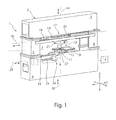
- FIG. 1 shows a machine tool 1, which is designed as a stamping press.
- This machine tool 1 comprises a support structure with a closed machine frame 2. This comprises two horizontal frame legs 3, 4 and two vertical frame legs 5 and 6.
- the machine frame 2 encloses a frame interior 7, the working area of the machine tool 1 with an upper tool 11 and a lower tool. 9 forms.
- the machine tool 1 is used for processing plate-shaped workpieces 10, which are not shown in Figure 1 for the sake of simplicity and can be arranged for processing purposes in the frame interior 7.
- a workpiece 10 to be machined is placed on a workpiece support 8 provided in the frame interior 7.
- the lower tool 9 is mounted, for example in the form of a punching die on the lower horizontal frame leg 4 of the machine frame 2.
- This punching die can be provided with a die opening.
- the upper tool 11 and lower tool 9 can be used instead of a punch and a punching die as a punch and a bending die for forming workpieces 10.
- the upper tool 11 is fixed in a tool holder at a lower end of a plunger 12.
- the plunger 12 is part of a lifting drive device 13, by means of which the upper tool 11 can be moved in a stroke direction along a lifting axis 14.
- the lifting axis 14 extends in the direction of the Z-axis of the coordinate system of a indicated in Figure 1 numerical control 15 of the machine tool 1.
- Perpendicular to the lifting axis 14, the lifting drive device 13 along a positioning axis 16 are moved in the direction of the double arrow.
- the positioning axis 16 extends in the direction of the Y-direction of the coordinate system of the numerical control 15.
- the lifting tool 13 receiving the upper tool 11 is moved by means of a motor drive 17 along the positioning axis 16.
- the movement of the plunger 12 along the lifting axis 14 and the positioning of the lifting drive device 13 along the positioning axis 16 by means of a motor drive 17 in the form of a drive assembly 17, in particular spindle drive assembly, with a running in the direction of the positioning axis 16 and fixedly connected to the machine frame 2 drive spindle 18.
- the lifting drive device 13 is guided during movements along the positioning axis 16 on three guide rails 19 of the upper frame leg 3, of which two guide rails 19 can be seen in FIG.
- the one remaining guide rail 19 is parallel to the visible guide rail 19 and is spaced therefrom in the direction X-axis of the coordinate system of the numerical control 15.
- On the guide rails 19 run guide shoes 20 of the Hubantriebsvorraum 13.
- the mutual engagement of the guide rail 19 and the guide shoes 20 is such that this connection between the guide rails 19 and the guide shoes 20 can also absorb a load acting in the vertical direction. Accordingly, the lifting device 13 is suspended via the guide shoes 20 and the guide rails 19 on the machine frame 2. Another component of the lifting drive device 13 is a wedge gear 21, by which a position of the upper tool 11 is adjustable relative to the lower tool 9.
- the lower tool 9 is received movably along a lower positioning axis 25.
- This lower positioning axis 25 extends in the direction of the Y-axis of the coordinate system of the numerical control 15.
- the lower positioning axis 25 is aligned parallel to the upper positioning axis 16.
- the lower tool 9 can be moved directly on the lower positioning axis 16 with a motor drive arrangement 26 along the positioning axis 25.
- the lower tool 9 can also be provided on a lifting drive device 27, which can be moved along the lower positioning axis 25 by means of the motor drive arrangement 26.
- This drive arrangement 26 is preferably designed as a spindle drive arrangement.
- the lower lift drive device 27 may correspond in structure to the upper lift drive device 13.
- the motor drive assembly 26 may correspond to the motor drive assembly 17.
- the lower lifting drive device 27 is also displaceably mounted on a lower horizontal frame leg 4 associated guide rails 19.
- Guide shoes 20 of the lifting drive device 27 run on the guide rails 19, so that the connection between the guide rails 19 and guide shoes 20 on the lower tool 9 can also absorb a load acting in the vertical direction. Accordingly, the lifting drive device 27 is suspended via the guide shoes 20 and the guide rails 19 on the machine frame 2 and at a distance from the guide rails 19 and guide shoes 20 of the upper lifting drive device 13.
- the lifting drive device 27 may include a wedge gear 21, by which the position or height of the lower tool 9 along the Z-axis is adjustable.
- both the motor drives 17 for a movement of the upper tool 11 along the upper positioning axis 16, as well as the one or more motor drives 26 for a movement of the lower tool 9 along the lower positioning axis 25 are controlled independently.
- the upper and lower tool 11, 9 can be moved synchronously in the direction of the Y-axis of the coordinate system.
- an independent movement of the upper and lower tool 11, 9 are also driven in different directions.
- This independent movement of the upper and lower tool 11, 9 can be controlled at the same time.
- the upper and lower tool 11, 9 may be formed for machining the workpieces 10 in a variety of ways.
- the wedge gear 21 comprises two drive-side wedge gear elements 122, 123, and two output-side wedge gear elements 124, 125. The latter are structurally combined to form a structural unit in the form of a driven-side double wedge 126.
- the plunger 12 is rotatably mounted about the lifting axis 14.
- a motor rotary drive device 128 is housed in the output side double wedge 126 and moves the plunger 12 when necessary along the lifting axis 14.
- a plunger bearing 129 is shown schematically.
- the plunger bearing 129 allows low-friction rotational movements of the plunger 12 about the lifting axis 14, on the other hand supports the plunger bearing 129 the plunger 12 in the axial direction and accordingly carries loads acting on the plunger 12 in the direction of the lifting axis 14, in the output side double wedge 126th from.
- the driven-side double wedge 126 is limited by a wedge surface 130, and by a wedge surface 131 of the output-side gear element 125.
- the wedge surfaces 130, 131 of the output-side wedge gear elements 124, 125 are opposed by wedge surfaces 132, 133 of the drive-side wedge gear elements 122, 123.
- longitudinal guides 134, 135 the drive-side wedge gear member 122 and the output side wedge gear member 124 and the drive side wedge gear member 123 and the driven side wedge gear member 125 in the direction of the Y-axis, that is, in the direction of the positioning axis 16 of the Hubantriebsvorraumraum 13, guided relative to each other movable.
- the drive-side wedge gear element 122 has a motor drive unit 138, the drive-side wedge gear element 123 via a motor drive unit 139. Both drive units 138, 139 together form the spindle drive arrangement 17th
- motor drive units 138, 139 Common to the motor drive units 138, 139 is the drive spindle 18 shown in FIG. 1 as well as the lifting drive device 13, 27 mounted on the machine frame 2 and consequently supporting structure side.
- the drive-side wedge gear elements 122, 123 are operated such that they move along the positioning axis 16, for example, which results in a relative movement between the drive-side wedge gear elements 122, 123 on the one hand and the output side wedge gear elements 124, 125 on the other hand , As a result of this relative movement of the output side double wedge 126 and the ram 12 mounted thereon is moved along the lifting axis 14 down.
- the punch mounted on the plunger 12, for example, as an upper tool 11 performs a working stroke and thereby machined on the workpiece support 28, 29 and the workpiece support 8 mounted workpiece 10.
- the plunger 12 is again along the Lifting axle 14 is raised or moved upwards.
- the above-described lifting drive device 13 according to FIG. 2 is preferably constructed identically as the lower lift drive device 27 and accommodates the lower tool 9.
- FIG. 3 shows a schematic diagram of a possible stroke movement of the plunger 12.
- the diagram shows a stroke course along the Y-axis and the Z-axis.
- an oblique lifting movement of the Hubst formulateels 12 down to the workpiece 10 to be driven as shown by the first straight line A.
- the plunger 12 can be lifted vertically, for example, as shown by the straight line B.
- an exclusive movement takes place along the Y-axis in accordance with the straight line C, in order to position the plunger 12 for the workpiece 10 for a new working position.
- the work sequence described above can be repeated. If, for a subsequent processing step, the workpiece 10 is moved on the workpiece support surface 28, 29, a movement along the straight line C can also be dispensed with.
- the illustrated in the diagram in Figure 3 possible stroke movement of the plunger 12 on the upper tool 11 is preferably combined with a stationary held lower tool 9.
- the lower tool 9 is positioned within the machine frame 2 such that at the end of a working stroke of the upper tool 11, the upper and lower tool 11, 9 occupy a defined position.
- This exemplary superimposed stroke course can be controlled both for the upper tool 11 and the lower tool 9.
- a superimposed lifting movement of the upper tool and / or lower tool 11, 9 can be actuated.
- FIG. 4 shows a schematic diagram illustrating a lifting movement of the plunger 12 according to the exemplary illustrated line D along a Y-axis and a Z-axis.
- a lifting movement of the plunger 12 can undergo a curve or arc curve by a superposition of the movements in the Y direction and Z direction is controlled accordingly by the controller 15.
- Such a flexible superimposition of the movement movements in the X and Z directions allows specific machining tasks to be solved.
- the control of such a curve can be provided for the upper tool 11 and / or lower tool 9.
- FIG. 5 shows a schematic view of the machine tool 1 according to FIG.
- the workpiece support 28 may for example be assigned to a loading station, not shown, through which unprocessed workpieces 10 are placed on the workpiece support surface 28.
- Adjacent to the workpiece support surface 28, 29 is a feed device 22, which comprises a plurality of grippers 23 in order to grasp the workpiece 10 placed on the workpiece support 28.
- the feed device 22 By means of the feed device 22, the workpiece 10 is passed through the machine frame 2 in the X direction.
- the feed device 22 can also be moved in the Y direction. As a result, a free movement of the workpiece 10 in the X-Y plane can be provided.
- the workpiece 10 can be moved by the feed device 22 both in the X direction and counter to the X direction.
- This movement of the workpiece 10 can be adapted to a movement of the upper tool 11 and lower tool 9 in and counter to the Y direction for the respective processing task.
- the workpiece support 28 opposite the other workpiece support 29 is provided on the machine frame 2. This may for example be associated with an unloading station. Alternatively, the loading and unloading of the unprocessed workpiece 10 and machined workpiece 10 with workpieces 81 may also be assigned to the same workpiece support 28, 29.
- the machine tool 1 can furthermore have a laser processing device 201, in particular a laser cutting machine, which is shown only schematically in a plan view in FIG.
- This laser processing device 201 can be designed, for example, as a CO 2 laser cutting machine.
- the laser processing device 201 comprises a laser source 202, which generates a laser beam 203, which is guided by means of a beam guide 204 shown schematically to a laser processing head, in particular laser cutting head 206, and focused in this. Thereafter, the laser beam 204 is aligned by a cutting nozzle perpendicular to the surface of the workpiece 10 to machine the workpiece 10.
- the laser beam 203 preferably acts on the workpiece 10 at the processing location, in particular the cutting location, together with a process gas jet. The cutting point at which the laser beam 203 impinges on the workpiece 10 is adjacent to the processing point of the upper tool 11 and lower tool.
- the laser cutting head 206 can be moved by a linear drive 207 with a linear axis system at least in the Y direction, preferably in the Y and Z directions.
- This linear axis system which receives the laser cutting head 206, may be associated with, attached to, or integrated with the machine frame 2.
- a beam passage opening may be provided in the workpiece support 28.
- a beam collecting device for the laser beam 21 may be provided below the beam passage opening.
- the beam passage opening and optionally the beam collecting device can also be designed as a structural unit.
- the laser processing device 201 may also comprise a solid-state laser as the laser source 202, the radiation of which is guided to the laser cutting head 206 by means of a light-conducting cable.
- the workpiece support 28, 29 may extend directly to the workpiece support 8, which surrounds the lower tool 9 at least partially. Within a free space resulting therebetween, the lower tool 9 is movable along the lower positioning axis 25 in and counter to the Y direction.
- the workpiece support 28 is for example a machined workpiece 10, in which a workpiece part 81 is cut free from a cutting gap 83, for example by a punching or by a laser beam processing to a residual compound 82.
- the workpiece 81 is held in the workpiece 10 and the remaining skeleton.
- the workpiece 10 is positioned by means of the feed device 22 to the upper and lower tool 11, 9 for a stamping and Ausschleus suits.
- the residual compound 82 is separated by a punching stroke of the upper tool 11 to the lower tool 9.
- the workpiece part 81 can be discharged, for example, by partially lowering the workpiece support 8 down.
- the cut-free workpiece part 81 can be transferred back to the workpiece support 28 or onto the workpiece support 29 in order to unload the workpiece part 81 and the residual grid.
- small workpiece parts 81 may optionally be discharged through an opening in the lower tool 9.
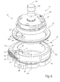
- FIG. 6 shows a perspective view of the tool 31 consisting of an upper tool 11, which is formed for example as a punch and a lower tool 9, which is formed for example as a punching die.
- the upper tool 11 comprises a base body 33 with a clamping shaft 34 and an adjusting or indexing element or adjusting or indexing wedge 36.
- the clamping shaft 34 serves to hold the upper tool 11 in the machine-side upper tool holder.
- the orientation of the upper tool 11 or the rotational position of the upper tool 11 is determined by the Indexierkeil 36.
- the orientation of the cutting tool 37 is adjusted on the main body 33 of the upper tool 11 and the upper tool 11 is aligned with the lower tool 9.
- the lower tool 9 also comprises a base body 41, which is adapted to be fixed in the machine-side lower tool holder with a defined rotational position, for example by at least one adjusting element 42nd
- the cutting tool 37 is provided on an underside of the main body 33 of the upper tool 11. This is for example round in cross-section and thus has a circular cutting edge 38. Alternatively it can be provided that the geometry of the cutting edge 38 is rectangular or square, or has a corresponding contour profile. Also, the cutting edge 38 may be formed on a slanted cutting tool 37.
- the cutting tool 37 may also include a cutting edge 38 with a hollow ground.
- the cutting tool 37 may have an end face 40. In the case of a slanted cutting tool 37, the end face 40 may also be inclined. In a cutting tool 37 with a hollow grinding, the end face 40 is formed by the peripheral cutting edge 38. This points to the lower tool 9 and is preferably limited by the cutting edge 38.
- the wiper 32 Associated with the upper tool 11 is the wiper 32, which has an opening 39, which may correspond in the geometry of the cut edge 38.
- This scraper 32 is received in the upper machine-side tool holder by guides, such as pins 44, so that it is also movable along the lifting axis 14 relative to the lower tool 9.
- guides such as pins 44
- the wiper 32 can be moved simultaneously with the upper tool 11 along the lifting axis 14 and perform a stripping movement after lifting from the lower tool 9.
- the lower tool 9 has in the main body 41 an opening 46 which is bounded by a peripheral bearing surface 47.
- the bearing surface 47 may also extend only in sections or be formed by a plurality of elements.
- the opening 46 has a circular contour. This can also be designed differently.
- a cutting plate 49 is provided on the base body 41 of the lower tool 9.
- This cutting plate 49 is preferably designed detachably as a cutting insert.
- This cutting plate 49 has, according to the first embodiment, an inner counter-cutting edge 51 which is aligned and arranged towards the opening 46.
- the cutting plate 49 has an outer counter-cutting edge 52.
- the outer counter-cutting edge 52 may be aligned with an outer side bounding the bearing surface 47 or provided on this outer side.
- the inner counter-cutting edge and the outer counter-cutting edge 51, 52 are each formed on a separate cutting plate 49.
- the bearing surface 47 can be flush in the counter cutting edge 51, 52 pass.
- the counter-cutting edge 51, 52 is lower than the support surface 47 in order to avoid damage, such as scratches on the underside of the sheet metal.
- the counter cutting edge 51, 52 may be aligned flush with an end face or a flat 57 or a protective strip 59 or slightly protruding.
- the bearing surface 47 may be formed in a region adjoining the cutting plate 49 such that the bearing surface 47 in the annular width corresponds at least to the length of the cutting plate 49.
- the inner counter-cutting edge 51 is arranged on a projection 53 projecting in the direction of the opening 46.
- a discharge surface 55 is provided which is associated with the outer counter-cutting edge 52.
- This discharge surface 55 is preferably sloping towards the support surface 47 sloping outward.
- workpiece parts 81 which have been cut free via the outer counter-cutting edge 52 can be discharged to the outside via the discharge surface 55 in order, for example, to supply a collecting container or waste container.
- the discharge surface 55 is preferably exchangeably fixed to the base body 41 of the lower tool 9. In the exemplary embodiment it is provided that the discharge surface 55 has a web portion not shown, which extends below the cutting plate 49, so that the discharge surface 55 is held by clamping after attachment of the cutting plate 49 in the base body 41.
- the discharge surface 55 is recessed relative to the outer cutting edge 52 about a Abstanzization 56.
- the main body 41 of the lower tool 9 has flush with the Abstanzization 56 of the cutting plate 49 and laterally adjacent flats 57.
- the flats 59 are aligned tangentially to the opening 46.
- a ramp 56 is provided on the base body 41 of the lower tool 9.
- This run-on slope 58 flows smoothly into the bearing surface 47.
- This run-on slope 58 is limited by the flattening 57.
- a roof-shaped course is formed in a side view of the Abstanzization 56 and outer counter-cutting edge 52 .
- a radially outer edge of the run-on slope 58 is recessed relative to the support surface 47.
- the run-up slope 58 extends, starting from the outer counter-cutting edge 52, at least in an angular range of at least 30 ° relative to the position axis 48. Preferably, the run-up slope 58 extends, starting from the outer counter-cutting edge 52, by up to 90 °.
- the ramps 58 may also be provided interchangeably on the main body 41.
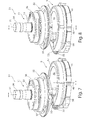
- FIG. 7 shows a first working position of the tool 31, in which the upper tool 11 is associated with the cutting tool 37 of an outer counter-cutting edge 52 of the lower tool 9.
- 8 shows a perspective side view of a further working position of the tool 31, in which the cutting tool 37 of the upper tool 11 is aligned with the inner counter-cutting edge 51 of the lower tool 9.
- FIG. 9 shows a perspective view of an alternative embodiment of the tool 31 to FIG. 6.
- an upper tool 11 is provided, which has a cutting tool 37 with a rectangular cutting edge 38.
- Such an upper tool 11 can also be used with a lower tool 9 according to FIG.
- the lower tool 9 in FIG. 9 differs from the lower tool 9 according to FIG. 4 in that the inner and outer counter-cutting edges 51, 52 are formed separately from one another and that they are also positioned offset relative to one another in the angular position relative to the opening 46 on the main body 41.
- the inner counter-cutting edge 51 and the outer counter-cutting edge 52 is offset by 180 ° to each other on the base body 41.
- the inner and outer counter cutting edge 51, 52 may also be aligned in other angular positions. Also, a plurality of inner and / or outer counter cutting edges 51, 52 may be provided on the lower tool 9. The number of inner and outer counter cutting edges 51, 52 may also differ from each other. Each of these cutting edges 38 and counter cutting edges 51, 52 may have a different distance to the position axis 35, 48 of the respective upper tool 11 and lower tool 9. The inner and / or outer cutting edges 38 and counter cutting edges 51, 52 may also have a closed contour.
- the inner counter-cutting edge 51 is formed directly on the base body 41.
- the outer counter-cutting edge 52 is releasably secured to the base body 41.
- the inner counter-cutting edge 51 is associated with a ramp 56.
- this run-on slope 58 can also be assigned to the outer counter-cutting edge 52.
- FIG. 10 shows a perspective view of an alternative embodiment of the lower tool 9 for a tool 31 according to FIG.
- the inner counter-cutting edge 51 and the outer counter-cutting edge 52 are each formed as a detachable cutting plate 49. Preferably, these are also arranged separately from each other on the base body 41 or aligned with the support surface 47.
- the run-on slope 58 is attached as a detachable attachment to the base body 41 and the inner and outer counter-cutting edge 51, 52 are enclosed in the run-on slope 58.
- the outer cutting edge 52 on one side or on both sides of a protective strip 59 may be assigned, which is preferably resiliently held.
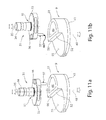
- FIGS. 11 a and 11 b show a further alternative embodiment of the tool 31 to FIG. 6, wherein FIG. 11 a shows a first working position and FIG. 11 b shows a second working position of the tool 31.
- the upper tool 11 is provided, which corresponds to the embodiment in Figure 6.
- the lower tool 9 differs from the embodiment in FIG. 4 in that the opening 46 is semicircular or arc segment-shaped.
- an outer counter-cutting edge 52 can be formed, which extends along the remaining diameter. Adjacent to the outer counter-cutting edge 52, the discharge surface 55 can be formed.
- This embodiment has the advantage that a very long outer counter cutting edge 52 can be formed.
- a boundary of the opening 46 can be formed as an inner counter-cutting edge 51.
- FIG. 12 shows a further alternative embodiment of the lower tool 9 for a tool 31 for FIG. 6.
- an inner counter-cutting edge 51 is provided in this lower tool 9 on the main body 41.
- This can also be designed as an insertable insert 49.
- an exchangeable adapter plate 61 is provided with at least one outer counter cutting edge 52.
- the outer counter-cutting edge 52 consists for example of three individual secondary cutting edges. The secondary cutting edges may be trapezoidal or otherwise aligned with each other.
- Such a lower tool 9 allows an increase in the flexibility with respect to the working position of the upper tool 11 to the outer counter-cutting edge 52.
- FIGS. 13 a to 13 d show various working positions in the plan view of the lower tool 9 according to FIG. 12 with a hexagonal cutting tool 37 of the upper tool 11, for example.
- FIG. 13 a shows a working position in which a cutting edge 38 of the cutting tool 37 is assigned to the inner counter-cutting edge 51.
- FIG. 13b differs from FIG. 13a in that, for example, the lower tool 9 is rotated about its position axis 48, without the lower tool 9 having been moved in at least one direction of travel.
- the upper tool 11 can be aligned with the inner counter-cutting edge 51 by means of a rotational movement about its position axis 35 and an optionally required traversing movement along a positioning axis 16.
- FIG. 13 c shows a positioning of the cutting tool 37 of the upper tool 11 to the outer counter-cutting edge 52 of the lower tool 9, in particular in alignment with a secondary cutting edge.
- FIG. 13 d shows another alternative working position of the cutting tool 37 of the upper tool 11 with respect to the lower tool 9. It can be seen in comparison with FIG. 13c that the cutting position can be changed in a simple manner by a corresponding alignment or rotation of the lower tool 9 about the position axis 48 and an assignment of the upper tool 11.
- FIG. 14 shows a perspective view of an alternative embodiment of the tool 31 to FIGS. 11 a and 11 b.
- the lower tool 9 in this embodiment corresponds to the figures 11 a and 11 b. In that regard, reference is made to this description in full.
- a punch which is designed as a multiple tool.
- Such a multiple tool comprises a plurality of cutting tools 37.
- These cutting tools 37 each have a cutting edge 38, wherein these differ in shape and geometry from each other.
- These cutting tools 37 are received as punch inserts in the base body 33.
- an activation device 75 Associated with the main body 33 is an activation device 75, which has, for example, an external toothing 76.
- a machine-side rotary drive which is preferably provided on the tool holder, there is a control for a rotary movement of the activation device 75 about the position axis 35.
- open contours in the workpiece 10 can be cut.
- Such open contours may be, for example, a residual connection 82, such as a microjoint.
- individual workpiece parts 81 may be cut free from the workpiece 10 by one or more working strokes.
- such open contours can be formed by the introduction of a cutting gap 83, wherein a plurality of working strokes may be provided to form the cutting gap 83 or punch out a waste part or a good part as a workpiece part 81. Due to the independent movement of the upper tool 11 to the lower tool 9 can be given a simple adaptation to the thickness of the workpiece to be machined 10 at the same cutting tool 37 and the at least one counter cutting edge 51, 52.
Landscapes
- Engineering & Computer Science (AREA)
- Mechanical Engineering (AREA)
- Life Sciences & Earth Sciences (AREA)
- Forests & Forestry (AREA)
- Punching Or Piercing (AREA)
- Milling Processes (AREA)
Priority Applications (5)
| Application Number | Priority Date | Filing Date | Title |
|---|---|---|---|
| EP17783413.2A EP3515622B1 (de) | 2016-09-26 | 2017-09-26 | Werkzeug und werkzeugmaschine sowie verfahren zum schneiden und/oder umformen von plattenförmigen werkstücken |
| CN201780059078.2A CN109789471B (zh) | 2016-09-26 | 2017-09-26 | 用于切割和/或成型板状的工件的工具和机床以及方法 |
| JP2019515820A JP7051825B2 (ja) | 2016-09-26 | 2017-09-26 | 板状工作物の切断および/または変形のための工具および工具機械並びに方法 |
| PL17783413T PL3515622T3 (pl) | 2016-09-26 | 2017-09-26 | Narzędzie oraz obrabiarka, jak również sposób cięcia i/lub odkształcania przedmiotów obrabianych mających postać płyt |
| US16/363,167 US11241727B2 (en) | 2016-09-26 | 2019-03-25 | Machining planar workpieces |
Applications Claiming Priority (4)
| Application Number | Priority Date | Filing Date | Title |
|---|---|---|---|
| DE102016118175.7 | 2016-09-26 | ||
| DE102016118175.7A DE102016118175B4 (de) | 2016-09-26 | 2016-09-26 | Werkzeugmaschine und Verfahren zum Bearbeiten von plattenförmigen Werkstücken |
| DE102016119434.4 | 2016-10-12 | ||
| DE102016119434.4A DE102016119434A1 (de) | 2016-10-12 | 2016-10-12 | Werkzeug und Werkzeugmaschine sowie Verfahren zum Schneiden und/oder Umformen von plattenförmigen Werkstücken |
Related Child Applications (1)
| Application Number | Title | Priority Date | Filing Date |
|---|---|---|---|
| US16/363,167 Continuation US11241727B2 (en) | 2016-09-26 | 2019-03-25 | Machining planar workpieces |
Publications (1)
| Publication Number | Publication Date |
|---|---|
| WO2018055182A1 true WO2018055182A1 (de) | 2018-03-29 |
Family
ID=60080759
Family Applications (1)
| Application Number | Title | Priority Date | Filing Date |
|---|---|---|---|
| PCT/EP2017/074296 Ceased WO2018055182A1 (de) | 2016-09-26 | 2017-09-26 | Werkzeug und werkzeugmaschine sowie verfahren zum schneiden und/oder umformen von plattenförmigen werkstücken |
Country Status (6)
| Country | Link |
|---|---|
| US (1) | US11241727B2 (enExample) |
| EP (1) | EP3515622B1 (enExample) |
| JP (1) | JP7051825B2 (enExample) |
| CN (1) | CN109789471B (enExample) |
| PL (1) | PL3515622T3 (enExample) |
| WO (1) | WO2018055182A1 (enExample) |
Cited By (2)
| Publication number | Priority date | Publication date | Assignee | Title |
|---|---|---|---|---|
| DE102019129787A1 (de) * | 2019-11-05 | 2021-05-06 | Trumpf Werkzeugmaschinen Gmbh + Co. Kg | Werkzeug und Verfahren zum Bearbeiten von plattenförmigen Werkstücken, insbesondere von Blechen |
| CN120696289A (zh) * | 2025-08-27 | 2025-09-26 | 中科创源(山西)智能科技有限公司 | 一种门锁加工用冲压装置 |
Families Citing this family (3)
| Publication number | Priority date | Publication date | Assignee | Title |
|---|---|---|---|---|
| DE102019119849A1 (de) | 2019-07-23 | 2021-01-28 | Trumpf Werkzeugmaschinen Gmbh + Co. Kg | Werkzeug und Verfahren zum Bearbeiten von plattenförmigen Werkstücken |
| DE102019119848A1 (de) | 2019-07-23 | 2021-01-28 | Trumpf Werkzeugmaschinen Gmbh + Co. Kg | Werkzeug und Verfahren zum Bearbeiten von plattenförmigen Werkstücken, insbesondere Blechen |
| US12441076B2 (en) * | 2022-10-18 | 2025-10-14 | Slavoljub Stojanovski | Stamping apparatus |
Citations (5)
| Publication number | Priority date | Publication date | Assignee | Title |
|---|---|---|---|---|
| DE4235972A1 (de) | 1992-10-26 | 1994-04-28 | Pass Anlagenbau Gmbh | Schneid-Werkzeug, insbesondere für Stanz- und Nibbelautomaten |
| DE102006049044A1 (de) | 2006-10-18 | 2008-04-24 | Trumpf Werkzeugmaschinen Gmbh + Co. Kg | Werkzeug zum Bearbeiten von plattenartigen Werkstücken |
| DE202008003915U1 (de) * | 2008-03-19 | 2008-05-29 | Trumpf Werkzeugmaschinen Gmbh + Co. Kg | Ausstoßwerkzeug zum Bearbeiten von Werkstücken |
| EP2177289B1 (de) | 2008-10-20 | 2011-07-06 | TRUMPF Werkzeugmaschinen GmbH + Co. KG | Werkzeugmaschinen und Verfahren zum Ausschleusen eines Werkstückteils |
| EP2527058B1 (de) | 2011-05-26 | 2014-07-16 | TRUMPF Werkzeugmaschinen GmbH + Co. KG | Werkzeugmaschine in Form einer Presse zum Bearbeiten von Werkstücken, insbesondere von Blechen |
Family Cites Families (36)
| Publication number | Priority date | Publication date | Assignee | Title |
|---|---|---|---|---|
| US522953A (en) * | 1894-07-10 | Die and process of making dies | ||
| US2035448A (en) * | 1932-08-05 | 1936-03-31 | Andersson Nils Fredrik Filemon | Apparatus for cutting sheet metal or the like |
| US2684717A (en) * | 1952-03-10 | 1954-07-27 | Tucker Smith G | Card perforating device |
| US3269240A (en) * | 1965-03-29 | 1966-08-30 | John S Killaly | Quadrant punch for turret punch presses and the like |
| US3370492A (en) * | 1965-04-02 | 1968-02-27 | Smithe Machine Co Inc F L | Die cutting presses |
| US3613491A (en) * | 1969-09-15 | 1971-10-19 | Manfred Kahmann | Punching machine |
| US3785236A (en) * | 1972-05-30 | 1974-01-15 | Hager & Sons Hinge Mfg | Impact die and carbide insert therefor |
| PL122194B1 (en) * | 1979-04-13 | 1982-06-30 | Politechnika Lodzka | Blanking die |
| US4343210A (en) * | 1979-05-31 | 1982-08-10 | Anritsu Electric Co Ltd | Punch press |
| DE3410913A1 (de) * | 1984-03-24 | 1985-10-03 | Trumpf GmbH & Co, 7257 Ditzingen | Werkzeugmaschine zur mechanischen und laserstrahl-bearbeitung eines werkstuecks |
| US4738173A (en) * | 1986-11-03 | 1988-04-19 | U.S. Amada Limited | Shearing in punch press and die therefor |
| US4929276A (en) * | 1989-05-22 | 1990-05-29 | Murata Wiedemann, Inc. | Multitool punch holder |
| JPH07108420B2 (ja) * | 1990-09-14 | 1995-11-22 | 株式会社小松製作所 | タレットパンチプレスの追切り加工方法 |
| US5195413A (en) * | 1991-08-16 | 1993-03-23 | Mate Punch & Die Co. | Shearing tool for punch presses |
| JP2597055Y2 (ja) * | 1993-07-19 | 1999-06-28 | 株式会社アマダ | パンチプレス |
| JP2611128B2 (ja) * | 1993-08-17 | 1997-05-21 | 株式会社アマダメトレックス | 追切り用切断金型 |
| US5392629A (en) * | 1993-10-26 | 1995-02-28 | Canoga Industries Inc. | Method and apparatus for forming multi-level features in an object |
| US6189361B1 (en) * | 1997-09-04 | 2001-02-20 | Amada Metrecs Company Limited | Tool for forming protrusions in material by cutting and deforming |
| KR20010032746A (ko) * | 1997-12-03 | 2001-04-25 | 피어리스 머신 앤드 툴 코포레이션 | 성형위치에서 압축지를 절단하는 다이 |
| US6125520A (en) * | 1999-04-19 | 2000-10-03 | Thyssen Elevator Holding Corporation | Shake and break process for sheet metal |
| JP2000343144A (ja) * | 1999-06-04 | 2000-12-12 | Denso Corp | プレス成形品の製造方法 |
| DE19954441A1 (de) * | 1999-08-13 | 2001-02-15 | Thyssenkrupp Ind Ag | Vorrichtung zur Betätigung eines Stößels in einer Hub- oder Spannvorrichtung, insbesondere zum Falzen von Blechen im Automobilbau |
| JP2001252726A (ja) * | 2000-03-10 | 2001-09-18 | Murata Mach Ltd | 長尺材加工機 |
| GB2360727B (en) * | 2000-03-30 | 2004-02-04 | Tradewise Engineering Ltd | Modular unit for converting punching machines from single-punch to multiple-punch |
| JP2001321851A (ja) * | 2000-05-19 | 2001-11-20 | Amada Co Ltd | ダイ装置 |
| DE20020499U1 (de) * | 2000-12-02 | 2001-03-15 | Trumpf GmbH + Co., 71254 Ditzingen | Werkzeug zum Schlitzen von plattenartigen Werkstücken |
| JP4279532B2 (ja) * | 2002-10-01 | 2009-06-17 | 株式会社アマダ | 成形製品の加工方法に使用する金型装置及び下金型 |
| DE102006049046A1 (de) * | 2006-10-18 | 2008-04-24 | Trumpf Werkzeugmaschinen Gmbh + Co. Kg | Werkzeug und Werkzeugmaschine zum Bearbeiten von plattenartigen Werkstücken, insbesondere von Blechen |
| EP2764933B1 (de) * | 2008-12-10 | 2016-10-05 | TRUMPF Werkzeugmaschinen GmbH + Co. KG | Werkzeugsystem mit auswechselbaren Werkzeugeinsätzen für Stanzmaschinen |
| DE202009004014U1 (de) * | 2009-03-25 | 2009-06-04 | Trumpf Werkzeugmaschinen Gmbh + Co. Kg | Stanzwerkzeug und Werkzeugmaschine damit |
| JP6019821B2 (ja) * | 2012-07-02 | 2016-11-02 | 村田機械株式会社 | 追い抜き加工用金型 |
| JP2014018801A (ja) * | 2012-07-12 | 2014-02-03 | Honda Motor Co Ltd | 孔開け加工方法、孔を備えた構造体の製造方法および孔を備えた構造体 |
| DE102014205249B4 (de) * | 2014-03-20 | 2017-11-16 | Trumpf Werkzeugmaschinen Gmbh + Co. Kg | Werkzeug für eine Universalstanzmaschine, Universalstanzmaschine mit einem solchen Werkzeug sowie Verfahren zum Betreiben einer Universalstanzmaschine mit einem solchen Werkzeug |
| CN104259293B (zh) * | 2014-08-15 | 2016-05-04 | 宁波宏协承汽车部件有限公司 | 一种汽车门框中柱外板的冲压切割装置 |
| PL3106241T3 (pl) | 2015-06-19 | 2018-01-31 | Trumpf Werkzeugmaschinen Gmbh Co Kg | Obrabiarka oraz sposób odprowadzania części przedmiotu obrabianego |
| CN109789470B (zh) * | 2016-09-26 | 2022-02-25 | 通快机床两合公司 | 用于加工板状工件的工具和机床以及方法 |
-
2017
- 2017-09-26 CN CN201780059078.2A patent/CN109789471B/zh active Active
- 2017-09-26 JP JP2019515820A patent/JP7051825B2/ja active Active
- 2017-09-26 EP EP17783413.2A patent/EP3515622B1/de active Active
- 2017-09-26 WO PCT/EP2017/074296 patent/WO2018055182A1/de not_active Ceased
- 2017-09-26 PL PL17783413T patent/PL3515622T3/pl unknown
-
2019
- 2019-03-25 US US16/363,167 patent/US11241727B2/en active Active
Patent Citations (5)
| Publication number | Priority date | Publication date | Assignee | Title |
|---|---|---|---|---|
| DE4235972A1 (de) | 1992-10-26 | 1994-04-28 | Pass Anlagenbau Gmbh | Schneid-Werkzeug, insbesondere für Stanz- und Nibbelautomaten |
| DE102006049044A1 (de) | 2006-10-18 | 2008-04-24 | Trumpf Werkzeugmaschinen Gmbh + Co. Kg | Werkzeug zum Bearbeiten von plattenartigen Werkstücken |
| DE202008003915U1 (de) * | 2008-03-19 | 2008-05-29 | Trumpf Werkzeugmaschinen Gmbh + Co. Kg | Ausstoßwerkzeug zum Bearbeiten von Werkstücken |
| EP2177289B1 (de) | 2008-10-20 | 2011-07-06 | TRUMPF Werkzeugmaschinen GmbH + Co. KG | Werkzeugmaschinen und Verfahren zum Ausschleusen eines Werkstückteils |
| EP2527058B1 (de) | 2011-05-26 | 2014-07-16 | TRUMPF Werkzeugmaschinen GmbH + Co. KG | Werkzeugmaschine in Form einer Presse zum Bearbeiten von Werkstücken, insbesondere von Blechen |
Cited By (2)
| Publication number | Priority date | Publication date | Assignee | Title |
|---|---|---|---|---|
| DE102019129787A1 (de) * | 2019-11-05 | 2021-05-06 | Trumpf Werkzeugmaschinen Gmbh + Co. Kg | Werkzeug und Verfahren zum Bearbeiten von plattenförmigen Werkstücken, insbesondere von Blechen |
| CN120696289A (zh) * | 2025-08-27 | 2025-09-26 | 中科创源(山西)智能科技有限公司 | 一种门锁加工用冲压装置 |
Also Published As
| Publication number | Publication date |
|---|---|
| PL3515622T3 (pl) | 2021-01-11 |
| US20190299272A1 (en) | 2019-10-03 |
| JP7051825B2 (ja) | 2022-04-11 |
| EP3515622B1 (de) | 2020-07-15 |
| CN109789471B (zh) | 2022-02-11 |
| EP3515622A1 (de) | 2019-07-31 |
| JP2019529123A (ja) | 2019-10-17 |
| US11241727B2 (en) | 2022-02-08 |
| CN109789471A (zh) | 2019-05-21 |
Similar Documents
| Publication | Publication Date | Title |
|---|---|---|
| EP3515622B1 (de) | Werkzeug und werkzeugmaschine sowie verfahren zum schneiden und/oder umformen von plattenförmigen werkstücken | |
| EP3515626B1 (de) | Werkzeugmaschine und verfahren zum bearbeiten von plattenförmigen werkstücken | |
| EP1740327B1 (de) | Verfahren zum entgraten von schnittkanten an werkstücken | |
| EP3515624A1 (de) | Verfahren; werkzeugmaschine und schlitzwerkzeug zum mehrhubig fortschreitenden schlitzen von plattenförmigen werkstücken | |
| EP3515623B1 (de) | Werkzeug und werkzeugmaschine sowie verfahren zum bearbeiten von plattenförmigen werkstücken | |
| EP3515618B1 (de) | Werkzeug und werkzeugmaschine sowie verfahren zur bearbeitung von plattenförmigen werkstücken | |
| WO2018055183A1 (de) | Werkzeug und werkzeugmaschine sowie verfahren zur bearbeitung von plattenförmigen werkstücken | |
| EP3515625A1 (de) | Werkzeug und werkzeugmaschine sowie verfahren zum bearbeiten von plattenförmigen werkstücken | |
| DE102016119435A1 (de) | Werkzeug und Werkzeugmaschine sowie Verfahren zum Bearbeiten von plattenförmigen Werkstücken | |
| EP3515628B1 (de) | Verfahren und werkzeugmaschine zum bearbeiten von plattenförmigen werkstücken, insbesondere von blechen | |
| EP3515617B1 (de) | Werkzeug und werkzeugmaschine sowie verfahren zum bearbeiten von plattenförmigen werkstücken | |
| DE3135266C2 (de) | Schneidpresse zum Herausschneiden oder -trennen von Teilen aus einer Werkstücktafel | |
| DE102016120139B4 (de) | Verfahren, Werkzeugmaschine und Schlitzwerkzeug zum mehrhubig fortschreitenden Schlitzen von plattenförmigen Werkstücken | |
| DE102016119464B4 (de) | Werkzeug und Werkzeugmaschine sowie Verfahren zur Bearbeitung von plattenförmigen Werkstücken | |
| EP2845663B1 (de) | Biegepresse mit einem Biegewerkzeug aus mehreren Werkzeugelementen | |
| DE102016120151A1 (de) | Verfahren und Werkzeugmaschine zum Bearbeiten von plattenförmigen Werkstücken, insbesondere von Blechen | |
| DE102016120141B3 (de) | Werkzeug und Werkzeugmaschine sowie Verfahren zum Bearbeiten von plattenförmigen Werkstücken | |
| DE102016119457A1 (de) | Werkzeug und Werkzeugmaschine sowie Verfahren zur Bearbeitung von plattenförmigen Werkstücken | |
| DE102016119434A1 (de) | Werkzeug und Werkzeugmaschine sowie Verfahren zum Schneiden und/oder Umformen von plattenförmigen Werkstücken | |
| WO2021013810A1 (de) | Werkzeug und verfahren zum bearbeiten von plattenförmigen werkstücken, insbesondere blechen | |
| WO2021013806A1 (de) | Werkzeug und verfahren zum bearbeiten von plattenförmigen werkstücken | |
| EP0261547A2 (de) | Funkenerosionsmaschine für das Drahterodieren | |
| DE102006051245A1 (de) | Fertigungseinrichtung | |
| DE102016120035B3 (de) | Werkzeug und Werkzeugmaschine sowie Verfahren zum Bearbeiten von plattenförmigen Werkstücken | |
| DE102016120142A1 (de) | Werkzeugmaschine und Verfahren zum Bearbeiten von plattenförmigen Werkstücken |
Legal Events
| Date | Code | Title | Description |
|---|---|---|---|
| 121 | Ep: the epo has been informed by wipo that ep was designated in this application |
Ref document number: 17783413 Country of ref document: EP Kind code of ref document: A1 |
|
| ENP | Entry into the national phase |
Ref document number: 2019515820 Country of ref document: JP Kind code of ref document: A |
|
| WWE | Wipo information: entry into national phase |
Ref document number: 2017783413 Country of ref document: EP |