WO2018051986A1 - ハブユニット - Google Patents
ハブユニット Download PDFInfo
- Publication number
- WO2018051986A1 WO2018051986A1 PCT/JP2017/032918 JP2017032918W WO2018051986A1 WO 2018051986 A1 WO2018051986 A1 WO 2018051986A1 JP 2017032918 W JP2017032918 W JP 2017032918W WO 2018051986 A1 WO2018051986 A1 WO 2018051986A1
- Authority
- WO
- WIPO (PCT)
- Prior art keywords
- hub unit
- raceway surface
- inner shaft
- rolling element
- ring
- Prior art date
- Legal status (The legal status is an assumption and is not a legal conclusion. Google has not performed a legal analysis and makes no representation as to the accuracy of the status listed.)
- Ceased
Links
Images









Classifications
-
- F—MECHANICAL ENGINEERING; LIGHTING; HEATING; WEAPONS; BLASTING
- F16—ENGINEERING ELEMENTS AND UNITS; GENERAL MEASURES FOR PRODUCING AND MAINTAINING EFFECTIVE FUNCTIONING OF MACHINES OR INSTALLATIONS; THERMAL INSULATION IN GENERAL
- F16C—SHAFTS; FLEXIBLE SHAFTS; ELEMENTS OR CRANKSHAFT MECHANISMS; ROTARY BODIES OTHER THAN GEARING ELEMENTS; BEARINGS
- F16C33/00—Parts of bearings; Special methods for making bearings or parts thereof
- F16C33/30—Parts of ball or roller bearings
- F16C33/58—Raceways; Race rings
- F16C33/583—Details of specific parts of races
- F16C33/585—Details of specific parts of races of raceways, e.g. ribs to guide the rollers
-
- B—PERFORMING OPERATIONS; TRANSPORTING
- B60—VEHICLES IN GENERAL
- B60B—VEHICLE WHEELS; CASTORS; AXLES FOR WHEELS OR CASTORS; INCREASING WHEEL ADHESION
- B60B27/00—Hubs
- B60B27/02—Hubs adapted to be rotatably arranged on axle
-
- B—PERFORMING OPERATIONS; TRANSPORTING
- B60—VEHICLES IN GENERAL
- B60B—VEHICLE WHEELS; CASTORS; AXLES FOR WHEELS OR CASTORS; INCREASING WHEEL ADHESION
- B60B35/00—Axle units; Parts thereof ; Arrangements for lubrication of axles
- B60B35/02—Dead axles, i.e. not transmitting torque
-
- B—PERFORMING OPERATIONS; TRANSPORTING
- B60—VEHICLES IN GENERAL
- B60B—VEHICLE WHEELS; CASTORS; AXLES FOR WHEELS OR CASTORS; INCREASING WHEEL ADHESION
- B60B35/00—Axle units; Parts thereof ; Arrangements for lubrication of axles
- B60B35/12—Torque-transmitting axles
- B60B35/18—Arrangement of bearings
-
- F—MECHANICAL ENGINEERING; LIGHTING; HEATING; WEAPONS; BLASTING
- F16—ENGINEERING ELEMENTS AND UNITS; GENERAL MEASURES FOR PRODUCING AND MAINTAINING EFFECTIVE FUNCTIONING OF MACHINES OR INSTALLATIONS; THERMAL INSULATION IN GENERAL
- F16C—SHAFTS; FLEXIBLE SHAFTS; ELEMENTS OR CRANKSHAFT MECHANISMS; ROTARY BODIES OTHER THAN GEARING ELEMENTS; BEARINGS
- F16C19/00—Bearings with rolling contact, for exclusively rotary movement
- F16C19/02—Bearings with rolling contact, for exclusively rotary movement with bearing balls essentially of the same size in one or more circular rows
- F16C19/14—Bearings with rolling contact, for exclusively rotary movement with bearing balls essentially of the same size in one or more circular rows for both radial and axial load
- F16C19/18—Bearings with rolling contact, for exclusively rotary movement with bearing balls essentially of the same size in one or more circular rows for both radial and axial load with two or more rows of balls
- F16C19/181—Bearings with rolling contact, for exclusively rotary movement with bearing balls essentially of the same size in one or more circular rows for both radial and axial load with two or more rows of balls with angular contact
- F16C19/183—Bearings with rolling contact, for exclusively rotary movement with bearing balls essentially of the same size in one or more circular rows for both radial and axial load with two or more rows of balls with angular contact with two rows at opposite angles
- F16C19/184—Bearings with rolling contact, for exclusively rotary movement with bearing balls essentially of the same size in one or more circular rows for both radial and axial load with two or more rows of balls with angular contact with two rows at opposite angles in O-arrangement
- F16C19/186—Bearings with rolling contact, for exclusively rotary movement with bearing balls essentially of the same size in one or more circular rows for both radial and axial load with two or more rows of balls with angular contact with two rows at opposite angles in O-arrangement with three raceways provided integrally on parts other than race rings, e.g. third generation hubs
-
- F—MECHANICAL ENGINEERING; LIGHTING; HEATING; WEAPONS; BLASTING
- F16—ENGINEERING ELEMENTS AND UNITS; GENERAL MEASURES FOR PRODUCING AND MAINTAINING EFFECTIVE FUNCTIONING OF MACHINES OR INSTALLATIONS; THERMAL INSULATION IN GENERAL
- F16C—SHAFTS; FLEXIBLE SHAFTS; ELEMENTS OR CRANKSHAFT MECHANISMS; ROTARY BODIES OTHER THAN GEARING ELEMENTS; BEARINGS
- F16C2326/00—Articles relating to transporting
- F16C2326/01—Parts of vehicles in general
- F16C2326/02—Wheel hubs or castors
Definitions
- the present disclosure relates to a hub unit, and more particularly to a hub unit attached to a vehicle.
- the hub unit which is a bearing device for vehicles, includes an inner shaft and an outer ring.
- An inner ring is fixed to the end of the inner shaft on the vehicle side.
- the inner shaft and the inner ring have raceway surfaces on the outer periphery.
- the outer ring has a raceway surface on the inner circumference corresponding to the raceway surface of the inner shaft and the inner ring.
- a bearing space is formed between the inner shaft and the inner ring and the outer ring.
- a plurality of rows of rolling elements are arranged in the bearing space. The bearing space is sealed by a sealing device.
- Patent Document 1 describes that a large radial load is applied to the rolling element on the inner side of the vehicle in the hub unit when the vehicle is turning. Patent Document 1 also describes that the amount of heat generated by friction at the contact portion between the rolling element and the raceway surface increases as the rotational speed and load load of the hub unit increase. Therefore, in the hub unit of Patent Document 1, the contact angle of the inner-side rolling element is made smaller than the contact angle of the outer-side rolling element, thereby improving the radial load supporting ability of the inner-side rolling element and generating heat due to friction. The amount is reduced.
- Patent Document 1 discloses that the amount of heat generated converted from rotational torque (bearing torque) is reduced by making the contact angle of the inner-side rolling element smaller than the contact angle of the outer-side rolling element. .
- the hub unit of Patent Document 1 has room for further improvement in terms of both suppression of increase in rotational torque and improvement in rigidity.
- the present disclosure provides a hub unit capable of improving rigidity while suppressing an increase in rotational torque.
- the present disclosure provides a hub unit capable of improving the bearing life.
- the hub unit according to the present disclosure is attached to the vehicle.
- the hub unit includes an outer ring, an inner shaft, an inner ring, a plurality of first rolling elements, and a plurality of second rolling elements.
- the outer ring has a first outer raceway surface and a second outer raceway surface on the inner peripheral surface.
- the second outer raceway surface is disposed on the outer side in the vehicle width direction with respect to the first outer raceway surface in a state where the hub unit is attached to the vehicle.
- the inner shaft is disposed concentrically with the outer ring on the inner periphery of the outer ring, and a wheel is attached to the outer side in the vehicle width direction.
- the inner ring is press-fitted on the inner side in the vehicle width direction of the inner shaft.
- the inner ring has a first inner raceway surface on the outer peripheral surface.
- the first inner raceway surface corresponds to the first outer raceway surface.
- the inner shaft has a second inner raceway surface on the outer peripheral surface.
- the second inner raceway surface corresponds to the second outer raceway surface.
- the plurality of first rolling elements are disposed in the bearing space. The plurality of first rolling elements contact the first outer raceway surface and the first inner raceway surface with a contact angle smaller than 37 °.
- the bearing space is formed between the outer ring and the inner shaft on which the inner ring is mounted.
- the plurality of second rolling elements are disposed in the bearing space. The plurality of second rolling elements are in contact with the second outer raceway surface and the second inner raceway surface at a contact angle larger than 37 °.
- the contact angle of the first rolling element disposed inward in the vehicle width direction is smaller than 37 °, and the contact angle of the second rolling element disposed outward in the vehicle width direction is larger than 37 °.
- the axial gap determined by the degree of pushing the inner ring with respect to the inner shaft is ⁇ 0.1 mm or more and ⁇ 0.015 mm or less.
- the axial gap determined by the degree of pushing of the inner ring with respect to the inner shaft is ⁇ 0.065 mm or more and ⁇ 0.015 mm or less.
- the hub unit life can be kept high and the rigidity of the hub unit can be improved.
- the hub unit according to the present disclosure can improve the rigidity while suppressing an increase in rotational torque.
- FIG. 1 is a longitudinal sectional view showing a schematic configuration of a hub unit according to the embodiment.
- FIG. 2 is an enlarged view of the II-II portion of the hub unit shown in FIG.
- FIG. 3 is a side view of the hub unit according to the embodiment.
- FIG. 4 is a view of the hub unit according to the embodiment as viewed from the inner side in the axial direction.
- FIG. 5 is a view of the hub unit according to the embodiment as viewed from the outer side in the axial direction.
- FIG. 6 is a view of an assembly in which a vehicle suspension device and a brake disk are assembled to the hub unit according to the embodiment as viewed from the vehicle rear side.
- FIG. 1 is a longitudinal sectional view showing a schematic configuration of a hub unit according to the embodiment.
- FIG. 2 is an enlarged view of the II-II portion of the hub unit shown in FIG.
- FIG. 3 is a side view of the hub unit according to the embodiment.
- FIG. 4 is a view of the
- FIG. 7 is a view of an assembly in which a vehicle suspension device and a brake disk are assembled to the hub unit according to the embodiment as viewed from the inner side in the axial direction.
- FIG. 8 is a view of an assembly in which a vehicle suspension device and a brake disk are assembled to the hub unit according to the embodiment as viewed from the outer side in the axial direction.
- FIG. 9 is a cross-sectional view of an assembly in which a vehicle suspension device and a brake disk are assembled to the hub unit according to the embodiment as viewed from the vehicle rear side.
- FIG. 10 is a graph showing the relationship between the contact angle of each rolling element on the outer side and the inner side of the vehicle and the rigidity of the hub unit.
- FIG. 11 is a graph showing the relationship between the contact angle of each rolling element on the outer side and the inner side of the vehicle and the rotational torque of the hub unit.
- FIG. 12 is a graph showing the relationship between the axial gap and the inclination angle.
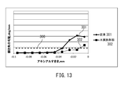
- FIG. 13 is a graph showing the relationship between the axial gap and the gradient of the inclination angle.
- FIG. 14 is a graph showing the relationship between the axial gap and the rotational torque.
- FIG. 15 is a graph showing the relationship between the axial gap and the bearing life.
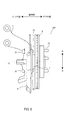
- FIG. 1 is a longitudinal sectional view of a hub unit 10 according to the embodiment.
- the vertical cross section refers to a surface obtained by cutting along a plane passing through the straight line X that is the axis of the hub unit 10.
- the cross section is a surface obtained by cutting along a plane orthogonal to the straight line X.
- the direction in which the straight line X extends is the axial direction of the hub unit 10 and the vehicle width direction of the vehicle to which the hub unit 10 is attached.
- the side closer to the vehicle body when attached to the vehicle is referred to as the inner side
- the side farther from the vehicle body is referred to as the outer side.
- the upper and lower sides of the hub unit 10 attached to the vehicle are simply referred to as the upper and lower sides.
- the vertical direction in FIG. 1 matches the vertical direction of the hub unit 10.
- the hub unit 10 includes an outer ring 1, an inner shaft 2, an inner ring 3, first and second rolling elements 41 and 42, a sealing device 5, and a cap 6.
- the outer ring 1 includes an outer ring main body 11 and an outer ring flange 12.
- the outer ring 1 has a first outer raceway surface 131 and a second outer raceway surface 132 on the inner peripheral surface.
- the outer ring main body 11 has a substantially cylindrical shape with the straight line X as an axis.
- a first outer raceway surface 131 and a second outer raceway surface 132 are provided on the inner peripheral surface of the outer ring main body 11.
- Each outer raceway surface 131, 132 is an annular surface having a straight line X as an axis.
- the first outer raceway surface 131 is disposed closer to the inner side than the second outer raceway surface 132.
- the outer ring flange 12 protrudes radially outward from the outer peripheral surface of the outer ring main body 11.
- the outer ring flange 12 has a substantially annular shape with the straight line X as an axis.
- a vehicle suspension device 7 (described later with reference to FIGS. 6 to 9) is attached to the outer ring flange 12.
- the inner shaft 2 is inserted into the outer ring 1.
- An inner ring 3 is attached to an inner side end portion of the inner shaft 2.
- the inner ring 3 has a first inner raceway surface 31 corresponding to the first outer raceway surface 131 on the outer peripheral surface.
- the inner shaft 2 has a second inner raceway surface 232 corresponding to the second outer raceway surface 132 on the outer peripheral surface.
- the inner shaft 2 includes an inner shaft main body 21 and an inner shaft flange 22.
- the inner shaft main body 21 has a substantially cylindrical shape with the straight line X as an axis.
- the inner shaft main body 21 is inserted into the outer ring main body 11.
- the inner shaft main body 21 is disposed coaxially with the outer ring main body 11.
- a second inner raceway surface 232 is provided on the outer peripheral surface of the inner shaft main body 21.
- the second inner raceway surface 232 is an annular surface having the straight line X as an axis.
- the second inner raceway surface 232 faces the second outer raceway surface 132. *
- the inner shaft flange 22 protrudes radially outward from the outer peripheral surface of the inner shaft main body 21.
- the inner shaft flange 22 has a substantially annular shape with the straight line X as an axis.
- a disc wheel, a brake disc or the like is attached to the inner shaft flange 22.
- the brake disc 9 attached to the inner shaft flange 22 will be described later with reference to FIGS. *
- the inner ring 3 has a cylindrical shape with the straight line X as an axis.
- the inner ring 3 is fixed to the inner shaft main body 21.
- An inner side end portion of the inner shaft main body 21 is caulked radially outward and is in contact with an inner side end surface of the inner ring 3. That is, the inner ring 3 is caulked and fixed to the inner shaft main body 21.
- the inner ring 3 may be fixed to the inner shaft main body 21 by press-fitting the inner shaft main body 21 into the inner ring 3.
- a first inner raceway surface 31 is provided on the outer peripheral surface of the inner ring 3.
- the first inner raceway surface 31 is an annular surface having the straight line X as an axis.
- the first inner raceway surface 31 is disposed closer to the inner side than the second inner raceway surface 232.
- the first inner raceway surface 31 faces the first outer raceway surface 131.
- a bearing space S is formed between the outer ring 1 and the inner shaft 2 and the inner ring 3.
- a plurality of first and second rolling elements 41 and 42 are disposed in the bearing space S, respectively.
- the plurality of first rolling elements 41 are arranged in an annular shape around the straight line X.
- the plurality of second rolling elements 42 are arranged in an annular shape around the straight line X.
- the first rolling element 41 is disposed closer to the inner side than the second rolling element 42.
- the first rolling element 41 is disposed in contact with the first outer raceway surface 131 and the first inner raceway surface 31.
- the second rolling element 42 is disposed in contact with the second outer raceway surface 132 and the second inner raceway surface 232.
- the contact angle of the outer side second rolling element 42 is larger than the contact angle of the inner side first rolling element 41. The contact angle between the first and second rolling elements 41 and 42 will be described later.
- the sealing device 5 has a substantially annular shape with the straight line X as an axis.
- the sealing device 5 is attached between the outer ring main body 11 and the inner shaft main body 21.
- the sealing device 5 seals the outer side end of the bearing space S.
- An end on the inner side of the bearing space S is sealed with a cap 6.
- FIG. 2 is an enlarged view of the upper portion (II-II portion) of the hub unit 10 shown in FIG.
- the first and second rolling elements 41, 42 have contact angles ⁇ 1, ⁇ 2, respectively.
- the first rolling element 41 contacts the first outer raceway surface 131 and the first inner raceway surface 31 at a contact angle ⁇ 1.
- the second rolling element 42 contacts the second outer raceway surface 132 and the second inner raceway surface 232 at a contact angle ⁇ 2.
- the hub unit 10 is a rear-arranged bearing device. That is, in the hub unit 10, the back surfaces of the first and second outer raceway surfaces 131 and 132 are close to each other.
- the contact angle ⁇ ⁇ b> 1 of the first rolling element 41 is an angle inclined toward the second rolling element 42 with respect to a plane orthogonal to the axis X of the hub unit 10.
- the contact angle ⁇ ⁇ b> 2 of the second rolling element 42 is an angle inclined toward the first rolling element 41 with respect to a plane orthogonal to the axis X of the hub unit 10.
- the contact angle ⁇ 1 of the first rolling element 41 is an angle formed by the straight line L11 and the straight line L12.
- the straight line L11 passes through the center of the first rolling element 41 in the longitudinal section of the hub unit 10 and extends perpendicularly to the axis X of the hub unit 10.
- the straight line L12 passes through the contact point between the first outer raceway surface 131 and the first rolling element 41 in the longitudinal section of the hub unit 10, and intersects the straight line L11 at the center of the first rolling element 41.
- the direction in which the straight line L12 extends is the direction of the load acting between the outer ring 1 and the inner ring 3 and the first rolling element 41.
- the contact angle ⁇ 2 of the second rolling element 42 is an angle formed by the straight line L21 and the straight line L22.
- the straight line L ⁇ b> 21 passes through the center of the second rolling element 42 in the longitudinal section of the hub unit 10 and extends perpendicularly to the axis X of the hub unit 10.
- the straight line L22 passes through the contact point between the second outer raceway surface 132 and the second rolling element 42 in the longitudinal section of the hub unit 10, and intersects the straight line L21 at the center of the second rolling element 42.
- the direction in which the straight line L22 extends is the direction of the load acting between the outer ring 1 and the inner shaft 2 and the second rolling element 42.
- FIG. 3 is a side view of the hub unit according to the embodiment.
- the outer ring main body 11 has a substantially cylindrical shape with the straight line X as an axis.
- an outer ring flange 12 extends outward in the radial direction of the hub unit 10.
- the inner shaft main body 21 also has a substantially cylindrical shape with the straight line X as an axis.
- An inner shaft flange 22 extends outward from the inner shaft body 21 in the radial direction of the hub unit 10.
- a plurality of bolts 25, 25... Are inserted into the inner shaft flange 22.
- a disc wheel and a disc brake 9 are attached to the inner shaft flange 22 by bolts 25, 25.
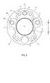
- FIG. 4 is a view of the hub unit 10 according to the embodiment as viewed from the inner side in the axial direction.
- the outer ring main body 11 has two outer ring flanges 12 and 12 attached to the upper part and two outer ring flanges 12 and 12 attached to the lower part.
- a bolt insertion hole 121 is provided in the outer ring flange 12.
- the inner shaft flange 22 has a substantially circular shape when viewed from the axial direction.
- Ribs 221 are formed at equal intervals in the circumferential direction at a position slightly inward from the outer end in the radial direction of the inner shaft flange 22.
- a plurality of bolt insertion holes 222, 222... Are formed in the rib 221.
- the rib 221 reinforces the axial thickness of the inner shaft flange 22 around the periphery where the bolt insertion hole 222 is formed.
- the bolt 25 described above is inserted into the bolt insertion hole 222.
- FIG. 5 is a view of the hub unit 10 according to the embodiment as viewed from the outer side in the axial direction.
- the inner shaft flange 22 has a substantially circular shape when viewed from the axial direction.
- the rib 221 provided on the inner shaft flange 22 is not provided on the outer side surface.
- the plurality of bolt insertion holes 222, 222... Described above are formed at equal intervals in the circumferential direction on the outer side surface.
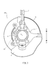
- FIG. 6 is a view of the assembly 100 in which the vehicle suspension device 7 and the brake disk 9 are assembled to the hub unit 10 according to the embodiment as viewed from the rear side of the vehicle.
- a suspension device 7 is attached to the inner side of the assembly 100.
- the suspension device 7 is fixed to the outer ring 1 by bolts 15, 15... Inserted into bolt insertion holes 121 provided in the outer ring flange 12 shown in FIG.
- a dust cover 8 is attached to the inner side of the assembly 100.
- the dust cover 8 is fixed to the outer ring 1 by bolts 15, 15... Inserted into bolt insertion holes 121 provided in the outer ring flange 12 shown in FIG.
- a brake disk 9 is attached to the outer side of the assembly 100.
- the brake disc 9 is fixed to the inner shaft 2 by bolts 25, 25... Inserted into bolt insertion holes 221 provided in the inner shaft flange 22 shown in FIGS.
- FIG. 7 is a view of an assembly 100 in which the vehicle suspension device 7 and the brake disk 9 are assembled to the hub unit 10 according to the embodiment as viewed from the inner side in the axial direction.
- the dust cover 8 covers the rear side of the vehicle (the right side of the drawing is the rear side of the vehicle), but the brake disc 9 is exposed on the front side of the vehicle.
- a brake shoe (not shown) is attached to a portion where the dust cover 8 is not provided.
- FIG. 8 is a view of an assembly 100 in which the vehicle suspension device 7 and the brake disk 9 are assembled to the hub unit 10 according to the embodiment as viewed from the outer side in the axial direction.
- the brake disc 9 is attached to the inner shaft flange 22 by bolts 25, 25... Provided at equal intervals in the circumferential direction.
- FIG. 9 is a cross-sectional view of an assembly 100 in which the vehicle suspension device 7 and the brake disk 9 are assembled to the hub unit 10 according to the embodiment, as viewed from the vehicle rear side.
- the brake disc 9 is attached so as to cover the outer side of the outer ring 1 and the inner shaft 2.
- the outer end of the brake disc 9 is attached to the inner shaft 2 by bolts 25, 25.
- the suspension device 7 is attached so as to contact the inner side surface of the outer ring flange 12.
- the dust cover 8 is also attached so as to contact the inner surface of the outer ring flange 12.
- the contact angle ⁇ 1 of the first rolling element 41 is set to be smaller than 37 °.
- the contact angle ⁇ 2 of the second rolling element 42 is set to be larger than 37 °. The reason will be described below.
- the present inventors performed a calculation based on bearing theory based on Helz contact. Specifically, the value of the contact angle ⁇ 1 of the first rolling element 41 on the inner side is fixed, the value of the contact angle ⁇ 2 of the second rolling element 42 on the outer side is changed, and the flange inclination at each value of the contact angle ⁇ 2 is changed. Angle and rotational torque were calculated. Further, the value of the contact angle ⁇ 2 of the second rolling element 42 on the outer side is fixed and the value of the contact angle ⁇ 1 of the first rolling element 41 on the inner side is changed to change the flange inclination angle and the rotation at each value of the contact angle ⁇ 1. Torque was calculated.
- the flange inclination angle is a relative inclination angle between the outer ring flange 12 and the inner shaft flange 22 and is generally used as an index indicating the rigidity of the hub unit 10.
- Table 1 shows the conditions used for the calculation.
- the number of balls of each of the first rolling element 41 and the second rolling element 42 is 11, and the pitch circle diameter (PCD), the ball diameter, and the material are the first rolling element 41 and the second rolling element 42. And is common.
- PCD pitch circle diameter
- FIG. 10 is a graph showing the relationship between each of the contact angles ⁇ 1 and ⁇ 2 and the rigidity (flange inclination angle) of the hub unit 10.
- FIG. 11 is a graph showing the relationship between each of the contact angles ⁇ 1 and ⁇ 2 and the rotational torque of the hub unit 10. 10 and 11, the flange inclination angle and the rotational torque are each indicated by a ratio [%] to the reference value.
- the rigidity of the hub unit 10 tends to improve as the contact angle ⁇ 1 of the inner first rolling element 41 decreases.
- the contact angle ⁇ 1 is less than 37 °, the change in rigidity becomes gradual. From this, it can be said that the contact angle ⁇ 1 of the first rolling element 41 is preferably smaller than 37 ° in order to ensure high rigidity stably.
- the contact angle ⁇ 1 of the first rolling element 41 may be less than 37 °, but is preferably 20 ° or more.
- the rigidity of the hub unit 10 increases as the contact angle ⁇ 2 of the second rolling element 42 on the outer side increases. Therefore, from the viewpoint of improving rigidity, the larger the contact angle ⁇ 2, the better. However, in practice, the contact angle ⁇ 2 is 70 ° or less.
- the rotational torque of the hub unit 10 decreases as the contact angle ⁇ 2 of the second rolling element 42 on the outer side increases. And when contact angle (theta) 2 exceeds 37 degrees, rotational torque becomes almost constant. From this, it can be said that the contact angle ⁇ 2 of the second rolling element 42 is preferably larger than 37 ° in order to obtain the effect of reducing the rotational torque.
- Rotational torque tends to increase as the inner contact angle ⁇ 1 decreases.
- the outer contact angle ⁇ 2 is made smaller than 37 °. This increases the rotational torque reduction effect obtained by increasing the value. Therefore, an increase in rotational torque can be suppressed.
- the hub unit 10 adjusts the contact angle between the first rolling element 41 and the second rolling element 42, thereby suppressing the increase in rotational torque and the rigidity of the hub unit 10. Can be improved.
- the hub unit 10 according to the present embodiment is adapted to optimize the rigidity, rotational torque, and life of the hub unit 10 by adjusting the axial gap, as will be described below.
- the axial gap of the hub unit 10 is determined by the degree of pressing of the inner ring 3 with respect to the inner shaft 2.
- the rolling element 41 receives pressure by the inner ring 3 depending on the degree of pressing of the inner ring 3 in the axial direction with respect to the inner shaft 2.
- the pressure received by the rolling element 41 is transmitted to the outer ring 1 through the raceway surface 131.
- the pressure received by the outer ring 1 via the raceway surface 131 is transmitted to the rolling elements 42 via the raceway surface 132.
- the pressure received by the rolling element 42 is transmitted to the inner shaft 2.
- pressure is applied to the outer ring 1, the inner shaft 2, and the rolling elements 41, 42 depending on the degree of pushing of the inner ring 3, and these are equalized to affect the rigidity or rotational torque of the entire hub unit 10.
- the axial gap becomes smaller as the degree of pushing the inner ring 3 into the inner shaft 2 becomes stronger.
- FIG. 12 is a graph showing the relationship between the axial gap and the tilt angle.
- the inclination angle is a relative inclination angle (flange inclination angle) between the outer ring flange 12 and the inner shaft flange 22.
- a graph 201 shows the relationship between the axial gap and the inclination angle of the conventional hub unit.
- a graph 202 shows the relationship between the axial gap and the inclination angle of the hub unit 10 of the present embodiment.
- the hub unit 10 of the present embodiment realizes suppression of increase in rotational torque and improvement in rigidity by adjusting the contact angles of the first rolling element 41 and the second rolling element 42. Shows what it is.
- the conventional hub unit As can be seen from the graph 201, when the axial gap becomes larger than ⁇ 0.035 mm (approaching 0), the amount of change in the inclination angle suddenly increases.
- the clearance tolerance In the conventional hub unit, when the axial gap is larger than ⁇ 0.035 mm, the amount of change in the tilt angle increases, so that the variation in product performance increases. Therefore, in the conventional hub unit, it is necessary to reduce the axial gap so that the axial gap does not become larger than ⁇ 0.035 mm even when the gap tolerance is taken into consideration. In other words, in the past, it was necessary to design the axial gap to be smaller than -0.035 mm.
- the hub unit 10 of this embodiment has a small change in the tilt angle even if the axial gap is larger than ⁇ 0.035 mm.
- the axial gap can be increased to -0.015 mm.
- An allowable line 200 in FIG. 12 indicates an allowable limit of variation in tilt angle. It can be seen that the conventional hub unit has a limit of ⁇ 0.035 mm, whereas the hub unit 10 of the present embodiment can increase the axial gap to ⁇ 0.015 mm.
- FIG. 13 is a graph showing the relationship between the axial gap and the gradient of the inclination angle.
- a graph 301 in the figure shows the gradient of the graph 201 in FIG.
- a graph 302 in the figure shows the gradient of the graph 202 in FIG.
- An allowable line 300 in FIG. 13 indicates an allowable limit as a gradient of the inclination angle.
- the region where the inclination angle is large is a region where the variation in product performance is large in consideration of tolerances. It can be seen that the conventional hub unit has a limit of ⁇ 0.035 mm, whereas the hub unit 10 of the present embodiment can increase the axial gap to ⁇ 0.015 mm.
- FIG. 14 is a graph showing the relationship between the axial gap and the rotational torque.
- This rotational torque corresponds to the contact torque when the outer ring is fixed and the inner shaft is rotated.
- the rotational torque of the hub unit 10 decreases as the axial gap increases.
- the hub unit 10 of the present embodiment can increase the axial gap as compared with the conventional case. Specifically, the axial gap can be increased to -0.015 mm. Thereby, the hub unit 10 of the present embodiment can suppress the rotational torque even if the allowable range of the axial gap is widened.
- FIG. 15 is a graph showing the relationship between the axial gap and the bearing life.
- the bearing life that is, the life of the hub unit
- the bearing life is once longer as the axial gap becomes smaller than 0. This is due in part to the increased rigidity of the hub unit due to the smaller axial gap.
- the bearing life is gradually shortened.
- the bearing life is about 40% as compared with the case where the axial gap is zero. For this reason, it is desirable that the axial gap be ⁇ 0.1 mm or more. Further, as shown in the figure, when the axial gap is larger than ⁇ 0.065 mm, the bearing life can be reduced to about 3 to 5% compared to the case where the axial gap is zero. For this reason, it is preferable that the axial gap is ⁇ 0.065 mm or more.
- the hub unit 10 of the present embodiment can increase the axial gap to ⁇ 0.015 mm by adjusting the contact angle of the rolling elements 41 and 42. Therefore, the hub unit 10 of the present embodiment preferably has an axial gap of ⁇ 0.1 mm or more and ⁇ 0.015 mm or less. In the hub unit 10 of the present embodiment, the axial gap is more preferably ⁇ 0.065 mm or more and ⁇ 0.015 mm or less. Further, from the viewpoint of reducing the rotational torque, it is preferably ⁇ 0.035 mm to ⁇ 0.015 mm.
- the contact angle ⁇ 1 of the inner first rolling element 41 is smaller than 37 °, and the contact angle ⁇ 2 of the outer second rolling element 42 is larger than 37 °.
- the hub unit 10 of the present embodiment preferably has an axial gap of ⁇ 0.1 mm or more and ⁇ 0.015 mm or less. Thereby, while satisfy
- the axial gap is more preferably ⁇ 0.065 mm or more and ⁇ 0.015 mm or less. The life of the hub unit can be maintained high, and the rigidity of the hub unit can be improved.
- Hub unit 1 Outer ring 131: First outer raceway surface 132: Second outer raceway surface 2: Inner shaft 3: Inner ring 7: Suspension device 8: Dust cover 9: Brake disk 31: First inner raceway surface 232: First 2 inner raceway surface 41: 1st rolling element 42: 2nd rolling element 100: Assembly
Landscapes
- Engineering & Computer Science (AREA)
- Mechanical Engineering (AREA)
- General Engineering & Computer Science (AREA)
- Rolling Contact Bearings (AREA)
Abstract
車両に取り付けられるハブユニットは、第1外側軌道面と、前記ハブユニットが前記車両に取り付けられた状態において前記第1外側軌道面よりも車幅方向外方側に配置される第2外側軌道面と、を内周面に有する外輪と、前記外輪の内周に前記外輪と同心状に配置され、車幅方向外方側に車輪が取り付けられる内軸と、前記内軸の車幅方向内方側に圧入されている内輪と、を備える。
Description
本開示は、ハブユニットに関し、より詳細には車両に取り付けられるハブユニットに関する。
車両用の軸受装置であるハブユニットは、内軸及び外輪を備える。内軸の車両側の端部には内輪が固定される。内軸及び内輪は、外周に軌道面を有する。外輪は、内軸及び内輪の軌道面に対応する軌道面を内周に有する。内軸及び内輪と外輪との間には、軸受空間が形成される。軸受空間には、複数列の転動体が配置される。軸受空間は、密封装置によって密封されている。
ハブユニットの剛性が高いほど、ハブユニットが搭載された車両の操舵感が向上する。ハブユニット全体の剛性には、ハブユニットの内部剛性が大きな影響を与える。
特許文献1には、車両の旋回走行時、ハブユニットにおいて、車両のインナ側の転動体に大きなラジアル荷重が負荷されると記載されている。特許文献1には、ハブユニットの回転速度や負荷荷重が大きくなると、転動体と軌道面との接触部における、摩擦による発熱量が増大するとも記載されている。そこで、特許文献1のハブユニットでは、インナ側の転動体の接触角をアウタ側の転動体の接触角よりも小さくして、インナ側の転動体のラジアル荷重の支承能力の向上とともに摩擦による発熱量の低減を図っている。
ハブユニットの内部剛性を向上させた場合、回転トルクが増大する可能性がある。特許文献1では、インナ側の転動体の接触角をアウタ側の転動体の接触角よりも小さくすることにより、回転トルク(軸受トルク)から換算される発熱量が少なくなることが開示されている。しかしながら、特許文献1のハブユニットには、回転トルクの増大抑制及び剛性の向上の両立という点で、より改善する余地がある。
本開示は、回転トルクの増大を抑制しつつ、剛性を向上させることができるハブユニットが提供される。また、本開示は、軸受寿命を向上させることができるハブユニットが提供される。
本開示に係るハブユニットは、車両に取り付けられる。ハブユニットは、外輪と、内軸と、内輪と、複数の第1転動体と、複数の第2転動体とを備える。外輪は、第1外側軌道面と、第2外側軌道面とを内周面に有する。第2外側軌道面は、ハブユニットが車両に取り付けられた状態において第1外側軌道面よりも車幅方向外方側に配置される。内軸は、前記外輪の内周に前記外輪と同心状に配置され、車幅方向外方側に車輪が取り付けられる。内輪は、前記内軸の車幅方向内方側に圧入される。内輪は、第1内側軌道面を外周面に有する。第1内側軌道面は、第1外側軌道面に対応する。内軸は、第2内側軌道面を外周面に有する。第2内側軌道面は、第2外側軌道面に対応する。複数の第1転動体は、軸受空間内に配置される。複数の第1転動体は、37°よりも小さい接触角で第1外側軌道面及び第1内側軌道面に接触する。軸受空間は、外輪と内輪が装着された内軸との間に形成される。複数の第2転動体は、軸受空間内に配置される。複数の第2転動体は、37°よりも大きい接触角で第2外側軌道面及び第2内側軌道面に接触する。
ハブユニットでは、車幅方向内方に配置される第1転動体の接触角が37°より小さく、車幅方向外方に配置される第2転動体の接触角が37°よりも大きい。詳しくは後述するが、この構成によれば、ハブユニットにおいて、回転トルクの増大を抑制しつつ、剛性を向上させることができる。
本実施の形態のハブユニットは、内軸に対する内輪の押し込み度合いによって決まるアキシアル隙間は、-0.1mm以上で-0.015mm以下である。
ハブユニットの寿命について要求を満たすとともに、ハブユニットの剛性を向上させることができる。
本実施の形態のハブユニットは、内軸に対する内輪の押し込み度合いによって決まるアキシアル隙間は、-0.065mm以上で-0.015mm以下である。
ハブユニットの寿命を高く維持できるとともに、ハブユニットの剛性を向上させることができる。
本開示に係るハブユニットによれば、回転トルクの増大を抑制しつつ、剛性を向上させることができる。
以下、実施形態について図面を参照しつつ説明する。図中同一及び相当する構成については同一の符号を付し、同じ説明を繰り返さない。説明の便宜上、各図において、構成を簡略化又は模式化して示したり、一部の構成を省略して示したりする場合がある。
[ハブユニットの構造]
図1は、実施形態に係るハブユニット10の縦断面図である。縦断面とは、ハブユニット10の軸心である直線Xを通る平面で切断したときの面をいう。横断面は、直線Xに直交する平面で切断したときの面である。直線Xが延びる方向は、ハブユニット10の軸方向、及びハブユニット10が取り付けられる車両の車幅方向である。以下、ハブユニット10の軸方向において、車両に取り付けたときに車体に近い方をインナ側、車体から遠い方をアウタ側と称する。車両に取り付けた状態のハブユニット10における上下を、単に上下という。図1における上下方向は、ハブユニット10の上下方向と一致している。
図1は、実施形態に係るハブユニット10の縦断面図である。縦断面とは、ハブユニット10の軸心である直線Xを通る平面で切断したときの面をいう。横断面は、直線Xに直交する平面で切断したときの面である。直線Xが延びる方向は、ハブユニット10の軸方向、及びハブユニット10が取り付けられる車両の車幅方向である。以下、ハブユニット10の軸方向において、車両に取り付けたときに車体に近い方をインナ側、車体から遠い方をアウタ側と称する。車両に取り付けた状態のハブユニット10における上下を、単に上下という。図1における上下方向は、ハブユニット10の上下方向と一致している。
図1に示すように、ハブユニット10は、外輪1と、内軸2と、内輪3と、第1及び第2転動体41,42と、密封装置5と、キャップ6とを備える。
外輪1は、外輪本体11と、外輪フランジ12とを備える。外輪1は、第1外側軌道面131と、第2外側軌道面132とを内周面に有する。
外輪本体11は、直線Xを軸心とする概略円筒状をなす。外輪本体11の内周面には、第1外側軌道面131及び第2外側軌道面132が設けられている。各外側軌道面131,132は、それぞれ、直線Xを軸心とする環状面である。第1外側軌道面131は、第2外側軌道面132よりもインナ側に配置されている。
外輪フランジ12は、外輪本体11の外周面から径方向外方に突出する。外輪フランジ12は、直線Xを軸心とする概略環状をなす。外輪フランジ12には、車両の懸架装置7(後で図6~図9を用いて説明する。)が取り付けられる。
内軸2は、外輪1に挿入される。内軸2のインナ側の端部には、内輪3が装着される。内輪3は、第1外側軌道面131に対応する第1内側軌道面31を外周面に有する。内軸2は、第2外側軌道面132に対応する第2内側軌道面232を外周面に有する。
内軸2は、内軸本体21と、内軸フランジ22とを含む。内軸本体21は、直線Xを軸心とする概略円柱状をなす。内軸本体21は、外輪本体11に挿入される。内軸本体21は、外輪本体11と同軸に配置される。内軸本体21の外周面には、第2内側軌道面232が設けられている。第2内側軌道面232は、直線Xを軸心とする環状面である。第2内側軌道面232は、第2外側軌道面132と対向する。
内軸フランジ22は、内軸本体21の外周面から径方向外方に突出する。内軸フランジ22は、直線Xを軸心とする概略環状をなす。内軸フランジ22には、ディスクホイールやブレーキディスク等が取り付けられる。内軸フランジ22に取り付けられたブレーキディスク9については図6~図9を用いて後で説明する。
内輪3は、直線Xを軸心とする筒状をなす。内輪3は、内軸本体21に固定されている。内軸本体21のインナ側の端部は、径方向外方にかしめられ、内輪3のインナ側の端面に接触している。すなわち、内輪3は、内軸本体21にかしめ固定されている。ただし、内輪3に対して内軸本体21を圧入することにより、内輪3が内軸本体21に固定されていてもよい。
内輪3の外周面には、第1内側軌道面31が設けられている。第1内側軌道面31は、直線Xを軸心とする環状面である。第1内側軌道面31は、第2内側軌道面232よりもインナ側に配置されている。第1内側軌道面31は、第1外側軌道面131と対向する。
外輪1と内軸2及び内輪3との間には、軸受空間Sが形成される。軸受空間S内には、それぞれ複数の第1及び第2転動体41,42が配置されている。複数の第1転動体41は、直線Xを中心として円環状に配列される。複数の第2転動体42は、直線Xを中心として円環状に配列される。第1転動体41は、第2転動体42よりもインナ側に配置されている。
第1転動体41は、第1外側軌道面131及び第1内側軌道面31に接触して配置される。第2転動体42は、第2外側軌道面132及び第2内側軌道面232に接触して配置される。アウタ側の第2転動体42の接触角は、インナ側の第1転動体41の接触角よりも大きい。第1及び第2転動体41,42の接触角については後述する。
密封装置5は、直線Xを軸心とする概略環状をなす。密封装置5は、外輪本体11と内軸本体21との間に取り付けられる。密封装置5は、軸受空間Sのアウタ側の端部を封鎖する。軸受空間Sのインナ側の端部は、キャップ6によって封鎖されている。
図2は、図1に示すハブユニット10の上部(II-II部分)の拡大図である。図2に示すように、第1及び第2転動体41,42は、それぞれ、接触角θ1,θ2を有する。第1転動体41は、第1外側軌道面131及び第1内側軌道面31に接触角θ1で接触する。第2転動体42は、第2外側軌道面132及び第2内側軌道面232に接触角θ2で接触する。
ハブユニット10は、背面配列の軸受装置である。すなわち、ハブユニット10では、第1及び第2外側軌道面131,132の背面同士が互いに近接する。第1転動体41の接触角θ1は、ハブユニット10の軸心Xに直交する平面に対して第2転動体42側に傾いた角である。第2転動体42の接触角θ2は、ハブユニット10の軸心Xに直交する平面に対して第1転動体41側に傾いた角である。
ハブユニット10の縦断面において、第1転動体41の接触角θ1は、直線L11と直線L12とがなす角である。直線L11は、ハブユニット10の縦断面において、第1転動体41の中心を通り、ハブユニット10の軸心Xに垂直に延びる。直線L12は、ハブユニット10の縦断面において、第1外側軌道面131と第1転動体41との接触点を通り、第1転動体41の中心で直線L11と交差する。直線L12が延びる方向は、外輪1及び内輪3と第1転動体41との間に作用する荷重の方向である。
ハブユニット10の縦断面において、第2転動体42の接触角θ2は、直線L21と直線L22とがなす角である。直線L21は、ハブユニット10の縦断面において、第2転動体42の中心を通り、ハブユニット10の軸心Xに垂直に延びる。直線L22は、ハブユニット10の縦断面において、第2外側軌道面132と第2転動体42との接触点を通り、第2転動体42の中心で直線L21と交差する。直線L22が延びる方向は、外輪1及び内軸2と第2転動体42との間に作用する荷重の方向である。
図3は、実施形態に係るハブユニットの側面図である。図に示すように、外輪本体11は、直線Xを軸心とする概略円筒状をなす。外輪本体11のインナ側には、ハブユニット10の径方向で外方に向って外輪フランジ12が延びている。また、内軸本体21も、直線Xを軸心とする概略円筒状をなす。内軸本体21には、ハブユニット10の径方向で外方に向って内軸フランジ22が延びている。内軸フランジ22には複数のボルト25,25・・・が挿入されている。内軸フランジ22には、ボルト25,25・・・によって、ディスクホイールやディスクブレーキ9が取り付けられる。
図4は、実施形態に係るハブユニット10を軸方向についてインナ側から見た図である。図に示すように、外輪本体11には、上部に2つの外輪フランジ12・12が取り付けられ、下部に2つの外輪フランジ12・12が取り付けられている。外輪フランジ12には、ボルト挿入孔121が設けられている。
図4に示すように、内軸フランジ22は、軸方向から見て概略円形状である。内軸フランジ22の径方向で外端からやや内側に入ったところには、リブ221が周方向に等間隔で形成されている。リブ221には、複数のボルト挿入孔222,222・・・が形成されている。リブ221により、ボルト挿入孔222が形成されている周辺については、内軸フランジ22の軸方向の厚みが補強されている。ボルト挿入孔222には、前述したボルト25が挿入される。
図5は、実施形態に係るハブユニット10を軸方向についてアウタ側から見た図である。図5にも示すように、内軸フランジ22は、軸方向から見て概略円形状である。上述した内軸フランジ22に設けられたリブ221は、アウタ側の面には設けられていない。アウタ側の面には前述した複数のボルト挿入孔222,222・・・が周方向に等間隔で形成されている。
図6は、実施形態に係るハブユニット10に車両の懸架装置7やブレーキディスク9を組み付けた組立品100を車両後方側から見た図である。図に示すように、組立品100のインナ側には、懸架装置7が取り付けられている。懸架装置7は、図4で示した外輪フランジ12に設けられたボルト挿入孔121に挿入されたボルト15,15・・・によって、外輪1に固定されている。
図6に示すように、組立品100のインナ側には、ダストカバー8が取り付けられている。ダストカバー8は、図4で示した外輪フランジ12に設けられたボルト挿入孔121に挿入されたボルト15,15・・・によって、外輪1に固定されている。
図6に示すように、組立品100のアウタ側には、ブレーキディスク9が取り付けられている。ブレーキディスク9は、図4および図5で示した内軸フランジ22に設けられたボルト挿入孔221に挿入されたボルト25,25・・・によって、内軸2に固定されている。
図7は、実施形態に係るハブユニット10に車両の懸架装置7やブレーキディスク9を組み付けた組立品100を軸方向のインナ側から見た図である。図に示すように、ダストカバー8は、車両の後方側(図面の右側が車両後方側である)を覆っているが、車両の前方側はブレーキディスク9が露出している。このダストカバー8の設けられていない部分には、図示せぬブレーキシューが取り付けられる。
図8は、実施形態に係るハブユニット10に車両の懸架装置7やブレーキディスク9を組み付けた組立品100を軸方向のアウタ側から見た図である。ブレーキディスク9は、周方向で等間隔に設けられたボルト25,25・・・によって内軸フランジ22に取り付けられている。
図9は、実施形態に係るハブユニット10に車両の懸架装置7やブレーキディスク9を組み付けた組立品100を車両後方側から見た断面図である。図に示すように、ブレーキディスク9は、外輪1および内軸2のアウタ側を覆うようにして取り付けられている。ブレーキディスク9のアウタ側の端部がボルト25,25・・・によって、内軸2に取り付けられている。懸架装置7は、外輪フランジ12のインナ側の面に接触するようにして取り付けられている。ダストカバー8も、外輪フランジ12のインナ側の面に接触するようにして取り付けられている。
再び、図2を参照する。第1転動体41の接触角θ1は、37°よりも小さくなるように設定される。第2転動体42の接触角θ2は、37°よりも大きくなるように設定される。以下、その理由について説明する。
接触角θ1,θ2の最適な範囲を決定するため、本発明者等は、Helz接触を基礎とした軸受理論による計算を実施した。具体的には、インナ側の第1転動体41の接触角θ1の値を固定してアウタ側の第2転動体42の接触角θ2の値を変化させ、接触角θ2の各値におけるフランジ傾き角及び回転トルクを計算した。また、アウタ側の第2転動体42の接触角θ2の値を固定してインナ側の第1転動体41の接触角θ1の値を変化させ、接触角θ1の各値におけるフランジ傾き角及び回転トルクを計算した。フランジ傾き角は、外輪フランジ12と内軸フランジ22との相対傾き角であり、一般に、ハブユニット10の剛性を示す指標として用いられる。
計算に用いた条件を表1に示す。表1において、第1転動体41及び第2転動体42の玉数はそれぞれ11個であり、ピッチ円直径(PCD)、玉径、及び素材は、第1転動体41と第2転動体42とで共通である。

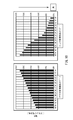
図10は、接触角θ1,θ2の各々とハブユニット10の剛性(フランジ傾き角)との関係を示すグラフである。図11は、接触角θ1,θ2の各々とハブユニット10の回転トルクとの関係を示すグラフである。図10及び図11において、フランジ傾き角及び回転トルクは、それぞれ、基準値に対する比率[%]で示されている。
図10に示すように、ハブユニット10の剛性は、インナ側の第1転動体41の接触角θ1が小さくなるにつれて向上する傾向にある。そして、接触角θ1が37°未満になると、剛性の変化は緩やかになる。このことから、高い剛性を安定して確保するためには、第1転動体41の接触角θ1は37°よりも小さいことが好ましいといえる。第1転動体41の接触角θ1は、37°未満であればよいが、好ましくは20°以上である。
ハブユニット10の剛性は、アウタ側の第2転動体42の接触角θ2が大きくなるほど高くなる。よって、剛性の向上という観点からは、接触角θ2は大きいほどよい。ただし、現実的には、接触角θ2は70°以下である。
図11に示すように、ハブユニット10の回転トルクは、アウタ側の第2転動体42の接触角θ2が大きくなるにつれて低減する。そして、接触角θ2が37°を超えた時点で、回転トルクはほとんど一定になる。このことから、回転トルクの低減効果を得るためには、第2転動体42の接触角θ2は37°よりも大きいことが好ましいといえる。
回転トルクは、インナ側の接触角θ1が小さくなるほど増大する傾向にある。上述したように、良好な剛性を得るためには接触角θ1を37°よりも小さくする必要があるが、これにより回転トルクが大きくなったとしても、アウタ側の接触角θ2を37°よりも大きくすることで得られる回転トルクの低減効果と相殺される。よって、回転トルクの増大を抑制することができる。
以上説明したように、本実施形態に係るハブユニット10は、第1転動体41および第2転動体42の接触角を調整することで、回転トルクの増大を抑制しつつ、ハブユニット10の剛性を向上させることができる。本実施の形態に係るハブユニット10は、さらに次に説明するように、アキシアル隙間を調整することで、ハブユニット10の剛性、回転トルクおよび寿命の最適化を図るようにしている。
ハブユニット10のアキシアル隙間は、内輪3の内軸2に対する押し込み度合いによって決定される。内輪3の内軸2に対する軸方向への押し込み度合いにより、内輪3によって転動体41が圧力を受ける。転動体41が受ける圧力は、軌道面131を介して外輪1に伝達される。軌道面131を介して外輪1が受けた圧力は、軌道面132を介して転動体42に伝達される。転動体42が受けた圧力は内軸2に伝達される。このように内輪3の押し込み度合いにより、外輪1、内軸2、転動体41・42に圧力が加わり、これらが均等化されてハブユニット10全体の剛性あるいは回転トルクに影響を与える。内輪3の内軸2に対する押し込み度合いが強くなればなるほどアキシアル隙間は小さくなる。
図12は、アキシアル隙間と傾き角との関係を示すグラフである。傾き角は、外輪フランジ12と内軸フランジ22との相対傾き角(フランジ傾き角)である。図中、グラフ201は、従来のハブユニットのアキシアル隙間と傾き角との関係を示す。図中、グラフ202は、本実施形態のハブユニット10のアキシアル隙間と傾き角との関係を示す。本実施の形態のハブユニット10とは、上述したように、第1転動体41および第2転動体42の接触角を調整することにより、回転トルクの増大の抑制と、剛性の向上を実現しているものを示している。
従来のハブユニットについては、グラフ201を見れば分かるように、アキシアル隙間が-0.035mmより大きくなると(0に近づくと)、急激に傾き角の変化量が大きくなっている。ここで、ハブユニット10を組み立てるときには、隙間公差を考慮する必要がある。従来のハブユニットにおいては、アキシアル隙間が-0.035mmより大きくなると、傾き角の変化量が大きくなるため製品の性能のばらつきが大きくなる。このため、従来のハブユニットにおいては、隙間公差を考慮しても、アキシアル隙間が-0.035mmより大きくならないよう、アキシアル隙間を小さくする必要があった。つまり、従来においては、アキシアル隙間を-0.035mmより隙間公差分小さく設計する必要があった。
これに対して本実施形態のハブユニット10は、グラフ202を見れば分かるように、アキシアル隙間が-0.035mmより大きくなったとしても傾き角の変化量が小さい。本実施形態のハブユニット10においては、アキシアル隙間を-0.015mmまで大きくすることが可能である。図12における許容ライン200は、傾き角のばらつきの許容できる限界を示している。従来のハブユニットについては、-0.035mmが限界であるのに対して、本実施形態のハブユニット10は、-0.015mmまでアキシアル隙間を大きくできることが分かる。
図13は、アキシアル隙間と傾き角の勾配との関係を示すグラフである。図中のグラフ301は、図12におけるグラフ201の勾配を示している。図中のグラフ302は、図12におけるグラフ202の勾配を示している。図13における許容ライン300は、傾き角の勾配として許容できる限界を示している。傾き角の勾配が大きい領域は、公差を考慮すると製品の性能のばらつきが大きくなる領域である。従来のハブユニットについては、-0.035mmが限界であるのに対して、本実施形態のハブユニット10は、-0.015mmまでアキシアル隙間を大きくできることが分かる。
図14は、アキシアル隙間と回転トルクとの関係を示すグラフである。本回転トルクは外輪を固定して内軸を回転させたときの接触トルクに該当する。図から分かるように、アキシアル隙間が大きくなるほど、ハブユニット10の回転トルクが小さくなることが分かる。上述したように、本実施形態のハブユニット10は、従来に比べてアキシアル隙間を大きくすることができる。具体的には、アキシアル隙間を-0.015mmまで大きくすることができる。これにより、本実施形態のハブユニット10はアキシアル隙間の許容範囲を広げても回転トルクも抑制することが可能である。
図15は、アキシアル隙間と軸受寿命との関係を示すグラフである。アキシアル隙間が0(軸受寿命100%)の状態に比べると、アキシアル隙間が0より小さくなるにつれて、一旦、軸受寿命(つまりハブユニットの寿命)が長くなる。これは、アキシアル隙間が小さくなることにより、ハブユニットの剛性が高くなることが一要因である。しかし、さらにアキシアル隙間が小さくなると、次第に軸受寿命(つまりハブユニットの寿命)が短くなっていく。
図で示すように、アキシアル隙間が-0.1mmまで小さくなると、アキシアル隙間が0の場合と比べて軸受寿命が40%程度となる。このため、アキシアル隙間は、-0.1mm以上とすることが望ましい。また、図で示すように、アキシアル隙間が-0.065mmより大きくなると、軸受寿命は、アキシアル隙間が0の場合と比べても寿命の低下を3~5%程度に抑えることができる。このため、好ましくは、アキシアル隙間は、-0.065mm以上とすることが望ましい。
上述したように、本実施形態のハブユニット10は、転動体41・42の接触角を調整することで、アキシアル隙間を-0.015mmまで大きくすることが可能となった。したがって、本実施形態のハブユニット10は、好ましくは、アキシアル隙間が-0.1mm以上で-0.015mm以下である。本実施形態のハブユニット10は、さらに好ましくは、アキシアル隙間が-0.065mm以上で-0.015mm以下である。さらに、回転トルクを小さくする観点より、好ましくは-0.035mm~-0.015mmである。
[効果]
本実施形態に係るハブユニット10では、インナ側の第1転動体41の接触角θ1が37°よりも小さく、アウタ側の第2転動体42の接触角θ2が37°よりも大きい。このようにすることで、上述した通り、回転トルクの増大を抑制しつつ、ハブユニット10の剛性を向上させることができる。
本実施形態に係るハブユニット10では、インナ側の第1転動体41の接触角θ1が37°よりも小さく、アウタ側の第2転動体42の接触角θ2が37°よりも大きい。このようにすることで、上述した通り、回転トルクの増大を抑制しつつ、ハブユニット10の剛性を向上させることができる。
本実施形態のハブユニット10は、好ましくは、アキシアル隙間が-0.1mm以上で-0.015mm以下である。これにより、ハブユニットの寿命について要求を満たすとともに、ハブユニットの剛性を向上させることができる。本実施形態のハブユニット10は、さらに好ましくは、アキシアル隙間が-0.065mm以上で-0.015mm以下である。ハブユニットの寿命を高く維持できるとともに、ハブユニットの剛性を向上させることができる。
以上、実施形態について説明したが、本開示は上記実施形態に限定されるものではなく、その趣旨を逸脱しない限りにおいて種々の変更が可能である。
10:ハブユニット
1:外輪
131:第1外側軌道面
132:第2外側軌道面
2:内軸
3:内輪
7:懸架装置
8:ダストカバー
9:ブレーキディスク
31:第1内側軌道面
232:第2内側軌道面
41:第1転動体
42:第2転動体
100:組立品
1:外輪
131:第1外側軌道面
132:第2外側軌道面
2:内軸
3:内輪
7:懸架装置
8:ダストカバー
9:ブレーキディスク
31:第1内側軌道面
232:第2内側軌道面
41:第1転動体
42:第2転動体
100:組立品
Claims (3)
- 車両に取り付けられるハブユニットであって、
第1外側軌道面と、前記ハブユニットが前記車両に取り付けられた状態において前記第1外側軌道面よりも車幅方向外方側に配置される第2外側軌道面と、を内周面に有する外輪と、
前記外輪の内周に前記外輪と同心状に配置され、車幅方向外方側に車輪が取り付けられる内軸と、
前記内軸の車幅方向内方側に圧入されている内輪と、
を備え、
前記内輪は、前記第1外側軌道面に対応する第1内側軌道面を外周面に有し、
前記内軸は、前記第2外側軌道面に対応する第2内側軌道面を外周面に有しており、
前記ハブユニットは、さらに、
前記外輪と前記内輪が装着された前記内軸との間に形成される軸受空間内に配置され、37°よりも小さい接触角で前記第1外側軌道面及び前記第1内側軌道面に接触する複数の第1転動体と、
前記軸受空間内に配置され、37°よりも大きい接触角で前記第2外側軌道面及び前記第2内側軌道面に接触する複数の第2転動体と、を備える、ハブユニット。 - 請求項1に記載のハブユニットにおいて、
前記内軸に対する前記内輪の押し込み度合いによって決まるアキシアル隙間は、-0.1mm以上で-0.015mm以下であるハブユニット。 - 請求項1に記載のハブユニットにおいて、
前記内軸に対する前記内輪の押し込み度合いによって決まるアキシアル隙間は、-0.065mm以上で-0.015mm以下であるハブユニット。
Priority Applications (4)
| Application Number | Priority Date | Filing Date | Title |
|---|---|---|---|
| DE112017004607.6T DE112017004607T8 (de) | 2016-09-13 | 2017-09-12 | Nabeneinheit |
| CN201780055587.8A CN109690096A (zh) | 2016-09-13 | 2017-09-12 | 毂单元 |
| KR1020197006851A KR102233055B1 (ko) | 2016-09-13 | 2017-09-12 | 허브 유닛 |
| US16/323,052 US10780735B2 (en) | 2016-09-13 | 2017-09-12 | Hub unit |
Applications Claiming Priority (4)
| Application Number | Priority Date | Filing Date | Title |
|---|---|---|---|
| JP2016178173 | 2016-09-13 | ||
| JP2016-178173 | 2016-09-13 | ||
| JP2017-158168 | 2017-08-18 | ||
| JP2017158168A JP2018044670A (ja) | 2016-09-13 | 2017-08-18 | ハブユニット |
Publications (1)
| Publication Number | Publication Date |
|---|---|
| WO2018051986A1 true WO2018051986A1 (ja) | 2018-03-22 |
Family
ID=61619469
Family Applications (1)
| Application Number | Title | Priority Date | Filing Date |
|---|---|---|---|
| PCT/JP2017/032918 Ceased WO2018051986A1 (ja) | 2016-09-13 | 2017-09-12 | ハブユニット |
Country Status (1)
| Country | Link |
|---|---|
| WO (1) | WO2018051986A1 (ja) |
Citations (2)
| Publication number | Priority date | Publication date | Assignee | Title |
|---|---|---|---|---|
| JP2004076892A (ja) * | 2002-08-21 | 2004-03-11 | Nsk Ltd | 車輪用複列アンギュラ型玉軸受 |
| JP2006022850A (ja) * | 2004-07-06 | 2006-01-26 | Ntn Corp | 予圧可変機構付車輪用軸受装置 |
-
2017
- 2017-09-12 WO PCT/JP2017/032918 patent/WO2018051986A1/ja not_active Ceased
Patent Citations (2)
| Publication number | Priority date | Publication date | Assignee | Title |
|---|---|---|---|---|
| JP2004076892A (ja) * | 2002-08-21 | 2004-03-11 | Nsk Ltd | 車輪用複列アンギュラ型玉軸受 |
| JP2006022850A (ja) * | 2004-07-06 | 2006-01-26 | Ntn Corp | 予圧可変機構付車輪用軸受装置 |
Similar Documents
| Publication | Publication Date | Title |
|---|---|---|
| US7648283B2 (en) | Bearing apparatus for a wheel of vehicle | |
| JP5561151B2 (ja) | 車輪駆動用軸受ユニット | |
| US10316893B2 (en) | Wheel bearing apparatus | |
| JP7151533B2 (ja) | ハブユニット軸受 | |
| CN108569083A (zh) | 用于机动车的车轮支承组件 | |
| JP2013082293A (ja) | 駆動車輪用軸受装置 | |
| JP7119992B2 (ja) | ハブユニット軸受 | |
| JP2008100632A (ja) | 車輪用軸受装置 | |
| JP2011207298A (ja) | 車輪用軸受装置の内輪 | |
| JP2018044670A (ja) | ハブユニット | |
| JP2000177301A (ja) | ホイール用ハブユニット軸受 | |
| US12485702B2 (en) | Drive axle assembly | |
| JP6834141B2 (ja) | ハブユニット | |
| US12013038B2 (en) | Sealing device | |
| US20200031164A1 (en) | Vehicular bearing device | |
| JP5087901B2 (ja) | 車輪用転がり軸受装置 | |
| US12497996B2 (en) | Wheel hub assembly having low friction and high performance | |
| JP4772637B2 (ja) | 車輪軸受装置 | |
| JP5891720B2 (ja) | ハブユニット軸受 | |
| JP2011111010A (ja) | 車輪用軸受装置 | |
| JP7441609B2 (ja) | 車輪用軸受装置 | |
| KR20200089192A (ko) | 차량용 휠베어링 | |
| US20220324255A1 (en) | Wheel hub assembly with optimized raceways | |
| JP2005289147A (ja) | 車輪用軸受装置 | |
| JP6226006B2 (ja) | 車両用ハブユニット |
Legal Events
| Date | Code | Title | Description |
|---|---|---|---|
| 121 | Ep: the epo has been informed by wipo that ep was designated in this application |
Ref document number: 17850887 Country of ref document: EP Kind code of ref document: A1 |
|
| ENP | Entry into the national phase |
Ref document number: 20197006851 Country of ref document: KR Kind code of ref document: A |
|
| 122 | Ep: pct application non-entry in european phase |
Ref document number: 17850887 Country of ref document: EP Kind code of ref document: A1 |