WO2018051786A1 - 熱交換器 - Google Patents
熱交換器 Download PDFInfo
- Publication number
- WO2018051786A1 WO2018051786A1 PCT/JP2017/031082 JP2017031082W WO2018051786A1 WO 2018051786 A1 WO2018051786 A1 WO 2018051786A1 JP 2017031082 W JP2017031082 W JP 2017031082W WO 2018051786 A1 WO2018051786 A1 WO 2018051786A1
- Authority
- WO
- WIPO (PCT)
- Prior art keywords
- refrigerant
- passage
- outlet
- cooling water
- heat transfer
- Prior art date
- Legal status (The legal status is an assumption and is not a legal conclusion. Google has not performed a legal analysis and makes no representation as to the accuracy of the status listed.)
- Ceased
Links
Images


Classifications
-
- B—PERFORMING OPERATIONS; TRANSPORTING
- B60—VEHICLES IN GENERAL
- B60H—ARRANGEMENTS OF HEATING, COOLING, VENTILATING OR OTHER AIR-TREATING DEVICES SPECIALLY ADAPTED FOR PASSENGER OR GOODS SPACES OF VEHICLES
- B60H1/00—Heating, cooling or ventilating [HVAC] devices
- B60H1/32—Cooling devices
-
- F—MECHANICAL ENGINEERING; LIGHTING; HEATING; WEAPONS; BLASTING
- F25—REFRIGERATION OR COOLING; COMBINED HEATING AND REFRIGERATION SYSTEMS; HEAT PUMP SYSTEMS; MANUFACTURE OR STORAGE OF ICE; LIQUEFACTION SOLIDIFICATION OF GASES
- F25B—REFRIGERATION MACHINES, PLANTS OR SYSTEMS; COMBINED HEATING AND REFRIGERATION SYSTEMS; HEAT PUMP SYSTEMS
- F25B39/00—Evaporators; Condensers
- F25B39/04—Condensers
-
- F—MECHANICAL ENGINEERING; LIGHTING; HEATING; WEAPONS; BLASTING
- F28—HEAT EXCHANGE IN GENERAL
- F28D—HEAT-EXCHANGE APPARATUS, NOT PROVIDED FOR IN ANOTHER SUBCLASS, IN WHICH THE HEAT-EXCHANGE MEDIA DO NOT COME INTO DIRECT CONTACT
- F28D9/00—Heat-exchange apparatus having stationary plate-like or laminated conduit assemblies for both heat-exchange media, the media being in contact with different sides of a conduit wall
- F28D9/02—Heat-exchange apparatus having stationary plate-like or laminated conduit assemblies for both heat-exchange media, the media being in contact with different sides of a conduit wall the heat-exchange media travelling at an angle to one another
-
- F—MECHANICAL ENGINEERING; LIGHTING; HEATING; WEAPONS; BLASTING
- F28—HEAT EXCHANGE IN GENERAL
- F28F—DETAILS OF HEAT-EXCHANGE AND HEAT-TRANSFER APPARATUS, OF GENERAL APPLICATION
- F28F3/00—Plate-like or laminated elements; Assemblies of plate-like or laminated elements
- F28F3/02—Elements or assemblies thereof with means for increasing heat-transfer area, e.g. with fins, with recesses, with corrugations
- F28F3/04—Elements or assemblies thereof with means for increasing heat-transfer area, e.g. with fins, with recesses, with corrugations the means being integral with the element
-
- F—MECHANICAL ENGINEERING; LIGHTING; HEATING; WEAPONS; BLASTING
- F28—HEAT EXCHANGE IN GENERAL
- F28F—DETAILS OF HEAT-EXCHANGE AND HEAT-TRANSFER APPARATUS, OF GENERAL APPLICATION
- F28F3/00—Plate-like or laminated elements; Assemblies of plate-like or laminated elements
- F28F3/08—Elements constructed for building-up into stacks, e.g. capable of being taken apart for cleaning
-
- F—MECHANICAL ENGINEERING; LIGHTING; HEATING; WEAPONS; BLASTING
- F28—HEAT EXCHANGE IN GENERAL
- F28F—DETAILS OF HEAT-EXCHANGE AND HEAT-TRANSFER APPARATUS, OF GENERAL APPLICATION
- F28F9/00—Casings; Header boxes; Auxiliary supports for elements; Auxiliary members within casings
- F28F9/22—Arrangements for directing heat-exchange media into successive compartments, e.g. arrangements of guide plates
Definitions
- the present invention relates to a heat exchanger in which heat transfer plates are stacked.
- a water-cooled condenser which is a heat exchanger, has a refrigerant passage through which the refrigerant passes and a cooling water passage through which the cooling water passes in the heat exchanger. The heat is exchanged and the refrigerant is cooled by the cooling water.
- Such a water-cooled condenser is configured by laminating a large number of heat transfer plates, and a refrigerant passage and a cooling water passage are respectively formed between adjacent heat transfer plates.
- the refrigerant passage and the cooling water passage are alternately formed with the heat transfer plates as partitions, and the refrigerant and the cooling water exchange heat via the heat transfer plate.
- a cooling water inlet, a cooling water outlet, and a refrigerant inlet are formed on the heat transfer plate disposed at one end in the stacking direction.
- the heat transfer plate disposed at the other end in the stacking direction is formed with a refrigerant outlet and a refrigerant inlet and a refrigerant outlet for the subcooling unit, in addition to the refrigerant outlet.
- the inlets / outlets (four in total when there is no subcooling portion) of the cooling water and the refrigerant are provided separately for the two heat transfer plates disposed at both ends in the lamination direction There is.
- the cooling water inlet and the cooling water outlet are at the corners of the diagonal of the square heat transfer plate (corners It is usually formed in.
- the refrigerant inlet and the refrigerant outlet are also preferably formed at diagonal corner portions of the square heat transfer plate from the viewpoint of improving heat exchange.
- restriction is required on the installation position of the refrigerant outlet from the viewpoint of component installation of the refrigeration cycle, effective use of dead space, etc.
- the degree of freedom of the installation position of the refrigerant outlet may be limited.
- an object of this invention is to provide the heat exchanger with a high freedom degree of the installation position of a refrigerant
- a cooling water passage through which cooling water flows and a refrigerant passage through which refrigerant of the refrigeration cycle flows are respectively formed between two adjacent heat transfer plates in the stacking direction, and the stacking direction
- the cooling water flow inlet externally flows the cooling water into the cooling water passage and the cooling water flow outlet flowing the cooling water to the outside from the cooling water passage
- Heat exchanger provided with a refrigerant outlet and a refrigerant outlet for discharging the refrigerant to the outside from the refrigerant passage, the heat transfer plate disposed at one end of the stacking direction, the coolant inlet and the coolant outlet, and the refrigerant flow
- a heat is characterized in that a refrigerant return passage for returning the refrigerant to the refrigerant outlet is formed inside the heat transfer plate provided with both the inlet and the refrigerant outlet and arranged at one end in the stacking direction.
- FIG. 1 shows a first embodiment of the present invention, and is a configuration diagram of a vehicle air conditioner.
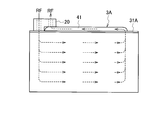
- FIG. 2 shows a first embodiment of the present invention and is a schematic perspective view of a water-cooled condenser.
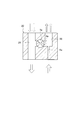
- Fig.3 (a) is principal part sectional drawing of the water-cooled condenser which shows the flow of a cooling water based on 1st Embodiment of this invention
- FIG.3 (b) is a refrigerant based on 1st Embodiment of this invention. It is principal part sectional drawing of the water-cooled condenser which shows a flow.
- FIG. 4 shows a first embodiment of the present invention, and is a conceptual view showing the flow of the refrigerant in the entire water-cooled condenser.
- FIG.5 (a) is a schematic sectional drawing of the entrance / exit block which a solenoid valve is in a closed position based on 1st Embodiment of this invention
- FIG.5 (b) is a solenoid valve based on 1st Embodiment of this invention. Is a schematic cross-sectional view of the entrance block in the open position.
- FIG. 6 shows a first embodiment of the present invention, and is a schematic view showing the flow of the refrigerant in the inlet / outlet block.
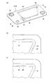
- FIG.7 (a) is a perspective view of the heat-transfer plate arrange
- FIG.7 (b) and FIG.7 (c) are refrigerant
- FIG. 8 shows a second embodiment of the present invention, and is a cross-sectional view taken along the line BB of FIG. 7 (a).
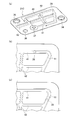
- Fig.9 (a) is a perspective view of the heat-transfer plate arrange
- FIG. 10 shows a third embodiment of the present invention, and is a perspective view of a heat transfer plate disposed at one end in the stacking direction.
- FIG. 11 shows a third embodiment of the present invention, and is a sectional view taken along the line CC of FIG.
- First Embodiment 1 to 6 show a first embodiment of the present invention.
- the air conditioner for a vehicle includes a heat pump type refrigeration cycle 1, a hot water cycle 10, and a control unit (not shown) that controls these.
- the refrigeration cycle 1 includes a compressor 2 that compresses a refrigerant RF, a water-cooled condenser 3A that is a heat exchanger that exchanges heat between the refrigerant RF compressed by the compressor 2 and hot water, and a refrigerant passage 5a of the water-cooled condenser 3A.
- An outdoor heat exchanger 7 which exchanges heat between the refrigerant RF which has been used or the refrigerant RF bypassed with the water-cooled condenser 3A and the outside air, and a second orifice 6b which decompresses the refrigerant RF which has exited the outdoor heat exchanger 7;
- the indoor heat exchanger 8 exchanges heat between the refrigerant RF decompressed (expanded) by the second orifice 6 b and the air supplied into the room, and the second bypass bypassing the indoor heat exchanger 8
- a water pump 11 for circulating hot water (heated cooling water CW)
- a water cooling condenser 3A through which the hot water circulated by the water pump 11 passes and the passing hot water is heated by the refrigerant RF
- the heater core 12 exchanges heat between the hot water circulated by the pump 11 and the air supplied into the vehicle compartment, and heats the air.
- the indoor heat exchanger 8 and the heater core 12 are disposed in the air flow path 30 of the air conditioning unit, and the downstream side of the air conditioning unit is connected to the air outlet (not shown) of the vehicle compartment by a duct (not shown).
- the first on-off valve 5a is in the open position, and the second on-off valve 5b is in the closed position.
- the outdoor heat exchanger 7 functions as a condenser
- the indoor heat exchanger 8 functions as an evaporator
- cold air is introduced into the vehicle interior.
- the first on-off valve 5a is in the closed position, and the second on-off valve 5b is in the open position.
- the water-cooled condenser 3A functions as a condenser, and the outdoor heat exchanger 7 functions as an evaporator. Then, the hot water of the hot water cycle 10 is circulated, the water cooling condenser 3A of the refrigeration cycle 1 heats the hot water of the hot water cycle 10 to heat the heater core 12, and the warm air is introduced into the vehicle compartment.
- An inlet side passage 21 connected to the refrigerant inlet 36 of the water-cooled condenser 3A, an outlet side passage 22 connected to the refrigerant outlet 37, a first bypass passage 4a, and a first orifice 6a are formed in the inlet / outlet block 20 .
- the entrance block 20 will be described in detail below.
- a partial passage 26 connecting the outdoor heat exchanger 7 and the indoor heat exchanger 8, a partial passage 27 connecting the indoor heat exchanger 8 and the accumulator 9, a second bypass passage 4b, and a second on-off valve 5b are passage blocks. 25 is formed.
- the water-cooled condenser 3A has a large number of heat transfer plates 31, 31A, and a large number of heat transfer plates 31, 31A are stacked.
- the heat transfer plates 31 and 31A have a rectangular shape.
- a cooling water passage through which the cooling water CW flows between two adjacent heat transfer plates 31 in the stacking direction. 32 and a refrigerant passage 33 through which the refrigerant RF flows are respectively formed.
- the cooling water passages 32 and the refrigerant passages 33 are alternately arranged in the stacking direction.
- the cooling water passages 32 are branched into a plurality of rows in the laminated body, and each row is formed in the same flow direction. That is, the flow of the cooling water CW is a so-called one pass.
- the refrigerant passage 33 is also branched into a plurality of rows in the stacked body, and each row is formed in the same flow direction. That is, the flow of the refrigerant RF is a so-called one pass (see the flow of the refrigerant RF in FIG. 4).
- a cooling water inlet 34 for introducing the cooling water CW from the outside into the cooling water passage 32 and a cooling water CW from the cooling water passage 32 to the heat transfer plate 31A disposed at one end in the stacking direction.
- the cooling water outlet 35 that flows out, the refrigerant inlet 36 that flows the refrigerant RF from the outside into the refrigerant passage 33, and the refrigerant outlet 37 that flows the refrigerant RF out of the refrigerant passage 33 are provided.
- the cooling water inlet 34 and the cooling water outlet 35 are respectively disposed at diagonally different corners (corners) of the heat transfer plate 31A.
- the refrigerant inlet 36 and the refrigerant outlet 37 are arranged at corners (corners) of the heat transfer plate 31A different from the arrangement positions of the cooling water inlet 34 and the cooling water outlet 35, and the refrigerant inlet 36 and the refrigerant flow
- the outlet 37 is disposed close to one another.
- a refrigerant return passage 40 is formed inside the heat transfer plate 31A disposed at one end in the stacking direction. Specifically, the refrigerant return passage 40 is formed between the heat transfer plate 31A disposed at one end in the stacking direction and the adjacent heat transfer plate 31 in the stacking direction of the heat transfer plate 31A. .
- the outlet 38 of the refrigerant passage 33 in the stack of the heat transfer plates 31 is open to the refrigerant return passage 40.
- the heat transfer plate 31A is provided with a passage projection 41 projecting upward, and the passage projection 41 forms a refrigerant return passage 40.
- the refrigerant return passage 40 linearly connects the outlet 38 of the refrigerant RF of the stack of the heat transfer plate 31 and the refrigerant outlet 37.
- the inlet / outlet block 20 includes an inlet side passage 21 connected to the refrigerant inlet 36 and an outlet side passage 22 connected to the refrigerant outlet 37. It has a passage group consisting of the inlet side passage 21 and the first bypass passage 4 a connecting the outlet side passage 22.
- the inlet / outlet block 20 has, as passage adjusting means, a first on-off valve 5a for opening and closing the first bypass passage 4a and a first orifice 6a provided in the outlet side passage 22.
- the first on-off valve is an electromagnetic type, and the first bypass passage 4a is located at the closed position when the power is not supplied as shown in FIG. 5A, and the refrigerant RF flows to the water-cooled condenser 3A, as shown in FIG. During the energization shown in FIG. 6, the first bypass passage 4a is located at the open position, and the refrigerant RF bypasses the water cooling condenser 3A (see FIG. 6).
- the refrigerant return passage 40 is formed inside the heat transfer plate 31A disposed at one end in the stacking direction. Specifically, the refrigerant return passage 40 is formed between the heat transfer plate 31A disposed at one end in the stacking direction and the adjacent heat transfer plate 31 in the stacking direction of the heat transfer plate 31A. .
- the refrigerant return passage 40 can be freely set as long as it is a space excluding the portion where the cooling water inlet 34, the cooling water outlet 35, and the refrigerant inlet 36 are provided.
- the refrigerant outlet 37 can be set close to the refrigerant inlet 36. Therefore, it is possible to provide a water-cooled condenser 3A having a high degree of freedom in the installation position of the refrigerant outlet 37.
- the inlet (refrigerant inlet 36) of the refrigerant RF entering the stack of the heat plates 31, 31A and the set of outlet (refrigerant outlet 37) of the refrigerant RF exiting the stack of the heat transfer plate 31 They are respectively formed on different diagonals.
- the cooling water inlet 34, the cooling water outlet 35, the refrigerant inlet 36, and the refrigerant outlet 37 are respectively formed at different corners (corners) of the heat transfer plate 31A.
- the cooling water CW flows without shorting the cooling water passage 32 (shown in FIG. 3A) in one pass as much as possible and without stagnating.
- the refrigerant RF flows without short-circuiting the one-pass refrigerant passage 33 (shown in FIG. 3B) as much as possible and without stagnating. Therefore, even if the refrigerant inlet 36 and the refrigerant outlet 37 are disposed close to the heat transfer plate 31A, the heat exchange property is not reduced.
- both sets of the cooling water inlet 34 and the cooling water outlet 35, and the sets of the refrigerant inlet 36 and the refrigerant outlet 37 are arranged together. ing. Therefore, since the inlets 34 and 36 and the outlets 35 and 37 of both the cooling water passage 32 and the refrigerant passage 33 are disposed on the same heat transfer plate 31A, the flows on both the cooling water passage 32 side and the refrigerant passage 33 side.
- the piping connection to the inlets 34 and 36 and the outlets 35 and 37 is good and the layout is also good.
- the heat transfer plate 31A disposed at one end in the stacking direction includes a passage group connected to the refrigerant inlet 36 and the refrigerant outlet 37 disposed close to each other and the passage adjusting means (passage switching means, passage resistance means).
- the entrance block 20 which has is fixed. Therefore, by attaching the inlet / outlet block 20 to the heat transfer plate 31A, it is possible to attach the parts connected to the refrigerant inlet 36 and the refrigerant outlet 37 of the water-cooled condenser 3A and the parts disposed in the vicinity thereof. Good sex, good layout.
- the heat exchanger is a water-cooled condenser 3A
- the passage group of the inlet / outlet block 20 includes an inlet side passage 21 connected to the refrigerant inlet 36 and an outlet side passage 22 connected to the refrigerant outlet 37, an inlet side passage 21 and an outlet
- the first bypass passage 4 a connects the side passages 22, and the passage adjustment means is a first on-off valve 5 a for opening and closing the first bypass passage 4 a and a first orifice 6 a provided in the outlet side passage 22. Therefore, the refrigeration cycle 1 that can be used selectively at the time of heating using the water-cooled condenser 3A and at the time of cooling not using the water-cooled condenser 3A can be configured to have high layout characteristics with a small number of parts.
- Second Embodiment 7 (a) and 8 show a second embodiment of the present invention.
- the heat transfer plate 31B is provided with two passage projections 41, and the two passage projections 41 form two refrigerant return passages 40 on the inside thereof. There is.
- the two refrigerant return passages 40 respectively communicate between the outlet 38 and the refrigerant outlet 37 of the stack of the heat transfer plates 31B.
- the water-cooled condenser 3B having a high degree of freedom in the installation position of the refrigerant outlet 37 can be provided for the same reason as the first embodiment.
- the second embodiment since two refrigerant return passages 40 are formed, reduction in flatness of the heat transfer plate 31B due to thinning due to processing and processing distortion can be prevented as much as possible. Brazing defects can be suppressed by preventing the reduction in flatness. That is, when there is one refrigerant return passage 40 as in the first embodiment, in order to secure a passage cross-sectional area equal to or more than a predetermined value, the flatness of the heat transfer plate 31A is reduced due to thickness reduction due to processing or processing distortion. Although there is a high risk of causing the heat transfer plate 31B of the second embodiment, such a fear can be prevented as much as possible.
- the height h2 of the refrigerant return passage 40 is higher than the height h1 of the refrigerant return passage 40 of the first embodiment (FIG. 3B). ( Figure 8) can be lowered. Thereby, the height H2 of the inlet / outlet block 20 can be made smaller than the height H1 of the inlet / outlet block 20 of the first embodiment, and the stacking direction of the water-cooled condenser (heat exchanger) can be made compact.
- two refrigerant return passages 40 are provided, but three or more refrigerant return passages may be provided.
- the position of the outlet 38 of the refrigerant RF may not be a corner but may be a straight line.
- FIG. 9A shows a heat transfer plate 31C according to a third embodiment of the present invention.
- the heat transfer plate 31C is provided with two passage projections 41 as in the second embodiment, and two refrigerant return passages are formed by the two passage projections 41. 40 are formed.
- the projection 42 is provided separately from the passage projection 41.
- the protrusions 42 are disposed substantially in the shape of a cross in the plane of the heat transfer plate 31B. Specifically, the projection 42 is disposed over the area surrounded by the two passage projections 41 and the outer area surrounded by the two passage projections 41. Since the projection 42 is connected to the passage projection 41 at the straight portion, the function of flowing the refrigerant RF is small. As described above, since the function of flowing the refrigerant RF is small in the protrusion 42, the passage protrusion 41 does not have to have the same flow path cross section.
- FIG. 9A the same reference numerals are given to the same components in the drawings and the description is omitted.
- the other configuration of the water-cooled condenser 3C according to the third embodiment is the same as that of the first embodiment, so the description will be omitted.
- the water-cooled condenser 3C having a high degree of freedom in the installation position of the refrigerant outlet 37 can be provided for the same reason as the first embodiment.
- the heat transfer plate 31C is provided with the protrusion 42 together with the passage protrusion 41, it is easy to ensure the processability and the rigidity of the heat transfer plate 31C.
- two refrigerant return passages 40 are provided, but three or more refrigerant return passages may be provided.
- the position of the outlet 38 of the refrigerant RF may not be a corner but may be a straight line.
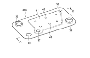
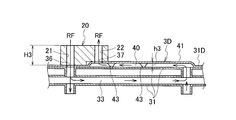
- Fourth Embodiment 10 and 11 show a fourth embodiment of the present invention.
- the heat transfer plate 31D is provided with a wide passage projection 41 by a space of half or more of the entire surface area, and the wide passage return refrigerant 40 is formed inside by the passage projection 41.
- the wide coolant return passage 40 communicates between the outlet 38 of the stack of the heat transfer plates 31D and the coolant outlet 37, respectively.
- Reinforcing ribs 43 that abut the heat transfer plate 31 are provided at a plurality of locations of the passage projection 41.
- FIG. 10 and FIG. 11 the same reference numerals are given to the same components in the drawings and the description will be omitted.
- the other configuration of the water-cooled condenser 3D according to the fourth embodiment is the same as that of the first embodiment, so the description will be omitted.
- the water-cooled condenser 3D having a high degree of freedom in the installation position of the refrigerant outlet 37 can be provided for the same reason as in the first embodiment.
- the refrigerant return passage 40 is formed in the space of half or more of the total area of the heat transfer plate 31D, the height h2 (FIG. 8) of the passage projection 41 of the second embodiment The height h3 of the refrigerant return passage 40 can be reduced. As a result, the height H3 of the inlet / outlet block 20 can be made smaller than the height H2 of the outlet / inlet block 20 of the second embodiment, and further downsizing of the water-cooled condenser (heat exchanger) in the stacking direction can be achieved.
- the refrigerant return passage 40 can be maximally formed in almost the entire space of the heat transfer plate 31D, specifically, the entire space excluding the cooling water inlet 34, the cooling water outlet 35, and the portion where the refrigerant inlet 36 is provided.
- the refrigerant outlet 37 is disposed close to the refrigerant inlet 36, but the present invention is not limited to this. That is, when there is a dead space outside the heat transfer plates 31A to 31D arranged in one of the stacking directions, the refrigerant outlet 37 may be installed in the dead space in order to effectively use the dead space. It is possible. When there is an installation space for external parts outside heat transfer plates 31A to 31D arranged in one of the stacking directions, it is possible to install refrigerant outlet 37 so as to avoid the installation space for external parts. .
- the flow of the cooling water CW is one pass, but may be a plurality of passes.
- the refrigerant return passage can be freely set as long as it is a space excluding the cooling water inlet, the cooling water outlet, and the part where the refrigerant inlet is provided, the degree of freedom of the installation position of the refrigerant outlet is It can provide a high heat exchanger.
Landscapes
- Engineering & Computer Science (AREA)
- Physics & Mathematics (AREA)
- Thermal Sciences (AREA)
- Mechanical Engineering (AREA)
- General Engineering & Computer Science (AREA)
- Heat-Exchange Devices With Radiators And Conduit Assemblies (AREA)
- Details Of Heat-Exchange And Heat-Transfer (AREA)
- Air-Conditioning For Vehicles (AREA)
Priority Applications (1)
| Application Number | Priority Date | Filing Date | Title |
|---|---|---|---|
| CN201780055820.2A CN109690225A (zh) | 2016-09-14 | 2017-08-30 | 热交换器 |
Applications Claiming Priority (2)
| Application Number | Priority Date | Filing Date | Title |
|---|---|---|---|
| JP2016179410A JP2018044710A (ja) | 2016-09-14 | 2016-09-14 | 熱交換器 |
| JP2016-179410 | 2016-09-14 |
Publications (1)
| Publication Number | Publication Date |
|---|---|
| WO2018051786A1 true WO2018051786A1 (ja) | 2018-03-22 |
Family
ID=61619117
Family Applications (1)
| Application Number | Title | Priority Date | Filing Date |
|---|---|---|---|
| PCT/JP2017/031082 Ceased WO2018051786A1 (ja) | 2016-09-14 | 2017-08-30 | 熱交換器 |
Country Status (3)
| Country | Link |
|---|---|
| JP (1) | JP2018044710A (enExample) |
| CN (1) | CN109690225A (enExample) |
| WO (1) | WO2018051786A1 (enExample) |
Families Citing this family (1)
| Publication number | Priority date | Publication date | Assignee | Title |
|---|---|---|---|---|
| JP7047577B2 (ja) | 2018-04-27 | 2022-04-05 | 株式会社デンソー | 熱交換器 |
Citations (9)
| Publication number | Priority date | Publication date | Assignee | Title |
|---|---|---|---|---|
| EP0623798A2 (de) * | 1993-05-05 | 1994-11-09 | Behr GmbH & Co. | Plattenwärmetauscher, insbesondere Öl/Kühlmittel-Kühler |
| JPH11506532A (ja) * | 1995-06-02 | 1999-06-08 | フイルテルウエルク マン ウント フンメル ゲゼルシヤフト ミツト ベシユレンクテル ハフツング | 熱交換器 |
| JP2012112562A (ja) * | 2010-11-23 | 2012-06-14 | Mitsubishi Electric Corp | ドロンカップ型熱交換器 |
| JP2013113579A (ja) * | 2011-11-25 | 2013-06-10 | Hyundai Motor Co Ltd | 車両用熱交換器 |
| JP2014163639A (ja) * | 2013-02-27 | 2014-09-08 | Denso Corp | 積層型熱交換器 |
| JP2014535031A (ja) * | 2011-11-16 | 2014-12-25 | キュンドン ナビエン シーオー.,エルティーディー. | 給湯熱交換器 |
| WO2015042721A1 (en) * | 2013-09-30 | 2015-04-02 | Dana Canada Corporation | Heat exchanger with integrated co-axial inlet/outlet tube |
| JP2016125686A (ja) * | 2014-12-26 | 2016-07-11 | 株式会社マーレ フィルターシステムズ | オイルクーラ |
| JP2017015278A (ja) * | 2015-06-29 | 2017-01-19 | カルソニックカンセイ株式会社 | 熱交換器 |
Family Cites Families (2)
| Publication number | Priority date | Publication date | Assignee | Title |
|---|---|---|---|---|
| JP4328445B2 (ja) * | 2000-03-01 | 2009-09-09 | 昭和電工株式会社 | 積層型熱交換器 |
| CN105074375B (zh) * | 2013-02-27 | 2018-05-15 | 株式会社电装 | 层叠型热交换器 |
-
2016
- 2016-09-14 JP JP2016179410A patent/JP2018044710A/ja active Pending
-
2017
- 2017-08-30 WO PCT/JP2017/031082 patent/WO2018051786A1/ja not_active Ceased
- 2017-08-30 CN CN201780055820.2A patent/CN109690225A/zh active Pending
Patent Citations (9)
| Publication number | Priority date | Publication date | Assignee | Title |
|---|---|---|---|---|
| EP0623798A2 (de) * | 1993-05-05 | 1994-11-09 | Behr GmbH & Co. | Plattenwärmetauscher, insbesondere Öl/Kühlmittel-Kühler |
| JPH11506532A (ja) * | 1995-06-02 | 1999-06-08 | フイルテルウエルク マン ウント フンメル ゲゼルシヤフト ミツト ベシユレンクテル ハフツング | 熱交換器 |
| JP2012112562A (ja) * | 2010-11-23 | 2012-06-14 | Mitsubishi Electric Corp | ドロンカップ型熱交換器 |
| JP2014535031A (ja) * | 2011-11-16 | 2014-12-25 | キュンドン ナビエン シーオー.,エルティーディー. | 給湯熱交換器 |
| JP2013113579A (ja) * | 2011-11-25 | 2013-06-10 | Hyundai Motor Co Ltd | 車両用熱交換器 |
| JP2014163639A (ja) * | 2013-02-27 | 2014-09-08 | Denso Corp | 積層型熱交換器 |
| WO2015042721A1 (en) * | 2013-09-30 | 2015-04-02 | Dana Canada Corporation | Heat exchanger with integrated co-axial inlet/outlet tube |
| JP2016125686A (ja) * | 2014-12-26 | 2016-07-11 | 株式会社マーレ フィルターシステムズ | オイルクーラ |
| JP2017015278A (ja) * | 2015-06-29 | 2017-01-19 | カルソニックカンセイ株式会社 | 熱交換器 |
Also Published As
| Publication number | Publication date |
|---|---|
| JP2018044710A (ja) | 2018-03-22 |
| CN109690225A (zh) | 2019-04-26 |
Similar Documents
| Publication | Publication Date | Title |
|---|---|---|
| JP6644154B2 (ja) | 空気調和装置 | |
| JP6317920B2 (ja) | 車両用熱交換機 | |
| KR101776718B1 (ko) | 차량용 열교환기 | |
| CN107208983B (zh) | 板式热交换器以及热泵式室外机 | |
| WO2018116413A1 (ja) | 分配器、熱交換器、及び、冷凍サイクル装置 | |
| JP2009236404A (ja) | 冷凍サイクル装置 | |
| CN109564070B (zh) | 热交换器和使用它的制冷系统 | |
| CN102869942A (zh) | 车室内热交换器 | |
| WO2012063355A1 (ja) | プレート式熱交換器及びヒートポンプ装置 | |
| KR102470436B1 (ko) | 차량용 히트펌프 시스템 | |
| JP2012002425A (ja) | プレート式熱交換器及びヒートポンプ装置 | |
| CN118076854A (zh) | 具有积聚装置的热调节模块 | |
| JP2017015278A (ja) | 熱交換器 | |
| JPWO2018179311A1 (ja) | 熱交換器およびそれを備えた冷凍サイクル装置 | |
| JP6026956B2 (ja) | 室内熱交換器 | |
| JP2006329511A (ja) | 熱交換器 | |
| JP3985831B2 (ja) | 室外ユニット用熱交換器 | |
| WO2018051786A1 (ja) | 熱交換器 | |
| JP5498359B2 (ja) | マルチ型温調システム | |
| WO2017163563A1 (ja) | 熱交換ユニットおよび車両用空調装置 | |
| CN112105884B (zh) | 热交换器 | |
| CN117628941A (zh) | 一种三流体换热器、热管理系统及热管理设备 | |
| JP2025059318A (ja) | 熱交換器ユニット、空調室内機、および冷凍サイクル装置 | |
| JP2025059317A (ja) | 熱交換器ユニット、空調室内機、および冷凍サイクル装置 | |
| KR20230143451A (ko) | 차량용 히트펌프 시스템의 냉매용 모듈 |
Legal Events
| Date | Code | Title | Description |
|---|---|---|---|
| 121 | Ep: the epo has been informed by wipo that ep was designated in this application |
Ref document number: 17850689 Country of ref document: EP Kind code of ref document: A1 |
|
| NENP | Non-entry into the national phase |
Ref country code: DE |
|
| 122 | Ep: pct application non-entry in european phase |
Ref document number: 17850689 Country of ref document: EP Kind code of ref document: A1 |