WO2018051786A1 - Heat exchanger - Google Patents
Heat exchanger Download PDFInfo
- Publication number
- WO2018051786A1 WO2018051786A1 PCT/JP2017/031082 JP2017031082W WO2018051786A1 WO 2018051786 A1 WO2018051786 A1 WO 2018051786A1 JP 2017031082 W JP2017031082 W JP 2017031082W WO 2018051786 A1 WO2018051786 A1 WO 2018051786A1
- Authority
- WO
- WIPO (PCT)
- Prior art keywords
- refrigerant
- passage
- outlet
- cooling water
- heat transfer
- Prior art date
Links
Images


Classifications
-
- B—PERFORMING OPERATIONS; TRANSPORTING
- B60—VEHICLES IN GENERAL
- B60H—ARRANGEMENTS OF HEATING, COOLING, VENTILATING OR OTHER AIR-TREATING DEVICES SPECIALLY ADAPTED FOR PASSENGER OR GOODS SPACES OF VEHICLES
- B60H1/00—Heating, cooling or ventilating [HVAC] devices
- B60H1/32—Cooling devices
-
- F—MECHANICAL ENGINEERING; LIGHTING; HEATING; WEAPONS; BLASTING
- F25—REFRIGERATION OR COOLING; COMBINED HEATING AND REFRIGERATION SYSTEMS; HEAT PUMP SYSTEMS; MANUFACTURE OR STORAGE OF ICE; LIQUEFACTION SOLIDIFICATION OF GASES
- F25B—REFRIGERATION MACHINES, PLANTS OR SYSTEMS; COMBINED HEATING AND REFRIGERATION SYSTEMS; HEAT PUMP SYSTEMS
- F25B39/00—Evaporators; Condensers
- F25B39/04—Condensers
-
- F—MECHANICAL ENGINEERING; LIGHTING; HEATING; WEAPONS; BLASTING
- F28—HEAT EXCHANGE IN GENERAL
- F28D—HEAT-EXCHANGE APPARATUS, NOT PROVIDED FOR IN ANOTHER SUBCLASS, IN WHICH THE HEAT-EXCHANGE MEDIA DO NOT COME INTO DIRECT CONTACT
- F28D9/00—Heat-exchange apparatus having stationary plate-like or laminated conduit assemblies for both heat-exchange media, the media being in contact with different sides of a conduit wall
- F28D9/02—Heat-exchange apparatus having stationary plate-like or laminated conduit assemblies for both heat-exchange media, the media being in contact with different sides of a conduit wall the heat-exchange media travelling at an angle to one another
-
- F—MECHANICAL ENGINEERING; LIGHTING; HEATING; WEAPONS; BLASTING
- F28—HEAT EXCHANGE IN GENERAL
- F28F—DETAILS OF HEAT-EXCHANGE AND HEAT-TRANSFER APPARATUS, OF GENERAL APPLICATION
- F28F3/00—Plate-like or laminated elements; Assemblies of plate-like or laminated elements
- F28F3/02—Elements or assemblies thereof with means for increasing heat-transfer area, e.g. with fins, with recesses, with corrugations
- F28F3/04—Elements or assemblies thereof with means for increasing heat-transfer area, e.g. with fins, with recesses, with corrugations the means being integral with the element
-
- F—MECHANICAL ENGINEERING; LIGHTING; HEATING; WEAPONS; BLASTING
- F28—HEAT EXCHANGE IN GENERAL
- F28F—DETAILS OF HEAT-EXCHANGE AND HEAT-TRANSFER APPARATUS, OF GENERAL APPLICATION
- F28F3/00—Plate-like or laminated elements; Assemblies of plate-like or laminated elements
- F28F3/08—Elements constructed for building-up into stacks, e.g. capable of being taken apart for cleaning
-
- F—MECHANICAL ENGINEERING; LIGHTING; HEATING; WEAPONS; BLASTING
- F28—HEAT EXCHANGE IN GENERAL
- F28F—DETAILS OF HEAT-EXCHANGE AND HEAT-TRANSFER APPARATUS, OF GENERAL APPLICATION
- F28F9/00—Casings; Header boxes; Auxiliary supports for elements; Auxiliary members within casings
- F28F9/22—Arrangements for directing heat-exchange media into successive compartments, e.g. arrangements of guide plates
Definitions
- the present invention relates to a heat exchanger in which heat transfer plates are stacked.
- a water-cooled condenser which is a heat exchanger, has a refrigerant passage through which the refrigerant passes and a cooling water passage through which the cooling water passes in the heat exchanger. The heat is exchanged and the refrigerant is cooled by the cooling water.
- Such a water-cooled condenser is configured by laminating a large number of heat transfer plates, and a refrigerant passage and a cooling water passage are respectively formed between adjacent heat transfer plates.
- the refrigerant passage and the cooling water passage are alternately formed with the heat transfer plates as partitions, and the refrigerant and the cooling water exchange heat via the heat transfer plate.
- a cooling water inlet, a cooling water outlet, and a refrigerant inlet are formed on the heat transfer plate disposed at one end in the stacking direction.
- the heat transfer plate disposed at the other end in the stacking direction is formed with a refrigerant outlet and a refrigerant inlet and a refrigerant outlet for the subcooling unit, in addition to the refrigerant outlet.
- the inlets / outlets (four in total when there is no subcooling portion) of the cooling water and the refrigerant are provided separately for the two heat transfer plates disposed at both ends in the lamination direction There is.
- the cooling water inlet and the cooling water outlet are at the corners of the diagonal of the square heat transfer plate (corners It is usually formed in.
- the refrigerant inlet and the refrigerant outlet are also preferably formed at diagonal corner portions of the square heat transfer plate from the viewpoint of improving heat exchange.
- restriction is required on the installation position of the refrigerant outlet from the viewpoint of component installation of the refrigeration cycle, effective use of dead space, etc.
- the degree of freedom of the installation position of the refrigerant outlet may be limited.
- an object of this invention is to provide the heat exchanger with a high freedom degree of the installation position of a refrigerant
- a cooling water passage through which cooling water flows and a refrigerant passage through which refrigerant of the refrigeration cycle flows are respectively formed between two adjacent heat transfer plates in the stacking direction, and the stacking direction
- the cooling water flow inlet externally flows the cooling water into the cooling water passage and the cooling water flow outlet flowing the cooling water to the outside from the cooling water passage
- Heat exchanger provided with a refrigerant outlet and a refrigerant outlet for discharging the refrigerant to the outside from the refrigerant passage, the heat transfer plate disposed at one end of the stacking direction, the coolant inlet and the coolant outlet, and the refrigerant flow
- a heat is characterized in that a refrigerant return passage for returning the refrigerant to the refrigerant outlet is formed inside the heat transfer plate provided with both the inlet and the refrigerant outlet and arranged at one end in the stacking direction.
- FIG. 1 shows a first embodiment of the present invention, and is a configuration diagram of a vehicle air conditioner.
- FIG. 2 shows a first embodiment of the present invention and is a schematic perspective view of a water-cooled condenser.
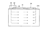
- Fig.3 (a) is principal part sectional drawing of the water-cooled condenser which shows the flow of a cooling water based on 1st Embodiment of this invention
- FIG.3 (b) is a refrigerant based on 1st Embodiment of this invention. It is principal part sectional drawing of the water-cooled condenser which shows a flow.
- FIG. 4 shows a first embodiment of the present invention, and is a conceptual view showing the flow of the refrigerant in the entire water-cooled condenser.
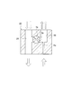
- FIG.5 (a) is a schematic sectional drawing of the entrance / exit block which a solenoid valve is in a closed position based on 1st Embodiment of this invention
- FIG.5 (b) is a solenoid valve based on 1st Embodiment of this invention. Is a schematic cross-sectional view of the entrance block in the open position.
- FIG. 6 shows a first embodiment of the present invention, and is a schematic view showing the flow of the refrigerant in the inlet / outlet block.
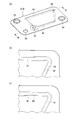
- FIG.7 (a) is a perspective view of the heat-transfer plate arrange
- FIG.7 (b) and FIG.7 (c) are refrigerant
- FIG. 8 shows a second embodiment of the present invention, and is a cross-sectional view taken along the line BB of FIG. 7 (a).
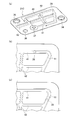
- Fig.9 (a) is a perspective view of the heat-transfer plate arrange
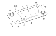
- FIG. 10 shows a third embodiment of the present invention, and is a perspective view of a heat transfer plate disposed at one end in the stacking direction.
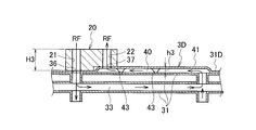
- FIG. 11 shows a third embodiment of the present invention, and is a sectional view taken along the line CC of FIG.
- First Embodiment 1 to 6 show a first embodiment of the present invention.
- the air conditioner for a vehicle includes a heat pump type refrigeration cycle 1, a hot water cycle 10, and a control unit (not shown) that controls these.
- the refrigeration cycle 1 includes a compressor 2 that compresses a refrigerant RF, a water-cooled condenser 3A that is a heat exchanger that exchanges heat between the refrigerant RF compressed by the compressor 2 and hot water, and a refrigerant passage 5a of the water-cooled condenser 3A.
- An outdoor heat exchanger 7 which exchanges heat between the refrigerant RF which has been used or the refrigerant RF bypassed with the water-cooled condenser 3A and the outside air, and a second orifice 6b which decompresses the refrigerant RF which has exited the outdoor heat exchanger 7;
- the indoor heat exchanger 8 exchanges heat between the refrigerant RF decompressed (expanded) by the second orifice 6 b and the air supplied into the room, and the second bypass bypassing the indoor heat exchanger 8
- a water pump 11 for circulating hot water (heated cooling water CW)
- a water cooling condenser 3A through which the hot water circulated by the water pump 11 passes and the passing hot water is heated by the refrigerant RF
- the heater core 12 exchanges heat between the hot water circulated by the pump 11 and the air supplied into the vehicle compartment, and heats the air.
- the indoor heat exchanger 8 and the heater core 12 are disposed in the air flow path 30 of the air conditioning unit, and the downstream side of the air conditioning unit is connected to the air outlet (not shown) of the vehicle compartment by a duct (not shown).
- the first on-off valve 5a is in the open position, and the second on-off valve 5b is in the closed position.
- the outdoor heat exchanger 7 functions as a condenser
- the indoor heat exchanger 8 functions as an evaporator
- cold air is introduced into the vehicle interior.
- the first on-off valve 5a is in the closed position, and the second on-off valve 5b is in the open position.
- the water-cooled condenser 3A functions as a condenser, and the outdoor heat exchanger 7 functions as an evaporator. Then, the hot water of the hot water cycle 10 is circulated, the water cooling condenser 3A of the refrigeration cycle 1 heats the hot water of the hot water cycle 10 to heat the heater core 12, and the warm air is introduced into the vehicle compartment.
- An inlet side passage 21 connected to the refrigerant inlet 36 of the water-cooled condenser 3A, an outlet side passage 22 connected to the refrigerant outlet 37, a first bypass passage 4a, and a first orifice 6a are formed in the inlet / outlet block 20 .
- the entrance block 20 will be described in detail below.
- a partial passage 26 connecting the outdoor heat exchanger 7 and the indoor heat exchanger 8, a partial passage 27 connecting the indoor heat exchanger 8 and the accumulator 9, a second bypass passage 4b, and a second on-off valve 5b are passage blocks. 25 is formed.
- the water-cooled condenser 3A has a large number of heat transfer plates 31, 31A, and a large number of heat transfer plates 31, 31A are stacked.
- the heat transfer plates 31 and 31A have a rectangular shape.
- a cooling water passage through which the cooling water CW flows between two adjacent heat transfer plates 31 in the stacking direction. 32 and a refrigerant passage 33 through which the refrigerant RF flows are respectively formed.
- the cooling water passages 32 and the refrigerant passages 33 are alternately arranged in the stacking direction.
- the cooling water passages 32 are branched into a plurality of rows in the laminated body, and each row is formed in the same flow direction. That is, the flow of the cooling water CW is a so-called one pass.
- the refrigerant passage 33 is also branched into a plurality of rows in the stacked body, and each row is formed in the same flow direction. That is, the flow of the refrigerant RF is a so-called one pass (see the flow of the refrigerant RF in FIG. 4).
- a cooling water inlet 34 for introducing the cooling water CW from the outside into the cooling water passage 32 and a cooling water CW from the cooling water passage 32 to the heat transfer plate 31A disposed at one end in the stacking direction.
- the cooling water outlet 35 that flows out, the refrigerant inlet 36 that flows the refrigerant RF from the outside into the refrigerant passage 33, and the refrigerant outlet 37 that flows the refrigerant RF out of the refrigerant passage 33 are provided.
- the cooling water inlet 34 and the cooling water outlet 35 are respectively disposed at diagonally different corners (corners) of the heat transfer plate 31A.
- the refrigerant inlet 36 and the refrigerant outlet 37 are arranged at corners (corners) of the heat transfer plate 31A different from the arrangement positions of the cooling water inlet 34 and the cooling water outlet 35, and the refrigerant inlet 36 and the refrigerant flow
- the outlet 37 is disposed close to one another.
- a refrigerant return passage 40 is formed inside the heat transfer plate 31A disposed at one end in the stacking direction. Specifically, the refrigerant return passage 40 is formed between the heat transfer plate 31A disposed at one end in the stacking direction and the adjacent heat transfer plate 31 in the stacking direction of the heat transfer plate 31A. .
- the outlet 38 of the refrigerant passage 33 in the stack of the heat transfer plates 31 is open to the refrigerant return passage 40.
- the heat transfer plate 31A is provided with a passage projection 41 projecting upward, and the passage projection 41 forms a refrigerant return passage 40.
- the refrigerant return passage 40 linearly connects the outlet 38 of the refrigerant RF of the stack of the heat transfer plate 31 and the refrigerant outlet 37.
- the inlet / outlet block 20 includes an inlet side passage 21 connected to the refrigerant inlet 36 and an outlet side passage 22 connected to the refrigerant outlet 37. It has a passage group consisting of the inlet side passage 21 and the first bypass passage 4 a connecting the outlet side passage 22.
- the inlet / outlet block 20 has, as passage adjusting means, a first on-off valve 5a for opening and closing the first bypass passage 4a and a first orifice 6a provided in the outlet side passage 22.
- the first on-off valve is an electromagnetic type, and the first bypass passage 4a is located at the closed position when the power is not supplied as shown in FIG. 5A, and the refrigerant RF flows to the water-cooled condenser 3A, as shown in FIG. During the energization shown in FIG. 6, the first bypass passage 4a is located at the open position, and the refrigerant RF bypasses the water cooling condenser 3A (see FIG. 6).
- the refrigerant return passage 40 is formed inside the heat transfer plate 31A disposed at one end in the stacking direction. Specifically, the refrigerant return passage 40 is formed between the heat transfer plate 31A disposed at one end in the stacking direction and the adjacent heat transfer plate 31 in the stacking direction of the heat transfer plate 31A. .
- the refrigerant return passage 40 can be freely set as long as it is a space excluding the portion where the cooling water inlet 34, the cooling water outlet 35, and the refrigerant inlet 36 are provided.
- the refrigerant outlet 37 can be set close to the refrigerant inlet 36. Therefore, it is possible to provide a water-cooled condenser 3A having a high degree of freedom in the installation position of the refrigerant outlet 37.
- the inlet (refrigerant inlet 36) of the refrigerant RF entering the stack of the heat plates 31, 31A and the set of outlet (refrigerant outlet 37) of the refrigerant RF exiting the stack of the heat transfer plate 31 They are respectively formed on different diagonals.
- the cooling water inlet 34, the cooling water outlet 35, the refrigerant inlet 36, and the refrigerant outlet 37 are respectively formed at different corners (corners) of the heat transfer plate 31A.
- the cooling water CW flows without shorting the cooling water passage 32 (shown in FIG. 3A) in one pass as much as possible and without stagnating.
- the refrigerant RF flows without short-circuiting the one-pass refrigerant passage 33 (shown in FIG. 3B) as much as possible and without stagnating. Therefore, even if the refrigerant inlet 36 and the refrigerant outlet 37 are disposed close to the heat transfer plate 31A, the heat exchange property is not reduced.
- both sets of the cooling water inlet 34 and the cooling water outlet 35, and the sets of the refrigerant inlet 36 and the refrigerant outlet 37 are arranged together. ing. Therefore, since the inlets 34 and 36 and the outlets 35 and 37 of both the cooling water passage 32 and the refrigerant passage 33 are disposed on the same heat transfer plate 31A, the flows on both the cooling water passage 32 side and the refrigerant passage 33 side.
- the piping connection to the inlets 34 and 36 and the outlets 35 and 37 is good and the layout is also good.
- the heat transfer plate 31A disposed at one end in the stacking direction includes a passage group connected to the refrigerant inlet 36 and the refrigerant outlet 37 disposed close to each other and the passage adjusting means (passage switching means, passage resistance means).
- the entrance block 20 which has is fixed. Therefore, by attaching the inlet / outlet block 20 to the heat transfer plate 31A, it is possible to attach the parts connected to the refrigerant inlet 36 and the refrigerant outlet 37 of the water-cooled condenser 3A and the parts disposed in the vicinity thereof. Good sex, good layout.
- the heat exchanger is a water-cooled condenser 3A
- the passage group of the inlet / outlet block 20 includes an inlet side passage 21 connected to the refrigerant inlet 36 and an outlet side passage 22 connected to the refrigerant outlet 37, an inlet side passage 21 and an outlet
- the first bypass passage 4 a connects the side passages 22, and the passage adjustment means is a first on-off valve 5 a for opening and closing the first bypass passage 4 a and a first orifice 6 a provided in the outlet side passage 22. Therefore, the refrigeration cycle 1 that can be used selectively at the time of heating using the water-cooled condenser 3A and at the time of cooling not using the water-cooled condenser 3A can be configured to have high layout characteristics with a small number of parts.
- Second Embodiment 7 (a) and 8 show a second embodiment of the present invention.
- the heat transfer plate 31B is provided with two passage projections 41, and the two passage projections 41 form two refrigerant return passages 40 on the inside thereof. There is.
- the two refrigerant return passages 40 respectively communicate between the outlet 38 and the refrigerant outlet 37 of the stack of the heat transfer plates 31B.
- the water-cooled condenser 3B having a high degree of freedom in the installation position of the refrigerant outlet 37 can be provided for the same reason as the first embodiment.
- the second embodiment since two refrigerant return passages 40 are formed, reduction in flatness of the heat transfer plate 31B due to thinning due to processing and processing distortion can be prevented as much as possible. Brazing defects can be suppressed by preventing the reduction in flatness. That is, when there is one refrigerant return passage 40 as in the first embodiment, in order to secure a passage cross-sectional area equal to or more than a predetermined value, the flatness of the heat transfer plate 31A is reduced due to thickness reduction due to processing or processing distortion. Although there is a high risk of causing the heat transfer plate 31B of the second embodiment, such a fear can be prevented as much as possible.
- the height h2 of the refrigerant return passage 40 is higher than the height h1 of the refrigerant return passage 40 of the first embodiment (FIG. 3B). ( Figure 8) can be lowered. Thereby, the height H2 of the inlet / outlet block 20 can be made smaller than the height H1 of the inlet / outlet block 20 of the first embodiment, and the stacking direction of the water-cooled condenser (heat exchanger) can be made compact.
- two refrigerant return passages 40 are provided, but three or more refrigerant return passages may be provided.
- the position of the outlet 38 of the refrigerant RF may not be a corner but may be a straight line.
- FIG. 9A shows a heat transfer plate 31C according to a third embodiment of the present invention.
- the heat transfer plate 31C is provided with two passage projections 41 as in the second embodiment, and two refrigerant return passages are formed by the two passage projections 41. 40 are formed.
- the projection 42 is provided separately from the passage projection 41.
- the protrusions 42 are disposed substantially in the shape of a cross in the plane of the heat transfer plate 31B. Specifically, the projection 42 is disposed over the area surrounded by the two passage projections 41 and the outer area surrounded by the two passage projections 41. Since the projection 42 is connected to the passage projection 41 at the straight portion, the function of flowing the refrigerant RF is small. As described above, since the function of flowing the refrigerant RF is small in the protrusion 42, the passage protrusion 41 does not have to have the same flow path cross section.
- FIG. 9A the same reference numerals are given to the same components in the drawings and the description is omitted.
- the other configuration of the water-cooled condenser 3C according to the third embodiment is the same as that of the first embodiment, so the description will be omitted.
- the water-cooled condenser 3C having a high degree of freedom in the installation position of the refrigerant outlet 37 can be provided for the same reason as the first embodiment.
- the heat transfer plate 31C is provided with the protrusion 42 together with the passage protrusion 41, it is easy to ensure the processability and the rigidity of the heat transfer plate 31C.
- two refrigerant return passages 40 are provided, but three or more refrigerant return passages may be provided.
- the position of the outlet 38 of the refrigerant RF may not be a corner but may be a straight line.
- Fourth Embodiment 10 and 11 show a fourth embodiment of the present invention.
- the heat transfer plate 31D is provided with a wide passage projection 41 by a space of half or more of the entire surface area, and the wide passage return refrigerant 40 is formed inside by the passage projection 41.
- the wide coolant return passage 40 communicates between the outlet 38 of the stack of the heat transfer plates 31D and the coolant outlet 37, respectively.
- Reinforcing ribs 43 that abut the heat transfer plate 31 are provided at a plurality of locations of the passage projection 41.
- FIG. 10 and FIG. 11 the same reference numerals are given to the same components in the drawings and the description will be omitted.
- the other configuration of the water-cooled condenser 3D according to the fourth embodiment is the same as that of the first embodiment, so the description will be omitted.
- the water-cooled condenser 3D having a high degree of freedom in the installation position of the refrigerant outlet 37 can be provided for the same reason as in the first embodiment.
- the refrigerant return passage 40 is formed in the space of half or more of the total area of the heat transfer plate 31D, the height h2 (FIG. 8) of the passage projection 41 of the second embodiment The height h3 of the refrigerant return passage 40 can be reduced. As a result, the height H3 of the inlet / outlet block 20 can be made smaller than the height H2 of the outlet / inlet block 20 of the second embodiment, and further downsizing of the water-cooled condenser (heat exchanger) in the stacking direction can be achieved.
- the refrigerant return passage 40 can be maximally formed in almost the entire space of the heat transfer plate 31D, specifically, the entire space excluding the cooling water inlet 34, the cooling water outlet 35, and the portion where the refrigerant inlet 36 is provided.
- the refrigerant outlet 37 is disposed close to the refrigerant inlet 36, but the present invention is not limited to this. That is, when there is a dead space outside the heat transfer plates 31A to 31D arranged in one of the stacking directions, the refrigerant outlet 37 may be installed in the dead space in order to effectively use the dead space. It is possible. When there is an installation space for external parts outside heat transfer plates 31A to 31D arranged in one of the stacking directions, it is possible to install refrigerant outlet 37 so as to avoid the installation space for external parts. .
- the flow of the cooling water CW is one pass, but may be a plurality of passes.
- the refrigerant return passage can be freely set as long as it is a space excluding the cooling water inlet, the cooling water outlet, and the part where the refrigerant inlet is provided, the degree of freedom of the installation position of the refrigerant outlet is It can provide a high heat exchanger.
Landscapes
- Engineering & Computer Science (AREA)
- Physics & Mathematics (AREA)
- Thermal Sciences (AREA)
- Mechanical Engineering (AREA)
- General Engineering & Computer Science (AREA)
- Heat-Exchange Devices With Radiators And Conduit Assemblies (AREA)
- Air-Conditioning For Vehicles (AREA)
- Details Of Heat-Exchange And Heat-Transfer (AREA)
Abstract
A heat exchanger (3A) in which rectangular heat-conducting plates (31) are stacked, cooling fluid channels and refrigerant channels are formed between two heat-conducting plates (31) that are adjacent in the stacking direction, and a heat-conducting plate (31) disposed at a stacking-direction end is provided with a cooling fluid inlet (34) and cooling fluid outlet (35) for the cooling fluid channel and with a refrigerant inlet (36) and refrigerant outlet (37) of the refrigerant channel, wherein both the group comprising the cooling fluid inlet (34) and the cooling fluid outlet (35) and the group comprising the refrigerant inlet (36) and the refrigerant outlet (37) are provided to a heat-conducting plate (31A) disposed at one stacking-direction end, and a refrigerant return channel (40) for returning refrigerant (RF) to the refrigerant outlet (37) is formed on the inner side of the heat-conducting plate (31A) disposed at the one stacking-direction end.
Description
本発明は、伝熱プレートを積層した熱交換器に関する。
The present invention relates to a heat exchanger in which heat transfer plates are stacked.
例えば、熱交換器である水冷コンデンサは、特許文献1に示すように、熱交換器内に冷媒が通過する冷媒通路と冷却水が通過する冷却水通路を有し、冷媒と冷却水の間で熱交換して冷媒を冷却水によって冷却する。
For example, as shown in Patent Document 1, a water-cooled condenser, which is a heat exchanger, has a refrigerant passage through which the refrigerant passes and a cooling water passage through which the cooling water passes in the heat exchanger. The heat is exchanged and the refrigerant is cooled by the cooling water.
このような水冷コンデンサは、伝熱プレートが多数積層することにより構成されており、隣り合う伝熱プレート間に冷媒通路と冷却水通路とがそれぞれ形成されている。冷媒通路と冷却水通路は、各伝熱プレートを仕切りとして交互に形成され、冷媒と冷却水が伝熱プレートを介して熱交換するようになっている。積層方向の一方の端に配置された伝熱プレートには、冷却水流入口と冷却水流出口と冷媒流入口が形成されている。積層方向の他方の端に配置された伝熱プレートには、冷媒流出口が形成されるほかに、過冷却部用の冷媒流入口及び冷媒流出口が形成されている。
Such a water-cooled condenser is configured by laminating a large number of heat transfer plates, and a refrigerant passage and a cooling water passage are respectively formed between adjacent heat transfer plates. The refrigerant passage and the cooling water passage are alternately formed with the heat transfer plates as partitions, and the refrigerant and the cooling water exchange heat via the heat transfer plate. A cooling water inlet, a cooling water outlet, and a refrigerant inlet are formed on the heat transfer plate disposed at one end in the stacking direction. The heat transfer plate disposed at the other end in the stacking direction is formed with a refrigerant outlet and a refrigerant inlet and a refrigerant outlet for the subcooling unit, in addition to the refrigerant outlet.
つまり、特許文献1に示す水冷コンデンサにおいて、冷却水及び冷媒の出入口(過冷却部がない場合、合計4つ)は、積層方向の両端に配置される2つの伝熱プレートに分かれて設けられている。
That is, in the water-cooled condenser shown in Patent Document 1, the inlets / outlets (four in total when there is no subcooling portion) of the cooling water and the refrigerant are provided separately for the two heat transfer plates disposed at both ends in the lamination direction There is.
ところで、外部配管との接続作業性、レイアウト性等の観点から、冷却水及び冷媒の出入口の全てを、積層方向の一方に配置された同じ伝熱プレートに設けることが要請される場合がある。この場合、冷却水通路の実質的な長さを大きくし、かつ、熱交換性の向上を図るため、冷却水流入口と冷却水流出口は、四角形状の伝熱プレートの対角線の角部(隅部)に形成されるのが通常である。
By the way, it may be required to provide all of the cooling water and refrigerant inlets and outlets on the same heat transfer plate disposed in one side in the stacking direction, from the viewpoint of connection workability with the external piping, layout characteristics, and the like. In this case, in order to increase the substantial length of the cooling water passage and to improve the heat exchange property, the cooling water inlet and the cooling water outlet are at the corners of the diagonal of the square heat transfer plate (corners It is usually formed in.
冷媒流入口と冷媒流出口も、熱交換性の向上の観点からは、四角形状の伝熱プレートの対角線の角部に形成されることが好ましい。ここで、冷媒流入口は、四角形状の伝熱プレートの角部に形成するとしても、冷凍サイクルの部品設置、デッドスペースの有効利用等の観点より、冷媒流出口の設置位置に制約が要請され、冷媒流出口の設置位置の自由度が制限される場合がある。
The refrigerant inlet and the refrigerant outlet are also preferably formed at diagonal corner portions of the square heat transfer plate from the viewpoint of improving heat exchange. Here, even if the refrigerant inlet is formed at the corner of a square heat transfer plate, restriction is required on the installation position of the refrigerant outlet from the viewpoint of component installation of the refrigeration cycle, effective use of dead space, etc. The degree of freedom of the installation position of the refrigerant outlet may be limited.
例えば、冷媒流入口と冷媒流出口に外部配管との接続を行う一体の出入口ブロックを設けたい場合には、冷媒流入口の近傍に冷媒流出口を設けることが要請される。積層方向の一方に配置される伝熱プレートの外側にデッドスペースがある場合には、デッドスペースの有効利用を図るために、そのデッドスペースに冷媒流出口を設置することが要請される。積層方向の一方に配置される伝熱プレートの外側に外部部品の設置スペースがある場合には、外部部品の設置スペースを回避するように冷媒流出口を設置することが要請される。
For example, in the case where it is desired to provide an integral inlet / outlet block for connecting the refrigerant inlet and the refrigerant outlet to the external pipe, it is required to provide the refrigerant outlet in the vicinity of the refrigerant inlet. When there is a dead space outside the heat transfer plate disposed in one of the stacking directions, it is required to provide a refrigerant outlet in the dead space in order to effectively use the dead space. In the case where there is an installation space for external parts outside the heat transfer plate arranged in one of the stacking directions, it is required to install the refrigerant outlet so as to avoid the installation space for the external parts.
そこで、本発明は、上述した課題を解決すべくなされたものであり、冷媒流出口の設置位置の自由度が高い熱交換器を提供することを目的とする。
Then, this invention was made in order to solve the subject mentioned above, and an object of this invention is to provide the heat exchanger with a high freedom degree of the installation position of a refrigerant | coolant outflow port.
本発明は、四角形状の伝熱プレートを積層し、積層方向の隣り合う2つの伝熱プレートの間に冷却水が流れる冷却水通路と冷凍サイクルの冷媒が流れる冷媒通路をそれぞれ形成し、積層方向の端に配置された伝熱プレートに、冷却水通路に外部から冷却水を流入する冷却水流入口及び冷却水通路から外部に冷却水を流出する冷却水流出口と、冷媒通路に外部から冷媒を流入する冷媒流入口及び冷媒通路から外部に冷媒を流出する冷媒流出口を設けた熱交換器において、積層方向の一方の端に配置された伝熱プレートに、冷却水流入口及び冷却水流出口と冷媒流入口及び冷媒流出口との双方の組を設け、積層方向の一方の端に配置された伝熱プレートの内側には、冷媒流出口に冷媒を戻す冷媒戻り通路を形成したことを特徴とする熱交換器である。
In the present invention, rectangular heat transfer plates are stacked, and a cooling water passage through which cooling water flows and a refrigerant passage through which refrigerant of the refrigeration cycle flows are respectively formed between two adjacent heat transfer plates in the stacking direction, and the stacking direction In the heat transfer plate disposed at the end of the cooling water, the cooling water flow inlet externally flows the cooling water into the cooling water passage and the cooling water flow outlet flowing the cooling water to the outside from the cooling water passage; Heat exchanger provided with a refrigerant outlet and a refrigerant outlet for discharging the refrigerant to the outside from the refrigerant passage, the heat transfer plate disposed at one end of the stacking direction, the coolant inlet and the coolant outlet, and the refrigerant flow A heat is characterized in that a refrigerant return passage for returning the refrigerant to the refrigerant outlet is formed inside the heat transfer plate provided with both the inlet and the refrigerant outlet and arranged at one end in the stacking direction. In the exchange That.
以下、本発明の実施形態を図面に基づいて説明する。
Hereinafter, embodiments of the present invention will be described based on the drawings.
(第1実施形態)
図1~図6は本発明の第1実施形態を示す。図1に示すように、車両用空気調和装置は、ヒートポンプ式の冷凍サイクル1と、温水サイクル10と、これらを制御する制御部(図示せず)とを備えている。 First Embodiment
1 to 6 show a first embodiment of the present invention. As shown in FIG. 1, the air conditioner for a vehicle includes a heat pumptype refrigeration cycle 1, a hot water cycle 10, and a control unit (not shown) that controls these.
図1~図6は本発明の第1実施形態を示す。図1に示すように、車両用空気調和装置は、ヒートポンプ式の冷凍サイクル1と、温水サイクル10と、これらを制御する制御部(図示せず)とを備えている。 First Embodiment
1 to 6 show a first embodiment of the present invention. As shown in FIG. 1, the air conditioner for a vehicle includes a heat pump
冷凍サイクル1は、冷媒RFを圧縮する圧縮機2と、圧縮機2で圧縮された冷媒RFと温水との間で熱交換する熱交換器である水冷コンデンサ3Aと、水冷コンデンサ3Aの冷媒通路5aをバイパスする第1バイパス通路4aと、第1バイパス通路4aを開閉する第1開閉弁5aと、水冷コンデンサ3Aで熱交換された冷媒RFを減圧する第1オリフィス6aと、水冷コンデンサ3Aで熱交換された冷媒RF、若しくは水冷コンデンサ3Aをバイパスされた冷媒RFと外気との間で熱交換する室外熱交換器7と、室外熱交換器7を出た冷媒RFを減圧する第2オリフィス6bと、第2オリフィス6bで減圧(膨張)された冷媒RFと室内に供給される空気との間で熱交換する室内熱交換器8と、室内熱交換器8をバイパスする第2バイパス通路4bと、第2バイパス通路4bを開閉する第2開閉弁5bと、冷媒RFの気液を分離等する機能を有し、圧縮機2に気体の冷媒RFのみを送るアキュムレータ9とを備えている。
The refrigeration cycle 1 includes a compressor 2 that compresses a refrigerant RF, a water-cooled condenser 3A that is a heat exchanger that exchanges heat between the refrigerant RF compressed by the compressor 2 and hot water, and a refrigerant passage 5a of the water-cooled condenser 3A. The first bypass passage 4a for bypassing the first bypass valve 4a, the first on-off valve 5a for opening and closing the first bypass passage 4a, the first orifice 6a for decompressing the refrigerant RF heat-exchanged by the water-cooled condenser 3A, and the heat exchange by the water-cooled condenser 3A An outdoor heat exchanger 7 which exchanges heat between the refrigerant RF which has been used or the refrigerant RF bypassed with the water-cooled condenser 3A and the outside air, and a second orifice 6b which decompresses the refrigerant RF which has exited the outdoor heat exchanger 7; The indoor heat exchanger 8 exchanges heat between the refrigerant RF decompressed (expanded) by the second orifice 6 b and the air supplied into the room, and the second bypass bypassing the indoor heat exchanger 8 A passage 4b, a second on-off valve 5b for opening and closing the second bypass passage 4b, and an accumulator 9 having a function of separating gas and liquid of the refrigerant RF and sending only the refrigerant refrigerant RF to the compressor 2 There is.
温水サイクル10は、温水(暖められた冷却水CW)を循環させるウォータポンプ11と、ウォータポンプ11で循環される温水が通過し、通過する温水が冷媒RFによって加熱される水冷コンデンサ3Aと、ウォータポンプ11で循環する温水と車室内に供給される空気との間で熱交換し、空気を加熱するヒータコア12とを備えている。
In the hot water cycle 10, a water pump 11 for circulating hot water (heated cooling water CW), a water cooling condenser 3A through which the hot water circulated by the water pump 11 passes and the passing hot water is heated by the refrigerant RF The heater core 12 exchanges heat between the hot water circulated by the pump 11 and the air supplied into the vehicle compartment, and heats the air.
室内熱交換器8とヒータコア12は、空調ユニットの送風路30内に配置され、空調ユニットの下流側はダクト(図示せず)によって車室の吹出口(図示せず)に接続されている。
The indoor heat exchanger 8 and the heater core 12 are disposed in the air flow path 30 of the air conditioning unit, and the downstream side of the air conditioning unit is connected to the air outlet (not shown) of the vehicle compartment by a duct (not shown).
冷凍サイクル1は、冷房時には、第1開閉弁5aが開位置、第2開閉弁5bが閉位置とされる。室外熱交換器7が凝縮器(コンデンサ)として機能し、室内熱交換器8が蒸発器(エバポレータ)として機能し、車室内に冷風が導かれる。
In the refrigeration cycle 1, at the time of cooling, the first on-off valve 5a is in the open position, and the second on-off valve 5b is in the closed position. The outdoor heat exchanger 7 functions as a condenser, the indoor heat exchanger 8 functions as an evaporator, and cold air is introduced into the vehicle interior.
冷凍サイクル1は、暖房時には、第1開閉弁5aが閉位置、第2開閉弁5bが開位置とされる。水冷コンデンサ3Aが凝縮器(コンデンサ)として機能し、室外熱交換器7が蒸発器(エバポレータ)として機能する。そして、温水サイクル10の温水が循環され、冷凍サイクル1の水冷コンデンサ3Aが温水サイクル10の温水を加熱してヒータコア12を加熱し、車室内に暖風が導かれる。
During heating of the refrigeration cycle 1, the first on-off valve 5a is in the closed position, and the second on-off valve 5b is in the open position. The water-cooled condenser 3A functions as a condenser, and the outdoor heat exchanger 7 functions as an evaporator. Then, the hot water of the hot water cycle 10 is circulated, the water cooling condenser 3A of the refrigeration cycle 1 heats the hot water of the hot water cycle 10 to heat the heater core 12, and the warm air is introduced into the vehicle compartment.
水冷コンデンサ3Aの冷媒流入口36に接続される入口側通路21、冷媒流出口37に接続される出口側通路22、第1バイパス通路4a、第1オリフィス6aは、出入口ブロック20に形成されている。出入口ブロック20については、下記に詳述する。
An inlet side passage 21 connected to the refrigerant inlet 36 of the water-cooled condenser 3A, an outlet side passage 22 connected to the refrigerant outlet 37, a first bypass passage 4a, and a first orifice 6a are formed in the inlet / outlet block 20 . The entrance block 20 will be described in detail below.
室外熱交換器7と室内熱交換器8を接続する一部通路26、室内熱交換器8とアキュムレータ9を接続する一部通路27、第2バイパス通路4b、第2開閉弁5bは、通路ブロック25に形成されている。
A partial passage 26 connecting the outdoor heat exchanger 7 and the indoor heat exchanger 8, a partial passage 27 connecting the indoor heat exchanger 8 and the accumulator 9, a second bypass passage 4b, and a second on-off valve 5b are passage blocks. 25 is formed.
図2~図4に示すように、水冷コンデンサ3Aは、多数の伝熱プレート31,31Aを有し、多数の伝熱プレート31,31Aが積層されている。伝熱プレート31,31Aは、四角形状である。図3(a)、図3(b)に示すように、伝熱プレート31,31Aの積層体内には、積層方向の隣り合う2つの伝熱プレート31の間に冷却水CWが流れる冷却水通路32と、冷媒RFが流れる冷媒通路33が、それぞれ形成されている。
As shown in FIGS. 2 to 4, the water-cooled condenser 3A has a large number of heat transfer plates 31, 31A, and a large number of heat transfer plates 31, 31A are stacked. The heat transfer plates 31 and 31A have a rectangular shape. As shown in FIGS. 3 (a) and 3 (b), in the stack of heat transfer plates 31, 31A, a cooling water passage through which the cooling water CW flows between two adjacent heat transfer plates 31 in the stacking direction. 32 and a refrigerant passage 33 through which the refrigerant RF flows are respectively formed.
冷却水通路32と冷媒通路33は、積層方向に交互に配置されている。冷却水通路32は、積層体内で複数列に分岐され、各列が共に同じ流れ方向に形成されている。つまり、冷却水CWの流れは、いわゆる1パスである。
The cooling water passages 32 and the refrigerant passages 33 are alternately arranged in the stacking direction. The cooling water passages 32 are branched into a plurality of rows in the laminated body, and each row is formed in the same flow direction. That is, the flow of the cooling water CW is a so-called one pass.
冷媒通路33も、積層体内で複数列に分岐され、各列が共に同じ流れ方向に形成されている。つまり、冷媒RFの流れは、いわゆる1パスである(図4の冷媒RFの流れを参照)。
The refrigerant passage 33 is also branched into a plurality of rows in the stacked body, and each row is formed in the same flow direction. That is, the flow of the refrigerant RF is a so-called one pass (see the flow of the refrigerant RF in FIG. 4).
図2に示すように、積層方向の一端に配置された伝熱プレート31Aに、冷却水通路32に外部から冷却水CWを流入する冷却水流入口34と、冷却水通路32から外部に冷却水CWを流出する冷却水流出口35と、冷媒通路33に外部から冷媒RFを流入する冷媒流入口36と、冷媒通路33から外部に冷媒RFを流出する冷媒流出口37が設けられている。
As shown in FIG. 2, a cooling water inlet 34 for introducing the cooling water CW from the outside into the cooling water passage 32 and a cooling water CW from the cooling water passage 32 to the heat transfer plate 31A disposed at one end in the stacking direction. The cooling water outlet 35 that flows out, the refrigerant inlet 36 that flows the refrigerant RF from the outside into the refrigerant passage 33, and the refrigerant outlet 37 that flows the refrigerant RF out of the refrigerant passage 33 are provided.
冷却水流入口34と冷却水流出口35は、伝熱プレート31Aの対角線上の異なる角部(隅部)にそれぞれ配置されている。冷媒流入口36と冷媒流出口37は、冷却水流入口34と冷却水流出口35の配置位置とは異なる伝熱プレート31Aの角部(隅部)に配置されており、冷媒流入口36と冷媒流出口37は、近接配置されている。
The cooling water inlet 34 and the cooling water outlet 35 are respectively disposed at diagonally different corners (corners) of the heat transfer plate 31A. The refrigerant inlet 36 and the refrigerant outlet 37 are arranged at corners (corners) of the heat transfer plate 31A different from the arrangement positions of the cooling water inlet 34 and the cooling water outlet 35, and the refrigerant inlet 36 and the refrigerant flow The outlet 37 is disposed close to one another.
積層方向の一方の端に配置された伝熱プレート31Aの内側には、冷媒戻り通路40が形成されている。具体的には、積層方向の一方の端に配置された伝熱プレート31Aと当該伝熱プレート31Aの積層方向の隣り合う伝熱プレート31との間には、冷媒戻り通路40が形成されている。
A refrigerant return passage 40 is formed inside the heat transfer plate 31A disposed at one end in the stacking direction. Specifically, the refrigerant return passage 40 is formed between the heat transfer plate 31A disposed at one end in the stacking direction and the adjacent heat transfer plate 31 in the stacking direction of the heat transfer plate 31A. .
伝熱プレート31の積層体内の冷媒通路33の出口38は、冷媒戻り通路40に開口している。具体的には、伝熱プレート31Aには、上方に突出する通路用突部41が設けられ、この通路用突部41によって冷媒戻り通路40が形成されている。冷媒戻り通路40は、伝熱プレート31の積層体の冷媒RFの出口38と冷媒流出口37との間を直線状に結んでいる。
The outlet 38 of the refrigerant passage 33 in the stack of the heat transfer plates 31 is open to the refrigerant return passage 40. Specifically, the heat transfer plate 31A is provided with a passage projection 41 projecting upward, and the passage projection 41 forms a refrigerant return passage 40. The refrigerant return passage 40 linearly connects the outlet 38 of the refrigerant RF of the stack of the heat transfer plate 31 and the refrigerant outlet 37.
図5(a)、図5(b)、図6に示すように、出入口ブロック20は、冷媒流入口36に接続される入口側通路21と冷媒流出口37に接続される出口側通路22と入口側通路21と出口側通路22を接続する第1バイパス通路4aとから成る通路群を有する。出入口ブロック20は、通路調整手段として、第1バイパス通路4aを開閉する第1開閉弁5aと、出口側通路22に設けられた第1オリフィス6aとを有する。
As shown in FIGS. 5 (a), 5 (b) and 6, the inlet / outlet block 20 includes an inlet side passage 21 connected to the refrigerant inlet 36 and an outlet side passage 22 connected to the refrigerant outlet 37. It has a passage group consisting of the inlet side passage 21 and the first bypass passage 4 a connecting the outlet side passage 22. The inlet / outlet block 20 has, as passage adjusting means, a first on-off valve 5a for opening and closing the first bypass passage 4a and a first orifice 6a provided in the outlet side passage 22.
第1開閉弁は、電磁式のものであり、図5(a)に示す非通電時には、第1バイパス通路4aが閉位置に位置し、冷媒RFが水冷コンデンサ3Aに流れ、図5(b)に示す通電時には、第1バイパス通路4aが開位置に位置し、冷媒RFが水冷コンデンサ3Aをバイパスする(図6参照)。
The first on-off valve is an electromagnetic type, and the first bypass passage 4a is located at the closed position when the power is not supplied as shown in FIG. 5A, and the refrigerant RF flows to the water-cooled condenser 3A, as shown in FIG. During the energization shown in FIG. 6, the first bypass passage 4a is located at the open position, and the refrigerant RF bypasses the water cooling condenser 3A (see FIG. 6).
以上説明したように、積層方向の一方の端に配置された伝熱プレート31Aの内側には、冷媒戻り通路40が形成されている。具体的には、積層方向の一方の端に配置された伝熱プレート31Aと当該伝熱プレート31Aの積層方向の隣り合う伝熱プレート31との間には、冷媒戻り通路40が形成されている。冷媒戻り通路40は、冷却水流入口34と冷却水流出口35と冷媒流入口36を設ける部位を除いたスペースであれば自由に設定可能である。例えば、この第1実施形態にように冷媒流出口37を冷媒流入口36に近接した位置に設定可能である。そのため、冷媒流出口37の設置位置の自由度が高い水冷コンデンサ3Aを提供できる。
As described above, the refrigerant return passage 40 is formed inside the heat transfer plate 31A disposed at one end in the stacking direction. Specifically, the refrigerant return passage 40 is formed between the heat transfer plate 31A disposed at one end in the stacking direction and the adjacent heat transfer plate 31 in the stacking direction of the heat transfer plate 31A. . The refrigerant return passage 40 can be freely set as long as it is a space excluding the portion where the cooling water inlet 34, the cooling water outlet 35, and the refrigerant inlet 36 are provided. For example, as in the first embodiment, the refrigerant outlet 37 can be set close to the refrigerant inlet 36. Therefore, it is possible to provide a water-cooled condenser 3A having a high degree of freedom in the installation position of the refrigerant outlet 37.
伝熱プレート31,31Aの積層体内に入る冷却水CWの入口(冷却水流入口34)と伝熱プレート31,31Aの積層体内から出る冷却水CWの出口(冷却水流出口35)の組と、伝熱プレート31,31Aの積層体内に入る冷媒RFの入口(冷媒流入口36)と伝熱プレート31の積層体内から出る冷媒RFの出口(冷媒流出口37)の組とは、伝熱プレート31Aの異なる対角線上にそれぞれ形成されている。そして、冷却水流入口34、冷却水流出口35、冷媒流入口36、冷媒流出口37は、伝熱プレート31Aの異なる角部(隅部)にそれぞれ形成されている。
A pair of the inlet (cooling water inlet 34) of the cooling water CW entering the stack of the heat transfer plates 31, 31A and the outlet (cooling water outlet 35) of the cooling water CW exiting the stack of the heat transfer plates 31, 31A The inlet (refrigerant inlet 36) of the refrigerant RF entering the stack of the heat plates 31, 31A and the set of outlet (refrigerant outlet 37) of the refrigerant RF exiting the stack of the heat transfer plate 31 They are respectively formed on different diagonals. The cooling water inlet 34, the cooling water outlet 35, the refrigerant inlet 36, and the refrigerant outlet 37 are respectively formed at different corners (corners) of the heat transfer plate 31A.
従って、冷却水CWが、1パスの冷却水通路32(図3(a)に示す)を極力ショートカットせず、さらには滞留することなく流れる。また、冷媒RFが1パスの冷媒通路33(図3(b)に示す)を極力ショートカットすることなく、さらには滞留することなく流れる。そのため、冷媒流入口36と冷媒流出口37を伝熱プレート31Aに近接配置しても熱交換性が低下しない。
Therefore, the cooling water CW flows without shorting the cooling water passage 32 (shown in FIG. 3A) in one pass as much as possible and without stagnating. In addition, the refrigerant RF flows without short-circuiting the one-pass refrigerant passage 33 (shown in FIG. 3B) as much as possible and without stagnating. Therefore, even if the refrigerant inlet 36 and the refrigerant outlet 37 are disposed close to the heat transfer plate 31A, the heat exchange property is not reduced.
積層方向の一方の端に配置された伝熱プレート31Aには、冷却水流入口34及び冷却水流出口35の組と、冷媒流入口36及び冷媒流出口37の組の、双方の組が共に配置されている。従って、冷却水通路32と冷媒通路33の双方の流入口34,36と流出口35,37が同じ伝熱プレート31Aに配置されるため、冷却水通路32側と冷媒通路33側の双方の流入口34,36と流出口35,37への配管接続性が良く、レイアウト性も良い。
In the heat transfer plate 31A disposed at one end in the stacking direction, both sets of the cooling water inlet 34 and the cooling water outlet 35, and the sets of the refrigerant inlet 36 and the refrigerant outlet 37 are arranged together. ing. Therefore, since the inlets 34 and 36 and the outlets 35 and 37 of both the cooling water passage 32 and the refrigerant passage 33 are disposed on the same heat transfer plate 31A, the flows on both the cooling water passage 32 side and the refrigerant passage 33 side The piping connection to the inlets 34 and 36 and the outlets 35 and 37 is good and the layout is also good.
積層方向の一方の端に配置された伝熱プレート31Aには、近接配置した冷媒流入口36と冷媒流出口37に接続される通路群とその通路調整手段(通路切換手段、通路抵抗手段)を有する出入口ブロック20が固定されている。従って、出入口ブロック20を伝熱プレート31Aに取り付けることにより、水冷コンデンサ3Aの冷媒流入口36と冷媒流出口37に接続される部品及びその近辺に配置される部品を取り付けることができるため、取り付け作業性が良く、レイアウト性も良い。
The heat transfer plate 31A disposed at one end in the stacking direction includes a passage group connected to the refrigerant inlet 36 and the refrigerant outlet 37 disposed close to each other and the passage adjusting means (passage switching means, passage resistance means). The entrance block 20 which has is fixed. Therefore, by attaching the inlet / outlet block 20 to the heat transfer plate 31A, it is possible to attach the parts connected to the refrigerant inlet 36 and the refrigerant outlet 37 of the water-cooled condenser 3A and the parts disposed in the vicinity thereof. Good sex, good layout.
熱交換器は水冷コンデンサ3Aであり、出入口ブロック20の通路群は、冷媒流入口36に接続される入口側通路21と冷媒流出口37に接続される出口側通路22と入口側通路21と出口側通路22間を接続する第1バイパス通路4aであり、通路調整手段は、第1バイパス通路4aを開閉する第1開閉弁5aと、出口側通路22に設けられた第1オリフィス6aである。従って、水冷コンデンサ3Aを使用する暖房時と水冷コンデンサ3Aを使用しない冷房時とに使い分けできる冷凍サイクル1を、少ない部品点数で、高いレイアウト性を持たせて構成できる。
The heat exchanger is a water-cooled condenser 3A, and the passage group of the inlet / outlet block 20 includes an inlet side passage 21 connected to the refrigerant inlet 36 and an outlet side passage 22 connected to the refrigerant outlet 37, an inlet side passage 21 and an outlet The first bypass passage 4 a connects the side passages 22, and the passage adjustment means is a first on-off valve 5 a for opening and closing the first bypass passage 4 a and a first orifice 6 a provided in the outlet side passage 22. Therefore, the refrigeration cycle 1 that can be used selectively at the time of heating using the water-cooled condenser 3A and at the time of cooling not using the water-cooled condenser 3A can be configured to have high layout characteristics with a small number of parts.
(第2実施形態)
図7(a)及び図8は、本発明の第2実施形態を示す。図7(a)において、伝熱プレート31Bには、2本の通路用突部41が設けられ、この2本の通路用突部41によってその内側に2本の冷媒戻り通路40が形成されている。2本の冷媒戻り通路40は、伝熱プレート31Bの積層体の出口38と冷媒流出口37の間をそれぞれ連通している。 Second Embodiment
7 (a) and 8 show a second embodiment of the present invention. In FIG. 7A, theheat transfer plate 31B is provided with two passage projections 41, and the two passage projections 41 form two refrigerant return passages 40 on the inside thereof. There is. The two refrigerant return passages 40 respectively communicate between the outlet 38 and the refrigerant outlet 37 of the stack of the heat transfer plates 31B.
図7(a)及び図8は、本発明の第2実施形態を示す。図7(a)において、伝熱プレート31Bには、2本の通路用突部41が設けられ、この2本の通路用突部41によってその内側に2本の冷媒戻り通路40が形成されている。2本の冷媒戻り通路40は、伝熱プレート31Bの積層体の出口38と冷媒流出口37の間をそれぞれ連通している。 Second Embodiment
7 (a) and 8 show a second embodiment of the present invention. In FIG. 7A, the
図7(a)、図8において、図面の同一構成箇所には、同一符号を付して説明を省略する。第2実施形態に係る水冷コンデンサ3Bの他の構成は、第1実施形態と同様であるため、説明を省略する。
In FIG. 7 (a) and FIG. 8, the same code | symbol is attached | subjected to the same structure location of drawing, and description is abbreviate | omitted. The other configuration of the water-cooled condenser 3B according to the second embodiment is the same as that of the first embodiment, so the description will be omitted.
この第2実施形態でも、第1実施形態と同様な理由によって、冷媒流出口37の設置位置の自由度が高い水冷コンデンサ3Bを提供できる。
Also in the second embodiment, the water-cooled condenser 3B having a high degree of freedom in the installation position of the refrigerant outlet 37 can be provided for the same reason as the first embodiment.
この第2実施形態では、2本の冷媒戻り通路40が形成されているため、加工による減肉や加工ひずみによる伝熱プレート31Bの平面度低下を極力防止できる。平面度低下の防止により、ろう付け不良を抑制できる。つまり、第1実施形態のように冷媒戻り通路40が1本の場合には、一定値以上の通路断面積を確保するために加工による減肉や加工ひずみによる伝熱プレート31Aの平面度低下を引き起こす恐れが高いが、第2実施形態の伝熱プレート31Bによれば、そのような恐れを極力防止できる。
In the second embodiment, since two refrigerant return passages 40 are formed, reduction in flatness of the heat transfer plate 31B due to thinning due to processing and processing distortion can be prevented as much as possible. Brazing defects can be suppressed by preventing the reduction in flatness. That is, when there is one refrigerant return passage 40 as in the first embodiment, in order to secure a passage cross-sectional area equal to or more than a predetermined value, the flatness of the heat transfer plate 31A is reduced due to thickness reduction due to processing or processing distortion. Although there is a high risk of causing the heat transfer plate 31B of the second embodiment, such a fear can be prevented as much as possible.
この第2実施形態では、2本の冷媒戻り通路40が形成されているため、第1実施形態の冷媒戻り通路40の高さh1(図3(b))より冷媒戻り通路40の高さh2(図8)を低くできる。これにより、第1実施形態の出入口ブロック20の高さH1に対して出入口ブロック20の高さH2を低くでき、水冷コンデンサ(熱交換器)の積層方向のコンパクト化を図ることができる。
In the second embodiment, since two refrigerant return passages 40 are formed, the height h2 of the refrigerant return passage 40 is higher than the height h1 of the refrigerant return passage 40 of the first embodiment (FIG. 3B). (Figure 8) can be lowered. Thereby, the height H2 of the inlet / outlet block 20 can be made smaller than the height H1 of the inlet / outlet block 20 of the first embodiment, and the stacking direction of the water-cooled condenser (heat exchanger) can be made compact.
この第2実施形態では、冷媒戻り通路40は2本設けられているが、3本以上設けても良い。
In the second embodiment, two refrigerant return passages 40 are provided, but three or more refrigerant return passages may be provided.
図7(b)、図7(c)にそれぞれ示すように、冷媒RFの出口38の位置は、角部でなくても直線箇所でも良い。
As shown in FIGS. 7B and 7C, the position of the outlet 38 of the refrigerant RF may not be a corner but may be a straight line.
(第3実施形態)
図9(a)には、本発明の第3実施形態に係る伝熱プレート31Cが示されている。図9(a)において、伝熱プレート31Cには、第2実施形態と同様に、2本の通路用突部41が設けられ、この2本の通路用突部41によって2本の冷媒戻り通路40が形成されている。さらに、第2実施形態とは異なり、通路用突部41とは別に突部42が設けられている。 Third Embodiment
FIG. 9A shows aheat transfer plate 31C according to a third embodiment of the present invention. In FIG. 9A, the heat transfer plate 31C is provided with two passage projections 41 as in the second embodiment, and two refrigerant return passages are formed by the two passage projections 41. 40 are formed. Furthermore, unlike the second embodiment, the projection 42 is provided separately from the passage projection 41.
図9(a)には、本発明の第3実施形態に係る伝熱プレート31Cが示されている。図9(a)において、伝熱プレート31Cには、第2実施形態と同様に、2本の通路用突部41が設けられ、この2本の通路用突部41によって2本の冷媒戻り通路40が形成されている。さらに、第2実施形態とは異なり、通路用突部41とは別に突部42が設けられている。 Third Embodiment
FIG. 9A shows a
突部42は、伝熱プレート31Bの平面をほぼ十字状に配置されている。具体的には、突部42は、2本の通路用突部41で囲まれた領域と、2本の通路用突部41で囲まれる外側の領域に亘って配置されている。突部42は、通路用突部41にその直線箇所で連結されているため、冷媒RFを流す機能は小さい。このように突部42には冷媒RFを流す機能が小さいので、通路用突部41を同じ流路断面である必要はない。
The protrusions 42 are disposed substantially in the shape of a cross in the plane of the heat transfer plate 31B. Specifically, the projection 42 is disposed over the area surrounded by the two passage projections 41 and the outer area surrounded by the two passage projections 41. Since the projection 42 is connected to the passage projection 41 at the straight portion, the function of flowing the refrigerant RF is small. As described above, since the function of flowing the refrigerant RF is small in the protrusion 42, the passage protrusion 41 does not have to have the same flow path cross section.
図9(a)において、図面の同一構成箇所には、同一符号を付して説明を省略する。第3実施形態に係る水冷コンデンサ3Cの他の構成は、第1実施形態と同様であるため、説明を省略する。
In FIG. 9A, the same reference numerals are given to the same components in the drawings and the description is omitted. The other configuration of the water-cooled condenser 3C according to the third embodiment is the same as that of the first embodiment, so the description will be omitted.
この第3実施形態でも、第1実施形態と同様な理由によって、冷媒流出口37の設置位置の自由度が高い水冷コンデンサ3Cを提供できる。
Also in the third embodiment, the water-cooled condenser 3C having a high degree of freedom in the installation position of the refrigerant outlet 37 can be provided for the same reason as the first embodiment.
この第3実施形態では、伝熱プレート31Cには、通路用突部41と共に突部42が設けられているため、伝熱プレート31Cの加工性と剛性を確保し易い。
In the third embodiment, since the heat transfer plate 31C is provided with the protrusion 42 together with the passage protrusion 41, it is easy to ensure the processability and the rigidity of the heat transfer plate 31C.
この第3実施形態では、冷媒戻り通路40は2本設けられているが、3本以上設けても良い。
In the third embodiment, two refrigerant return passages 40 are provided, but three or more refrigerant return passages may be provided.
図9(b)、図9(c)にそれぞれ示すように、冷媒RFの出口38の位置は、角部でなくても直線箇所でも良い。
As shown in FIGS. 9B and 9C, the position of the outlet 38 of the refrigerant RF may not be a corner but may be a straight line.
(第4実施形態)
図10及び図11は、本発明の第4実施形態を示す。図10において、伝熱プレート31Dには、表面積全体の半分以上のスペースによって幅広の通路用突部41が設けられ、この通路用突部41によってその内側に幅広の冷媒戻り通路40が形成されている。幅広の冷媒戻り通路40は、伝熱プレート31Dの積層体の出口38と冷媒流出口37の間をそれぞれ連通している。通路用突部41の複数箇所には、伝熱プレート31に当接する補強リブ43が設けられている。 Fourth Embodiment
10 and 11 show a fourth embodiment of the present invention. In FIG. 10, theheat transfer plate 31D is provided with a wide passage projection 41 by a space of half or more of the entire surface area, and the wide passage return refrigerant 40 is formed inside by the passage projection 41. There is. The wide coolant return passage 40 communicates between the outlet 38 of the stack of the heat transfer plates 31D and the coolant outlet 37, respectively. Reinforcing ribs 43 that abut the heat transfer plate 31 are provided at a plurality of locations of the passage projection 41.
図10及び図11は、本発明の第4実施形態を示す。図10において、伝熱プレート31Dには、表面積全体の半分以上のスペースによって幅広の通路用突部41が設けられ、この通路用突部41によってその内側に幅広の冷媒戻り通路40が形成されている。幅広の冷媒戻り通路40は、伝熱プレート31Dの積層体の出口38と冷媒流出口37の間をそれぞれ連通している。通路用突部41の複数箇所には、伝熱プレート31に当接する補強リブ43が設けられている。 Fourth Embodiment
10 and 11 show a fourth embodiment of the present invention. In FIG. 10, the
図10、図11において、図面の同一構成箇所には、同一符号を付して説明を省略する。第4実施形態に係る水冷コンデンサ3Dの他の構成は、第1実施形態と同様であるため、説明を省略する。
In FIG. 10 and FIG. 11, the same reference numerals are given to the same components in the drawings and the description will be omitted. The other configuration of the water-cooled condenser 3D according to the fourth embodiment is the same as that of the first embodiment, so the description will be omitted.
この第4実施形態でも、第1実施形態と同様な理由によって、冷媒流出口37の設置位置の自由度が高い水冷コンデンサ3Dを提供できる。
Also in the fourth embodiment, the water-cooled condenser 3D having a high degree of freedom in the installation position of the refrigerant outlet 37 can be provided for the same reason as in the first embodiment.
この第4実施形態では、伝熱プレート31Dの全面積の半分以上のスペースに冷媒戻り通路40が形成されているため、第2実施形態の通路用突部41の高さh2(図8)より冷媒戻り通路40の高さh3を低くできる。これにより、第2実施形態の出入口ブロック20の高さH2に対して出入口ブロック20の高さH3を低くでき、水冷コンデンサ(熱交換器)の積層方向の更なるコンパクト化を図ることができる。
In the fourth embodiment, since the refrigerant return passage 40 is formed in the space of half or more of the total area of the heat transfer plate 31D, the height h2 (FIG. 8) of the passage projection 41 of the second embodiment The height h3 of the refrigerant return passage 40 can be reduced. As a result, the height H3 of the inlet / outlet block 20 can be made smaller than the height H2 of the outlet / inlet block 20 of the second embodiment, and further downsizing of the water-cooled condenser (heat exchanger) in the stacking direction can be achieved.
また、冷媒戻り通路40は、伝熱プレート31Dのほぼ全スペース、具体的には、冷却水流入口34と冷却水流出口35と冷媒流入口36を設けた部位を除いた全スペースに最大限形成でき、冷媒戻り通路40を設ける表面積が大きければ大きいほど、水冷コンデンサ(熱交換器)の積層方向の更なるコンパクト化を図ることができる。
Further, the refrigerant return passage 40 can be maximally formed in almost the entire space of the heat transfer plate 31D, specifically, the entire space excluding the cooling water inlet 34, the cooling water outlet 35, and the portion where the refrigerant inlet 36 is provided. The larger the surface area where the refrigerant return passage 40 is provided, the further downsizing of the water-cooled condenser (heat exchanger) in the stacking direction can be achieved.
(変形例)
第1~第4実施形態では、冷媒流入口36に冷媒流出口37を近接配置したが、これに限定されない。つまり、積層方向の一方に配置される伝熱プレート31A~31Dの外側にデッドスペースがある場合には、デッドスペースの有効利用を図るために、そのデッドスペースに冷媒流出口37を設置することが可能である。積層方向の一方に配置される伝熱プレート31A~31Dの外側に外部部品の設置スペースがある場合には、外部部品の設置スペースを回避するように冷媒流出口37を設置することが可能である。 (Modification)
In the first to fourth embodiments, therefrigerant outlet 37 is disposed close to the refrigerant inlet 36, but the present invention is not limited to this. That is, when there is a dead space outside the heat transfer plates 31A to 31D arranged in one of the stacking directions, the refrigerant outlet 37 may be installed in the dead space in order to effectively use the dead space. It is possible. When there is an installation space for external parts outside heat transfer plates 31A to 31D arranged in one of the stacking directions, it is possible to install refrigerant outlet 37 so as to avoid the installation space for external parts. .
第1~第4実施形態では、冷媒流入口36に冷媒流出口37を近接配置したが、これに限定されない。つまり、積層方向の一方に配置される伝熱プレート31A~31Dの外側にデッドスペースがある場合には、デッドスペースの有効利用を図るために、そのデッドスペースに冷媒流出口37を設置することが可能である。積層方向の一方に配置される伝熱プレート31A~31Dの外側に外部部品の設置スペースがある場合には、外部部品の設置スペースを回避するように冷媒流出口37を設置することが可能である。 (Modification)
In the first to fourth embodiments, the
第1~第4実施形態では、冷却水CWの流れは、1パスであるが、複数パスにしても良い。
In the first to fourth embodiments, the flow of the cooling water CW is one pass, but may be a plurality of passes.
以上、本発明の実施形態について説明したが、これらの実施形態は本発明の理解を容易にするために記載された単なる例示に過ぎず、本発明は当該実施形態に限定されるものではない。本発明の技術的範囲は、上記実施形態で開示した具体的な技術事項に限らず、そこから容易に導きうる様々な変形、変更、代替技術なども含むものである。
As mentioned above, although embodiment of this invention was described, these embodiments are only the examples described in order to make an understanding of this invention easy, and this invention is not limited to the said embodiment. The technical scope of the present invention is not limited to the specific technical matters disclosed in the above-described embodiments, but includes various modifications, alterations, and alternative technologies that can be easily derived therefrom.
本出願は、2016年9月14日に出願された日本国特許願第2016-179410号に基づく優先権を主張しており、この出願の全内容が参照により本明細書に組み込まれる。
This application claims priority based on Japanese Patent Application No. 2016-179410 filed on Sep. 14, 2016, the entire content of this application is incorporated herein by reference.
本発明によれば、冷媒戻り通路は、冷却水流入口と冷却水流出口と冷媒流入口を設ける部位を除いたスペースであれば自由に設定可能であるため、冷媒流出口の設置位置の自由度が高い熱交換器を提供できる。
According to the present invention, since the refrigerant return passage can be freely set as long as it is a space excluding the cooling water inlet, the cooling water outlet, and the part where the refrigerant inlet is provided, the degree of freedom of the installation position of the refrigerant outlet is It can provide a high heat exchanger.
3A~3D 水冷コンデンサ(熱交換器)
31,31A~31D 伝熱プレート
32 冷却水通路
33 冷媒通路
34 冷却水流入口
35 冷却水流出口
36 冷媒流入口
37 冷媒流出口
40 冷媒戻り通路
41 通路用突部 3A to 3D water-cooled condenser (heat exchanger)
31, 31A to 31DHeat transfer plate 32 coolant passage 33 coolant passage 34 coolant inlet 35 coolant outlet 36 coolant inlet 37 coolant outlet 40 coolant return passage 41 protrusion for passage
31,31A~31D 伝熱プレート
32 冷却水通路
33 冷媒通路
34 冷却水流入口
35 冷却水流出口
36 冷媒流入口
37 冷媒流出口
40 冷媒戻り通路
41 通路用突部 3A to 3D water-cooled condenser (heat exchanger)
31, 31A to 31D
Claims (5)
- 四角形状の伝熱プレート(31)を積層し、
積層方向の隣り合う2つの前記伝熱プレート(31)の間に冷却水(CW)が流れる冷却水通路(32)と冷凍サイクルの冷媒(RF)が流れる冷媒通路(33)をそれぞれ形成し、
積層方向の端に配置された前記伝熱プレート(31,31A~31D)に、
前記冷却水通路(32)に外部から冷却水(CW)を流入する冷却水流入口(34)及び前記冷却水通路(32)から外部に冷却水(CW)を流出する冷却水流出口(35)と、
前記冷媒通路(33)に外部から冷媒(RF)を流入する冷媒流入口(36)及び前記冷媒通路(33)から外部に冷媒(RF)を流出する冷媒流出口(37)
を設けた
熱交換器(3A~3D)において、
積層方向の一方の端に配置された前記伝熱プレート(31A~31D)に、
前記冷却水流入口(34)及び前記冷却水流出口(35)の組と
前記冷媒流入口(36)及び前記冷媒流出口(37)の組の
双方の組を設け、
積層方向の一方の端に配置された前記伝熱プレート(31A~31D)の内側には、前記冷媒流出口(37)に冷媒(RF)を戻す冷媒戻り通路(40)を形成したこと
を特徴とする熱交換器(3A~3D)。 Stack the square heat transfer plate (31),
A cooling water passage (32) through which the cooling water (CW) flows and a refrigerant passage (33) through which the refrigerant (RF) of the refrigeration cycle flows are formed between two adjacent heat transfer plates (31) in the stacking direction,
In the heat transfer plates (31, 31A to 31D) disposed at the end in the stacking direction,
A cooling water inlet (34) for introducing cooling water (CW) from the outside into the cooling water passage (32), and a cooling water outlet (35) for discharging cooling water (CW) to the outside from the cooling water passage (32); ,
A refrigerant inlet (36) for introducing a refrigerant (RF) from the outside into the refrigerant passage (33) and a refrigerant outlet (37) for discharging the refrigerant (RF) to the outside from the refrigerant passage (33)
In the heat exchanger (3A to 3D) provided with
In the heat transfer plates (31A to 31D) disposed at one end in the stacking direction,
Providing a set of both the cooling water inlet (34) and the cooling water outlet (35) and a set of the refrigerant inlet (36) and the set of the refrigerant outlet (37);
Inside the heat transfer plates (31A to 31D) disposed at one end in the stacking direction, a refrigerant return passage (40) for returning the refrigerant (RF) to the refrigerant outlet (37) is formed. Heat exchanger (3A to 3D). - 請求項1に記載の熱交換器(3A~3D)であって、
積層方向の一方の端に配置された前記伝熱プレート(31A)には、前記冷媒流出口(37)にまで延びる通路用突部(41)が設けられ、
前記通路用突部(41)によって前記冷媒戻り通路(40)が形成されていること
を特徴とする熱交換器(3A~3D)。 The heat exchanger (3A to 3D) according to claim 1, wherein
The heat transfer plate (31A) disposed at one end in the stacking direction is provided with a passage projection (41) extending to the refrigerant outlet (37),
Heat exchanger (3A to 3D) characterized in that the refrigerant return passage (40) is formed by the passage projection (41). - 請求項2に記載の熱交換器(3B~3D)であって、
前記通路用突部(41)は、複数本であり、
前記通路用突部(41)によって複数本の前記冷媒戻り通路(40)が形成されていること
を特徴とする熱交換器(3B~3D)。 The heat exchanger (3B to 3D) according to claim 2, wherein
A plurality of the passage projections (41) are provided,
A heat exchanger (3B to 3D) characterized in that a plurality of the refrigerant return passages (40) are formed by the passage projections (41). - 請求項3に記載の熱交換器(3C)であって、
前記伝熱プレート(31C)には、前記通路用突部(41)とは別に突部(42)が設けられていること
を特徴とする熱交換器(3C)。 The heat exchanger (3C) according to claim 3, wherein
A heat exchanger (3C) characterized in that the heat transfer plate (31C) is provided with a protrusion (42) separately from the passage protrusion (41). - 請求項1に記載の熱交換器(3D)であって、
積層方向の一方の端に配置された前記伝熱プレート(31D)の内部には、全面積の半分以上のスペースに前記冷媒戻り通路(40)を形成すること
を特徴とする熱交換器(3D)。 A heat exchanger (3D) according to claim 1, wherein
The heat exchanger (3D) is characterized in that the refrigerant return passage (40) is formed in a space of half or more of the entire area inside the heat transfer plate (31D) disposed at one end in the stacking direction. ).
Priority Applications (1)
| Application Number | Priority Date | Filing Date | Title |
|---|---|---|---|
| CN201780055820.2A CN109690225A (en) | 2016-09-14 | 2017-08-30 | Heat exchanger |
Applications Claiming Priority (2)
| Application Number | Priority Date | Filing Date | Title |
|---|---|---|---|
| JP2016-179410 | 2016-09-14 | ||
| JP2016179410A JP2018044710A (en) | 2016-09-14 | 2016-09-14 | Heat exchanger |
Publications (1)
| Publication Number | Publication Date |
|---|---|
| WO2018051786A1 true WO2018051786A1 (en) | 2018-03-22 |
Family
ID=61619117
Family Applications (1)
| Application Number | Title | Priority Date | Filing Date |
|---|---|---|---|
| PCT/JP2017/031082 WO2018051786A1 (en) | 2016-09-14 | 2017-08-30 | Heat exchanger |
Country Status (3)
| Country | Link |
|---|---|
| JP (1) | JP2018044710A (en) |
| CN (1) | CN109690225A (en) |
| WO (1) | WO2018051786A1 (en) |
Families Citing this family (1)
| Publication number | Priority date | Publication date | Assignee | Title |
|---|---|---|---|---|
| JP7047577B2 (en) * | 2018-04-27 | 2022-04-05 | 株式会社デンソー | Heat exchanger |
Citations (9)
| Publication number | Priority date | Publication date | Assignee | Title |
|---|---|---|---|---|
| EP0623798A2 (en) * | 1993-05-05 | 1994-11-09 | Behr GmbH & Co. | Plate heat exchanger, especially oil cooler |
| JPH11506532A (en) * | 1995-06-02 | 1999-06-08 | フイルテルウエルク マン ウント フンメル ゲゼルシヤフト ミツト ベシユレンクテル ハフツング | Heat exchanger |
| JP2012112562A (en) * | 2010-11-23 | 2012-06-14 | Mitsubishi Electric Corp | Drawn cup-type heat exchanger |
| JP2013113579A (en) * | 2011-11-25 | 2013-06-10 | Hyundai Motor Co Ltd | Vehicle heat exchanger |
| JP2014163639A (en) * | 2013-02-27 | 2014-09-08 | Denso Corp | Lamination type heat exchanger |
| JP2014535031A (en) * | 2011-11-16 | 2014-12-25 | キュンドン ナビエン シーオー.,エルティーディー. | Hot water heat exchanger |
| WO2015042721A1 (en) * | 2013-09-30 | 2015-04-02 | Dana Canada Corporation | Heat exchanger with integrated co-axial inlet/outlet tube |
| JP2016125686A (en) * | 2014-12-26 | 2016-07-11 | 株式会社マーレ フィルターシステムズ | Oil cooler |
| JP2017015278A (en) * | 2015-06-29 | 2017-01-19 | カルソニックカンセイ株式会社 | Heat exchanger |
Family Cites Families (2)
| Publication number | Priority date | Publication date | Assignee | Title |
|---|---|---|---|---|
| JP4328445B2 (en) * | 2000-03-01 | 2009-09-09 | 昭和電工株式会社 | Stacked heat exchanger |
| DE112014001028T5 (en) * | 2013-02-27 | 2016-01-07 | Denso Corporation | Stack heat exchanger |
-
2016
- 2016-09-14 JP JP2016179410A patent/JP2018044710A/en active Pending
-
2017
- 2017-08-30 WO PCT/JP2017/031082 patent/WO2018051786A1/en active Application Filing
- 2017-08-30 CN CN201780055820.2A patent/CN109690225A/en active Pending
Patent Citations (9)
| Publication number | Priority date | Publication date | Assignee | Title |
|---|---|---|---|---|
| EP0623798A2 (en) * | 1993-05-05 | 1994-11-09 | Behr GmbH & Co. | Plate heat exchanger, especially oil cooler |
| JPH11506532A (en) * | 1995-06-02 | 1999-06-08 | フイルテルウエルク マン ウント フンメル ゲゼルシヤフト ミツト ベシユレンクテル ハフツング | Heat exchanger |
| JP2012112562A (en) * | 2010-11-23 | 2012-06-14 | Mitsubishi Electric Corp | Drawn cup-type heat exchanger |
| JP2014535031A (en) * | 2011-11-16 | 2014-12-25 | キュンドン ナビエン シーオー.,エルティーディー. | Hot water heat exchanger |
| JP2013113579A (en) * | 2011-11-25 | 2013-06-10 | Hyundai Motor Co Ltd | Vehicle heat exchanger |
| JP2014163639A (en) * | 2013-02-27 | 2014-09-08 | Denso Corp | Lamination type heat exchanger |
| WO2015042721A1 (en) * | 2013-09-30 | 2015-04-02 | Dana Canada Corporation | Heat exchanger with integrated co-axial inlet/outlet tube |
| JP2016125686A (en) * | 2014-12-26 | 2016-07-11 | 株式会社マーレ フィルターシステムズ | Oil cooler |
| JP2017015278A (en) * | 2015-06-29 | 2017-01-19 | カルソニックカンセイ株式会社 | Heat exchanger |
Also Published As
| Publication number | Publication date |
|---|---|
| CN109690225A (en) | 2019-04-26 |
| JP2018044710A (en) | 2018-03-22 |
Similar Documents
| Publication | Publication Date | Title |
|---|---|---|
| JP6317920B2 (en) | Vehicle heat exchanger | |
| JP6644154B2 (en) | Air conditioner | |
| CN110073154B (en) | Distributor, heat exchanger, and refrigeration cycle device | |
| US20160375740A1 (en) | Heating and cooling module | |
| JP2009236404A (en) | Refrigeration cycle device | |
| CN109564070B (en) | Heat exchanger and refrigeration system using the same | |
| JP3985831B2 (en) | Heat exchanger for outdoor unit | |
| WO2012063355A1 (en) | Plate heat exchanger and heat pump device | |
| JP2006329511A (en) | Heat exchanger | |
| JP5819592B2 (en) | Plate heat exchanger and heat pump device | |
| JP2004333107A (en) | Air conditioner and outdoor unit used for it | |
| JP2013204825A (en) | In-cabin heat exchanger and between-header connection member of in-cabin heat exchanger | |
| JP6026956B2 (en) | Indoor heat exchanger | |
| WO2018051786A1 (en) | Heat exchanger | |
| JP2017015278A (en) | Heat exchanger | |
| KR102470436B1 (en) | Heat pump system for vehicle | |
| WO2017163563A1 (en) | Heat exchanging unit and vehicular air conditioning device | |
| WO2018179311A1 (en) | Heat exchanger and refrigeration cycle device provided with same | |
| WO2018088169A1 (en) | Heat exchanger | |
| JP7047577B2 (en) | Heat exchanger | |
| JP5498359B2 (en) | Multi-type temperature control system | |
| CN220429807U (en) | Integrated valve bank for vehicle thermal management and vehicle thermal management system | |
| KR20230143451A (en) | Refrigerant module for vehicle heat pump system | |
| JP2020173045A (en) | Air conditioner | |
| CN117628941A (en) | Three-fluid heat exchanger, thermal management system and thermal management equipment |
Legal Events
| Date | Code | Title | Description |
|---|---|---|---|
| 121 | Ep: the epo has been informed by wipo that ep was designated in this application |
Ref document number: 17850689 Country of ref document: EP Kind code of ref document: A1 |
|
| NENP | Non-entry into the national phase |
Ref country code: DE |
|
| 122 | Ep: pct application non-entry in european phase |
Ref document number: 17850689 Country of ref document: EP Kind code of ref document: A1 |