WO2017163563A1 - Heat exchanging unit and vehicular air conditioning device - Google Patents
Heat exchanging unit and vehicular air conditioning device Download PDFInfo
- Publication number
- WO2017163563A1 WO2017163563A1 PCT/JP2017/001642 JP2017001642W WO2017163563A1 WO 2017163563 A1 WO2017163563 A1 WO 2017163563A1 JP 2017001642 W JP2017001642 W JP 2017001642W WO 2017163563 A1 WO2017163563 A1 WO 2017163563A1
- Authority
- WO
- WIPO (PCT)
- Prior art keywords
- refrigerant
- heat exchanger
- heat
- coolant
- heat exchange
- Prior art date
Links
Images


Classifications
-
- B—PERFORMING OPERATIONS; TRANSPORTING
- B60—VEHICLES IN GENERAL
- B60H—ARRANGEMENTS OF HEATING, COOLING, VENTILATING OR OTHER AIR-TREATING DEVICES SPECIALLY ADAPTED FOR PASSENGER OR GOODS SPACES OF VEHICLES
- B60H1/00—Heating, cooling or ventilating [HVAC] devices
- B60H1/00642—Control systems or circuits; Control members or indication devices for heating, cooling or ventilating devices
- B60H1/00814—Control systems or circuits characterised by their output, for controlling particular components of the heating, cooling or ventilating installation
- B60H1/00878—Control systems or circuits characterised by their output, for controlling particular components of the heating, cooling or ventilating installation the components being temperature regulating devices
- B60H1/00899—Controlling the flow of liquid in a heat pump system
-
- B—PERFORMING OPERATIONS; TRANSPORTING
- B60—VEHICLES IN GENERAL
- B60H—ARRANGEMENTS OF HEATING, COOLING, VENTILATING OR OTHER AIR-TREATING DEVICES SPECIALLY ADAPTED FOR PASSENGER OR GOODS SPACES OF VEHICLES
- B60H1/00—Heating, cooling or ventilating [HVAC] devices
- B60H1/32—Cooling devices
- B60H1/3204—Cooling devices using compression
- B60H1/3228—Cooling devices using compression characterised by refrigerant circuit configurations
- B60H1/32284—Cooling devices using compression characterised by refrigerant circuit configurations comprising two or more secondary circuits, e.g. at evaporator and condenser side
-
- F—MECHANICAL ENGINEERING; LIGHTING; HEATING; WEAPONS; BLASTING
- F25—REFRIGERATION OR COOLING; COMBINED HEATING AND REFRIGERATION SYSTEMS; HEAT PUMP SYSTEMS; MANUFACTURE OR STORAGE OF ICE; LIQUEFACTION SOLIDIFICATION OF GASES
- F25B—REFRIGERATION MACHINES, PLANTS OR SYSTEMS; COMBINED HEATING AND REFRIGERATION SYSTEMS; HEAT PUMP SYSTEMS
- F25B39/00—Evaporators; Condensers
- F25B39/04—Condensers
-
- B—PERFORMING OPERATIONS; TRANSPORTING
- B60—VEHICLES IN GENERAL
- B60H—ARRANGEMENTS OF HEATING, COOLING, VENTILATING OR OTHER AIR-TREATING DEVICES SPECIALLY ADAPTED FOR PASSENGER OR GOODS SPACES OF VEHICLES
- B60H1/00—Heating, cooling or ventilating [HVAC] devices
- B60H1/00642—Control systems or circuits; Control members or indication devices for heating, cooling or ventilating devices
- B60H1/00814—Control systems or circuits characterised by their output, for controlling particular components of the heating, cooling or ventilating installation
- B60H1/00878—Control systems or circuits characterised by their output, for controlling particular components of the heating, cooling or ventilating installation the components being temperature regulating devices
- B60H2001/00928—Control systems or circuits characterised by their output, for controlling particular components of the heating, cooling or ventilating installation the components being temperature regulating devices comprising a secondary circuit
Definitions
- This disclosure relates to a heat exchange unit and a vehicle air conditioner.
- a vehicle air conditioner system includes a compressor (compressor) that sucks / compresses refrigerant to generate a high pressure, and a condenser that liquefies the refrigerant by exchanging heat with the other medium (generally air).
- compressor compressor
- Condenser a receiver that stores the liquefied refrigerant
- expansion valve that adiabatically expands the refrigerant to make the refrigerant low pressure and low temperature
- heat exchange of the refrigerant with another medium generally air
- a closed circuit is formed by an evaporator (evaporator) for vaporizing the refrigerant and a pipe connecting them.
- Patent Document 1 discloses a first heat radiating unit that is connected to a radiator to circulate cooling water, circulates refrigerant discharged by a compressor, and condenses the refrigerant by heat exchange between the cooling water and the refrigerant.
- a vehicle in which a second heat dissipating part that cools the condensed refrigerant that has been cooled and condensed by the first heat dissipating part and a receiver driver part that performs gas-liquid separation of the refrigerant and further removes moisture from the condensed refrigerant are integrally formed.
- a capacitor is disclosed.
- the receiver driver unit also plays a role of storing the liquid refrigerant and adjusting the amount of the circulating refrigerant.
- a heat exchange unit is configured by sandwiching a plurality of plates between two panels, and performs heat exchange between an air-conditioning refrigerant flowing between the plates and a coolant that cools a heat-generating component.
- the heat exchanger and the tank are integrated, and the tank is fixed to a region on the surface of one of the two panels. .
- a vehicle air conditioner includes a compressor that compresses a refrigerant, a heater core that heats air that is sent into the vehicle interior by a coolant that is warmed by heat exchange with the compressed refrigerant, A heat exchanger configured by sandwiching a plurality of plates between two panels and performing heat exchange between a refrigerant for air conditioning flowing between the plates and a coolant for cooling the heat generating component; and a tank for storing the refrigerant.
- the heat exchanger and the tank are integrated, and the tank is fixed to a region on the surface of one of the two panels.
- the heat exchange unit and the vehicle air conditioner of the present disclosure it is possible to easily secure the volume necessary for storing the refrigerant, to easily change the stored volume, and to secure sufficient strength. .
- the perspective view which shows an example of the heat exchange unit which concerns on embodiment of this indication The perspective view which looked at the heat exchange unit shown in FIG. 1 from the opposite side 1 is an exploded perspective view of the heat exchange unit shown in FIG. The exploded perspective view which looked at the heat exchange unit shown in FIG. 3 from the other side.
- the block diagram which shows an example of the vehicle air conditioner of embodiment of this indication The figure explaining the operation
- the outermost plate has a risk of being damaged by the pressure of the expanded refrigerant as compared with the inner plate, and there is a demand for reducing this risk.
- An object of the present disclosure is to provide a heat exchange unit that can easily secure a volume required for storing refrigerant, can easily change the stored volume, and can secure sufficient strength, and a heat exchanger unit thereof. It is providing a vehicle air conditioner provided with these.
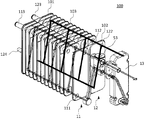
- FIG. 1 is a configuration diagram illustrating an example of a heat exchange unit 100 according to an embodiment of the present disclosure.
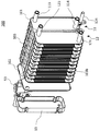
- FIG. 2 is a perspective view of the heat exchange unit 100 shown in FIG. 1 as viewed from the opposite side.
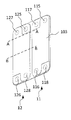
- FIG. 3 is an exploded perspective view of the heat exchange unit 100 shown in FIG. 4 is an exploded perspective view of the heat exchange unit 100 shown in FIG. 3 as viewed from the opposite side.
- the heat exchange unit 100 is a device that performs heat exchange between two kinds of fluids having a temperature difference, cools a high-temperature fluid, and superheats a low-temperature fluid.
- the heat exchange unit 100 is used in a heat pump system such as the vehicle air conditioner 1 described later with reference to FIGS.
- the heat exchange unit 100 includes a first heat exchanger 11, a second heat exchanger 12, and a receiver tank 13.
- coolant heat exchanger 11, the 2nd heat exchanger 12, and the receiver tank 13 are integrated, and are comprised as one unit.
- the first heat exchanger 11 has a flow path for flowing a low-temperature and low-pressure refrigerant and a flow path for flowing a coolant, and when heating operation is performed in the vehicle air conditioner 1 (see FIG. 8) described later. It functions as an evaporator and causes heat exchange between the refrigerant and the coolant. Specifically, in the first heat exchanger 11, the low-temperature and low-pressure refrigerant absorbs heat from the introduced coolant, and the low-temperature and low-pressure refrigerant evaporates.
- a refrigerant pipe extending from the receiver tank 13 communicates with the refrigerant introduction port 111 of the first heat exchanger 11, and an expansion valve 53 is arranged in the middle of the refrigerant pipe.
- the refrigerant outlet 112 of the first heat exchanger 11 communicates with an inlet of a compressor 10 (see FIG. 8) described later via an expansion valve 53 and a refrigerant pipe.
- the second heat exchanger 12 has a flow path for flowing a high-temperature and high-pressure refrigerant discharged from the compressor 10 and a flow path for flowing a coolant, and functions as a condenser to exchange heat between the refrigerant and the coolant. To do. Specifically, in the second heat exchanger 12, heat is transferred from the introduced high-temperature and high-pressure refrigerant to the coolant, and the high-temperature and high-pressure refrigerant is condensed.
- the refrigerant introduction port 124 of the second heat exchanger 12 communicates with the discharge port of the compressor 10 through a refrigerant pipe.
- the refrigerant outlet 122 of the second heat exchanger 12 communicates with the receiver tank 13 as it is.
- the first heat exchanger 11 and the second heat exchanger 12 are configured as an integrated unit. Specifically, in the first heat exchanger 11 and the second heat exchanger 12, a plurality of plates 103 that form flow paths of refrigerant and cooling water are laminated between the plate-like panels 101 and 102. It is formed by. Each plate 103 is a substantially rectangular plate-shaped member formed of a metal having high thermal conductivity, and the first 103 is configured to prevent the fluid from going back and forth directly between the first heat exchanger 11 and the second heat exchanger 12. The flow path in the heat exchanger 11 and the flow path in the second heat exchanger 12 are divided into left and right with the center of each plate as a boundary.
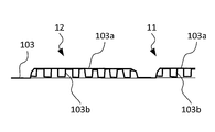
- FIG. 5 is a perspective view showing an example of the plate shown in FIG. 6 is a cross-sectional view of the plate shown in FIG. 5 along the line AA.
- 7 is a cross-sectional view of the plate shown in FIG. 5 taken along the line BB.
- one side (left side in FIG. 5) of the plate 103 is a region constituting the first heat exchanger 11, and the other side (right side in FIG. 5) constitutes the second heat exchanger 12. It becomes an area.
- a concave portion 103a is formed in each of the left and right regions of the plate 103.
- Inner fins 103b formed in a wavy shape are formed in regions other than the upper and lower ends of the concave portion 103a.
- openings 115 and 116 serving as coolant passages and openings 117 and 118 serving as coolant passages are formed on the first heat exchanger 11 side of the plate 103. Yes. Similarly, openings 125 and 126 serving as coolant passages and openings 127 and 128 serving as coolant passages are also formed on the second heat exchanger 12 side of the plate 103.
- an inlet 113 and an outlet 114 for the coolant flowing through the flow path of the first heat exchanger 11 are provided on the surface of one panel 101.
- an inlet 123 and an outlet 121 for the coolant flowing through the flow path of the second heat exchanger 12 are provided.
- a refrigerant inlet 111 and an outlet 112 are provided on the first heat exchanger 11 side of the other panel 102.
- a refrigerant outlet 122 is provided on the second heat exchanger 12 side.
- the panel 101 is provided with many parts such as the coolant inlets 113 and 123, the outlets 114 and 121, and the refrigerant inlet 124 on the surface thereof. It is relatively easy to ensure the strength.
- the receiver tank 13 that temporarily stores the refrigerant is integrally provided in the planar area of the panel 102 on the second heat exchanger 12 side. Specifically, the receiver tank 13 is fixed to a planar area of the panel 102. Thereby, since the wall surface of the panel 102 can be reinforced with the receiver tank 13, the intensity
- the receiver tank 13 has a role of maintaining an appropriate and stable operation of the heat pump cycle by temporarily storing the surplus refrigerant. For this reason, it is important for the receiver tank 13 to have an appropriate volume for stable heat pump operation.
- the receiver tank 13 is provided in a planar area on the second heat exchanger 12 side of the panel 102.
- the receiver tank 13 is provided on the second heat exchanger 12 side of the panel 102, but may be provided on the first heat exchanger 11 side. Moreover, it is good also as providing in the 1st heat exchanger 11 side and the 2nd heat exchanger 12 side of the panel 101.
- the receiver tank 13 is formed in a box shape having an opening on the panel 102 side, and a space for storing refrigerant is formed by the surface of the panel 102 and the receiver tank 13.
- the receiver tank 13 may be box-shaped, and the surface of the receiver tank 13 on the panel 102 side may be fixed to the surface of the panel 102.
- the receiver tank 13 is fixed to the panel 102 by brazing, for example.
- the receiver tank 13 and the panel 102 are formed from a metal such as an aluminum alloy, the receiver tank 13 and the panel 102 can be easily integrated by brazing.
- the receiver tank 13 with a rib (rib structure) that reaches the planar region of the panel 102 from the inner surface of the receiver tank 13, the strength of the region may be further increased.
- the heat exchange unit 100 of the present embodiment is also integrated with the receiver tank 13.
- the receiver tank 13 Is fixed to the planar area of the second heat exchanger 12, whereby the strength of the second heat exchanger 12 can be increased without adding a reinforcing member separately.
- coolant can be ensured easily, without receiving the restriction
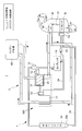
- FIG. 8 is a configuration diagram illustrating an example of a vehicle air conditioner according to an embodiment of the present disclosure.
- This vehicle air conditioner 1 is mounted on a vehicle equipped with an engine (internal combustion engine) 40, which is an example of a heat generating component of the vehicle, and is a device that adjusts air in the passenger compartment.
- the vehicle air conditioner 1 is disposed in an engine room.
- the vehicle air conditioner 1 includes a compressor 10, a heat exchange unit 100, an outdoor condenser 20, a heater core 31, an evaporator 32, an engine 40, a first on-off valve 51, a second on-off valve 52, expansion valves 53 and 54, and a check valve. 55.
- the vehicle air conditioner 1 includes a refrigerant pipe connecting the compressor 10, the outdoor capacitor 20, the expansion valve 54, and the evaporator 32, and a refrigerant pipe connecting the compressor 10 and the heat exchange unit 100.
- a refrigerant circuit 2 is provided.
- the vehicle air conditioner 1 includes a coolant circuit 3 including a coolant pipe connecting the heater core 31, the heat exchange unit 100, and the engine 40.
- the refrigerant pipe connecting the compressor 10 and the heat exchange unit 100 constitutes the heating refrigerant circuit 2 ⁇ / b> A, and connects the compressor 10, the outdoor capacitor 20, the expansion valve 54, and the evaporator 32.
- the piping forms a cooling refrigerant circuit 2B. Note that the refrigerant piping of the refrigerant circuit 2A for heating and the refrigerant circuit 2B for cooling is partially shared on the discharge port side of the compressor 10.
- the engine 40 includes an engine cooling unit.
- the engine cooling unit includes, for example, a water jacket for flowing a coolant around the engine 40 and a pump for flowing the coolant to the water jacket, and discharges exhaust heat from the engine 40 to the coolant flowing in the water jacket.
- the pump is rotated by the power of the engine 40, for example.
- the inlet of the coolant in the engine cooling part of the engine 40 is communicated with the first heat exchanger 11 of the heat exchange unit 100 via the coolant pipe. Further, the coolant outlet of the engine cooling section of the engine 40 is communicated with the second heat exchanger 12 of the heat exchange unit 100 via the coolant pipe.
- the engine cooling unit may be provided with a radiator that releases heat to the outside air when the amount of exhaust heat from the engine 40 increases.
- the cooling liquid is, for example, an antifreeze liquid such as LLC (Long Life Coolant), and is a liquid for transporting heat.
- an antifreeze liquid such as LLC (Long Life Coolant)
- the transfer of the coolant in the coolant circuit 3 can be performed using only the pump provided in the engine cooling unit. Thereby, reduction of the cost of an apparatus and reduction of the installation space of an apparatus can be aimed at.
- a pump may be added to another part of the coolant pipe.
- the compressor 10 is a device that is driven by engine power or electricity, compresses sucked refrigerant, and discharges high-temperature and high-pressure refrigerant.
- the refrigerant compressed by the compressor 10 is sent from the discharge port of the compressor 10 to the outdoor condenser 20 or the second heat exchanger 12 through the refrigerant pipe.
- the low-temperature and low-pressure refrigerant discharged from the first heat exchanger 11 or the evaporator 32 is sucked from the suction port of the compressor 10 through the refrigerant pipe.
- the refrigerant pipe extending from the discharge port of the compressor 10 is divided into a pipe that reaches the refrigerant inlet of the outdoor condenser 20 and a pipe that reaches the refrigerant inlet 124 (see FIG. 2) of the second heat exchanger 12.
- a branching portion for branching is provided.
- the refrigerant flows through the piping extending from the discharge port of the compressor 10 leading to this branching part both during heating and during cooling.
- a first on-off valve 51 capable of blocking the flow of the refrigerant is disposed in the pipe between the branch portion and the refrigerant inlet of the outdoor capacitor 20.
- a second open / close valve 52 capable of blocking the flow of the refrigerant is disposed in the pipe between the branch portion and the refrigerant inlet 124 of the second heat exchanger 12.
- the first on-off valve 51 and the second on-off valve 52 are valves that switch between opening and closing in the middle of the refrigerant pipe, for example, by electrical control.
- pilot valves that are a kind of electromagnetic valves are employed as the first on-off valve 51 and the second on-off valve 52.
- the high-temperature and high-pressure refrigerant discharged from the compressor 10 is sent to the cooling refrigerant circuit 2A including the outdoor capacitor 20, or Whether the refrigerant is sent to the heating refrigerant circuit 2B including the second heat exchanger 12 is selected.
- the second heat exchanger 12 functions as a sub-condenser during heating, exchanges heat between the high-temperature and high-pressure refrigerant and the coolant, and condenses the refrigerant.
- the refrigerant introduction port 124 of the second heat exchanger 12 is communicated with the discharge port of the compressor 10 through the refrigerant pipe of the heating refrigerant circuit 2A.
- the refrigerant outlet 122 of the second heat exchanger 12 communicates with the suction port of the compressor 10 through the expansion valve 53 and the first heat exchanger 11 in order through the refrigerant pipe of the refrigerant circuit 2A for heating. ing.
- the coolant inlet 123 of the second heat exchanger 12 communicates with the engine cooling part of the engine 40 through the coolant pipe.
- the coolant outlet 121 of the second heat exchanger 12 communicates with the heater core 31 via the coolant pipe.
- the first heat exchanger 11 functions as a sub-evaporator during heating, exchanges heat between the low-temperature and low-pressure refrigerant and the coolant, and evaporates the refrigerant.
- the refrigerant inlet 111 of the first heat exchanger 11 communicates with the expansion valve 53 via the refrigerant pipe of the refrigerant circuit 2A for heating.
- the refrigerant outlet 112 of the first heat exchanger 11 communicates with the inlet of the compressor 10 through the refrigerant pipe of the refrigerant circuit 2A for heating.
- the coolant inlet 113 of the first heat exchanger 11 communicates with the heater core 31 via the coolant pipe.
- the coolant outlet 121 of the second heat exchanger 12 communicates with the engine cooling section of the engine 40 via the coolant pipe.
- the expansion valve 53 expands the high-temperature and high-pressure refrigerant and discharges the low-temperature and low-pressure refrigerant to the first heat exchanger 11.
- the expansion valve 53 is disposed in the vicinity of the first heat exchanger 11 immediately upstream of the first heat exchanger 11.
- the expansion valve 53 is, for example, a temperature expansion valve (TXV) that has a function of automatically adjusting the refrigerant flow rate to be discharged according to the temperature of the refrigerant sent from the first heat exchanger 11.
- TXV temperature expansion valve
- the outdoor condenser 20 has a flow path for flowing a high-temperature and high-pressure refrigerant and a flow path for flowing air, and is disposed near the head of the vehicle in the engine room, for example, and performs heat exchange between the refrigerant and the outside air. .
- the high-temperature and high-pressure refrigerant discharged from the compressor 10 flows through the outdoor condenser 20 in the cooling mode described in detail later, and heat is discharged from the refrigerant to the outside air. Outside air is blown onto the outdoor capacitor 20 by, for example, a fan.
- a reservoir tank 20 a may be provided on the refrigerant delivery side of the outdoor capacitor 20.
- the heater core 31 and the evaporator 32 are disposed in an intake passage of an HVAC (Heating, “Ventilation,” and “Air” Conditioning) 30.
- the HVAC 30 is provided with a fan 34 for flowing intake air.
- the heater core 31 is included in the coolant circuit 3, and the evaporator 32 is included in the refrigerant circuit 2.
- the heater core 31 is a device that exchanges heat between the coolant and air, and is disposed in the intake passage of the HVAC 30 that supplies air into the passenger compartment. Heated coolant is supplied to the heater core 31 and releases heat to intake air (air sent to the vehicle interior) sent to the vehicle interior in the heating mode described in detail later.
- the heater core 31 can adjust the amount of air passing through the opening of the door 33 in the intake passage.
- the door 33 can be opened and closed by electrical control, and is also called a mix door.
- the evaporator 32 is a device that exchanges heat between the low-temperature and low-pressure refrigerant and the air, and is disposed in the intake passage of the HVAC 30. In the cooling mode, the evaporator 32 is supplied with a low-temperature and low-pressure refrigerant to cool the intake air (air sent to the vehicle compartment) supplied to the vehicle interior.
- the expansion valve 54 expands the high-pressure refrigerant and discharges the low-temperature and low-pressure refrigerant to the evaporator 32.
- the expansion valve 54 is disposed in the vicinity of the evaporator 32 immediately upstream of the evaporator 32.
- the expansion valve 54 is, for example, a temperature type expansion valve (TXV) having a function of automatically adjusting the refrigerant flow rate to be discharged according to the temperature of the refrigerant sent from the evaporator 32.
- TXV temperature type expansion valve
- a check valve 55 is arranged in the middle of the refrigerant circuit from the evaporator 32 to the compressor 10.
- the check valve 55 is a valve that prevents a reverse flow of the refrigerant in the heating mode in which the refrigerant does not flow to the outdoor condenser 20 and the evaporator 32.
- the refrigerant pressure in the outdoor condenser 20 and the evaporator 32 may be lowered.
- the refrigerant flowing in the refrigerant circuit 2A of the first heat exchanger 11 and the second heat exchanger 12 flows back to the cooling refrigerant circuit 2B on the evaporator 32 side, and the heat pump cycle Efficiency will decrease.
- Such inconvenience can be avoided by the presence of the check valve 55.
- the vehicle air conditioner 1 has a control system configuration in which a compressor 10 is driven, each operating part of the HVAC 30 is driven, the first on-off valve 51 and the second on-off valve 52 are opened and closed, and a pump that transfers cooling liquid by power. Etc. are provided with a control unit (not shown) for controlling the respective components.
- the control unit is, for example, a device including a microcomputer, an IO (Input / Output), a program memory storing a control program, a working memory, and the like, and the microcomputer performs predetermined control according to the control program. It may be configured as, or may be configured from a plurality of units.
- the operation modes of the vehicle air conditioner 1 include a hot water heating mode during heating, a heat pump heating mode, and a cooling mode during cooling.
- the vehicle air conditioner 1 switches between these operation modes.
- the hot water heating mode is a mode in which the passenger compartment is heated without operating the heat pump.
- the heat pump heating mode is a mode in which the vehicle interior is heated by operating the heat pump.
- the cooling mode is a mode in which the passenger compartment is cooled by the action of the heat pump.
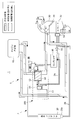
- FIG. 9 is a diagram for explaining the operation in the heat pump heating mode.
- This heating mode is a mode in which the first on-off valve 51 is closed and the second on-off valve 52 is opened. Further, the door 33 of the heater core 31 is opened (for example, fully opened).
- the refrigerant discharged from the compressor 10 passes through the second heat exchanger 12, the expansion valve 53, and the first heat exchanger 11 in order in the heating refrigerant circuit 2A, and returns to the compressor 10. Circulate like so.
- the refrigerant compressed by the compressor 10 dissipates heat to the coolant in the second heat exchanger 12 and condenses.
- the condensed refrigerant is expanded by the expansion valve 53 to become a low-temperature and low-pressure refrigerant, and is sent to the first heat exchanger 11.
- the low-temperature and low-pressure refrigerant absorbs heat from the coolant in the first heat exchanger 11 and evaporates.
- the evaporated low-pressure refrigerant is sucked into the compressor 10 and compressed again.
- the coolant circulates in the coolant circuit 3 so as to pass through the engine 40, the second heat exchanger 12, the heater core 31, and the first heat exchanger 11 in this order.
- the coolant that has absorbed the exhaust heat by the engine 40 is further heated by the second heat exchanger 12 and sent to the heater core 31.
- the coolant that has reached a high temperature can sufficiently heat the intake air that is sent into the passenger compartment by the heater core 31.
- the coolant that has passed through the heater core 31 has a higher temperature than the outside air, and the first heat exchanger 11 can release heat to the refrigerant to evaporate the refrigerant. Further, the coolant cooled by the first heat exchanger 11 is sent to the engine 40 and used for cooling the engine 40.
- Such operation in the heating mode can sufficiently heat the passenger compartment.
- FIG. 10 is a diagram for explaining the operation in the cooling mode.
- the cooling mode is a mode in which the first on-off valve 51 is opened and the second on-off valve 52 is closed. Further, the door 33 of the heater core 31 is fully closed.
- the refrigerant discharged from the compressor 10 circulates back to the compressor 10 through the outdoor condenser 20, the expansion valve 54, and the evaporator 32 in this order in the cooling refrigerant circuit 2B.
- the high-temperature and high-pressure refrigerant compressed by the compressor 10 dissipates heat to the air by the outdoor condenser 20 and condenses.
- the condensed refrigerant expands in the expansion valve 54 to become a low-temperature and low-pressure refrigerant and is sent to the evaporator 32.
- the low-temperature and low-pressure refrigerant is evaporated by the evaporator 32 by cooling the intake air sent to the passenger compartment.
- the evaporated low-pressure refrigerant is sucked into the compressor 10 and compressed.
- the flow of the coolant is the same as in the heating mode, and circulates in the coolant circuit 3 so as to pass through the engine 40, the second heat exchanger 12, the heater core 31, and the first heat exchanger 11 in order. To do.
- the coolant passes through the second heat exchanger 12, the heater core 31, and the first heat exchanger 11 in this order, it hardly exchanges heat with the refrigerant or air.
- the heat radiation of the coolant is mainly performed by a radiator of an engine cooling unit in the engine 40.
- the engine 40 Since the engine 40 is very hot, it is cooled by heat dissipation from the radiator even if the outside air temperature is high. Here, it is good also as employ
- the vehicle air conditioner 1 uses the configuration of the hot water heater that uses the coolant of the engine 40 to flow through the heater core 31 for heating and the low-temperature and low-pressure refrigerant of the heat pump. It also has a heat pump type cooling device that performs cooling as a basic configuration. And the heat exchange unit 100 is added to this basic structure, and it becomes the structure which can heat the vehicle interior using a heat pump. With such a configuration, even when the engine 40 is at a low temperature, the vehicle interior can be quickly heated with a small amount of energy by the action of the heat pump.
- the basic structure is the same as that of a hot water heater and a heat pump type cooling device as used in a conventional vehicle, and at the time of cooling and heating.
- the common compressor 10 and the refrigerant By using the common compressor 10 and the refrigerant, the heating performance can be improved at a low cost, and the increase in installation space can be reduced from the conventional configuration.
- the embodiments of the present disclosure have been described with reference to the drawings.
- the specific configuration is not limited to these embodiments, and the present disclosure may be modified or added without departing from the scope of the present disclosure.
- the heat exchange unit 100 of the present disclosure is not limited to the vehicle air conditioner 1 described in the embodiment, and can be used in various devices.
- the heat exchange unit 100 is 2nd heat.
- a configuration in which the exchanger 12 and the receiver tank 13 are integrated and the first heat exchanger 11 is provided separately may be employed.
- Such a heat exchange unit 100 can be applied to a hot gas cycle, for example.
- the present disclosure can be used for a vehicle air conditioner mounted on various vehicles such as an engine vehicle, an electric vehicle, or an HEV vehicle, and its heat exchange unit.
Abstract
This heat exchanging unit is provided with: a heat exchanger that is configured by sandwiching multiple plates between two panels and that performs a heat exchange between a cooling liquid, for cooling a heat generation component, and an air conditioning coolant flowing between the plates; and a tank that stores therein the coolant. The heat exchanger and the tank are integrated with each other, and the tank is fixed in a region of a surface of either of the two panels.
Description
本開示は、熱交換ユニットおよび車両用空調装置に関する。
This disclosure relates to a heat exchange unit and a vehicle air conditioner.
車両用エアコンシステムは、冷媒を吸入/圧縮し高圧にする圧縮機(コンプレッサ)と、その高圧冷媒を他の媒体(一般的には空気)と熱交換して冷却して冷媒を液化する凝縮器(コンデンサ)と、その液化した冷媒を溜め込むレシーバーと、その冷媒を断熱膨張させ、冷媒を低圧、低温にする膨張弁と、その冷媒を他の媒体(一般的には空気)と熱交換して冷媒を気化させる蒸発器(エバポレータ)と、それらを繋ぐ配管とで閉回路を形成している。
A vehicle air conditioner system includes a compressor (compressor) that sucks / compresses refrigerant to generate a high pressure, and a condenser that liquefies the refrigerant by exchanging heat with the other medium (generally air). (Condenser), a receiver that stores the liquefied refrigerant, an expansion valve that adiabatically expands the refrigerant to make the refrigerant low pressure and low temperature, and heat exchange of the refrigerant with another medium (generally air) A closed circuit is formed by an evaporator (evaporator) for vaporizing the refrigerant and a pipe connecting them.
例えば、特許文献1には、ラジエータと連結されて冷却水を循環させるとともに、コンプレッサにより吐出された冷媒を循環させ、冷却水と冷媒との間の熱交換により冷媒を凝縮させる第1放熱部と、第1放熱部により冷却され、凝縮した冷媒を2次冷却する第2放熱部と、冷媒の気液分離を行い、さらに凝縮した冷媒から水分を除去するレシーバドライバ部とが一体形成された車両用コンデンサが開示されている。ここで、レシーバドライバ部は、液冷媒を貯留して、循環する冷媒の量を調整する役割も果たしている。
For example, Patent Document 1 discloses a first heat radiating unit that is connected to a radiator to circulate cooling water, circulates refrigerant discharged by a compressor, and condenses the refrigerant by heat exchange between the cooling water and the refrigerant. A vehicle in which a second heat dissipating part that cools the condensed refrigerant that has been cooled and condensed by the first heat dissipating part and a receiver driver part that performs gas-liquid separation of the refrigerant and further removes moisture from the condensed refrigerant are integrally formed. A capacitor is disclosed. Here, the receiver driver unit also plays a role of storing the liquid refrigerant and adjusting the amount of the circulating refrigerant.
本開示の一態様に係る熱交換ユニットは、2つのパネルに複数のプレートを挟んで構成され、プレート間を流れる空調用の冷媒と発熱部品を冷却する冷却液との間で熱交換を行う熱交換器と、冷媒を貯留するタンクと、を具備し、熱交換器、および、タンクは一体化されており、タンクは、2つのパネルの何れかのパネルの面上の領域に固着されている。
A heat exchange unit according to an aspect of the present disclosure is configured by sandwiching a plurality of plates between two panels, and performs heat exchange between an air-conditioning refrigerant flowing between the plates and a coolant that cools a heat-generating component. The heat exchanger and the tank are integrated, and the tank is fixed to a region on the surface of one of the two panels. .
また、本開示の一態様に係る車両用空調装置は、冷媒を圧縮するコンプレッサと、圧縮された冷媒との熱交換により温められた冷却液により車室内に送られる空気を加熱するヒーターコアと、2つのパネルに複数のプレートを挟んで構成され、プレート間を流れる空調用の冷媒と発熱部品を冷却する冷却液との間で熱交換を行う熱交換器と、冷媒を貯留するタンクと、を具備し、熱交換器、および、タンクは一体化されており、タンクは、2つのパネルの何れかのパネルの面上の領域に固着されている。
In addition, a vehicle air conditioner according to an aspect of the present disclosure includes a compressor that compresses a refrigerant, a heater core that heats air that is sent into the vehicle interior by a coolant that is warmed by heat exchange with the compressed refrigerant, A heat exchanger configured by sandwiching a plurality of plates between two panels and performing heat exchange between a refrigerant for air conditioning flowing between the plates and a coolant for cooling the heat generating component; and a tank for storing the refrigerant. The heat exchanger and the tank are integrated, and the tank is fixed to a region on the surface of one of the two panels.
本開示の熱交換ユニットおよび車両用空調装置によれば、冷媒の貯留に必要な容積を容易に確保することができ、貯留容積の変更も容易にでき、さらに十分な強度を確保することができる。
According to the heat exchange unit and the vehicle air conditioner of the present disclosure, it is possible to easily secure the volume necessary for storing the refrigerant, to easily change the stored volume, and to secure sufficient strength. .
本開示の実施の形態の説明に先立ち、従来における問題点を簡単に説明する。特許文献1に開示の技術では、レシーバドライバ部は、複数のプレートが積層されて構成された車両用コンデンサ内に形成されるため、車両用コンデンサに要求される性能および車両用コンデンサにおける各構成部の配置の制限によりレシーバドライバ部が貯留できる冷媒の量の範囲が決定されてしまう。
Prior to the description of the embodiment of the present disclosure, the conventional problems will be briefly described. In the technique disclosed in Patent Document 1, since the receiver driver unit is formed in a vehicle capacitor formed by stacking a plurality of plates, the performance required for the vehicle capacitor and each component in the vehicle capacitor The range of the amount of refrigerant that can be stored in the receiver driver unit is determined by the restriction on the arrangement of the receiver.
そのため、レシーバドライバ部にヒートサイクルを適正に稼働させるための十分な量の冷媒を確保することは困難であった。また、レシーバドライバ部における冷媒の貯留量を変更しようとすると、冷媒を貯留する部分だけでなく、車両用コンデンサ全体を設計し直す必要もあった。
Therefore, it was difficult to secure a sufficient amount of refrigerant for operating the heat cycle properly in the receiver driver section. In addition, when attempting to change the amount of refrigerant stored in the receiver driver unit, it is necessary to redesign the entire vehicle capacitor, not just the part storing the refrigerant.
さらに、複数のプレートが積層された構成のコンデンサでは、最も外側のプレートは内側にあるプレートよりも膨張した冷媒の圧力により破損する危険性があり、この危険性を減らしたいという要望もあった。
Furthermore, in a capacitor having a structure in which a plurality of plates are stacked, the outermost plate has a risk of being damaged by the pressure of the expanded refrigerant as compared with the inner plate, and there is a demand for reducing this risk.
本開示の目的は、冷媒の貯留に必要な容積を容易に確保することができ、貯留容積の変更も容易にでき、さらに十分な強度を確保することができる熱交換ユニットおよびその熱交換器ユニットを備える車両用空調装置を提供することである。
An object of the present disclosure is to provide a heat exchange unit that can easily secure a volume required for storing refrigerant, can easily change the stored volume, and can secure sufficient strength, and a heat exchanger unit thereof. It is providing a vehicle air conditioner provided with these.
以下、本開示の実施の形態について図面を参照して詳細に説明する。図1は、本開示の実施の形態の熱交換ユニット100の一例を示す構成図である。図2は、図1に示した熱交換ユニット100を反対側から見た斜視図である。図3は、図1に示した熱交換ユニット100の分解斜視図である。図4は、図3に示した熱交換ユニット100を反対側から見た分解斜視図である。
Hereinafter, embodiments of the present disclosure will be described in detail with reference to the drawings. FIG. 1 is a configuration diagram illustrating an example of a heat exchange unit 100 according to an embodiment of the present disclosure. FIG. 2 is a perspective view of the heat exchange unit 100 shown in FIG. 1 as viewed from the opposite side. FIG. 3 is an exploded perspective view of the heat exchange unit 100 shown in FIG. 4 is an exploded perspective view of the heat exchange unit 100 shown in FIG. 3 as viewed from the opposite side.
本開示の実施の形態の熱交換ユニット100は、温度差のある2種類の流体間で熱交換を行い、高温流体の冷却や低温流体の過熱を行う装置である。例えば、熱交換ユニット100は、後に図8~10を用いて説明する車両用空調装置1などのヒートポンプシステムに用いられる。
The heat exchange unit 100 according to the embodiment of the present disclosure is a device that performs heat exchange between two kinds of fluids having a temperature difference, cools a high-temperature fluid, and superheats a low-temperature fluid. For example, the heat exchange unit 100 is used in a heat pump system such as the vehicle air conditioner 1 described later with reference to FIGS.
図1、図2に示すように、熱交換ユニット100は、第1熱交換器11、および、第2熱交換器12と、レシーバタンク13を備えている。第1水冷媒熱交換器11、第2熱交換器12、および、レシーバタンク13は一体化されており、一つのユニットとして構成されている。
As shown in FIGS. 1 and 2, the heat exchange unit 100 includes a first heat exchanger 11, a second heat exchanger 12, and a receiver tank 13. The 1st water refrigerant | coolant heat exchanger 11, the 2nd heat exchanger 12, and the receiver tank 13 are integrated, and are comprised as one unit.
第1熱交換器11は、低温低圧の冷媒を流す流路と、冷却液を流す流路とを有し、後述する車両用空調装置1(図8を参照)において暖房運転がなされる場合にエバポレータとして機能して冷媒と冷却液との間で熱交換を行わせる。具体的には、第1熱交換器11では、導入された冷却液から低温低圧の冷媒が熱を吸熱し、低温低圧の冷媒が蒸発する。
The first heat exchanger 11 has a flow path for flowing a low-temperature and low-pressure refrigerant and a flow path for flowing a coolant, and when heating operation is performed in the vehicle air conditioner 1 (see FIG. 8) described later. It functions as an evaporator and causes heat exchange between the refrigerant and the coolant. Specifically, in the first heat exchanger 11, the low-temperature and low-pressure refrigerant absorbs heat from the introduced coolant, and the low-temperature and low-pressure refrigerant evaporates.
図3、図4に示すように、第1熱交換器11の冷媒導入口111には、レシーバタンク13から延びる冷媒配管が連通しており、冷媒配管の途中には膨張弁53が配置されている。一方、第1熱交換器11の冷媒送出口112は、膨張弁53と冷媒配管を介して後述するコンプレッサ10(図8を参照)の吸入口に連通している。
As shown in FIGS. 3 and 4, a refrigerant pipe extending from the receiver tank 13 communicates with the refrigerant introduction port 111 of the first heat exchanger 11, and an expansion valve 53 is arranged in the middle of the refrigerant pipe. Yes. On the other hand, the refrigerant outlet 112 of the first heat exchanger 11 communicates with an inlet of a compressor 10 (see FIG. 8) described later via an expansion valve 53 and a refrigerant pipe.
第2熱交換器12は、コンプレッサ10から吐出された高温高圧の冷媒を流す流路と、冷却液を流す流路とを有し、コンデンサとして機能して冷媒と冷却液との間で熱交換を行わせる。具体的には、第2熱交換器12では、導入された高温高圧の冷媒から冷却液に熱が移動し、高温高圧の冷媒が凝縮する。
The second heat exchanger 12 has a flow path for flowing a high-temperature and high-pressure refrigerant discharged from the compressor 10 and a flow path for flowing a coolant, and functions as a condenser to exchange heat between the refrigerant and the coolant. To do. Specifically, in the second heat exchanger 12, heat is transferred from the introduced high-temperature and high-pressure refrigerant to the coolant, and the high-temperature and high-pressure refrigerant is condensed.
第2熱交換器12の冷媒導入口124は、冷媒配管を介してコンプレッサ10の吐出口に連通している。一方、第2熱交換器12の冷媒送出口122は、そのままレシーバタンク13の内部に連通している。
The refrigerant introduction port 124 of the second heat exchanger 12 communicates with the discharge port of the compressor 10 through a refrigerant pipe. On the other hand, the refrigerant outlet 122 of the second heat exchanger 12 communicates with the receiver tank 13 as it is.
第1熱交換器11、および、第2熱交換器12は、一体化されたユニットとして構成されている。具体的には、第1熱交換器11と第2熱交換器12とは、板状のパネル101,102の間に、冷媒および冷却水の流路を形成する複数のプレート103が積層されることにより形成されている。各プレート103は、熱伝導率の高い金属により形成された略長方形の板状部材であり、流体が第1熱交換器11と第2熱交換器12の間で直接行き来しないように、第1熱交換器11内の流路と第2熱交換器12内の流路とが各プレートの中央を境にして左右に区分けされている。
The first heat exchanger 11 and the second heat exchanger 12 are configured as an integrated unit. Specifically, in the first heat exchanger 11 and the second heat exchanger 12, a plurality of plates 103 that form flow paths of refrigerant and cooling water are laminated between the plate- like panels 101 and 102. It is formed by. Each plate 103 is a substantially rectangular plate-shaped member formed of a metal having high thermal conductivity, and the first 103 is configured to prevent the fluid from going back and forth directly between the first heat exchanger 11 and the second heat exchanger 12. The flow path in the heat exchanger 11 and the flow path in the second heat exchanger 12 are divided into left and right with the center of each plate as a boundary.
図5は、図3に示したプレートの一例を示す斜視図である。図6は、図5に示したプレートのA-A線断面図である。図7は、図5に示したプレートのB-B線断面図である。
FIG. 5 is a perspective view showing an example of the plate shown in FIG. 6 is a cross-sectional view of the plate shown in FIG. 5 along the line AA. 7 is a cross-sectional view of the plate shown in FIG. 5 taken along the line BB.
図5に示すように、プレート103の片側(図5の左側)が第1熱交換器11を構成する領域となり、もう一方の側(図5の右側)が第2熱交換器12を構成する領域となる。
As shown in FIG. 5, one side (left side in FIG. 5) of the plate 103 is a region constituting the first heat exchanger 11, and the other side (right side in FIG. 5) constitutes the second heat exchanger 12. It becomes an area.
また、図6、図7に示すように、プレート103の左右の各領域には凹部103aが形成されており、凹部103aの上端、下端を除く領域には、波状に成形されたインナーフィン103bが配置されている。そして、隣接するプレート103の凹部103aに冷媒と冷却液とがそれぞれ流れ、冷媒と冷却液との間で熱交換がなされる。
Further, as shown in FIGS. 6 and 7, a concave portion 103a is formed in each of the left and right regions of the plate 103. Inner fins 103b formed in a wavy shape are formed in regions other than the upper and lower ends of the concave portion 103a. Has been placed. Then, the refrigerant and the coolant flow in the recesses 103a of the adjacent plates 103, respectively, and heat exchange is performed between the refrigerant and the coolant.
また、図5に示すように、プレート103における第1熱交換器11側には、冷却液の通路となる開口部115,116、および、冷媒の通路となる開口部117,118が形成されている。同様に、プレート103における第2熱交換器12側にも、冷却液の通路となる開口部125,126、および、冷媒の通路となる開口部127,128が形成されている。
Further, as shown in FIG. 5, openings 115 and 116 serving as coolant passages and openings 117 and 118 serving as coolant passages are formed on the first heat exchanger 11 side of the plate 103. Yes. Similarly, openings 125 and 126 serving as coolant passages and openings 127 and 128 serving as coolant passages are also formed on the second heat exchanger 12 side of the plate 103.
そして、図2に示すように、一方のパネル101の表面には、第1熱交換器11の流路を流れる冷却液の導入口113と送出口114が設けられている。また、第2熱交換器12側には、前述の冷媒導入口124のほか、第2熱交換器12の流路を流れる冷却液の導入口123と送出口121が設けられている。
As shown in FIG. 2, an inlet 113 and an outlet 114 for the coolant flowing through the flow path of the first heat exchanger 11 are provided on the surface of one panel 101. On the second heat exchanger 12 side, in addition to the refrigerant inlet 124 described above, an inlet 123 and an outlet 121 for the coolant flowing through the flow path of the second heat exchanger 12 are provided.
また、図3に示すように、他方のパネル102における第1熱交換器11側には、冷媒の導入口111および送出口112が設けられている。また、第2熱交換器12側には、冷媒の送出口122が設けられている。
Further, as shown in FIG. 3, a refrigerant inlet 111 and an outlet 112 are provided on the first heat exchanger 11 side of the other panel 102. A refrigerant outlet 122 is provided on the second heat exchanger 12 side.
ここで、図4に示すように、パネル101には、その表面に冷却液の導入口113,123、送出口114,121、および、冷媒導入口124などの部品が多く設けられていることから、強度を確保することが比較的容易である。
Here, as shown in FIG. 4, the panel 101 is provided with many parts such as the coolant inlets 113 and 123, the outlets 114 and 121, and the refrigerant inlet 124 on the surface thereof. It is relatively easy to ensure the strength.
一方、パネル102については、第1熱交換器11側には冷媒を導入するための部品が多く設けられているものの、第2熱交換器12側に設けられる部品の数は少ない。そのため、パネル102の第2熱交換器12側の面状の領域に、冷媒を一時的に貯留するレシーバタンク13が一体化して設けられている。具体的には、レシーバタンク13がパネル102の面状の領域に固着されている。これにより、パネル102の壁面をレシーバタンク13で補強することができるので、パネル102の強度を確保することができる。
On the other hand, regarding the panel 102, although many parts for introducing the refrigerant are provided on the first heat exchanger 11 side, the number of parts provided on the second heat exchanger 12 side is small. Therefore, the receiver tank 13 that temporarily stores the refrigerant is integrally provided in the planar area of the panel 102 on the second heat exchanger 12 side. Specifically, the receiver tank 13 is fixed to a planar area of the panel 102. Thereby, since the wall surface of the panel 102 can be reinforced with the receiver tank 13, the intensity | strength of the panel 102 is securable.
また、後に図8~10を用いて説明する車両用空調装置1などのヒートポンプシステムでは、負荷変動に対する冷媒密度の違いにより余剰冷媒が発生する。レシーバタンク13は、この余剰冷媒を一時的に貯留することにより、適正で安定したヒートポンプサイクルの稼働を保つ役割を担っている。そのため、レシーバタンク13の容積を適正にすることが、安定的なヒートポンプの運転を行う上で重要である。
Further, in a heat pump system such as the vehicle air conditioner 1 described later with reference to FIGS. 8 to 10, surplus refrigerant is generated due to a difference in refrigerant density with respect to load fluctuation. The receiver tank 13 has a role of maintaining an appropriate and stable operation of the heat pump cycle by temporarily storing the surplus refrigerant. For this reason, it is important for the receiver tank 13 to have an appropriate volume for stable heat pump operation.
そこで前述のように、この熱交換ユニット100では、レシーバタンク13をパネル102の第2熱交換器12側の面状の領域に設けることとする。これにより、熱交換ユニット100に要求される性能および熱交換ユニット100における各構成部の配置の制限をあまり受けることなく、冷媒の貯留に必要な容積を容易に確保することができ、貯留容積の変更も容易にできる。
Therefore, as described above, in the heat exchange unit 100, the receiver tank 13 is provided in a planar area on the second heat exchanger 12 side of the panel 102. Thereby, the volume required for storage of a refrigerant | coolant can be ensured easily, without receiving the restriction | limiting of the performance requested | required of the heat exchange unit 100, and arrangement | positioning of each structure part in the heat exchange unit 100 so much. Changes can be made easily.
なお、ここでは、パネル102の強度を確保するため、レシーバタンク13をパネル102の第2熱交換器12側に設けることとしたが、第1熱交換器11側に設けることとしてもよい。また、パネル101の第1熱交換器11側および第2熱交換器12側に設けることとしてもよい。
Here, in order to ensure the strength of the panel 102, the receiver tank 13 is provided on the second heat exchanger 12 side of the panel 102, but may be provided on the first heat exchanger 11 side. Moreover, it is good also as providing in the 1st heat exchanger 11 side and the 2nd heat exchanger 12 side of the panel 101. FIG.
また、図4に示すように、レシーバタンク13は、パネル102側が開口した箱型に形成されており、パネル102の表面とレシーバタンク13により冷媒が貯留される空間が形成される。なお、パネル102の補強をさらに強固に行うため、レシーバタンク13を箱型とし、レシーバタンク13のパネル102側の面をパネル102の表面に固着することとしてもよい。
Further, as shown in FIG. 4, the receiver tank 13 is formed in a box shape having an opening on the panel 102 side, and a space for storing refrigerant is formed by the surface of the panel 102 and the receiver tank 13. In order to reinforce the panel 102 more firmly, the receiver tank 13 may be box-shaped, and the surface of the receiver tank 13 on the panel 102 side may be fixed to the surface of the panel 102.
ここで、パネル102に対するレシーバタンク13の固着は、例えばロウ付けにより行われる。特に、レシーバタンク13やパネル102がアルミニウム合金等の金属から成形される場合、レシーバタンク13とパネル102とをロウ付けにより容易に一体化させることができる。
Here, the receiver tank 13 is fixed to the panel 102 by brazing, for example. In particular, when the receiver tank 13 and the panel 102 are formed from a metal such as an aluminum alloy, the receiver tank 13 and the panel 102 can be easily integrated by brazing.
この場合、パネル102の強度が弱い部分にレシーバタンク13の側壁が接合されるようにすると、パネル102の強度を効果的に高めることができる。
In this case, if the side wall of the receiver tank 13 is joined to a portion where the strength of the panel 102 is weak, the strength of the panel 102 can be effectively increased.
さらに、レシーバタンク13に、レシーバタンク13の内面からパネル102の面状の領域に達するリブ(リブ構造)を設けることにより当該領域の強度をさらに高めることとしてもよい。
Furthermore, by providing the receiver tank 13 with a rib (rib structure) that reaches the planar region of the panel 102 from the inner surface of the receiver tank 13, the strength of the region may be further increased.
以上のように、本実施の形態の熱交換ユニット100は、第1熱交換器11、および、第2熱交換器12に加えて、レシーバタンク13も一体化されており、特に、レシーバタンク13が第2熱交換器12の面状の領域に固着されることにより、補強部材を別途追加することなく、第2熱交換器12の強度を高めることができる。
As described above, in addition to the first heat exchanger 11 and the second heat exchanger 12, the heat exchange unit 100 of the present embodiment is also integrated with the receiver tank 13. In particular, the receiver tank 13 Is fixed to the planar area of the second heat exchanger 12, whereby the strength of the second heat exchanger 12 can be increased without adding a reinforcing member separately.
また、熱交換ユニット100に要求される性能および熱交換ユニット100における各構成部の配置の制限をあまり受けることなく、冷媒の貯留に必要な容積を容易に確保することができ、貯留容積の変更も容易にできる。
Moreover, the volume required for storage of a refrigerant | coolant can be ensured easily, without receiving the restriction | limiting of arrangement | positioning of each structure part in the heat exchange unit 100, and the performance requested | required of the heat exchange unit 100, and change of a storage volume Can also be easily done.
次に、熱交換ユニット100を備えた車両用空調装置1について説明する。図8は、本開示の実施の形態に係る車両用空調装置の一例を示す構成図である。
Next, the vehicle air conditioner 1 provided with the heat exchange unit 100 will be described. FIG. 8 is a configuration diagram illustrating an example of a vehicle air conditioner according to an embodiment of the present disclosure.
この車両用空調装置1は、車両の発熱部品の一例であるエンジン(内燃機関)40を備えた車両に搭載されて、車室内の空気調整を行う装置である。車両用空調装置1は、エンジンルーム内に配置されている。
This vehicle air conditioner 1 is mounted on a vehicle equipped with an engine (internal combustion engine) 40, which is an example of a heat generating component of the vehicle, and is a device that adjusts air in the passenger compartment. The vehicle air conditioner 1 is disposed in an engine room.
車両用空調装置1は、コンプレッサ10、熱交換ユニット100、室外コンデンサ20、ヒーターコア31、エバポレータ32、エンジン40、第1開閉弁51,第2開閉弁52、膨張弁53,54、逆止弁55を具備する。
The vehicle air conditioner 1 includes a compressor 10, a heat exchange unit 100, an outdoor condenser 20, a heater core 31, an evaporator 32, an engine 40, a first on-off valve 51, a second on-off valve 52, expansion valves 53 and 54, and a check valve. 55.
また、車両用空調装置1は、コンプレッサ10、室外コンデンサ20、膨張弁54、および、エバポレータ32の間を結ぶ冷媒配管と、コンプレッサ10、および、熱交換ユニット100の間を結ぶ冷媒配管とからなる冷媒回路2を具備する。さらに、車両用空調装置1は、ヒーターコア31、熱交換ユニット100、エンジン40の間を結ぶ冷却液配管からなる冷却液回路3を具備する。
The vehicle air conditioner 1 includes a refrigerant pipe connecting the compressor 10, the outdoor capacitor 20, the expansion valve 54, and the evaporator 32, and a refrigerant pipe connecting the compressor 10 and the heat exchange unit 100. A refrigerant circuit 2 is provided. Further, the vehicle air conditioner 1 includes a coolant circuit 3 including a coolant pipe connecting the heater core 31, the heat exchange unit 100, and the engine 40.
冷媒回路2のうち、コンプレッサ10、熱交換ユニット100の間を結ぶ冷媒配管は、暖房用の冷媒回路2Aをなし、コンプレッサ10、室外コンデンサ20、膨張弁54、および、エバポレータ32の間を結ぶ冷媒配管は、冷房用の冷媒回路2Bをなしている。なお、暖房用の冷媒回路2Aおよび冷房用の冷媒回路2Bの冷媒配管は、コンプレッサ10の吐出口側において一部共通化されている。
Of the refrigerant circuit 2, the refrigerant pipe connecting the compressor 10 and the heat exchange unit 100 constitutes the heating refrigerant circuit 2 </ b> A, and connects the compressor 10, the outdoor capacitor 20, the expansion valve 54, and the evaporator 32. The piping forms a cooling refrigerant circuit 2B. Note that the refrigerant piping of the refrigerant circuit 2A for heating and the refrigerant circuit 2B for cooling is partially shared on the discharge port side of the compressor 10.
エンジン40は、エンジン冷却部を備えている。エンジン冷却部は、例えば、エンジン40の周囲に冷却液を流すウォータジャケットと、ウォータジャケットに冷却液を流すポンプとを具備し、ウォータジャケットに流れる冷却液にエンジン40から排熱を放出させる。ポンプは、例えば、エンジン40の動力により回転する。
The engine 40 includes an engine cooling unit. The engine cooling unit includes, for example, a water jacket for flowing a coolant around the engine 40 and a pump for flowing the coolant to the water jacket, and discharges exhaust heat from the engine 40 to the coolant flowing in the water jacket. The pump is rotated by the power of the engine 40, for example.
エンジン40のエンジン冷却部における冷却液の導入口は、冷却液配管を介して熱交換ユニット100の第1熱交換器11に連通されている。また、エンジン40のエンジン冷却部における冷却液の送出口は、冷却液配管を介して熱交換ユニット100の第2熱交換器12に連通されている。なお、エンジン冷却部には、エンジン40の排熱量が多くなった場合に、熱を外気に放出するラジエータが備わっていてもよい。
The inlet of the coolant in the engine cooling part of the engine 40 is communicated with the first heat exchanger 11 of the heat exchange unit 100 via the coolant pipe. Further, the coolant outlet of the engine cooling section of the engine 40 is communicated with the second heat exchanger 12 of the heat exchange unit 100 via the coolant pipe. The engine cooling unit may be provided with a radiator that releases heat to the outside air when the amount of exhaust heat from the engine 40 increases.
冷却液は、例えば、LLC(Long Life Coolant)等の不凍液であり、熱を輸送するための液体である。ここで、冷却液回路3における冷却液の移送は、エンジン冷却部が備えるポンプのみを用いて行うことができる。これにより、装置のコストの低減および装置の設置スペースの縮小を図ることができる。なお、冷却液の移送能力を高めるために、冷却液配管の他の箇所にポンプを追加してもよい。
The cooling liquid is, for example, an antifreeze liquid such as LLC (Long Life Coolant), and is a liquid for transporting heat. Here, the transfer of the coolant in the coolant circuit 3 can be performed using only the pump provided in the engine cooling unit. Thereby, reduction of the cost of an apparatus and reduction of the installation space of an apparatus can be aimed at. In addition, in order to improve the transfer capability of the coolant, a pump may be added to another part of the coolant pipe.
コンプレッサ10は、エンジンの動力または電気により駆動して、吸入した冷媒を圧縮し、高温高圧の冷媒を吐出する装置である。コンプレッサ10で圧縮された冷媒は、コンプレッサ10の吐出口より冷媒配管を通って室外コンデンサ20、または、第2熱交換器12へ送られる。
The compressor 10 is a device that is driven by engine power or electricity, compresses sucked refrigerant, and discharges high-temperature and high-pressure refrigerant. The refrigerant compressed by the compressor 10 is sent from the discharge port of the compressor 10 to the outdoor condenser 20 or the second heat exchanger 12 through the refrigerant pipe.
また、第1熱交換器11、または、エバポレータ32から吐出される低温低圧の冷媒は、冷媒配管を通ってコンプレッサ10の吸入口から吸入される。
Further, the low-temperature and low-pressure refrigerant discharged from the first heat exchanger 11 or the evaporator 32 is sucked from the suction port of the compressor 10 through the refrigerant pipe.
コンプレッサ10の吐出口から延びる冷媒配管は、途中で室外コンデンサ20の冷媒導入口に至る配管と、第2熱交換器12の冷媒導入口124(図2を参照)に至る配管とに冷媒配管を分岐させる分岐部が設けられている。
The refrigerant pipe extending from the discharge port of the compressor 10 is divided into a pipe that reaches the refrigerant inlet of the outdoor condenser 20 and a pipe that reaches the refrigerant inlet 124 (see FIG. 2) of the second heat exchanger 12. A branching portion for branching is provided.
この分岐部に至るコンプレッサ10の吐出口から延びる配管には、暖房時にも冷房時にも冷媒が流れる。そして、上記分岐部と室外コンデンサ20の冷媒導入口との間の配管には、冷媒の流れを遮断可能な第1開閉弁51が配置されている。一方、上記分岐部と第2熱交換器12の冷媒導入口124との間の配管には、冷媒の流れを遮断可能な第2開閉弁52が配置されている。
The refrigerant flows through the piping extending from the discharge port of the compressor 10 leading to this branching part both during heating and during cooling. A first on-off valve 51 capable of blocking the flow of the refrigerant is disposed in the pipe between the branch portion and the refrigerant inlet of the outdoor capacitor 20. On the other hand, a second open / close valve 52 capable of blocking the flow of the refrigerant is disposed in the pipe between the branch portion and the refrigerant inlet 124 of the second heat exchanger 12.
第1開閉弁51および第2開閉弁52は、例えば、電気的な制御により、冷媒配管の途中で開閉を切り替える弁である。例えば、第1開閉弁51および第2開閉弁52として、電磁弁の一種であるパイロット式弁が採用される。
The first on-off valve 51 and the second on-off valve 52 are valves that switch between opening and closing in the middle of the refrigerant pipe, for example, by electrical control. For example, as the first on-off valve 51 and the second on-off valve 52, pilot valves that are a kind of electromagnetic valves are employed.
そして、第1開閉弁51および第2開閉弁52の開閉の切り替え制御により、コンプレッサ10から吐出された高温高圧の冷媒が、室外コンデンサ20を含む冷房用の冷媒回路2Aに送出されるのか、または、第2熱交換器12を含む暖房用の冷媒回路2Bに送出されるのかが選択される。
Then, by switching control of opening and closing of the first on-off valve 51 and the second on-off valve 52, the high-temperature and high-pressure refrigerant discharged from the compressor 10 is sent to the cooling refrigerant circuit 2A including the outdoor capacitor 20, or Whether the refrigerant is sent to the heating refrigerant circuit 2B including the second heat exchanger 12 is selected.
第2熱交換器12は、暖房時にサブコンデンサとして機能し、高温高圧の冷媒と冷却液との間で熱交換を行い、冷媒を凝縮させる。第2熱交換器12の冷媒導入口124は、暖房用の冷媒回路2Aの冷媒配管を介してコンプレッサ10の吐出口に連通されている。一方、第2熱交換器12の冷媒送出口122は、同じく暖房用の冷媒回路2Aの冷媒配管を介して、膨張弁53および第1熱交換器11を順に経てコンプレッサ10の吸入口に連通している。
The second heat exchanger 12 functions as a sub-condenser during heating, exchanges heat between the high-temperature and high-pressure refrigerant and the coolant, and condenses the refrigerant. The refrigerant introduction port 124 of the second heat exchanger 12 is communicated with the discharge port of the compressor 10 through the refrigerant pipe of the heating refrigerant circuit 2A. On the other hand, the refrigerant outlet 122 of the second heat exchanger 12 communicates with the suction port of the compressor 10 through the expansion valve 53 and the first heat exchanger 11 in order through the refrigerant pipe of the refrigerant circuit 2A for heating. ing.
また、冷却液回路3においては、第2熱交換器12の冷却液の導入口123は、冷却液配管を介してエンジン40のエンジン冷却部に連通している。一方、第2熱交換器12の冷却液の送出口121は、冷却液配管を介してヒーターコア31に連通している。
Further, in the coolant circuit 3, the coolant inlet 123 of the second heat exchanger 12 communicates with the engine cooling part of the engine 40 through the coolant pipe. On the other hand, the coolant outlet 121 of the second heat exchanger 12 communicates with the heater core 31 via the coolant pipe.
第1熱交換器11は、暖房時にサブエバポレータとして機能し、低温低圧の冷媒と冷却液との間で熱交換を行い、冷媒を蒸発させる。第1熱交換器11の冷媒導入口111は、暖房用の冷媒回路2Aの冷媒配管を介して膨張弁53に連通している。一方、第1熱交換器11の冷媒送出口112は、同じく暖房用の冷媒回路2Aの冷媒配管を介して、コンプレッサ10の吸入口に連通している。
The first heat exchanger 11 functions as a sub-evaporator during heating, exchanges heat between the low-temperature and low-pressure refrigerant and the coolant, and evaporates the refrigerant. The refrigerant inlet 111 of the first heat exchanger 11 communicates with the expansion valve 53 via the refrigerant pipe of the refrigerant circuit 2A for heating. On the other hand, the refrigerant outlet 112 of the first heat exchanger 11 communicates with the inlet of the compressor 10 through the refrigerant pipe of the refrigerant circuit 2A for heating.
また、冷却液回路3においては、第1熱交換器11の冷却液の導入口113は、冷却液配管を介してヒーターコア31に連通している。一方、第2熱交換器12の冷却液の送出口121は、冷却液配管を介してエンジン40のエンジン冷却部に連通している。
In the coolant circuit 3, the coolant inlet 113 of the first heat exchanger 11 communicates with the heater core 31 via the coolant pipe. On the other hand, the coolant outlet 121 of the second heat exchanger 12 communicates with the engine cooling section of the engine 40 via the coolant pipe.
膨張弁53は、高温高圧の冷媒を膨張させ、低温低圧の冷媒を第1熱交換器11に吐出する。膨張弁53は、第1熱交換器11の直ぐ上流側に第1熱交換器11に近接して配置されている。膨張弁53は、例えば、第1熱交換器11から送出される冷媒の温度により、吐出する冷媒流量を自動的に調整する機能を有する温度式膨張弁(TXV:Thermal Expansion Valve)である。
The expansion valve 53 expands the high-temperature and high-pressure refrigerant and discharges the low-temperature and low-pressure refrigerant to the first heat exchanger 11. The expansion valve 53 is disposed in the vicinity of the first heat exchanger 11 immediately upstream of the first heat exchanger 11. The expansion valve 53 is, for example, a temperature expansion valve (TXV) that has a function of automatically adjusting the refrigerant flow rate to be discharged according to the temperature of the refrigerant sent from the first heat exchanger 11.
室外コンデンサ20は、高温高圧の冷媒を流す流路と、空気を流す流路とを有し、例えばエンジンルーム内の車両の先頭付近に配置されて、冷媒と外気との間で熱交換を行う。室外コンデンサ20には、後に詳しく説明する冷房モード時に、コンプレッサ10から吐出された高温高圧の冷媒が流れ、冷媒から外気に熱が排出される。室外コンデンサ20には、例えば、ファンにより外気が吹き付けられる。なお、室外コンデンサ20の冷媒の送出側に、リザーバタンク20aを設けることとしてもよい。
The outdoor condenser 20 has a flow path for flowing a high-temperature and high-pressure refrigerant and a flow path for flowing air, and is disposed near the head of the vehicle in the engine room, for example, and performs heat exchange between the refrigerant and the outside air. . The high-temperature and high-pressure refrigerant discharged from the compressor 10 flows through the outdoor condenser 20 in the cooling mode described in detail later, and heat is discharged from the refrigerant to the outside air. Outside air is blown onto the outdoor capacitor 20 by, for example, a fan. Note that a reservoir tank 20 a may be provided on the refrigerant delivery side of the outdoor capacitor 20.
ヒーターコア31とエバポレータ32は、HVAC(Heating, Ventilation, and Air Conditioning)30の吸気通路内に配置される。HVAC30には、吸気を流すファン34が設けられている。ヒーターコア31は、冷却液回路3に含まれており、エバポレータ32は、冷媒回路2に含まれている。
The heater core 31 and the evaporator 32 are disposed in an intake passage of an HVAC (Heating, “Ventilation,” and “Air” Conditioning) 30. The HVAC 30 is provided with a fan 34 for flowing intake air. The heater core 31 is included in the coolant circuit 3, and the evaporator 32 is included in the refrigerant circuit 2.
ヒーターコア31は、冷却液と空気との間で熱交換を行う機器であり、車室内へ空気を供給するHVAC30の吸気通路内に配置される。ヒーターコア31には、加熱された冷却液が供給され、後に詳しく説明する暖房モード時に、車室内へ送られる吸気(車室内に送られる空気)に熱を放出する。ヒーターコア31は、吸気通路内にあるドア33の開度により通過する空気の量を調整可能になっている。ここでドア33は、電気的な制御で開閉可能であり、ミックスドアとも呼ばれる。
The heater core 31 is a device that exchanges heat between the coolant and air, and is disposed in the intake passage of the HVAC 30 that supplies air into the passenger compartment. Heated coolant is supplied to the heater core 31 and releases heat to intake air (air sent to the vehicle interior) sent to the vehicle interior in the heating mode described in detail later. The heater core 31 can adjust the amount of air passing through the opening of the door 33 in the intake passage. Here, the door 33 can be opened and closed by electrical control, and is also called a mix door.
エバポレータ32は、低温低圧の冷媒と空気との間で熱交換を行う機器であり、HVAC30の吸気通路内に配置される。エバポレータ32には、冷房モード時に、低温低圧の冷媒が流され、車室内へ供給される吸気(車室に送られる空気)を冷却する。
The evaporator 32 is a device that exchanges heat between the low-temperature and low-pressure refrigerant and the air, and is disposed in the intake passage of the HVAC 30. In the cooling mode, the evaporator 32 is supplied with a low-temperature and low-pressure refrigerant to cool the intake air (air sent to the vehicle compartment) supplied to the vehicle interior.
膨張弁54は、高圧の冷媒を膨張させて、低温低圧の冷媒をエバポレータ32に吐出する。膨張弁54は、エバポレータ32の直ぐ上流側にエバポレータ32に近接して配置されている。膨張弁54は、例えば、エバポレータ32から送出される冷媒の温度により、吐出する冷媒流量を自動的に調整する機能を有する温度式膨張弁(TXV)である。
The expansion valve 54 expands the high-pressure refrigerant and discharges the low-temperature and low-pressure refrigerant to the evaporator 32. The expansion valve 54 is disposed in the vicinity of the evaporator 32 immediately upstream of the evaporator 32. The expansion valve 54 is, for example, a temperature type expansion valve (TXV) having a function of automatically adjusting the refrigerant flow rate to be discharged according to the temperature of the refrigerant sent from the evaporator 32.
また、エバポレータ32からコンプレッサ10へ至る冷媒回路の途中には、逆止弁55が配置されている。逆止弁55は、室外コンデンサ20およびエバポレータ32に冷媒が流れない暖房モード時に、冷媒の逆流を防ぐ弁である。
Further, a check valve 55 is arranged in the middle of the refrigerant circuit from the evaporator 32 to the compressor 10. The check valve 55 is a valve that prevents a reverse flow of the refrigerant in the heating mode in which the refrigerant does not flow to the outdoor condenser 20 and the evaporator 32.
暖房モード時において外気温が低いと、室外コンデンサ20およびエバポレータ32における冷媒圧力が低くなることがある。この圧力低下があると、第1熱交換器11および第2熱交換器12の冷媒回路2Aに流れている冷媒が、エバポレータ32側の冷房用の冷媒回路2Bへ逆流してしまい、ヒートポンプサイクルの効率が低下してしまう。このような不都合を逆止弁55があることにより回避することができる。
If the outside air temperature is low in the heating mode, the refrigerant pressure in the outdoor condenser 20 and the evaporator 32 may be lowered. When this pressure drop occurs, the refrigerant flowing in the refrigerant circuit 2A of the first heat exchanger 11 and the second heat exchanger 12 flows back to the cooling refrigerant circuit 2B on the evaporator 32 side, and the heat pump cycle Efficiency will decrease. Such inconvenience can be avoided by the presence of the check valve 55.
また、車両用空調装置1は、制御系の構成として、コンプレッサ10の駆動、HVAC30の各動作部分の駆動、第1開閉弁51および第2開閉弁52の開閉、冷却液を動力で移送するポンプ等を、それぞれ制御するための制御部(図示せず)を備えている。
Further, the vehicle air conditioner 1 has a control system configuration in which a compressor 10 is driven, each operating part of the HVAC 30 is driven, the first on-off valve 51 and the second on-off valve 52 are opened and closed, and a pump that transfers cooling liquid by power. Etc. are provided with a control unit (not shown) for controlling the respective components.
制御部は、例えば、マイクロコンピュータ、IO(Input Output)、制御プログラムを格納したプログラムメモリ、作業用のメモリ等を備え、マイクロコンピュータが制御プログラムに従って所定の制御を行う装置であるが、一つのユニットとして構成されていてもよいし、複数のユニットから構成されていてもよい。
The control unit is, for example, a device including a microcomputer, an IO (Input / Output), a program memory storing a control program, a working memory, and the like, and the microcomputer performs predetermined control according to the control program. It may be configured as, or may be configured from a plurality of units.
次に、車両用空調装置1の動作について説明する。車両用空調装置1の動作モードには、暖房時における温水式の暖房モード、ヒートポンプ式の暖房モード、および、冷房時における冷房モード等があり、車両用空調装置1は、これらの動作モードを切り替えて動作する。
Next, the operation of the vehicle air conditioner 1 will be described. The operation modes of the vehicle air conditioner 1 include a hot water heating mode during heating, a heat pump heating mode, and a cooling mode during cooling. The vehicle air conditioner 1 switches between these operation modes. Works.
このうち温水式の暖房モードとは、ヒートポンプを作動させずに車室内を暖房するモードである。ヒートポンプ式の暖房モードとは、ヒートポンプを作動させて車室内を暖房するモードである。冷房モードとは、ヒートポンプの作用により車室内を冷房するモードである。以下では、ヒートポンプ式の暖房モード、および、冷房モードを代表例として順に説明する。
Of these, the hot water heating mode is a mode in which the passenger compartment is heated without operating the heat pump. The heat pump heating mode is a mode in which the vehicle interior is heated by operating the heat pump. The cooling mode is a mode in which the passenger compartment is cooled by the action of the heat pump. Hereinafter, a heat pump heating mode and a cooling mode will be described in order as representative examples.
[ヒートポンプ式の暖房モード]
図9は、ヒートポンプ式の暖房モードにおける動作を説明する図である。この暖房モードは、第1開閉弁51が閉じ、第2開閉弁52が開いた状態となるモードである。また、ヒーターコア31のドア33は開かれる(例えば全開)。 [Heat pump heating mode]
FIG. 9 is a diagram for explaining the operation in the heat pump heating mode. This heating mode is a mode in which the first on-offvalve 51 is closed and the second on-off valve 52 is opened. Further, the door 33 of the heater core 31 is opened (for example, fully opened).
図9は、ヒートポンプ式の暖房モードにおける動作を説明する図である。この暖房モードは、第1開閉弁51が閉じ、第2開閉弁52が開いた状態となるモードである。また、ヒーターコア31のドア33は開かれる(例えば全開)。 [Heat pump heating mode]
FIG. 9 is a diagram for explaining the operation in the heat pump heating mode. This heating mode is a mode in which the first on-off
暖房モードでは、コンプレッサ10から吐出された冷媒は、暖房用の冷媒回路2Aにて、第2熱交換器12、膨張弁53、および、第1熱交換器11を順に通って、コンプレッサ10に戻るように循環する。
In the heating mode, the refrigerant discharged from the compressor 10 passes through the second heat exchanger 12, the expansion valve 53, and the first heat exchanger 11 in order in the heating refrigerant circuit 2A, and returns to the compressor 10. Circulate like so.
ここで、コンプレッッサ10により圧縮された冷媒は、第2熱交換器12にて冷却液に放熱して凝縮する。凝縮した冷媒は、膨張弁53により膨張して低温低圧の冷媒となり、第1熱交換器11へ送られる。低温低圧の冷媒は、第1熱交換器11にて冷却液から熱を吸収して蒸発する。蒸発した低圧の冷媒は、コンプレッサ10に吸引されて再び圧縮される。
Here, the refrigerant compressed by the compressor 10 dissipates heat to the coolant in the second heat exchanger 12 and condenses. The condensed refrigerant is expanded by the expansion valve 53 to become a low-temperature and low-pressure refrigerant, and is sent to the first heat exchanger 11. The low-temperature and low-pressure refrigerant absorbs heat from the coolant in the first heat exchanger 11 and evaporates. The evaporated low-pressure refrigerant is sucked into the compressor 10 and compressed again.
一方、冷却液は、冷却液回路3にて、エンジン40、第2熱交換器12、ヒーターコア31、および、第1熱交換器11を順に通るように循環する。ここで、エンジン40にて排熱を吸収した冷却液は、さらに、第2熱交換器12で加熱されてヒーターコア31に送られる。高温になった冷却液は、ヒーターコア31で車室内へ送られる吸気を十分に加熱することができる。
On the other hand, the coolant circulates in the coolant circuit 3 so as to pass through the engine 40, the second heat exchanger 12, the heater core 31, and the first heat exchanger 11 in this order. Here, the coolant that has absorbed the exhaust heat by the engine 40 is further heated by the second heat exchanger 12 and sent to the heater core 31. The coolant that has reached a high temperature can sufficiently heat the intake air that is sent into the passenger compartment by the heater core 31.
そして、ヒーターコア31を通過した冷却液は、外気より温度が高い状態であり、第1熱交換器11にて冷媒に熱を放出して冷媒を蒸発させることができる。また、第1熱交換器11にて冷却された冷却液は、エンジン40に送られ、エンジン40の冷却に用いられる。
The coolant that has passed through the heater core 31 has a higher temperature than the outside air, and the first heat exchanger 11 can release heat to the refrigerant to evaporate the refrigerant. Further, the coolant cooled by the first heat exchanger 11 is sent to the engine 40 and used for cooling the engine 40.
このような暖房モードの動作により、車室内の十分な暖房を行うことができる。
Such operation in the heating mode can sufficiently heat the passenger compartment.
[冷房モード]
図10は、冷房モードの動作を説明する図である。冷房モードは、第1開閉弁51が開き、第2開閉弁52が閉じた状態となるモードである。また、ヒーターコア31のドア33は全閉される。 [Cooling mode]
FIG. 10 is a diagram for explaining the operation in the cooling mode. The cooling mode is a mode in which the first on-offvalve 51 is opened and the second on-off valve 52 is closed. Further, the door 33 of the heater core 31 is fully closed.
図10は、冷房モードの動作を説明する図である。冷房モードは、第1開閉弁51が開き、第2開閉弁52が閉じた状態となるモードである。また、ヒーターコア31のドア33は全閉される。 [Cooling mode]
FIG. 10 is a diagram for explaining the operation in the cooling mode. The cooling mode is a mode in which the first on-off
冷房モードでは、コンプレッサ10から吐出された冷媒は、冷房用の冷媒回路2Bにて、室外コンデンサ20、膨張弁54、および、エバポレータ32を順に通って、コンプレッサ10に戻るように循環する。
In the cooling mode, the refrigerant discharged from the compressor 10 circulates back to the compressor 10 through the outdoor condenser 20, the expansion valve 54, and the evaporator 32 in this order in the cooling refrigerant circuit 2B.
ここで、コンプレッサ10により圧縮された高温高圧の冷媒は、室外コンデンサ20にて空気へ放熱して凝縮する。凝縮した冷媒は、膨張弁54において膨張して低温低圧の冷媒となり、エバポレータ32へ送られる。低温低圧の冷媒は、エバポレータ32にて、車室内へ送られる吸気を冷却して蒸発する。蒸発した低圧の冷媒は、コンプレッサ10に吸引されて圧縮される。
Here, the high-temperature and high-pressure refrigerant compressed by the compressor 10 dissipates heat to the air by the outdoor condenser 20 and condenses. The condensed refrigerant expands in the expansion valve 54 to become a low-temperature and low-pressure refrigerant and is sent to the evaporator 32. The low-temperature and low-pressure refrigerant is evaporated by the evaporator 32 by cooling the intake air sent to the passenger compartment. The evaporated low-pressure refrigerant is sucked into the compressor 10 and compressed.
冷却液の流れは、暖房モードの場合と同じであり、冷却液回路3にて、エンジン40、第2熱交換器12、ヒーターコア31、および、第1熱交換器11を順に通るように循環する。ここで冷却液は、第2熱交換器12、ヒーターコア31、および、第1熱交換器11を順に通過するとき、冷媒または空気との間でほとんど熱交換をしない。冷却液の放熱は、主にエンジン40にあるエンジン冷却部のラジエータで行われる。
The flow of the coolant is the same as in the heating mode, and circulates in the coolant circuit 3 so as to pass through the engine 40, the second heat exchanger 12, the heater core 31, and the first heat exchanger 11 in order. To do. Here, when the coolant passes through the second heat exchanger 12, the heater core 31, and the first heat exchanger 11 in this order, it hardly exchanges heat with the refrigerant or air. The heat radiation of the coolant is mainly performed by a radiator of an engine cooling unit in the engine 40.
エンジン40は非常に高温になるので、外気温が高くてもラジエータによる放熱により冷却がなされる。ここで、ラジエータ側に冷却液を多く流し、ヒーターコア31側の流れを少なくする構成を採用することとしてもよい。
Since the engine 40 is very hot, it is cooled by heat dissipation from the radiator even if the outside air temperature is high. Here, it is good also as employ | adopting the structure which flows much cooling fluid to the radiator side and reduces the flow on the heater core 31 side.
このような動作により、車室内の十分な冷房を行うことができる。
Such an operation makes it possible to sufficiently cool the passenger compartment.
以上のように、本実施の形態の車両用空調装置1は、エンジン40の冷却液をヒーターコア31に流して暖房に利用する温水式ヒータの構成と、ヒートポンプの低温低圧の冷媒を利用して冷房を行うヒートポンプ式冷房装置の構成とを基本構成として併せ持つ。そして、この基本構成に、熱交換ユニット100が追加されて、ヒートポンプを利用した車室内の暖房が可能な構成となっている。このような構成により、エンジン40が低温のときでも、ヒートポンプの作用により、少ないエネルギーで速やかに車室内の暖房を行うことが可能となる。
As described above, the vehicle air conditioner 1 according to the present embodiment uses the configuration of the hot water heater that uses the coolant of the engine 40 to flow through the heater core 31 for heating and the low-temperature and low-pressure refrigerant of the heat pump. It also has a heat pump type cooling device that performs cooling as a basic configuration. And the heat exchange unit 100 is added to this basic structure, and it becomes the structure which can heat the vehicle interior using a heat pump. With such a configuration, even when the engine 40 is at a low temperature, the vehicle interior can be quickly heated with a small amount of energy by the action of the heat pump.
すなわち、本実施の形態の車両用空調装置1によれば、従来の車両で採用されているような温水式ヒータ、並びに、ヒートポンプ式冷房装置の構成を基本としつつ、冷房時と暖房時とで共通のコンプレッサ10および冷媒を利用することにより、低コストに暖房性能を向上することができ、且つ、従来の構成から設置スペースの増加分を少なくできる。
That is, according to the vehicle air conditioner 1 of the present embodiment, the basic structure is the same as that of a hot water heater and a heat pump type cooling device as used in a conventional vehicle, and at the time of cooling and heating. By using the common compressor 10 and the refrigerant, the heating performance can be improved at a low cost, and the increase in installation space can be reduced from the conventional configuration.
以上、本開示の実施の形態を図面によって説明してきたが、具体的な構成はこれらの実施の形態に限られるものではなく、本開示の要旨を逸脱しない範囲における変更や追加があっても本開示に含まれる。例えば、本開示の熱交換ユニット100は、実施の形態で示した車両用空調装置1に制限されず、様々な装置で利用することができる。
As described above, the embodiments of the present disclosure have been described with reference to the drawings. However, the specific configuration is not limited to these embodiments, and the present disclosure may be modified or added without departing from the scope of the present disclosure. Included in the disclosure. For example, the heat exchange unit 100 of the present disclosure is not limited to the vehicle air conditioner 1 described in the embodiment, and can be used in various devices.
また、上記実施の形態では、第1熱交換器11、第2熱交換器12、および、レシーバタンク13が一体化された熱交換ユニット100について説明したが、熱交換ユニット100は、第2熱交換器12とレシーバタンク13とが一体化され、第1熱交換器11が別に設けられる構成であってもよい。このような熱交換ユニット100は、例えば、ホットガスサイクルに適用することができる。
Moreover, in the said embodiment, although the 1st heat exchanger 11, the 2nd heat exchanger 12, and the receiver tank 13 were demonstrated, the heat exchange unit 100 was demonstrated, the heat exchange unit 100 is 2nd heat. A configuration in which the exchanger 12 and the receiver tank 13 are integrated and the first heat exchanger 11 is provided separately may be employed. Such a heat exchange unit 100 can be applied to a hot gas cycle, for example.
本開示は、エンジン車、電気自動車、あるいは、HEV車等、各種車両に搭載される車両用空調装置およびその熱交換ユニットに利用できる。
The present disclosure can be used for a vehicle air conditioner mounted on various vehicles such as an engine vehicle, an electric vehicle, or an HEV vehicle, and its heat exchange unit.
1 車両用空調装置
2 冷媒回路
2A 暖房用の冷媒回路
2B 冷房用の冷媒回路
3 冷却液回路
10 コンプレッサ
11 第1熱交換器
111 冷媒導入口
112 冷媒送出口
113 冷却液の導入口
114 冷却液の送出口
115,116,117,118 開口部
12 第2熱交換器
121 冷却液の送出口
122 冷媒送出口
123 冷却液の導入口
124 冷媒導入口
125,126 開口部
13 レシーバタンク
20 室外コンデンサ
30 HVAC
31 ヒーターコア
32 エバポレータ
33 ドア
40 エンジン
51 第1開閉弁
52 第2開閉弁
53 膨張弁
54 膨張弁
55 逆止弁
100 熱交換ユニット
101,102 パネル
103 プレート DESCRIPTION OFSYMBOLS 1 Vehicle air conditioner 2 Refrigerant circuit 2A Heating refrigerant circuit 2B Cooling refrigerant circuit 3 Coolant circuit 10 Compressor 11 First heat exchanger 111 Refrigerant inlet 112 Refrigerant outlet 113 Coolant inlet 114 Coolant Delivery port 115, 116, 117, 118 Opening portion 12 Second heat exchanger 121 Cooling fluid delivery port 122 Refrigerant delivery port 123 Cooling fluid introduction port 124 Refrigerant introduction port 125, 126 opening 13 Receiver tank 20 Outdoor condenser 30 HVAC
Reference Signs List 31 Heater Core 32 Evaporator 33 Door 40 Engine 51 First Open / Close Valve 52 Second Open / Close Valve 53 Expansion Valve 54 Expansion Valve 55 Check Valve 100 Heat Exchange Unit 101, 102 Panel 103 Plate
2 冷媒回路
2A 暖房用の冷媒回路
2B 冷房用の冷媒回路
3 冷却液回路
10 コンプレッサ
11 第1熱交換器
111 冷媒導入口
112 冷媒送出口
113 冷却液の導入口
114 冷却液の送出口
115,116,117,118 開口部
12 第2熱交換器
121 冷却液の送出口
122 冷媒送出口
123 冷却液の導入口
124 冷媒導入口
125,126 開口部
13 レシーバタンク
20 室外コンデンサ
30 HVAC
31 ヒーターコア
32 エバポレータ
33 ドア
40 エンジン
51 第1開閉弁
52 第2開閉弁
53 膨張弁
54 膨張弁
55 逆止弁
100 熱交換ユニット
101,102 パネル
103 プレート DESCRIPTION OF
Claims (6)
- 2つのパネルに複数のプレートを挟んで構成され、プレート間を流れる空調用の冷媒と発熱部品を冷却する冷却液との間で熱交換を行う熱交換器と、
前記冷媒を貯留するタンクと、を具備し、
前記熱交換器、および、前記タンクは一体化されており、
前記タンクは、前記2つのパネルの何れかのパネルの面上の領域に固着されている、
熱交換ユニット。 A heat exchanger configured by sandwiching a plurality of plates between two panels and performing heat exchange between an air-conditioning refrigerant flowing between the plates and a cooling liquid for cooling the heat-generating component;
A tank for storing the refrigerant,
The heat exchanger and the tank are integrated,
The tank is fixed to a region on the surface of one of the two panels.
Heat exchange unit. - 前記タンクは、前記タンクの内面から前記パネルの面上の領域に達するリブを有する請求項1に記載の熱交換ユニット。 The heat exchange unit according to claim 1, wherein the tank has a rib that reaches an area on the surface of the panel from an inner surface of the tank.
- 前記タンクは、前記パネルの面上の領域にロウ付けにより固着された請求項1または2に記載の熱交換ユニット。 The heat exchange unit according to claim 1 or 2, wherein the tank is fixed to a region on the surface of the panel by brazing.
- 前記熱交換器は、前記冷却液との熱交換を行って冷媒を蒸発させる第1熱交換器と、前記冷却液との熱交換を行って冷媒を凝縮させる第2熱交換器とを含み、前記タンクは、前記第2熱交換器の側にある前記パネルの面上の領域に固着されている請求項1~3のいずれか1項に記載の熱交換ユニット。 The heat exchanger includes a first heat exchanger that performs heat exchange with the coolant and evaporates the refrigerant, and a second heat exchanger that performs heat exchange with the coolant and condenses the refrigerant, The heat exchange unit according to any one of claims 1 to 3, wherein the tank is fixed to a region on the surface of the panel on the second heat exchanger side.
- 前記タンクは、前記2つのパネルのうち、表面に配置されている部品の数が少ないパネルの面上の領域に固着されている請求項1~4のいずれか1項に記載の熱交換ユニット。 The heat exchange unit according to any one of claims 1 to 4, wherein the tank is fixed to a region on the surface of the panel where the number of components arranged on the surface of the two panels is small.
- 冷媒を圧縮するコンプレッサと、
圧縮された冷媒との熱交換により温められた冷却液により車室内に送られる空気を加熱するヒーターコアと、
2つのパネルに複数のプレートを挟んで構成され、プレート間を流れる空調用の冷媒と発熱部品を冷却する冷却液との間で熱交換を行う熱交換器と、
前記冷媒を貯留するタンクと、を具備し、
前記熱交換器、および、前記タンクは一体化されており、
前記タンクは、前記2つのパネルの何れかのパネルの面上の領域に固着されている、
車両用空調装置。 A compressor for compressing the refrigerant;
A heater core that heats the air sent into the passenger compartment by the coolant heated by heat exchange with the compressed refrigerant;
A heat exchanger configured by sandwiching a plurality of plates between two panels and performing heat exchange between an air-conditioning refrigerant flowing between the plates and a cooling liquid for cooling the heat-generating component;
A tank for storing the refrigerant,
The heat exchanger and the tank are integrated,
The tank is fixed to a region on the surface of one of the two panels.
Vehicle air conditioner.
Applications Claiming Priority (2)
| Application Number | Priority Date | Filing Date | Title |
|---|---|---|---|
| JP2016062671A JP2017172948A (en) | 2016-03-25 | 2016-03-25 | Heat exchanging unit and vehicle air conditioning device |
| JP2016-062671 | 2016-03-25 |
Publications (1)
| Publication Number | Publication Date |
|---|---|
| WO2017163563A1 true WO2017163563A1 (en) | 2017-09-28 |
Family
ID=59901049
Family Applications (1)
| Application Number | Title | Priority Date | Filing Date |
|---|---|---|---|
| PCT/JP2017/001642 WO2017163563A1 (en) | 2016-03-25 | 2017-01-19 | Heat exchanging unit and vehicular air conditioning device |
Country Status (2)
| Country | Link |
|---|---|
| JP (1) | JP2017172948A (en) |
| WO (1) | WO2017163563A1 (en) |
Families Citing this family (2)
| Publication number | Priority date | Publication date | Assignee | Title |
|---|---|---|---|---|
| KR20230108064A (en) * | 2022-01-10 | 2023-07-18 | 한온시스템 주식회사 | Manifold refrigerant module |
| KR20240018078A (en) * | 2022-08-02 | 2024-02-13 | 한온시스템 주식회사 | Manifold fluid module |
Citations (7)
| Publication number | Priority date | Publication date | Assignee | Title |
|---|---|---|---|---|
| JPH11287572A (en) * | 1998-03-31 | 1999-10-19 | Hisaka Works Ltd | Brazing plate type heat exchanger |
| JP2012127551A (en) * | 2010-12-14 | 2012-07-05 | Corona Corp | Heat pump apparatus |
| EP2476975A2 (en) * | 2011-01-12 | 2012-07-18 | Behr GmbH & Co. KG | Heat transfer device for a vehicle |
| US20120216562A1 (en) * | 2011-02-17 | 2012-08-30 | Delphi Technologies, Inc. | Unitary heat pump air conditioner having a heat exchanger with an integral accumulator |
| WO2014119272A1 (en) * | 2013-01-30 | 2014-08-07 | 株式会社デンソー | Liquid reservoir and heat exchanger with integrated liquid reservoir |
| WO2015011887A1 (en) * | 2013-07-25 | 2015-01-29 | パナソニックIpマネジメント株式会社 | Vehicular air conditioning device, and constituent unit thereof |
| JP2016001099A (en) * | 2014-05-23 | 2016-01-07 | 株式会社デンソー | Stacked heat exchanger |
-
2016
- 2016-03-25 JP JP2016062671A patent/JP2017172948A/en active Pending
-
2017
- 2017-01-19 WO PCT/JP2017/001642 patent/WO2017163563A1/en active Application Filing
Patent Citations (7)
| Publication number | Priority date | Publication date | Assignee | Title |
|---|---|---|---|---|
| JPH11287572A (en) * | 1998-03-31 | 1999-10-19 | Hisaka Works Ltd | Brazing plate type heat exchanger |
| JP2012127551A (en) * | 2010-12-14 | 2012-07-05 | Corona Corp | Heat pump apparatus |
| EP2476975A2 (en) * | 2011-01-12 | 2012-07-18 | Behr GmbH & Co. KG | Heat transfer device for a vehicle |
| US20120216562A1 (en) * | 2011-02-17 | 2012-08-30 | Delphi Technologies, Inc. | Unitary heat pump air conditioner having a heat exchanger with an integral accumulator |
| WO2014119272A1 (en) * | 2013-01-30 | 2014-08-07 | 株式会社デンソー | Liquid reservoir and heat exchanger with integrated liquid reservoir |
| WO2015011887A1 (en) * | 2013-07-25 | 2015-01-29 | パナソニックIpマネジメント株式会社 | Vehicular air conditioning device, and constituent unit thereof |
| JP2016001099A (en) * | 2014-05-23 | 2016-01-07 | 株式会社デンソー | Stacked heat exchanger |
Also Published As
| Publication number | Publication date |
|---|---|
| JP2017172948A (en) | 2017-09-28 |
Similar Documents
| Publication | Publication Date | Title |
|---|---|---|
| WO2015011919A1 (en) | Vehicle air conditioner | |
| US10427500B2 (en) | Centralized energy module for vehicle | |
| JP6361029B2 (en) | Air conditioner for vehicles | |
| JP6304578B2 (en) | Air conditioner for vehicles | |
| WO2016059791A1 (en) | Air conditioning device for vehicle | |
| JP6108322B2 (en) | Air conditioner for vehicles | |
| CN113227673B (en) | Temperature adjusting device | |
| JP6590321B2 (en) | Air conditioner for vehicles | |
| EP3666565B1 (en) | Automotive air conditioning system | |
| WO2015008463A1 (en) | Vehicle air conditioner and constituent unit thereof | |
| WO2017163563A1 (en) | Heat exchanging unit and vehicular air conditioning device | |
| JP6315222B2 (en) | Units for vehicle air conditioners | |
| KR20210079741A (en) | Automotive air conditioning system | |
| WO2020246306A1 (en) | Vehicle air conditioning device | |
| WO2021261320A1 (en) | Vehicle cooling device | |
| KR102182346B1 (en) | Heat pump system for vehicle | |
| WO2020241612A1 (en) | Vehicular air-conditioning device | |
| WO2020246305A1 (en) | Vehicle air conditioning device | |
| JP2017040421A (en) | Heat exchanger and heat pump system | |
| JP2021091243A (en) | Air conditioner for vehicle | |
| JP2018177096A (en) | Vehicle air conditioner | |
| JP2017171248A (en) | Air conditioning device for vehicle |
Legal Events
| Date | Code | Title | Description |
|---|---|---|---|
| NENP | Non-entry into the national phase |
Ref country code: DE |
|
| 121 | Ep: the epo has been informed by wipo that ep was designated in this application |
Ref document number: 17769610 Country of ref document: EP Kind code of ref document: A1 |
|
| 122 | Ep: pct application non-entry in european phase |
Ref document number: 17769610 Country of ref document: EP Kind code of ref document: A1 |