JP6361029B2 - Air conditioner for vehicles - Google Patents
Air conditioner for vehicles Download PDFInfo
- Publication number
- JP6361029B2 JP6361029B2 JP2015528147A JP2015528147A JP6361029B2 JP 6361029 B2 JP6361029 B2 JP 6361029B2 JP 2015528147 A JP2015528147 A JP 2015528147A JP 2015528147 A JP2015528147 A JP 2015528147A JP 6361029 B2 JP6361029 B2 JP 6361029B2
- Authority
- JP
- Japan
- Prior art keywords
- refrigerant
- heat exchanger
- water
- state
- evaporator
- Prior art date
- Legal status (The legal status is an assumption and is not a legal conclusion. Google has not performed a legal analysis and makes no representation as to the accuracy of the status listed.)
- Expired - Fee Related
Links
Images


Classifications
-
- F—MECHANICAL ENGINEERING; LIGHTING; HEATING; WEAPONS; BLASTING
- F25—REFRIGERATION OR COOLING; COMBINED HEATING AND REFRIGERATION SYSTEMS; HEAT PUMP SYSTEMS; MANUFACTURE OR STORAGE OF ICE; LIQUEFACTION SOLIDIFICATION OF GASES
- F25B—REFRIGERATION MACHINES, PLANTS OR SYSTEMS; COMBINED HEATING AND REFRIGERATION SYSTEMS; HEAT PUMP SYSTEMS
- F25B41/00—Fluid-circulation arrangements
- F25B41/20—Disposition of valves, e.g. of on-off valves or flow control valves
- F25B41/24—Arrangement of shut-off valves for disconnecting a part of the refrigerant cycle, e.g. an outdoor part
-
- B—PERFORMING OPERATIONS; TRANSPORTING
- B60—VEHICLES IN GENERAL
- B60H—ARRANGEMENTS OF HEATING, COOLING, VENTILATING OR OTHER AIR-TREATING DEVICES SPECIALLY ADAPTED FOR PASSENGER OR GOODS SPACES OF VEHICLES
- B60H1/00—Heating, cooling or ventilating [HVAC] devices
- B60H1/00007—Combined heating, ventilating, or cooling devices
-
- B—PERFORMING OPERATIONS; TRANSPORTING
- B60—VEHICLES IN GENERAL
- B60H—ARRANGEMENTS OF HEATING, COOLING, VENTILATING OR OTHER AIR-TREATING DEVICES SPECIALLY ADAPTED FOR PASSENGER OR GOODS SPACES OF VEHICLES
- B60H1/00—Heating, cooling or ventilating [HVAC] devices
- B60H1/00642—Control systems or circuits; Control members or indication devices for heating, cooling or ventilating devices
- B60H1/00814—Control systems or circuits characterised by their output, for controlling particular components of the heating, cooling or ventilating installation
- B60H1/00878—Control systems or circuits characterised by their output, for controlling particular components of the heating, cooling or ventilating installation the components being temperature regulating devices
- B60H1/00899—Controlling the flow of liquid in a heat pump system
-
- B—PERFORMING OPERATIONS; TRANSPORTING
- B60—VEHICLES IN GENERAL
- B60H—ARRANGEMENTS OF HEATING, COOLING, VENTILATING OR OTHER AIR-TREATING DEVICES SPECIALLY ADAPTED FOR PASSENGER OR GOODS SPACES OF VEHICLES
- B60H1/00—Heating, cooling or ventilating [HVAC] devices
- B60H1/32—Cooling devices
- B60H1/3204—Cooling devices using compression
- B60H1/3228—Cooling devices using compression characterised by refrigerant circuit configurations
- B60H1/32284—Cooling devices using compression characterised by refrigerant circuit configurations comprising two or more secondary circuits, e.g. at evaporator and condenser side
-
- B—PERFORMING OPERATIONS; TRANSPORTING
- B60—VEHICLES IN GENERAL
- B60K—ARRANGEMENT OR MOUNTING OF PROPULSION UNITS OR OF TRANSMISSIONS IN VEHICLES; ARRANGEMENT OR MOUNTING OF PLURAL DIVERSE PRIME-MOVERS IN VEHICLES; AUXILIARY DRIVES FOR VEHICLES; INSTRUMENTATION OR DASHBOARDS FOR VEHICLES; ARRANGEMENTS IN CONNECTION WITH COOLING, AIR INTAKE, GAS EXHAUST OR FUEL SUPPLY OF PROPULSION UNITS IN VEHICLES
- B60K11/00—Arrangement in connection with cooling of propulsion units
- B60K11/02—Arrangement in connection with cooling of propulsion units with liquid cooling
-
- F—MECHANICAL ENGINEERING; LIGHTING; HEATING; WEAPONS; BLASTING
- F25—REFRIGERATION OR COOLING; COMBINED HEATING AND REFRIGERATION SYSTEMS; HEAT PUMP SYSTEMS; MANUFACTURE OR STORAGE OF ICE; LIQUEFACTION SOLIDIFICATION OF GASES
- F25B—REFRIGERATION MACHINES, PLANTS OR SYSTEMS; COMBINED HEATING AND REFRIGERATION SYSTEMS; HEAT PUMP SYSTEMS
- F25B41/00—Fluid-circulation arrangements
- F25B41/20—Disposition of valves, e.g. of on-off valves or flow control valves
-
- F—MECHANICAL ENGINEERING; LIGHTING; HEATING; WEAPONS; BLASTING
- F25—REFRIGERATION OR COOLING; COMBINED HEATING AND REFRIGERATION SYSTEMS; HEAT PUMP SYSTEMS; MANUFACTURE OR STORAGE OF ICE; LIQUEFACTION SOLIDIFICATION OF GASES
- F25B—REFRIGERATION MACHINES, PLANTS OR SYSTEMS; COMBINED HEATING AND REFRIGERATION SYSTEMS; HEAT PUMP SYSTEMS
- F25B5/00—Compression machines, plants or systems, with several evaporator circuits, e.g. for varying refrigerating capacity
- F25B5/02—Compression machines, plants or systems, with several evaporator circuits, e.g. for varying refrigerating capacity arranged in parallel
-
- B—PERFORMING OPERATIONS; TRANSPORTING
- B60—VEHICLES IN GENERAL
- B60H—ARRANGEMENTS OF HEATING, COOLING, VENTILATING OR OTHER AIR-TREATING DEVICES SPECIALLY ADAPTED FOR PASSENGER OR GOODS SPACES OF VEHICLES
- B60H1/00—Heating, cooling or ventilating [HVAC] devices
- B60H1/00642—Control systems or circuits; Control members or indication devices for heating, cooling or ventilating devices
- B60H1/00814—Control systems or circuits characterised by their output, for controlling particular components of the heating, cooling or ventilating installation
- B60H1/00878—Control systems or circuits characterised by their output, for controlling particular components of the heating, cooling or ventilating installation the components being temperature regulating devices
- B60H2001/00928—Control systems or circuits characterised by their output, for controlling particular components of the heating, cooling or ventilating installation the components being temperature regulating devices comprising a secondary circuit
-
- B—PERFORMING OPERATIONS; TRANSPORTING
- B60—VEHICLES IN GENERAL
- B60K—ARRANGEMENT OR MOUNTING OF PROPULSION UNITS OR OF TRANSMISSIONS IN VEHICLES; ARRANGEMENT OR MOUNTING OF PLURAL DIVERSE PRIME-MOVERS IN VEHICLES; AUXILIARY DRIVES FOR VEHICLES; INSTRUMENTATION OR DASHBOARDS FOR VEHICLES; ARRANGEMENTS IN CONNECTION WITH COOLING, AIR INTAKE, GAS EXHAUST OR FUEL SUPPLY OF PROPULSION UNITS IN VEHICLES
- B60K1/00—Arrangement or mounting of electrical propulsion units
- B60K2001/003—Arrangement or mounting of electrical propulsion units with means for cooling the electrical propulsion units
- B60K2001/005—Arrangement or mounting of electrical propulsion units with means for cooling the electrical propulsion units the electric storage means
-
- F—MECHANICAL ENGINEERING; LIGHTING; HEATING; WEAPONS; BLASTING
- F25—REFRIGERATION OR COOLING; COMBINED HEATING AND REFRIGERATION SYSTEMS; HEAT PUMP SYSTEMS; MANUFACTURE OR STORAGE OF ICE; LIQUEFACTION SOLIDIFICATION OF GASES
- F25B—REFRIGERATION MACHINES, PLANTS OR SYSTEMS; COMBINED HEATING AND REFRIGERATION SYSTEMS; HEAT PUMP SYSTEMS
- F25B2339/00—Details of evaporators; Details of condensers
- F25B2339/04—Details of condensers
- F25B2339/047—Water-cooled condensers
Description
本発明は、車両用空調装置に関する。 The present invention relates to a vehicle air conditioner.
特許文献1には、既存の温水式ヒータを基本としつつ、ヒートポンプを利用して、温水式ヒータの冷却水を加熱する構成を付加することで、既存のものより暖房性能を向上することのできる車両用の空調装置が開示されている。 Patent Document 1 can improve the heating performance over the existing one by adding a configuration that heats the cooling water of the hot water heater using a heat pump while using an existing hot water heater as a basis. An air conditioner for a vehicle is disclosed.
車両には車載電池など、温度調節を要する部品が搭載される。車両における温度調節を要する部品と熱交換可能に冷却液を流す部品温調通路を、特許文献1に記載のヒートポンプのエバポレータを経由させ、温度調節を要する部品を冷却することも考えられる。 Vehicles are equipped with components that require temperature control, such as in-vehicle batteries. It is also conceivable to cool a component requiring temperature adjustment by passing a component temperature adjustment passage through which a coolant flows so as to exchange heat with a component requiring temperature adjustment in a vehicle via an evaporator of a heat pump described in Patent Document 1.
しかし、特許文献1の車両用の空調装置は、エバポレータに単純に部品温調通路を経由させると、温度調節を要する部品を十分に冷却できないという問題があった。エバポレータには高温のエンジン冷却水も経由するからである。 However, the vehicle air conditioner disclosed in Patent Document 1 has a problem that the components that require temperature adjustment cannot be sufficiently cooled when the evaporator is simply passed through the component temperature adjustment passage. This is because high-temperature engine cooling water also passes through the evaporator.
本発明の目的は、ヒートポンプを利用して温水式ヒータの冷却水を加熱する構成を維持するともに、温度調節を要する部品を十分に冷却することができる車両用の空調装置を提供することである。 An object of the present invention is to provide a vehicle air conditioner that can sufficiently cool a component that requires temperature adjustment while maintaining a configuration in which cooling water of a hot water heater is heated using a heat pump. .
本発明の一態様に係る車両用空調装置は、車両における温度調節を要する部品と熱交換可能に冷却液を流す部品温調通路と、エンジンを冷却するエンジン冷却液を流すエンジン冷却液通路と、前記エンジン冷却液通路を流れる前記エンジン冷却液が流されて車室内へ送られる空気を加熱可能なヒーターコアと、前記ヒートポンプの低温低圧の冷媒と、前記部品温調通路へ送られる冷却液、および、前記エンジン冷却液通路を流れる前記エンジン冷却液とを互いに熱交換させる第1水冷媒熱交換器と、前記ヒートポンプの高温高圧の冷媒と前記エンジン冷却液通路を流れる前記エンジン冷却液とを互いに熱交換させる第2水冷媒熱交換器と、前記エンジン冷却液通路を流れる前記エンジン冷却液を、前記第1水冷媒熱交換器に流す状態と、前記第1水冷媒熱交換器をバイパスする状態とを切り替え可能な第1切換手段とを具備する構成を採る。 An air conditioner for a vehicle according to an aspect of the present invention includes a component temperature adjustment passage for flowing a coolant so that heat can be exchanged with a component requiring temperature adjustment in the vehicle, an engine coolant passage for flowing an engine coolant for cooling the engine, A heater core capable of heating air sent to the passenger compartment through which the engine coolant flowing through the engine coolant passage is flowed; a low-temperature and low-pressure refrigerant of the heat pump; and a coolant sent to the component temperature control passage; and A first water refrigerant heat exchanger that exchanges heat with the engine coolant flowing through the engine coolant passage, and a high-temperature and high-pressure refrigerant of the heat pump and the engine coolant flowing through the engine coolant passage with each other. A second water refrigerant heat exchanger to be exchanged, a state in which the engine coolant flowing through the engine coolant passage flows through the first water refrigerant heat exchanger, It adopts a configuration comprising a first switching means capable of switching the state to bypass a water-refrigerant heat exchanger.
本発明によれば、ヒートポンプ式冷房装置の構成を基本としつつ、第1切換手段によりエンジン冷却液をバイパス可能とすることで、温度調節を要する部品を十分に冷却することができる。 According to the present invention, components that require temperature adjustment can be sufficiently cooled by making the engine coolant bypassable by the first switching means while being based on the configuration of the heat pump cooling device.
以下、本発明の各実施の形態について図面を参照して詳細に説明する。 Hereinafter, embodiments of the present invention will be described in detail with reference to the drawings.
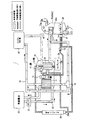
図1は、本発明の実施の形態の車両用空調装置を示す構成図である。 FIG. 1 is a configuration diagram illustrating a vehicle air conditioner according to an embodiment of the present invention.
本発明の実施形態の車両用空調装置1は、発熱部品としてのエンジン(内燃機関)を有する車両に搭載されて、車室内の空気調整を行う装置である。 A vehicle air conditioner 1 according to an embodiment of the present invention is mounted on a vehicle having an engine (internal combustion engine) as a heat generating component, and is a device that performs air conditioning in a vehicle interior.
実施形態の車両用空調装置1は、構成ユニット10、コンプレッサ(圧縮機)38、エンジン冷却部40、ヒーターコア44、エバポレータ48、膨張弁37、室外コンデンサ39、逆止弁15、三方弁18(第1切換手段に相当)、車載電池20、ポンプ21、および、これらの間を結ぶ冷却液の配管および冷媒配管等を具備する。ヒーターコア44と、エバポレータ48とは、HVAC(Heating, Ventilation, and Air Conditioning)70の吸気通路内に配置される。HVAC70には、吸気を流すファンF1が設けられている。
The vehicle air conditioner 1 according to the embodiment includes a
コンプレッサ38は、エンジンの動力または電気により駆動して、吸入した冷媒を高温高圧に圧縮して吐出する。圧縮された冷媒は、構成ユニット10へ送られる。低圧の冷媒は、構成ユニット10の第1水冷媒熱交換器11、又は、エバポレータ48から、合流管を介してコンプレッサ38へ吸入される。
The
エンジン冷却部40は、エンジンの周囲に冷却液を流すウォータジャケットと、ウォータジャケットに冷却液を流すポンプとを具備し、ウォータジャケットに流れる冷却液へエンジンから熱を放出させる。ポンプは、例えば、エンジンの動力により回転する。エンジン冷却部40には、エンジンの排熱の量が多くなった場合に、熱を外気に放出するラジエータが備わっていてもよい。エンジン冷却部40の冷却液の通路(エンジン冷却液通路19)は、構成ユニット10を通ってヒーターコア44と連通されている。
The
エンジン冷却液は、例えばLLC(Long Life Coolant)などの不凍液であり、熱を輸送するための液体である。 The engine coolant is an antifreeze such as LLC (Long Life Coolant), and is a liquid for transporting heat.
エンジン冷却液を移送する構成は、エンジン冷却部40のポンプのみとすることもできる。これにより、装置のコストの低減および装置の設置スペースの縮小を図ることができる。エンジン冷却液の移送能力を高めるために、冷却液配管の他の箇所にポンプを追加してもよい。
The configuration for transferring the engine coolant may be only the pump of the
ヒーターコア44は、エンジン冷却液と空気との間で熱交換を行う機器であり、車室内へ空気を供給するHVAC70の吸気通路内に配置される。ヒーターコア44には、加熱されたエンジン冷却液が供給され、暖房運転時に車室内へ送られる吸気(車室内への送風)に熱を放出する。ヒーターコア44は、ドア44aの開度により通過する空気の量を調整可能になっている。ドア44aは、電気的な制御で開閉可能である。ドア44aは、ミックスドアとも呼ばれる。
The
エバポレータ48は、低温低圧の冷媒と、空気との間で熱交換を行う機器であり、HVAC70の吸気通路内に配置される。エバポレータ48には、冷房運転時または除湿運転時に低温低圧の冷媒が流され、車室内へ供給される吸気(車室内への送風)を冷却する。
The
膨張弁37は、高圧の冷媒を低温低圧に膨張して、エバポレータ48に吐出する。膨張弁37は、エバポレータ48に近接して配置されている。膨張弁37は、エバポレータ48から送出される冷媒の温度により吐出する冷媒量を自動的に調整する機能を有してもよい。
The
室外コンデンサ39は、冷媒を流す通路と、空気を流す通路とを有し、例えばエンジンルーム内の車両の先頭付近に配置されて、冷媒と外気との間で熱交換を行う。室外コンデンサ39には、冷房モードおよび除湿モードのときに、高温高圧の冷媒が流されて、冷媒から外気へ熱を排出させる。室外コンデンサ39には、例えば、ファンにより外気が吹き付けられる。室外コンデンサ39の冷媒の送出側にはリザーバタンク39aを設けてもよい。
The
室外コンデンサ39を通過した冷媒は、膨張弁37を介してエバポレータ48へ導入されると共に、分岐され構成ユニット10へも導入される。
The refrigerant that has passed through the
エンジン冷却部40から導出されたエンジン冷却液は、エンジン冷却液通路19を通過し構成ユニット10へ導入される。構成ユニット10を経由したエンジン冷却液は、ヒーターコア44を経由して、三方弁18へ導入される。
The engine coolant derived from the
三方弁18は、ヒーターコア44から導出されたエンジン冷却液通路19を流れるエンジン冷却液を、後述する構成ユニット10が備える第1水冷媒熱交換器11に流す状態と、第1水冷媒熱交換器11をバイパスする状態とを切り替える。
The three-
車載電池20は、例えば、電気自動車、ハイブリッド車における走行用モータの駆動現となる電気エネルギーを蓄積する二次電池である。車載電池20は、冷却など温度調節を要する部品である。車載電池20の温度調節には、LLCなどの不凍液である冷却液が用いられる。この冷却液は、部品温調通路22を通過し、構成ユニット10へ導入される。構成ユニット10にて冷却された冷却液は、部品温調通路22を通過して再び車載電池20へ導入される。部品温調通路22の冷却液の循環にはポンプ21が用いられる。部品温調通路22と、エンジン冷却液通路19とは、それぞれ独立した通路である。
The in-
構成ユニット10は、単体で工場生産される一体化された構成であり、車両の組み立て工程において、車両用空調装置1の他の構成と配管接続される。構成ユニット10は、1個の筐体に各構成要素が収容されて一体化されていてもよいし、各構成要素が接合されることで一体化されていてもよい。
The
構成ユニット10には、第1水冷媒熱交換器11と、第2水冷媒熱交換器12と、開閉弁(第2切換手段に相当)13と、膨張弁14と、開閉弁16(第2切換手段に相当)と、開閉弁17(第2切換手段に相当)とが含まれる。
The
第1水冷媒熱交換器11(蒸発器)は、低温低圧の冷媒を流す通路と、複数の冷却液を流す通路とを有し、冷媒と冷却液との間で熱交換を行う。第1水冷媒熱交換器11には、所定の運転モードのときに、膨張弁14から低温低圧の冷媒が吐出されて、冷却液から低温低圧冷媒へ熱を移動させる。これにより、第1水冷媒熱交換器11は低温低圧の冷媒を気化させる。
The first water refrigerant heat exchanger 11 (evaporator) has a passage through which a low-temperature and low-pressure refrigerant flows and a passage through which a plurality of cooling liquids flow, and performs heat exchange between the refrigerant and the cooling liquid. In the predetermined operation mode, the first water
第1水冷媒熱交換器11の冷却液の導入口の1つは、三方弁18を介してヒーターコア44に連通され、冷却液の送出口の1つは、エンジン冷却液通路19を介してエンジン冷却部40の導入口に連通されている。
One of the coolant inlets of the first water-
第1水冷媒熱交換器11の冷却液の導入口の1つは、部品温調通路22を介して車載電池20の冷却液の導出口に連通される。第1水冷媒熱交換器11の冷却液の送出口の1つは、部品温調通路22を介して車載電池20の冷却液の導入口に連通されている。
One of the coolant inlets of the first water-
第1水冷媒熱交換器11の冷媒の導入口は、配管を介して膨張弁14に連通され、冷媒の送出口は、コンプレッサ38の吸入口へ合流する配管に連通されている。
The refrigerant inlet of the first water-
第2水冷媒熱交換器12(凝縮器)は、高温高圧の冷媒を流す通路と、冷却液を流す通路とを有し、冷媒と冷却液との間で熱交換を行う。第2水冷媒熱交換器12には、エンジン冷却水の温度が低い運転モードのときに、コンプレッサ38から高温高圧の冷媒が送られて、高温高圧冷媒から冷却液へ熱を放出させる。冷却水の温度が低いとき、第2水冷媒熱交換器12は、高温高圧の冷媒を凝縮させる。
The second water refrigerant heat exchanger 12 (condenser) has a passage through which a high-temperature and high-pressure refrigerant flows and a passage through which a cooling liquid flows, and performs heat exchange between the refrigerant and the cooling liquid. In the operation mode in which the temperature of the engine coolant is low, the second water
第2水冷媒熱交換器12の冷却液の導入口は、エンジン冷却液通路19を介してエンジン冷却部40の導出口に連通される。第2水冷媒熱交換器12の冷却液の送出口は、エンジン冷却液通路19を介してヒーターコア44の導入口に連通されている。第2水冷媒熱交換器12の冷媒の導入口は、配管を介してコンプレッサ38の吐出口へ連通される。第2水冷媒熱交換器12の冷媒の送出口は、分岐配管を介して開閉弁17と膨張弁14とに連通されるとともに、分岐配管および開閉弁13を介して室外コンデンサ39に連通される。
The coolant inlet of the second water
また、室外コンデンサ39を通過し構成ユニット10へ導入された冷媒は、開閉弁16を介して膨張弁14に連通される。
Further, the refrigerant that has passed through the
開閉弁13、開閉弁16、および、開閉弁17は、例えば電気的な制御により、冷媒配管の開閉を切り替える弁である。開閉弁13、開閉弁16、および、開閉弁17は例えば電磁弁である。開閉弁13、開閉弁16、および、開閉弁17は第2切換手段に相当し、第2水冷媒熱交換器12から導出された冷媒を、エバポレータ48および第1水冷媒熱交換器11のうち、エバポレータ48のみに流す状態と、エバポレータ48および第1水冷媒熱交換器11の両者に流す状態とに切り替える。
The on-off
開閉弁13を開き、開閉弁16および開閉弁17を閉じるとエバポレータ48のみに流す状態となる。また、開閉弁17を閉じ、開閉弁13および開閉弁16を開くとエバポレータ48および第1水冷媒熱交換器11の両者に流す状態となる。
When the on-off
膨張弁14は、高圧の冷媒を低温低圧に膨張させる膨張弁として機能する弁である。
The
逆止弁15は、コンプレッサ38とエバポレータ48との間に設けられ、室外コンデンサ39およびエバポレータ48に冷媒が流されない運転モードのときに、冷媒の逆流を防ぐ弁である。ここで、開閉弁13および開閉弁16が閉じられ、かつ、開閉弁17が開かれ、第1水冷媒熱交換器11と第2水冷媒熱交換器12とを通る冷媒回路に冷媒が流される運転モードを考察する。この運転モードでは、開閉弁13が閉じられていることで、室外コンデンサ39とエバポレータ48とを通る冷媒回路は遮断される。しかしながら、この場合でも、外気が低いと、室外コンデンサ39およびエバポレータ48における冷媒圧力が低くなることがある。そして、この圧力低下があると、第1水冷媒熱交換器11および第2水冷媒熱交換器12の冷媒回路に流れている冷媒が、エバポレータ48側の冷媒回路へ逆流してしまう。この結果、第1水冷媒熱交換器11と第2水冷媒熱交換器12とを通る冷媒回路の冷媒量が最適な範囲から逸脱してしまい、このヒートポンプサイクルの効率が低下してしまう。しかしながら、逆止弁15があることで、このような不都合を回避することができる。
The
次に、車両用空調装置1の動作について説明する。 Next, the operation of the vehicle air conditioner 1 will be described.
車両用空調装置1では、温水式暖房モード、ヒートポンプ式暖房モード、温調モード、および、冷房モードなど、いくつかの動作モードに切り換えられて動作する。温水式暖房モードは、ヒートポンプを作動させずに車室内を暖房するモードである。ヒートポンプ式暖房モードは、ヒートポンプを作動させて車室内を暖房するモードである。冷房モードはヒートポンプの作用により車室内を冷房するモードである。また、低温冷媒による空気の冷却および除湿と高温の冷却液による空気の加熱とを適宜合わせて空気の温度および湿度の調整を行う温調モードも選択できる。以下では、冷房モードを代表例として説明する。 The vehicle air conditioner 1 operates by being switched to several operation modes such as a hot water heating mode, a heat pump heating mode, a temperature control mode, and a cooling mode. The hot water heating mode is a mode in which the passenger compartment is heated without operating the heat pump. The heat pump heating mode is a mode in which the vehicle interior is heated by operating the heat pump. The cooling mode is a mode in which the passenger compartment is cooled by the action of the heat pump. In addition, a temperature control mode in which air temperature and humidity are adjusted by appropriately combining air cooling and dehumidification with a low-temperature refrigerant and air heating with a high-temperature coolant can be selected. Hereinafter, the cooling mode will be described as a representative example.
[冷房モード]
図2は、冷房モードの動作を説明する図である。[Cooling mode]
FIG. 2 is a diagram for explaining the operation in the cooling mode.
冷房モードでは、図2に示すように、開閉弁13が開、開閉弁16が開、開閉弁17が閉に切り換えられる。また、ヒーターコア44のドア44aは、全閉される。
In the cooling mode, as shown in FIG. 2, the on-off
コンプレッサ38が作動することで、冷媒は、第2水冷媒熱交換器12、室外コンデンサ39、膨張弁37、エバポレータ48、および、コンプレッサ38を、この順で循環的に流れる。さらに、コンプレッサ38が吐出した冷媒は、第2水冷媒熱交換器12、室外コンデンサ39、開閉弁16、膨張弁14、第1水冷媒熱交換器11、および、コンプレッサ38を、この順で循環的に流れる。
When the
冷房モードでは、ヒーターコア44から導出されたエンジン冷却液通路19を流れるエンジン冷却液が第1水冷媒熱交換器11をバイパスする状態となるように、三方弁18(第1切換手段)を切り替える。
In the cooling mode, the three-way valve 18 (first switching means) is switched so that the engine coolant flowing through the
三方弁18をバイパスする状態とすることで、第1水冷媒熱交換器11には車載電池20から導出された冷却液のみが通過する。この冷却液は、第1水冷媒熱交換器11を通過することで冷却される。
By setting the three-
エンジン冷却液通路19を流れるエンジン冷却液はバイパスされ、冷却されないため、比較的に温度は高くなる。冷却液の放熱は、主に、エンジン冷却部40のラジエータで行われる。エンジンは非常に高温になるので、外気温が高くても、ラジエータによる放熱により適宜な冷却を行うことができる。ここで、冷却液を流す構成は、ラジエータ側に冷却液を多く流して、ヒーターコア44側の流れを低下させてもよい。
Since the engine coolant flowing through the
このように第2水冷媒熱交換器12の冷却液の温度は高くなるため、第2水冷媒熱交換器12おいて高温高圧冷媒の放熱量は大きくないが、高温高圧冷媒は続いて室外コンデンサ39へ送られて、空気に放熱を行うことで凝縮する。
Since the temperature of the coolant in the second water
凝縮された冷媒は、エバポレータ48側へ送られて、先ず、膨張弁37により膨張されて低温低圧冷媒となり、エバポレータ48にて車室内への送風を冷却する。この熱交換により冷媒は気化する。気化した低圧冷媒は、コンプレッサ38に吸引されて圧縮される。
The condensed refrigerant is sent to the
第2水冷媒熱交換器12、ヒーターコア44、および、第1水冷媒熱交換器11を流れる冷却液は、高温となるが、ヒーターコア44のドア44aの開度の調整により、車室内へ送られる吸気への放熱量は小さく調整される。
The coolant flowing through the second water
このような動作により、車室内の十分な冷房を行うことができる。 Such an operation can sufficiently cool the passenger compartment.
以上のように、本実施の形態の車両用空調装置1は、エンジン冷却液をヒーターコア44に流して暖房に利用する温水式ヒータの構成と、ヒートポンプの低温低圧冷媒を利用して冷房を行うヒートポンプ冷房装置の構成とを、基本構成としてあわせ持つ。そして、この基本構成に構成ユニット10が追加されて、ヒートポンプを利用した車室内の暖房が可能な構成となっている。このような構成により、エンジンが低温なときでも、ヒートポンプの作用により、少ないエネルギーで速やかに車室内の暖房を行うことが可能となる。
As described above, the vehicle air conditioner 1 according to the present embodiment performs cooling using the configuration of the hot water heater that uses the engine coolant to the
本実施の形態によれば、従来の車両で採用されているような温水式ヒータ、並びに、従来の車両で採用されているようなヒートポンプ式冷房装置の構成を基本としつつ、三方弁(第1切換手段)18によりエンジン冷却液をバイパス可能とすることで、温度調節を要する部品(車載電池20)を十分に冷却することができる。 According to the present embodiment, the three-way valve (the first one) is based on the configuration of the hot water heater as used in a conventional vehicle and the configuration of a heat pump type cooling device as used in a conventional vehicle. By allowing the engine coolant to be bypassed by the switching means 18, it is possible to sufficiently cool the component (vehicle battery 20) requiring temperature adjustment.
[ヒートポンプ式暖房モード]
次に、ヒートポンプ式暖房モードの動作を説明する。[Heat pump heating mode]
Next, the operation in the heat pump heating mode will be described.
ヒートポンプ式暖房モードでは、開閉弁13が閉、開閉弁16が閉、開閉弁17が開に切り換えられる。また、ヒーターコア44のドア44aは開かれる(例えば全開)。
In the heat pump heating mode, the on-off
開閉弁13(第2切換手段)は、第2水冷媒熱交換器12から送出された冷媒が、エバポレータ48側へ送られる状態と、エバポレータ48側へ送られない状態とに切り換え可能であり、開閉弁17(第2切換手段)は、第2水冷媒熱交換器12から送出された冷媒が、第1水冷媒熱交換器11へ送られる状態と、第1水冷媒熱交換器11へ送られない状態とに切り換え可能である。
The on-off valve 13 (second switching means) can be switched between a state where the refrigerant sent from the second water
コンプレッサ38が作動することで、コンプレッサ38の吐出冷媒は、第2水冷媒熱交換器12、膨張弁14、第1水冷媒熱交換器11、および、コンプレッサ38を、この順で循環的に流れる。
When the
このように、開閉弁13、開閉弁16、および、開閉弁17(第2切換手段)は、第2水冷媒熱交換器12、室外コンデンサ39、エバポレータ48、および、コンプレッサ38を含む循環経路に冷媒が流れ、且つ、第1水冷媒熱交換器11へ冷媒が流れない冷房モードの状態と、第2水冷媒熱交換器12、第1水冷媒熱交換器11、および、コンプレッサ38を含む循環経路に冷媒が流れるヒートポンプ式暖房モードの状態と、に少なくとも切り換え可能である。
As described above, the on-off
開閉弁13、開閉弁16、および、開閉弁17がヒートポンプ式暖房モードの状態に切り替えられた際、第1水冷媒熱交換器11にエンジン冷却液を流す状態(バイパスしない状態)に三方弁18(第1切換手段)を切り替えることが可能である。これにより、エンジン冷却液通路19を流れるエンジン冷却液、および、部品温調通路22を流れる冷却液の両者の冷却液から吸熱し暖房を実現することが可能となる。
When the on-off
[変形例]
図3は、本発明の実施の形態の車両用空調装置の変形例を示す構成図である。[Modification]
FIG. 3 is a configuration diagram showing a modification of the vehicle air conditioner according to the embodiment of the present invention.
この変形例は、図1の実施の形態に、冷媒経路の変更を加えたものである。図1と同様の構成は、同一符号を付して詳細な室外コンデンサ39説明を省略する。
In this modification, the refrigerant path is changed to the embodiment shown in FIG. The same components as those in FIG. 1 are denoted by the same reference numerals, and detailed description of the
図1においては、開閉弁13、開閉弁16、および、開閉弁17により、第2水冷媒熱交換器12から送出された冷媒を、エバポレータ48および第1水冷媒熱交換器11のうち、エバポレータ48のみに流す状態と、両者に流す状態とを切り替えを行った。これに対し、変形例の車両用空調装置1Aは、開閉弁23、開閉弁24、および、開閉弁25(第2切換手段)により、コンプレッサ38が吐出し第2水冷媒熱交換器12へ導入される冷媒を分岐させた冷媒を、エバポレータ48および第1水冷媒熱交換器11のうち、エバポレータ48のみに流す状態と、両者に流す状態とを切り替え可能としている。
In FIG. 1, the refrigerant sent from the second water-
具体的には、コンプレッサ38の吐出口は分岐配管を介して開閉弁23と、開閉弁24とに連通される。第2水冷媒熱交換器12の冷媒の導入口は、開閉弁24を介してコンプレッサ38の吐出口と連通する。第2水冷媒熱交換器12の冷媒の送出口は、膨張弁14を介して第1水冷媒熱交換器11の冷媒の導入口と連通する。第1水冷媒熱交換器11の冷媒の送出口は、コンプレッサ38の吸入口へ合流する配管に連通されている。開閉弁25は図1の開閉弁16と同様の役割をなす。
Specifically, the discharge port of the
また、コンプレッサ38の吐出口は分岐配管および開閉弁23をこの順で介して、室外コンデンサ39の冷媒の導入口と連通する。このように、第2水冷媒熱交換器12から第1水冷媒熱交換器11へ至る冷媒通路と、室外コンデンサ39からエバポレータ48へ至る冷媒通路とは異なる冷媒通路となっている。
The discharge port of the
図3に示すように、冷房モードでは、開閉弁23が開、開閉弁24が閉、開閉弁25が開に切り換えられる。また、ヒーターコア44のドア44aは、全閉される。
As shown in FIG. 3, in the cooling mode, the on-off valve 23 is opened, the on-off valve 24 is closed, and the on-off valve 25 is switched to open. Further, the
コンプレッサ38が作動することで、冷媒は、室外コンデンサ39、膨張弁37、エバポレータ48、および、コンプレッサ38を、この順で循環的に流れる。さらに、コンプレッサ38が吐出した冷媒は、室外コンデンサ39、開閉弁25、膨張弁14、第1水冷媒熱交換器11、および、コンプレッサ38を、この順で循環的に流れる。
When the
冷房モードでは、ヒーターコア44から導出されたエンジン冷却液通路19を流れるエンジン冷却液が第1水冷媒熱交換器11をバイパスする状態となるように、三方弁18(第1切換手段)を切り替える。
In the cooling mode, the three-way valve 18 (first switching means) is switched so that the engine coolant flowing through the
このように、図1と同様に、図3の変形例においても、ヒートポンプの冷媒をエバポレータ48および第1水冷媒熱交換器11の両者に流す状態に切り替えられた際、三方弁18を、エンジン冷却液が第1水冷媒熱交換器11をバイパスする状態に切り替えることが可能である。
As in FIG. 1, in the modified example of FIG. 3, when the refrigerant of the heat pump is switched to the state of flowing through both the
また、ヒートポンプ式暖房モードでは、開閉弁23が閉、開閉弁24が開、開閉弁25が閉に切り換えられる。また、ヒーターコア44のドア44aは開かれる(例えば全開)。
In the heat pump heating mode, the on-off valve 23 is closed, the on-off valve 24 is opened, and the on-off valve 25 is switched to closed. Further, the
コンプレッサ38が作動することで、コンプレッサ38の吐出冷媒は、第2水冷媒熱交換器12、膨張弁14、第1水冷媒熱交換器11、および、コンプレッサ38を、この順で循環的に流れる。
When the
開閉弁23、開閉弁24、および、開閉弁25(第2切換手段)がヒートポンプ式暖房モードの状態に切り替えられた際、第1水冷媒熱交換器11にエンジン冷却液を流す状態(バイパスしない状態)に三方弁18(第1切換手段)を切り替えることが可能である。これにより、エンジン冷却液通路19を流れるエンジン冷却液、および、部品温調通路22を流れる冷却液の両者の冷却液から吸熱し暖房を実現することが可能となる。
When the on-off valve 23, the on-off valve 24, and the on-off valve 25 (second switching means) are switched to the heat pump heating mode, the engine coolant is allowed to flow through the first water-refrigerant heat exchanger 11 (not bypassed). It is possible to switch the three-way valve 18 (first switching means) to a state. Thus, it is possible to realize heating by absorbing heat from both the engine coolant flowing through the
このように、開閉弁23、開閉弁24、および、開閉弁25(第2切換手段)により、
コンプレッサ38、第2水冷媒熱交換器12、および、第1水冷媒熱交換器11を含む冷媒回路に冷媒が流れる状態に切り換え可能である。このとき、第2水冷媒熱交換器12から第1水冷媒熱交換器11へ至る冷媒通路と、室外コンデンサ39からエバポレータ48へ至る冷媒通路とは異なる冷媒通路となっている。Thus, the on-off valve 23, on-off valve 24, and on-off valve 25 (second switching means)
The refrigerant can be switched to a state in which the refrigerant flows through the refrigerant circuit including the
以上のように、変形例の車両用空調装置1Aは、開閉弁23、開閉弁24、および、開閉弁25(第2切換手段)により、コンプレッサ38、第2水冷媒熱交換器12、および、第1水冷媒熱交換器11を含む冷媒回路に冷媒が流れる状態と、コンプレッサ38、室外コンデンサ39、および、エバポレータ48を含む冷媒回路に冷媒が流れる状態とに切換え可能である。また、変形例の車両用空調装置1Aは、第2水冷媒熱交換器12から第1水冷媒熱交換器11へ至る冷媒通路と、室外コンデンサ39からエバポレータ48へ至る冷媒通路とは異なる冷媒通路である。
As described above, the
また、開閉弁23、開閉弁24、および、開閉弁25は、ヒートポンプ式暖房モード時に、コンプレッサ38、第2水冷媒熱交換器12、および、第1水冷媒熱交換器11を含む冷媒回路に冷媒が流れる状態へ切り換え、冷房モード時に、コンプレッサ38、室外コンデンサ39、および、エバポレータ48を含む冷媒回路に冷媒が流れる状態へ切り換える。
Further, the on-off valve 23, the on-off valve 24, and the on-off valve 25 are provided in a refrigerant circuit including the
図3のような構成とすることで、以下の効果を奏する。第2水冷媒熱交換器12から第1水冷媒熱交換器11へ至る冷媒通路と、室外コンデンサ39からエバポレータ48へ至る冷媒通路とが異なるので、冷媒通路を、複数の動作モード(例えば冷房モードとヒートポンプ式暖房モード)に合うように、複数の動作モードで異ならせてチューニングすることができる。また、変形例の車両用空調装置1Aによれば、第1水冷媒熱交換器11の前で冷媒を膨張させる膨張弁14と、エバポレータ48の前で冷媒を膨張させる膨張弁37とを有しているので、膨張弁を、複数の動作モードに合うように、複数の動作モードで異ならせてチューニングすることができる。
With the configuration as shown in FIG. 3, the following effects are obtained. Since the refrigerant passage from the second water
本変形例では、冷房モードでは空気と冷媒とを熱交換させ、ヒートポンプ式暖房モードでは冷却液と冷媒とを熱交換させるが、複数の動作モードに合せてチューニングができることから、各動作モードに特化した動作性能を発揮させることが可能となる。また、動作モードをスムースに切り換えることが可能となる。また、第2水冷媒熱交換器12から第1水冷媒熱交換器11へ至る冷媒通路と、室外コンデンサ39からエバポレータ48へ至る冷媒通路との一部が共通だと、動作モードの切り替え時に、室外コンデンサ39に冷媒が貯まって回収困難となり、冷媒量が不安定になるという課題が考えられる。しかし、本変形例の車両用空調装置1Aでは、このような課題が生じ難い。
In this modification, heat is exchanged between the air and the refrigerant in the cooling mode, and heat is exchanged between the coolant and the refrigerant in the heat pump heating mode. However, tuning can be performed according to a plurality of operation modes. This makes it possible to exhibit improved operating performance. In addition, the operation mode can be switched smoothly. In addition, when a part of the refrigerant passage from the second water
以上、本発明の各実施の形態について説明した。 The embodiments of the present invention have been described above.
また、上記実施の形態では、第1切換手段として、三方弁18を採用した構成を例にとって説明した。しかしながら、三方弁18の機能を冷媒配管の分岐部に配置された複数の開閉弁で実現することも可能である。
Moreover, in the said embodiment, it demonstrated taking the case of the structure which employ | adopted the three-
上記実施の形態では、三方弁18を構成ユニット10の外に設けた構成を例にとって説明したが、三方弁18を構成ユニット10の中に設けてもよい。
In the above embodiment, the configuration in which the three-
また、上記実施の形態では、第2切換手段として、開閉弁13と、開閉弁16と、開閉弁17とを採用した構成を例にとって説明した。しかしながら、冷媒配管の分岐部に配置された三方弁で実現することも可能である。
Moreover, in the said embodiment, the structure which employ | adopted the on-off
また、上記実施の形態では、車両の温度調節を要する部品として車載電池を例にとって説明した。しかしながら、車両の温度調節を要する部品としては、電気自動車における走行用の電気モータなど、様々な温度調節を要する部品を採用してもよい。 Moreover, in the said embodiment, the vehicle-mounted battery was demonstrated as an example as components which require the temperature control of a vehicle. However, as a part that requires temperature adjustment of the vehicle, a part that requires various temperature adjustments such as an electric motor for traveling in an electric vehicle may be employed.
2013年7月26日出願の特願2013−155184の日本出願に含まれる明細書、図面および要約書の開示内容は、すべて本願に援用される。 The disclosure of the specification, drawings, and abstract included in the Japanese application of Japanese Patent Application No. 2013-155184 filed on July 26, 2013 is incorporated herein by reference.
本発明は、エンジン車、電気自動車、或いは、HEV車など温度調節を要する部品を搭載する各種車両に搭載される車両用空調装置に利用できる。 INDUSTRIAL APPLICABILITY The present invention can be used for a vehicle air conditioner mounted on various vehicles such as an engine vehicle, an electric vehicle, or an HEV vehicle on which components that require temperature adjustment are mounted.
1、1A 車両用空調装置
10 構成ユニット
11 第1水冷媒熱交換器
12 第2水冷媒熱交換器
13 開閉弁(第2切換手段)
14 膨張弁(第1膨張手段)
15 逆止弁
16 開閉弁(第2切換手段)
17 開閉弁(第2切換手段)
18 三方弁(第1切換手段)
19 エンジン冷却液通路
20 車載電池
21 ポンプ
22 部品温調通路
23 開閉弁(第2切換手段)
24 開閉弁(第2切換手段)
25 開閉弁(第2切換手段)
37 膨張弁(第2膨張手段)
38 コンプレッサ
39 室外コンデンサ(コンデンサ)
40 エンジン冷却部
44 ヒーターコア
44a ドア
48 エバポレータ
70 HVAC
DESCRIPTION OF
14 Expansion valve (first expansion means)
15
17 On-off valve (second switching means)
18 Three-way valve (first switching means)
19
24 On-off valve (second switching means)
25 On-off valve (second switching means)
37 Expansion valve (second expansion means)
38
40
Claims (15)
エンジンを冷却するエンジン冷却部から導出されたエンジン冷却液を流すエンジン冷却液通路と、
前記エンジン冷却液通路を流れる前記エンジン冷却液が流されて車室内へ送られる空気を加熱可能なヒーターコアと、
ヒートポンプの低温低圧の冷媒と、前記部品温調通路を流れる冷却液との間、および、前記ヒートポンプの低温低圧の前記冷媒と、前記エンジン冷却液通路を流れる前記エンジン冷却液との間で互いに熱交換させる第1水冷媒熱交換器と、
前記ヒートポンプの高温高圧の冷媒と前記エンジン冷却液通路を流れる前記エンジン冷却液とを互いに熱交換させる第2水冷媒熱交換器と、
を備え、
前記エンジン冷却液通路は、前記エンジン冷却部から導出されたエンジン冷却液が、前記第2水冷媒熱交換器、前記ヒーターコア、および、前記第1水冷媒熱交換器をこの順に経由して、前記エンジン冷却部に戻るように構成されており、
前記エンジン冷却液通路を流れる前記エンジン冷却液を、前記第1水冷媒熱交換器に流す状態と、前記第1水冷媒熱交換器をバイパスする状態とを切り替え可能な第1切換手段と、
をさらに具備する、
車両用空調装置。 A temperature control passage for a coolant that allows heat to be exchanged with a component that requires temperature adjustment in the vehicle;
An engine coolant passage for flowing engine coolant derived from an engine cooling section for cooling the engine;
A heater core capable of heating air sent through the engine coolant flowing through the engine coolant passage to the vehicle interior;
Heat is generated between the low-temperature and low-pressure refrigerant of the heat pump and the coolant flowing through the component temperature control passage, and between the low-temperature and low-pressure refrigerant of the heat pump and the engine coolant flowing through the engine coolant passage. A first water refrigerant heat exchanger to be exchanged;
A second water refrigerant heat exchanger for exchanging heat between the high-temperature and high-pressure refrigerant of the heat pump and the engine coolant flowing through the engine coolant passage;
With
In the engine coolant passage, the engine coolant derived from the engine cooling section passes through the second water refrigerant heat exchanger, the heater core, and the first water refrigerant heat exchanger in this order, Configured to return to the engine cooling section,
A first switching means capable of switching between a state in which the engine coolant flowing through the engine coolant passage flows to the first water refrigerant heat exchanger and a state in which the first water refrigerant heat exchanger is bypassed;
Further comprising
Vehicle air conditioner.
請求項1記載の車両用空調装置。 The component temperature adjustment passage and the engine coolant passage are independent passages, respectively.
The vehicle air conditioner according to claim 1.
前記ヒートポンプの冷媒を、前記エバポレータおよび前記第1水冷媒熱交換器のうち、
前記エバポレータのみに流す状態と、両者に流す状態とを切り替え可能な第2切換手段とをさらに具備する、
請求項1または請求項2に記載の車両用空調装置。 Further comprising an evaporator capable of cooling the air sent to the passenger compartment by flowing the refrigerant of the heat pump;
The refrigerant of the heat pump, the evaporator and the first water refrigerant heat exchanger,
A second switching means capable of switching between a state of flowing only to the evaporator and a state of flowing to both;
The vehicle air conditioner according to claim 1 or 2.
前記第1切換手段を、前記エンジン冷却液が前記第1水冷媒熱交換器をバイパスする状態に切り替える、
請求項3に記載の車両用空調装置。 When the second switching means is switched to a state in which the refrigerant of the heat pump flows to both the evaporator and the first water refrigerant heat exchanger,
Switching the first switching means to a state in which the engine coolant bypasses the first water-refrigerant heat exchanger;
The vehicle air conditioner according to claim 3.
前記第2水冷媒熱交換器から送出された冷媒が、前記エバポレータ側へ送られる状態と、前記エバポレータ側へ送られない状態とに切り換え可能であり、かつ、前記第2水冷媒熱交換器から送出された冷媒が、前記第1水冷媒熱交換器へ送られる状態と、前記第1水冷媒熱交換器へ送られない状態とに切り換え可能である、
請求項3または請求項4に記載の車両用空調装置。 The second switching means includes
The refrigerant sent from the second water refrigerant heat exchanger can be switched between a state where it is sent to the evaporator side and a state where it is not sent to the evaporator side, and from the second water refrigerant heat exchanger The refrigerant sent out can be switched between a state where the refrigerant is sent to the first water refrigerant heat exchanger and a state where the refrigerant is not sent to the first water refrigerant heat exchanger.
The vehicle air conditioner according to claim 3 or 4.
前記第2水冷媒熱交換器、高温高圧の冷媒から外気へ放熱させ冷媒を凝縮させるコンデンサ、前記エバポレータ、および、冷媒を圧縮するコンプレッサを含む循環経路に冷媒が流れ、且つ、前記第1水冷媒熱交換器へ冷媒が流れない冷房モードの状態と、
前記第2水冷媒熱交換器、前記第1水冷媒熱交換器、および、前記コンプレッサを含む循環経路に冷媒が流れるヒートポンプ式暖房モードの状態と、
に少なくとも切り換え可能である、
請求項5記載の車両用空調装置。 The second switching means includes
The second water refrigerant heat exchanger, the condenser that radiates heat from the high-temperature and high-pressure refrigerant to the outside air, condenses the refrigerant, the evaporator, and a refrigerant that flows through a circulation path including the compressor that compresses the refrigerant, and the first water refrigerant A cooling mode state in which refrigerant does not flow to the heat exchanger;
A state of a heat pump heating mode in which the refrigerant flows through a circulation path including the second water refrigerant heat exchanger, the first water refrigerant heat exchanger, and the compressor;
At least switchable to
The vehicle air conditioner according to claim 5.
請求項6記載の車両用空調装置。 When the second switching means is switched to the state of the heat pump heating mode, the first switching means is switched to a state in which the engine coolant flows through the first water-refrigerant heat exchanger;
The vehicle air conditioner according to claim 6.
請求項6または請求項7に記載の車両用空調装置。 A check valve disposed in a passage for flowing a refrigerant from the evaporator to the compressor;
The vehicle air conditioner according to claim 6 or 7.
前記コンデンサにより凝縮されたれた冷媒を低温低圧に膨張して前記エバポレータへ吐出する第2膨張手段と、をさらに具備する、
請求項6〜請求項8の何れか一項に記載の車両用空調装置。 First expansion means for expanding the refrigerant sent from the second water refrigerant heat exchanger and sending the refrigerant to the first water refrigerant heat exchanger;
A second expansion means for expanding the refrigerant condensed by the condenser to a low temperature and low pressure and discharging the refrigerant to the evaporator;
The vehicle air conditioner according to any one of claims 6 to 8.
冷媒を圧縮するコンプレッサ、前記第2水冷媒熱交換器、および、前記第1水冷媒熱交換器を含む冷媒回路に冷媒が流れる状態と、前記コンプレッサ、高温高圧の冷媒から外気へ放熱させ冷媒を凝縮させるコンデンサ、および、前記エバポレータを含む冷媒回路に冷媒が流れる状態とに切換え可能であり、
前記第2水冷媒熱交換器から前記第1水冷媒熱交換器へ至る冷媒通路と、前記コンデンサから前記エバポレータへ至る冷媒通路とは異なる冷媒通路である、
請求項3または請求項4に記載の車両用空調装置。 The second switching means includes
A state in which the refrigerant flows through a refrigerant circuit including a compressor that compresses the refrigerant, the second water refrigerant heat exchanger, and the first water refrigerant heat exchanger; and the refrigerant that radiates heat from the high temperature and high pressure refrigerant to the outside air. A condenser to be condensed, and can be switched to a state in which a refrigerant flows through a refrigerant circuit including the evaporator,
A refrigerant passage from the second water refrigerant heat exchanger to the first water refrigerant heat exchanger and a refrigerant passage from the capacitor to the evaporator are different refrigerant passages,
The vehicle air conditioner according to claim 3 or 4.
ヒートポンプ式暖房モード時に、前記コンプレッサ、前記第2水冷媒熱交換器、および、前記第1水冷媒熱交換器を含む冷媒回路に冷媒が流れる状態へ切り換え、
冷房モード時に、前記コンプレッサ、前記コンデンサ、および、前記エバポレータを含
む冷媒回路に冷媒が流れる状態へ切り換える、
請求項10記載の車両用空調装置。 The second switching means includes
In the heat pump heating mode, switching to a state in which refrigerant flows through a refrigerant circuit including the compressor, the second water refrigerant heat exchanger, and the first water refrigerant heat exchanger,
In the cooling mode, switching to a state in which refrigerant flows through a refrigerant circuit including the compressor, the condenser, and the evaporator,
The vehicle air conditioner according to claim 10.
請求項11記載の車両用空調装置。 When the second switching means is switched to the state of the heat pump heating mode, the first switching means is switched to a state in which the engine coolant flows through the first water-refrigerant heat exchanger;
The vehicle air conditioner according to claim 11.
請求項11または請求項12に記載の車両用空調装置。 A check valve disposed in a passage for flowing a refrigerant from the evaporator to the compressor;
The vehicle air conditioner according to claim 11 or 12.
前記コンデンサにより凝縮されたれた冷媒を低温低圧に膨張して前記エバポレータへ吐出する第2膨張手段と、
をさらに具備する、
請求項11〜請求項13の何れか一項に記載の車両用空調装置。 First expansion means for expanding the refrigerant sent from the second water refrigerant heat exchanger and sending the refrigerant to the first water refrigerant heat exchanger;
Second expansion means for expanding the refrigerant condensed by the condenser to a low temperature and low pressure and discharging it to the evaporator;
Further comprising
The vehicle air conditioner according to any one of claims 11 to 13.
前記エンジン冷却液は、前記エンジン冷却部、前記第2水冷媒熱交換器、前記ヒーターコア、前記第1切換手段、および、前記第1水冷媒熱交換器をこの順に経由して、前記エンジン冷却部へ戻るように流れ、
前記第1切換手段が前記バイパスする状態であるとき、
前記エンジン冷却液は、前記エンジン冷却部、前記第2水冷媒熱交換器、前記ヒーターコア、および、前記第1切換手段をこの順に経由して、前記エンジン冷却部へ戻るように流れる、
請求項1〜請求項14の何れか一項に記載の車両用空調装置。 When the first switching means is in a state of flowing the engine coolant through the first water refrigerant heat exchanger,
The engine coolant passes through the engine cooling unit, the second water refrigerant heat exchanger, the heater core, the first switching means, and the first water refrigerant heat exchanger in this order, and then cools the engine cooling liquid. Flow back to the department,
When the first switching means is in the bypass state,
The engine coolant flows through the engine cooling unit, the second water refrigerant heat exchanger, the heater core, and the first switching unit in this order so as to return to the engine cooling unit.
The vehicle air conditioner according to any one of claims 1 to 14.
Applications Claiming Priority (3)
| Application Number | Priority Date | Filing Date | Title |
|---|---|---|---|
| JP2013155184 | 2013-07-26 | ||
| JP2013155184 | 2013-07-26 | ||
| PCT/JP2014/003866 WO2015011918A1 (en) | 2013-07-26 | 2014-07-23 | Vehicle air conditioner |
Publications (2)
| Publication Number | Publication Date |
|---|---|
| JPWO2015011918A1 JPWO2015011918A1 (en) | 2017-03-02 |
| JP6361029B2 true JP6361029B2 (en) | 2018-07-25 |
Family
ID=52392982
Family Applications (1)
| Application Number | Title | Priority Date | Filing Date |
|---|---|---|---|
| JP2015528147A Expired - Fee Related JP6361029B2 (en) | 2013-07-26 | 2014-07-23 | Air conditioner for vehicles |
Country Status (5)
| Country | Link |
|---|---|
| US (1) | US10071614B2 (en) |
| EP (1) | EP3025887B1 (en) |
| JP (1) | JP6361029B2 (en) |
| CN (1) | CN105431313B (en) |
| WO (1) | WO2015011918A1 (en) |
Families Citing this family (19)
| Publication number | Priority date | Publication date | Assignee | Title |
|---|---|---|---|---|
| JP6269307B2 (en) * | 2014-05-13 | 2018-01-31 | 株式会社デンソー | Air conditioner for vehicles |
| JP6605928B2 (en) * | 2014-11-27 | 2019-11-13 | マレリ株式会社 | Air conditioner for vehicles |
| CN106314065B (en) * | 2015-06-15 | 2018-10-16 | 比亚迪股份有限公司 | Automotive air-conditioning system and its control method, automobile |
| DE102015218824A1 (en) * | 2015-09-30 | 2017-03-30 | Bayerische Motoren Werke Aktiengesellschaft | Heat pump system and method of operating such |
| JP2017171247A (en) * | 2016-03-25 | 2017-09-28 | パナソニックIpマネジメント株式会社 | Vehicular air conditioning apparatus |
| JPWO2017217099A1 (en) * | 2016-06-16 | 2018-11-08 | 株式会社デンソー | Refrigeration cycle equipment |
| US10603978B2 (en) * | 2016-07-20 | 2020-03-31 | Ford Global Technologies, Llc | Vehicle auxiliary HVAC system using a coolant loop for cooling a component and vehicle interior |
| CN107472000A (en) * | 2016-08-08 | 2017-12-15 | 宝沃汽车(中国)有限公司 | The cooling system of vehicle |
| CN107487145B (en) * | 2016-09-19 | 2020-01-17 | 宝沃汽车(中国)有限公司 | Cooling system and vehicle with same |
| US10696134B2 (en) | 2017-02-16 | 2020-06-30 | Toyota Motor Engineering & Manufacturing North America, Inc. | Vehicle coolant flow control during maximum AC cooling condition |
| KR102445224B1 (en) * | 2017-10-27 | 2022-09-20 | 한온시스템 주식회사 | Heat pump system for vehicle and control method |
| JP6885308B2 (en) * | 2017-11-20 | 2021-06-09 | トヨタ自動車株式会社 | Vehicle temperature control system |
| JP6596774B2 (en) * | 2017-12-28 | 2019-10-30 | 本田技研工業株式会社 | Vehicle with electric motor |
| US10752087B2 (en) * | 2018-01-10 | 2020-08-25 | Denso International America, Inc. | Vehicle refrigeration system including cabin and outdoor condenser circuits with a holding reservoir and a bypass controlled outside subcool heat exchanger for heating output control of condensers |
| JP6919611B2 (en) * | 2018-03-26 | 2021-08-18 | トヨタ自動車株式会社 | Vehicle temperature control device |
| CN110315931A (en) * | 2018-03-30 | 2019-10-11 | 郑州宇通客车股份有限公司 | A kind of hybrid vehicle and its heat management system |
| JP7147279B2 (en) * | 2018-06-08 | 2022-10-05 | 株式会社デンソー | Vehicle refrigeration cycle equipment |
| CN109291761B (en) * | 2018-11-09 | 2023-09-12 | 上海加冷松芝汽车空调股份有限公司 | Heat pump air conditioning system of electric automobile |
| US20220212518A1 (en) * | 2019-09-19 | 2022-07-07 | Hangzhou Sanhua Research Institute Co., Ltd. | Thermal management system |
Family Cites Families (19)
| Publication number | Priority date | Publication date | Assignee | Title |
|---|---|---|---|---|
| JPH06143974A (en) * | 1992-11-12 | 1994-05-24 | Zexel Corp | Air conditioner |
| US5641016A (en) * | 1993-12-27 | 1997-06-24 | Nippondenso Co., Ltd. | Air-conditioning apparatus for vehicle use |
| JPH1076837A (en) | 1996-09-06 | 1998-03-24 | Calsonic Corp | Heating system for automobile |
| JP2000108640A (en) | 1998-10-02 | 2000-04-18 | Zexel Corp | Air conditioner |
| US6332497B1 (en) * | 1999-06-07 | 2001-12-25 | Mitsubishi Heavy Industries, Ltd. | Vehicular air conditioner |
| DE10029934A1 (en) * | 2000-06-17 | 2002-01-03 | Behr Gmbh & Co | Air conditioning with air conditioning and heat pump mode |
| JP3910384B2 (en) | 2000-10-13 | 2007-04-25 | 本田技研工業株式会社 | Battery cooling device for vehicle |
| DE10128164A1 (en) * | 2001-06-09 | 2002-12-12 | Behr Gmbh & Co | Vehicle cooling system for a temperature-increasing device and method for cooling the temperature-increasing device |
| JP3993760B2 (en) * | 2001-11-02 | 2007-10-17 | 株式会社日本クライメイトシステムズ | Air conditioner for vehicles |
| JP2006321389A (en) | 2005-05-19 | 2006-11-30 | Denso Corp | Waste heat using device for vehicle |
| DE102007004979A1 (en) * | 2007-02-01 | 2008-08-07 | Daimler Ag | Traction battery cooling and/or tempering device for use in motor vehicle i.e. hybrid vehicle, has battery and cooling circuit thermally coupled with each other by refrigerant circuit to release heat on part of battery with low temperature |
| US7789176B2 (en) * | 2007-04-11 | 2010-09-07 | Tesla Motors, Inc. | Electric vehicle thermal management system |
| US8272432B2 (en) * | 2007-11-28 | 2012-09-25 | GM Global Technology Operations LLC | HVAC thermal storage for hybrid vehicle |
| WO2010079818A1 (en) | 2009-01-09 | 2010-07-15 | カルソニックカンセイ株式会社 | Air conditioning device for vehicle |
| JP2010159008A (en) | 2009-01-09 | 2010-07-22 | Calsonic Kansei Corp | Air conditioner for vehicle |
| JP2010260449A (en) * | 2009-05-07 | 2010-11-18 | Nippon Soken Inc | Air conditioner for vehicle |
| JP5437906B2 (en) * | 2010-05-14 | 2014-03-12 | 株式会社豊田中央研究所 | Battery heating device |
| JP5370402B2 (en) * | 2011-03-28 | 2013-12-18 | 株式会社デンソー | Air conditioner for vehicles |
| JP5861495B2 (en) * | 2011-04-18 | 2016-02-16 | 株式会社デンソー | VEHICLE TEMPERATURE CONTROL DEVICE AND IN-VEHICLE HEAT SYSTEM |
-
2014
- 2014-07-23 CN CN201480042215.8A patent/CN105431313B/en not_active Expired - Fee Related
- 2014-07-23 US US14/903,569 patent/US10071614B2/en not_active Expired - Fee Related
- 2014-07-23 WO PCT/JP2014/003866 patent/WO2015011918A1/en active Application Filing
- 2014-07-23 EP EP14830350.6A patent/EP3025887B1/en not_active Not-in-force
- 2014-07-23 JP JP2015528147A patent/JP6361029B2/en not_active Expired - Fee Related
Also Published As
| Publication number | Publication date |
|---|---|
| CN105431313A (en) | 2016-03-23 |
| EP3025887B1 (en) | 2018-04-25 |
| JPWO2015011918A1 (en) | 2017-03-02 |
| CN105431313B (en) | 2017-12-05 |
| WO2015011918A1 (en) | 2015-01-29 |
| US20160159203A1 (en) | 2016-06-09 |
| US10071614B2 (en) | 2018-09-11 |
| EP3025887A4 (en) | 2017-04-05 |
| EP3025887A1 (en) | 2016-06-01 |
Similar Documents
| Publication | Publication Date | Title |
|---|---|---|
| JP6361029B2 (en) | Air conditioner for vehicles | |
| CN108698469B (en) | Heat pump system for vehicle | |
| JP6108322B2 (en) | Air conditioner for vehicles | |
| JP6304578B2 (en) | Air conditioner for vehicles | |
| EP3025885B1 (en) | Vehicle air conditioner | |
| KR102024077B1 (en) | Battery heating device for vehicle | |
| WO2016059791A1 (en) | Air conditioning device for vehicle | |
| JP6590321B2 (en) | Air conditioner for vehicles | |
| WO2015098049A1 (en) | Air conditioning device for vehicle | |
| WO2016103578A1 (en) | Air conditioning device for vehicle | |
| WO2015008463A1 (en) | Vehicle air conditioner and constituent unit thereof | |
| JP6315222B2 (en) | Units for vehicle air conditioners | |
| WO2014136446A1 (en) | Air conditioning device for vehicles | |
| JP6241663B2 (en) | Air conditioner for vehicles | |
| WO2020059354A1 (en) | Vehicle air conditioner | |
| JP2018177096A (en) | Vehicle air conditioner | |
| KR20220009163A (en) | Automotive thermal management system | |
| KR20200063382A (en) | Air-conditioning system for electric vehicles |
Legal Events
| Date | Code | Title | Description |
|---|---|---|---|
| A521 | Request for written amendment filed |
Free format text: JAPANESE INTERMEDIATE CODE: A523 Effective date: 20170427 |
|
| A621 | Written request for application examination |
Free format text: JAPANESE INTERMEDIATE CODE: A621 Effective date: 20170427 |
|
| TRDD | Decision of grant or rejection written | ||
| A01 | Written decision to grant a patent or to grant a registration (utility model) |
Free format text: JAPANESE INTERMEDIATE CODE: A01 Effective date: 20180515 |
|
| A61 | First payment of annual fees (during grant procedure) |
Free format text: JAPANESE INTERMEDIATE CODE: A61 Effective date: 20180528 |
|
| R151 | Written notification of patent or utility model registration |
Ref document number: 6361029 Country of ref document: JP Free format text: JAPANESE INTERMEDIATE CODE: R151 |
|
| LAPS | Cancellation because of no payment of annual fees |