WO2018047875A1 - ギア機構及びギア機構を有するモータと電気器具 - Google Patents
ギア機構及びギア機構を有するモータと電気器具 Download PDFInfo
- Publication number
- WO2018047875A1 WO2018047875A1 PCT/JP2017/032161 JP2017032161W WO2018047875A1 WO 2018047875 A1 WO2018047875 A1 WO 2018047875A1 JP 2017032161 W JP2017032161 W JP 2017032161W WO 2018047875 A1 WO2018047875 A1 WO 2018047875A1
- Authority
- WO
- WIPO (PCT)
- Prior art keywords
- gear
- bearing
- gear mechanism
- gear shaft
- shaft
- Prior art date
- Legal status (The legal status is an assumption and is not a legal conclusion. Google has not performed a legal analysis and makes no representation as to the accuracy of the status listed.)
- Ceased
Links
Images



Classifications
-
- F—MECHANICAL ENGINEERING; LIGHTING; HEATING; WEAPONS; BLASTING
- F16—ENGINEERING ELEMENTS AND UNITS; GENERAL MEASURES FOR PRODUCING AND MAINTAINING EFFECTIVE FUNCTIONING OF MACHINES OR INSTALLATIONS; THERMAL INSULATION IN GENERAL
- F16H—GEARING
- F16H57/00—General details of gearing
- F16H57/0018—Shaft assemblies for gearings
- F16H57/0031—Shaft assemblies for gearings with gearing elements rotatable supported on the shaft
-
- F—MECHANICAL ENGINEERING; LIGHTING; HEATING; WEAPONS; BLASTING
- F16—ENGINEERING ELEMENTS AND UNITS; GENERAL MEASURES FOR PRODUCING AND MAINTAINING EFFECTIVE FUNCTIONING OF MACHINES OR INSTALLATIONS; THERMAL INSULATION IN GENERAL
- F16H—GEARING
- F16H55/00—Elements with teeth or friction surfaces for conveying motion; Worms, pulleys or sheaves for gearing mechanisms
- F16H55/02—Toothed members; Worms
- F16H55/06—Use of materials; Use of treatments of toothed members or worms to affect their intrinsic material properties
-
- F—MECHANICAL ENGINEERING; LIGHTING; HEATING; WEAPONS; BLASTING
- F16—ENGINEERING ELEMENTS AND UNITS; GENERAL MEASURES FOR PRODUCING AND MAINTAINING EFFECTIVE FUNCTIONING OF MACHINES OR INSTALLATIONS; THERMAL INSULATION IN GENERAL
- F16H—GEARING
- F16H57/00—General details of gearing
- F16H57/04—Features relating to lubrication or cooling or heating
-
- F—MECHANICAL ENGINEERING; LIGHTING; HEATING; WEAPONS; BLASTING
- F16—ENGINEERING ELEMENTS AND UNITS; GENERAL MEASURES FOR PRODUCING AND MAINTAINING EFFECTIVE FUNCTIONING OF MACHINES OR INSTALLATIONS; THERMAL INSULATION IN GENERAL
- F16H—GEARING
- F16H57/00—General details of gearing
- F16H57/04—Features relating to lubrication or cooling or heating
- F16H57/0467—Elements of gearings to be lubricated, cooled or heated
- F16H57/0469—Bearings or seals
- F16H57/0471—Bearing
-
- H—ELECTRICITY
- H02—GENERATION; CONVERSION OR DISTRIBUTION OF ELECTRIC POWER
- H02K—DYNAMO-ELECTRIC MACHINES
- H02K7/00—Arrangements for handling mechanical energy structurally associated with dynamo-electric machines, e.g. structural association with mechanical driving motors or auxiliary dynamo-electric machines
- H02K7/10—Structural association with clutches, brakes, gears, pulleys or mechanical starters
- H02K7/116—Structural association with clutches, brakes, gears, pulleys or mechanical starters with gears
-
- F—MECHANICAL ENGINEERING; LIGHTING; HEATING; WEAPONS; BLASTING
- F16—ENGINEERING ELEMENTS AND UNITS; GENERAL MEASURES FOR PRODUCING AND MAINTAINING EFFECTIVE FUNCTIONING OF MACHINES OR INSTALLATIONS; THERMAL INSULATION IN GENERAL
- F16H—GEARING
- F16H55/00—Elements with teeth or friction surfaces for conveying motion; Worms, pulleys or sheaves for gearing mechanisms
- F16H55/02—Toothed members; Worms
- F16H55/17—Toothed wheels
-
- H—ELECTRICITY
- H02—GENERATION; CONVERSION OR DISTRIBUTION OF ELECTRIC POWER
- H02K—DYNAMO-ELECTRIC MACHINES
- H02K7/00—Arrangements for handling mechanical energy structurally associated with dynamo-electric machines, e.g. structural association with mechanical driving motors or auxiliary dynamo-electric machines
- H02K7/10—Structural association with clutches, brakes, gears, pulleys or mechanical starters
- H02K7/116—Structural association with clutches, brakes, gears, pulleys or mechanical starters with gears
- H02K7/1163—Structural association with clutches, brakes, gears, pulleys or mechanical starters with gears where at least two gears have non-parallel axes without having orbital motion
- H02K7/1166—Structural association with clutches, brakes, gears, pulleys or mechanical starters with gears where at least two gears have non-parallel axes without having orbital motion comprising worm and worm-wheel
Definitions
- the present disclosure relates to a gear mechanism.
- the present invention relates to a gear mechanism, a motor having the gear mechanism, and an electric appliance having the gear mechanism.
- a gear mechanism is connected to a motor or various electric appliances.
- the gear mechanism includes a gear shaft that rotates the gear and a gear bearing that supports the gear.
- a lubricating fluid for example, grease
- the gear shaft and the gear bearing rotate relative to each other through the lubricating fluid.
- both the outer peripheral surface of the gear shaft and the inner peripheral surface of the gear bearing are usually circular. Therefore, after the gear bearing is attached to the gear shaft, the gap between the gear shaft and the gear bearing is very narrow, the lubricating fluid exists in the gap, and after the gear bearing is attached to the gear shaft, The end face toward the gear side of the bearing contacts the surface of the gear over the entire circumference. For this reason, the gap between the gear bearing and the gear is also very narrow.
- the lubricating fluid is pushed out to the end face of the gear bearing toward the gear side.
- the gear bearing is press-fitted until it comes into contact with the gear, most of the lubricating fluid pushed out to the end face of the gear bearing is pushed further outward in the radial direction of the bearing, and a position other than the outer peripheral face of the gear bearing. Extruded. Therefore, most of the lubricating fluid is not retained between the gear shaft and the gear bearing. As a result, it becomes difficult to perform lubrication between the gear shaft and the gear bearing.
- an object of the present invention is to provide a gear mechanism, a motor including the gear mechanism, and an electric appliance.
- the gear mechanism includes a gear shaft having a central axis extending in the vertical direction as a rotation center, a gear perpendicular to the gear shaft and extending radially outward, and the gear shaft.
- a gear bearing positioned on the outer peripheral surface and rotatably supporting the gear, wherein the gear is in contact with a lower end surface of the gear bearing, and the receiving recess is recessed downward from the contact surface. And having.
- the motor has the gear mechanism.
- an appliance comprises the gear mechanism.
- the gear has an accommodation recess that is recessed downward from the contact surface with the bearing.
- FIG. 1 is a schematic configuration diagram of a gear mechanism in the first embodiment.
- FIG. 2 is a cross-sectional view along the axial direction of the gear mechanism in the first embodiment.
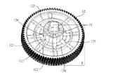
- FIG. 3 is a schematic diagram of one configuration of the gear and the gear shaft of the gear mechanism according to the first embodiment.
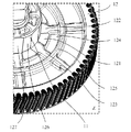
- FIG. 4 is a partially enlarged view of FIG. 5 is a cross-sectional view of the gear shaft and the gear bearing of the gear mechanism according to the first embodiment, taken along line XX in FIG.
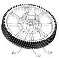
- FIG. 6 is a schematic diagram of another configuration of the gear and the gear shaft of the gear mechanism according to the first embodiment.
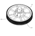
- FIG. 7 is a schematic diagram of another configuration of the gear and the gear shaft of the gear mechanism according to the first embodiment.
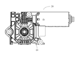
- FIG. 8 is a schematic configuration diagram of a motor in the second embodiment.
- a direction parallel to the direction extending to the gear shaft is referred to as “gear axis direction”.
- a radial direction around the gear shaft is referred to as a “radial direction”.
- a circumferential direction around the gear shaft is referred to as a “circumferential direction”.
- the direction along the gear shaft is referred to as “vertical direction”. Among them, in the vertical direction, the direction from the gear to the gear bearing is “upward”, and the direction opposite to “upward” is “downward”.
- the definitions of the upward direction and the downward direction are for convenience of description only, and there is no intention to limit the direction of use, installation, and manufacture of the motor.
- FIG. 1 is a schematic configuration diagram of the gear mechanism 10.
- FIG. 2 is a cross-sectional view along the axial direction of the gear mechanism of the first embodiment.
- FIG. 3 shows a state where no gear bearing is attached, and is a schematic diagram of one configuration of the gear and the gear shaft of the gear mechanism 10.
- FIG. 4 is a schematic diagram showing the configuration in the dotted frame Z in FIG. 3 in an enlarged manner.
- the gear mechanism 10 includes a gear shaft 11 having a center axis OO extending in the up-down direction as a rotation center, and is perpendicular to the gear shaft 11 and extends outward in the radial direction.
- the gear 12 and the gear bearing 13 which is located in the outer peripheral surface of the gear shaft 11, and supports the gear 12 rotatably are included.
- the gear shaft is a substantially cylindrical portion.
- a rotation shaft is passed through the gear shaft 11.
- the outer peripheral surface at the tip on the one axial side of the rotating shaft has a pair of circumferential surfaces opposed in the radial direction and a pair of flat portions opposed in the radial direction.
- the tip of one side of the rotating shaft in the axial direction protrudes above the end surface of the gear bearing 13 on the one side in the axial direction.
- the outer periphery of the tip on one side in the axial direction of the rotating shaft is located radially inside the outer periphery of the portion of the rotating shaft to which the gear bearing 13 is attached. In other words, a step is formed between the tip on one axial side of the rotating shaft and the portion of the rotating shaft where the gear bearing 13 is attached.
- the gear bearing 13 is attached to the outer peripheral surface of the gear shaft 11 by press fitting, for example.
- the gear 12 is substantially circular when viewed from the axial direction.
- the gear 12 extends radially outward from a gear shaft 11 extending along the central axis OO.
- a wall portion extending in the axial direction is formed at the radially outer end of the gear 12.
- a plurality of teeth are formed on the outer peripheral surface of the wall portion.
- the gear 12 is formed integrally with the gear shaft 11.
- the gear 12 and the gear shaft 11 may be configured separately.
- the gear 12 includes a contact surface 121 that contacts the lower end surface of the gear bearing 13, and an accommodation recess 122 that is recessed downward from the contact surface 121.
- a lubricating fluid for example, grease
- the gear bearing 13 is attached to the surface of the gear 12 by press-fitting, at least a part of the lubricating fluid positioned between the gear shaft 11 and the gear bearing 13 is pushed out to the lower surface of the gear bearing 13, and the accommodation recess 122. Housed inside. Therefore, it is suppressed that the lubricating fluid is pushed and spread to a portion other than the outer peripheral surface of the gear bearing 13.
- the lubricating fluid is not limited to grease, and may be any lubricant, and is not particularly limited.
- the lubricating fluid is preferably a semi-fluid, semi-solid or solid lubricant. In this embodiment, the lubricating fluid is preferably a non-Newtonian fluid rather than a Newtonian fluid.
- the number of contact surfaces 121 is not particularly limited and may be set arbitrarily. There may be one or more contact surfaces 121.
- the contact surface 121 may be a contact surface that is annularly arranged over the entire circumferential direction. In this case, an accommodation recess that extends in an annular shape and is disposed over the entire circumferential direction is provided on the inner circumference (that is, radially inward) of the annular contact surface 21.
- a plurality of annular housing recesses may be formed on the radially inner side of the annular contact surface 21.
- the accommodation recess 122 can include a spacing accommodation recess that is alternately arranged with the plurality of contact surfaces 121 in the circumferential direction.
- the contact surface 121 and the spacing accommodating recess are alternately arranged in the circumferential direction.
- the spacing bearing recess has a gear bearing.
- the lubricating fluid pushed out to the lower surface of 13 can be accommodated. Since the interval accommodating recesses are alternately arranged with the plurality of contact surfaces 121, the lubricating fluid can be dispersed and accommodated at a plurality of locations in the circumferential direction of the upper surface of the gear 12.
- the gear 12 rotates, the stored lubricating fluid easily flows between the contact surface 121 and the gear bearing 13, and the lubricating fluid is more evenly distributed between the contact surface 121 and the gear bearing 13. Can be spread. As a result, the gear shaft 11, the gear 12, and the gear bearing 13 can each rotate more smoothly. As a result, the gear mechanism 10 can be prevented from overheating.
- the plurality of contact surfaces 121 are connected to the gear shaft 11, and the plurality of alternately arranged interval receiving recesses are not connected to each other.
- the accommodation recess 122 is not limited to the above configuration, and may have another configuration having a spacing accommodation recess.
- the accommodation recess 122 may include a substantially annular recess having the gear shaft 11 as a center.
- the annular recess is recessed downward from the contact surface 121.
- the plurality of contact surfaces 121 are not connected to the gear shaft 11.
- Annular recesses are formed between the contact surfaces 121 and the gear shaft 11 in the radial direction, and the interval accommodating recesses communicate with each other via the annular recesses.
- an annular recess is disposed on the radially outer side of the outer peripheral surface of the gear shaft 11.
- a contact surface 121 and a spacing accommodating recess are disposed on the radially outer side of the annular recess.
- the contact surface 121 and the interval accommodating recess are alternately arranged in the circumferential direction.
- the interval accommodating recess communicates with the annular recess.
- the gear 12 includes an extended receiving groove 123 extending from the radially outer side of the receiving recess 122 toward the radially outer side, and provided on both sides in the circumferential direction of the extended receiving groove 123, and the contact surface. And an enlarged recess 124 that is recessed downward from 121.
- the extended accommodation grooves 123 extend substantially radially on the surface of the gear 12.
- the extended accommodation groove 123 communicates with the accommodation recess 122.
- the extension accommodating grooves 123 are arranged at equal intervals in the circumferential direction.
- the extension receiving groove 123 preferably extends to a cylindrical wall having the teeth of the gear 12.
- the enlarged recess 124 is located on the radially outer side of the contact surface 121.
- the circumferential width of the enlarged recess 124 is longer than the circumferential width of the contact surface 121.
- the circumferential width of the housing recess 122 is longer than the circumferential width of the extended housing groove 123.
- the extended accommodating groove 123 and the enlarged recessed portion 124 expand the passage of the lubricating fluid. That is, the accommodation recess 122, the extension accommodation groove 123, and the enlarged recess 124 constitute an accommodation space in which the lubricating fluid is accommodated.
- a larger amount of lubricating fluid can be held in the housing recess 122, the extension housing groove 123, and the enlarged recess 124, and the lubricating fluid can easily flow between the gear bearing 13 and the gear shaft 11, and the gear mechanism 10 can be moved.
- the gear shaft 11, the gear bearing 13, and the gear 12 which comprise can rotate more smoothly by lubrication with a lubricating fluid.
- the gear 12 may include a stop portion 125 that surrounds the radially outer side of the enlarged recess 124 and the extended accommodation groove 123 and protrudes upward.
- the stop portion 125 is substantially annular.
- the stopper part 125 is located on the radially outer side of the enlarged recess.
- the stopper 125 constitutes a part of the inner wall constituting the enlarged recess 124.
- An extension receiving groove 123 is connected to the stopper portion 125. More specifically, the extension accommodating groove 123 extends from the extension accommodating groove 123 accommodating recess 122 to the stopper portion 125.
- the lubricating fluid can be held inside the stopper portion 125, and the lubricating fluid can be prevented from entering a position other than the radially inner side of the stopper portion 125.
- the rigidity of the gear 12 can be improved because the gear 12 has the stopper portion 125.
- the extended accommodating groove 123 may extend further outward in the radial direction from the stopper portion 125.
- the gear shaft 11 may have a contact portion 126 that contacts the gear bearing 13 and a non-contact portion 127 that does not contact the gear bearing 13.
- the outer peripheral surface of the gear shaft 11 may have a contact portion 126 that contacts the gear bearing 13 and a non-contact portion 127 that does not contact the gear bearing 13.
- the contact portions 126 and the non-contact portions 127 are preferably arranged alternately in the circumferential direction.
- FIG. 5 is a cross-sectional view of the gear shaft 11 and the gear bearing 13 taken along the line XX in FIG.
- the inner surface 131 of the gear bearing 13 is substantially circumferential.
- the non-contact portion 127 is a plane extending in the axial direction. When viewed from the axial direction, the non-contact portion 127 is substantially linear.
- the contact portion 126 of the gear shaft 11 contacts the inner surface 131 of the gear bearing 13.
- a gap is formed between the non-contact portion 127 of the gear shaft 11 and the inner surface 131 of the gear bearing 13.
- the non-contact portion 127 of the gear shaft 11 faces the inner surface 131 of the gear bearing 13 with a gap therebetween.
- the non-contact portion 127 may have any configuration that is recessed radially inward from the contact portion 126.
- the non-contact portion 127 shown in FIG. 1 to FIG. 5 is a flat surface that extends to the gear 12 along the vertical direction and is formed on the outer peripheral surface of the gear shaft 11, but is not limited to this configuration. Absent.
- FIG. 6 shows another configuration of the non-contact portion 127. As shown in FIG. 6, the non-contact portion 127 may be a groove that extends to the gear 12 along the vertical direction and is recessed radially inward from the contact portion 126.
- the positional relationship of the housing recess 122 with respect to the contact part 126 and the non-contact part 127 can be arbitrarily set according to the configuration of the device.
- the accommodation recess 122 is connected to the non-contact portion 127.
- the configuration of the accommodation recess 122 is not limited to this.
- the accommodation recess 122 may be connected to the contact portion 126.
- the non-contact portion 127 and the accommodation recess 122 can constitute a passage that can contain the lubricating fluid.
- the lubricating fluid When the lubricating fluid is stored in the storage recess 122, when the gear shaft 11 is driven to rotate the gear 12, the lubricating fluid can flow into the gap between the gear shaft 11 and the gear bearing 13, and the gear shaft 11 And the gear bearing 13 can ensure a lubricating effect.
- the housing recess 122 By connecting the housing recess 122 to the non-contact portion 127, the passage of the lubricating fluid can be easily configured, and a higher lubrication effect can be obtained in the gear mechanism 10.
- the accommodation recess 122 may be connected to the gear shaft 11. Therefore, when the gear shaft 11 is driven and the gear 12 rotates, the lubricating fluid can easily flow between the gear shaft 11 and the gear bearing 13 from the housing recess 122.
- the housing recess 122 is not necessarily connected to the gear shaft 11.
- the housing recess 122 and the gear shaft 11 may be partitioned by the contact portion 121.
- the material of the gear shaft 11 and the material of the gear bearing 13 may be arbitrary materials.
- the gear shaft 11 may be made of a resin material.
- the gear bearing 13 may be made of a metal material. Thereby, the manufacturing cost of the gear mechanism 10 can be reduced. Further, when the gear shaft 11 is driven to rotate the gear 12, heat is generated in the gear shaft 11 and the gear 12 due to friction. As described above, the gear shaft 11 is located radially inward of the gear bearing 13. In other words, the gear bearing 13 is located radially outside the gear shaft 11.
- the resin material (gear shaft 11) located on the radially inner side has a higher thermal expansion coefficient than the metal material (gear bearing 13) located on the radially outer side.
- the gear mechanism 10 is provided with the housing recess 122 for housing the lubricating fluid, so that the lubrication effect in the gear mechanism 10 can be greatly improved.
- the gear mechanism 10 the lubricating fluid pushed out to the lower surface of the gear bearing 13 can be stored in the storage recess. Therefore, even when the gear bearing 13 is pressed into the surface of the gear 12, the lubricating fluid is not pushed out to a position other than the outer peripheral surface of the gear bearing 13. As a result, when the gear shaft 11 is driven and the gear 12 rotates, the stored lubricating fluid can easily flow between the gear shaft 11 and the gear bearing 13. Therefore, the lubrication effect of the gear mechanism 10 can be enhanced, and the friction between the gear shaft 11 and the gear bearing 12 can be reduced. As a result, the gear mechanism 10 can be prevented from overheating.
- FIG. 8 is a schematic configuration diagram of the motor 20. As shown in FIG. 8, the motor 20 has a gear mechanism 10. Since the gear mechanism 10 of the motor 20 is the same as that described above, description thereof is omitted here.
- the motor 20 of the second embodiment has the gear mechanism 10 described above, the motor 20 can contain the lubricating fluid pushed out to the lower surface of the gear bearing. Therefore, even when the gear bearing is press-fitted onto the surface of the gear, the lubricating fluid is not pushed out to a position other than the outer peripheral surface of the gear bearing.
- the gear shaft is driven to rotate the gear, Fluid tends to flow between the gear shaft and the gear bearing. Therefore, the lubrication effect can be guaranteed, the friction can be reduced, and the gear mechanism 10 can be prevented from overheating. And the heat of the gear mechanism 10 is transmitted to the motor 20, and it is suppressed that the motor 20 overheats.
- an electric appliance is imprinted.
- the appliance has a gear mechanism 10. Since the gear mechanism 10 included in the electric appliance is the same as that in the above-described embodiment, the description thereof is omitted here.
- the appliance may be any appliance that uses a gear mechanism.
- the electric appliance may be a sunroof mechanism attached to the vehicle body, for example.
- the gear mechanism 10 may be used as a gear mechanism for other electric appliances.
- the gear mechanism described above may be used as a gear mechanism for home appliances such as an indoor unit of an air conditioner, an outdoor unit of an air conditioner, a water dispenser, a washing machine, a vacuum cleaner, a compressor, a blower, and a blender, or various types of gear mechanisms. You may use as gear mechanisms, such as information equipment and an industrial machine.
- the present invention is not limited to the system of the above embodiment, and further includes all changes, modifications, and equivalents within the scope not exceeding the gist of the present invention.
Landscapes
- Engineering & Computer Science (AREA)
- General Engineering & Computer Science (AREA)
- Mechanical Engineering (AREA)
- Power Engineering (AREA)
- Physics & Mathematics (AREA)
- Electromagnetism (AREA)
- Thermal Sciences (AREA)
- General Details Of Gearings (AREA)
- Gear Transmission (AREA)
- Mounting Of Bearings Or Others (AREA)
Abstract
ギア機構は、上下方向に延びる中心軸を回転中心とするギアシャフトと、前記ギアシャフトに垂直し、径方向外側に延びるギアと、前記ギアシャフトの外周面に位置し、前記ギアを回転可能に支持するギア軸受と、を備え、前記ギアは、前記ギア軸受の下端面に接触する接触面と、前記接触面より、下方側に凹む収容凹部と、を有する。これにより、軸受の下面に押し出される潤滑流体が収容でき、軸受がギアに表面に圧入される時に潤滑流体は軸受の外周面以外に押し出されることが回避できる。
Description
本開示は、ギア機構に関わる。特に、ギア機構及び当該ギア機構を有するモータ、当該ギア機構を有する電気器具に関わる。
従来、モータや各種の電気器具などには、ギア機構が接続される。ギア機構は、ギアを回転させるギアシャフト及び当該ギアを支持するギア軸受を有する。ギアシャフトとギア軸受との摩擦によってギア機構が過熱することを防止するために、ギアシャフトとギア軸受との間に潤滑流体(例えば、グリースなど)を塗布することができる。当該潤滑流体を介して、ギアシャフトとギア軸受は相対回転する。
上記ギア構造を実現するためには、例えば、ギアシャフトの外周面に潤滑流体を塗布してから、ギア軸受をギアシャフトの延びる方向に沿ってギアに圧入する作業が必要となる。なお、上記背景技術はあくまでも本願発明の位置づけを明確に説明するためのものであり、当業者が理解しやすいために記載される。これらの技術が本願の背景技術部分で説明されたことを理由として、本願発明が当業者より知られたと認めてはならない。
ところが、従来のギア構造においては、ギアシャフトの延びる方向から見る際に、ギアシャフトの外周面及びギア軸受の内周面の何れも、通常、円周状である。従って、ギア軸受をギアシャフトに取り付けた後では、ギアシャフトとギア軸受との間の隙間は非常に狭く、潤滑流体はその隙間に存在し、且つ、ギア軸受をギアシャフトに取り付けた後に、ギア軸受のギア側に向かう端面は、円周全体においてギアの表面に接触する。そのため、ギア軸受とギアとの間の隙間も、非常に狭い。
従って、ギアシャフトと軸受との間の隙間が狭いので、潤滑流体が塗布されたギアシャフトにギア軸受を取り付ける工程においては、潤滑流体はギア軸受のギア側に向かう端面に押し出される。且つ、ギア軸受がギアに接触するまで圧入されるときに、ギア軸受の上記端面に押し出された潤滑流体の大部分は、更に軸受の径方向外側に押し出され、ギア軸受の外周面以外の位置に押し出される。そのため、大部分の潤滑流体はギアシャフトとギア軸受との間に保持されない。その結果、ギアシャフトとギア軸受との間における潤滑を行うことが困難になってしまう。
上記課題を解決するために、本発明は、ギア機構及び当該ギア機構を有するモータと電気器具を提供することを目的の一つとする。
本発明の例示的な第一発明によると、ギア機構は、上下方向に延びる中心軸を回転中心とするギアシャフトと、前記ギアシャフトに垂直し、径方向外側に延びるギアと、前記ギアシャフトの外周面に位置し、前記ギアを回転可能に支持するギア軸受と、を備え、前記ギアは、前記ギア軸受の下端面に接触する接触面と、前記接触面より、下方向側に凹む収容凹部と、を有する。
本発明の例示的な実施例の第二発明によると、モータは前記ギア機構を有する。
本発明の例示的な実施例の第三発明によると、電気器具は前記ギア機構を備える。
ギア機構において、ギアは、軸受との接触面より下方向側に凹む収容凹部を有する。これにより、軸受がギアの表面に圧入された場合に、軸受の端面に押し出される潤滑流体を収容凹部内に収容することができる。そのため、潤滑流体は軸受の外周面以外の位置に押し出されることはない。また、ギアが回転する際、収容された潤滑流体はギアシャフトとギア軸受との間に流入しやすい。従って、ギア機構に潤滑効果をもたらすことができる。その結果、ギアシャフトとギア軸受との間の摩擦を減少させることができ、ギア機構が過熱することが防止できる。
以下、図面を参考しながら、本発明の実施形態について詳述する。なお、本発明の実施形態の範囲は、本願の明細書および図面等に開示されている範囲に限定されるものではない。請求の範囲に記載された範囲内において、本発明の実施形態は変更、修正及び同等を含むものとする。
一つの実施形態に対して説明及び/又は示した特徴は、同じ又は類似する方法によって一つ又は複数の他の実施形態で使用されることができる。他の実施形態の特徴と組み合わせる、又は他の実施形態の特徴を代わることができる。
なお、本明細書で使用されるときに、「含む/含有/有する」等の表現は、特徴、部材全体、アセンブリが存在することを指すが、一つまたは複数の他の特徴、部材全体、アセンブリが存在する又は付加することを排除するわけではない。
本発明における前述ならびにその他の特徴、要素、手段、効果および特性については、図面を参照しつつ、以下の本発明の好ましい実施形態の詳細な説明によって、より明確にする。
本発明の下記説明において、便宜上、ギアシャフトに延びる方向に平行する方向を「ギア軸方向」と称する。ギアシャフトを中心とする半径方向を「径方向」と称する。ギアシャフトを中心とする円周方向を「周方向」と称する。尚、ギアシャフトに沿う方向を「上下方向」と称する。その中、当該上下方向において、ギアからギア軸受に指す方向は「上方向」である、「上方向」とは反対方向は「下方向」である。説明する必要があるのは、上記において上方向、下方向の定義はあくまでも説明便宜のためのものであり、モータの使用、取付及び製造時の向きを限定する意図はない。
以下、図面を参照して本発明の好ましい実施形態におけるギア機構、モータ及び電気器具を説明する。
<第1実施形態>
図1は、ギア機構10の構成模式図である。図2は、第1実施形態のギア機構の軸方向に沿う断面図である。ギア機構10の内部構成を明確に示すために、図3は、ギア軸受を取り付けていない状態を示しており、ギア機構10のギアとギアシャフトの一つの構成模式図である。図4は、図3の点線フレームZ内の構成を拡大して示す模式図である。
図1は、ギア機構10の構成模式図である。図2は、第1実施形態のギア機構の軸方向に沿う断面図である。ギア機構10の内部構成を明確に示すために、図3は、ギア軸受を取り付けていない状態を示しており、ギア機構10のギアとギアシャフトの一つの構成模式図である。図4は、図3の点線フレームZ内の構成を拡大して示す模式図である。
図1から図4に示すように、ギア機構10は、上下方向に延びる中心軸O-Oを回転中心とするギアシャフト11と、ギアシャフト11に対して垂直であり径方向外側に向かって延びるギア12と、ギアシャフト11の外周面に位置し、ギア12を回転可能に支持するギア軸受13と、を含む。ギアシャフトは、略筒状の部位である。ギアシャフト11には、回転シャフトが通される。回転シャフトの軸方向一方側の先端における外周面は、径方向に対向する一対の円周面と、径方向に対向する一対の平面部と、を有する。回転シャフトの軸方向一方側の先端部は、ギア軸受13の軸方向一方側の端面よりも、軸方向上側に突出する。回転シャフトの軸方向一方側の先端の外周は、回転シャフトにおけるギア軸受13が取り付けられている部分の外周よりも、径方向内側に位置する。言い換えると、回転シャフトの軸方向一方側の先端と回転シャフトにおけるギア軸受13が取り付けられている部分との間には、段差が形成される。ギア軸受13は、ギアシャフト11の外周面に対して、例えば、圧入により取り付けられる。軸方向から見たときに、ギア12は、略円形である。ギア12は、中心軸O-Oに沿って延びるギアシャフト11から径方向外側に拡がる。ギア12の径方向外側の端部には、軸方向に延びる壁部が形成される。壁部の外周面には、複数の歯が形成される。本実施形態では、ギア12は、ギアシャフト11と一体に形成されている。なお、ギア12とギアシャフト11とは、別体に構成されてもよい。
図3と図4に示すように、ギア12は、ギア軸受13の下端面に接触する接触面121と、接触面121より下方向に向かって凹む収容凹部122と、を含む。ギアシャフト11とギア軸受13との間には、潤滑流体(例えば、グリースなど)が塗布される。そのため、ギア軸受13がギア12の表面に圧入により取り付けられる際、ギアシャフト11とギア軸受13との間に位置する潤滑流体の少なくとも一部は、ギア軸受13の下面に押し出され、収容凹部122内に収容される。そのため、潤滑流体がギア軸受13の外周面以外の部位に押し出されて広がることが抑制される。ギアシャフト11が駆動してギア12が回転する際に、収容凹部122内に収容された潤滑流体はギアシャフト11とギア軸受13との間に流入することができる。従って、ギア機構10の各部材間において潤滑がなされ、ギアシャフト11とギア軸受13との間の摩擦を減少させることができ、ギアシャフト11、ギア軸受13、ギア12が、それぞれ、滑らかに回転することができる。その結果、ギア機構10が過熱することを抑制できる。なお、潤滑流体としては、グリースに限定されるものではなく、潤滑剤であればよく、特に限定されるものではない。潤滑流体は、好ましくは、半流動体、半固体状又は固体状の潤滑剤である。本実施形態では、潤滑流体は、ニュートン流体よりは、非ニュートン流体が望ましい。
本実施例において、接触面121の数は、特に限定されるものではなく、任意に設定すればよい。接触面121は、一つであってもよいし、複数であってもよい。例えば、接触面121は環状に周方向全体に亘って配置される接触する面であってもよい。この場合、環状の接触面21の内周(すなわち、径方向内側)には、環状に延び周方向全体に亘って配置される収容凹部が設けられる。なお、環状の接触面21の径方向内側に、環状の収容凹部が複数形成されてもよい。
接触面121が複数形成される場合、収容凹部122は、周方向において複数の接触面121と交互に配置される間隔収容凹部を含むことができる。言い換えると、接触面121と間隔収容凹部とが、周方向に交互に配置される、この場合でも、ギア軸受13がギアシャフト11に圧入により取り付けられる際に、間隔収容凹部内には、ギア軸受13の下面に押し出される潤滑流体を収容することができる。間隔収容凹部は複数の接触面121と交互に配置されるので、潤滑流体をギア12の上面の周方向における複数の箇所に分散して収容できる。そのため、ギア12が回転する際に、収容された潤滑流体は接触面121とギア軸受13との間に流入しやすくなり、接触面121とギア軸受13との間において、潤滑流体をより均一に広げることができる。その結果、ギアシャフト11、ギア12、およびギア軸受13が、それぞれ、より滑らかに回転することができる。その結果、ギア機構10が過熱することを抑制できる。図3に示される構成においては、複数の接触面121はギアシャフト11に接続され、複数の交互的に配置される間隔収容凹部同士は接続されていない。但し、収容凹部122は、上記構成に限られず、間隔収容凹部を有する他の構成であってもよい。例えば、収容凹部122は、ギアシャフト11を中心とする略環状の環状凹部を含んでもよい。当該環状凹部は、接触面121より下方向に凹む。この場合、複数の接触面121はギアシャフト11に接続されない。径方向において各接触面121とギアシャフト11との間に環状凹部が形成され、環状凹部を介して各間隔収容凹部が連通される。言い換えると、ギアシャフト11の外周面の径方向外側には、環状凹部が配置される。環状凹部の径方向外側には、接触面121および間隔収容凹部が配置される。接触面121および間隔収容凹部は周方向に交互に配置される。間隔収容凹部は環状凹部と連通する。
図3と図4に示すように、ギア12は、収容凹部122の径方向外側からさらに径方向外側に向かって延びる延長収容溝123と、延長収容溝123の周方向両側に設けられ且つ接触面121より下方向に向かって凹む拡大凹部124と、を更に含むことができる。中心軸O-O方向から見たときに、延長収容溝123は、ギア12の面上において略放射状に延びる。延長収容溝123は、収容凹部122と連通する。延長収容溝123は、周方向に等間隔に配置される。延長収容溝123は、好ましくは、ギア12の歯を有する円筒状の壁部まで延びる。拡大凹部124は、接触面121の径方向外側に位置する。拡大凹部124の周方向の幅は、接触面121の周方向の幅よりも、長い。収容凹部122の周方向の幅は、延長収容溝123の周方向の幅よりも、長い。延長収容溝123と拡大凹部124とによって、潤滑流体の通路が拡がる。すなわち、収容凹部122、延長収容溝123、および拡大凹部124によって、潤滑流体が収容される収容空間が構成される。そのため、より多量の潤滑流体を収容凹部122、延長収容溝123、および拡大凹部124に保持することができ、潤滑流体がギア軸受13及びギアシャフト11との間を流れやすくなり、ギア機構10を構成するギアシャフト11、ギア軸受13、およびギア12が、潤滑流体による潤滑によって、より滑らかに回転することができる。
さらに、ギア12は、拡大凹部124と延長収容溝123の径方向外側を囲み、上方向に向かって突出する当たり止め部125を含んでもよい。中心軸O-O方向から見たときに、当たり止め部125は、略環状である。当たり止め部125は、拡大凹部の径方向外側に位置する。当たり止め部125は、拡大凹部124を構成する内壁の一部を構成する。当たり止め部125には、延長収容溝123が接続される。より詳細には、延長収容溝123は、延長収容溝123収容凹部122から当たり止め部125まで延びる。この場合、潤滑流体を当たり止め部125の内部に保持させることができ、潤滑流体が当たり止め部125の径方向内側以外の位置に侵入することを防止できる。また、なお、ギア12が当たり止め部125を有することにより、ギア12の剛性を向上させることができる。延長収容溝123は、当たり止め部125からさらに径方向外側にまで延びてもよい。
図3および図4に示すように、ギアシャフト11は、ギア軸受13と接触する接触部126と、ギア軸受13と接触しない非接触部127とを有してもよい。言い換えると、ギアシャフト11の外周面は、ギア軸受13と接触する接触部126と、ギア軸受13と接触しない非接触部127と、を有してもよい。接触部126と非接触部127とは、周方向に交互に配置されるのが好ましい。
図5は、ギアシャフト11とギア軸受13の図2のX-Xに沿う断面図である。図5に示すように、ギア軸受13の内面131は、略円周状である。図3~図5に示すように、非接触部127は、軸方向に延びる平面である。軸方向から見たときに、非接触部127は略直線状である。ギア軸受13をギアシャフト11に取り付ける際に、ギアシャフト11の接触部126は、ギア軸受13の内面131に接触する。ギアシャフト11の非接触部127とギア軸受13の内面131との間には、隙間が形成される。言い換えれば、ギアシャフト11の非接触部127は、ギア軸受13の内面131と、間隙を介して対向する。
これにより、ギアシャフト11とギア軸受13とが圧入により取り付けられた際に、ギアシャフト11等に塗布された潤滑流体は、非接触部127とギア軸受13との間に形成された隙間に容易に流入でき、ギアシャフト11とギア軸受13との間に亘る。
なお、非接触部127は、接触部126より径方向内側に凹む任意の構成であってもよい。例えば、図1から図5に示された非接触部127は、上下方向に沿ってギア12までに延び、ギアシャフト11の外周面に形成される平面であるが、この構成に限られるものではない。図6は、非接触部127の他の構成を示している。図6に示すように、非接触部127は、上下方向に沿ってギア12までに延び、接触部126より径方向内側に凹む溝であってもよい。
収容凹部122の接触部126および非接触部127に対する位置関係は、機器の構成に応じて、任意に設定できる。例えば、図3と図4では、収容凹部122は非接触部127に接続される。しかしながら、収容凹部122の構成は、これに限られるものではない。例えば、図7に示すように、収容凹部122は、接触部126に接続されてもよい。非接触部127及び収容凹部122によって潤滑流体を収容可能な通路を構成することができる。収容凹部122内に潤滑流体が収容された場合、ギアシャフト11が駆動してギア12が回転する際に、潤滑流体はギアシャフト11とギア軸受13との間の隙間に流入でき、ギアシャフト11とギア軸受13との間における潤滑効果を確保できる。収容凹部122が非接触部127に接続されることにより、潤滑流体の通路を容易に構成することができ、ギア機構10においてより高い潤滑効果が得られる。
図3および図4に示すように、収容凹部122は、ギアシャフト11に接続されてもよい。従って、ギアシャフト11が駆動してギア12が回転する際、潤滑流体は収容凹部122からギアシャフト11とギア軸受13との間に容易に流入できる。しかしながら、収容凹部122は必ずしもギアシャフト11に接続されなくてもよい。例えば、接触部121によって収容凹部122とギアシャフト11とを仕切られてもよい。
ギアシャフト11の材料とギア軸受13の材料は、任意の材料であってよい。
例えば、ギアシャフト11は樹脂材料によって構成されてもよい。ギア軸受13は金属材料によって構成されてもよい。これにより、ギア機構10の製造コストを減少させることができる。また、ギアシャフト11が駆動してギア12が回転する際、摩擦によってギアシャフト11およびギア12には熱が発生する。上述のように、ギアシャフト11は、ギア軸受13よりも径方向内側に位置する。言い換えると、ギア軸受13はギアシャフト11よりも径方向外側に位置する。径方向内側に位置する樹脂材料(ギアシャフト11)は、径方向外側に位置する金属材料(ギア軸受13)よりも、高い熱膨張係数を有する。従って、摩擦によって発生した熱により、樹脂材料(ギアシャフト11)および金属材料(ギア軸受13)は熱によってそれぞれ膨張し、両者の熱膨張係数の違いからギアシャフト11とギア軸受13との間の隙間は更に小さくなる。そのため、従来のギア機構に比べると、本発明にかかるギア機構10は、潤滑流体を収容する収容凹部122が設けられていることによって、ギア機構10における潤滑効果を大幅に向上できる。
上述のように、ギア機構10では、ギア軸受13の下面に押し出された潤滑流体を収容凹部に収容できる。従って、ギア軸受13がギア12の表面に圧入された場合でも、潤滑流体がギア軸受13の外周面以外の位置に押し出されることはない。その結果、ギアシャフト11が駆動してギア12が回転する際、収容された潤滑流体はギアシャフト11とギア軸受13との間に容易に流入できる。従って、ギア機構10の潤滑効果を高めることができ、ギアシャフト11とギア軸受12との間の摩擦を減少させることができる。その結果、ギア機構10が過熱することを抑制できる。
<実施形態2>
図8はモータ20の構成模式図である。図8に示すように、モータ20はギア機構10を有する。モータ20が有するギア機構10は上述したものと同様であるため、ここでの説明は省略する。
図8はモータ20の構成模式図である。図8に示すように、モータ20はギア機構10を有する。モータ20が有するギア機構10は上述したものと同様であるため、ここでの説明は省略する。
実施形態2のモータ20は、上述のギア機構10を有するために、ギア軸受の下面に押し出される潤滑流体を収容できる。従って、ギア軸受はギアの表面に圧入された場合でも、潤滑流体はギア軸受の外周面以外の位置に押し出されることはなく、ギアシャフトが駆動してギアが回転する際に、収容された潤滑流体はギアシャフトとギア軸受との間に流入しやすい。従って、潤滑効果を保証でき、摩擦を減少し、ギア機構10が過熱することを抑制できる。かつ、ギア機構10の熱がモータ20に伝わり、モータ20が過熱することが抑制される。
<実施形態3>
実施形態3は、電気器具に間刷る。電気器具は、ギア機構10を有する。電気器具が有するギア機構10は、上述の実施形態と同様であるため、ここでの説明を省略する。
実施形態3は、電気器具に間刷る。電気器具は、ギア機構10を有する。電気器具が有するギア機構10は、上述の実施形態と同様であるため、ここでの説明を省略する。
実施形態3における電気器具では、上述のギア機構10を有するため、ギア軸受の下面に押し出される潤滑流体を収容できる。従って、ギア軸受はギアの表面に圧入された場合でも、潤滑流体はギア軸受の外周面以外の位置に押し出されることはなく、ギアシャフトが駆動してギアが回転する際に、収容された潤滑流体はギアシャフトとギア軸受との間に流入しやすい。従って、ギア機構10において高い潤滑効果を得ることができる。その結果、ギアシャフトとギア軸受との間の摩擦を減少させることができ、ギア機構10が過熱すること抑制することができる。かつ、当該ギア機構10を有する電気器具が過熱することも抑制できる。
本実施例において、当該電気器具はギア機構を使用する任意の電気器具であってもよい。電気器具は、例えば車体に取り付けられるサンルーフ用機構であってもよい。但し、ギア機構10は他の電気器具のギア機構として使用されてもよい。上述のギア機構は、例えば、エアコンの室内機、エアコンの室外機、ウォーターディスペンサー、洗濯機、掃除機、コンプレッサ、送風機、ブレンダなどの家電設備のギア機構として使用されてもよいし、又は各種の情報機器、産業機械などのギア機構として使用されてもよい。
本発明は上記の実施例の方式に限定されず、本発明の趣旨を超えない範囲でのすべての変更、修正及び同等などを更に含む。
Claims (12)
- ギア機構であって、
上下方向に延びる中心軸を回転中心とするギアシャフトと、
前記ギアシャフトに垂直し、径方向外側に延びるギアと、
前記ギアシャフトの外周面に位置し、前記ギアを回転可能に支持するギア軸受と、
を備え、
前記ギアは、
前記ギア軸受の下端面に接触する接触面と、
前記接触面より下方向に凹む収容凹部と、
を有する。 - 請求項1に記載されたギア機構であって、
前記接触面は、複数であり、
前記収容凹部は、周方向において前記接触面と交互に配置される間隔収容凹部を含む。 - 請求項2に記載されたギア機構であって、
前記ギアは、
前記収容凹部の径方向外側からさらに径方向外側へ延びる延長収容溝と、
前記延長収容溝の周方向両側に設けられ、前記接触面より下方向へ凹む拡大凹部と、
を有する。 - 請求項3に記載されたギア機構であって、
前記ギアは、前記拡大凹部と前記延長収容溝の径方向外側を囲み、上方向に突出する当たり止めを有する。 - 請求項1に記載されたギア機構であって、
前記ギアシャフトは、前記ギア軸受と接触する接触部と、前記ギア軸受と接触しない非接触部と、を有する。 - 請求項5に記載されたギア機構であって、
前記非接触部は、上下方向に沿って前記ギアまで延び、前記ギアシャフトの外周面に形成された平面構造である。 - 請求項5に記載されたギア機構であって、
前記非接触部は、上下方向に沿って前記ギアまで延び、前記接触部より径方向内側に凹む溝構造である。 - 請求項5に記載されたギア機構であって、前記収容凹部は前記非接触部に接続される。
- 請求項1に記載されたギア機構であって、前記収容凹部は前記ギアシャフトに接続される。
- 請求項1~9のいずれかに記載されたギア機構であって、
前記ギアシャフトは樹脂製であり、
前記ギア軸受は金属製である。 - モータ機構であって、前記請求項1~10のいずれかに記載されたギア機構を有する。
- 電気器具であって、請求項1~10のいずれかに記載されたギア機構を有する。
Priority Applications (1)
| Application Number | Priority Date | Filing Date | Title |
|---|---|---|---|
| US16/330,422 US20210285531A1 (en) | 2016-09-06 | 2017-09-06 | Gear mechanism, and motor and electrical appliance including gear mechanism |
Applications Claiming Priority (2)
| Application Number | Priority Date | Filing Date | Title |
|---|---|---|---|
| CN201610804020.3 | 2016-09-06 | ||
| CN201610804020.3A CN107806500B (zh) | 2016-09-06 | 2016-09-06 | 齿轮机构以及具有该齿轮机构的马达和电气设备 |
Publications (1)
| Publication Number | Publication Date |
|---|---|
| WO2018047875A1 true WO2018047875A1 (ja) | 2018-03-15 |
Family
ID=61562460
Family Applications (1)
| Application Number | Title | Priority Date | Filing Date |
|---|---|---|---|
| PCT/JP2017/032161 Ceased WO2018047875A1 (ja) | 2016-09-06 | 2017-09-06 | ギア機構及びギア機構を有するモータと電気器具 |
Country Status (3)
| Country | Link |
|---|---|
| US (1) | US20210285531A1 (ja) |
| CN (1) | CN107806500B (ja) |
| WO (1) | WO2018047875A1 (ja) |
Families Citing this family (2)
| Publication number | Priority date | Publication date | Assignee | Title |
|---|---|---|---|---|
| EP4206494B1 (fr) * | 2021-12-31 | 2025-11-05 | Valeo Embrayages | Roue dentée - ensemble comportant une telle roue dentée - procédé de fabrication |
| FR3131612A1 (fr) * | 2021-12-31 | 2023-07-07 | Valeo Embrayages | Roue dentée - Ensemble comportant une telle roue dentée Procédé de fabrication |
Citations (2)
| Publication number | Priority date | Publication date | Assignee | Title |
|---|---|---|---|---|
| JPH0431359U (ja) * | 1990-07-09 | 1992-03-13 | ||
| JP2013145050A (ja) * | 2011-12-31 | 2013-07-25 | Johnson Electric Sa | 歯車モータ組立体 |
Family Cites Families (5)
| Publication number | Priority date | Publication date | Assignee | Title |
|---|---|---|---|---|
| DE2607636C3 (de) * | 1976-02-25 | 1985-03-14 | Zahnräderfabrik Renk AG, 8900 Augsburg | Stirnradgetriebe mit einfachschrägverzahnten Rädern |
| CN204692511U (zh) * | 2015-04-23 | 2015-10-07 | 重庆巨泰机械有限公司 | 一种倒档惰轮 |
| CN205401667U (zh) * | 2016-03-02 | 2016-07-27 | 浙江金驰机械有限公司 | 齿毂 |
| CN105909758A (zh) * | 2016-05-17 | 2016-08-31 | 苏州威富达精密机械制造有限公司 | 一种中间直齿轮 |
| CN206036177U (zh) * | 2016-09-06 | 2017-03-22 | 日本电产株式会社 | 齿轮机构以及具有该齿轮机构的马达和电气设备 |
-
2016
- 2016-09-06 CN CN201610804020.3A patent/CN107806500B/zh active Active
-
2017
- 2017-09-06 US US16/330,422 patent/US20210285531A1/en not_active Abandoned
- 2017-09-06 WO PCT/JP2017/032161 patent/WO2018047875A1/ja not_active Ceased
Patent Citations (2)
| Publication number | Priority date | Publication date | Assignee | Title |
|---|---|---|---|---|
| JPH0431359U (ja) * | 1990-07-09 | 1992-03-13 | ||
| JP2013145050A (ja) * | 2011-12-31 | 2013-07-25 | Johnson Electric Sa | 歯車モータ組立体 |
Also Published As
| Publication number | Publication date |
|---|---|
| CN107806500B (zh) | 2020-07-14 |
| US20210285531A1 (en) | 2021-09-16 |
| CN107806500A (zh) | 2018-03-16 |
Similar Documents
| Publication | Publication Date | Title |
|---|---|---|
| JP2016044810A (ja) | 低摩擦動的シール | |
| JP6208665B2 (ja) | 密封装置 | |
| JP6385347B2 (ja) | メカニカルシール | |
| JP6047999B2 (ja) | 回転支持装置 | |
| JP2004248492A (ja) | モータ用シール構造、モータ、及び自動車の自動変速機用モータ | |
| TWI619896B (zh) | Bearing and reducer | |
| CN106402164B (zh) | 滚动轴承单元 | |
| WO2016199881A1 (ja) | 密封装置 | |
| JP2017026118A (ja) | 車輪支持用転がり軸受ユニット及びその製造方法並びにシールリング | |
| WO2018047875A1 (ja) | ギア機構及びギア機構を有するモータと電気器具 | |
| JP5371230B2 (ja) | オルタネータ用軸受 | |
| US10145427B2 (en) | Fluid driving device, motor assembly and centrifugal friction clutch thereof | |
| WO2012132731A1 (ja) | 密封装置及び密封構造 | |
| WO2017135352A1 (ja) | 転がり軸受用の密封部材、及び、転がり軸受装置 | |
| CN110017326A (zh) | 轴承组件 | |
| JPH11264421A (ja) | 転がり軸受用アダプタ | |
| JP2014190377A (ja) | 軸受装置 | |
| CN107749684B (zh) | 外转子电机和具有其的流体驱动装置 | |
| JP6164108B2 (ja) | シール装置 | |
| KR102740564B1 (ko) | 내압배출홈 구비한 베어링 장치 | |
| CN108150524B (zh) | 推力轴承及用于推力轴承的保持架 | |
| JP4123836B2 (ja) | プーリユニットの封止構造 | |
| US9670960B2 (en) | Radial rolling bearing assembly with connector sleeve | |
| JP7341042B2 (ja) | Vリング組込治具及びvリング組込方法 | |
| US20170030411A1 (en) | Bearing Assembly |
Legal Events
| Date | Code | Title | Description |
|---|---|---|---|
| 121 | Ep: the epo has been informed by wipo that ep was designated in this application |
Ref document number: 17848813 Country of ref document: EP Kind code of ref document: A1 |
|
| NENP | Non-entry into the national phase |
Ref country code: DE |
|
| 122 | Ep: pct application non-entry in european phase |
Ref document number: 17848813 Country of ref document: EP Kind code of ref document: A1 |
|
| NENP | Non-entry into the national phase |
Ref country code: JP |