WO2018047549A1 - 宇宙機及びその着陸方法 - Google Patents
宇宙機及びその着陸方法 Download PDFInfo
- Publication number
- WO2018047549A1 WO2018047549A1 PCT/JP2017/028439 JP2017028439W WO2018047549A1 WO 2018047549 A1 WO2018047549 A1 WO 2018047549A1 JP 2017028439 W JP2017028439 W JP 2017028439W WO 2018047549 A1 WO2018047549 A1 WO 2018047549A1
- Authority
- WO
- WIPO (PCT)
- Prior art keywords
- spacecraft
- angle
- attitude
- landing
- attack
- Prior art date
- Legal status (The legal status is an assumption and is not a legal conclusion. Google has not performed a legal analysis and makes no representation as to the accuracy of the status listed.)
- Ceased
Links
Images


Classifications
-
- B—PERFORMING OPERATIONS; TRANSPORTING
- B64—AIRCRAFT; AVIATION; COSMONAUTICS
- B64G—COSMONAUTICS; VEHICLES OR EQUIPMENT THEREFOR
- B64G1/00—Cosmonautic vehicles
- B64G1/22—Parts of, or equipment specially adapted for fitting in or to, cosmonautic vehicles
- B64G1/24—Guiding or controlling apparatus, e.g. for attitude control
- B64G1/244—Spacecraft control systems
-
- B—PERFORMING OPERATIONS; TRANSPORTING
- B64—AIRCRAFT; AVIATION; COSMONAUTICS
- B64G—COSMONAUTICS; VEHICLES OR EQUIPMENT THEREFOR
- B64G1/00—Cosmonautic vehicles
- B64G1/14—Space shuttles
-
- B—PERFORMING OPERATIONS; TRANSPORTING
- B64—AIRCRAFT; AVIATION; COSMONAUTICS
- B64G—COSMONAUTICS; VEHICLES OR EQUIPMENT THEREFOR
- B64G1/00—Cosmonautic vehicles
- B64G1/22—Parts of, or equipment specially adapted for fitting in or to, cosmonautic vehicles
- B64G1/24—Guiding or controlling apparatus, e.g. for attitude control
- B64G1/244—Spacecraft control systems
- B64G1/245—Attitude control algorithms for spacecraft attitude control
-
- B—PERFORMING OPERATIONS; TRANSPORTING
- B64—AIRCRAFT; AVIATION; COSMONAUTICS
- B64G—COSMONAUTICS; VEHICLES OR EQUIPMENT THEREFOR
- B64G1/00—Cosmonautic vehicles
- B64G1/22—Parts of, or equipment specially adapted for fitting in or to, cosmonautic vehicles
- B64G1/24—Guiding or controlling apparatus, e.g. for attitude control
- B64G1/28—Guiding or controlling apparatus, e.g. for attitude control using inertia or gyro effect
-
- B—PERFORMING OPERATIONS; TRANSPORTING
- B64—AIRCRAFT; AVIATION; COSMONAUTICS
- B64G—COSMONAUTICS; VEHICLES OR EQUIPMENT THEREFOR
- B64G1/00—Cosmonautic vehicles
- B64G1/22—Parts of, or equipment specially adapted for fitting in or to, cosmonautic vehicles
- B64G1/62—Systems for re-entry into the earth's atmosphere; Retarding or landing devices
- B64G1/623—Retarding devices, e.g. retrorockets
Definitions
- the present invention relates to a spacecraft and a landing method thereof.
- Patent Document 1 Patent No. 5508817 includes an aircraft engine, a rocket propulsion unit, and a wing.
- the aircraft engine is used to fly in the atmosphere, and the rocket propulsion unit is used to fly through space.
- a spaceplane is disclosed that returns to the ground using either gliding or engine flight after re-entry. *
- Patent Document 2 Japanese Patent Publication No. 2012-530020 discloses a space launcher configured to recover a booster stage. After the space launcher is launched, the booster stage is separated from the upper stage. The booster stage re-enters the Earth's atmosphere in the direction from the stern. The booster stage performs a vertical powered landing on the deck of a pre-positioned maritime navigation platform. *
- one of the objects of the present invention is to provide a spacecraft excellent in operability.
- Other objects of the invention will be appreciated by those skilled in the art from the following disclosure. *
- a spacecraft configured to change a posture so as to become a target posture angle at which vertical landing is performed after entering the atmosphere by a nose entry, and to land after the posture change.
- the spacecraft includes a fuselage, a rocket engine attached to the fuselage, an aerodynamic element attached to the fuselage to which aerodynamic force acts, an observation amount acquisition system for acquiring at least one observation amount of the spacecraft, and a rocket engine And a control device for calculating an operation amount for operating at least one of the gimbal rudder angle and the aerodynamic characteristic of the aerodynamic element.
- the control device calculates an operation amount according to the acquired observation amount so that the attitude angle of the spacecraft becomes the target attitude angle by nonlinear optimal control using the stable manifold method. It is configured.
- the observations acquired include the spacecraft attack angle.
- the control device controls the attitude angle of the spacecraft in response to the angle of attack in the attitude change.
- the control device may calculate the angle of attack of the spacecraft based on the acquired observation amount. In this case, it is preferable that the control device controls the attitude angle of the spacecraft in response to the calculated angle of attack in the attitude change. In particular, when the acquired observation amount includes the acceleration of the spacecraft, the control device preferably calculates the angle of attack of the spacecraft based on the acceleration.
- the control device starts the attitude change when the spacecraft reaches a predetermined area near the landing point where the spacecraft should land, and the attitude angle of the spacecraft is changed by the attitude change. Is controlled to the target attitude angle, the spacecraft is lowered while adjusting the position of the spacecraft in the horizontal plane, and the spacecraft is landed at the landing point.
- a spacecraft acquires an airframe, a rocket engine attached to the airframe, an aerodynamic element attached to the airframe and subjected to aerodynamic force, and at least one observation amount of the spacecraft.
- An observation amount acquisition system ; and a control device that calculates an operation amount for operating at least one of a gimbal rudder angle of a rocket engine and an aerodynamic characteristic of an aerodynamic element.
- the observed quantity acquired includes the angle of attack of the spacecraft.
- the control device is configured to calculate the operation amount so that the attitude angle of the spacecraft becomes the target attitude angle according to the angle of attack in the attitude change.
- a landing method for a spacecraft including a fuselage, a rocket engine attached to the fuselage, and an aerodynamic element attached to the fuselage and subjected to aerodynamic force.
- the landing method includes: (A) a step of entering a spacecraft into the atmosphere by a nose entry; and (B) and (A) after the steps, the spacecraft is set so that the attitude angle of the spacecraft becomes a target attitude angle at which vertical landing is performed. And (C) performing a vertical landing of the spacecraft after the attitude change.
- the step is to operate at least one of the gimbal rudder angle of the rocket engine and the aerodynamic characteristics of the aerodynamic element by obtaining at least one observation amount of the spacecraft and nonlinear optimal control using the stable manifold method. And calculating a manipulation amount for the amount of observation according to the observation amount so that the attitude angle of the spacecraft becomes the target attitude angle.
- the landing method may further include the step of (D) causing the spacecraft to fly while obtaining lift from the atmosphere and reaching a preset setting region near the landing point where the spacecraft should land.
- the attitude change is preferably started after the spacecraft reaches the set area.
- a spacecraft excellent in operability can be provided.
- FIG. 1 is a front view schematically showing the configuration of a spacecraft 10 according to an embodiment of the present invention.
- the spacecraft 10 is configured as a reusable space shuttle.
- the spacecraft 10 includes a body 1, a rocket engine 2, and fins (wings) 3.
- the rocket engine 2 generates a jet by generating a thrust with a propellant.
- the space vehicle 10 is provided with a plurality of rocket engines 2. However, one rocket engine 2 may be used. *
- Each rocket engine 2 is supported by a gimbal mechanism 4 at the lower end portion of the airframe 1.
- the gimbal steering angle of the rocket engine 2 (that is, the direction of the nozzle of the rocket engine 2) can be controlled by the gimbal mechanism 4.
- the gimbal rudder angle can be defined as, for example, two declination angles that define the direction of the central axis of the nozzle of the rocket engine 2 in the spherical coordinates defined to move with the spacecraft 10. *
- the fin 3 is attached to the outer surface of the airframe 1 and is used as an aerodynamic element that causes a desired aerodynamic force to act on the spacecraft 10 in flight in the atmosphere.
- the control surface 5 is provided in each fin 3, and the aerodynamic characteristic of the fin 3, ie, the aerodynamic force acting on the fin 3, can be controlled by controlling the control angle of the control surface 5. is there. *
- Various aerodynamic elements may be used instead of the fin 3 or in addition to the fin 3 for the purpose of applying a desired aerodynamic force to the spacecraft 10.
- a flap may be provided, or a canard whose angle can be adjusted may be provided.
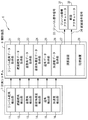
- FIG. 2 is a block diagram schematically showing the configuration of the control system 6 mounted on the spacecraft 10.
- the control system 6 includes a measurement system 7 and a control device 8. *
- the measurement system 7 acquires various observation amounts of the spacecraft 10.
- the measurement system 7 includes a gimbal rudder angle detector 11, a control surface rudder angle detector 12, a posture angle detector 13, a posture angular velocity detector 14, an angle of attack detector 15, and an acceleration detector. 16. *
- the gimbal rudder angle detector 11 detects the gimbal rudder angle of the rocket engine 2 and generates gimbal rudder angle data indicating the detected gimbal rudder angle.
- the control surface control angle detector 12 detects the control angle of the control surface 5, and generates control surface control angle data indicating the detected control angle.
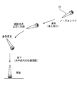
- the attitude angle detector 13 detects the attitude angle of the spacecraft 10 and generates attitude angle data indicating the detected attitude angle.
- the attitude angle ⁇ is defined as an angle between the horizontal plane H and a reference axis 10 a (typically a central axis) defined in the spacecraft 10. . *
- the attitude angular velocity detection unit 14 detects the attitude angular velocity (change amount of the attitude angle per unit time) of the spacecraft 10 and generates attitude angular velocity data indicating the detected attitude angular velocity.
- the angle-of-attack detector 15 detects the angle of attack of the spacecraft 10 and generates angle-of-attack data indicating the detected angle of attack.
- the angle of attack ⁇ is an angle between the reference axis 10 a of the spacecraft 10 and the airspeed vector U (that is, the speed vector of the spacecraft 10 with respect to air). Is defined as *
- the acceleration detector 16 detects the acceleration of the spacecraft 10 and generates acceleration data indicating the detected acceleration.
- the measurement system 7 should just be comprised so that the observation amount required for control of the spacecraft 10 may be acquired.
- the measurement system 7 does not have to include all of the gimbal rudder angle detection unit 11, the control surface rudder angle detection unit 12, the posture angle detection unit 13, the posture angular velocity detection unit 14, the attack angle detection unit 15, and the acceleration detection unit 16. . *
- the control device 8 includes a gimbal mechanism actuator 31 that adjusts the gimbal rudder angle of the rocket engine 2 and an actuator that adjusts aerodynamic characteristics of the aerodynamic elements provided in the spacecraft 10 based on the observation amount acquired by the measurement system 7.
- the control surface actuator 32 that adjusts the control angle of the control surface 5 is controlled.
- the control device 8 includes a gimbal rudder angle data acquisition unit 21, a control surface rudder angle data acquisition unit 22, an attitude angle data acquisition unit 23, an attitude angular velocity data acquisition unit 24, an angle of attack data acquisition unit 25, and acceleration data acquisition.
- a unit 26, an arithmetic device 27, and a storage device 28 are provided. *
- the gimbal rudder angle data acquisition unit 21 acquires gimbal rudder angle data from the gimbal rudder angle detection unit 11.
- the control surface steering angle data acquisition unit 22 acquires control surface steering angle data from the control surface steering angle detection unit 12.
- the posture angle data acquisition unit 23 acquires posture angle data from the posture angle detection unit 13.
- the posture angular velocity data acquisition unit 24 acquires posture angular velocity data from the posture angular velocity detection unit 14.
- the angle of attack data acquisition unit 25 acquires the angle of attack data from the angle of attack detection unit 15.
- the acceleration data acquisition unit 26 acquires acceleration data from the acceleration detection unit 16. *
- the calculation device 27 performs various calculations for controlling the spacecraft 10. For example, in this embodiment, the calculation device 27 operates the amount of operation of the gimbal mechanism actuator 31 based on the acquired gimbal rudder angle data, control surface rudder angle data, attitude angle data, attitude angular velocity data, angle of attack data, and acceleration data. And a control surface operation signal 34 indicating the operation amount of the control surface actuator 32 are generated. As will be described later, in the present embodiment, the operation amounts of the gimbal mechanism actuator 31 and the control surface actuator 32 are calculated by nonlinear optimal control using the stable manifold method.
- the storage device 28 stores various programs and data used for computations by the computation device 27. *
- FIG. 4 is a diagram conceptually showing the landing operation of the spacecraft 10 in the present embodiment.
- the spacecraft 10 launched into space enters the atmosphere by nose entry, that is, from the nose (in this embodiment, the end opposite to the end where the rocket engine 2 of the body 1 is provided).
- the spacecraft 10 After entering the atmosphere, the spacecraft 10 flies while obtaining lift from the atmosphere and reaches the sky above the landing point. Lift is generated using the fins 3 or by the body of the spacecraft 10 itself. After reaching the sky above the landing point (more precisely, after reaching a predetermined setting area preset in the vicinity of the landing point), the spacecraft 10 is configured to make a target attitude angle (most typically The posture is changed to 90 °. After that, the spacecraft 10 descends while adjusting the position in the horizontal plane, and makes a vertical landing at a desired landing point.
- a target attitude angle most typically The posture is changed to 90 °.
- Such a landing operation is suitable for improving the operability of the spacecraft 10. More specifically, according to the landing operation of the present embodiment, the aircraft flies while obtaining lift from the atmosphere and moves to the vicinity of the target landing point, so that the landing point can be freely selected, and vertical landing is performed. Since this is done, the scale of facilities to be provided at the landing point can be reduced. In addition, the direction of thrust is changed by performing a large attitude change (typically a change in attitude angle exceeding 90 °) immediately before landing, and the spacecraft 10 is decelerated, so fuel for deceleration There is also an advantage that consumption can be reduced.
- a large attitude change typically a change in attitude angle exceeding 90 °
- FIG. 5 is a graph conceptually showing an example of the behavior of the spacecraft 10 in the attitude change when the robustness against the disturbance and the convergence of the attitude angle are insufficient. Since there is a large difference between the posture angle at the start of posture change and the target posture angle at the time of vertical landing, a situation occurs in which the posture angle greatly swings in the opposite direction past the target posture angle. For this reason, a situation in which the attitude angle diverges or a situation in which the attitude angle converges only very slowly may occur. *
- the operation amounts of the gimbal mechanism actuator 31 and the control surface actuator 32 are calculated by nonlinear optimal control using the stable manifold method.
- the Stable Manifold Method is one of the methods to calculate the stabilizing solution of the Hamilton-Jacobi equation in the nonlinear optimal control problem.
- the solution is to find a solution on the stable manifold. Note that nonlinear optimal control using the stable manifold method is disclosed, for example, below.
- the problem of calculating the optimum value of the operation amount of the gimbal mechanism actuator 31 and the control surface actuator 32 based on the observation amount acquired by the measurement system 7 can be described as a Hamilton-Jacobi equation.
- the relationship between the observation amount acquired by the measurement system 7 and the operation amount of the gimbal mechanism actuator 31 and the control surface actuator 32 is described by a polynomial or mapping data, and this polynomial is used.
- the amount of operation of the gimbal mechanism actuator 31 and the control surface actuator 32 is calculated from the acquired observation amount by mapping using the mapping data.
- FIG. 4 shows a landing operation when this method is adopted. Specifically, in the attitude change, the attitude angle of the spacecraft 10 is controlled to the target attitude angle at the time of vertical landing, and after the attitude angle is controlled to the target attitude angle, the position of the spacecraft 10 in the horizontal plane is adjusted. The spacecraft 10 is lowered. In the attitude change, the position of the spacecraft 10 in the horizontal plane is not controlled. According to such a method, the difficulty in controlling the posture angle can be reduced.
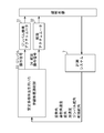
- FIG. 6 is a control block diagram illustrating the control of the attitude angle of the spacecraft 10 in the attitude change.
- the motion of the spacecraft 10 is observed by the measurement system 7, and the observation amount is acquired.
- the attitude angle, the attitude angular velocity, the attack angle, the acceleration, the gimbal rudder angle, and the rudder angle of the control surface 5 are acquired.
- nonlinear optimum control using the stable manifold method is performed, and the gimbal mechanism actuator 31 and the rudder surface actuator 32 operation amounts are respectively calculated, and a gimbal operation signal 33 and a control surface operation signal 34 indicating the calculated operation amount are generated.
- Nonlinear optimal control using this stable manifold method is performed by the arithmetic unit 27.
- the gimbal operation signal 33 and the control surface operation signal 34 are supplied to the gimbal mechanism actuator 31 and the control surface actuator 32, respectively, whereby the gimbal control angle of the rocket engine 2 and the control angle of the control surface 5 are controlled.
- the observation amount acquired by the measurement system 7 includes the angle of attack of the spacecraft 10.
- the influence of the aerodynamic force acting on the spacecraft 10 is large.
- the aerodynamic force acting on the spacecraft 10 strongly depends on the angle of attack (that is, the angle between the air flow and the reference axis 10a of the spacecraft 10). It is effective for realizing good attitude angle control.
- the angle of attack is affected by the direction of air flow, the angle of attack is not a parameter that corresponds completely to the attitude angle.
- the angle-of-attack detection unit 15 that detects the angle of attack.
- the angle of attack may be calculated from other observation amounts. For example, since the angle of attack affects the acceleration of the spacecraft 10, the angle of attack may be calculated based on the acceleration detected by the acceleration detector 16. *
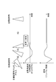
- FIG. 7 is a graph conceptually showing an example of the behavior of the spacecraft 10 when nonlinear optimal control using the stable manifold method is performed at the time of posture change.
- the difference between the posture angle at the start of posture change and the target posture angle at the time of vertical landing is large.
- the convergence is improved by using nonlinear optimal control using the stable manifold method, and the posture angle quickly converges to the target posture angle.
- robustness can be improved by using nonlinear optimal control using a stable manifold method.
Landscapes
- Engineering & Computer Science (AREA)
- Remote Sensing (AREA)
- Aviation & Aerospace Engineering (AREA)
- Chemical & Material Sciences (AREA)
- Combustion & Propulsion (AREA)
- Radar, Positioning & Navigation (AREA)
- Automation & Control Theory (AREA)
- Control Of Position, Course, Altitude, Or Attitude Of Moving Bodies (AREA)
Priority Applications (2)
| Application Number | Priority Date | Filing Date | Title |
|---|---|---|---|
| US16/320,678 US20190161214A1 (en) | 2016-09-08 | 2017-08-04 | Spacecraft and landing method |
| EP17848493.7A EP3480121A4 (en) | 2016-09-08 | 2017-08-04 | SPACING MACHINE AND LANDING METHOD THEREOF |
Applications Claiming Priority (2)
| Application Number | Priority Date | Filing Date | Title |
|---|---|---|---|
| JP2016-175109 | 2016-09-08 | ||
| JP2016175109A JP6720031B2 (ja) | 2016-09-08 | 2016-09-08 | 宇宙機及びその着陸方法 |
Publications (1)
| Publication Number | Publication Date |
|---|---|
| WO2018047549A1 true WO2018047549A1 (ja) | 2018-03-15 |
Family
ID=61562786
Family Applications (1)
| Application Number | Title | Priority Date | Filing Date |
|---|---|---|---|
| PCT/JP2017/028439 Ceased WO2018047549A1 (ja) | 2016-09-08 | 2017-08-04 | 宇宙機及びその着陸方法 |
Country Status (4)
| Country | Link |
|---|---|
| US (1) | US20190161214A1 (enExample) |
| EP (1) | EP3480121A4 (enExample) |
| JP (1) | JP6720031B2 (enExample) |
| WO (1) | WO2018047549A1 (enExample) |
Families Citing this family (10)
| Publication number | Priority date | Publication date | Assignee | Title |
|---|---|---|---|---|
| US10800545B2 (en) * | 2015-02-23 | 2020-10-13 | Advanced Product Development, Llc | Rocket landing system |
| CN109579833B (zh) * | 2018-12-04 | 2020-07-17 | 上海航天控制技术研究所 | 一种对返回式运载火箭的垂直着陆阶段的组合导航方法 |
| CN110667890B (zh) * | 2019-09-10 | 2022-06-28 | 北方信息控制研究院集团有限公司 | 一种空间飞行器非线性姿态稳定方法 |
| WO2021242474A2 (en) * | 2020-05-03 | 2021-12-02 | Advanced Product Development, Llc | Rocket launching and landing system |
| JP7465531B2 (ja) | 2020-07-17 | 2024-04-11 | 国立研究開発法人宇宙航空研究開発機構 | ロケット制御システム、及びロケットの着陸動作の制御方法 |
| CN112249369B (zh) * | 2020-09-28 | 2022-01-04 | 上海航天控制技术研究所 | 一种火箭动力定点着陆制导方法 |
| FR3116512B1 (fr) * | 2020-11-25 | 2024-09-20 | Arianegroup Sas | Système de transport spatial réutilisable |
| CN112525004B (zh) * | 2020-11-27 | 2022-10-18 | 中国人民解放军国防科技大学 | 火箭定点软着陆的开机点在线确定方法及系统 |
| FR3121125B1 (fr) * | 2021-03-23 | 2024-05-03 | Arianegroup Sas | Système de transport hypersonique |
| CN114690793B (zh) * | 2022-03-28 | 2023-01-06 | 北京理工大学 | 基于滑模控制的可重复使用运载火箭垂直软着陆制导方法 |
Citations (6)
| Publication number | Priority date | Publication date | Assignee | Title |
|---|---|---|---|---|
| US20070012820A1 (en) * | 2004-08-11 | 2007-01-18 | David Buehler | Reusable upper stage |
| JP2012530020A (ja) | 2009-06-15 | 2012-11-29 | ブルー オリジン エルエルシー | 宇宙打ち上げ機の海上着陸及び関連のシステム及び方法 |
| US8571727B1 (en) * | 2013-02-06 | 2013-10-29 | The Aerospace Corporation | Energy-angular momentum closed-loop guidance for launch vehicles |
| JP5508017B2 (ja) | 2006-10-20 | 2014-05-28 | アストリウム・エス・エー・エス | 航空力学的および宇宙的飛行を行う飛行機およびそれに関係した操縦方法 |
| JP2016068579A (ja) * | 2014-09-26 | 2016-05-09 | 三菱重工業株式会社 | 垂直離着陸機、及び垂直離着陸機の制御方法 |
| JP2016175109A (ja) | 2015-03-20 | 2016-10-06 | 株式会社キーエンス | レーザマーキング装置、該レーザマーキング装置を用いた印字方法及びコンピュータプログラム |
-
2016
- 2016-09-08 JP JP2016175109A patent/JP6720031B2/ja active Active
-
2017
- 2017-08-04 US US16/320,678 patent/US20190161214A1/en not_active Abandoned
- 2017-08-04 EP EP17848493.7A patent/EP3480121A4/en not_active Withdrawn
- 2017-08-04 WO PCT/JP2017/028439 patent/WO2018047549A1/ja not_active Ceased
Patent Citations (6)
| Publication number | Priority date | Publication date | Assignee | Title |
|---|---|---|---|---|
| US20070012820A1 (en) * | 2004-08-11 | 2007-01-18 | David Buehler | Reusable upper stage |
| JP5508017B2 (ja) | 2006-10-20 | 2014-05-28 | アストリウム・エス・エー・エス | 航空力学的および宇宙的飛行を行う飛行機およびそれに関係した操縦方法 |
| JP2012530020A (ja) | 2009-06-15 | 2012-11-29 | ブルー オリジン エルエルシー | 宇宙打ち上げ機の海上着陸及び関連のシステム及び方法 |
| US8571727B1 (en) * | 2013-02-06 | 2013-10-29 | The Aerospace Corporation | Energy-angular momentum closed-loop guidance for launch vehicles |
| JP2016068579A (ja) * | 2014-09-26 | 2016-05-09 | 三菱重工業株式会社 | 垂直離着陸機、及び垂直離着陸機の制御方法 |
| JP2016175109A (ja) | 2015-03-20 | 2016-10-06 | 株式会社キーエンス | レーザマーキング装置、該レーザマーキング装置を用いた印字方法及びコンピュータプログラム |
Non-Patent Citations (4)
| Title |
|---|
| "The Institute of Systems, Control and Information Engineers", SYSTEMS, CONTROL AND INFORMATION, vol. 7, no. 13, 1996, pages 1 - 6 |
| JOURNAL OF JAPAN SOCIETY FOR AERONAUTICAL AND SPACE SCIENCES, vol. 61, no. 1, 2013, pages 1 - 8 |
| JOURNAL OF THE JAPAN SOCIETY FOR AERONAUTICAL AND SPACE SCIENCES, vol. 61, no. 1, 2013, pages 1 - 8 |
| See also references of EP3480121A4 |
Also Published As
| Publication number | Publication date |
|---|---|
| EP3480121A1 (en) | 2019-05-08 |
| EP3480121A4 (en) | 2020-02-19 |
| US20190161214A1 (en) | 2019-05-30 |
| JP2018039390A (ja) | 2018-03-15 |
| JP6720031B2 (ja) | 2020-07-08 |
Similar Documents
| Publication | Publication Date | Title |
|---|---|---|
| JP6720031B2 (ja) | 宇宙機及びその着陸方法 | |
| US8498756B1 (en) | Movable ground based recovery system for reuseable space flight hardware | |
| Yu et al. | Automatic carrier landing system based on active disturbance rejection control with a novel parameters optimizer | |
| Azinheira et al. | A backstepping controller for path‐tracking of an underactuated autonomous airship | |
| Jung et al. | Development and application of controller for transition flight of tail-sitter UAV | |
| Devalla et al. | Developments in unmanned powered parachute aerial vehicle: A review | |
| US11858626B2 (en) | Autonomous air vehicle delivery system incorporating deployment | |
| US10669047B2 (en) | System and method for hypersonic payload separation | |
| JP2018039390A5 (enExample) | ||
| US10866594B2 (en) | Fuel systems and methods for an aerial vehicle | |
| Jung et al. | A comprehensive flight control design and experiment of a tail-sitter UAV | |
| CN112937832A (zh) | 一种空投式无人机及其抛射方法 | |
| WO2006104838A2 (en) | Lifting body tuned for passive re-entry | |
| Pravitra et al. | Adaptive control for attitude match station-keeping and landing of a fixed-wing UAV onto a maneuvering platform | |
| KR101630680B1 (ko) | 고정익 무인항공기의 수직착륙방법 및 시스템 | |
| Taniguchi | Analysis of deepstall landing for uav | |
| Pezzella et al. | Assessment of hypersonic aerodynamic performance of the EFTV-ESM configuration in the framework of the hexafly-int research project | |
| Baer | F-35A high angle of attack testing | |
| Kawaguchi et al. | Post-flight evaluation of the guidance and control for D-SEND# 2 2nd drop test | |
| US12312082B2 (en) | Propulsion device and associated method for controlling the landing of such a propulsion device | |
| Crowther et al. | Post-stall landing for field retrieval of unmanned air vehicles | |
| Wyllie et al. | Precision parafoil recovery-Providing flexibility for battlefield UAV systems? | |
| Imado et al. | Research on a new aircraft point-mass model | |
| Fujiwara et al. | Flight plan and flight test results of experimental SST vehicle NEXST-1 | |
| Gonzalez et al. | Design of a landing control system which considers dynamic ground effect for an unmanned airplane |
Legal Events
| Date | Code | Title | Description |
|---|---|---|---|
| 121 | Ep: the epo has been informed by wipo that ep was designated in this application |
Ref document number: 17848493 Country of ref document: EP Kind code of ref document: A1 |
|
| ENP | Entry into the national phase |
Ref document number: 2017848493 Country of ref document: EP Effective date: 20190131 |
|
| NENP | Non-entry into the national phase |
Ref country code: DE |