WO2018043350A1 - Filtre de purification de gaz d'échappement - Google Patents
Filtre de purification de gaz d'échappement Download PDFInfo
- Publication number
- WO2018043350A1 WO2018043350A1 PCT/JP2017/030583 JP2017030583W WO2018043350A1 WO 2018043350 A1 WO2018043350 A1 WO 2018043350A1 JP 2017030583 W JP2017030583 W JP 2017030583W WO 2018043350 A1 WO2018043350 A1 WO 2018043350A1
- Authority
- WO
- WIPO (PCT)
- Prior art keywords
- exhaust gas
- gas purification
- purification filter
- cell
- sectional area
- Prior art date
Links
- 238000000746 purification Methods 0.000 title claims abstract description 104
- 210000004027 cell Anatomy 0.000 claims abstract description 135
- 210000002421 cell wall Anatomy 0.000 claims abstract description 69
- 238000011144 upstream manufacturing Methods 0.000 claims abstract description 68
- 239000013618 particulate matter Substances 0.000 claims abstract description 31
- 239000003054 catalyst Substances 0.000 claims description 10
- 230000002093 peripheral effect Effects 0.000 description 32
- 239000011148 porous material Substances 0.000 description 11
- 238000010586 diagram Methods 0.000 description 9
- 239000012466 permeate Substances 0.000 description 8
- 230000004048 modification Effects 0.000 description 7
- 238000012986 modification Methods 0.000 description 7
- 230000005540 biological transmission Effects 0.000 description 5
- 238000002485 combustion reaction Methods 0.000 description 5
- VYPSYNLAJGMNEJ-UHFFFAOYSA-N Silicium dioxide Chemical compound O=[Si]=O VYPSYNLAJGMNEJ-UHFFFAOYSA-N 0.000 description 4
- 238000001914 filtration Methods 0.000 description 4
- 230000007423 decrease Effects 0.000 description 3
- 230000000694 effects Effects 0.000 description 3
- 229910018072 Al 2 O 3 Inorganic materials 0.000 description 2
- 229910004298 SiO 2 Inorganic materials 0.000 description 2
- 229910052878 cordierite Inorganic materials 0.000 description 2
- JSKIRARMQDRGJZ-UHFFFAOYSA-N dimagnesium dioxido-bis[(1-oxido-3-oxo-2,4,6,8,9-pentaoxa-1,3-disila-5,7-dialuminabicyclo[3.3.1]nonan-7-yl)oxy]silane Chemical compound [Mg++].[Mg++].[O-][Si]([O-])(O[Al]1O[Al]2O[Si](=O)O[Si]([O-])(O1)O2)O[Al]1O[Al]2O[Si](=O)O[Si]([O-])(O1)O2 JSKIRARMQDRGJZ-UHFFFAOYSA-N 0.000 description 2
- 238000001035 drying Methods 0.000 description 2
- 238000003754 machining Methods 0.000 description 2
- 239000002994 raw material Substances 0.000 description 2
- 239000000377 silicon dioxide Substances 0.000 description 2
- 239000000126 substance Substances 0.000 description 2
- 239000005995 Aluminium silicate Substances 0.000 description 1
- WNROFYMDJYEPJX-UHFFFAOYSA-K aluminium hydroxide Chemical compound [OH-].[OH-].[OH-].[Al+3] WNROFYMDJYEPJX-UHFFFAOYSA-K 0.000 description 1
- PNEYBMLMFCGWSK-UHFFFAOYSA-N aluminium oxide Inorganic materials [O-2].[O-2].[O-2].[Al+3].[Al+3] PNEYBMLMFCGWSK-UHFFFAOYSA-N 0.000 description 1
- 235000012211 aluminium silicate Nutrition 0.000 description 1
- 239000011230 binding agent Substances 0.000 description 1
- 230000015572 biosynthetic process Effects 0.000 description 1
- 229910010293 ceramic material Inorganic materials 0.000 description 1
- 239000012141 concentrate Substances 0.000 description 1
- 238000011049 filling Methods 0.000 description 1
- 238000010304 firing Methods 0.000 description 1
- NLYAJNPCOHFWQQ-UHFFFAOYSA-N kaolin Chemical compound O.O.O=[Al]O[Si](=O)O[Si](=O)O[Al]=O NLYAJNPCOHFWQQ-UHFFFAOYSA-N 0.000 description 1
- 238000004898 kneading Methods 0.000 description 1
- 239000010687 lubricating oil Substances 0.000 description 1
- 238000004519 manufacturing process Methods 0.000 description 1
- 239000000463 material Substances 0.000 description 1
- 238000009740 moulding (composite fabrication) Methods 0.000 description 1
- 229910052763 palladium Inorganic materials 0.000 description 1
- 229910052697 platinum Inorganic materials 0.000 description 1
- 229910052703 rhodium Inorganic materials 0.000 description 1
- 239000000454 talc Substances 0.000 description 1
- 229910052623 talc Inorganic materials 0.000 description 1
- XLYOFNOQVPJJNP-UHFFFAOYSA-N water Substances O XLYOFNOQVPJJNP-UHFFFAOYSA-N 0.000 description 1
Images


Classifications
-
- B—PERFORMING OPERATIONS; TRANSPORTING
- B01—PHYSICAL OR CHEMICAL PROCESSES OR APPARATUS IN GENERAL
- B01D—SEPARATION
- B01D39/00—Filtering material for liquid or gaseous fluids
- B01D39/14—Other self-supporting filtering material ; Other filtering material
- B01D39/20—Other self-supporting filtering material ; Other filtering material of inorganic material, e.g. asbestos paper, metallic filtering material of non-woven wires
-
- B—PERFORMING OPERATIONS; TRANSPORTING
- B01—PHYSICAL OR CHEMICAL PROCESSES OR APPARATUS IN GENERAL
- B01D—SEPARATION
- B01D46/00—Filters or filtering processes specially modified for separating dispersed particles from gases or vapours
-
- B—PERFORMING OPERATIONS; TRANSPORTING
- B01—PHYSICAL OR CHEMICAL PROCESSES OR APPARATUS IN GENERAL
- B01D—SEPARATION
- B01D53/00—Separation of gases or vapours; Recovering vapours of volatile solvents from gases; Chemical or biological purification of waste gases, e.g. engine exhaust gases, smoke, fumes, flue gases, aerosols
- B01D53/34—Chemical or biological purification of waste gases
- B01D53/92—Chemical or biological purification of waste gases of engine exhaust gases
- B01D53/94—Chemical or biological purification of waste gases of engine exhaust gases by catalytic processes
-
- B01J35/56—
-
- F—MECHANICAL ENGINEERING; LIGHTING; HEATING; WEAPONS; BLASTING
- F01—MACHINES OR ENGINES IN GENERAL; ENGINE PLANTS IN GENERAL; STEAM ENGINES
- F01N—GAS-FLOW SILENCERS OR EXHAUST APPARATUS FOR MACHINES OR ENGINES IN GENERAL; GAS-FLOW SILENCERS OR EXHAUST APPARATUS FOR INTERNAL COMBUSTION ENGINES
- F01N3/00—Exhaust or silencing apparatus having means for purifying, rendering innocuous, or otherwise treating exhaust
- F01N3/02—Exhaust or silencing apparatus having means for purifying, rendering innocuous, or otherwise treating exhaust for cooling, or for removing solid constituents of, exhaust
- F01N3/021—Exhaust or silencing apparatus having means for purifying, rendering innocuous, or otherwise treating exhaust for cooling, or for removing solid constituents of, exhaust by means of filters
- F01N3/022—Exhaust or silencing apparatus having means for purifying, rendering innocuous, or otherwise treating exhaust for cooling, or for removing solid constituents of, exhaust by means of filters characterised by specially adapted filtering structure, e.g. honeycomb, mesh or fibrous
-
- F—MECHANICAL ENGINEERING; LIGHTING; HEATING; WEAPONS; BLASTING
- F01—MACHINES OR ENGINES IN GENERAL; ENGINE PLANTS IN GENERAL; STEAM ENGINES
- F01N—GAS-FLOW SILENCERS OR EXHAUST APPARATUS FOR MACHINES OR ENGINES IN GENERAL; GAS-FLOW SILENCERS OR EXHAUST APPARATUS FOR INTERNAL COMBUSTION ENGINES
- F01N3/00—Exhaust or silencing apparatus having means for purifying, rendering innocuous, or otherwise treating exhaust
- F01N3/02—Exhaust or silencing apparatus having means for purifying, rendering innocuous, or otherwise treating exhaust for cooling, or for removing solid constituents of, exhaust
- F01N3/021—Exhaust or silencing apparatus having means for purifying, rendering innocuous, or otherwise treating exhaust for cooling, or for removing solid constituents of, exhaust by means of filters
- F01N3/033—Exhaust or silencing apparatus having means for purifying, rendering innocuous, or otherwise treating exhaust for cooling, or for removing solid constituents of, exhaust by means of filters in combination with other devices
- F01N3/035—Exhaust or silencing apparatus having means for purifying, rendering innocuous, or otherwise treating exhaust for cooling, or for removing solid constituents of, exhaust by means of filters in combination with other devices with catalytic reactors, e.g. catalysed diesel particulate filters
Definitions
- the present disclosure relates to an exhaust gas purification filter for purifying exhaust gas of an internal combustion engine.
- the exhaust pipe of the internal combustion engine is provided with an exhaust gas purification device that collects particulate matter (PM) contained in the exhaust gas.
- PM particulate matter
- Some of the exhaust gas purifying apparatuses include an exhaust gas purifying filter for collecting particulate matter contained in the exhaust gas as disclosed in Patent Document 1.
- the exhaust gas purification filter described in Patent Document 1 has a plurality of cell walls and cell holes formed surrounded by the cell walls. Some of the plurality of cell holes are upstream plugging cell holes whose upstream end faces are blocked by plug parts, and the other part are downstream plugging whose downstream end faces are blocked by plug parts. It is a cell hole.
- the exhaust gas purification filter described in Patent Document 1 is configured to allow exhaust gas to flow in from the downstream plugging cell hole, to reliably permeate the exhaust gas that has flowed into the cell wall, and to discharge from the upstream plugging cell. Yes.
- the exhaust gas purification filter collects particulate matter in the exhaust gas on the cell wall by allowing the exhaust gas to permeate the cell wall. Thereby, the exhaust gas purification filter removes particulate matter from the exhaust gas.
- the flow passage cross-sectional area of the upstream plugging cell hole is formed larger than the flow passage cross-sectional area of the downstream plugging cell hole in order to reduce the pressure loss of the exhaust gas.
- This disclosure intends to provide an exhaust gas purification filter capable of improving the collection rate of particulate matter by effectively utilizing the cell wall from the viewpoint of particulate matter collection.
- a first aspect of the present disclosure is an exhaust gas purification filter for collecting particulate matter in exhaust gas, A plurality of cell walls, and a plurality of cell holes surrounded by the plurality of cell walls, As the cell hole, a downstream plugging cell hole whose downstream end is closed by a plug part and whose upstream side is opened, and an upstream plugging cell whose upstream end part is closed by a plug part and whose downstream side is opened A hole, and The ratio of the channel cross-sectional area S2 to the channel cross-sectional area S1 when the channel cross-sectional area of one downstream plugging cell hole is S1, and the channel cross-sectional area of the one upstream plugging cell hole is S2.
- the flow path cross-sectional area ratio R S2 / S1 satisfies 1.7 ⁇ R ⁇ 3.0. Therefore, the flow velocity of the exhaust gas passing through the cell wall can be equalized in the axial direction of the exhaust gas purification filter. Thereby, it can suppress that permeation
- an exhaust gas purification filter capable of improving the collection rate of particulate matter by effectively utilizing the cell wall from the viewpoint of particulate matter collection.
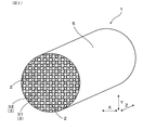
- FIG. 1 is a perspective view of an exhaust gas purification filter in Embodiment 1.
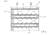
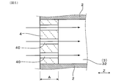
- FIG. 2 is a cross-sectional view parallel to the axial direction of the exhaust gas purification filter in Embodiment 1
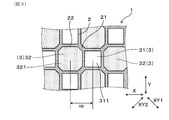
- FIG. 3 is an enlarged view of the exhaust gas purification filter according to the first embodiment when viewed from the axial direction.
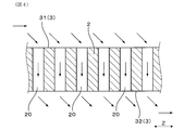
- FIG. 4 is a schematic cross-sectional view for explaining the pores of the cell wall in the first embodiment.
- FIG. 5 is a schematic cross-sectional view for explaining the pores of the plug portion in Embodiment 1.
- FIG. 6 is a diagram showing a modification of the first embodiment, and is an enlarged view of the exhaust gas purification filter viewed from the axial direction
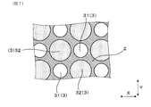
- FIG. 7 is a diagram showing another modification of the first embodiment, and is an enlarged view of the exhaust gas purification filter as viewed from the axial direction
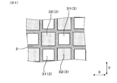
- FIG. 8 is a diagram showing still another modification of the first embodiment, and is an enlarged view of the exhaust gas purification filter viewed from the axial direction
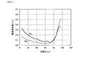
- FIG. 9 is a diagram showing the relationship between the position and the wall permeation flow velocity in Experimental Example 1
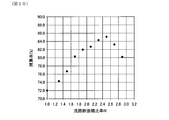
- FIG. 10 is a diagram showing the relationship between the flow path cross-sectional area ratio R and the collection rate in Experimental Example 2.
- FIG. 11 is a view of the exhaust gas purification filter in the second embodiment as seen from the axial direction.
- FIG. 11 is a view of the exhaust gas purification filter in the second embodiment as seen from the axial direction.
- FIG. 12 is an enlarged view of the periphery of the boundary line in FIG.
- FIG. 13 is a view showing a modification of the second embodiment, and is a view of the exhaust gas purification filter viewed from the axial direction.
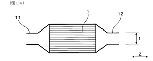
- FIG. 14 is a diagram illustrating a modification of the second embodiment, and is a schematic diagram illustrating a state where an exhaust gas purification filter is attached to a pipe.
- the exhaust gas purification filter 1 of this embodiment collects particulate matter in exhaust gas. As shown in FIGS. 1 and 2, the exhaust gas purification filter 1 has a plurality of cell walls 2 and a plurality of cell holes 3 surrounded by the plurality of cell walls 2.
- the exhaust gas purification filter 1 includes, as cell holes 3, downstream plugged cell holes 31 whose downstream ends are closed by plug portions 4 and opened upstream, and upstream ends are plug portions. And an upstream plugging cell hole 32 which is closed by 4 and opened on the downstream side.
- the flow path cross-sectional area of one downstream plugging cell hole 31 is S1
- the flow path cross-sectional area of one upstream plugging cell hole 32 is S2.
- the channel cross-sectional area ratio R S2 / S1, which is the ratio of the channel cross-sectional area S2 to the channel cross-sectional area S1, satisfies 1.7 ⁇ R ⁇ 3.0.
- the flow passage cross-sectional area S1 of one downstream plugging cell hole 31 is the one downstream plugging cell hole orthogonal to the axial direction Z of the exhaust gas purification filter 1.
- 31 is the area of the cross section 311 of 31.
- the flow passage cross-sectional area of one upstream plugging cell hole 32 is the area of the cross section 321 of the upstream plugging cell hole 32 perpendicular to the axial direction Z of the exhaust gas purification filter 1.
- the exhaust gas purification filter 1 can be used for purification of exhaust gas generated in an internal combustion engine of a car, for example, a diesel engine or a gasoline engine.
- the exhaust gas purification filter 1 is used by being attached to an exhaust pipe of an internal combustion engine.
- the axial direction of the exhaust gas purification filter 1 is simply referred to as the axial direction Z.
- the side where the exhaust gas is introduced of the exhaust gas purification filter 1 attached to the internal combustion engine is referred to as the upstream side, and the side where the exhaust gas is discharged is referred to as the downstream side. 2, 4, 5, and the like indicate the main exhaust gas flow when the exhaust gas purification filter 1 is used.
- the exhaust gas purification filter 1 has a cylindrical shape.
- the exhaust gas purification filter 1 includes an outer peripheral portion 5 formed in a cylindrical shape, cell walls 2 arranged in a lattice shape on the inner peripheral side of the outer peripheral portion 5, and a plurality of cell holes 3.
- the cell hole 3 facing the outer peripheral portion 5 is variously changed in shape and flow path cross-sectional area from the other cell holes 3. Therefore, in this specification, unless otherwise specified, the cell hole 3 means a cell hole other than the cell hole facing the outer peripheral portion 5.
- the cell hole 3 has a downstream plugging cell hole 31 and an upstream plugging cell hole 32.
- the downstream plugging cell hole 31 and the upstream plugging cell hole 32 are both in the axial direction Z and the horizontal direction X even in one direction orthogonal to the axial direction Z (hereinafter referred to as the horizontal direction X). Also in one direction orthogonal to (hereinafter, referred to as the longitudinal direction Y), they are alternately arranged so as to be adjacent to each other.
- the downstream plugging cell hole 31 and the upstream plugging cell hole 32 are arranged in a check pattern.
- the upstream plugging cell holes 32 are arranged to be adjacent to each other in the oblique directions XY1 and XY2 that are orthogonal to the axial direction Z and inclined by 45 ° with respect to both the horizontal direction X and the vertical direction Y. It is out.
- the thickness dimension of the portion 21 between the upstream plugging cell holes 32 adjacent to each other in the oblique directions XY1 and XY2 in the cell wall 2 is the same as the downstream plugging cell hole 31 adjacent to the horizontal direction X or the vertical direction Y in the cell wall 2 and the upstream plug. It is larger than the thickness dimension of the part 22 between the filling cell holes 32.
- the plurality of cell holes 3 have two or more types of shapes. That is, two or more types of cell holes 3 having different shapes when viewed from the axial direction Z are present in the plurality of cell holes 3.
- the cell hole 3 is composed of an octagonal cell hole 3 with an inner peripheral shape and a cell hole 3 with an inner peripheral shape of a quadrangle.
- a cell hole 3 having an octagonal inner periphery is an upstream plugging cell hole 32, and a cell hole 3 having an inner peripheral shape is a square is a downstream plugging cell hole 31.
- the upstream plugging cell hole 32 has an octagonal shape with a 1/4 rotation symmetry
- the downstream plugging cell hole 31 has a square shape.
- the shape of each cell hole 3 may be a shape in which some curves or tapers are formed at the corners.
- the quadrangular shape (square shape) and the octagonal shape are concepts including such a shape.
- the channel cross-sectional area ratio R which is the ratio of the channel cross-sectional area S2 of the upstream plugging cell hole 32 to the channel cross-sectional area S1 of the downstream plugging cell hole 31, is 1.7 ⁇ R ⁇ 3.0. Meet.
- the channel cross-sectional area ratio R is, for example, the average of the channel cross-sectional areas of the five randomly selected downstream plugging cell holes 31 and the channel of the five randomly selected upstream plugging cell holes 32. It can be calculated from the average value of the cross-sectional areas. Further, the flow path cross-sectional area ratio R is not limited to this.
- the flow path cross-sectional area ratio R is determined from the flow path cross-sectional areas in the downstream plugging cell hole 31 and the upstream plugging cell hole 32 adjacent to each other in the horizontal direction X or the vertical direction Y It may be calculated.
- the channel cross-sectional area ratio R further satisfies R ⁇ 2.5. That is, in the present embodiment, the flow path cross-sectional area ratio R satisfies 1.7 ⁇ R ⁇ 2.5.
- the flow path cross-sectional area S1 of the downstream plugged cell hole 31 satisfies 0.5 mm 2 ⁇ S1 ⁇ 3.0 mm 2 .
- the total sum Sa of the channel cross-sectional areas of all the downstream plugging cell holes 31 satisfies 7 cm 2 ⁇ Sa ⁇ 100 cm 2 .
- the exhaust gas purification filter 1 has a constant cell pitch cp both in the vertical direction Y and in the horizontal direction X.
- the cell pitch cp is calculated by (length of downstream plugged cell hole 31/2) + (thickness of cell wall 2) + (length of upstream plugged cell hole 32).
- the cell pitch cp is 1.505 mm.
- the cell wall 2 has a thickness of 0.24 mm.
- the average pore diameter of the cell wall 2 is 15 ⁇ m.
- the porosity of the cell wall 2 is 63%.
- the plug portion 4 is composed mainly of cordierite having a SiO 2 content of 45 to 55 wt%, an Al 2 O 3 content of 33 to 42 wt%, and an MgO content of 12 to 18 wt%.
- the plug portion 4 is arranged so as to close the end portion of the cell hole 3 in the axial direction Z.
- the plug portion 4 is formed with pores 40 communicating from the upstream end to the downstream end.
- the schematic diagram of the pore of the plug part 4 is represented.
- the plug portion 4 has a porosity of 50% to 70%.
- the length A of the plug portion 4 that closes the upstream plugged cell hole 32 in the axial direction Z and the flow path cross-sectional area ratio R have a relationship of 1.0 mm ⁇ A ⁇ (6.0 / R) mm. Fulfill.
- the relationship between the length AA of the plug portion 4 that closes the downstream plugged cell hole 32 and the flow path cross-sectional area ratio R is also 1.0 mm ⁇ AA ⁇ (6.0 / R) mm.
- the cell wall 2 is made of a ceramic material having a porous structure.
- the cell wall 2 has cordierite having a SiO 2 content of 45 to 55 wt%, an Al 2 O 3 content of 33 to 42 wt%, and an MgO content of 12 to 18 wt%. Is the main component.
- the cell wall 2 can be comprised from the material which mixed at least 3 types of the raw material of a kaolin, a silica, porous silica, a talc, aluminum hydroxide, and an alumina at least.
- the cell wall 2 and the plug part 4 can be obtained by adding water, lubricating oil, a binder, etc.
- a plurality of pores 20 that communicate between adjacent cell holes 3 are formed inside the cell wall 2.
- the schematic diagram of the pore 20 is shown.
- many of the plurality of pores 20 have the same inner diameter.
- the total length L of the exhaust gas purification filter 1 in the axial direction Z satisfies 50 mm ⁇ L ⁇ 200 mm. In the present embodiment, the total length L of the exhaust gas purification filter 1 is 100 mm. Moreover, the diameter D of the exhaust gas purification filter 1 satisfies 80 mm ⁇ D ⁇ 200 mm. In this embodiment, the diameter D of the exhaust gas purification filter 1 is 129 mm.
- the flow path cross-sectional area ratio R S2 / S1 satisfies 1.7 ⁇ R ⁇ 3.0. Therefore, the flow rate of the exhaust gas passing through the cell wall 2 can be equalized in the axial direction Z of the exhaust gas purification filter 1. Thereby, permeation
- transmission of exhaust gas can be suppressed to a part of cell wall 2 in the axial direction Z of the exhaust gas purification filter 1. Therefore, in the exhaust gas purification filter 1, the cell wall 2 can be effectively used from the viewpoint of collecting particulate matter, and the filtration area can be increased as a whole. As a result, the collection rate of particulate matter can be improved.
- the collection rate of the particulate matter in the exhaust gas purification filter 1 may be simply referred to as “collection rate”.
- the channel cross-sectional area ratio R further satisfies R ⁇ 2.5. Therefore, the value of the flow path cross-sectional area ratio R has changed due to the dimensional error of the cell wall 2 when the exhaust gas purification filter 1 is formed by die processing, the shrinkage of the exhaust gas purification filter 1 generated during drying and firing, and the like. Sometimes, the collection rate can be prevented from greatly fluctuating. Thereby, the required dimensional tolerance of the cell wall 2 can be easily increased, and the exhaust gas purification filter 1 can be easily manufactured.
- the length A of the plug portion 4 that closes the upstream plugged cell hole 32 in the axial direction Z and the flow path cross-sectional area ratio R have a relationship of 1.0 mm ⁇ A ⁇ (6.0 / R) mm. Fulfill.
- the connectivity between the cell wall 2 and the plug part 4 is increased, and the strength of the exhaust gas purification filter 1 can be improved.
- the length A of the plug portion 4 is less than 1.0 mm, the connectivity between the cell wall 2 and the plug portion 4 tends to deteriorate, and the strength of the exhaust gas purification filter 1 tends to decrease accordingly.
- the length A of the plug portion 4 is set to (6.0 / R) mm or less, it is easy to ensure the collection rate even when the value of the channel cross-sectional area ratio R is relatively large. That is, when the value of the flow path cross-sectional area ratio R is relatively large, the exhaust gas tends to permeate the cell wall 2 in a concentrated manner on the upstream side of the cell wall 2. Therefore, when the flow path cross-sectional area ratio R is relatively large, the length A of the plug portion 4 is shortened to allow the exhaust gas to permeate the plug portion 4 and trap particulate matter in the plug portion 4. Can be collected. As a result, it is easy to ensure the collection rate even when the value of the channel cross-sectional area ratio R is relatively large.
- the exhaust gas is difficult to permeate the plug portion 4, so that the collection is performed when the value of the channel cross-sectional area ratio R is relatively large. It is difficult to secure the rate.
- an exhaust gas purification filter that can improve the collection rate of particulate matter by effectively utilizing the cell wall from the viewpoint of particulate matter collection.
- the shape of the downstream plugging cell hole 31 and the upstream plugging cell hole 32 is not necessarily limited to a combination of a square shape and an octagonal shape.
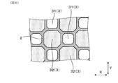
- the shapes of the downstream plugging cell holes 31 and the upstream plugging cell holes 32 may be octagonal shapes.
- the shapes of the downstream plugging cell hole 31 and the upstream plugging cell hole 32 may be circular.
- the downstream plugged cell hole 31 and the upstream plugged cell hole 32 may both be square, but in this case, the cell wall 2 on the diagonal line of the upstream plugged cell hole 32.
- the strength tends to decrease.
- the shape of the downstream plugging cell hole 31 and the upstream plugging cell hole 32 is a combination of a square shape and an octagonal shape as shown in FIG. 3, or as shown in FIG. An octagonal shape is preferred.
- the square shape shown in FIG. 3 is compared to the configuration shown in FIG. 7 where the downstream plugging cell hole 31 and the upstream plugging cell hole 32 are both circular. It is preferable to use a combination of a shape and an octagon shape, or a combination of octagon shapes as shown in FIG.
- Example 1 the flow rate of the exhaust gas that permeates the cell wall 2 is analyzed for each position in the axial direction Z on the cell wall 2.
- the flow rate of the exhaust gas that permeates the cell wall 2 in the exhaust gas purification filter may be referred to as a wall permeation flow rate.
- two exhaust gas purification filters having the same basic structure as that of the first embodiment but having different flow path cross-sectional area ratios R are assumed. Specifically, a sample 1 with a channel cross-sectional area ratio R of 1 and a sample 2 with a channel cross-sectional area ratio R of 1.7 were assumed. That is, the sample 2 is the exhaust gas purification filter 1 in which the flow path cross-sectional area ratio R satisfies 1.7 ⁇ R ⁇ 3.0.
- FIG. 9 The results are shown in FIG. 9, the result of the sample 1 is represented by a broken line BL, and the result of the sample 2 is represented by a solid line SL. Further, the position z shown on the horizontal axis in FIG. 9 indicates the length in the axial direction Z from the upstream end of each sample.
- the sample 1 with the flow path cross-sectional area ratio R of 1 has a wall permeation flow velocity in the downstream end region where the position z is around 80 to 100 mm compared to the region upstream of the downstream end region. It can be seen that it is much larger. That is, it can be seen that the sample 1 is concentrated in the downstream end region of the exhaust gas purification filter in the axial direction Z and the exhaust gas is transmitted through the cell wall.
- Sample 2 with a flow path cross-sectional area ratio R of 1.7 has a reduced wall permeation flow velocity in the downstream end region compared to Sample 1, and accordingly, more upstream than the downstream end region.
- the wall permeation flow velocity can be secured in the region of.
- the sample 2 can equalize the wall permeation
- the exhaust gas flows straight along the axial direction Z from the upstream end of the downstream plugging cell hole 31.
- Example 2 This example is an example of examining the influence on the collection rate when the flow path cross-sectional area ratio R is changed in the exhaust gas purification filter.
- each sample had an overall length L in the axial direction Z of 100 m, a diameter D of 129 mm, a cell pitch cp of 1.505 mm, a thickness of the cell wall 2 of 0.24 mm, an average pore diameter of 15 ⁇ m, and a porosity of 63%.
- each sample was attached to an exhaust pipe of an engine, and exhaust gas was circulated through each sample at a temperature of 450 ° C. and a flow rate of 2.76 m 3 / min.
- the collection rate In calculating the collection rate, the number of particulate matter contained in the exhaust gas introduced into each sample and the number of particulate matter contained in the exhaust gas discharged from each sample were measured. And the collection rate was obtained by calculating the ratio of the number of the particulate matter contained in the exhaust gas discharged from each sample to the number of the particulate matter contained in the exhaust gas introduced into each sample. The results are shown in FIG.
- a sample satisfying a flow path cross-sectional area ratio R of 1.7 ⁇ R ⁇ 3.0 has a higher collection rate than a sample having another flow path cross-sectional area ratio R.
- the flow path cross-sectional area ratio R is less than 1.7, it can be seen that the collection rate rapidly decreases. Therefore, it can be seen that the flow path cross-sectional area ratio R preferably satisfies 1.7 ⁇ R ⁇ 3.0 from the viewpoint of securing the collection rate.
- the present embodiment is an embodiment in which the cell wall 2 carries a catalyst.
- the plug portion 4 also carries a catalyst. By supporting the catalyst on the cell wall 2 and the plug portion 4, harmful substances contained in the exhaust gas can be removed.
- the catalyst is a three-way catalyst containing at least one of Pt, Rh, and Pd.
- the exhaust gas purification filter 1 of the present embodiment is the same as the exhaust gas purification filter shown in the first embodiment, with a catalyst supported thereon.
- the exhaust gas purification filter 1 of this example includes the surface of the cell wall 2 facing the downstream plugging cell hole 31 and the upstream plugging cell hole 32 in Embodiment 1, and the surface of the pore 20 of the cell wall 2.
- the surface of the plug part 4 and the surface of the pore 40 of the plug part 4 are coated with a catalyst. Note that the reference numerals described in the present embodiment indicate the correspondence with FIGS. 1 to 5 of the first embodiment.
- the present embodiment has a center side region 6 including the central axis of the exhaust gas purification filter 1 and an outer peripheral side region 7 disposed on the outer peripheral side of the central side region 6.
- the shape of the downstream plugged cell hole 31 is changed between the central region 6 and the outer peripheral region 7.
- the flow passage cross-sectional area of the downstream plugging cell hole 31 in the outer peripheral region 7 is made larger than the flow passage cross-sectional area of the downstream plugging cell hole 31 in the central region 6. Yes.
- the exhaust gas purification filter 1 has a constant cell pitch over the central region 6 and the outer peripheral region 7. Therefore, the difference in the flow path cross-sectional area of the downstream plugged cell hole 31 between the center side region 6 and the outer peripheral side region 7 is constituted by the difference in the thickness of the cell wall 2. That is, the cell wall 2 is formed so that the outer peripheral side region 7 is thinner than the central side region 6.
- S1o is a flow path cross-sectional area of one downstream plugged cell hole 31 in the outer peripheral side region 7. That is, as shown in FIG. 12, the area of the cross section 311o orthogonal to the axial direction Z in one downstream plugged cell hole 31 in the outer peripheral side region 7 is S1o. And let the flow-path cross-sectional area of the one upstream plugging cell hole 32 in the outer peripheral side area
- region 7 be S2. That is, the area of the cross section 321o orthogonal to the axial direction Z in one upstream plugging cell hole 32 in the outer peripheral side region 7 is S2o.
- the flow path cross-sectional area of one downstream plugged cell hole 31 in the central region 6 is defined as S1c. That is, the area of the cross section 311c orthogonal to the axial direction Z in one downstream plugged cell hole 31 in the center side region 6 is S1c. And let the flow-path cross-sectional area of the one upstream plugging cell hole 32 in the center side area
- region 6 be S2. That is, the area of the cross section 321c orthogonal to the axial direction Z in one upstream plugging cell hole 32 in the central region 6 is S2c.
- the channel cross-sectional area ratio Ro in the outer peripheral side region 7 is smaller than the channel cross-sectional area ratio Rc in the central side region.
- the flow path cross-sectional area ratio Rc in the center side region 6 and the flow path cross-sectional area ratio Ro in the outer peripheral side region 7 are in the range of 1.7 to 3.0, respectively.
- the channel cross-sectional area S2o is larger than the channel cross-sectional area S1c.
- the present invention is not limited to this, and if each of the above-described channel cross-sectional area ratios Rc and Ro is within the range of 1.7 to 3.0, the channel cross-sectional area S2o is the channel cross-sectional area. It is possible to adopt a configuration smaller than S1c or the same configuration as the flow path cross-sectional area S1c.
- the boundary line B between the central region 6 and the outer peripheral region 7 has an octagonal shape.
- the boundary line B is formed in an octagonal shape that is a 1/4 rotation target.
- the boundary line B is shown as a line drawn so as to connect a plurality of downstream plugged cell holes 31 arranged at the inner peripheral end in the outer peripheral side region 7. It may be a line drawn so as to connect a plurality of downstream plugging cell holes 31 or upstream plugging cell holes 32 arranged at the outer peripheral edge in the side region 6. This is because all of them are similar in shape, and the shape is the same regardless of which boundary line B is selected. Others are the same as in the first embodiment.
- the exhaust gas flow rate is possible to prevent the exhaust gas flow rate from being biased in the radial direction of the exhaust gas purification filter 1. That is, generally, when exhaust gas is introduced along the axial direction Z with respect to the exhaust gas purification filter 1 disposed in the exhaust gas flow path, the flow velocity near the central axis tends to increase. Therefore, in the present embodiment, the flow passage cross-sectional area of the downstream plugging cell hole 31 in the outer peripheral side region 7 where the exhaust gas does not easily flow is made larger than the flow passage cross-sectional area of the downstream plugging cell hole 31 in the central region. Yes. Thereby, compared with the exhaust gas purification filter 1 having a uniform cell structure, the exhaust gas can easily flow to the outer peripheral region 7.
- the cell wall 2 can be effectively used in both the outer peripheral side region 7 and the central side region, and the filtration area can be increased as a whole. As a result, it is easy to improve the collection rate of the particulate matter. In addition, the same effects as those of the first embodiment are obtained.
- the shape of the boundary line B is not limited to an octagonal shape, and may be a rectangular shape as shown in FIG. 13, for example.
- the boundary line B has a quadrangular shape, it is particularly preferable to have a square shape.
- the boundary line B has a quadrangular shape, particularly a square shape, the exhaust gas purification filter 1 can be easily manufactured. That is, when the die for forming the exhaust gas purification filter 1 is subjected to electric discharge machining, the shape of the electrode for electric discharge machining can be unified into a quadrangle. As a result, manufacture of the exhaust gas purification filter 1 can be facilitated.
- the boundary line B has an octagonal shape
- the distance between the boundary line B and the outer peripheral portion 5 is less likely to vary depending on the position in the circumferential direction. As a result, it is easy to increase the load resistance when the exhaust gas purification filter 1 is installed in the pipe.
- the boundary line B is preferably sized and shaped so that its inscribed circle is equal to or larger than the inner diameter of the upstream and downstream piping of the exhaust gas purification filter 1. That is, the exhaust gas purification filter 1 is disposed in the pipes 11 and 12 as shown in FIG. Pipes 11 and 12 having an inner diameter I smaller than the outer diameter of the exhaust gas purification filter 1 are connected to the upstream side and the downstream side of the portion where the exhaust gas purification filter 1 is disposed.
- the diameter of the inscribed circle of the boundary line B is preferably set to be equal to or larger than the inner diameter I of the pipes 11 and 12 on the upstream side and the downstream side of the exhaust gas purification filter 1. In particular, when viewed from the axial direction Z, it is preferable that the inner peripheral contours of the pipes 11 and 12 be inside the boundary line B.
- the diameter of the inscribed circle of the boundary line B is preferably 3/4 or less of the diameter of the exhaust gas purification filter 1.
- boundary line B is not necessarily formed in a point-symmetric shape and position around the central axis of the exhaust gas purification filter 1.
- the position and shape of the boundary line B can be appropriately changed according to the relationship between the exhaust gas purification filter 1 and the relative positions of the upstream and downstream pipes 11 and 12.
Abstract
L'invention concerne un filtre de purification de gaz d'échappement qui peut améliorer le taux de collecte de matière particulaire en utilisant efficacement des parois cellulaires à partir du point de vue de la collecte de matière particulaire. Un filtre de purification de gaz d'échappement (1) est destiné à collecter une matière particulaire dans un gaz d'échappement. Le filtre de purification de gaz d'échappement (1) a une pluralité de parois cellulaires (2) et une pluralité de trous cellulaires (3) entourés par la pluralité de parois cellulaires (2). Pour des trous cellulaires (3), le filtre de purification de gaz d'échappement (1) comporte des trous cellulaires bouchés en aval (31), l'extrémité côté aval étant fermée par une partie de bouchon et le côté en amont étant ouvert et des trous cellulaires bouchés en amont (32) l'extrémité côté amont étant fermée par une partie bouchon et le côté aval étant ouvert. Si S1 est la surface de section transversale de trajet d'écoulement pour un trou cellulaire bouché en aval (31) dans un emplacement et laisser S2 la surface de section transversale de trajet d'écoulement pour un trou cellulaire bouché en amont (32) à un emplacement, la proportion de surface de section transversale de trajet d'écoulement R = S2/S1, qui est la proportion de la surface de section transversale de trajet d'écoulement S2 à la surface de section transversale de trajet d'écoulement S1, satisfait 1,7 ≤ R ≤ 3,0.
Applications Claiming Priority (2)
| Application Number | Priority Date | Filing Date | Title |
|---|---|---|---|
| JP2016-172963 | 2016-09-05 | ||
| JP2016172963A JP2018038941A (ja) | 2016-09-05 | 2016-09-05 | 排ガス浄化フィルタ |
Publications (1)
| Publication Number | Publication Date |
|---|---|
| WO2018043350A1 true WO2018043350A1 (fr) | 2018-03-08 |
Family
ID=61301468
Family Applications (1)
| Application Number | Title | Priority Date | Filing Date |
|---|---|---|---|
| PCT/JP2017/030583 WO2018043350A1 (fr) | 2016-09-05 | 2017-08-25 | Filtre de purification de gaz d'échappement |
Country Status (2)
| Country | Link |
|---|---|
| JP (1) | JP2018038941A (fr) |
| WO (1) | WO2018043350A1 (fr) |
Families Citing this family (1)
| Publication number | Priority date | Publication date | Assignee | Title |
|---|---|---|---|---|
| JP6934702B2 (ja) | 2015-03-27 | 2021-09-15 | 株式会社デンソー | 排ガス浄化フィルタ |
Citations (6)
| Publication number | Priority date | Publication date | Assignee | Title |
|---|---|---|---|---|
| WO2004024294A1 (fr) * | 2002-09-13 | 2004-03-25 | Ibiden Co., Ltd. | Filtre |
| JP2006305503A (ja) * | 2005-04-28 | 2006-11-09 | Hitachi Metals Ltd | セラミックハニカムフィルタ |
| WO2011042976A1 (fr) * | 2009-10-08 | 2011-04-14 | イビデン株式会社 | Appareil et procédé de purification des gaz d'échappement |
| JP2015029941A (ja) * | 2013-07-31 | 2015-02-16 | イビデン株式会社 | ハニカムフィルタ |
| WO2016111287A1 (fr) * | 2015-01-09 | 2016-07-14 | 株式会社デンソー | Filtre de gaz d'échappement |
| JP2016130510A (ja) * | 2015-01-09 | 2016-07-21 | 株式会社デンソー | 排ガスフィルタ |
Family Cites Families (3)
| Publication number | Priority date | Publication date | Assignee | Title |
|---|---|---|---|---|
| DE602004006204T2 (de) * | 2003-06-23 | 2008-01-10 | Ibiden Co., Ltd., Ogaki | Wabenstrukturkörper |
| JP2011098335A (ja) * | 2009-10-08 | 2011-05-19 | Ibiden Co Ltd | 排ガス浄化装置及び排ガス浄化方法 |
| JP5713760B2 (ja) * | 2011-03-31 | 2015-05-07 | 日本碍子株式会社 | セラミックスフィルタ |
-
2016
- 2016-09-05 JP JP2016172963A patent/JP2018038941A/ja active Pending
-
2017
- 2017-08-25 WO PCT/JP2017/030583 patent/WO2018043350A1/fr active Application Filing
Patent Citations (6)
| Publication number | Priority date | Publication date | Assignee | Title |
|---|---|---|---|---|
| WO2004024294A1 (fr) * | 2002-09-13 | 2004-03-25 | Ibiden Co., Ltd. | Filtre |
| JP2006305503A (ja) * | 2005-04-28 | 2006-11-09 | Hitachi Metals Ltd | セラミックハニカムフィルタ |
| WO2011042976A1 (fr) * | 2009-10-08 | 2011-04-14 | イビデン株式会社 | Appareil et procédé de purification des gaz d'échappement |
| JP2015029941A (ja) * | 2013-07-31 | 2015-02-16 | イビデン株式会社 | ハニカムフィルタ |
| WO2016111287A1 (fr) * | 2015-01-09 | 2016-07-14 | 株式会社デンソー | Filtre de gaz d'échappement |
| JP2016130510A (ja) * | 2015-01-09 | 2016-07-21 | 株式会社デンソー | 排ガスフィルタ |
Also Published As
| Publication number | Publication date |
|---|---|
| JP2018038941A (ja) | 2018-03-15 |
Similar Documents
| Publication | Publication Date | Title |
|---|---|---|
| US9080484B2 (en) | Wall flow type exhaust gas purification filter | |
| JP4673084B2 (ja) | ハニカムフィルタ及び排ガス処理装置 | |
| JP6838641B2 (ja) | 排ガス浄化装置 | |
| KR101264454B1 (ko) | 내부 공동을 구비한 허니콤 | |
| US20180214810A1 (en) | Plugged honeycomb structure | |
| WO2015022937A1 (fr) | Filtre à particules | |
| JP6238791B2 (ja) | 目封止ハニカム構造体 | |
| CN110314455B (zh) | 蜂窝过滤器 | |
| US10918988B2 (en) | Honeycomb filter | |
| CN108691606B (zh) | 蜂窝过滤器 | |
| JP2008212787A (ja) | 排ガス浄化フィルタ | |
| WO2018062186A1 (fr) | Structure en nid d'abeilles et son procédé de fabrication, et filtre de purification de gaz d'échappement | |
| WO2018043350A1 (fr) | Filtre de purification de gaz d'échappement | |
| JP6639977B2 (ja) | ハニカムフィルタ | |
| WO2016111287A1 (fr) | Filtre de gaz d'échappement | |
| RU2017111878A (ru) | Фильтр твёрдых частиц и способ изготовления фильтра твёрдых частиц | |
| US11085342B2 (en) | Honeycomb filter | |
| JP2010104955A (ja) | ハニカム構造体及びハニカム触媒体 | |
| JP6428443B2 (ja) | 排ガスフィルタ | |
| JP6691388B2 (ja) | 目封止ハニカム構造体 | |
| JP2019093380A (ja) | ハニカムフィルタ | |
| CN106968766B (zh) | 蜂巢结构 | |
| JP2018103121A5 (fr) | ||
| US10857531B2 (en) | Honeycomb structure | |
| CN107109978B (zh) | 废气过滤器 |
Legal Events
| Date | Code | Title | Description |
|---|---|---|---|
| 121 | Ep: the epo has been informed by wipo that ep was designated in this application |
Ref document number: 17846355 Country of ref document: EP Kind code of ref document: A1 |
|
| NENP | Non-entry into the national phase |
Ref country code: DE |
|
| 122 | Ep: pct application non-entry in european phase |
Ref document number: 17846355 Country of ref document: EP Kind code of ref document: A1 |