WO2018043350A1 - Exhaust gas purification filter - Google Patents
Exhaust gas purification filter Download PDFInfo
- Publication number
- WO2018043350A1 WO2018043350A1 PCT/JP2017/030583 JP2017030583W WO2018043350A1 WO 2018043350 A1 WO2018043350 A1 WO 2018043350A1 JP 2017030583 W JP2017030583 W JP 2017030583W WO 2018043350 A1 WO2018043350 A1 WO 2018043350A1
- Authority
- WO
- WIPO (PCT)
- Prior art keywords
- exhaust gas
- gas purification
- purification filter
- cell
- sectional area
- Prior art date
Links
- 238000000746 purification Methods 0.000 title claims abstract description 104
- 210000004027 cell Anatomy 0.000 claims abstract description 135
- 210000002421 cell wall Anatomy 0.000 claims abstract description 69
- 238000011144 upstream manufacturing Methods 0.000 claims abstract description 68
- 239000013618 particulate matter Substances 0.000 claims abstract description 31
- 239000003054 catalyst Substances 0.000 claims description 10
- 230000002093 peripheral effect Effects 0.000 description 32
- 239000011148 porous material Substances 0.000 description 11
- 238000010586 diagram Methods 0.000 description 9
- 239000012466 permeate Substances 0.000 description 8
- 230000004048 modification Effects 0.000 description 7
- 238000012986 modification Methods 0.000 description 7
- 230000005540 biological transmission Effects 0.000 description 5
- 238000002485 combustion reaction Methods 0.000 description 5
- VYPSYNLAJGMNEJ-UHFFFAOYSA-N Silicium dioxide Chemical compound O=[Si]=O VYPSYNLAJGMNEJ-UHFFFAOYSA-N 0.000 description 4
- 238000001914 filtration Methods 0.000 description 4
- 230000007423 decrease Effects 0.000 description 3
- 230000000694 effects Effects 0.000 description 3
- 229910018072 Al 2 O 3 Inorganic materials 0.000 description 2
- 229910004298 SiO 2 Inorganic materials 0.000 description 2
- 229910052878 cordierite Inorganic materials 0.000 description 2
- JSKIRARMQDRGJZ-UHFFFAOYSA-N dimagnesium dioxido-bis[(1-oxido-3-oxo-2,4,6,8,9-pentaoxa-1,3-disila-5,7-dialuminabicyclo[3.3.1]nonan-7-yl)oxy]silane Chemical compound [Mg++].[Mg++].[O-][Si]([O-])(O[Al]1O[Al]2O[Si](=O)O[Si]([O-])(O1)O2)O[Al]1O[Al]2O[Si](=O)O[Si]([O-])(O1)O2 JSKIRARMQDRGJZ-UHFFFAOYSA-N 0.000 description 2
- 238000001035 drying Methods 0.000 description 2
- 238000003754 machining Methods 0.000 description 2
- 239000002994 raw material Substances 0.000 description 2
- 239000000377 silicon dioxide Substances 0.000 description 2
- 239000000126 substance Substances 0.000 description 2
- 239000005995 Aluminium silicate Substances 0.000 description 1
- WNROFYMDJYEPJX-UHFFFAOYSA-K aluminium hydroxide Chemical compound [OH-].[OH-].[OH-].[Al+3] WNROFYMDJYEPJX-UHFFFAOYSA-K 0.000 description 1
- PNEYBMLMFCGWSK-UHFFFAOYSA-N aluminium oxide Inorganic materials [O-2].[O-2].[O-2].[Al+3].[Al+3] PNEYBMLMFCGWSK-UHFFFAOYSA-N 0.000 description 1
- 235000012211 aluminium silicate Nutrition 0.000 description 1
- 239000011230 binding agent Substances 0.000 description 1
- 230000015572 biosynthetic process Effects 0.000 description 1
- 229910010293 ceramic material Inorganic materials 0.000 description 1
- 239000012141 concentrate Substances 0.000 description 1
- 238000011049 filling Methods 0.000 description 1
- 238000010304 firing Methods 0.000 description 1
- NLYAJNPCOHFWQQ-UHFFFAOYSA-N kaolin Chemical compound O.O.O=[Al]O[Si](=O)O[Si](=O)O[Al]=O NLYAJNPCOHFWQQ-UHFFFAOYSA-N 0.000 description 1
- 238000004898 kneading Methods 0.000 description 1
- 239000010687 lubricating oil Substances 0.000 description 1
- 238000004519 manufacturing process Methods 0.000 description 1
- 239000000463 material Substances 0.000 description 1
- 238000009740 moulding (composite fabrication) Methods 0.000 description 1
- 229910052763 palladium Inorganic materials 0.000 description 1
- 229910052697 platinum Inorganic materials 0.000 description 1
- 229910052703 rhodium Inorganic materials 0.000 description 1
- 239000000454 talc Substances 0.000 description 1
- 229910052623 talc Inorganic materials 0.000 description 1
- XLYOFNOQVPJJNP-UHFFFAOYSA-N water Substances O XLYOFNOQVPJJNP-UHFFFAOYSA-N 0.000 description 1
Images


Classifications
-
- B—PERFORMING OPERATIONS; TRANSPORTING
- B01—PHYSICAL OR CHEMICAL PROCESSES OR APPARATUS IN GENERAL
- B01D—SEPARATION
- B01D39/00—Filtering material for liquid or gaseous fluids
- B01D39/14—Other self-supporting filtering material ; Other filtering material
- B01D39/20—Other self-supporting filtering material ; Other filtering material of inorganic material, e.g. asbestos paper, metallic filtering material of non-woven wires
-
- B—PERFORMING OPERATIONS; TRANSPORTING
- B01—PHYSICAL OR CHEMICAL PROCESSES OR APPARATUS IN GENERAL
- B01D—SEPARATION
- B01D46/00—Filters or filtering processes specially modified for separating dispersed particles from gases or vapours
-
- B—PERFORMING OPERATIONS; TRANSPORTING
- B01—PHYSICAL OR CHEMICAL PROCESSES OR APPARATUS IN GENERAL
- B01D—SEPARATION
- B01D53/00—Separation of gases or vapours; Recovering vapours of volatile solvents from gases; Chemical or biological purification of waste gases, e.g. engine exhaust gases, smoke, fumes, flue gases, aerosols
- B01D53/34—Chemical or biological purification of waste gases
- B01D53/92—Chemical or biological purification of waste gases of engine exhaust gases
- B01D53/94—Chemical or biological purification of waste gases of engine exhaust gases by catalytic processes
-
- B01J35/56—
-
- F—MECHANICAL ENGINEERING; LIGHTING; HEATING; WEAPONS; BLASTING
- F01—MACHINES OR ENGINES IN GENERAL; ENGINE PLANTS IN GENERAL; STEAM ENGINES
- F01N—GAS-FLOW SILENCERS OR EXHAUST APPARATUS FOR MACHINES OR ENGINES IN GENERAL; GAS-FLOW SILENCERS OR EXHAUST APPARATUS FOR INTERNAL COMBUSTION ENGINES
- F01N3/00—Exhaust or silencing apparatus having means for purifying, rendering innocuous, or otherwise treating exhaust
- F01N3/02—Exhaust or silencing apparatus having means for purifying, rendering innocuous, or otherwise treating exhaust for cooling, or for removing solid constituents of, exhaust
- F01N3/021—Exhaust or silencing apparatus having means for purifying, rendering innocuous, or otherwise treating exhaust for cooling, or for removing solid constituents of, exhaust by means of filters
- F01N3/022—Exhaust or silencing apparatus having means for purifying, rendering innocuous, or otherwise treating exhaust for cooling, or for removing solid constituents of, exhaust by means of filters characterised by specially adapted filtering structure, e.g. honeycomb, mesh or fibrous
-
- F—MECHANICAL ENGINEERING; LIGHTING; HEATING; WEAPONS; BLASTING
- F01—MACHINES OR ENGINES IN GENERAL; ENGINE PLANTS IN GENERAL; STEAM ENGINES
- F01N—GAS-FLOW SILENCERS OR EXHAUST APPARATUS FOR MACHINES OR ENGINES IN GENERAL; GAS-FLOW SILENCERS OR EXHAUST APPARATUS FOR INTERNAL COMBUSTION ENGINES
- F01N3/00—Exhaust or silencing apparatus having means for purifying, rendering innocuous, or otherwise treating exhaust
- F01N3/02—Exhaust or silencing apparatus having means for purifying, rendering innocuous, or otherwise treating exhaust for cooling, or for removing solid constituents of, exhaust
- F01N3/021—Exhaust or silencing apparatus having means for purifying, rendering innocuous, or otherwise treating exhaust for cooling, or for removing solid constituents of, exhaust by means of filters
- F01N3/033—Exhaust or silencing apparatus having means for purifying, rendering innocuous, or otherwise treating exhaust for cooling, or for removing solid constituents of, exhaust by means of filters in combination with other devices
- F01N3/035—Exhaust or silencing apparatus having means for purifying, rendering innocuous, or otherwise treating exhaust for cooling, or for removing solid constituents of, exhaust by means of filters in combination with other devices with catalytic reactors, e.g. catalysed diesel particulate filters
Definitions
- the present disclosure relates to an exhaust gas purification filter for purifying exhaust gas of an internal combustion engine.
- the exhaust pipe of the internal combustion engine is provided with an exhaust gas purification device that collects particulate matter (PM) contained in the exhaust gas.
- PM particulate matter
- Some of the exhaust gas purifying apparatuses include an exhaust gas purifying filter for collecting particulate matter contained in the exhaust gas as disclosed in Patent Document 1.
- the exhaust gas purification filter described in Patent Document 1 has a plurality of cell walls and cell holes formed surrounded by the cell walls. Some of the plurality of cell holes are upstream plugging cell holes whose upstream end faces are blocked by plug parts, and the other part are downstream plugging whose downstream end faces are blocked by plug parts. It is a cell hole.
- the exhaust gas purification filter described in Patent Document 1 is configured to allow exhaust gas to flow in from the downstream plugging cell hole, to reliably permeate the exhaust gas that has flowed into the cell wall, and to discharge from the upstream plugging cell. Yes.
- the exhaust gas purification filter collects particulate matter in the exhaust gas on the cell wall by allowing the exhaust gas to permeate the cell wall. Thereby, the exhaust gas purification filter removes particulate matter from the exhaust gas.
- the flow passage cross-sectional area of the upstream plugging cell hole is formed larger than the flow passage cross-sectional area of the downstream plugging cell hole in order to reduce the pressure loss of the exhaust gas.
- This disclosure intends to provide an exhaust gas purification filter capable of improving the collection rate of particulate matter by effectively utilizing the cell wall from the viewpoint of particulate matter collection.
- a first aspect of the present disclosure is an exhaust gas purification filter for collecting particulate matter in exhaust gas, A plurality of cell walls, and a plurality of cell holes surrounded by the plurality of cell walls, As the cell hole, a downstream plugging cell hole whose downstream end is closed by a plug part and whose upstream side is opened, and an upstream plugging cell whose upstream end part is closed by a plug part and whose downstream side is opened A hole, and The ratio of the channel cross-sectional area S2 to the channel cross-sectional area S1 when the channel cross-sectional area of one downstream plugging cell hole is S1, and the channel cross-sectional area of the one upstream plugging cell hole is S2.
- the flow path cross-sectional area ratio R S2 / S1 satisfies 1.7 ⁇ R ⁇ 3.0. Therefore, the flow velocity of the exhaust gas passing through the cell wall can be equalized in the axial direction of the exhaust gas purification filter. Thereby, it can suppress that permeation
- an exhaust gas purification filter capable of improving the collection rate of particulate matter by effectively utilizing the cell wall from the viewpoint of particulate matter collection.
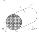
- FIG. 1 is a perspective view of an exhaust gas purification filter in Embodiment 1.
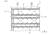
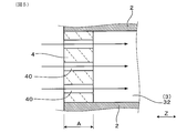
- FIG. 2 is a cross-sectional view parallel to the axial direction of the exhaust gas purification filter in Embodiment 1
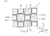
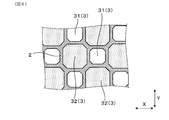
- FIG. 3 is an enlarged view of the exhaust gas purification filter according to the first embodiment when viewed from the axial direction.
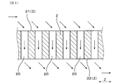
- FIG. 4 is a schematic cross-sectional view for explaining the pores of the cell wall in the first embodiment.
- FIG. 5 is a schematic cross-sectional view for explaining the pores of the plug portion in Embodiment 1.
- FIG. 6 is a diagram showing a modification of the first embodiment, and is an enlarged view of the exhaust gas purification filter viewed from the axial direction
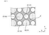
- FIG. 7 is a diagram showing another modification of the first embodiment, and is an enlarged view of the exhaust gas purification filter as viewed from the axial direction
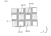
- FIG. 8 is a diagram showing still another modification of the first embodiment, and is an enlarged view of the exhaust gas purification filter viewed from the axial direction
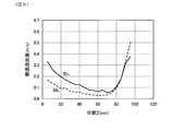
- FIG. 9 is a diagram showing the relationship between the position and the wall permeation flow velocity in Experimental Example 1
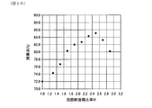
- FIG. 10 is a diagram showing the relationship between the flow path cross-sectional area ratio R and the collection rate in Experimental Example 2.
- FIG. 11 is a view of the exhaust gas purification filter in the second embodiment as seen from the axial direction.
- FIG. 11 is a view of the exhaust gas purification filter in the second embodiment as seen from the axial direction.
- FIG. 12 is an enlarged view of the periphery of the boundary line in FIG.
- FIG. 13 is a view showing a modification of the second embodiment, and is a view of the exhaust gas purification filter viewed from the axial direction.
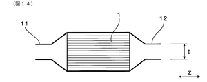
- FIG. 14 is a diagram illustrating a modification of the second embodiment, and is a schematic diagram illustrating a state where an exhaust gas purification filter is attached to a pipe.
- the exhaust gas purification filter 1 of this embodiment collects particulate matter in exhaust gas. As shown in FIGS. 1 and 2, the exhaust gas purification filter 1 has a plurality of cell walls 2 and a plurality of cell holes 3 surrounded by the plurality of cell walls 2.
- the exhaust gas purification filter 1 includes, as cell holes 3, downstream plugged cell holes 31 whose downstream ends are closed by plug portions 4 and opened upstream, and upstream ends are plug portions. And an upstream plugging cell hole 32 which is closed by 4 and opened on the downstream side.
- the flow path cross-sectional area of one downstream plugging cell hole 31 is S1
- the flow path cross-sectional area of one upstream plugging cell hole 32 is S2.
- the channel cross-sectional area ratio R S2 / S1, which is the ratio of the channel cross-sectional area S2 to the channel cross-sectional area S1, satisfies 1.7 ⁇ R ⁇ 3.0.
- the flow passage cross-sectional area S1 of one downstream plugging cell hole 31 is the one downstream plugging cell hole orthogonal to the axial direction Z of the exhaust gas purification filter 1.
- 31 is the area of the cross section 311 of 31.
- the flow passage cross-sectional area of one upstream plugging cell hole 32 is the area of the cross section 321 of the upstream plugging cell hole 32 perpendicular to the axial direction Z of the exhaust gas purification filter 1.
- the exhaust gas purification filter 1 can be used for purification of exhaust gas generated in an internal combustion engine of a car, for example, a diesel engine or a gasoline engine.
- the exhaust gas purification filter 1 is used by being attached to an exhaust pipe of an internal combustion engine.
- the axial direction of the exhaust gas purification filter 1 is simply referred to as the axial direction Z.
- the side where the exhaust gas is introduced of the exhaust gas purification filter 1 attached to the internal combustion engine is referred to as the upstream side, and the side where the exhaust gas is discharged is referred to as the downstream side. 2, 4, 5, and the like indicate the main exhaust gas flow when the exhaust gas purification filter 1 is used.
- the exhaust gas purification filter 1 has a cylindrical shape.
- the exhaust gas purification filter 1 includes an outer peripheral portion 5 formed in a cylindrical shape, cell walls 2 arranged in a lattice shape on the inner peripheral side of the outer peripheral portion 5, and a plurality of cell holes 3.
- the cell hole 3 facing the outer peripheral portion 5 is variously changed in shape and flow path cross-sectional area from the other cell holes 3. Therefore, in this specification, unless otherwise specified, the cell hole 3 means a cell hole other than the cell hole facing the outer peripheral portion 5.
- the cell hole 3 has a downstream plugging cell hole 31 and an upstream plugging cell hole 32.
- the downstream plugging cell hole 31 and the upstream plugging cell hole 32 are both in the axial direction Z and the horizontal direction X even in one direction orthogonal to the axial direction Z (hereinafter referred to as the horizontal direction X). Also in one direction orthogonal to (hereinafter, referred to as the longitudinal direction Y), they are alternately arranged so as to be adjacent to each other.
- the downstream plugging cell hole 31 and the upstream plugging cell hole 32 are arranged in a check pattern.
- the upstream plugging cell holes 32 are arranged to be adjacent to each other in the oblique directions XY1 and XY2 that are orthogonal to the axial direction Z and inclined by 45 ° with respect to both the horizontal direction X and the vertical direction Y. It is out.
- the thickness dimension of the portion 21 between the upstream plugging cell holes 32 adjacent to each other in the oblique directions XY1 and XY2 in the cell wall 2 is the same as the downstream plugging cell hole 31 adjacent to the horizontal direction X or the vertical direction Y in the cell wall 2 and the upstream plug. It is larger than the thickness dimension of the part 22 between the filling cell holes 32.
- the plurality of cell holes 3 have two or more types of shapes. That is, two or more types of cell holes 3 having different shapes when viewed from the axial direction Z are present in the plurality of cell holes 3.
- the cell hole 3 is composed of an octagonal cell hole 3 with an inner peripheral shape and a cell hole 3 with an inner peripheral shape of a quadrangle.
- a cell hole 3 having an octagonal inner periphery is an upstream plugging cell hole 32, and a cell hole 3 having an inner peripheral shape is a square is a downstream plugging cell hole 31.
- the upstream plugging cell hole 32 has an octagonal shape with a 1/4 rotation symmetry
- the downstream plugging cell hole 31 has a square shape.
- the shape of each cell hole 3 may be a shape in which some curves or tapers are formed at the corners.
- the quadrangular shape (square shape) and the octagonal shape are concepts including such a shape.
- the channel cross-sectional area ratio R which is the ratio of the channel cross-sectional area S2 of the upstream plugging cell hole 32 to the channel cross-sectional area S1 of the downstream plugging cell hole 31, is 1.7 ⁇ R ⁇ 3.0. Meet.
- the channel cross-sectional area ratio R is, for example, the average of the channel cross-sectional areas of the five randomly selected downstream plugging cell holes 31 and the channel of the five randomly selected upstream plugging cell holes 32. It can be calculated from the average value of the cross-sectional areas. Further, the flow path cross-sectional area ratio R is not limited to this.
- the flow path cross-sectional area ratio R is determined from the flow path cross-sectional areas in the downstream plugging cell hole 31 and the upstream plugging cell hole 32 adjacent to each other in the horizontal direction X or the vertical direction Y It may be calculated.
- the channel cross-sectional area ratio R further satisfies R ⁇ 2.5. That is, in the present embodiment, the flow path cross-sectional area ratio R satisfies 1.7 ⁇ R ⁇ 2.5.
- the flow path cross-sectional area S1 of the downstream plugged cell hole 31 satisfies 0.5 mm 2 ⁇ S1 ⁇ 3.0 mm 2 .
- the total sum Sa of the channel cross-sectional areas of all the downstream plugging cell holes 31 satisfies 7 cm 2 ⁇ Sa ⁇ 100 cm 2 .
- the exhaust gas purification filter 1 has a constant cell pitch cp both in the vertical direction Y and in the horizontal direction X.
- the cell pitch cp is calculated by (length of downstream plugged cell hole 31/2) + (thickness of cell wall 2) + (length of upstream plugged cell hole 32).
- the cell pitch cp is 1.505 mm.
- the cell wall 2 has a thickness of 0.24 mm.
- the average pore diameter of the cell wall 2 is 15 ⁇ m.
- the porosity of the cell wall 2 is 63%.
- the plug portion 4 is composed mainly of cordierite having a SiO 2 content of 45 to 55 wt%, an Al 2 O 3 content of 33 to 42 wt%, and an MgO content of 12 to 18 wt%.
- the plug portion 4 is arranged so as to close the end portion of the cell hole 3 in the axial direction Z.
- the plug portion 4 is formed with pores 40 communicating from the upstream end to the downstream end.
- the schematic diagram of the pore of the plug part 4 is represented.
- the plug portion 4 has a porosity of 50% to 70%.
- the length A of the plug portion 4 that closes the upstream plugged cell hole 32 in the axial direction Z and the flow path cross-sectional area ratio R have a relationship of 1.0 mm ⁇ A ⁇ (6.0 / R) mm. Fulfill.
- the relationship between the length AA of the plug portion 4 that closes the downstream plugged cell hole 32 and the flow path cross-sectional area ratio R is also 1.0 mm ⁇ AA ⁇ (6.0 / R) mm.
- the cell wall 2 is made of a ceramic material having a porous structure.
- the cell wall 2 has cordierite having a SiO 2 content of 45 to 55 wt%, an Al 2 O 3 content of 33 to 42 wt%, and an MgO content of 12 to 18 wt%. Is the main component.
- the cell wall 2 can be comprised from the material which mixed at least 3 types of the raw material of a kaolin, a silica, porous silica, a talc, aluminum hydroxide, and an alumina at least.
- the cell wall 2 and the plug part 4 can be obtained by adding water, lubricating oil, a binder, etc.
- a plurality of pores 20 that communicate between adjacent cell holes 3 are formed inside the cell wall 2.
- the schematic diagram of the pore 20 is shown.
- many of the plurality of pores 20 have the same inner diameter.
- the total length L of the exhaust gas purification filter 1 in the axial direction Z satisfies 50 mm ⁇ L ⁇ 200 mm. In the present embodiment, the total length L of the exhaust gas purification filter 1 is 100 mm. Moreover, the diameter D of the exhaust gas purification filter 1 satisfies 80 mm ⁇ D ⁇ 200 mm. In this embodiment, the diameter D of the exhaust gas purification filter 1 is 129 mm.
- the flow path cross-sectional area ratio R S2 / S1 satisfies 1.7 ⁇ R ⁇ 3.0. Therefore, the flow rate of the exhaust gas passing through the cell wall 2 can be equalized in the axial direction Z of the exhaust gas purification filter 1. Thereby, permeation
- transmission of exhaust gas can be suppressed to a part of cell wall 2 in the axial direction Z of the exhaust gas purification filter 1. Therefore, in the exhaust gas purification filter 1, the cell wall 2 can be effectively used from the viewpoint of collecting particulate matter, and the filtration area can be increased as a whole. As a result, the collection rate of particulate matter can be improved.
- the collection rate of the particulate matter in the exhaust gas purification filter 1 may be simply referred to as “collection rate”.
- the channel cross-sectional area ratio R further satisfies R ⁇ 2.5. Therefore, the value of the flow path cross-sectional area ratio R has changed due to the dimensional error of the cell wall 2 when the exhaust gas purification filter 1 is formed by die processing, the shrinkage of the exhaust gas purification filter 1 generated during drying and firing, and the like. Sometimes, the collection rate can be prevented from greatly fluctuating. Thereby, the required dimensional tolerance of the cell wall 2 can be easily increased, and the exhaust gas purification filter 1 can be easily manufactured.
- the length A of the plug portion 4 that closes the upstream plugged cell hole 32 in the axial direction Z and the flow path cross-sectional area ratio R have a relationship of 1.0 mm ⁇ A ⁇ (6.0 / R) mm. Fulfill.
- the connectivity between the cell wall 2 and the plug part 4 is increased, and the strength of the exhaust gas purification filter 1 can be improved.
- the length A of the plug portion 4 is less than 1.0 mm, the connectivity between the cell wall 2 and the plug portion 4 tends to deteriorate, and the strength of the exhaust gas purification filter 1 tends to decrease accordingly.
- the length A of the plug portion 4 is set to (6.0 / R) mm or less, it is easy to ensure the collection rate even when the value of the channel cross-sectional area ratio R is relatively large. That is, when the value of the flow path cross-sectional area ratio R is relatively large, the exhaust gas tends to permeate the cell wall 2 in a concentrated manner on the upstream side of the cell wall 2. Therefore, when the flow path cross-sectional area ratio R is relatively large, the length A of the plug portion 4 is shortened to allow the exhaust gas to permeate the plug portion 4 and trap particulate matter in the plug portion 4. Can be collected. As a result, it is easy to ensure the collection rate even when the value of the channel cross-sectional area ratio R is relatively large.
- the exhaust gas is difficult to permeate the plug portion 4, so that the collection is performed when the value of the channel cross-sectional area ratio R is relatively large. It is difficult to secure the rate.
- an exhaust gas purification filter that can improve the collection rate of particulate matter by effectively utilizing the cell wall from the viewpoint of particulate matter collection.
- the shape of the downstream plugging cell hole 31 and the upstream plugging cell hole 32 is not necessarily limited to a combination of a square shape and an octagonal shape.
- the shapes of the downstream plugging cell holes 31 and the upstream plugging cell holes 32 may be octagonal shapes.
- the shapes of the downstream plugging cell hole 31 and the upstream plugging cell hole 32 may be circular.
- the downstream plugged cell hole 31 and the upstream plugged cell hole 32 may both be square, but in this case, the cell wall 2 on the diagonal line of the upstream plugged cell hole 32.
- the strength tends to decrease.
- the shape of the downstream plugging cell hole 31 and the upstream plugging cell hole 32 is a combination of a square shape and an octagonal shape as shown in FIG. 3, or as shown in FIG. An octagonal shape is preferred.
- the square shape shown in FIG. 3 is compared to the configuration shown in FIG. 7 where the downstream plugging cell hole 31 and the upstream plugging cell hole 32 are both circular. It is preferable to use a combination of a shape and an octagon shape, or a combination of octagon shapes as shown in FIG.
- Example 1 the flow rate of the exhaust gas that permeates the cell wall 2 is analyzed for each position in the axial direction Z on the cell wall 2.
- the flow rate of the exhaust gas that permeates the cell wall 2 in the exhaust gas purification filter may be referred to as a wall permeation flow rate.
- two exhaust gas purification filters having the same basic structure as that of the first embodiment but having different flow path cross-sectional area ratios R are assumed. Specifically, a sample 1 with a channel cross-sectional area ratio R of 1 and a sample 2 with a channel cross-sectional area ratio R of 1.7 were assumed. That is, the sample 2 is the exhaust gas purification filter 1 in which the flow path cross-sectional area ratio R satisfies 1.7 ⁇ R ⁇ 3.0.
- FIG. 9 The results are shown in FIG. 9, the result of the sample 1 is represented by a broken line BL, and the result of the sample 2 is represented by a solid line SL. Further, the position z shown on the horizontal axis in FIG. 9 indicates the length in the axial direction Z from the upstream end of each sample.
- the sample 1 with the flow path cross-sectional area ratio R of 1 has a wall permeation flow velocity in the downstream end region where the position z is around 80 to 100 mm compared to the region upstream of the downstream end region. It can be seen that it is much larger. That is, it can be seen that the sample 1 is concentrated in the downstream end region of the exhaust gas purification filter in the axial direction Z and the exhaust gas is transmitted through the cell wall.
- Sample 2 with a flow path cross-sectional area ratio R of 1.7 has a reduced wall permeation flow velocity in the downstream end region compared to Sample 1, and accordingly, more upstream than the downstream end region.
- the wall permeation flow velocity can be secured in the region of.
- the sample 2 can equalize the wall permeation
- the exhaust gas flows straight along the axial direction Z from the upstream end of the downstream plugging cell hole 31.
- Example 2 This example is an example of examining the influence on the collection rate when the flow path cross-sectional area ratio R is changed in the exhaust gas purification filter.
- each sample had an overall length L in the axial direction Z of 100 m, a diameter D of 129 mm, a cell pitch cp of 1.505 mm, a thickness of the cell wall 2 of 0.24 mm, an average pore diameter of 15 ⁇ m, and a porosity of 63%.
- each sample was attached to an exhaust pipe of an engine, and exhaust gas was circulated through each sample at a temperature of 450 ° C. and a flow rate of 2.76 m 3 / min.
- the collection rate In calculating the collection rate, the number of particulate matter contained in the exhaust gas introduced into each sample and the number of particulate matter contained in the exhaust gas discharged from each sample were measured. And the collection rate was obtained by calculating the ratio of the number of the particulate matter contained in the exhaust gas discharged from each sample to the number of the particulate matter contained in the exhaust gas introduced into each sample. The results are shown in FIG.
- a sample satisfying a flow path cross-sectional area ratio R of 1.7 ⁇ R ⁇ 3.0 has a higher collection rate than a sample having another flow path cross-sectional area ratio R.
- the flow path cross-sectional area ratio R is less than 1.7, it can be seen that the collection rate rapidly decreases. Therefore, it can be seen that the flow path cross-sectional area ratio R preferably satisfies 1.7 ⁇ R ⁇ 3.0 from the viewpoint of securing the collection rate.
- the present embodiment is an embodiment in which the cell wall 2 carries a catalyst.
- the plug portion 4 also carries a catalyst. By supporting the catalyst on the cell wall 2 and the plug portion 4, harmful substances contained in the exhaust gas can be removed.
- the catalyst is a three-way catalyst containing at least one of Pt, Rh, and Pd.
- the exhaust gas purification filter 1 of the present embodiment is the same as the exhaust gas purification filter shown in the first embodiment, with a catalyst supported thereon.
- the exhaust gas purification filter 1 of this example includes the surface of the cell wall 2 facing the downstream plugging cell hole 31 and the upstream plugging cell hole 32 in Embodiment 1, and the surface of the pore 20 of the cell wall 2.
- the surface of the plug part 4 and the surface of the pore 40 of the plug part 4 are coated with a catalyst. Note that the reference numerals described in the present embodiment indicate the correspondence with FIGS. 1 to 5 of the first embodiment.
- the present embodiment has a center side region 6 including the central axis of the exhaust gas purification filter 1 and an outer peripheral side region 7 disposed on the outer peripheral side of the central side region 6.
- the shape of the downstream plugged cell hole 31 is changed between the central region 6 and the outer peripheral region 7.
- the flow passage cross-sectional area of the downstream plugging cell hole 31 in the outer peripheral region 7 is made larger than the flow passage cross-sectional area of the downstream plugging cell hole 31 in the central region 6. Yes.
- the exhaust gas purification filter 1 has a constant cell pitch over the central region 6 and the outer peripheral region 7. Therefore, the difference in the flow path cross-sectional area of the downstream plugged cell hole 31 between the center side region 6 and the outer peripheral side region 7 is constituted by the difference in the thickness of the cell wall 2. That is, the cell wall 2 is formed so that the outer peripheral side region 7 is thinner than the central side region 6.
- S1o is a flow path cross-sectional area of one downstream plugged cell hole 31 in the outer peripheral side region 7. That is, as shown in FIG. 12, the area of the cross section 311o orthogonal to the axial direction Z in one downstream plugged cell hole 31 in the outer peripheral side region 7 is S1o. And let the flow-path cross-sectional area of the one upstream plugging cell hole 32 in the outer peripheral side area
- region 7 be S2. That is, the area of the cross section 321o orthogonal to the axial direction Z in one upstream plugging cell hole 32 in the outer peripheral side region 7 is S2o.
- the flow path cross-sectional area of one downstream plugged cell hole 31 in the central region 6 is defined as S1c. That is, the area of the cross section 311c orthogonal to the axial direction Z in one downstream plugged cell hole 31 in the center side region 6 is S1c. And let the flow-path cross-sectional area of the one upstream plugging cell hole 32 in the center side area
- region 6 be S2. That is, the area of the cross section 321c orthogonal to the axial direction Z in one upstream plugging cell hole 32 in the central region 6 is S2c.
- the channel cross-sectional area ratio Ro in the outer peripheral side region 7 is smaller than the channel cross-sectional area ratio Rc in the central side region.
- the flow path cross-sectional area ratio Rc in the center side region 6 and the flow path cross-sectional area ratio Ro in the outer peripheral side region 7 are in the range of 1.7 to 3.0, respectively.
- the channel cross-sectional area S2o is larger than the channel cross-sectional area S1c.
- the present invention is not limited to this, and if each of the above-described channel cross-sectional area ratios Rc and Ro is within the range of 1.7 to 3.0, the channel cross-sectional area S2o is the channel cross-sectional area. It is possible to adopt a configuration smaller than S1c or the same configuration as the flow path cross-sectional area S1c.
- the boundary line B between the central region 6 and the outer peripheral region 7 has an octagonal shape.
- the boundary line B is formed in an octagonal shape that is a 1/4 rotation target.
- the boundary line B is shown as a line drawn so as to connect a plurality of downstream plugged cell holes 31 arranged at the inner peripheral end in the outer peripheral side region 7. It may be a line drawn so as to connect a plurality of downstream plugging cell holes 31 or upstream plugging cell holes 32 arranged at the outer peripheral edge in the side region 6. This is because all of them are similar in shape, and the shape is the same regardless of which boundary line B is selected. Others are the same as in the first embodiment.
- the exhaust gas flow rate is possible to prevent the exhaust gas flow rate from being biased in the radial direction of the exhaust gas purification filter 1. That is, generally, when exhaust gas is introduced along the axial direction Z with respect to the exhaust gas purification filter 1 disposed in the exhaust gas flow path, the flow velocity near the central axis tends to increase. Therefore, in the present embodiment, the flow passage cross-sectional area of the downstream plugging cell hole 31 in the outer peripheral side region 7 where the exhaust gas does not easily flow is made larger than the flow passage cross-sectional area of the downstream plugging cell hole 31 in the central region. Yes. Thereby, compared with the exhaust gas purification filter 1 having a uniform cell structure, the exhaust gas can easily flow to the outer peripheral region 7.
- the cell wall 2 can be effectively used in both the outer peripheral side region 7 and the central side region, and the filtration area can be increased as a whole. As a result, it is easy to improve the collection rate of the particulate matter. In addition, the same effects as those of the first embodiment are obtained.
- the shape of the boundary line B is not limited to an octagonal shape, and may be a rectangular shape as shown in FIG. 13, for example.
- the boundary line B has a quadrangular shape, it is particularly preferable to have a square shape.
- the boundary line B has a quadrangular shape, particularly a square shape, the exhaust gas purification filter 1 can be easily manufactured. That is, when the die for forming the exhaust gas purification filter 1 is subjected to electric discharge machining, the shape of the electrode for electric discharge machining can be unified into a quadrangle. As a result, manufacture of the exhaust gas purification filter 1 can be facilitated.
- the boundary line B has an octagonal shape
- the distance between the boundary line B and the outer peripheral portion 5 is less likely to vary depending on the position in the circumferential direction. As a result, it is easy to increase the load resistance when the exhaust gas purification filter 1 is installed in the pipe.
- the boundary line B is preferably sized and shaped so that its inscribed circle is equal to or larger than the inner diameter of the upstream and downstream piping of the exhaust gas purification filter 1. That is, the exhaust gas purification filter 1 is disposed in the pipes 11 and 12 as shown in FIG. Pipes 11 and 12 having an inner diameter I smaller than the outer diameter of the exhaust gas purification filter 1 are connected to the upstream side and the downstream side of the portion where the exhaust gas purification filter 1 is disposed.
- the diameter of the inscribed circle of the boundary line B is preferably set to be equal to or larger than the inner diameter I of the pipes 11 and 12 on the upstream side and the downstream side of the exhaust gas purification filter 1. In particular, when viewed from the axial direction Z, it is preferable that the inner peripheral contours of the pipes 11 and 12 be inside the boundary line B.
- the diameter of the inscribed circle of the boundary line B is preferably 3/4 or less of the diameter of the exhaust gas purification filter 1.
- boundary line B is not necessarily formed in a point-symmetric shape and position around the central axis of the exhaust gas purification filter 1.
- the position and shape of the boundary line B can be appropriately changed according to the relationship between the exhaust gas purification filter 1 and the relative positions of the upstream and downstream pipes 11 and 12.
Abstract
Provided is an exhaust gas purification filter that can improve particulate matter collection rate by effectively using cell walls from the viewpoint of particulate matter collection. An exhaust gas purification filter (1) is for collecting particulate matter in exhaust gas. The exhaust gas purification filter (1) has a plurality of cell walls (2) and a plurality of cell holes (3) surrounded by the plurality of cell walls (2). For cell holes (3), the exhaust gas purification filter (1) has downstream plugged cell holes (31) wherein the downstream side end is closed by a plug part and the upstream side is open and upstream plugged cell holes (32) wherein the upstream side end is closed by a plug part and the downstream side is open. Letting S1 be the flow path cross-sectional surface area for a downstream plugged cell hole (31) in one location and let S2 the flow path cross-sectional surface area for an upstream plugged cell hole (32) at one location, flow path cross-sectional surface area proportion R = S2/S1, which is the proportion of flow path cross-sectional surface area S2 to flow path cross-sectional surface area S1, satisfies 1.7 ≤ R ≤ 3.0.
Description
本出願は、2016年9月5日に出願された日本出願番号2016-172963号に基づくもので、ここにその内容を援用する。
This application is based on Japanese Application No. 2016-172963 filed on September 5, 2016, the contents of which are incorporated herein by reference.
本開示は、内燃機関の排ガスを浄化するための排ガス浄化フィルタに関する。
The present disclosure relates to an exhaust gas purification filter for purifying exhaust gas of an internal combustion engine.
内燃機関の排気管には、排ガスに含まれる粒子状物質(Particulate Matter:PM)を捕集する排ガス浄化装置が設けられている。この排ガス浄化装置には、特許文献1に示されているように、排ガスに含まれる粒子状物質を捕集するための排ガス浄化フィルタを備えたものがある。
The exhaust pipe of the internal combustion engine is provided with an exhaust gas purification device that collects particulate matter (PM) contained in the exhaust gas. Some of the exhaust gas purifying apparatuses include an exhaust gas purifying filter for collecting particulate matter contained in the exhaust gas as disclosed in Patent Document 1.
特許文献1に記載された排ガス浄化フィルタは、複数のセル壁と、セル壁によって囲まれて形成されたセル孔とを有している。複数のセル孔のうちの一部は、上流側の端面が栓部によって閉塞された上流栓詰めセル孔であり、他の一部は、下流側の端面が栓部によって閉塞された下流栓詰めセル孔である。そして、特許文献1に記載された排ガス浄化フィルタは、下流栓詰めセル孔から排ガスを流入し、流入した排ガスをセル壁に確実に透過させ、上流側栓詰めセルから排出するように構成されている。排ガス浄化フィルタは、セル壁に排ガスを透過させることにより、排ガス中の粒子状物質をセル壁に捕集する。これにより、排ガス浄化フィルタは、排ガスから粒子状物質を除去している。
The exhaust gas purification filter described in Patent Document 1 has a plurality of cell walls and cell holes formed surrounded by the cell walls. Some of the plurality of cell holes are upstream plugging cell holes whose upstream end faces are blocked by plug parts, and the other part are downstream plugging whose downstream end faces are blocked by plug parts. It is a cell hole. The exhaust gas purification filter described in Patent Document 1 is configured to allow exhaust gas to flow in from the downstream plugging cell hole, to reliably permeate the exhaust gas that has flowed into the cell wall, and to discharge from the upstream plugging cell. Yes. The exhaust gas purification filter collects particulate matter in the exhaust gas on the cell wall by allowing the exhaust gas to permeate the cell wall. Thereby, the exhaust gas purification filter removes particulate matter from the exhaust gas.
しかしながら、排ガス浄化フィルタに排ガスを通すことにより、排ガスの圧損が上昇することが懸念される。そこで、特許文献1に記載の排ガス浄化フィルタは、排ガスの圧損を低減すべく、上流栓詰めセル孔の流路断面積を、下流栓詰めセル孔の流路断面積よりも大きく形成している。
However, there is a concern that the pressure loss of the exhaust gas increases by passing the exhaust gas through the exhaust gas purification filter. Therefore, in the exhaust gas purification filter described in Patent Document 1, the flow passage cross-sectional area of the upstream plugging cell hole is formed larger than the flow passage cross-sectional area of the downstream plugging cell hole in order to reduce the pressure loss of the exhaust gas. .
特許文献1に記載の排ガス浄化フィルタにおいては、下流栓詰めセル孔の流路断面積に対する上流栓詰めセル孔の流路断面積の比率が充分ではない。そのため、上記排ガス浄化フィルタにおいては、粒子状物質の捕集の観点から、セル壁を有効活用できていない。
In the exhaust gas purification filter described in Patent Document 1, the ratio of the channel cross-sectional area of the upstream plugging cell hole to the channel cross-sectional area of the downstream plugging cell hole is not sufficient. For this reason, in the exhaust gas purification filter, the cell wall cannot be effectively utilized from the viewpoint of collecting particulate matter.
すなわち、特許文献1に記載の排ガス浄化フィルタは、排ガス浄化フィルタの上流側の領域においては、下流栓詰めセル孔と上流栓詰めセル孔との間に生じる差圧が大きくなり難いため、排ガスがセル壁を通過しにくい。一方、下流栓詰めセル孔に流入した排ガスは、下流栓詰めセル孔を閉塞する栓部によって下流栓詰めセル孔の下流側の領域に収容され、さらに下流栓詰めセル孔に流入される排ガスに押されて、セル壁の下流側の部位を透過する。そのため、特許文献1に記載の排ガス浄化フィルタにおいては、セル壁の下流側の部位に集中して排ガスが透過しており、セル壁における上流側の部位及び中央部位においては、粒子状物質捕集の観点から有効活用できていない。それゆえ、特許文献1に記載の排ガス浄化フィルタにおいては、粒子状物質の捕集率を向上しにくい。
That is, in the exhaust gas purification filter described in Patent Document 1, in the region upstream of the exhaust gas purification filter, the differential pressure generated between the downstream plugging cell hole and the upstream plugging cell hole is difficult to increase, Difficult to pass through cell walls. On the other hand, the exhaust gas flowing into the downstream plugging cell hole is accommodated in a region downstream of the downstream plugging cell hole by the plug portion closing the downstream plugging cell hole, and further into the exhaust gas flowing into the downstream plugging cell hole. It is pushed and permeates the downstream part of the cell wall. For this reason, in the exhaust gas purification filter described in Patent Document 1, exhaust gas is concentrated in the downstream portion of the cell wall, and particulate matter is collected in the upstream portion and the central portion of the cell wall. It cannot be effectively used from the viewpoint of. Therefore, in the exhaust gas purification filter described in Patent Document 1, it is difficult to improve the collection rate of particulate matter.
本開示は、粒子状物質捕集の観点からセル壁を有効活用することにより、粒子状物質の捕集率を向上することができる排ガス浄化フィルタを提供しようとするものである。
This disclosure intends to provide an exhaust gas purification filter capable of improving the collection rate of particulate matter by effectively utilizing the cell wall from the viewpoint of particulate matter collection.
本開示の第一の態様は、排ガス中の粒子状物質を捕集するための排ガス浄化フィルタであって、
複数のセル壁と、複数の該セル壁によって囲まれた複数のセル孔と、を有し、
上記セル孔として、下流側端部が栓部によって閉塞されるとともに上流側が開放された下流栓詰めセル孔と、上流側端部が栓部によって閉塞されるとともに下流側が開放された上流栓詰めセル孔と、を有し、
1箇所の上記下流栓詰めセル孔の流路断面積をS1、1箇所の上記上流栓詰めセル孔の流路断面積をS2としたとき、流路断面積S1に対する流路断面積S2の比率である流路断面積比率R=S2/S1は、1.7≦R≦3.0を満たす、排ガス浄化フィルタにある。 A first aspect of the present disclosure is an exhaust gas purification filter for collecting particulate matter in exhaust gas,
A plurality of cell walls, and a plurality of cell holes surrounded by the plurality of cell walls,
As the cell hole, a downstream plugging cell hole whose downstream end is closed by a plug part and whose upstream side is opened, and an upstream plugging cell whose upstream end part is closed by a plug part and whose downstream side is opened A hole, and
The ratio of the channel cross-sectional area S2 to the channel cross-sectional area S1 when the channel cross-sectional area of one downstream plugging cell hole is S1, and the channel cross-sectional area of the one upstream plugging cell hole is S2. The flow path cross-sectional area ratio R = S2 / S1 is in the exhaust gas purification filter satisfying 1.7 ≦ R ≦ 3.0.
上記排ガス浄化フィルタは、流路断面積比率R=S2/S1が、1.7≦R≦3.0を満たす。それゆえ、セル壁を通過する排ガスの流速を、排ガス浄化フィルタの軸方向において均等化することができる。これにより、排ガス浄化フィルタの軸方向におけるセル壁の一部に排ガスの透過が集中することを抑制することができる。それゆえ、上記排ガス浄化フィルタにおいては、粒子状物質の捕集の観点からセル壁を有効活用でき、全体として濾過面積を大きくできる。その結果、粒子状物質の捕集率を向上させることができる。なお、上記の数値に関しては、後述する実験例によって裏付けられる。
In the exhaust gas purification filter, the flow path cross-sectional area ratio R = S2 / S1 satisfies 1.7 ≦ R ≦ 3.0. Therefore, the flow velocity of the exhaust gas passing through the cell wall can be equalized in the axial direction of the exhaust gas purification filter. Thereby, it can suppress that permeation | transmission of exhaust gas concentrates on a part of cell wall in the axial direction of an exhaust gas purification filter. Therefore, in the exhaust gas purification filter, the cell wall can be effectively used from the viewpoint of collecting particulate matter, and the filtration area can be increased as a whole. As a result, the collection rate of particulate matter can be improved. In addition, about said numerical value, it is supported by the experimental example mentioned later.
以上のごとく、上記態様によれば、粒子状物質捕集の観点からセル壁を有効活用することにより、粒子状物質の捕集率を向上することができる排ガス浄化フィルタを提供することができる。
As described above, according to the above aspect, it is possible to provide an exhaust gas purification filter capable of improving the collection rate of particulate matter by effectively utilizing the cell wall from the viewpoint of particulate matter collection.
本開示についての上記目的及びその他の目的、特徴や利点は、添付の図面を参照しながら下記の詳細な記述により、より明確になる。その図面は、
図1は、実施形態1における、排ガス浄化フィルタの斜視図であり、
図2は、実施形態1における、排ガス浄化フィルタの軸方向に平行な断面図であり、
図3は、実施形態1における、排ガス浄化フィルタを軸方向からみた拡大図であり、
図4は、実施形態1における、セル壁の細孔を説明するための模式断面図であり、
図5は、実施形態1における、栓部の細孔を説明するための模式断面図であり、
図6は、実施形態1の変形形態を示す図であって、排ガス浄化フィルタを軸方向からみた拡大図であり、
図7は、実施形態1の他の変形形態を示す図であって、排ガス浄化フィルタを軸方向からみた拡大図であり、
図8は、実施形態1のさらに他の変形形態を示す図であって、排ガス浄化フィルタを軸方向からみた拡大図であり、
図9は、実験例1における、位置と壁透過流速との関係を示した線図であり、
図10は、実験例2における、流路断面積比率Rと捕集率との関係を示した線図であり、
図11は、実施形態2における、排ガス浄化フィルタを軸方向から見た図であり、
図12は、図11の、境界ラインの周辺を拡大した図であり、
図13は、実施形態2の変形形態を示す図であって、排ガス浄化フィルタを軸方向から見た図であり、
図14は、実施形態2の変形形態を示す図であって、排ガス浄化フィルタを配管に取り付けた様子を示す模式図である。
The above and other objects, features, and advantages of the present disclosure will become more apparent from the following detailed description with reference to the accompanying drawings. The drawing
FIG. 1 is a perspective view of an exhaust gas purification filter in Embodiment 1. FIG. 2 is a cross-sectional view parallel to the axial direction of the exhaust gas purification filter in Embodiment 1, FIG. 3 is an enlarged view of the exhaust gas purification filter according to the first embodiment when viewed from the axial direction. FIG. 4 is a schematic cross-sectional view for explaining the pores of the cell wall in the first embodiment. FIG. 5 is a schematic cross-sectional view for explaining the pores of the plug portion in Embodiment 1. FIG. 6 is a diagram showing a modification of the first embodiment, and is an enlarged view of the exhaust gas purification filter viewed from the axial direction; FIG. 7 is a diagram showing another modification of the first embodiment, and is an enlarged view of the exhaust gas purification filter as viewed from the axial direction; FIG. 8 is a diagram showing still another modification of the first embodiment, and is an enlarged view of the exhaust gas purification filter viewed from the axial direction; FIG. 9 is a diagram showing the relationship between the position and the wall permeation flow velocity in Experimental Example 1, FIG. 10 is a diagram showing the relationship between the flow path cross-sectional area ratio R and the collection rate in Experimental Example 2. FIG. 11 is a view of the exhaust gas purification filter in the second embodiment as seen from the axial direction. FIG. 12 is an enlarged view of the periphery of the boundary line in FIG. FIG. 13 is a view showing a modification of the second embodiment, and is a view of the exhaust gas purification filter viewed from the axial direction. FIG. 14 is a diagram illustrating a modification of the second embodiment, and is a schematic diagram illustrating a state where an exhaust gas purification filter is attached to a pipe.
(実施形態1)
排ガス浄化フィルタの実施形態につき、図1~図5を用いて説明する。
本実施形態の排ガス浄化フィルタ1は、排ガス中の粒子状物質を捕集するものである。図1、図2に示すごとく、排ガス浄化フィルタ1は、複数のセル壁2と複数のセル壁2によって囲まれた複数のセル孔3と、を有している。 (Embodiment 1)
An embodiment of an exhaust gas purification filter will be described with reference to FIGS.
The exhaustgas purification filter 1 of this embodiment collects particulate matter in exhaust gas. As shown in FIGS. 1 and 2, the exhaust gas purification filter 1 has a plurality of cell walls 2 and a plurality of cell holes 3 surrounded by the plurality of cell walls 2.
排ガス浄化フィルタの実施形態につき、図1~図5を用いて説明する。
本実施形態の排ガス浄化フィルタ1は、排ガス中の粒子状物質を捕集するものである。図1、図2に示すごとく、排ガス浄化フィルタ1は、複数のセル壁2と複数のセル壁2によって囲まれた複数のセル孔3と、を有している。 (Embodiment 1)
An embodiment of an exhaust gas purification filter will be described with reference to FIGS.
The exhaust
図2に示すごとく、排ガス浄化フィルタ1は、セル孔3として、下流側端部が栓部4によって閉塞されるとともに上流側が開放された下流栓詰めセル孔31と、上流側端部が栓部4によって閉塞されるとともに下流側が開放された上流栓詰めセル孔32と、を有する。1箇所の下流栓詰めセル孔31の流路断面積をS1とし、1箇所の上流栓詰めセル孔32の流路断面積をS2とする。このとき、流路断面積S1に対する流路断面積S2の比率である流路断面積比率R=S2/S1は、1.7≦R≦3.0を満たす。
なお、本実施形態において、図3に示すごとく、1箇所の下流栓詰めセル孔31の流路断面積S1は、排ガス浄化フィルタ1の軸方向Zに直交する当該1箇所の下流栓詰めセル孔31の断面311の面積である。また、1箇所の上流栓詰めセル孔32の流路断面積は、排ガス浄化フィルタ1の軸方向Zに直交する当該上流栓詰めセル孔32の断面321の面積である。 As shown in FIG. 2, the exhaustgas purification filter 1 includes, as cell holes 3, downstream plugged cell holes 31 whose downstream ends are closed by plug portions 4 and opened upstream, and upstream ends are plug portions. And an upstream plugging cell hole 32 which is closed by 4 and opened on the downstream side. The flow path cross-sectional area of one downstream plugging cell hole 31 is S1, and the flow path cross-sectional area of one upstream plugging cell hole 32 is S2. At this time, the channel cross-sectional area ratio R = S2 / S1, which is the ratio of the channel cross-sectional area S2 to the channel cross-sectional area S1, satisfies 1.7 ≦ R ≦ 3.0.
In the present embodiment, as shown in FIG. 3, the flow passage cross-sectional area S1 of one downstreamplugging cell hole 31 is the one downstream plugging cell hole orthogonal to the axial direction Z of the exhaust gas purification filter 1. 31 is the area of the cross section 311 of 31. The flow passage cross-sectional area of one upstream plugging cell hole 32 is the area of the cross section 321 of the upstream plugging cell hole 32 perpendicular to the axial direction Z of the exhaust gas purification filter 1.
なお、本実施形態において、図3に示すごとく、1箇所の下流栓詰めセル孔31の流路断面積S1は、排ガス浄化フィルタ1の軸方向Zに直交する当該1箇所の下流栓詰めセル孔31の断面311の面積である。また、1箇所の上流栓詰めセル孔32の流路断面積は、排ガス浄化フィルタ1の軸方向Zに直交する当該上流栓詰めセル孔32の断面321の面積である。 As shown in FIG. 2, the exhaust
In the present embodiment, as shown in FIG. 3, the flow passage cross-sectional area S1 of one downstream
排ガス浄化フィルタ1は、自動車の内燃機関、例えばディーゼルエンジンやガソリンエンジンにおいて発生した排ガスの浄化に用いることができる。排ガス浄化フィルタ1は、内燃機関の排気管に取り付けられて用いられる。以下、排ガス浄化フィルタ1の軸方向を、単に軸方向Zという。また、軸方向Zにおいて、内燃機関に取り付けられた排ガス浄化フィルタ1の、排ガスが導入される側を上流側といい、排ガスが排出される側を下流側という。なお、図2、図4、図5等において表した矢印は、排ガス浄化フィルタ1の使用時における、主要な排ガスの流れを表している。
The exhaust gas purification filter 1 can be used for purification of exhaust gas generated in an internal combustion engine of a car, for example, a diesel engine or a gasoline engine. The exhaust gas purification filter 1 is used by being attached to an exhaust pipe of an internal combustion engine. Hereinafter, the axial direction of the exhaust gas purification filter 1 is simply referred to as the axial direction Z. Further, in the axial direction Z, the side where the exhaust gas is introduced of the exhaust gas purification filter 1 attached to the internal combustion engine is referred to as the upstream side, and the side where the exhaust gas is discharged is referred to as the downstream side. 2, 4, 5, and the like indicate the main exhaust gas flow when the exhaust gas purification filter 1 is used.
図1に示すごとく、排ガス浄化フィルタ1は、円柱形状を呈している。排ガス浄化フィルタ1は、円筒形状に形成された外周部5と、外周部5の内周側において格子状に配設されたセル壁2と、複数のセル孔3とを有する。なお、複数のセル孔3のうち、外周部5に面するセル孔3は、他のセル孔3と形状、流路断面積が種々変更される。それゆえ、本明細書において、特に言及しない限り、セル孔3は、外周部5に面するセル孔以外のセル孔を意味する。
As shown in FIG. 1, the exhaust gas purification filter 1 has a cylindrical shape. The exhaust gas purification filter 1 includes an outer peripheral portion 5 formed in a cylindrical shape, cell walls 2 arranged in a lattice shape on the inner peripheral side of the outer peripheral portion 5, and a plurality of cell holes 3. Of the plurality of cell holes 3, the cell hole 3 facing the outer peripheral portion 5 is variously changed in shape and flow path cross-sectional area from the other cell holes 3. Therefore, in this specification, unless otherwise specified, the cell hole 3 means a cell hole other than the cell hole facing the outer peripheral portion 5.
図1、図3に示すごとく、セル孔3は、下流栓詰めセル孔31と上流栓詰めセル孔32とを有する。図3に示すごとく、下流栓詰めセル孔31と上流栓詰めセル孔32とは、軸方向Zに直交する一方向(以下、横方向Xという)においても、軸方向Z及び横方向Xの双方に直交する一方向(以下、縦方向Yという)においても、互いに隣り合うよう、交互に並んで形成されている。このように、下流栓詰めセル孔31と上流栓詰めセル孔32とは、軸方向Zから見たとき、チェック模様状に配されている。なお、上流栓詰めセル孔32同士は、軸方向Zに直交する方向であって、横方向X及び縦方向Yの双方に対して45°傾斜した斜め方向XY1、XY2において、互いに隣り合うよう並んでいる。セル壁2における斜め方向XY1、XY2に隣り合う上流栓詰めセル孔32間の部位21の厚み寸法は、セル壁2における横方向X又は縦方向Yに隣り合う下流栓詰めセル孔31と上流栓詰めセル孔32との間の部位22の厚み寸法よりも大きい。
As shown in FIGS. 1 and 3, the cell hole 3 has a downstream plugging cell hole 31 and an upstream plugging cell hole 32. As shown in FIG. 3, the downstream plugging cell hole 31 and the upstream plugging cell hole 32 are both in the axial direction Z and the horizontal direction X even in one direction orthogonal to the axial direction Z (hereinafter referred to as the horizontal direction X). Also in one direction orthogonal to (hereinafter, referred to as the longitudinal direction Y), they are alternately arranged so as to be adjacent to each other. Thus, when viewed from the axial direction Z, the downstream plugging cell hole 31 and the upstream plugging cell hole 32 are arranged in a check pattern. The upstream plugging cell holes 32 are arranged to be adjacent to each other in the oblique directions XY1 and XY2 that are orthogonal to the axial direction Z and inclined by 45 ° with respect to both the horizontal direction X and the vertical direction Y. It is out. The thickness dimension of the portion 21 between the upstream plugging cell holes 32 adjacent to each other in the oblique directions XY1 and XY2 in the cell wall 2 is the same as the downstream plugging cell hole 31 adjacent to the horizontal direction X or the vertical direction Y in the cell wall 2 and the upstream plug. It is larger than the thickness dimension of the part 22 between the filling cell holes 32.
本実施形態において、複数のセル孔3は、2種類以上の形状を有する。すなわち、複数のセル孔3の中に、軸方向Zから見たときの形状が互いに異なる2種以上のセル孔3が存在する。本実施形態において、セル孔3は、内周形状が八角形のセル孔3と、内周形状が四角形のセル孔3とからなる。内周形状が八角形のセル孔3が上流栓詰めセル孔32であり、内周形状が四角形のセル孔3が下流栓詰めセル孔31である。特に、本実施形態において、上流栓詰めセル孔32は1/4回転対称の八角形状であり、下流栓詰めセル孔31は正方形である。なお、実際の排ガス浄化フィルタ1において、各セル孔3の形状は、その角部において多少の曲線やテーパが形成された形状となることもある。上記の四角形状(正方形状)、八角形状とは、そのような形状も含む概念である。
In the present embodiment, the plurality of cell holes 3 have two or more types of shapes. That is, two or more types of cell holes 3 having different shapes when viewed from the axial direction Z are present in the plurality of cell holes 3. In the present embodiment, the cell hole 3 is composed of an octagonal cell hole 3 with an inner peripheral shape and a cell hole 3 with an inner peripheral shape of a quadrangle. A cell hole 3 having an octagonal inner periphery is an upstream plugging cell hole 32, and a cell hole 3 having an inner peripheral shape is a square is a downstream plugging cell hole 31. In particular, in the present embodiment, the upstream plugging cell hole 32 has an octagonal shape with a 1/4 rotation symmetry, and the downstream plugging cell hole 31 has a square shape. In the actual exhaust gas purification filter 1, the shape of each cell hole 3 may be a shape in which some curves or tapers are formed at the corners. The quadrangular shape (square shape) and the octagonal shape are concepts including such a shape.
上述のごとく、下流栓詰めセル孔31の流路断面積S1に対する上流栓詰めセル孔32の流路断面積S2の比率である流路断面積比率Rは、1.7≦R≦3.0を満たす。流路断面積比率Rは、例えば、無作為に選択した5箇所の下流栓詰めセル孔31の流路断面積の平均と、無作為に選択した5箇所の上流栓詰めセル孔32の流路断面積の平均値とから算出することができる。また、これに限られず、流路断面積比率Rは、例えば、横方向X又は縦方向Yにおいて互いに隣り合う下流栓詰めセル孔31及び上流栓詰めセル孔32における、それぞれの流路断面積から算出してもよい。本実施形態において、流路断面積比率Rは、R≦2.5を更に満たす。すなわち、本実施形態において、流路断面積比率Rは、1.7≦R≦2.5を満たす。
As described above, the channel cross-sectional area ratio R, which is the ratio of the channel cross-sectional area S2 of the upstream plugging cell hole 32 to the channel cross-sectional area S1 of the downstream plugging cell hole 31, is 1.7 ≦ R ≦ 3.0. Meet. The channel cross-sectional area ratio R is, for example, the average of the channel cross-sectional areas of the five randomly selected downstream plugging cell holes 31 and the channel of the five randomly selected upstream plugging cell holes 32. It can be calculated from the average value of the cross-sectional areas. Further, the flow path cross-sectional area ratio R is not limited to this. For example, the flow path cross-sectional area ratio R is determined from the flow path cross-sectional areas in the downstream plugging cell hole 31 and the upstream plugging cell hole 32 adjacent to each other in the horizontal direction X or the vertical direction Y It may be calculated. In the present embodiment, the channel cross-sectional area ratio R further satisfies R ≦ 2.5. That is, in the present embodiment, the flow path cross-sectional area ratio R satisfies 1.7 ≦ R ≦ 2.5.
本実施形態において、下流栓詰めセル孔31の流路断面積S1は、0.5mm2≦S1≦3.0mm2を満たす。また、すべての下流栓詰めセル孔31の流路断面積の総和Saは、7cm2≦Sa≦100cm2を満たす。
In the present embodiment, the flow path cross-sectional area S1 of the downstream plugged cell hole 31 satisfies 0.5 mm 2 ≦ S1 ≦ 3.0 mm 2 . In addition, the total sum Sa of the channel cross-sectional areas of all the downstream plugging cell holes 31 satisfies 7 cm 2 ≦ Sa ≦ 100 cm 2 .
また、図3に示すごとく、排ガス浄化フィルタ1は、縦方向Yにおいても、横方向Xにおいても、セルピッチcpが一定である。セルピッチcpは、(下流栓詰めセル孔31の長さ/2)+(セル壁2の厚み)+(上流栓詰めセル孔32の長さ/2)、で算出される。本実施形態において、セルピッチcpは、1.505mmである。また、セル壁2の厚みは、0.24mmである。さらに、セル壁2の平均気孔径は、15μmである。また、セル壁2の気孔率は、63%である。
Further, as shown in FIG. 3, the exhaust gas purification filter 1 has a constant cell pitch cp both in the vertical direction Y and in the horizontal direction X. The cell pitch cp is calculated by (length of downstream plugged cell hole 31/2) + (thickness of cell wall 2) + (length of upstream plugged cell hole 32). In the present embodiment, the cell pitch cp is 1.505 mm. The cell wall 2 has a thickness of 0.24 mm. Furthermore, the average pore diameter of the cell wall 2 is 15 μm. Moreover, the porosity of the cell wall 2 is 63%.
栓部4は、SiO2の含有率が45~55重量%、Al2O3の含有率が33~42重量%、MgOの含有率が12~18重量%のコーディエライトを主成分として構成されている。図2に示すごとく、栓部4は、軸方向Zにおけるセル孔3の端部を閉塞するよう配されている。図5に示すごとく、栓部4には、上流側端部から下流側端部まで連通する細孔40が形成されている。なお、図5において、栓部4の細孔の模式図を表している。栓部4は、50%~70%の気孔率を有する。また、軸方向Zにおける上流栓詰めセル孔32を閉塞する栓部4の長さAと流路断面積比率Rとは、1.0mm≦A≦(6.0/R)mm、の関係を満たす。なお、本実施形態においては、下流栓詰めセル孔32を閉塞する栓部4の長さAAと流路断面積比率Rとの関係も、1.0mm≦AA≦(6.0/R)mm、を満たすが、これに限られない。
The plug portion 4 is composed mainly of cordierite having a SiO 2 content of 45 to 55 wt%, an Al 2 O 3 content of 33 to 42 wt%, and an MgO content of 12 to 18 wt%. Has been. As shown in FIG. 2, the plug portion 4 is arranged so as to close the end portion of the cell hole 3 in the axial direction Z. As shown in FIG. 5, the plug portion 4 is formed with pores 40 communicating from the upstream end to the downstream end. In addition, in FIG. 5, the schematic diagram of the pore of the plug part 4 is represented. The plug portion 4 has a porosity of 50% to 70%. Further, the length A of the plug portion 4 that closes the upstream plugged cell hole 32 in the axial direction Z and the flow path cross-sectional area ratio R have a relationship of 1.0 mm ≦ A ≦ (6.0 / R) mm. Fulfill. In the present embodiment, the relationship between the length AA of the plug portion 4 that closes the downstream plugged cell hole 32 and the flow path cross-sectional area ratio R is also 1.0 mm ≦ AA ≦ (6.0 / R) mm. However, it is not limited to this.
セル壁2は、多孔質構造を有するセラミック材料からなる。本実施形態において、セル壁2は、SiO2の含有率が45~55重量%、Al2O3の含有率が33~42重量%、MgOの含有率が12~18重量%のコーディエライトを主成分として構成されている。セル壁2は、少なくとも、カオリン、シリカ、多孔質シリカ、タルク、水酸化アルミニウム、アルミナの原材料のうちの少なくとも3種類を混合した材料から構成することができる。この混合原料に、水、潤滑油、バインダなどを添加し混練及び成形、乾燥した後、栓詰め、焼成をすることにより、セル壁2及び栓部4を得ることができる。図4に示すごとく、セル壁2の内部には、隣り合うセル孔3同士を連通する細孔20が複数形成されている。なお、図4において、細孔20の模式図を示している。図4に示すごとく、複数の細孔20のうちの多くの細孔は、互いに同等の内径を有する。
The cell wall 2 is made of a ceramic material having a porous structure. In this embodiment, the cell wall 2 has cordierite having a SiO 2 content of 45 to 55 wt%, an Al 2 O 3 content of 33 to 42 wt%, and an MgO content of 12 to 18 wt%. Is the main component. The cell wall 2 can be comprised from the material which mixed at least 3 types of the raw material of a kaolin, a silica, porous silica, a talc, aluminum hydroxide, and an alumina at least. The cell wall 2 and the plug part 4 can be obtained by adding water, lubricating oil, a binder, etc. to this mixed raw material, kneading, forming and drying, followed by plugging and baking. As shown in FIG. 4, a plurality of pores 20 that communicate between adjacent cell holes 3 are formed inside the cell wall 2. In addition, in FIG. 4, the schematic diagram of the pore 20 is shown. As shown in FIG. 4, many of the plurality of pores 20 have the same inner diameter.
本実施形態において、軸方向Zの排ガス浄化フィルタ1の全長Lは、50mm≦L≦200mmを満たす。本実施形態において、排ガス浄化フィルタ1の全長Lは、100mmである。また、排ガス浄化フィルタ1の直径Dは、80mm≦D≦200mmを満たす。本実施形態において、排ガス浄化フィルタ1の直径Dは、129mmである。
In the present embodiment, the total length L of the exhaust gas purification filter 1 in the axial direction Z satisfies 50 mm ≦ L ≦ 200 mm. In the present embodiment, the total length L of the exhaust gas purification filter 1 is 100 mm. Moreover, the diameter D of the exhaust gas purification filter 1 satisfies 80 mm ≦ D ≦ 200 mm. In this embodiment, the diameter D of the exhaust gas purification filter 1 is 129 mm.
次に、本実施形態の作用効果につき説明する。
排ガス浄化フィルタ1は、流路断面積比率R=S2/S1が、1.7≦R≦3.0を満たす。それゆえ、セル壁2を通過する排ガスの流速を、排ガス浄化フィルタ1の軸方向Zにおいて均等化することができる。これにより、排ガス浄化フィルタ1の軸方向Zにおけるセル壁2の一部に排ガスの透過が集中することを抑制することができる。それゆえ、上記排ガス浄化フィルタ1においては、粒子状物質の捕集の観点からセル壁2を有効活用でき、全体として濾過面積を大きくできる。その結果、粒子状物質の捕集率を向上させることができる。なお、上記の数値に関しては、後述する実験例によって裏付けられる。以下、排ガス浄化フィルタ1における粒子状物質の捕集率を、単に「捕集率」ということもある。 Next, the effect of this embodiment is demonstrated.
In the exhaustgas purification filter 1, the flow path cross-sectional area ratio R = S2 / S1 satisfies 1.7 ≦ R ≦ 3.0. Therefore, the flow rate of the exhaust gas passing through the cell wall 2 can be equalized in the axial direction Z of the exhaust gas purification filter 1. Thereby, permeation | transmission of exhaust gas can be suppressed to a part of cell wall 2 in the axial direction Z of the exhaust gas purification filter 1. Therefore, in the exhaust gas purification filter 1, the cell wall 2 can be effectively used from the viewpoint of collecting particulate matter, and the filtration area can be increased as a whole. As a result, the collection rate of particulate matter can be improved. In addition, about said numerical value, it is supported by the experimental example mentioned later. Hereinafter, the collection rate of the particulate matter in the exhaust gas purification filter 1 may be simply referred to as “collection rate”.
排ガス浄化フィルタ1は、流路断面積比率R=S2/S1が、1.7≦R≦3.0を満たす。それゆえ、セル壁2を通過する排ガスの流速を、排ガス浄化フィルタ1の軸方向Zにおいて均等化することができる。これにより、排ガス浄化フィルタ1の軸方向Zにおけるセル壁2の一部に排ガスの透過が集中することを抑制することができる。それゆえ、上記排ガス浄化フィルタ1においては、粒子状物質の捕集の観点からセル壁2を有効活用でき、全体として濾過面積を大きくできる。その結果、粒子状物質の捕集率を向上させることができる。なお、上記の数値に関しては、後述する実験例によって裏付けられる。以下、排ガス浄化フィルタ1における粒子状物質の捕集率を、単に「捕集率」ということもある。 Next, the effect of this embodiment is demonstrated.
In the exhaust
また、流路断面積比率Rは、R≦2.5を更に満たす。それゆえ、排ガス浄化フィルタ1を金型加工によって作成する際のセル壁2の寸法誤差や、乾燥時および焼成時に発生する排ガス浄化フィルタ1の収縮等により流路断面積比率Rの値が変化したときに、捕集率が大きく変動することを抑制することができる。これにより、要求されるセル壁2の寸法公差を大きくしやすく、排ガス浄化フィルタ1の製造を容易にしやすい。
Moreover, the channel cross-sectional area ratio R further satisfies R ≦ 2.5. Therefore, the value of the flow path cross-sectional area ratio R has changed due to the dimensional error of the cell wall 2 when the exhaust gas purification filter 1 is formed by die processing, the shrinkage of the exhaust gas purification filter 1 generated during drying and firing, and the like. Sometimes, the collection rate can be prevented from greatly fluctuating. Thereby, the required dimensional tolerance of the cell wall 2 can be easily increased, and the exhaust gas purification filter 1 can be easily manufactured.
すなわち、セル壁2の寸法精度が低い場合、セル孔3の流路断面積に誤差が生じやすく、これに伴い、流路断面積比率Rにも誤差が生じやすくなる。ここで、仮に流路断面積比率Rの変化に応じて捕集率が大きく変動する場合、セル壁2の形成において誤差が生じることにより、捕集率の観点から排ガス浄化フィルタ1の性能が大きく変わってしまうこととなる。かかる事態は、排ガス浄化フィルタ1の安定した品質を保障する観点から好ましくない。そこで、本実施形態のように、流路断面積比率Rの変化に起因する捕集率の変化を小さくすることにより、捕集率の観点から排ガス浄化フィルタ1の性能が大きく変わることを抑制することができる。なお、上記の数値に関しては、後述する実験例によって裏付けられる。
That is, when the dimensional accuracy of the cell wall 2 is low, an error is likely to occur in the flow path cross-sectional area of the cell hole 3, and accordingly, an error is also likely to occur in the flow path cross-sectional area ratio R. Here, if the collection rate fluctuates greatly according to the change in the flow path cross-sectional area ratio R, an error occurs in the formation of the cell wall 2, so that the performance of the exhaust gas purification filter 1 is increased from the viewpoint of the collection rate. It will change. Such a situation is not preferable from the viewpoint of ensuring stable quality of the exhaust gas purification filter 1. Therefore, as in this embodiment, by reducing the change in the collection rate due to the change in the flow path cross-sectional area ratio R, it is possible to suppress the performance of the exhaust gas purification filter 1 from greatly changing from the viewpoint of the collection rate. be able to. In addition, about said numerical value, it is supported by the experimental example mentioned later.
また、軸方向Zにおける上流栓詰めセル孔32を閉塞する栓部4の長さAと流路断面積比率Rとは、1.0mm≦A≦(6.0/R)mm、の関係を満たす。栓部4の長さAを1.0mm以上とすることにより、セル壁2と栓部4との結合性が増し、排ガス浄化フィルタ1の強度を向上させることができる。一方、栓部4の長さAを1.0mm未満とすると、セル壁2と栓部4との結合性が悪くなりやすく、これに伴って排ガス浄化フィルタ1の強度が低下しやすい。また、栓部4の長さAを(6.0/R)mm以下とすることにより、流路断面積比率Rの値が比較的大きい場合においても捕集率を確保しやすい。すなわち、流路断面積比率Rの値が比較的大きい場合、セル壁2の上流側の部位に集中して排ガスがセル壁2を透過しやすくなる。それゆえ、流路断面積比率Rの値が比較的大きい場合、栓部4の長さAを短くすることにより、栓部4にも排ガスを透過させて、栓部4において粒子状物質を捕集することができる。その結果、流路断面積比率Rの値が比較的大きい場合においても、捕集率を確保しやすい。一方、栓部4の長さAを(6.0/R)mmよりも大きくすると、栓部4に排ガスが透過しにくいため、流路断面積比率Rの値が比較的大きい場合の捕集率を確保し難い。
Further, the length A of the plug portion 4 that closes the upstream plugged cell hole 32 in the axial direction Z and the flow path cross-sectional area ratio R have a relationship of 1.0 mm ≦ A ≦ (6.0 / R) mm. Fulfill. By setting the length A of the plug part 4 to 1.0 mm or more, the connectivity between the cell wall 2 and the plug part 4 is increased, and the strength of the exhaust gas purification filter 1 can be improved. On the other hand, when the length A of the plug portion 4 is less than 1.0 mm, the connectivity between the cell wall 2 and the plug portion 4 tends to deteriorate, and the strength of the exhaust gas purification filter 1 tends to decrease accordingly. Further, by setting the length A of the plug portion 4 to (6.0 / R) mm or less, it is easy to ensure the collection rate even when the value of the channel cross-sectional area ratio R is relatively large. That is, when the value of the flow path cross-sectional area ratio R is relatively large, the exhaust gas tends to permeate the cell wall 2 in a concentrated manner on the upstream side of the cell wall 2. Therefore, when the flow path cross-sectional area ratio R is relatively large, the length A of the plug portion 4 is shortened to allow the exhaust gas to permeate the plug portion 4 and trap particulate matter in the plug portion 4. Can be collected. As a result, it is easy to ensure the collection rate even when the value of the channel cross-sectional area ratio R is relatively large. On the other hand, if the length A of the plug portion 4 is larger than (6.0 / R) mm, the exhaust gas is difficult to permeate the plug portion 4, so that the collection is performed when the value of the channel cross-sectional area ratio R is relatively large. It is difficult to secure the rate.
以上のごとく、本実施形態によれば、粒子状物質捕集の観点からセル壁を有効活用することにより、粒子状物質の捕集率を向上することができる排ガス浄化フィルタを提供することができる。
As described above, according to the present embodiment, it is possible to provide an exhaust gas purification filter that can improve the collection rate of particulate matter by effectively utilizing the cell wall from the viewpoint of particulate matter collection. .
なお、下流栓詰めセル孔31及び上流栓詰めセル孔32の形状は、必ずしも、四角形状と八角形状との組み合わせに限らない。例えば、図6に示すごとく、下流栓詰めセル孔31及び上流栓詰めセル孔32の形状を、いずれも八角形状としてもよい。あるいは、図7に示すごとく、下流栓詰めセル孔31及び上流栓詰めセル孔32の形状を、いずれも円形状としてもよい。
In addition, the shape of the downstream plugging cell hole 31 and the upstream plugging cell hole 32 is not necessarily limited to a combination of a square shape and an octagonal shape. For example, as shown in FIG. 6, the shapes of the downstream plugging cell holes 31 and the upstream plugging cell holes 32 may be octagonal shapes. Alternatively, as shown in FIG. 7, the shapes of the downstream plugging cell hole 31 and the upstream plugging cell hole 32 may be circular.
また、図8に示すごとく、下流栓詰めセル孔31及び上流栓詰めセル孔32の形状を、いずれも正方形状としてもよいが、この場合、上流栓詰めセル孔32の対角線上におけるセル壁2が薄くなりやすいため、強度が低下しやすくなる。逆に、上流栓詰めセル孔32の対角線上におけるセル壁2の厚みを確保しようとすると、設計上、他の箇所のセル壁2を厚くせざるを得ないため、圧力損失が増大しやすくなる。かかる観点で、下流栓詰めセル孔31及び上流栓詰めセル孔32の形状は、図3に示すように、四角形状と八角形状との組み合わせとする、あるいは、図6に示すように、いずれも八角形状とすることが好ましい。また、排ガスの濾過面積を確保する観点においても、図7に示す、下流栓詰めセル孔31及び上流栓詰めセル孔32の形状をいずれも円形状とする構成に比べて、図3に示す四角形状と八角形状との組み合わせ、或いは、図6に示すごとく、八角形状同士の組み合わせ、とすることが好ましい。
In addition, as shown in FIG. 8, the downstream plugged cell hole 31 and the upstream plugged cell hole 32 may both be square, but in this case, the cell wall 2 on the diagonal line of the upstream plugged cell hole 32. , The strength tends to decrease. On the contrary, if it is going to secure the thickness of the cell wall 2 on the diagonal line of the upstream plugging cell hole 32, since the cell wall 2 of another location must be thickened by design, pressure loss tends to increase. . From this point of view, the shape of the downstream plugging cell hole 31 and the upstream plugging cell hole 32 is a combination of a square shape and an octagonal shape as shown in FIG. 3, or as shown in FIG. An octagonal shape is preferred. Further, from the viewpoint of securing the exhaust gas filtration area, the square shape shown in FIG. 3 is compared to the configuration shown in FIG. 7 where the downstream plugging cell hole 31 and the upstream plugging cell hole 32 are both circular. It is preferable to use a combination of a shape and an octagon shape, or a combination of octagon shapes as shown in FIG.
(実験例1)
本例は、セル壁2における軸方向Zの位置別の、セル壁2を透過する排ガスの流速を解析した例である。以下において、排ガス浄化フィルタにおけるセル壁2を透過する排ガスの流速を、壁透過流速ということもある。 (Experimental example 1)
In this example, the flow rate of the exhaust gas that permeates thecell wall 2 is analyzed for each position in the axial direction Z on the cell wall 2. Hereinafter, the flow rate of the exhaust gas that permeates the cell wall 2 in the exhaust gas purification filter may be referred to as a wall permeation flow rate.
本例は、セル壁2における軸方向Zの位置別の、セル壁2を透過する排ガスの流速を解析した例である。以下において、排ガス浄化フィルタにおけるセル壁2を透過する排ガスの流速を、壁透過流速ということもある。 (Experimental example 1)
In this example, the flow rate of the exhaust gas that permeates the
本例においては、基本構造を実施形態1と同様としつつ、流路断面積比率Rを互いに異ならせた2つの排ガス浄化フィルタを想定した。具体的には、流路断面積比率Rを1とした試料1と、流路断面積比率Rを1.7とした試料2とを想定した。すなわち、試料2は流路断面積比率Rが、1.7≦R≦3.0を満たす排ガス浄化フィルタ1である。
In this example, two exhaust gas purification filters having the same basic structure as that of the first embodiment but having different flow path cross-sectional area ratios R are assumed. Specifically, a sample 1 with a channel cross-sectional area ratio R of 1 and a sample 2 with a channel cross-sectional area ratio R of 1.7 were assumed. That is, the sample 2 is the exhaust gas purification filter 1 in which the flow path cross-sectional area ratio R satisfies 1.7 ≦ R ≦ 3.0.
本例においては、各試料に、450℃、流量2.76m3/minの排ガスを流通させた場合を想定した。そして、各試料において、セル壁2における軸方向Zの位置別に壁透過流速を解析した。結果を図9に示す。図9において、試料1の結果を破線BLで表し、試料2の結果を実線SLで表している。また、図9の横軸に示した位置zは、各試料の上流側端部からの軸方向Zの長さを示している。
In this example, it was assumed that an exhaust gas at 450 ° C. and a flow rate of 2.76 m 3 / min was circulated through each sample. And in each sample, the wall permeation | transmission flow rate was analyzed according to the position of the axial direction Z in the cell wall 2. FIG. The results are shown in FIG. In FIG. 9, the result of the sample 1 is represented by a broken line BL, and the result of the sample 2 is represented by a solid line SL. Further, the position z shown on the horizontal axis in FIG. 9 indicates the length in the axial direction Z from the upstream end of each sample.
図9から、流路断面積比率Rを1とした試料1は、位置zが80~100mm辺りの下流端領域において、該下流端領域よりも上流側の領域と比較して、壁透過流速が格段に大きくなっていることが分かる。すなわち、試料1は、軸方向Zにおける排ガス浄化フィルタの上記下流端領域に集中して、排ガスがセル壁を透過していることが分かる。
From FIG. 9, the sample 1 with the flow path cross-sectional area ratio R of 1 has a wall permeation flow velocity in the downstream end region where the position z is around 80 to 100 mm compared to the region upstream of the downstream end region. It can be seen that it is much larger. That is, it can be seen that the sample 1 is concentrated in the downstream end region of the exhaust gas purification filter in the axial direction Z and the exhaust gas is transmitted through the cell wall.
一方、流路断面積比率Rを1.7とした試料2は、試料1と比較して、上記下流端領域における壁透過流速は低減できており、その分、上記下流端領域よりも上流側の領域において壁透過流速を確保できている。これにより、試料2は、試料1と比較して、壁透過流速を軸方向Zにおける全体に均等化できており、壁透過流速が上記下流側領域において局所的に増大することを抑制できていることが分かる。なお、各試料の軸方向Zにおける中央領域においては、排ガスが下流栓詰めセル孔31の上流側端部から軸方向Zに沿って真っ直ぐ流れてくる。そして、当該中央領域においては、排ガスの慣性により、排ガスは軸方向Zに沿って直進しようとするものが多くなりやすく、位置zが0~20mm辺りの上流端領域及び上記下流端領域と比較して、セル壁2を通過する排ガスの量が減りやすい。しかし、試料2は、軸方向Zにおける中央領域においても、試料1よりも壁透過流速を確保できていることが分かる。これは、排ガス浄化フィルタ1における軸方向Zの中央領域においても、下流栓詰めセル孔31と上流栓詰めセル孔32との間に、差圧を生じさせることができていることによるものと考えられる。
On the other hand, Sample 2 with a flow path cross-sectional area ratio R of 1.7 has a reduced wall permeation flow velocity in the downstream end region compared to Sample 1, and accordingly, more upstream than the downstream end region. The wall permeation flow velocity can be secured in the region of. Thereby, the sample 2 can equalize the wall permeation | transmission flow velocity to the whole in the axial direction Z compared with the sample 1, and can suppress that the wall permeation | transmission flow rate increases locally in the said downstream area. I understand that. In the central region of each sample in the axial direction Z, the exhaust gas flows straight along the axial direction Z from the upstream end of the downstream plugging cell hole 31. In the central region, due to the inertia of the exhaust gas, the exhaust gas tends to go straight along the axial direction Z. Compared with the upstream end region and the downstream end region where the position z is around 0 to 20 mm. Thus, the amount of exhaust gas passing through the cell wall 2 is likely to be reduced. However, it can be seen that Sample 2 can secure a wall permeation flow velocity more than Sample 1 even in the central region in the axial direction Z. This is considered to be because the differential pressure can be generated between the downstream plugging cell hole 31 and the upstream plugging cell hole 32 even in the central region of the exhaust gas purification filter 1 in the axial direction Z. It is done.
(実験例2)
本例は、排ガス浄化フィルタにおいて、流路断面積比率Rを変更した場合の捕集率への影響について調べた例である。 (Experimental example 2)
This example is an example of examining the influence on the collection rate when the flow path cross-sectional area ratio R is changed in the exhaust gas purification filter.
本例は、排ガス浄化フィルタにおいて、流路断面積比率Rを変更した場合の捕集率への影響について調べた例である。 (Experimental example 2)
This example is an example of examining the influence on the collection rate when the flow path cross-sectional area ratio R is changed in the exhaust gas purification filter.
本例においては、実施形態1と基本構造を同様としつつ、流路断面積比率Rの値を図10に示すように種々変更した試料を用意した。各試料は、軸方向Zの全長Lを100m、直径Dを129mm、セルピッチcpを1.505mm、セル壁2の厚みを0.24mm、平均気孔径を15μm、気孔率を63%とした。
In this example, a sample was prepared in which the basic structure was the same as that of the first embodiment and the value of the channel cross-sectional area ratio R was variously changed as shown in FIG. Each sample had an overall length L in the axial direction Z of 100 m, a diameter D of 129 mm, a cell pitch cp of 1.505 mm, a thickness of the cell wall 2 of 0.24 mm, an average pore diameter of 15 μm, and a porosity of 63%.
そして、本例においては、各試料をエンジンの排気管に取り付け、各試料に、温度を450℃、流量を2.76m3/minとして排ガスを流通させた。
In this example, each sample was attached to an exhaust pipe of an engine, and exhaust gas was circulated through each sample at a temperature of 450 ° C. and a flow rate of 2.76 m 3 / min.
捕集率の算出に当たっては、各試料に導入される排ガスに含まれる粒子状物質の数、及び各試料から排出される排ガスに含まれる粒子状物質の数を測定した。そして、各試料に導入される排ガスに含まれる粒子状物質の数に対する、各試料から排出される排ガスに含まれる粒子状物質の数の割合を算出することにより捕集率を得た。結果を図10に示す。
In calculating the collection rate, the number of particulate matter contained in the exhaust gas introduced into each sample and the number of particulate matter contained in the exhaust gas discharged from each sample were measured. And the collection rate was obtained by calculating the ratio of the number of the particulate matter contained in the exhaust gas discharged from each sample to the number of the particulate matter contained in the exhaust gas introduced into each sample. The results are shown in FIG.
図10から、流路断面積比率Rが、1.7≦R≦3.0を満たす試料は、他の流路断面積比率Rを有する試料と比較して、高い捕集率が得られていることが分かる。一方、流路断面積比率Rが、1.7を下回ると、捕集率が急激に減少することが分かる。それゆえ、流路断面積比率Rは、1.7≦R≦3.0を満たすことが、捕集率確保の観点から好ましいことが分かる。
From FIG. 10, a sample satisfying a flow path cross-sectional area ratio R of 1.7 ≦ R ≦ 3.0 has a higher collection rate than a sample having another flow path cross-sectional area ratio R. I understand that. On the other hand, when the flow path cross-sectional area ratio R is less than 1.7, it can be seen that the collection rate rapidly decreases. Therefore, it can be seen that the flow path cross-sectional area ratio R preferably satisfies 1.7 ≦ R ≦ 3.0 from the viewpoint of securing the collection rate.
また、図10から、流路断面積比率Rが、1.7≦R≦2.5のとき、Rが上記範囲外のときと比べ、流路断面積比率Rの値の変動による捕集率の変化が小さいことがわかる。すなわち、流路断面積比率Rが1.7≦R≦2.5を満たすことによって、寸法誤差等により流路断面積比率Rの値が変化したときに、捕集率が大きく変動することを抑制することができる。これにより、要求されるセル壁2の寸法公差を大きくしやすく、排ガス浄化フィルタ1の製造を容易にしやすい。
Further, from FIG. 10, when the flow channel cross-sectional area ratio R is 1.7 ≦ R ≦ 2.5, the collection rate due to the fluctuation of the value of the flow cross-sectional area ratio R compared to when R is out of the above range. It can be seen that the change in is small. That is, when the flow path cross-sectional area ratio R satisfies 1.7 ≦ R ≦ 2.5, when the value of the flow cross-sectional area ratio R changes due to a dimensional error or the like, the collection rate varies greatly. Can be suppressed. Thereby, the required dimensional tolerance of the cell wall 2 can be easily increased, and the exhaust gas purification filter 1 can be easily manufactured.
(実施形態2)
本実施形態は、セル壁2が触媒を担持している実施形態である。また、本実施形態においては、栓部4も触媒を担持している。セル壁2、栓部4に触媒を担持させることにより、排ガスに含まれる有害物質を除去することができる。本実施形態において、触媒は、Pt、Rh、及びPdのうちの少なくとも一種を含有する三元触媒である。 (Embodiment 2)
The present embodiment is an embodiment in which thecell wall 2 carries a catalyst. In the present embodiment, the plug portion 4 also carries a catalyst. By supporting the catalyst on the cell wall 2 and the plug portion 4, harmful substances contained in the exhaust gas can be removed. In this embodiment, the catalyst is a three-way catalyst containing at least one of Pt, Rh, and Pd.
本実施形態は、セル壁2が触媒を担持している実施形態である。また、本実施形態においては、栓部4も触媒を担持している。セル壁2、栓部4に触媒を担持させることにより、排ガスに含まれる有害物質を除去することができる。本実施形態において、触媒は、Pt、Rh、及びPdのうちの少なくとも一種を含有する三元触媒である。 (Embodiment 2)
The present embodiment is an embodiment in which the
本実施形態の排ガス浄化フィルタ1は、実施形態1に示した排ガス浄化フィルタと基本構成が同じものに、触媒を担持させたものである。具体的には、本例の排ガス浄化フィルタ1は、実施形態1における下流栓詰めセル孔31と上流栓詰めセル孔32とに面するセル壁2の表面、セル壁2の細孔20の表面、栓部4の表面、及び栓部4の細孔40の表面を、触媒にて被覆したものである。なお、本実施形態において記載した符号は、上述の実施形態1の図1~図5との対応関係を示すものである。
The exhaust gas purification filter 1 of the present embodiment is the same as the exhaust gas purification filter shown in the first embodiment, with a catalyst supported thereon. Specifically, the exhaust gas purification filter 1 of this example includes the surface of the cell wall 2 facing the downstream plugging cell hole 31 and the upstream plugging cell hole 32 in Embodiment 1, and the surface of the pore 20 of the cell wall 2. The surface of the plug part 4 and the surface of the pore 40 of the plug part 4 are coated with a catalyst. Note that the reference numerals described in the present embodiment indicate the correspondence with FIGS. 1 to 5 of the first embodiment.
その他は、実施形態1と同様である。
なお、実施形態2以降において用いた符号のうち、既出の実施形態において用いた符号と同一のものは、特に示さない限り、既出の実施形態におけるものと同様の構成要素等を表す。 Others are the same as in the first embodiment.
Of the reference numerals used in the second and subsequent embodiments, the same reference numerals as those used in the above-described embodiments represent the same components as those in the above-described embodiments unless otherwise indicated.
本実施形態においては、セル壁2及び栓部4が触媒を担持しているため、排ガスに含まれる有害物質を除去することができる。
その他、実施形態1と同様の作用効果を有する。 In the present embodiment, since thecell wall 2 and the plug portion 4 carry the catalyst, harmful substances contained in the exhaust gas can be removed.
In addition, the same effects as those of the first embodiment are obtained.
その他、実施形態1と同様の作用効果を有する。 In the present embodiment, since the
In addition, the same effects as those of the first embodiment are obtained.
(実施形態3)
本実施形態は、図11、図12に示すごとく、排ガス浄化フィルタ1の中心軸を含む中心側領域6と、該中心側領域6の外周側に配された外周側領域7とを有し、中心側領域6と外周側領域7とで、セル孔3の形状を変更した実施形態である。本実施形態においては、中心側領域6と外周側領域7とで、下流栓詰めセル孔31の形状を変更している。具体的には、図12に示すごとく、外周側領域7の下流栓詰めセル孔31の流路断面積を、中心側領域6の下流栓詰めセル孔31の流路断面積よりも大きくしている。 (Embodiment 3)
As shown in FIGS. 11 and 12, the present embodiment has acenter side region 6 including the central axis of the exhaust gas purification filter 1 and an outer peripheral side region 7 disposed on the outer peripheral side of the central side region 6. This is an embodiment in which the shape of the cell hole 3 is changed between the center side region 6 and the outer peripheral side region 7. In the present embodiment, the shape of the downstream plugged cell hole 31 is changed between the central region 6 and the outer peripheral region 7. Specifically, as shown in FIG. 12, the flow passage cross-sectional area of the downstream plugging cell hole 31 in the outer peripheral region 7 is made larger than the flow passage cross-sectional area of the downstream plugging cell hole 31 in the central region 6. Yes.
本実施形態は、図11、図12に示すごとく、排ガス浄化フィルタ1の中心軸を含む中心側領域6と、該中心側領域6の外周側に配された外周側領域7とを有し、中心側領域6と外周側領域7とで、セル孔3の形状を変更した実施形態である。本実施形態においては、中心側領域6と外周側領域7とで、下流栓詰めセル孔31の形状を変更している。具体的には、図12に示すごとく、外周側領域7の下流栓詰めセル孔31の流路断面積を、中心側領域6の下流栓詰めセル孔31の流路断面積よりも大きくしている。 (Embodiment 3)
As shown in FIGS. 11 and 12, the present embodiment has a
本実施形態において、排ガス浄化フィルタ1は、中心側領域6と外周側領域7とにわたって、セルピッチが一定である。したがって、中心側領域6と外周側領域7とにおける下流栓詰めセル孔31の流路断面積の相違は、セル壁2の厚みの相違によって構成されている。すなわち、セル壁2は、中心側領域6よりも外周側領域7の方が薄く形成されている。
In the present embodiment, the exhaust gas purification filter 1 has a constant cell pitch over the central region 6 and the outer peripheral region 7. Therefore, the difference in the flow path cross-sectional area of the downstream plugged cell hole 31 between the center side region 6 and the outer peripheral side region 7 is constituted by the difference in the thickness of the cell wall 2. That is, the cell wall 2 is formed so that the outer peripheral side region 7 is thinner than the central side region 6.
外周側領域7における1箇所の下流栓詰めセル孔31の流路断面積をS1oとする。すなわち、図12に示すごとく、外周側領域7における1箇所の下流栓詰めセル孔31における軸方向Zに直交する断面311oの面積がS1oである。そして、外周側領域7における1箇所の上流栓詰めセル孔32の流路断面積をS2oとする。すなわち、外周側領域7における1箇所の上流栓詰めセル孔32における軸方向Zに直交する断面321oの面積がS2oである。また、流路断面積S1oに対する流路断面積S2oの比率である流路断面積比率をRo=S2o/S1oとする。
S1o is a flow path cross-sectional area of one downstream plugged cell hole 31 in the outer peripheral side region 7. That is, as shown in FIG. 12, the area of the cross section 311o orthogonal to the axial direction Z in one downstream plugged cell hole 31 in the outer peripheral side region 7 is S1o. And let the flow-path cross-sectional area of the one upstream plugging cell hole 32 in the outer peripheral side area | region 7 be S2. That is, the area of the cross section 321o orthogonal to the axial direction Z in one upstream plugging cell hole 32 in the outer peripheral side region 7 is S2o. In addition, a channel cross-sectional area ratio, which is a ratio of the channel cross-sectional area S2o to the channel cross-sectional area S1o, is Ro = S2o / S1o.
また、中心側領域6における1箇所の下流栓詰めセル孔31の流路断面積をS1cとする。すなわち、中心側領域6における1箇所の下流栓詰めセル孔31における軸方向Zに直交する断面311cの面積がS1cである。そして、中心側領域6における1箇所の上流栓詰めセル孔32の流路断面積をS2cとする。すなわち、中心側領域6における1箇所の上流栓詰めセル孔32における軸方向Zに直交する断面321cの面積がS2cである。また、流路断面積S1cに対する流路断面積S2cの比率である流路断面積比率をRc=S2c/S1cとする。
Further, the flow path cross-sectional area of one downstream plugged cell hole 31 in the central region 6 is defined as S1c. That is, the area of the cross section 311c orthogonal to the axial direction Z in one downstream plugged cell hole 31 in the center side region 6 is S1c. And let the flow-path cross-sectional area of the one upstream plugging cell hole 32 in the center side area | region 6 be S2. That is, the area of the cross section 321c orthogonal to the axial direction Z in one upstream plugging cell hole 32 in the central region 6 is S2c. In addition, a channel cross-sectional area ratio that is a ratio of the channel cross-sectional area S2c to the channel cross-sectional area S1c is Rc = S2c / S1c.
このとき、外周側領域7における流路断面積比率Roは、中心側領域における流路断面積比率Rcよりも小さい。なお、中心側領域6における流路断面積比率Rc、及び外周側領域7における流路断面積比率Roは、それぞれ、1.7~3.0の範囲内である。
また、本実施形態において、流路断面積S2oは、流路断面積S1cよりも大きい。なお、本発明はこれに限定されず、上述の流路断面積比率Rc及びRoのそれぞれが、1.7~3.0の範囲内にあれば、流路断面積S2oは、流路断面積S1cよりも小さい構成を採用することも、流路断面積S1cと同じ構成を採用することも可能である。 At this time, the channel cross-sectional area ratio Ro in the outerperipheral side region 7 is smaller than the channel cross-sectional area ratio Rc in the central side region. The flow path cross-sectional area ratio Rc in the center side region 6 and the flow path cross-sectional area ratio Ro in the outer peripheral side region 7 are in the range of 1.7 to 3.0, respectively.
In the present embodiment, the channel cross-sectional area S2o is larger than the channel cross-sectional area S1c. The present invention is not limited to this, and if each of the above-described channel cross-sectional area ratios Rc and Ro is within the range of 1.7 to 3.0, the channel cross-sectional area S2o is the channel cross-sectional area. It is possible to adopt a configuration smaller than S1c or the same configuration as the flow path cross-sectional area S1c.
また、本実施形態において、流路断面積S2oは、流路断面積S1cよりも大きい。なお、本発明はこれに限定されず、上述の流路断面積比率Rc及びRoのそれぞれが、1.7~3.0の範囲内にあれば、流路断面積S2oは、流路断面積S1cよりも小さい構成を採用することも、流路断面積S1cと同じ構成を採用することも可能である。 At this time, the channel cross-sectional area ratio Ro in the outer
In the present embodiment, the channel cross-sectional area S2o is larger than the channel cross-sectional area S1c. The present invention is not limited to this, and if each of the above-described channel cross-sectional area ratios Rc and Ro is within the range of 1.7 to 3.0, the channel cross-sectional area S2o is the channel cross-sectional area. It is possible to adopt a configuration smaller than S1c or the same configuration as the flow path cross-sectional area S1c.
図11に示すごとく、排ガス浄化フィルタ1を軸方向Zから見たとき、中心側領域6と外周側領域7との境界ラインBは八角形状である。特に、本実施形態においては、境界ラインBは、1/4回転対象の八角形状に形成されている。ここで、図11、図12において、境界ラインBは、外周側領域7における内周端に配された複数の下流栓詰めセル孔31を結ぶように描かれるラインとして示されているが、中心側領域6における外周端に配された複数の下流栓詰めセル孔31若しくは上流栓詰めセル孔32を結ぶように描かれるラインであっても良い。これらは、いずれも相似形となるため、境界ラインBとしていずれを選んでも形状としては同じとなるためである。
その他は、実施形態1と同様である。 As shown in FIG. 11, when the exhaustgas purification filter 1 is viewed from the axial direction Z, the boundary line B between the central region 6 and the outer peripheral region 7 has an octagonal shape. In particular, in the present embodiment, the boundary line B is formed in an octagonal shape that is a 1/4 rotation target. Here, in FIGS. 11 and 12, the boundary line B is shown as a line drawn so as to connect a plurality of downstream plugged cell holes 31 arranged at the inner peripheral end in the outer peripheral side region 7. It may be a line drawn so as to connect a plurality of downstream plugging cell holes 31 or upstream plugging cell holes 32 arranged at the outer peripheral edge in the side region 6. This is because all of them are similar in shape, and the shape is the same regardless of which boundary line B is selected.
Others are the same as in the first embodiment.
その他は、実施形態1と同様である。 As shown in FIG. 11, when the exhaust
Others are the same as in the first embodiment.
本実施形態においては、排ガス浄化フィルタ1の径方向において、排ガスの流速が偏ることを防止することができる。すなわち、一般に、排ガス流路に配置された排ガス浄化フィルタ1に対して、軸方向Zに沿って排ガスが導入される際には、その中心軸付近の流速が大きくなりやすい。そこで、本実施形態では、排ガスが流通し難い外周側領域7における下流栓詰めセル孔31の流路断面積を、中心側領域の下流栓詰めセル孔31の流路断面積よりも大きくしている。これにより、一様なセル構造を有する排ガス浄化フィルタ1と比較して、排ガスを外周側領域7にも流れやすくすることができる。それゆえ、外周側領域7においても、中心側領域においても、セル壁2を有効活用でき、全体として濾過面積を大きくできる。その結果、粒子状物質の捕集率を向上させやすい。
その他、実施形態1と同様の作用効果を有する。 In the present embodiment, it is possible to prevent the exhaust gas flow rate from being biased in the radial direction of the exhaustgas purification filter 1. That is, generally, when exhaust gas is introduced along the axial direction Z with respect to the exhaust gas purification filter 1 disposed in the exhaust gas flow path, the flow velocity near the central axis tends to increase. Therefore, in the present embodiment, the flow passage cross-sectional area of the downstream plugging cell hole 31 in the outer peripheral side region 7 where the exhaust gas does not easily flow is made larger than the flow passage cross-sectional area of the downstream plugging cell hole 31 in the central region. Yes. Thereby, compared with the exhaust gas purification filter 1 having a uniform cell structure, the exhaust gas can easily flow to the outer peripheral region 7. Therefore, the cell wall 2 can be effectively used in both the outer peripheral side region 7 and the central side region, and the filtration area can be increased as a whole. As a result, it is easy to improve the collection rate of the particulate matter.
In addition, the same effects as those of the first embodiment are obtained.
その他、実施形態1と同様の作用効果を有する。 In the present embodiment, it is possible to prevent the exhaust gas flow rate from being biased in the radial direction of the exhaust
In addition, the same effects as those of the first embodiment are obtained.
なお、境界ラインBの形状は、八角形状に限らず、例えば、図13に示すごとく、四角形状としても良い。境界ラインBを四角形状とする場合、特に正方形状とすることが好ましい。境界ラインBを四角形状、特に正方形状とする場合、排ガス浄化フィルタ1の製造を容易にすることができる。すなわち、排ガス浄化フィルタ1を成形するための金型を放電加工する際、その放電加工用の電極形状を四角形に統一できる。その結果、排ガス浄化フィルタ1の製造を容易にすることができる。
Note that the shape of the boundary line B is not limited to an octagonal shape, and may be a rectangular shape as shown in FIG. 13, for example. When the boundary line B has a quadrangular shape, it is particularly preferable to have a square shape. When the boundary line B has a quadrangular shape, particularly a square shape, the exhaust gas purification filter 1 can be easily manufactured. That is, when the die for forming the exhaust gas purification filter 1 is subjected to electric discharge machining, the shape of the electrode for electric discharge machining can be unified into a quadrangle. As a result, manufacture of the exhaust gas purification filter 1 can be facilitated.
一方、境界ラインBを四角形状とする場合に比べ、八角形状とした場合には、境界ラインBと外周部5との間の距離が、周方向の位置によって変動しにくい。その結果、配管内へ排ガス浄化フィルタ1を設置する際の耐荷重を大きくしやすい。
On the other hand, when the boundary line B has an octagonal shape, the distance between the boundary line B and the outer peripheral portion 5 is less likely to vary depending on the position in the circumferential direction. As a result, it is easy to increase the load resistance when the exhaust gas purification filter 1 is installed in the pipe.
また、境界ラインBは、その内接円が、排ガス浄化フィルタ1の上流側及び下流側の配管の内径以上となるような大きさ及び形状とすることが好ましい。すなわち、排ガス浄化フィルタ1は、図14に示すごとく、配管11、12内に配置される。そして、排ガス浄化フィルタ1が配された部分の上流側及び下流側は、排ガス浄化フィルタ1の外径よりも小さい内径Iの配管11、12が接続されている。排ガス浄化フィルタ1の上流側及び下流側の配管11、12の内径I以上に、境界ラインBの内接円の直径を設定することが好ましい。特に、軸方向Zから見たとき、境界ラインBの内側に、配管11、12の内周輪郭が収まるような状態とすることが好ましい。
Further, the boundary line B is preferably sized and shaped so that its inscribed circle is equal to or larger than the inner diameter of the upstream and downstream piping of the exhaust gas purification filter 1. That is, the exhaust gas purification filter 1 is disposed in the pipes 11 and 12 as shown in FIG. Pipes 11 and 12 having an inner diameter I smaller than the outer diameter of the exhaust gas purification filter 1 are connected to the upstream side and the downstream side of the portion where the exhaust gas purification filter 1 is disposed. The diameter of the inscribed circle of the boundary line B is preferably set to be equal to or larger than the inner diameter I of the pipes 11 and 12 on the upstream side and the downstream side of the exhaust gas purification filter 1. In particular, when viewed from the axial direction Z, it is preferable that the inner peripheral contours of the pipes 11 and 12 be inside the boundary line B.
また、境界ラインBの内接円の直径は、排ガス浄化フィルタ1の直径の3/4以下とすることが好ましい。このようにすることで、外周側領域7への排ガスの流れを確保し、捕集率を確保しやすいとともに、圧力損失の増大を抑制しやすい。
Further, the diameter of the inscribed circle of the boundary line B is preferably 3/4 or less of the diameter of the exhaust gas purification filter 1. By doing in this way, the flow of the exhaust gas to the outer peripheral side region 7 is ensured, and it is easy to secure the collection rate, and it is easy to suppress the increase in pressure loss.
なお、境界ラインBは、必ずしも、排ガス浄化フィルタ1の中心軸を中心とした点対称の形状、位置に形成されている必要はない。例えば、排ガス浄化フィルタ1とその上流側及び下流側の配管11、12との相対位置との関係により、境界ラインBの位置や形状を適宜変更することもできる。
Note that the boundary line B is not necessarily formed in a point-symmetric shape and position around the central axis of the exhaust gas purification filter 1. For example, the position and shape of the boundary line B can be appropriately changed according to the relationship between the exhaust gas purification filter 1 and the relative positions of the upstream and downstream pipes 11 and 12.
なお、本開示は、実施例に準拠して記述されたが、本開示は当該実施例や構造に限定されるものではないと理解される。本開示は、様々な変形例や均等範囲内の変形をも包含する。加えて、様々な組み合わせや形態、さらには、それらに一要素のみ、それ以上、或いはそれ以下を含む他の組み合わせや形態をも、本開示の範疇や思想範囲に含めるものである。
In addition, although this indication was described based on the Example, it is understood that this indication is not limited to the said Example and structure. The present disclosure includes various modifications and modifications within the equivalent range. In addition, various combinations and forms, as well as other combinations and forms including only one element, more or less, are also included in the scope and spirit of the present disclosure.
Claims (5)
- 排ガス中の粒子状物質を捕集するための排ガス浄化フィルタ(1)であって、
複数のセル壁(2)と、複数の該セル壁によって囲まれた複数のセル孔(3)と、を有し、
上記セル孔として、下流側端部が栓部(4)によって閉塞されるとともに上流側が開放された下流栓詰めセル孔(31)と、上流側端部が栓部によって閉塞されるとともに下流側が開放された上流栓詰めセル孔(32)と、を有し、
1箇所の上記下流栓詰めセル孔の流路断面積をS1、1箇所の上記上流栓詰めセル孔の流路断面積をS2としたとき、流路断面積S1に対する流路断面積S2の比率である流路断面積比率R=S2/S1は、1.7≦R≦3.0を満たす、排ガス浄化フィルタ。 An exhaust gas purification filter (1) for collecting particulate matter in exhaust gas,
A plurality of cell walls (2), and a plurality of cell holes (3) surrounded by the plurality of cell walls,
As the cell hole, the downstream plugged cell hole (31) whose downstream end is closed by the plug portion (4) and whose upstream side is opened, and whose upstream end is closed by the plug portion and whose downstream side is opened An upstream plugged cell hole (32),
The ratio of the channel cross-sectional area S2 to the channel cross-sectional area S1 when the channel cross-sectional area of one downstream plugging cell hole is S1, and the channel cross-sectional area of the one upstream plugging cell hole is S2. An exhaust gas purification filter in which the flow path cross-sectional area ratio R = S2 / S1 satisfies 1.7 ≦ R ≦ 3.0. - 上記流路断面積比率Rは、R≦2.5を更に満たす、請求項1に記載の排ガス浄化フィルタ。 The exhaust gas purification filter according to claim 1, wherein the flow path cross-sectional area ratio R further satisfies R≤2.5.
- 上記セル壁は、触媒を担持している、請求項1又は2に記載の排ガス浄化フィルタ。 The exhaust gas purification filter according to claim 1 or 2, wherein the cell wall carries a catalyst.
- 軸方向(Z)における上記上流栓詰めセル孔を閉塞する上記栓部の長さAと上記流路断面積比率Rとは、1.0≦A≦(6.0/R)の関係を満たす、請求項1~3のいずれか一項に記載の排ガス浄化フィルタ。 The length A of the plug portion that closes the upstream plugged cell hole in the axial direction (Z) and the flow path cross-sectional area ratio R satisfy the relationship of 1.0 ≦ A ≦ (6.0 / R). The exhaust gas purification filter according to any one of claims 1 to 3.
- 上記栓部は、触媒を担持している、請求項1~4のいずれか一項に記載の排ガス浄化フィルタ。 The exhaust gas purification filter according to any one of claims 1 to 4, wherein the plug portion carries a catalyst.
Applications Claiming Priority (2)
| Application Number | Priority Date | Filing Date | Title |
|---|---|---|---|
| JP2016-172963 | 2016-09-05 | ||
| JP2016172963A JP2018038941A (en) | 2016-09-05 | 2016-09-05 | Exhaust gas purification filter |
Publications (1)
| Publication Number | Publication Date |
|---|---|
| WO2018043350A1 true WO2018043350A1 (en) | 2018-03-08 |
Family
ID=61301468
Family Applications (1)
| Application Number | Title | Priority Date | Filing Date |
|---|---|---|---|
| PCT/JP2017/030583 WO2018043350A1 (en) | 2016-09-05 | 2017-08-25 | Exhaust gas purification filter |
Country Status (2)
| Country | Link |
|---|---|
| JP (1) | JP2018038941A (en) |
| WO (1) | WO2018043350A1 (en) |
Families Citing this family (1)
| Publication number | Priority date | Publication date | Assignee | Title |
|---|---|---|---|---|
| JP6934702B2 (en) | 2015-03-27 | 2021-09-15 | 株式会社デンソー | Exhaust gas purification filter |
Citations (6)
| Publication number | Priority date | Publication date | Assignee | Title |
|---|---|---|---|---|
| WO2004024294A1 (en) * | 2002-09-13 | 2004-03-25 | Ibiden Co., Ltd. | Filter |
| JP2006305503A (en) * | 2005-04-28 | 2006-11-09 | Hitachi Metals Ltd | Ceramic honeycomb filter |
| WO2011042976A1 (en) * | 2009-10-08 | 2011-04-14 | イビデン株式会社 | Exhaust gas purification apparatus and method for purifying exhaust gas |
| JP2015029941A (en) * | 2013-07-31 | 2015-02-16 | イビデン株式会社 | Honeycomb filter |
| WO2016111287A1 (en) * | 2015-01-09 | 2016-07-14 | 株式会社デンソー | Exhaust gas filter |
| JP2016130510A (en) * | 2015-01-09 | 2016-07-21 | 株式会社デンソー | Exhaust gas filter |
Family Cites Families (3)
| Publication number | Priority date | Publication date | Assignee | Title |
|---|---|---|---|---|
| DE602004006204T2 (en) * | 2003-06-23 | 2008-01-10 | Ibiden Co., Ltd., Ogaki | HONEYCOMB STRUCTURE BODY |
| JP2011098335A (en) * | 2009-10-08 | 2011-05-19 | Ibiden Co Ltd | Apparatus and method for cleaning exhaust gas |
| JP5713760B2 (en) * | 2011-03-31 | 2015-05-07 | 日本碍子株式会社 | Ceramic filter |
-
2016
- 2016-09-05 JP JP2016172963A patent/JP2018038941A/en active Pending
-
2017
- 2017-08-25 WO PCT/JP2017/030583 patent/WO2018043350A1/en active Application Filing
Patent Citations (6)
| Publication number | Priority date | Publication date | Assignee | Title |
|---|---|---|---|---|
| WO2004024294A1 (en) * | 2002-09-13 | 2004-03-25 | Ibiden Co., Ltd. | Filter |
| JP2006305503A (en) * | 2005-04-28 | 2006-11-09 | Hitachi Metals Ltd | Ceramic honeycomb filter |
| WO2011042976A1 (en) * | 2009-10-08 | 2011-04-14 | イビデン株式会社 | Exhaust gas purification apparatus and method for purifying exhaust gas |
| JP2015029941A (en) * | 2013-07-31 | 2015-02-16 | イビデン株式会社 | Honeycomb filter |
| WO2016111287A1 (en) * | 2015-01-09 | 2016-07-14 | 株式会社デンソー | Exhaust gas filter |
| JP2016130510A (en) * | 2015-01-09 | 2016-07-21 | 株式会社デンソー | Exhaust gas filter |
Also Published As
| Publication number | Publication date |
|---|---|
| JP2018038941A (en) | 2018-03-15 |
Similar Documents
| Publication | Publication Date | Title |
|---|---|---|
| US9080484B2 (en) | Wall flow type exhaust gas purification filter | |
| JP4673084B2 (en) | Honeycomb filter and exhaust gas treatment device | |
| JP6838641B2 (en) | Exhaust gas purification device | |
| KR101264454B1 (en) | Honeycomb with internal cavities | |
| US20180214810A1 (en) | Plugged honeycomb structure | |
| WO2015022937A1 (en) | Particulate filter | |
| JP6238791B2 (en) | Plugged honeycomb structure | |
| CN110314455B (en) | Honeycomb filter | |
| US10918988B2 (en) | Honeycomb filter | |
| CN108691606B (en) | Honeycomb filter | |
| JP2008212787A (en) | Exhaust gas purification filter | |
| WO2018062186A1 (en) | Honeycomb structure and method for manufacturing same, and exhaust gas purification filter | |
| WO2018043350A1 (en) | Exhaust gas purification filter | |
| JP6639977B2 (en) | Honeycomb filter | |
| WO2016111287A1 (en) | Exhaust gas filter | |
| RU2017111878A (en) | SOLID PARTICLE FILTER AND METHOD FOR PRODUCING SOLID PARTICLE FILTER | |
| US11085342B2 (en) | Honeycomb filter | |
| JP2010104955A (en) | Honeycomb structure and honeycomb catalyst body | |
| JP6428443B2 (en) | Exhaust gas filter | |
| JP6691388B2 (en) | Plugged honeycomb structure | |
| JP2019093380A (en) | Honeycomb filter | |
| CN106968766B (en) | Honeycomb structure | |
| JP2018103121A5 (en) | ||
| US10857531B2 (en) | Honeycomb structure | |
| CN107109978B (en) | Exhaust gas filter |
Legal Events
| Date | Code | Title | Description |
|---|---|---|---|
| 121 | Ep: the epo has been informed by wipo that ep was designated in this application |
Ref document number: 17846355 Country of ref document: EP Kind code of ref document: A1 |
|
| NENP | Non-entry into the national phase |
Ref country code: DE |
|
| 122 | Ep: pct application non-entry in european phase |
Ref document number: 17846355 Country of ref document: EP Kind code of ref document: A1 |