WO2018043118A1 - 液面検出装置 - Google Patents
液面検出装置 Download PDFInfo
- Publication number
- WO2018043118A1 WO2018043118A1 PCT/JP2017/029362 JP2017029362W WO2018043118A1 WO 2018043118 A1 WO2018043118 A1 WO 2018043118A1 JP 2017029362 W JP2017029362 W JP 2017029362W WO 2018043118 A1 WO2018043118 A1 WO 2018043118A1
- Authority
- WO
- WIPO (PCT)
- Prior art keywords
- magnetic
- float
- magnetic field
- magnetic sensor
- liquid level
- Prior art date
- Legal status (The legal status is an assumption and is not a legal conclusion. Google has not performed a legal analysis and makes no representation as to the accuracy of the status listed.)
- Ceased
Links
Images













Classifications
-
- G—PHYSICS
- G01—MEASURING; TESTING
- G01F—MEASURING VOLUME, VOLUME FLOW, MASS FLOW OR LIQUID LEVEL; METERING BY VOLUME
- G01F23/00—Indicating or measuring liquid level or level of fluent solid material, e.g. indicating in terms of volume or indicating by means of an alarm
- G01F23/30—Indicating or measuring liquid level or level of fluent solid material, e.g. indicating in terms of volume or indicating by means of an alarm by floats
- G01F23/56—Indicating or measuring liquid level or level of fluent solid material, e.g. indicating in terms of volume or indicating by means of an alarm by floats using elements rigidly fixed to, and rectilinearly moving with, the floats as transmission elements
- G01F23/62—Indicating or measuring liquid level or level of fluent solid material, e.g. indicating in terms of volume or indicating by means of an alarm by floats using elements rigidly fixed to, and rectilinearly moving with, the floats as transmission elements using magnetically actuated indicating means
-
- G—PHYSICS
- G01—MEASURING; TESTING
- G01F—MEASURING VOLUME, VOLUME FLOW, MASS FLOW OR LIQUID LEVEL; METERING BY VOLUME
- G01F23/00—Indicating or measuring liquid level or level of fluent solid material, e.g. indicating in terms of volume or indicating by means of an alarm
- G01F23/30—Indicating or measuring liquid level or level of fluent solid material, e.g. indicating in terms of volume or indicating by means of an alarm by floats
- G01F23/64—Indicating or measuring liquid level or level of fluent solid material, e.g. indicating in terms of volume or indicating by means of an alarm by floats of the free float type without mechanical transmission elements
- G01F23/72—Indicating or measuring liquid level or level of fluent solid material, e.g. indicating in terms of volume or indicating by means of an alarm by floats of the free float type without mechanical transmission elements using magnetically actuated indicating means
Definitions
- the present invention relates to a liquid level detection device, and more specifically, a liquid level that is mounted on a tank that stores a liquid such as gasoline, engine oil, or urea water in an automobile and that detects the position of the liquid level using a magnet.
- the present invention relates to a detection device.
- liquid level detection device including a magnet and a magnetic sensor
- liquid level detection that includes a float having a magnet that moves up and down in response to a change in the position of the liquid level and a magnetic sensor that detects the magnetic flux density of the magnet, and detects the position of the liquid level from the output signal of the magnetic sensor The device is known.
- Patent Document 1 discloses a liquid level sensing element 21, a liquid tank 18 in which the liquid level sensing element 21 is disposed, a displacement magnet 24 provided at the upper end of the detection rod 23, and double detection.
- a liquid level detection device is disclosed that includes a detector body 25 that includes a plurality of Hall elements 5 and 5 and is attached to the unit housing 20 (see FIGS. 1 to 4 and FIGS. 12 to 13).
- the detector main body 25 has a structure in which a plurality of Hall elements 5 are provided on the printed circuit board 6 on the same straight line at a required arrangement interval so as to be parallel to the moving direction of the displacement magnet 24. Each Hall element is provided such that the magnetosensitive surface 5 a is parallel to the magnetization direction of the displacement magnet 24.
- the liquid level sensor 21 is suspended in the tank via a detection rod 23 by a tension spring 22 having an upper end attached to the lower surface of the detection unit housing 20, and the upper end of the detection rod 23 faces the detection unit housing 20. It is out.
- the liquid level detection device detects the displacement of the upper end portion of the detection rod 23 in the detection unit housing 20 by the detector main body 25 as the displacement of the displacement magnet 24 and measures the liquid level.
- the detector main body 25 calculates the position of the magnet from the output voltage of each Hall element via the control circuit 7 and further converts it into a liquid level value, and the liquid level value from the calculation circuit is displayed on the screen or the like. It is connected to an output device 9 for outputting.
- the detection rod 23 and the displacement magnet 24 protrude from the through hole provided on the top surface of the liquid tank 18 to the outside of the liquid tank 18. For this reason, similarly to the liquid level detection device described in Patent Document 1, it is difficult to reduce the size, and it may be difficult to mount depending on the device.
- Patent Document 2 includes a magnet 3, a tank 2 in which the magnet 3 is disposed, a rod 4, a plurality of magnetic intensity sensors S [1] to S [4], and a control unit 10.
- a liquid level detecting device that detects the position of the liquid level based on the position of the magnet 3 is disclosed (see FIGS. 1, 4, and 5).
- the rod 4 has a long cylindrical shape and is disposed in the tank 2 so that the axial direction is parallel to the vertical direction (vertical direction).
- the magnet 3 has an annular shape and is configured to float on the liquid level of the liquid stored in the tank 2.
- the rod 4 is inserted through the magnet 3, and the magnet 3 is guided by the rod 4 in the state where it floats on the liquid surface of the liquid stored in the tank 2 and moves in the vertical direction.
- the plurality of magnetic intensity sensors S [1] to S [4] are each embedded in the rod 4, and are arranged so as to be sequentially arranged at intervals from above to below.
- the control unit 10 includes a difference value calculation unit 11 having a changeover switch 12 and a subtractor 13, and a microcomputer 20.
- the changeover switch 12 has input terminals I11, I12, I13, I21, I22, I23, and output terminals O1, O2. Any one of the input terminals I11, I12, and I13 is connected to the output terminal O1 by switching the switch according to a control signal from the microcomputer 20. Any one of the input terminals I21, I22, and I23 is connected to the output terminal O2 by switch switching.
- the input terminal I11 is connected to the magnetic intensity sensor S [1].
- the input terminal I12 is connected to the magnetic intensity sensor S [2].
- the input terminal I13 is connected to the magnetic intensity sensor S [3].
- the input terminal I21 is connected to the magnetic intensity sensor S [2].
- the input terminal I22 is connected to the magnetic intensity sensor S [3].
- the input terminal I23 is connected to the magnetic intensity sensor S [4].
- the changeover switch 12 (1) when the voltage signal of the magnetic intensity sensor S [1] is output from the output terminal O1, the voltage signal of the magnetic intensity sensor S [2] is output from the output terminal O2.
- (2) When the voltage signal of the magnetic intensity sensor S [2] is output from the output terminal O1, the voltage signal of the magnetic intensity sensor S [3] is output from the output terminal O2, and (3) the magnetism is output from the output terminal O1.
- the voltage signal of the intensity sensor S [3] is output, the voltage signal of the magnetic intensity sensor S [4] is output from the output terminal O2.
- the subtractor 13 includes one input terminal to which the output terminal O1 is connected, the other input terminal to which the output terminal O2 is connected, and an output terminal that outputs a differential voltage signal.
- the microcomputer 20 is connected to the changeover switch 12 and the subtractor 13.
- the microcomputer 20 is a high level indicating the relationship between the difference value of the voltage signal (output value) of the magnetic strength sensor arranged adjacent to the position of the magnet 3 (that is, the liquid level of the liquid stored in the tank 2).
- Precision liquid level detection reference information G [1] to G [3] standard precision liquid level detection reference information H [1] to H [3]
- a ROM in which high-precision detection conditions for determining which of G [1] to G [3] and standard precision liquid level detection reference information H [1] to H [3] is used is stored in advance. ing.
- the microcomputer 20 further includes a CPU.
- the CPU includes a differential voltage signal from the subtractor 13, high-precision liquid level detection reference information G [1] to G [3], and standard precision liquid level detection reference information H [ 1] to H [3] and signal processing using high-precision detection conditions are performed to detect the position of the magnet 3, that is, the liquid level of the liquid stored in the tank 2.
- an object of the present invention is to provide a liquid level detection device capable of simplifying and downsizing the circuit configuration.
- a liquid level detection device includes a float that moves up and down following the liquid level, a float magnet that is attached to the float, a guide member that guides the raising and lowering of the float, and a guide member that is attached to the lift position of the float magnet.
- a plurality of magnetic sensors that detect the magnetic flux density that changes according to the magnetic flux density and output an electrical signal corresponding to the magnetic flux density, and a detection circuit that detects the position of the float based on the electrical signals output from the plurality of magnetic sensors, respectively.
- the length of the float magnet and the magnetic sensor in the horizontal direction perpendicular to the ascending / descending direction is set to a first length, and the distance between adjacent magnetic sensors in the ascending / descending direction is set to a second length.
- the length is longer than the second length, and the detection circuit detects the position of the float based on an electrical signal output from two adjacent magnetic sensors among the plurality of magnetic sensors.
- a plurality of float magnets attached to the float are provided, and the plurality of float magnets are provided with the same poles facing each other.
- each magnetic sensor has a bias magnet that applies a bias magnetic field in the horizontal direction.
- each magnetic sensor outputs an electric signal based on the magnetic vector of the magnetic field lines generated by the float magnet.
- the detection circuit extracts an electrical signal output from two adjacent magnetic sensors based on a comparison with a predetermined voltage among electrical signals output from the plurality of magnetic sensors.
- the detection circuit calculates angle information when one of the two extracted electric signals is a sine wave and the other is a cosine wave, and detects the position of the float based on the calculated angle information.
- each magnetic sensor includes first to fourth magnetoresistive elements to which a bias magnetic field vector generated by a bias magnet is applied, and resistance values of the first to fourth magnetoresistive elements based on a change in the bias magnetic field vector. And an output circuit that outputs an electrical signal corresponding to the change.
- a correction unit that corrects the electrical signal output from the output circuit is further provided.
- the correction unit includes a correction unit that powers or roots the output electric signal with a predetermined coefficient.
- the liquid level detection device of the present invention can be simply and miniaturized in circuit configuration.
- FIG. 1 is a circuit configuration diagram of a liquid level detection device 1 based on Embodiment 1.
- FIG. 1 is a figure explaining the pattern of the magnetoresistive element of the magnetic sensor 5 based on Embodiment 1.
- FIG. It is a figure explaining the detection principle of the magnetic sensor 5 based on Embodiment 1.
- FIG. It is a figure explaining arrangement
- FIG. 10 is an enlarged image view of a predetermined area in FIG. 9. It is a figure which illustrates typically the relationship between the magnetic sensor 5 and magnetic vector P based on Embodiment 1.
- FIG. It is a figure explaining the precision of angle information theta based on Embodiment 1.
- FIG. It is a flowchart explaining the detection system of the liquid level detection apparatus 1 based on Embodiment 1.
- FIG. It is a figure explaining the external magnetic field concerning a bias magnetic field vector by shift of float 20.
- FIG. It is a figure explaining the layout of the magnets 2A and 2B attached to the float 20 based on the modification of Embodiment 1, and the some magnetic sensor 5.
- FIG. It is a figure explaining the output signal waveform of the several magnetic sensor according to the raising / lowering operation
- FIG. FIG. 6 is a circuit configuration diagram of a liquid level detection device 1 based on a modification of the first embodiment.
- FIG. 1 It is a figure explaining the signal before correction
- FIG. 2 It is a figure explaining the layout of the magnet attached to the float 20 based on Embodiment 2, and magnetic sensor 5PA, 5PB, 5PC. It is a figure explaining the relationship with the magnetic sensor when the float 20 based on Embodiment 2 changes the position by raising / lowering operation
- FIG. 6 is a flowchart for explaining a detection method of the liquid level detection apparatus 1 based on the second embodiment. It is a figure explaining the signal before correction of magnetic sensors 5PA and 5PB, and after correction. It is a figure explaining the precision of angle information theta based on the modification of Embodiment 2.
- FIG. It is a figure explaining the layout of the magnet 2B attached to the float 20 according to Embodiment 3, and the several magnetic sensor 5.
- FIG. 1 is a diagram illustrating an external configuration of a liquid level detection device based on the first embodiment.
- the liquid level detection device 1 includes a float 20 that moves up and down following the liquid level, a guide (guide member) 10, and a detection circuit 50.
- the detection circuit 50 detects the position of the float 20 based on output signals (also referred to as AMR outputs) detected from a plurality of magnetic sensors (AMR (Anisotropic Magneto Resistance) elements) attached to the guide member 10.
- AMR Anagonal Magneto Resistance
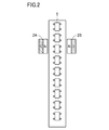
- FIG. 2 is a diagram illustrating a plurality of magnetic sensors 5 attached to the guide 10 based on the first embodiment.
- the plurality of magnetic sensors 5 are arranged at predetermined intervals along the ascending / descending direction.
- the float 20 is provided with a float magnet 2 (hereinafter also simply referred to as a magnet 2). Specifically, magnets 2A and 2B are attached as magnet units. A magnet unit is composed of the magnets 2A and 2B.
- the plurality of magnetic sensors 5 detect the magnetic flux density according to the lifting / lowering operation of the magnet 2 attached to the float 20 and output an electric signal corresponding to the magnetic flux density.
- the configuration of the 4-pin magnetic sensor 5 will be described as an example.
- the number of pins is not particularly limited to this, and those skilled in the art can appropriately change the design.
- FIG. 3 is a circuit configuration diagram of the liquid level detection device 1 based on the first embodiment.
- liquid level detection device 1 based on Embodiment 1 includes a plurality of magnetic sensors (AMR elements) 5 and a detection circuit 50. In this example, a case where n magnetic sensors are provided is shown.
- the detection circuit 50 includes an A / D circuit 60 that is an analog / digital conversion circuit, a P / S conversion circuit 30 that is a parallel / serial conversion circuit, and an MPU (Micro-processing unit) 40 that executes arithmetic processing. .
- a / D circuit 60 that is an analog / digital conversion circuit
- P / S conversion circuit 30 that is a parallel / serial conversion circuit
- MPU Micro-processing unit
- the A / D circuit 60 is connected to a plurality (n) of magnetic sensors 5 and converts an input analog signal into a digital signal.
- the P / S conversion circuit 30 converts the digital signal input from the A / D circuit 60 input in parallel in synchronization with the clock CLK input from the MPU 40 in series and outputs it to the MPU 40.
- the MPU 40 detects the position of the float 20 by performing arithmetic processing on signals from a plurality (n) of magnetic sensors 5 input from the P / S conversion circuit 30.
- the MPU 40 in this example will be described with respect to the signal from the A / D circuit 60 that receives the output of the P / S conversion circuit 30 synchronized with the clock CLK. It is also possible to change to a configuration that receives a digital signal input from the / D circuit 60.
- FIG. 4 is a diagram for explaining the pattern of the magnetoresistive element of the magnetic sensor 5 based on the first embodiment.
- magnetic sensor 5 has a bridge structure composed of four magnetoresistive elements MR1 to MR4 (also collectively referred to as magnetoresistive elements MR).
- the magnetic sensor 5 When the magnetic field is applied, the magnetic sensor 5 outputs signals V + and V ⁇ according to the resistance value change by the resistance value changes of the magnetoresistive elements MR1 to MR4. The magnetic sensor 5 outputs a difference ⁇ V between the signals V + and V ⁇ .
- the magnetoresistive element MR of the magnetic sensor 5 is an anisotropic magnetoresistive element and has a folded pattern structure.
- the resistance value of the magnetoresistive element MR when a magnetic field is applied is minimized when a saturation magnetic field (90 °) perpendicular to the length direction (current direction) of the element is applied, and a parallel saturation magnetic field (0 °) is generated. It has the maximum characteristics when applied.
- the magnetic sensor 5 is provided with bias magnets 3A and 3B.
- the bias magnets 3A and 3B are arranged so that a bias magnetic field is applied to the magnetoresistive elements MR1 to MR4 from the upper left to the lower right.
- the magnetoresistive element MR of the magnetic sensor 5 of this example will be described as a folded pattern structure as an example.
- the pattern structure is not limited to a folded shape, and those skilled in the art can improve the detection characteristics of the magnetic sensor 5. If so, the design can be changed as appropriate.
- the arrangement (orientation) of the bias magnets 3A and 3B in this example, a configuration in which a bias magnetic field vector having an angle of 45 ° is applied from the upper left to the lower right is shown as an example. A person skilled in the art can appropriately change the design of the arrangement or angle so as to enhance the detection characteristics of the magnetic sensor 5.
- a configuration in which the bias magnetic field vector is applied based on the two bias magnets 3A and 3B will be described, but it is also possible to apply the bias magnetic field vector using one bias magnet instead of the two bias magnets.
- a bias magnet may be disposed on the substrate on which the magnetoresistive elements MR1 to MR4 are provided, or a bias magnet may be disposed on the back surface of the base.
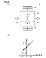
- FIG. 5 is a diagram for explaining the detection principle of the magnetic sensor 5 based on the first embodiment.
- FIG. 5A is a diagram for explaining a bias magnetic field vector that changes in accordance with an external magnetic field.
- the bias magnetic field vector of the magnetic sensor 5 changes its vector direction according to the external magnetic field with respect to the ascending / descending direction.
- the bias magnetic field vector V0 in the absence of an external magnetic field is indicated by a solid line.
- the bias magnet is set so that the magnetic sensor 5 has a magnetic field intensity that reaches the saturation sensitivity region.
- the bias magnetic field vector V0 changes to a bias magnetic field vector V1 according to an external magnetic field (from right to left).
- the bias magnetic field vector V0 changes to the bias magnetic field vector V2 according to the external magnetic field (from left to right).
- the bias magnetic field vector changes according to the change in magnetic flux density of the external magnetic field.
- the magnetic sensor 5 detects a change in the bias magnetic field vector and outputs an output signal (potential difference ⁇ V) corresponding to the detection result.
- FIG. 5B shows the change characteristic of the output signal of the magnetic sensor 5 according to the change of the magnetic flux density of the external magnetic field.
- a predetermined magnetic flux density ST is applied based on the bias magnetic field according to the bias magnets 3A and 3B.
- the output in this case is set to an intermediate value, and the potential difference ⁇ V changes according to the change in the direction of the magnetic field applied to the magnetic sensor 5.
- the potential difference ⁇ V shifts to the ⁇ V1 side in accordance with the change in the magnetic flux density of the external magnetic field from right to left.
- the potential difference ⁇ V shifts to the ⁇ V2 side in accordance with the change in the magnetic flux density of the external magnetic field from the left to the right.
- the saturation magnetic field strength can be increased by changing the magnetic strength of the bias magnets 3A and 3B.
- FIG. 6 is a view for explaining the arrangement of the magnets 2 attached to the float 20 based on the first embodiment.
- FIG. 6 here, a diagram when the float 20 is viewed from above is shown.
- the magnet units formed of the magnets 2A and 2B are provided to face each other with the guide 10 therebetween.
- the N poles of the magnets 2A and 2B are provided so as to face each other. It is also possible to arrange the south poles of the magnets 2A and 2B so as to face each other.
- a magnetic sensor 5 is disposed between the opposing magnets 2A and 2B.
- the direction of magnetic force is in the direction along the guide 10 (the direction in which the float 20 moves up and down), and the magnetic component in the direction perpendicular to the direction along the guide 10 is canceled out.
- the magnetic sensor 5 is arranged so that the center of the magnetic sensor 5, in other words, the center of the region where the magnetoresistive element MR is formed is located between the opposing magnets 2 ⁇ / b> A and 2 ⁇ / b> B. In this case, even if the float 20 rotates, there is almost no change in the direction of magnetic force and magnetic flux density, and the magnetic sensor 5 can accurately measure the amount of displacement of the magnetic flux density.
- the magnets 2A and 2B may not be disposed so that the same poles face each other.
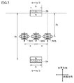
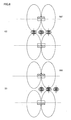
- FIG. 7 is a view for explaining the layout of the magnets 2A and 2B attached to the float 20 and the plurality of magnetic sensors 5 according to the first embodiment.
- magnets 2A and 2B form a set of magnet units.
- the magnet units formed by the magnets 2A and 2B are arranged so that the N poles face each other.
- magnetic sensors 5PA to 5PC are provided as the plurality of magnetic sensors 5 is shown.
- the horizontal distance between the magnet 2A or the magnet 2B and the magnetic sensor 5 is set longer than the distance between the magnetic sensors 5 in the up and down direction. Specifically, when the distance between adjacent magnetic sensors 5 in the ascending / descending direction is a distance a, the distance in the horizontal direction is set to an interval twice the distance a.
- the magnetic sensor 5 is attached to the guide 10 along the raising / lowering direction.
- the case where the three magnetic sensors 5PA to 5PC are arranged to detect the position of the float 20 will be described, but the same applies to the case where a plurality of magnetic sensors are arranged.
- the center in the ascending / descending direction of the magnet 2A and the magnet 2B is set as a reference position (center point).
- the magnetic sensor 5PB is located at the position of the reference position (center point) is shown.
- the three magnetic sensors 5PA to 5PC are arranged so that the bias magnetic field vectors of the magnetic sensors are parallel to the horizontal direction.
- the direction of the bias magnetic field vector is the same as the horizontal direction from the magnet 2B to the magnet 2A.
- the present invention is not limited to this and is the same as the horizontal direction from the magnet 2A to the magnet 2B. You may make it become a direction.
- the white arrows in the horizontal direction of the paper shown in each of the magnetic sensors 5PA to 5PC indicate the maximum magnetic sensing direction of the magnetic sensor. Also, the horizontal arrows on the paper shown in each of the magnetic sensors 5PA to 5PC indicate magnetic fields generated by the bias magnet. However, description up to rotation of the bias magnetic field by the magnetic field of the float magnet is omitted.
- FIG. 8 is a diagram for explaining the relationship with the magnetic sensor when the position of the float 20 based on the first embodiment is changed by the lifting / lowering operation.
- FIG. 8A shows a case where the float 20 moves up and approaches the magnetic sensor 5PA (state S0).
- the magnetic sensor 5PA is affected by the magnetic field (lines of magnetic force) generated by the magnets 2A and 2B of the float 20. Specifically, the magnetic sensor 5PA is affected by a magnetic field from right to left as the magnetic lines of force of the magnets 2A and 2B. Therefore, the bias magnetic field vector V0 of the magnetic sensor 5PA changes to the bias magnetic field vector V1 side. The potential difference ⁇ V decreases as the bias magnetic field vector changes.
- the other magnetic sensors 5PB and 5PC are also affected by the magnetic field from right to left as the magnetic lines of force of the magnets 2A and 2B. The potential difference ⁇ V decreases as the bias magnetic field vector V1 changes.
- FIG. 8B shows the case where the float 20 has further increased by the distance a (state S1) from FIG. 8A.
- the magnetic sensor 5PA is in a state of being positioned on the center line between the float 20 and the magnets 2A and 2B. In this example, this state is the initial state.
- the magnetic sensor 5PB is affected by the magnetic field from right to left as the magnetic lines of force of the magnets 2A and 2B. Therefore, the bias magnetic field vector V0 of the magnetic sensor 5PB changes to the bias magnetic field vector V1 side. The potential difference ⁇ V decreases as the bias magnetic field vector changes.
- the other magnetic sensor 5PC is also affected by the magnetic field from right to left as the magnetic lines of force of the magnets 2A and 2B. The potential difference ⁇ V decreases as the bias magnetic field vector V1 changes.
- FIG. 8C shows a case where the float 20 has further increased by the distance a (state S2) from FIG. 8B.
- the magnetic sensor 5PA is affected by the magnetic field (lines of magnetic force) generated by the magnets 2A and 2B. Specifically, the magnetic sensor 5PA is affected by a magnetic field from left to right as the magnetic lines of force of the magnets 2A and 2B. Therefore, the bias magnetic field vector V0 of the magnetic sensor 5PA changes toward the bias magnetic field vector V2. The potential difference V increases as the bias magnetic field vector V2 changes.
- the magnetic sensor 5PB is in a state of being located on the center line between the magnets 2A and 2B. Therefore, it is an initial state.
- the magnetic sensor 5PC is affected by the magnetic field generated by the magnets 2A and 2B. Specifically, the magnetic sensor 5PC is affected by a magnetic field from right to left as the magnetic lines of force of the magnets 2A and 2B.
- the potential difference ⁇ V decreases as the bias magnetic field vector V1 changes.
- FIG. 8D shows the case where the float 20 has further increased the distance a from FIG. 8C (state S3).
- the magnetic sensor 5PB is affected by the magnetic field (lines of magnetic force) generated by the magnets 2A and 2B. Specifically, the magnetic sensor 5PB is affected by a magnetic field from left to right as the magnetic lines of force of the magnets 2A and 2B. Therefore, the bias magnetic field vector V0 of the magnetic sensor 5PB changes to the bias magnetic field vector V2. The potential difference ⁇ V increases as the bias magnetic field vector V2 changes.
- the magnetic sensor 5PA is affected by the magnetic field from left to right as the magnetic lines of force of the magnets 2A and 2B. Since the influence of the magnetic field is small, the change toward the bias magnetic field vector V2 is small.
- the magnetic sensor 5PC is in a state located on the center line between the magnets 2A and 2B. Therefore, it is an initial state.
- FIG. 8 (E) shows a case where the float 20 has further increased by the distance a (state S4) from FIG. 8 (D).
- the magnetic sensor 5PC is affected by the magnetic field (lines of magnetic force) generated by the magnets 2A and 2B. Specifically, the magnetic sensor 5PC is affected by a magnetic field from left to right as the magnetic lines of force of the magnets 2A and 2B.
- the bias magnetic field vector V0 of the magnetic sensor 5PC changes to the bias magnetic field vector V2.
- the potential difference ⁇ V increases as the bias magnetic field vector V2 changes.
- the magnetic sensors 5PA and 5PB a case where a magnetic field is applied in the up-and-down direction by the magnetic field generated by the magnets 2A and 2B is shown. Specifically, the magnetic sensors 5PA and 5PB are affected by a magnetic field from left to right as a magnetic field (lines of magnetic force) generated by the magnets 2A and 2B. Since the influence of the magnetic field is reduced according to the distance, the change to the bias magnetic field vector V2 side is reduced.
- FIG. 8 (F) shows a case where the float 20 has further increased by the distance a (state S5) from FIG. 8 (E).
- a magnetic field is applied in the up and down direction by the magnetic field generated by the magnets 2A and 2B.
- the magnetic sensors 5PA, 5PB, and 5PC are affected by a magnetic field from left to right as a magnetic field (lines of magnetic force) generated by the magnets 2A and 2B. Since the influence of the magnetic field is reduced according to the distance, the change to the bias magnetic field vector V2 side is reduced. The same applies thereafter.
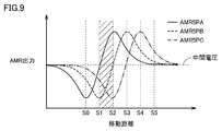
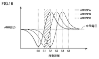
- FIG. 9 is a diagram for explaining output signal waveforms of a plurality of magnetic sensors following the lifting / lowering operation of the float 20 based on the first embodiment.
- the positional relationship between the states S0 to S5 and the output signal relationship are shown. For example, focusing on the magnetic sensor 5PA, a signal corresponding to the magnetic flux density of the external magnetic field received by the magnetic sensor 5PA is output.
- the magnetic sensor 5PA is affected by the magnetic field from right to left as the magnetic lines of force of the magnets 2A and 2B. Therefore, the bias magnetic field vector V0 of the magnetic sensor 5PA changes to the bias magnetic field vector V1 side. The potential difference ⁇ V decreases as the bias magnetic field vector V1 changes.
- the other magnetic sensors 5PB and 5PC are also affected by the magnetic field from the right to the left as the magnetic lines of force of the magnets 2A and 2B, so that the potential difference ⁇ V decreases as the bias magnetic field vector V1 changes.
- the magnetic sensor 5PA In the state S1, the magnetic sensor 5PA is in an initial state located on the center line between the magnets 2A and 2B.
- the voltage of the output signal (potential difference ⁇ V) in the initial state is an intermediate value. (Intermediate voltage).
- the magnetic sensor 5PA shows a case where the output signal (potential difference ⁇ V) decreases.
- a waveform is shown in which the output signal of the magnetic sensor 5PA is shifted by a distance a (90 ° as a phase).
- Focusing on the magnetic sensor 5PC a waveform is shown in which the output signal of the magnetic sensor 5PB is shifted by a distance a (90 ° as a phase).
- FIG. 10 is an image view in which the predetermined area of FIG. 9 is enlarged. Referring to FIG. 10, here, output signal waveforms of a plurality of magnetic sensors 5PA to 5PC in the hatching area of FIG. 9 are shown as the predetermined area.
- the output signal waveforms of the magnetic sensors 5PA and 5PB are modeled (approximated) to a horizontal component (component in the up-and-down direction) of the magnetic vector P of an external magnetic field that changes along a circular shape, which will be described later, when the intermediate voltage is used as a reference. It is possible.
- one output signal (electric signal) can be represented by a sine wave (sin ⁇ ) and the other output signal (electric signal) can be represented by a cosine wave (cos ⁇ ). Then, the angle ⁇ of the magnetic vector P of the external magnetic field is calculated based on the two output signals (electric signals).
- the output signal of the magnetic sensor 5PA is represented as Psin ⁇
- the output signal of the magnetic sensor 5PB is represented as ⁇ Pcos ⁇
- the angle ⁇ is calculated from the following equation.
- ⁇ arctan (Psin ⁇ /
- an electrical signal output from two adjacent magnetic sensors among the output signals of a plurality of magnetic sensors is detected to calculate the angle of the magnetic vector of the external magnetic field, and the calculated angle of the magnetic vector
- the position of the float is detected based on the above.
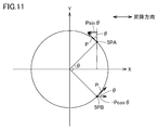
- FIG. 11 is a diagram schematically illustrating the relationship between the magnetic sensor 5 and the magnetic vector P based on the first embodiment.
- FIG. 11 shows magnetic vectors with respect to the lifting / lowering direction of the float 20 with respect to the magnetic sensors 5PA and 5PB when the state S1 is shifted to the state S2.
- the raising / lowering direction is a direction along the X-axis.
- the magnetic vector P indicates the direction of the magnetic field lines of the magnetic field generated by the N pole of the magnet 2A.
- the magnetic field lines of the magnetic field generated by the N pole of the magnet 2B are omitted, but the component perpendicular to the ascending / descending direction of the magnetic vector P is the magnetic field generated by the N pole of the magnet 2B. It is canceled out by the magnetic vector of the magnetic field lines. Therefore, the external magnetic field for the magnetic sensors 5PA and 5PB has only the up-down direction component. As described above, the bias magnetic field vector in each magnetic sensor 5 changes according to the external magnetic field.
- the output signal detected by the magnetic sensor 5PA in the up-and-down direction is Psin ⁇
- the output signal detected by the magnetic sensor 5PB is ⁇ Pcos ⁇ .
- it calculates as angle (theta) of the magnetic vector P based on two output signals (electrical signal).
- tan ⁇ (Psin ⁇ /
- the above process is a process executed by the detection circuit 50. Specifically, the calculation process is executed in the MPU 40.
- the position of the float 20 changes by a distance a corresponding to a change of 0 ° to 90 ° as the angle information ⁇ of the magnetic vector.
- the center in the ascending / descending direction of the magnets 2A and 2B is set as a reference position (center point) as an example.
- the reference position (center point) of the float 20 shown in the state S1 in FIG. 8B is the same position as the position of the magnetic sensor 5PA.
- the angle information ⁇ of the magnetic vector is calculated using the electrical signals of the magnetic sensor 5PA and the magnetic sensor 5PB, and the positional relationship is determined. For example, when the angle information ⁇ is calculated as 45 °, it is detected that the reference position (center point) of the float is a position moved by a / 2 distance from the position of the magnetic sensor 5PA toward the magnetic sensor 5PB. Is possible.
- the positional information from the magnetic sensor 5PA is determined by calculating the angle information ⁇ of the magnetic vector using the electrical signals of the magnetic sensors 5PA and 5PB has been described. It is also possible to determine the positional relationship from Of course, it is possible to determine the positional relationship from the magnetic sensor 5PB by calculating the angle information ⁇ of the magnetic vector using the electrical signals of the magnetic sensors 5PB and 5PC according to the same method. The same applies to other systems.
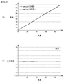
- FIG. 12 is a diagram illustrating the accuracy of the angle information ⁇ based on the first embodiment.
- FIG. 12A shows arctan ⁇ when one output signal (electrical signal) is set to Pcos ⁇ and the other output signal (electrical signal) is set to Psin ⁇ when the angle ⁇ is changed from 0 ° to 90 °. And a comparison with the reference value is shown.
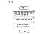
- FIG. 13 is a flowchart for explaining the detection method of the liquid level detection apparatus 1 based on the first embodiment.
- two signals based on a predetermined combination of signal relationships are extracted (step SP2).
- two output signals are extracted: an output signal from a magnetic sensor that exceeds the intermediate voltage, and a signal from a magnetic sensor that is adjacent to the magnetic sensor and that is equal to or lower than the intermediate voltage.
- the intermediate voltage is set to the voltage of the output signal in the initial state as an example.
- the magnetic sensor 5PA is located on the center line between the magnets 2A and 2B, and the intermediate voltage can be set by measuring the voltage in advance. It is.
- the intermediate voltage may be set to an intermediate value between the maximum value and the minimum value of the peak value.
- the angle ⁇ of the magnetic vector is calculated based on the extracted two signals (step SP4). Specifically, one output signal (electric signal) of the two electric signals is set to Pcos ⁇ , and the other output signal (electric signal) is set to Psin ⁇ , and magnetism is performed based on the two output signals (electric signals). The angle ⁇ of the vector is calculated. Then, tan ⁇ is calculated based on the two output signals (electrical signals), and the angle information ⁇ is calculated by calculating arctan ⁇ .
- the position of the float 20 is calculated based on the angle ⁇ of the magnetic vector (step SP6).
- the reference position (center point) of the float 20 is calculated from the position of the magnetic sensor. For example, if the angle information ⁇ is calculated as 45 ° as described above, the reference position (center point) of the float is a distance a / 2 from the position of the magnetic sensor 5PA, on the magnetic sensor 5PB side. It is possible to detect that it is in the moved position.
- the liquid level detection device 1 enables highly accurate position detection of the float 20 based on two output signals (electrical signals). With this method, there is no need to provide a switching circuit for switching signals, the circuit configuration can be simplified, and the size can be reduced.
- the output signal may change due to changes in the characteristics of the magnet or the magnetic sensor following the change in the environmental temperature.
- tan ⁇ (Psin ⁇ / Pcos ⁇ ) of the two output signals is calculated. Therefore, the fluctuation amount according to the environmental temperature is canceled out, so that the error due to the influence of the environmental temperature is reduced, and the position detection with high accuracy is possible.
- the case where the horizontal distance between the magnet 2A or the magnet 2B and the magnetic sensor 5 is set longer than the distance between the magnetic sensors 5 in the ascending / descending direction has been described.
- the case where the distance between the adjacent magnetic sensors 5 in the ascending / descending direction is set to the distance a and the distance in the horizontal direction is set to twice the distance a has been described.
- the thickness direction (N pole and S pole width) of the magnet 2A, etc. the distance between the magnetic sensors 5 or the horizontal distance between the magnets and the magnetic sensor is appropriately designed while improving the detection characteristics of the magnetic sensor 5. It is possible to change.
- the length of the float 20 can be reduced, and the circuit configuration can be simplified and miniaturized. In addition, the cost of the liquid level detection device can be reduced.
- the magnetic sensor 5 based on Embodiment 1 can respond also to the shift
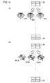
- FIG. 14 is a diagram for explaining the external magnetic field applied to the bias magnetic field vector due to the shift of the float 20.
- FIG. 14A is a diagram for explaining the states of the magnetic sensors 5PA to 5PC based on the first embodiment.
- the bias magnetic field vectors of the adjacent magnetic sensors 5PA and 5PB among the magnetic sensors 5PA to 5PC are not only the external magnetic field including only the vertical direction component by the magnet 2B but also the external magnetic field including the horizontal direction component.
- the external magnetic field applied to the bias magnetic field vector of the magnetic sensor 5PA and the external magnetic field applied to the bias magnetic field vector of the magnetic sensor 5PB are substantially proportional to each other.
- the two output signals of the magnetic sensors 5PA and 5PB are both affected by the shift of the float 20.
- the amplitude value changes due to the above effect. That is, a fluctuation occurs in the amplitude value when setting one output signal (electric signal) of the two electric signals to Pcos ⁇ and the other output signal (electric signal) to Psin ⁇ . Since the offset is based on the above-described formula, the calculation of the angle information ⁇ is hardly affected.
- FIG. 14B is a diagram for explaining the states of the magnetic sensors 5PA # to 5PC # as comparative examples.
- the bias magnetic field vectors of the magnetic sensors 5PA # to 5PC # are not parallel to the vertical direction and the horizontal direction but are inclined in a predetermined direction. As an example, the case where it is inclined 45 ° with respect to the horizontal direction is shown.
- the bias magnetic field vectors of the adjacent magnetic sensors 5PA # and 5PB # among the magnetic sensors 5PA # to 5PC # include not only an external magnetic field only in the vertical direction component by the magnet 2B but also an external magnetic field including a horizontal direction component. Take it.
- the bias magnetic field vector of the magnetic sensor 5PB # changes greatly.
- the magnetic sensor 5PA # and the float 20 are hardly affected by the deviation of the float 20, while the magnetic sensor 5PB # is greatly influenced by the deviation of the float 20. Due to the above influence, the calculation of the angle information ⁇ is greatly affected, and the accuracy is deteriorated.
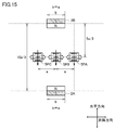
- FIG. 15 is a diagram for explaining a layout of the magnets 2A and 2B attached to the float 20 and a plurality of magnetic sensors 5 based on the modification of the first embodiment.
- the magnets 2 ⁇ / b> A and 2 ⁇ / b> B form a set of magnet units.
- the magnet units formed by the magnets 2A and 2B are arranged so that the N poles face each other.
- the horizontal distance between the magnet 2A or the magnet 2B and the magnetic sensor 5 is set longer than the distance between the magnetic sensors 5 in the up and down direction. Specifically, when the distance between adjacent magnetic sensors 5 in the up-and-down direction is a distance a, the horizontal distance is set to an interval 5/3 times the distance a.
- the magnetic sensor 5 is attached to the guide 10 along the raising / lowering direction.
- the case where the three magnetic sensors 5PA to 5PC are arranged to detect the position of the float 20 will be described, but the same applies to the case where a plurality of magnetic sensors are arranged.
- FIG. 16 is a diagram for explaining output signal waveforms of a plurality of magnetic sensors according to the lifting / lowering operation of the float 20 based on the modification of the first embodiment.
- a signal corresponding to the magnetic flux density of the external magnetic field received by the magnetic sensor 5PA is output.
- the magnetic sensor 5PA is affected by the magnetic field from right to left as the magnetic lines of force of the magnets 2A and 2B. Therefore, the bias magnetic field vector V0 of the magnetic sensor 5PA changes to the bias magnetic field vector V1 side. The potential difference ⁇ V decreases as the bias magnetic field vector V1 changes.
- the other magnetic sensors 5PB and 5PC are also affected by the magnetic field from the right to the left as the magnetic lines of force of the magnets 2A and 2B, so that the potential difference ⁇ V decreases as the bias magnetic field vector V1 changes.
- the magnetic sensor 5PA In the state S1, the magnetic sensor 5PA is in an initial state located on the center line between the magnets 2A and 2B.
- the voltage of the output signal (potential difference ⁇ V) in the initial state is an intermediate value. (Intermediate voltage).
- the magnetic sensor 5PA shows a case where the output signal (potential difference ⁇ V) decreases.
- a waveform is shown in which the output signal of the magnetic sensor 5PA is shifted by a distance a (90 ° as a phase).
- Focusing on the magnetic sensor 5PC a waveform is shown in which the output signal of the magnetic sensor 5PB is shifted by a distance a (90 ° as a phase).
- the signal waveform is different from the output signal waveform of the magnetic sensor in FIG. 9, and the signal waveform deviates from the ideal sin wave and cos wave. Thereby, the precision of the position of the float 20 may deteriorate.
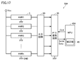
- FIG. 17 is a circuit configuration diagram of the liquid level detection device 1 based on a modification of the first embodiment.
- liquid level detection device 1 based on a modification of the first embodiment includes a plurality of magnetic sensors (AMR elements) 5 and a detection circuit 50 #. In this example, a case where n magnetic sensors are provided is shown.
- the detection circuit 50 # includes an A / D circuit 60 that is an analog / digital conversion circuit, a P / S conversion circuit 30 that is a parallel / serial conversion circuit, and an MPU (Micro-processing unit) 40 # that executes arithmetic processing. including.
- the MPU 40 # detects the position of the float 20 by performing arithmetic processing on signals from a plurality (n) of magnetic sensors 5 input from the P / S conversion circuit 30. Specifically, MPU 40 # further includes a correction unit 45.
- the correction unit 45 corrects the signal from the magnetic sensor 5.
- two signals are extracted: a magnetic sensor signal that exceeds the intermediate voltage among the corrected output signals of the plurality of magnetic sensors, and a magnetic sensor signal that is adjacent to the magnetic sensor and that is equal to or lower than the intermediate voltage.
- the electrical signals output from the two extracted magnetic sensors are detected to calculate the angle of the magnetic vector of the external magnetic field, and the position of the float is detected based on the calculated angle of the magnetic vector.
- FIG. 18 is a diagram for explaining signals before and after correction of the magnetic sensors 5PA and 5PB based on the modification of the first embodiment.
- FIG. 18 (A) shows output signals detected by the magnetic sensors 5PA and 5PB before correction.
- the output signal of the magnetic sensor (AMR) 5PA is represented by Psin ⁇
- the output signal of the magnetic sensor (AMR) 5PB is represented by -Pcos ⁇ .
- a signal obtained by inverting the output signal of the magnetic sensor 5PB is shown.
- the ratio of the signal waveform of the output signal is the same as the ideal ratio of sin wave and cos wave, it is possible to detect the position without error, but the ratio of the signal waveform of the actual output signal to the ideal Since there is a deviation between the ratio of the sin wave and the cos wave, the angular accuracy varies.
- the signal waveform can be approximated to an ideal sin waveform and cos waveform by raising the value of the AMR output for each angle by a predetermined coefficient. Then, by using the above-described equation of angle ⁇ , it is possible to derive an angle with improved accuracy.
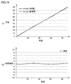
- FIG. 19 is a diagram illustrating the accuracy of the angle information ⁇ based on the modification of the first embodiment.
- FIG. 19A shows arctan ⁇ when one output signal (electrical signal) is set to Pcos ⁇ and the other output signal (electrical signal) is set to Psin ⁇ when the angle ⁇ is changed from 0 ° to 90 °. And a comparison with the reference value is shown.
- the accuracy of the angle shows a case where there is almost no deviation from the reference value, and the deviation of less than ⁇ 2 ° is detected and the position of the float 20 is detected with high accuracy. Is possible.
- the N pole and the S pole of the magnetic poles of the magnet provided in the float 20 may be arranged in the ascending / descending direction.
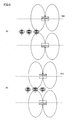
- FIG. 20 is a diagram for explaining the layout of the magnets attached to the float 20 and the magnetic sensors 5PA, 5PB, and 5PC based on the second embodiment.
- magnets 2C and 2D are provided as separate magnet units.
- the magnets 2C and 2D are arranged in a positional relationship in which the north and south poles of each magnet are arranged in the same direction in the ascending / descending direction. With this configuration, the position of the float 20 can be detected based on the same method as described above.
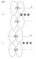
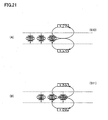
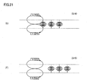
- FIG. 21 is a diagram for explaining the relationship with the magnetic sensor when the position of the float 20 based on the second embodiment is changed by the lifting / lowering operation.
- FIG. 21 (A) shows a case where the float 20 rises and approaches the magnetic sensor 5PA (state S10).
- the magnetic sensor 5PA is affected by a magnetic field (lines of magnetic force) generated by the magnets 2C and 2D of the float 20. Specifically, the magnetic sensor 5PA is affected by the magnetic field from right to left as the magnetic lines of force of the magnets 2C and 2D. Therefore, the bias magnetic field vector V0 of the magnetic sensor 5PA changes to the bias magnetic field vector V1 side. The potential difference ⁇ V decreases as the bias magnetic field vector changes.
- the other magnetic sensors 5PB and 5PC are also affected by the magnetic field from right to left as the magnetic lines of force of the magnets 2C and 2D. The potential difference ⁇ V decreases as the bias magnetic field vector V1 changes.
- the magnetic sensor 5PA is less affected by the magnetic field from right to left as the magnetic lines of force of the magnets 2C and 2D.
- FIG. 21 (B) shows the case where the float 20 has further increased the distance a from FIG. 21 (A) (state S11).
- the magnetic sensor 5PA is in a state of being located on the center line between the magnets 2C and 2D. Specifically, the magnetic sensor 5PA is affected by a magnetic field from left to right as the magnetic lines of force of the magnets 2C and 2D. Therefore, the bias magnetic field vector V0 of the magnetic sensor 5PA changes toward the bias magnetic field vector V2.
- the potential difference V increases (becomes maximum) in accordance with the change toward the bias magnetic field vector V2.
- the external magnetic field with respect to the bias magnetic field vector V0 is eliminated as the magnetic lines of force of the magnets 2C and 2D, and the case is not changed.
- the other magnetic sensor 5C is affected by the magnetic field from right to left as the magnetic lines of force of the magnets 2C and 2D.
- the potential difference ⁇ V decreases as the bias magnetic field vector V1 changes.
- FIG. 21 (C) shows a case where the float 20 has further increased by a distance a (state S12) from FIG. 21 (B).
- the magnetic sensor 5PA is less affected by the magnetic field from the left to the right as the magnetic lines of force in the up-and-down direction of the magnets 2C and 2D.
- the magnetic sensor 5PB is in a state located on the center line between the magnets 2C and 2D. Specifically, the magnetic sensor 5PB is affected by a magnetic field from left to right as the magnetic lines of force of the magnets 2C and 2D. Therefore, the bias magnetic field vector V0 of the magnetic sensor 5PB changes to the bias magnetic field vector V2. The potential difference V increases (becomes maximum) in accordance with the change toward the bias magnetic field vector V2.
- the external magnetic field with respect to the bias magnetic field vector V0 disappears as the magnetic force lines of the magnets 2C and 2D, and the magnetic sensor 5PC does not change.
- FIG. 21 (D) shows the case where the float 20 has further increased the distance a from FIG. 21 (C) (state S13).
- the magnetic sensor 5PA is affected by the magnetic field from right to left as the magnetic lines of force of the magnets 2C and 2D. Therefore, the bias magnetic field vector V0 of the magnetic sensor 5PA changes to the bias magnetic field vector V1 side. The potential difference ⁇ V decreases as the bias magnetic field vector changes.
- the magnetic sensor 5PB shows a case where the external magnetic field with respect to the bias magnetic field vector V0 of the magnetic sensor 5PB disappears and does not change.
- the magnetic sensor 5PC is in a state of being located on the center line between the magnets 2C and 2D. Specifically, the magnetic sensor 5PC is affected by a magnetic field from left to right as the magnetic lines of force of the magnets 2C and 2D. Therefore, the bias magnetic field vector V0 of the magnetic sensor 5PC changes toward the bias magnetic field vector V2. The potential difference V increases (becomes maximum) in accordance with the change toward the bias magnetic field vector V2.
- FIG. 21 (E) shows the case where the float 20 has further increased the distance a from FIG. 21 (D) (state S14).
- the magnetic sensors 5PA and 5PB are affected by the magnetic field from right to left as the magnetic lines of force of the magnets 2C and 2D. Therefore, the bias magnetic field vector V0 of the magnetic sensors 5PA and 5PB changes to the bias magnetic field vector V1 side.
- the potential difference ⁇ V decreases as the bias magnetic field vector changes.
- FIG. 21 (F) shows a case where the float 20 has further increased by the distance a (state S15) from FIG. 21 (E).
- the magnetic sensors 5PA, 5PB, and 5PC are affected by the magnetic field from right to left as the magnetic lines of force of the magnets 2C and 2D. Therefore, the bias magnetic field vector V0 of the magnetic sensors 5PA, 5PB, and 5PC changes to the bias magnetic field vector V1 side.
- the potential difference ⁇ V decreases as the bias magnetic field vector changes.
- FIG. 22 is a diagram for explaining output signal waveforms of a plurality of magnetic sensors according to the lifting / lowering operation of the float 20 according to the second embodiment.
- a signal corresponding to the magnetic flux density of the external magnetic field received by the magnetic sensor 5PA is output.
- the magnetic sensor 5PA does not change according to the external magnetic field of the magnets 2C and 2D is shown.
- the magnetic sensor 5PB For the magnetic sensor 5PB, the case where the magnetic sensor 5PB does not change according to the external magnetic field of the magnets 2C and 2D is shown. The case where the output signal of the magnetic sensor 5PB is a predetermined voltage value is shown.
- the case where the magnetic sensor 5PA does not change according to the external magnetic field of the magnets 2C and 2D is shown.
- the case where the output signal of the magnetic sensor 5PA is a predetermined voltage value is shown.
- the case where the output signal of the magnetic sensor 5PB is maximized when it changes to the bias magnetic field vector V2 side in accordance with the external magnetic field of the magnets 2C and 2D is shown.
- the case where the magnetic sensor 5PC does not change according to the external magnetic field of the magnets 2C and 2D is shown for the magnetic sensor 5PC.
- the case where the output signal of the magnetic sensor 5PC is a predetermined voltage value is shown.
- the magnetic sensor 5PB does not change according to the external magnetic field of the magnets 2C and 2D is shown.
- the magnetic sensor 5PC the case where the output signal of the magnetic sensor 5PC becomes maximum when it changes to the bias magnetic field vector V2 side in accordance with the external magnetic field of the magnets 2C and 2D is shown.
- the magnetic sensor 5PA does not change according to the external magnetic field of the magnets 2C and 2D is shown for the magnetic sensor 5PA.
- Focusing on the magnetic sensor 5PB a waveform obtained by shifting the output signal of the magnetic sensor 5PA by a distance a (90 ° as a phase) is shown. Focusing on the magnetic sensor 5PC, a waveform is shown in which the output signal of the magnetic sensor 5PB is shifted by a distance a (90 ° as a phase).
- FIG. 23 is an enlarged image of the predetermined area in FIG. Referring to FIG. 23, here, output signal waveforms of a plurality of magnetic sensors 5PA and 5PB in the hatching area of FIG. 22 as a predetermined area are shown.
- the output signal waveforms of the magnetic sensors 5PA and 5PB are modeled (approximated) to a horizontal component (component in the ascending / descending direction) of the magnetic vector P of an external magnetic field that changes along a circular shape to be described later when a predetermined voltage is used as a reference. It is possible.
- one output signal (electric signal) can be represented by a sine wave (sin ⁇ ) and the other output signal (electric signal) can be represented by a cosine wave (cos ⁇ ). Then, the angle ⁇ of the magnetic vector P of the external magnetic field is calculated based on the two output signals (electric signals).
- an electrical signal output from two adjacent magnetic sensors among the output signals of a plurality of magnetic sensors is detected to calculate the angle of the magnetic vector of the external magnetic field, and the calculated angle of the magnetic vector
- the position of the float is detected based on the above.
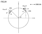
- FIG. 24 is a diagram schematically illustrating the relationship between the magnetic sensor 5 and the magnetic vector P based on the second embodiment.
- FIG. 24 shows magnetic vectors with respect to the lifting / lowering direction of the float 20 with respect to the magnetic sensors 5PA and 5PB in the case of transition from the state S11 to the state S12.
- the raising / lowering direction is a direction along the X-axis.
- the magnetic vector P indicates the direction of the magnetic field lines of the magnetic field generated by the N pole of the magnet 2C.
- the magnetic field lines of the magnetic field generated by the N pole of the magnet 2D are omitted, but the component perpendicular to the ascending / descending direction of the magnetic vector P is the magnetic field generated by the N pole of the magnet 2D. It is canceled out by the magnetic vector of the magnetic field lines. Therefore, the external magnetic field for the magnetic sensors 5PA and 5PB has only the up-down direction component. As described above, the bias magnetic field vector in each magnetic sensor 5 changes according to the external magnetic field.
- the output signal detected by the magnetic sensor 5PA in the up-and-down direction is represented by Pcos ⁇
- the output signal detected by the magnetic sensor 5PB is represented by Psin ⁇ . It is possible. And it calculates as angle (theta) of the magnetic vector P based on two output signals (electrical signal).
- tan ⁇ (Psin ⁇ / P cos ⁇ ) is calculated based on two output signals (electrical signals), and angle information ⁇ is calculated by calculating arctan ⁇ .
- the above process is a process executed by the detection circuit 50. Specifically, the calculation process is executed in the MPU 40.
- the position of the float 20 changes by a distance a corresponding to a change of 0 ° to 90 ° as the angle information ⁇ of the magnetic vector.
- the center in the ascending / descending direction of the magnets 2C and 2D is set as a reference position (center point) as an example.
- the reference position (center point) of the float 20 shown in the state S11 in FIG. 21B is the same position as the position of the magnetic sensor 5PA.
- the angle information ⁇ of the magnetic vector is calculated using the electrical signals of the magnetic sensor 5PA and the magnetic sensor 5PB, and the positional relationship is determined. For example, when the angle information ⁇ is calculated as 45 °, it is detected that the reference position (center point) of the float is a position moved by a / 2 distance from the position of the magnetic sensor 5PA toward the magnetic sensor 5PB. Is possible.
- the positional information from the magnetic sensor 5PA is determined by calculating the angle information ⁇ of the magnetic vector using the electrical signals of the magnetic sensors 5PA and 5PB has been described. It is also possible to determine the positional relationship from Of course, it is possible to determine the positional relationship from the magnetic sensor 5PB by calculating the angle information ⁇ of the magnetic vector using the electrical signals of the magnetic sensors 5PB and 5PC according to the same method. The same applies to other systems.
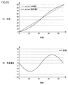
- FIG. 25 is a diagram for explaining the accuracy of the angle information ⁇ based on the second embodiment.
- FIG. 25A shows arctan ⁇ when one output signal (electrical signal) is set to Pcos ⁇ and the other output signal (electrical signal) is set to Psin ⁇ when the angle ⁇ is changed from 0 ° to 90 °. And a comparison with the reference value is shown.
- the accuracy of the angle shows a case where there is only a deviation of ⁇ 6 ° from the reference value, and the position of the float 20 can be detected with high accuracy.
- FIG. 26 is a flowchart illustrating a detection method of the liquid level detection apparatus 1 based on the second embodiment.
- two adjacent signals exceeding both predetermined voltages are extracted (step SP12).
- the predetermined voltage is set to the voltage of the output signal in the initial state as an example.
- the bias magnetic field vector of the magnetic sensor 5PA does not change, and the predetermined voltage can be set by measuring the voltage in advance.
- step SP14 two electrical signals in the region surrounded by the dotted line described in FIG. 22 are extracted.
- the magnetic vector angle ⁇ is calculated based on the two extracted signals (step SP14). Specifically, one output signal (electric signal) of the two electric signals is set to Pcos ⁇ , and the other output signal (electric signal) is set to Psin ⁇ , and magnetism is performed based on the two output signals (electric signals). The angle ⁇ of the vector is calculated. Then, tan ⁇ is calculated based on the two output signals (electrical signals), and the angle information ⁇ is calculated by calculating arctan ⁇ .
- the position of the float 20 is calculated based on the angle ⁇ of the magnetic vector (step SP16).
- the reference position (center point) of the float 20 is calculated from the position of the magnetic sensor. For example, when the angle information ⁇ is calculated as 45 ° as described above, the reference position (center point) of the float is a distance of a / 2 from the position of the magnetic sensor 5A, on the magnetic sensor 5B side. It is possible to detect that it is in the moved position.
- the liquid level detection apparatus 1 can detect the position of the float 20 with high accuracy based on two electrical signals. With this method, there is no need to provide a switching circuit for switching signals, the circuit configuration can be simplified, and the size can be reduced.
- the correction unit 45 may correct the signal from the magnetic sensor 5.
- FIG. 27 is a diagram illustrating signals before and after correction of the magnetic sensors 5PA and 5PB.
- FIG. 27 (A) shows output signals detected by the magnetic sensors 5PA and 5PB before correction.
- the output signal of the magnetic sensor (AMR) 5PA is represented by Pcos ⁇
- the output signal of the magnetic sensor (AMR) 5PB is represented by Psin ⁇ .
- the signal waveform of the output signal is an ideal sine wave and cos wave, it is possible to detect the position without error. As a result, the angular accuracy varies.
- FIG. 27B shows the output signals of the corrected magnetic sensors (AMR) 5PA and 5PB.
- the angle of the magnetic vector of the external magnetic field is calculated based on the corrected signal, and the position of the float is detected based on the calculated angle of the magnetic vector.
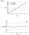
- FIG. 28 is a diagram illustrating the accuracy of the angle information ⁇ based on the modification of the second embodiment.
- FIG. 28A shows arctan ⁇ when one output signal (electrical signal) is set to Pcos ⁇ and the other output signal (electrical signal) is set to Psin ⁇ when the angle ⁇ is changed from 0 ° to 90 °. And a comparison with the reference value is shown.
- the position of the float 20 can be detected with high accuracy, and the circuit configuration is simplified. It is possible to reduce the size.
- FIG. 29 is a diagram illustrating a layout of the magnet 2B attached to the float 20 according to the third embodiment and the plurality of magnetic sensors 5.
- the magnet 2A is removed to form a magnet unit including only the magnet 2B.
- the configuration of the third embodiment it is possible to detect the position of the float 20 with high accuracy based on the two electrical signals in the same manner as the liquid level detection device 1 based on the first embodiment. With this method, there is no need to provide a switching circuit for switching signals, the circuit configuration can be simplified, and the size can be reduced.
- 1 liquid level detection device 2 magnets, 5, 5 PA to 5 PC magnetic sensor, 10 guide, 20 float, 30 P / S conversion circuit, 40, 40 # MPU, 45 correction unit, 50, 50 # detection circuit, 60 A / D circuit.
Landscapes
- Physics & Mathematics (AREA)
- Fluid Mechanics (AREA)
- General Physics & Mathematics (AREA)
- Level Indicators Using A Float (AREA)
Abstract
液面検出装置は、液面に追従して昇降するフロートと、フロートに取り付けられるフロート磁石と、フロートの昇降を案内する案内部材と、案内部材に取り付けられ、フロート磁石の昇降位置に応じて変化する磁束密度を検知して、その磁束密度に対応する電気信号を出力する複数の磁気センサと、複数の磁気センサからそれぞれ出力される電気信号に基づいてフロートの位置を検出する検出回路とを備える。昇降方向と垂直な水平方向におけるフロート磁石と磁気センサとの長さは第1の長さに設定され、昇降方向における互いに隣接する磁気センサ間は第2の長さに設定され、第1の長さは、第2の長さよりも長く、検出回路は、複数の磁気センサのうち隣接する2つの磁気センサから出力される電気信号に基づいてフロートの位置を検出する。
Description
本発明は、液面検出装置に関し、具体的には、自動車等のガソリンやエンジンオイルや尿素水などの液体を貯蔵するタンクに搭載され、磁石を利用して液面の位置を検出する液面検出装置に関する。
従来より、磁石と磁気センサとを備える液面検出装置が知られている。例えば、液面の位置の変化に対応して昇降し、磁石を有する浮きと、磁石の磁束密度を検知する磁気センサとを備え、磁気センサの出力信号から液面の位置を検出する液面検出装置が知られている。
この点で、特許文献1には、液面感得体21と、液面感得体21が内部に配置されている液タンク18と、検出ロッド23の上端に設けられた変位磁石24と、複検出部ハウジング20に取り付けられており、複数のホール素子5、5を含む検出器本体25とを備える、液面検出装置が開示されている(図1~図4,図12~図13参照)。
検出器本体25は、変位磁石24の移動方向と平行となるように複数のホール素子5を同一直線上に所要の配設間隔でプリント基板6上に設けた構造を有する。各ホール素子は感磁面5aが変位磁石24の着磁方向と平行になるよう設けられている。液面感得体21は、検出部ハウジング20の下面に上端を取り付けた引張ばね22により検出ロッド23を介してタンク内に吊り下げられていて、検出ロッド23の上端は検出部ハウジング20内に臨んでいる。液面検出装置は、検出部ハウジング20内における検出ロッド23の上端部の変位を変位磁石24の変位として検出器本体25にて検出して液位を測定する。検出器本体25は制御回路7を介して、各ホール素子の出力電圧から磁石の位置を演算してさらに液位値に換算する演算回路8と、同演算回路からの液位値を画面等に出力する出力装置9に接続されている。
特許文献1に記載の液面検出装置では、検出ロッド23及び変位磁石24は、液タンク18の天面に設けられた貫通孔から液タンク18の外部に突出している。このため、特許文献1に記載の液面検出装置と同様に、小型化が困難であるとともに、機器によっては搭載が困難となる可能性がある。
一方で、タンク内に磁石を配置してなる液面検出装置も考案されている。
特許文献2には、マグネット3と、マグネット3が内部に配置されているタンク2と、ロッド4と、複数の磁気強度センサS[1]~S[4]と、制御部10とを備え、マグネット3の位置により液面の位置を検出する、液面検出装置が開示されている(図1、図4、図5参照)。
特許文献2には、マグネット3と、マグネット3が内部に配置されているタンク2と、ロッド4と、複数の磁気強度センサS[1]~S[4]と、制御部10とを備え、マグネット3の位置により液面の位置を検出する、液面検出装置が開示されている(図1、図4、図5参照)。
ロッド4は、長尺の円柱状であり、軸方向が上下方向(鉛直方向)と平行になるようにタンク2内に配置されている。マグネット3は、円環状であり、タンク2内に貯蔵された液体の液面に浮かぶように構成されている。ロッド4はマグネット3に挿通されており、マグネット3はタンク2に貯蔵された液体の液面に浮かべられた状態において、ロッド4によって移動がガイドされて上下方向に移動する。複数の磁気強度センサS[1]~S[4]は、それぞれがロッド4に埋め込まれており、上方から下方に向けて互いに間隔をあけて順次並ぶように配置されている。
制御部10は、切替スイッチ12及び減算器13を有する差分値算出部11と、マイクロコンピュータ20とを有する。切替スイッチ12は、入力端子I11、I12、I13、I21、I22、I23、出力端子O1、O2を有する。マイクロコンピュータ20からの制御信号によるスイッチ切替により入力端子I11、I12、I13のいずれかが出力端子O1に接続される。入力端子I21、I22、I23のいずれかがスイッチ切替により出力端子O2に接続される。入力端子I11は磁気強度センサS[1]と接続されている。入力端子I12は磁気強度センサS[2]と接続されている。入力端子I13は磁気強度センサS[3]と接続されている。入力端子I21は磁気強度センサS[2]と接続されている。入力端子I22は磁気強度センサS[3]と接続されている。入力端子I23は磁気強度センサS[4]と接続されている。これにより、切替スイッチ12は、(1)出力端子O1から磁気強度センサS[1]の電圧信号が出力されているとき、出力端子O2から磁気強度センサS[2]の電圧信号が出力され、(2)出力端子O1から磁気強度センサS[2]の電圧信号が出力されているとき、出力端子O2から磁気強度センサS[3]の電圧信号が出力され、(3)出力端子O1から磁気強度センサS[3]の電圧信号が出力されているとき、出力端子O2から磁気強度センサS[4]の電圧信号が出力される。減算器13は、出力端子O1が接続される一方の入力端子と、出力端子O2が接続される他方の入力端子と、差分電圧信号を出力する出力端子とを備える。
マイクロコンピュータ20は、切替スイッチ12及び減算器13と接続されている。マイクロコンピュータ20は、隣接して配置された磁気強度センサの電圧信号(出力値)の差分値とマグネット3の位置(即ち、タンク2に貯蔵された液体の液面レベル)との関係を示す高精度液面レベル検出基準情報G[1]~G[3]と、標準精度液面レベル検出基準情報H[1]~H[3]、液面レベルの検出において高精度液面レベル検出基準情報G[1]~G[3]及び標準精度液面レベル検出基準情報H[1]~H[3]のいずれを用いるかを判定するための高精度検出条件が予め記憶されているROMを備えている。
マイクロコンピュータ20はCPUをさらに備え、CPUは、減算器13の差分電圧信号と、高精度液面レベル検出基準情報G[1]~G[3]と、標準精度液面レベル検出基準情報H[1]~H[3]と、高精度検出条件を用いた信号処理を行い、マグネット3の位置、即ち、タンク2に貯蔵された液体の液面レベルを検出する。
しかしながら、特許文献2に記載の液面検出装置では、切替スイッチ12、減算器13、マイクロコンピュータ20のROMが必要であるため、回路構成が複雑化するとともに小型化が困難である。
したがって、本発明は、上記の課題を解決するためになされたものであって、回路構成を簡易かつ小型化が可能な液面検出装置を提供することを目的とする。
ある局面に従う液面検出装置は、液面に追従して昇降するフロートと、フロートに取り付けられるフロート磁石と、フロートの昇降を案内する案内部材と、案内部材に取り付けられ、フロート磁石の昇降位置に応じて変化する磁束密度を検知して、その磁束密度に対応する電気信号を出力する複数の磁気センサと、複数の磁気センサからそれぞれ出力される電気信号に基づいてフロートの位置を検出する検出回路とを備える。昇降方向と垂直な水平方向におけるフロート磁石と磁気センサとの長さは第1の長さに設定され、昇降方向における互いに隣接する磁気センサ間は第2の長さに設定され、第1の長さは、第2の長さよりも長く、検出回路は、複数の磁気センサのうち隣接する2つの磁気センサから出力される電気信号に基づいてフロートの位置を検出する。
好ましくは、フロートに取り付けられる複数のフロート磁石を設け、複数のフロート磁石は、同極が互いに対向して設けられる。
好ましくは、各磁気センサは、水平方向にバイアス磁界を印加するバイアス磁石を有する。
好ましくは、各磁気センサは、フロート磁石により生じる磁力線の磁気ベクトルに基づく電気信号を出力する。
好ましくは、検出回路は、複数の磁気センサからそれぞれ出力される電気信号のうち所定電圧との比較に基づいて隣接する2つの磁気センサから出力される電気信号を抽出する。
好ましくは、検出回路は、抽出した2つの電気信号の一方を正弦波、他方を余弦波とした場合の角度情報を算出し、算出した角度情報に基づいてフロートの位置を検出する。
好ましくは、各磁気センサは、バイアス磁石により生じるバイアス磁界ベクトルが印加される第1~第4の磁気抵抗素子と、バイアス磁界ベクトルの変化に基づく第1~第4の磁気抵抗素子の抵抗値の変化に応じた電気信号を出力する出力回路とを含む。
好ましくは、出力回路から出力された電気信号を補正する補正部をさらに備える。
好ましくは、補正部は、出力された電気信号に対して所定の係数で累乗あるいは累乗根する補正手段を有する。
好ましくは、補正部は、出力された電気信号に対して所定の係数で累乗あるいは累乗根する補正手段を有する。
本発明の液面検出装置は、回路構成を簡易かつ小型化が可能である。
この実施の形態について、図面を参照しながら詳細に説明する。なお、図中の同一または相当部分については、同一符号を付してその説明は繰返さない。
(実施形態1)
図1は、実施形態1に基づく液面検出装置の外観構成を説明する図である。
図1は、実施形態1に基づく液面検出装置の外観構成を説明する図である。
図1を参照して、液面検出装置1は、液面に追従して昇降するフロート20と、ガイド(案内部材)10と、検出回路50とを含む。
検出回路50は、案内部材10に取り付けられた複数の磁気センサ(AMR(Anisotropic Magneto Resistance)素子)から検出される出力信号(AMR出力とも称する)に基づいてフロート20の位置を検出する。
図2は、実施形態1に基づくガイド10に取り付けられた複数の磁気センサ5を説明する図である。
図2を参照して、複数の磁気センサ5は、昇降方向に沿って所定間隔に配置されている
。
。
フロート20には、フロート磁石2(以下、単に磁石2とも称する)が設けられている。具体的には、磁石ユニットとして磁石2A,2Bが取り付けられている。磁石2A,2Bで磁石ユニットを構成する。
複数の磁気センサ5は、フロート20に取り付けられた磁石2の昇降動作に従う磁束密度を検知して、その磁束密度に対応する電気信号を出力する。なお、本例においては、4ピンの磁気センサ5の構成について一例として説明するが、特にピン数はこれに限られず当業者であるならば適宜設計変更することが可能である。
図3は、実施形態1に基づく液面検出装置1の回路構成図である。
図3を参照して、実施形態1に基づく液面検出装置1は、複数の磁気センサ(AMR素子)5と、検出回路50とを含む。本例においては、n個の磁気センサが設けられている場合が示されている。
図3を参照して、実施形態1に基づく液面検出装置1は、複数の磁気センサ(AMR素子)5と、検出回路50とを含む。本例においては、n個の磁気センサが設けられている場合が示されている。
検出回路50は、アナログ/デジタル変換回路であるA/D回路60と、パラレル/シリアル変換回路であるP/S変換回路30と、演算処理を実行するMPU(Micro-processing unit)40とを含む。
A/D回路60は、複数(n個)の磁気センサ5と接続されて、入力されたアナログ信号をデジタル信号に変換する。
P/S変換回路30は、MPU40から入力されるクロックCLKに同期して並列的に入力されるA/D回路60から入力されたデジタル信号を直列的に信号変換してMPU40に出力する。
MPU40は、P/S変換回路30から入力される複数(n個)の磁気センサ5からの信号を演算処理してフロート20の位置を検出する。
なお、本例におけるMPU40は、A/D回路60からの信号に関して、クロックCLKに同期したP/S変換回路30の出力を受ける構成について説明するが、特に当該構成に限られずマルチプレクサを介してA/D回路60からデジタル信号の入力を受ける構成に変更することも可能である。
図4は、実施形態1に基づく磁気センサ5の磁気抵抗素子のパターンを説明する図である。
図4を参照して、ここでは、磁気センサ5は、4つの磁気抵抗素子MR1~MR4(総称して磁気抵抗素子MRとも称する)からなるブリッジ構造からなる。
磁気センサ5は、磁界が印加されると、磁気抵抗素子MR1~MR4の抵抗値変化により抵抗値変化に応じた信号V+,V-を出力する。磁気センサ5は、信号V+,V-の差分ΔVを出力する。
磁気センサ5の磁気抵抗素子MRは異方性磁気抵抗素子であり、折り返し形状のパターン構造である。
磁気抵抗素子MRの磁界印加時の抵抗値は、素子の長さ方向(電流方向)に対して垂直の飽和磁界(90°)が印加された時に最小となり、平行な飽和磁界(0°)が印加されたときに最大となる特性を有する。
また、磁気センサ5には、バイアス磁石3A,3Bが設けられている。バイアス磁石3A,3Bは、磁気抵抗素子MR1~MR4に対して左上から右下の方向にバイアス磁界がかかるように配置されている。
なお、本例の磁気センサ5の磁気抵抗素子MRは、一例として折り返し形状のパターン構造として説明するが、特に折り返し形状に限られずそのパターン構造は、磁気センサ5の検出特性を高めるように当業者であるならば適宜設計変更することが可能である。また、バイアス磁石3A,3Bの配置(向き)に関しても本例においては一例として左上から右下の方向に45°の角度のバイアス磁界ベクトルがかかるように配置した構成が示されているが、当該配置あるいは角度も磁気センサ5の検出特性を高めるように当業者であるならば適宜設計変更することが可能である。
また、本例においては、2つのバイアス磁石3A,3Bに基づいてバイアス磁界ベクトルをかける構成について説明するが、2つのバイアス磁石ではなく1つのバイアス磁石を用いてバイアス磁界ベクトルをかけることも可能である。たとえば、磁気抵抗素子MR1~MR4が設けられている基板上にバイアス磁石を配置しても良いし、基盤の裏面にバイアス磁石を配置する構成とするようにしても良い。
図5は、実施形態1に基づく磁気センサ5の検出原理を説明する図である。
図5(A)は、外部磁界に従って変化するバイアス磁界ベクトルを説明する図である。
図5(A)は、外部磁界に従って変化するバイアス磁界ベクトルを説明する図である。
図5(A)に示されるように、磁気センサ5のバイアス磁界ベクトルは、昇降方向に対する外部磁界に従ってそのベクトル方向を変化させる。本例においては、外部磁界が無い状態のバイアス磁界ベクトルV0が実線で示されている。なお、バイアス磁石は、磁気センサ5が飽和感度領域に達する磁界強度となるように設定する。
バイアス磁界ベクトルV0は、外部磁界(右から左方向)に従ってバイアス磁界ベクトルV1に変化する。
一方で、バイアス磁界ベクトルV0は、外部磁界(左から右方向)に従ってバイアス磁界ベクトルV2に変化する。
外部磁界の磁束密度の変化に従いバイアス磁界ベクトルが変化する。磁気センサ5は、バイアス磁界ベクトルの変化を検出して、当該検出結果に応じた出力信号(電位差ΔV)を出力する。
図5(B)には、外部磁界の磁束密度の変化に従う磁気センサ5の出力信号の変化特性が示されている。
図5(B)に示されるように、バイアス磁石3A,3Bに従うバイアス磁界に基づいて所定の磁束密度STがかかっている。この場合の出力は中間値に設定されており、磁気センサ5に印加される磁界の方向の変化に従い電位差ΔVが変化する。
外部磁界として、右から左方向の外部磁界の磁束密度の変化に従い電位差ΔVは、ΔV1側にシフトする。
一方、外部磁界として、左から右方向の外部磁界の磁束密度の変化に従い電位差ΔVは、ΔV2側にシフトする。
中間値からの電位差ΔVの増減に従って磁気センサ5に印加される磁界の極性(どの向きからの磁界か)を検知することが可能である。また、バイアス磁石3A,3Bの磁力強度を変更することにより飽和磁界強度も高めることが可能である。
後述するが外部磁界の磁束密度の変化に応じた信号波形(電位差ΔV)に基づいてフロート20の位置を検出することが可能である。
図6は、実施形態1に基づくフロート20に取り付けられた磁石2の配置を説明する図である。
図6を参照して、ここでは、フロート20を上視した場合の図が示されている。また、磁石2A,2Bで形成される磁石ユニットは、ガイド10を介して互いに向き合うように対向して設けられている。本例においては、磁石2A,2BのN極が互いに向き合うように対向して設けられている。なお、磁石2A,2BのS極を互いに向き合うように対向して配置することも可能である。対抗する磁石2A,2Bの中間に磁気センサ5が配置される。
当該配置により、磁力方向は、ガイド10に沿う方向(フロート20の昇降方向)となり、ガイド10に沿う方向と垂直な方向の磁力成分は打ち消される。好ましくは、磁気センサ5の中心が、言い換えれば、磁気抵抗素子MRが形成されている領域の中心が、対向する磁石2A、2Bの中間に位置する様に、磁気センサ5が配置される。この場合、また、フロート20が回転した場合であっても磁力方向や磁束密度にほとんど変化はなく、磁気センサ5は磁束密度の変位量を精度よく測定することが可能である。
なお、磁気センサ5が配列された線上に平行な磁界が印加できれば、磁石2A,2Bは、同極を対向する配置としなくても良い。
図7は、実施形態1に基づくフロート20に取り付けられた磁石2A,2Bと、複数の磁気センサ5とのレイアウトを説明する図である。
図7に示されるように、磁石2A,2Bは、1組の磁石ユニットを形成する。
磁石2A,2Bで形成される磁石ユニットは、互いにN極が向き合うように配置されている。
磁石2A,2Bで形成される磁石ユニットは、互いにN極が向き合うように配置されている。
本例においては、複数の磁気センサ5として、3つの磁気センサ5PA~5PC(総称して磁気センサ5と称する)が設けられる場合が示されている。
本例においては、昇降方向における磁気センサ5間の距離よりも磁石2Aあるいは磁石2Bと磁気センサ5との水平方向の距離を長く設定する。具体的には、昇降方向における隣接する磁気センサ5間の距離を距離aとした場合に、水平方向の距離を距離aの2倍の間隔に設定する。
また、磁石2A,2Bの昇降方向に沿う長さを、昇降方向における隣接する磁気センサ5間の距離を距離aとした場合に、距離b(=4a/3)に設定する。
磁気センサ5は、昇降方向に沿ってガイド10に取り付けられる。
なお、本例においては、3つの磁気センサ5PA~5PCが配置されて、フロート20の位置を検出する場合について説明するが、さらに複数の磁気センサが配置される場合についても同様である。
なお、本例においては、3つの磁気センサ5PA~5PCが配置されて、フロート20の位置を検出する場合について説明するが、さらに複数の磁気センサが配置される場合についても同様である。
なお、本例において、例えば、フロート20の位置として、一例として磁石2Aと磁石2Bの昇降方向における中心を基準位置(中心点)とする。この場合、基準位置(中心点)の位置に磁気センサ5PBが位置している場合が示されている。
また、3つの磁気センサ5PA~5PCは、各磁気センサのバイアス磁界ベクトルが水平方向と平行となるように配置されている。なお、本例においては、バイアス磁界ベクトルの向きは、磁石2Bから磁石2Aに向かう水平方向と同じ方向となる場合について説明するが、特にこれに限られず磁石2Aから磁石2Bに向かう水平方向と同じ方向となるようにしても良い。
磁気センサ5PA~5PCの各々に示される、昇降方向の紙面左右方向の白抜き矢印は、この方向が磁気センサの最大感磁方向を示す。また、磁気センサ5PA~5PCの各々に示される、水平方向の紙面向きの矢印は、バイアス磁石による磁界を示す。但し、フロート磁石の磁界によるバイアス磁界の回転までの記載は省略する。
図8は、実施形態1に基づくフロート20が昇降動作によりその位置が変化した場合の磁気センサとの関係を説明する図である。
本例においては、フロート20が右から左方向(一例として昇方向)に変化した場合について説明する。
図8(A)においては、フロート20が上昇して磁気センサ5PAに近づいてきた場合(状態S0)が示されている。
磁気センサ5PAは、フロート20の磁石2A,2Bにより生じる磁界(磁力線)の影響を受ける。具体的には、磁気センサ5PAは、磁石2A,2Bの磁力線として右から左への磁界の影響を受ける。したがって、磁気センサ5PAのバイアス磁界ベクトルV0は、バイアス磁界ベクトルV1側に変化する。当該バイアス磁界ベクトルの変化に従い電位差ΔVは減少する。他の磁気センサ5PB,5PCについても、磁石2A,2Bの磁力線として右から左への磁界の影響を受ける。当該バイアス磁界ベクトルV1側への変化に従い電位差ΔVは減少する。
図8(B)においては、図8(A)からフロート20がさらに距離a上昇した場合(状態S1)が示されている。
磁気センサ5PAは、フロート20の磁石2A,2Bとの間の中心線上に位置する状態である。本例においては、当該状態を初期状態とする。
磁気センサ5PBは、磁石2A,2Bの磁力線として右から左への磁界の影響を受ける。したがって、磁気センサ5PBのバイアス磁界ベクトルV0は、バイアス磁界ベクトルV1側に変化する。当該バイアス磁界ベクトルの変化に従い電位差ΔVは減少する。他の磁気センサ5PCについても、磁石2A,2Bの磁力線として右から左への磁界の影響を受ける。当該バイアス磁界ベクトルV1側への変化に従い電位差ΔVは減少する。
図8(C)においては、図8(B)からフロート20がさらに距離a上昇した場合(状態S2)が示されている。
磁気センサ5PAは、磁石2A,2Bにより生じる磁界(磁力線)の影響を受ける。具体的には、磁気センサ5PAは、磁石2A,2Bの磁力線として左から右への磁界の影響を受ける。したがって、磁気センサ5PAのバイアス磁界ベクトルV0は、バイアス磁界ベクトルV2側に変化する。当該バイアス磁界ベクトルV2側への変化に従い電位差Vは増加する。
磁気センサ5PBは、磁石2A,2Bとの間の中心線上に位置する状態である。したがって、初期状態である。
磁気センサ5PCは、磁石2A,2Bにより生じる磁界の影響を受ける。具体的には、磁気センサ5PCは、磁石2A,2Bの磁力線として右から左への磁界の影響を受ける。当該バイアス磁界ベクトルV1側への変化に従い電位差ΔVは減少する。
図8(D)においては、図8(C)からフロート20がさらに距離a上昇した場合(状態S3)が示されている。
磁気センサ5PBは、磁石2A,2Bにより生じる磁界(磁力線)の影響を受ける。具体的には、磁気センサ5PBは、磁石2A,2Bの磁力線として左から右への磁界の影響を受ける。したがって、磁気センサ5PBのバイアス磁界ベクトルV0は、バイアス磁界ベクトルV2側に変化する。当該バイアス磁界ベクトルV2側への変化に従い電位差ΔVは増加する。
磁気センサ5PAは、磁石2A,2Bの磁力線として左から右への磁界の影響を受ける。磁界の影響は小さくなるため当該バイアス磁界ベクトルV2側への変化は小さくなる。
磁気センサ5PCは、磁石2A,2Bとの間の中心線上に位置する状態である。したがって、初期状態である。
図8(E)においては、図8(D)からフロート20がさらに距離a上昇した場合(状態S4)が示されている。
磁気センサ5PCは、磁石2A,2Bにより生じる磁界(磁力線)の影響を受ける。具体的には、磁気センサ5PCは、磁石2A,2Bの磁力線として左から右への磁界の影響を受ける。
したがって、磁気センサ5PCのバイアス磁界ベクトルV0は、バイアス磁界ベクトルV2側に変化する。当該バイアス磁界ベクトルV2側への変化に従い電位差ΔVは増加する。
磁気センサ5PA,5PBは、磁石2A,2Bにより生じる磁界により昇降方向に磁界がかかる場合が示されている。具体的には、磁気センサ5PA,5PBは、磁石2A,2Bにより生じる磁界(磁力線)として左から右への磁界の影響を受ける。距離に従って磁界の影響は小さくなるため当該バイアス磁界ベクトルV2側への変化は小さくなる。
図8(F)においては、図8(E)からフロート20がさらに距離a上昇した場合(状態S5)が示されている。
磁気センサ5PA,5PB,5PCは、磁石2A,2Bにより生じる磁界により昇降方向に磁界がかかる場合が示されている。具体的には、磁気センサ5PA,5PB,5PCは、磁石2A,2Bにより生じる磁界(磁力線)として左から右への磁界の影響を受ける。距離に従って磁界の影響は小さくなるため当該バイアス磁界ベクトルV2側への変化は小さくなる。以降同様である。
図9は、実施形態1に基づくフロート20の昇降動作に従う複数の磁気センサの出力信号波形を説明する図である。
図9に示されるように、状態S0~S5の位置関係と出力信号関係とが示されている。
例えば、磁気センサ5PAに着目すると、磁気センサ5PAで受けた外部磁界の磁束密度に応じた信号が出力されている。
例えば、磁気センサ5PAに着目すると、磁気センサ5PAで受けた外部磁界の磁束密度に応じた信号が出力されている。
フロート20が磁気センサ5PAに近づくに従って磁気センサ5PAは、磁石2A,2Bの磁力線として右から左への磁界の影響を受ける。したがって、磁気センサ5PAのバイアス磁界ベクトルV0は、バイアス磁界ベクトルV1側に変化する。当該バイアス磁界ベクトルV1側への変化に従い電位差ΔVは減少する。他の磁気センサ5PB,5PCについても、磁石2A,2Bの磁力線として右から左への磁界の影響を受けるためバイアス磁界ベクトルV1側への変化に従い電位差ΔVは減少する。
状態S0においては、磁気センサ5PAで受けた外部磁界に従ってバイアス磁界ベクトルが変化して出力信号(電位差ΔV)として低下している場合が示されている。
状態S1においては、磁気センサ5PAは、磁石2A,2Bとの間の中心線上に位置する初期状態であり、本例においては、初期状態である場合の出力信号(電位差ΔV)の電圧を中間値(中間電圧)とする。
状態S2においては、磁気センサ5PAのバイアス磁界ベクトルがバイアス磁界ベクトルV2側に変化した場合に出力信号が最大となった場合が示されている。
状態S3においては、磁気センサ5PAは、出力信号(電位差ΔV)が低下する場合が示されている。
状態S4以降においては、距離に応じて変化する外部磁界に基づいて磁気センサ5PAの出力信号が変化する場合が示されている。
また、磁気センサ5PBに着目すると、磁気センサ5PAの出力信号を距離a(位相として90°)ずらした波形が示されている。磁気センサ5PCに着目すると、磁気センサ5PBの出力信号を距離a(位相として90°)ずらした波形が示されている。
図10は、図9の所定領域を拡大したイメージ図である。
図10を参照して、ここでは、所定領域として図9のハッチング領域の複数の磁気センサ5PA~5PCの出力信号波形が示されている。
図10を参照して、ここでは、所定領域として図9のハッチング領域の複数の磁気センサ5PA~5PCの出力信号波形が示されている。
磁気センサ5PA,5PBの出力信号波形は、中間電圧を基準とした場合、後述する円状に沿って変化する外部磁界の磁気ベクトルPの水平成分(昇降方向の成分)に模式化(近似)することが可能である。
具体的には、隣接する2つの磁気センサから出力される電気信号として位相が90°ずれた信号波形を検出することが可能である。
本例においては、位相が90°ずれているため一方の出力信号(電気信号)を正弦波(sinθ)、他方の出力信号(電気信号)を余弦波(cosθ)で表わすことが可能である。そして、2つの出力信号(電気信号)に基づいて外部磁界の磁気ベクトルPの角度θを算出する。
具体的には、磁気センサ5PAの出力信号をPsinθ、磁気センサ5PBの出力信号を-Pcosθと表し、角度θを次式から算出する。
θ=arctan(Psinθ/|-Pcosθ|)
本実施形態においては、複数の磁気センサの出力信号のうち隣接する2つの磁気センサから出力される電気信号を検出して外部磁界の磁気ベクトルの角度を算出し、当該算出された磁気ベクトルの角度に基づいてフロートの位置を検出する。
本実施形態においては、複数の磁気センサの出力信号のうち隣接する2つの磁気センサから出力される電気信号を検出して外部磁界の磁気ベクトルの角度を算出し、当該算出された磁気ベクトルの角度に基づいてフロートの位置を検出する。
図11は、実施形態1に基づく磁気センサ5と磁気ベクトルPとの関係を模式的に説明する図である。
図11には、状態S1から状態S2に移行する場合において磁気センサ5PA,5PBに対するフロート20の昇降方向に対する磁気ベクトルが示されている。ここでは、昇降方向はX軸に沿う方向である。磁気ベクトルPは、一例として磁石2AのN極により生じる磁界の磁力線の方向を指す。
なお、説明を簡易にするために磁石2BのN極により生じる磁界の磁力線については省略しているが、磁気ベクトルPの昇降方向と垂直な成分については、当該磁石2BのN極により生じる磁界の磁力線の磁気ベクトルにより打ち消される。したがって、磁気センサ5PA,5PBに対する外部磁界としては、昇降方向成分のみとなる。上記したように当該外部磁界に従って各磁気センサ5におけるバイアス磁界ベクトルが変化する。
一例として、外部磁界である磁気ベクトルの大きさとAMR出力とは相関関係にあるため、昇降方向に対する磁気センサ5PAで検出される出力信号はPsinθ、磁気センサ5PBで検出される出力信号は-Pcosθで表わすことが可能である。そして、2つの出力信号(電気信号)に基づいて磁気ベクトルPの角度θとして算出する。
具体的には、2つの出力信号(電気信号)に基づいてtanθ(Psinθ/|-Pcosθ|)を算出し、arctanθを計算することにより角度情報θを算出する。
なお、正弦波Psinθ、余弦波Pcosθの振幅値はtanθを算出することにより打ち消される。
上記処理は、検出回路50で実行される処理である。具体的には、MPU40において上記算出処理が実行される。
磁気ベクトルの角度情報θとして0°~90°の変化に対応してフロート20の位置は距離a変化する。
例えば、フロート20の位置として、一例として磁石2A,2Bの昇降方向における中心を基準位置(中心点)とする。この場合、図8(B)の状態S1に示されるフロート20の基準位置(中心点)は、磁気センサ5PAの位置と同じ位置である。
本例においては、磁気センサ5PAと、磁気センサ5PBとの電気信号を利用して、磁気ベクトルの角度情報θを算出して、その位置関係を決定する。例えば、角度情報θが45°として算出された場合には、フロートの基準位置(中心点)は、磁気センサ5PAの位置から磁気センサ5PBの側にa/2の距離移動した位置にあると検出することが可能である。
なお、本例においては、磁気センサ5PA,5PBの電気信号を利用して、磁気ベクトルの角度情報θを算出して、磁気センサ5PAからの位置関係を決定する場合について説明したが、磁気センサ5PBからの位置関係を決定することも可能である。同様の方式に従って、磁気センサ5PB、5PCの電気信号を利用して、磁気ベクトルの角度情報θを算出して、磁気センサ5PBからの位置関係を決定することも当然に可能である。他の方式についても同様である。
図12は、実施形態1に基づく角度情報θの精度を説明する図である。
図12(A)には、角度θを0°~90°まで変化させた場合における、一方の出力信号(電気信号)をPcosθ、他方の出力信号(電気信号)をPsinθに設定した場合におけるarctanθと基準値との比較が示されている。
図12(A)には、角度θを0°~90°まで変化させた場合における、一方の出力信号(電気信号)をPcosθ、他方の出力信号(電気信号)をPsinθに設定した場合におけるarctanθと基準値との比較が示されている。
シミューレーション結果として、基準値とはほとんど相違しない。
また、角度の精度としても図12(B)に示されるように基準値に対してほぼずれのない場合が示されており、精度の高いフロート20の位置検出が可能である。
また、角度の精度としても図12(B)に示されるように基準値に対してほぼずれのない場合が示されており、精度の高いフロート20の位置検出が可能である。
図13は、実施形態1に基づく液面検出装置1の検出方式を説明するフロー図である。
図13に示されるように、所定の信号関係の組み合わせに基づく2本の信号を抽出する(ステップSP2)。本例においては、中間電圧を超えた磁気センサの出力信号と、当該磁気センサと隣接する中間電圧以下の磁気センサの信号との2つの出力信号を抽出する。なお、中間電圧は、本例においては、一例として初期状態である場合の出力信号の電圧に設定する。具体的には、図8で説明したように例えば、磁気センサ5PAが磁石2A,2Bとの間の中心線上に位置する状態であり、予め電圧を測定することにより中間電圧を設定することが可能である。なお、当該中間電圧の設定の方式としては種々の方式があり、当該方式に限られず、例えば、ピーク値の最大値と最小値との間の中間値に設定するようにしても良い。
図13に示されるように、所定の信号関係の組み合わせに基づく2本の信号を抽出する(ステップSP2)。本例においては、中間電圧を超えた磁気センサの出力信号と、当該磁気センサと隣接する中間電圧以下の磁気センサの信号との2つの出力信号を抽出する。なお、中間電圧は、本例においては、一例として初期状態である場合の出力信号の電圧に設定する。具体的には、図8で説明したように例えば、磁気センサ5PAが磁石2A,2Bとの間の中心線上に位置する状態であり、予め電圧を測定することにより中間電圧を設定することが可能である。なお、当該中間電圧の設定の方式としては種々の方式があり、当該方式に限られず、例えば、ピーク値の最大値と最小値との間の中間値に設定するようにしても良い。
そして、図9で説明した点線で囲まれた領域における2本の出力信号(電気信号)を抽出する。
次に、抽出した2本の信号に基づいて磁気ベクトルの角度θを計算する(ステップSP4)。具体的には、2本の電気信号のうちの一方の出力信号(電気信号)をPcosθ、他方の出力信号(電気信号)をPsinθに設定し、2つの出力信号(電気信号)に基づいて磁気ベクトルの角度θを算出する。そして、2つの出力信号(電気信号)に基づいてtanθを算出し、arctanθを計算することにより角度情報θを算出する。
次に、磁気ベクトルの角度θに基づいてフロート20の位置を算出する(ステップSP6)。算出された角度情報θに基づいてフロート20の基準位置(中心点)を磁気センサの位置から算出する。例えば、上記で説明したように角度情報θが45°として算出された場合には、フロートの基準位置(中心点)は、磁気センサ5PAの位置よりもa/2の距離、磁気センサ5PB側に移動した位置にあると検出することが可能である。
そして、処理を終了する(エンド)。
実施形態1に基づく液面検出装置1により、2つの出力信号(電気信号)に基づいてフロート20の精度の高い位置検出が可能である。当該方式により、信号を切り替える切替回路等を設ける必要がなく、回路構成を簡易にすることが可能であるとともに、小型化を図ることが可能である。
実施形態1に基づく液面検出装置1により、2つの出力信号(電気信号)に基づいてフロート20の精度の高い位置検出が可能である。当該方式により、信号を切り替える切替回路等を設ける必要がなく、回路構成を簡易にすることが可能であるとともに、小型化を図ることが可能である。
また、環境温度の変化に追従して、磁石や磁気センサの特性が変化して出力信号が変化する可能性があるが、角度計算において2つの出力信号のtanθ(Psinθ/Pcosθ)を算出しているため環境温度に従う変動量が相殺されるため環境温度の影響による誤差を縮小し、精度の高い位置検出が可能である。
なお、本例においては、昇降方向における磁気センサ5間の距離よりも磁石2Aあるいは磁石2Bと磁気センサ5との水平方向の距離を長く設定する場合について説明した。具体的には、昇降方向における隣接する磁気センサ5間の距離を距離aとした場合に、水平方向の距離を距離aの2倍の間隔に設定する場合について説明した。また、磁石2A,2Bの昇降方向に沿う長さを、昇降方向における隣接する磁気センサ5間の距離を距離aとした場合に、距離b(=4a/3)に設定する場合について説明したが、磁石2A等の厚さ方向(N極およびS極の幅)を調整することにより、磁気センサ5の検出特性を高めつつ磁気センサ5間あるいは磁石と磁気センサとの水平方向の距離について適宜設計変更することが可能である。
磁石2A,2Bの昇降方向に沿う長さを短く設定することにより、フロート20の長さを縮小することが可能となり、回路構成を簡易かつ小型化することが可能である。また、液面検出装置のコストも低減することが可能である。
また、実施形態1に基づく磁気センサ5は、フロート20のずれにも対応可能である。
具体的には、各磁気センサのバイアス磁界ベクトルを昇降方向と垂直の水平方向と平行にすることによりフロート20のずれによる磁束密度の変化にも対応することが可能である。
具体的には、各磁気センサのバイアス磁界ベクトルを昇降方向と垂直の水平方向と平行にすることによりフロート20のずれによる磁束密度の変化にも対応することが可能である。
図14は、フロート20のずれによるバイアス磁界ベクトルにかかる外部磁界を説明する図である。
図14(A)は、実施形態1に基づく磁気センサ5PA~5PCの状態を説明する図である。
フロート20のずれにより、磁石2Bが磁気センサに近づいた場合が示されている。
この場合、磁気センサ5PA~5PCのうちの近接した磁気センサ5PA,5PBのバイアス磁界ベクトルには、磁石2Bによる昇降方向成分のみの外部磁界ではなく、水平方向成分を含む外部磁界もかかる。この場合、磁気センサ5PAのバイアス磁界ベクトルにかかる外部磁界と磁気センサ5PBのバイアス磁界ベクトルにかかる外部磁界とほぼ比例する影響を受けることになる。
この場合、磁気センサ5PA~5PCのうちの近接した磁気センサ5PA,5PBのバイアス磁界ベクトルには、磁石2Bによる昇降方向成分のみの外部磁界ではなく、水平方向成分を含む外部磁界もかかる。この場合、磁気センサ5PAのバイアス磁界ベクトルにかかる外部磁界と磁気センサ5PBのバイアス磁界ベクトルにかかる外部磁界とほぼ比例する影響を受けることになる。
したがって、磁気センサ5PA,5PBのそれぞれの2つの出力信号がフロート20のずれによりともに影響を受けることになる。上記影響により振幅値が変化する。すなわち、2本の電気信号のうちの一方の出力信号(電気信号)をPcosθ、他方の出力信号(電気信号)をPsinθに設定する際の振幅値に変動が生じるが、変動した振幅値は、上述した式に基づいて相殺されるため角度情報θの算出にはほぼ影響を与えない。
したがって、フロート20のずれが生じた場合であっても精度の高い角度情報θを取得することが可能である。
一方で、図14(B)は、比較例となる磁気センサ5PA#~5PC#の状態を説明する図である。
磁気センサ5PA#~5PC#のバイアス磁界ベクトルを昇降方向と垂直の水平方向と平行ではなく、所定方向に傾斜している場合が示されている。一例として水平方向に対して45°傾斜している場合が示されている。
この場合、磁気センサ5PA#~5PC#のうちの近接した磁気センサ5PA#,5PB#のバイアス磁界ベクトルには、磁石2Bによる昇降方向成分のみの外部磁界ではなく、水平方向成分を含む外部磁界もかかる。
この場合、磁気センサ5PA#のバイアス磁界ベクトルには、ほぼ平行の外部磁界が印加されるため、磁気センサ5PA#のバイアス磁界ベクトルはほとんど変化しない。
一方、磁気センサ5PB#のバイアス磁界ベクトルには、ほぼ垂直な外部磁界が印加されるため、磁気センサ5PB#のバイアス磁界ベクトルは、大きく変化する。
したがって、磁気センサ5PA#、フロート20のずれにより影響をほとんど受けることなく、一方で、磁気センサ5PB#は、フロート20のずれにより大きく影響を受けることになる。上記影響により、角度情報θの算出に大きく影響が生じるため精度が悪化してしまうことになる。
それゆえ、実施形態に基づく磁気センサ5のバイアス磁界ベクトルを昇降方向と垂直の水平方向と平行にする方式によりフロート20のずれが生じた場合であっても、精度の高いフロートの位置検出を実行することが可能である。
(変形例)
図15は、実施形態1の変形例に基づくフロート20に取り付けられた磁石2A,2Bと、複数の磁気センサ5とのレイアウトを説明する図である。
図15は、実施形態1の変形例に基づくフロート20に取り付けられた磁石2A,2Bと、複数の磁気センサ5とのレイアウトを説明する図である。
図15に示されるように、磁石2A,2Bは、1組の磁石ユニットを形成する。
磁石2A,2Bで形成される磁石ユニットは、互いにN極が向き合うように配置されている。
磁石2A,2Bで形成される磁石ユニットは、互いにN極が向き合うように配置されている。
本例においては、昇降方向における磁気センサ5間の距離よりも磁石2Aあるいは磁石2Bと磁気センサ5との水平方向の距離を長く設定する。具体的には、昇降方向における隣接する磁気センサ5間の距離を距離aとした場合に、水平方向の距離を距離aの5/3倍の間隔に設定する。
また、磁石2A,2Bの昇降方向に沿う長さを、昇降方向における隣接する磁気センサ5間の距離を距離aとした場合に、距離b(=a)に設定する。
磁気センサ5は、昇降方向に沿ってガイド10に取り付けられる。
なお、本例においては、3つの磁気センサ5PA~5PCが配置されて、フロート20の位置を検出する場合について説明するが、さらに複数の磁気センサが配置される場合についても同様である。
なお、本例においては、3つの磁気センサ5PA~5PCが配置されて、フロート20の位置を検出する場合について説明するが、さらに複数の磁気センサが配置される場合についても同様である。
他の構成については、図7で説明したのと同様であるのでその詳細な説明については繰り返さない。
図16は、実施形態1の変形例に基づくフロート20の昇降動作に従う複数の磁気センサの出力信号波形を説明する図である。
図16に示されるように、図9で説明したのと同様に、例えば、磁気センサ5PAに着目すると、磁気センサ5PAで受けた外部磁界の磁束密度に応じた信号が出力されている。
フロート20が磁気センサ5PAに近づくに従って磁気センサ5PAは、磁石2A,2Bの磁力線として右から左への磁界の影響を受ける。したがって、磁気センサ5PAのバイアス磁界ベクトルV0は、バイアス磁界ベクトルV1側に変化する。当該バイアス磁界ベクトルV1側への変化に従い電位差ΔVは減少する。他の磁気センサ5PB,5PCについても、磁石2A,2Bの磁力線として右から左への磁界の影響を受けるためバイアス磁界ベクトルV1側への変化に従い電位差ΔVは減少する。
状態S0においては、磁気センサ5PAで受けた外部磁界に従ってバイアス磁界ベクトルが変化して出力信号(電位差ΔV)として低下している場合が示されている。
状態S1においては、磁気センサ5PAは、磁石2A,2Bとの間の中心線上に位置する初期状態であり、本例においては、初期状態である場合の出力信号(電位差ΔV)の電圧を中間値(中間電圧)とする。
状態S2においては、磁気センサ5PAのバイアス磁界ベクトルがバイアス磁界ベクトルV2側に変化した場合に出力信号が最大となった場合が示されている。
状態S3においては、磁気センサ5PAは、出力信号(電位差ΔV)が低下する場合が示されている。
状態S4以降においては、距離に応じて変化する外部磁界に基づいて磁気センサ5PAの出力信号が変化する場合が示されている。
また、磁気センサ5PBに着目すると、磁気センサ5PAの出力信号を距離a(位相として90°)ずらした波形が示されている。磁気センサ5PCに着目すると、磁気センサ5PBの出力信号を距離a(位相として90°)ずらした波形が示されている。
一方で、図9における磁気センサの出力信号波形と比較すると信号波形が異なり、理想的なsin波およびcos波からずれた信号波形となる。これによりフロート20の位置の精度が悪化する可能性がある。
本実施形態1の変形例においては、当該信号波形を補正することにより、精度の高いフロート20の位置を検出する液面検出装置1の構成について説明する。
図17は、実施形態1の変形例に基づく液面検出装置1の回路構成図である。
図17を参照して、実施形態1の変形例に基づく液面検出装置1は、複数の磁気センサ(AMR素子)5と、検出回路50#とを含む。本例においては、n個の磁気センサが設けられている場合が示されている。
図17を参照して、実施形態1の変形例に基づく液面検出装置1は、複数の磁気センサ(AMR素子)5と、検出回路50#とを含む。本例においては、n個の磁気センサが設けられている場合が示されている。
検出回路50#は、アナログ/デジタル変換回路であるA/D回路60と、パラレル/シリアル変換回路であるP/S変換回路30と、演算処理を実行するMPU(Micro-processing unit)40#とを含む。
MPU40#は、P/S変換回路30から入力される複数(n個)の磁気センサ5からの信号を演算処理してフロート20の位置を検出する。具体的には、MPU40#は、補正部45をさらに含む。
補正部45は、磁気センサ5からの信号を補正処理する。
本例においては、補正した複数の磁気センサの出力信号のうち中間電圧を超えた磁気センサの信号と、当該磁気センサと隣接する中間電圧以下の磁気センサの信号との2つの信号を抽出する。そして、抽出した2つの磁気センサから出力される電気信号を検出して外部磁界の磁気ベクトルの角度を算出し、当該算出された磁気ベクトルの角度に基づいてフロートの位置を検出する。
本例においては、補正した複数の磁気センサの出力信号のうち中間電圧を超えた磁気センサの信号と、当該磁気センサと隣接する中間電圧以下の磁気センサの信号との2つの信号を抽出する。そして、抽出した2つの磁気センサから出力される電気信号を検出して外部磁界の磁気ベクトルの角度を算出し、当該算出された磁気ベクトルの角度に基づいてフロートの位置を検出する。
図18は、実施形態1の変形例に基づく磁気センサ5PAおよび5PBの補正前および補正後の信号を説明する図である。
図18(A)には、補正前の磁気センサ5PA,5PBでそれぞれ検出された出力信号が示されている。上記で説明したように磁気センサ(AMR)5PAの出力信号はPsinθ、磁気センサ(AMR)5PBの出力信号は-Pcosθで表わされる。ここでは、磁気センサ5PBの出力信号を反転させた信号が示されている。
出力信号の信号波形の比が理想的なsin波およびcos波の比と同じである場合には誤差なく位置検出することが可能であるが、実際の出力信号の信号波形の比と理想的なsin波およびcos波の比との間にずれが生じているため角度精度にばらつきが生じることになる。
本例においては、出力信号に対して所定の係数で累乗する補正処理を実行することによりずれを抑制して角度精度を高めることが可能である。
すなわち、各角度に対するAMR出力の値を、所定の係数で累乗することにより、信号波形を理想的なsin波形およびcos波形に近づけることができる。そして、上述した角度θの式を用いることいにより、精度を高めた角度を導出することが可能となる。
図19は、実施形態1の変形例に基づく角度情報θの精度を説明する図である。
図19(A)には、角度θを0°~90°まで変化させた場合における、一方の出力信号(電気信号)をPcosθ、他方の出力信号(電気信号)をPsinθに設定した場合におけるarctanθと基準値との比較が示されている。
図19(A)には、角度θを0°~90°まで変化させた場合における、一方の出力信号(電気信号)をPcosθ、他方の出力信号(電気信号)をPsinθに設定した場合におけるarctanθと基準値との比較が示されている。
シミューレーション結果として、基準値とはほとんど相違しない。
また、角度の精度としても図19(B)に示されるように基準値に対してほぼずれのない場合が示されており、±2°未満のずれであり精度の高いフロート20の位置検出が可能である。
また、角度の精度としても図19(B)に示されるように基準値に対してほぼずれのない場合が示されており、±2°未満のずれであり精度の高いフロート20の位置検出が可能である。
(実施形態2)
上記の実施形態においては、フロート20の1つの磁石のN極とS極とが水平方向に配置され、2つの磁石が互いに対向する位置関係に配置した構成について説明したが、これに限られず他の構成とすることも可能である。
上記の実施形態においては、フロート20の1つの磁石のN極とS極とが水平方向に配置され、2つの磁石が互いに対向する位置関係に配置した構成について説明したが、これに限られず他の構成とすることも可能である。
例えば、フロート20に設ける磁石の磁極のN極とS極とが昇降方向に配置されるようにしても良い。
図20は、実施形態2に基づくフロート20に取り付けられた磁石と磁気センサ5PA,5PB,5PCとのレイアウトを説明する図である。
図20に示されるように、磁石2A,2Bとは別の磁石ユニットを設ける。本例においては、別の磁石ユニットとして、磁石2C,2Dを設ける。磁石2C,2Dは、各々の磁石のN極とS極とが昇降方向に同じ向きに配置され、互いに対向する位置関係に配置される。当該構成についても上記と同様の方式に基づく、フロート20の位置検出が可能である。
本例においては、昇降方向における磁気センサ5間の距離よりも磁石2Aあるいは磁石2Bと磁気センサ5との水平方向の距離を長く設定する。具体的には、昇降方向における隣接する磁気センサ5間の距離を距離aとした場合に、水平方向の距離を距離c(=19a/15)の間隔に設定する。
また、磁石2C,2Dの昇降方向に沿う長さを、昇降方向における隣接する磁気センサ5間の距離を距離aとした場合に、距離b(=a)に設定する。
図21は、実施形態2に基づくフロート20が昇降動作によりその位置が変化した場合の磁気センサとの関係を説明する図である。
本例においては、フロート20が右から左方向(一例として昇方向)に変化した場合について説明する。
図21(A)においては、フロート20が上昇して磁気センサ5PAに近づいてきた場合(状態S10)が示されている。
状態S10となる前には、磁気センサ5PAは、フロート20の磁石2C,2Dにより生じる磁界(磁力線)の影響を受ける。具体的には、磁気センサ5PAは、磁石2C,2Dの磁力線として右から左への磁界の影響を受ける。したがって、磁気センサ5PAのバイアス磁界ベクトルV0は、バイアス磁界ベクトルV1側に変化する。当該バイアス磁界ベクトルの変化に従い電位差ΔVは減少する。他の磁気センサ5PB,5PCについても、磁石2C,2Dの磁力線として右から左への磁界の影響を受ける。当該バイアス磁界ベクトルV1側への変化に従い電位差ΔVは減少する。
状態S10に近づくにつれて、磁気センサ5PAは、磁石2C,2Dの磁力線として右から左への磁界の影響が弱くなる。
状態S10においては、磁気センサ5PAのバイアス磁界ベクトルV0に対する外部磁界がなくなり、変化しない場合が示されている。
図21(B)においては、図21(A)からフロート20がさらに距離a上昇した場合(状態S11)が示されている。磁気センサ5PAは、磁石2C,2Dとの間の中心線上に位置する状態である。具体的には、磁気センサ5PAは、磁石2C,2Dの磁力線として左から右への磁界の影響を受ける。したがって、磁気センサ5PAのバイアス磁界ベクトルV0は、バイアス磁界ベクトルV2側に変化する。当該バイアス磁界ベクトルV2側への変化に従い電位差Vは増加する(最大となる)。
磁気センサ5PBは、磁石2C,2Dの磁力線としてバイアス磁界ベクトルV0に対する外部磁界がなくなり、変化しない場合が示されている。他の磁気センサ5Cについては、磁石2C,2Dの磁力線として右から左への磁界の影響を受ける。当該バイアス磁界ベクトルV1側への変化に従い電位差ΔVは減少する。
図21(C)においては、図21(B)からフロート20がさらに距離a上昇した場合(状態S12)が示されている。
状態S12に近づくにつれて、磁気センサ5PAは、磁石2C,2Dの昇降方向の磁力線として左から右への磁界の影響が弱くなる。
状態S12においては、磁気センサ5PAのバイアス磁界ベクトルV0に対する外部磁界がなくなり、変化しない場合が示されている。
磁気センサ5PBは、磁石2C,2Dとの間の中心線上に位置する状態である。具体的には、磁気センサ5PBは、磁石2C,2Dの磁力線として左から右への磁界の影響を受ける。したがって、磁気センサ5PBのバイアス磁界ベクトルV0は、バイアス磁界ベクトルV2側に変化する。当該バイアス磁界ベクトルV2側への変化に従い電位差Vは増加する(最大となる)。
磁気センサ5PCは、磁石2C,2Dの磁力線としてバイアス磁界ベクトルV0に対する外部磁界がなくなり、変化しない場合が示されている。
図21(D)においては、図21(C)からフロート20がさらに距離a上昇した場合(状態S13)が示されている。
状態S13においては、磁気センサ5PAは、磁石2C,2Dの磁力線として右から左への磁界の影響を受ける。したがって、磁気センサ5PAのバイアス磁界ベクトルV0は、バイアス磁界ベクトルV1側に変化する。当該バイアス磁界ベクトルの変化に従い電位差ΔVは減少する。
磁気センサ5PBは、磁気センサ5PBのバイアス磁界ベクトルV0に対する外部磁界がなくなり、変化しない場合が示されている。
磁気センサ5PCは、磁石2C,2Dとの間の中心線上に位置する状態である。具体的には、磁気センサ5PCは、磁石2C,2Dの磁力線として左から右への磁界の影響を受ける。したがって、磁気センサ5PCのバイアス磁界ベクトルV0は、バイアス磁界ベクトルV2側に変化する。当該バイアス磁界ベクトルV2側への変化に従い電位差Vは増加する(最大となる)。
図21(E)においては、図21(D)からフロート20がさらに距離a上昇した場合(状態S14)が示されている。
状態S14においては、磁気センサ5PA,5PBは、磁石2C,2Dの磁力線として右から左への磁界の影響を受ける。したがって、磁気センサ5PA,5PBのバイアス磁界ベクトルV0は、バイアス磁界ベクトルV1側に変化する。当該バイアス磁界ベクトルの変化に従い電位差ΔVは減少する。
磁気センサ5PCは、磁気センサ5PCのバイアス磁界ベクトルV0に対する外部磁界がなくなり、変化しない場合が示されている。
図21(F)においては、図21(E)からフロート20がさらに距離a上昇した場合(状態S15)が示されている。
状態S15においては、磁気センサ5PA,5PB,5PCは、磁石2C,2Dの磁力線として右から左への磁界の影響を受ける。したがって、磁気センサ5PA,5PB,5PCのバイアス磁界ベクトルV0は、バイアス磁界ベクトルV1側に変化する。当該バイアス磁界ベクトルの変化に従い電位差ΔVは減少する。
図22は、実施形態2に基づくフロート20の昇降動作に従う複数の磁気センサの出力信号波形を説明する図である。
図22に示されるように、状態S10~S14の位置関係と出力信号関係とが示されている。
例えば、磁気センサ5PAに着目すると、磁気センサ5PAで受けた外部磁界の磁束密度に応じた信号が出力されている。
状態S10より前の状態においては、磁石2C,2Dの外部磁界に従って磁気センサ5PAのバイアス磁界ベクトルが変化して出力信号(電位差ΔV)として低下している場合が示されている。
状態S10においては、磁石2C,2Dの外部磁界に従って磁気センサ5PAは変化しない場合が示されている。磁気センサ5PAの出力信号は所定電圧値である場合が示されている。
状態S11においては、磁石2C,2Dの外部磁界に従ってバイアス磁界ベクトルV2側に変化した場合に磁気センサ5PAの出力信号が最大となった場合が示されている。
また、磁気センサ5PBに対しては、磁石2C,2Dの外部磁界に従って磁気センサ5PBは変化しない場合が示されている。磁気センサ5PBの出力信号は所定電圧値である場合が示されている。
状態S12においては、磁石2C,2Dの外部磁界に従って磁気センサ5PAは変化しない場合が示されている。磁気センサ5PAの出力信号は所定電圧値である場合が示されている。また、磁気センサ5PBに対しては、磁石2C,2Dの外部磁界に従ってバイアス磁界ベクトルV2側に変化した場合に磁気センサ5PBの出力信号が最大となった場合が示されている。また、磁気センサ5PCに対しては、磁石2C,2Dの外部磁界に従って磁気センサ5PCは変化しない場合が示されている。磁気センサ5PCの出力信号は所定電圧値である場合が示されている。
状態S13においては、磁石2C,2Dの外部磁界に従って磁気センサ5PBは変化しない場合が示されている。磁気センサ5PBの出力信号は所定電圧値である場合が示されている。また、磁気センサ5PCに対しては、磁石2C,2Dの外部磁界に従ってバイアス磁界ベクトルV2側に変化した場合に磁気センサ5PCの出力信号が最大となった場合が示されている。また、磁気センサ5PAに対しては、磁石2C,2Dの外部磁界に従って磁気センサ5PAは変化しない場合が示されている。
磁気センサ5PBに着目すると、磁気センサ5PAの出力信号を距離a(位相として90°)ずらした波形が示されている。磁気センサ5PCに着目すると、磁気センサ5PBの出力信号を距離a(位相として90°)ずらした波形が示されている。
図23は、図22の所定領域を拡大したイメージ図である。
図23を参照して、ここでは、所定領域として図22のハッチング領域の複数の磁気センサ5PA,5PBの出力信号波形が示されている。磁気センサ5PA,5PBの出力信号波形は、所定電圧を基準とした場合、後述する円状に沿って変化する外部磁界の磁気ベクトルPの水平成分(昇降方向の成分)に模式化(近似)することが可能である。
図23を参照して、ここでは、所定領域として図22のハッチング領域の複数の磁気センサ5PA,5PBの出力信号波形が示されている。磁気センサ5PA,5PBの出力信号波形は、所定電圧を基準とした場合、後述する円状に沿って変化する外部磁界の磁気ベクトルPの水平成分(昇降方向の成分)に模式化(近似)することが可能である。
具体的には、隣接する2つの磁気センサから出力される電気信号として位相が90°ずれた信号波形を検出することが可能である。
本例においては、位相が90°ずれているため一方の出力信号(電気信号)を正弦波(sinθ)、他方の出力信号(電気信号)を余弦波(cosθ)で表わすことが可能である。そして、2つの出力信号(電気信号)に基づいて外部磁界の磁気ベクトルPの角度θを算出する。
本実施形態においては、複数の磁気センサの出力信号のうち隣接する2つの磁気センサから出力される電気信号を検出して外部磁界の磁気ベクトルの角度を算出し、当該算出された磁気ベクトルの角度に基づいてフロートの位置を検出する。
図24は、実施形態2に基づく磁気センサ5と磁気ベクトルPとの関係を模式的に説明する図である。
図24には、状態S11から状態S12に移行する場合において磁気センサ5PA,5PBに対するフロート20の昇降方向に対する磁気ベクトルが示されている。ここでは、昇降方向はX軸に沿う方向である。磁気ベクトルPは、一例として磁石2CのN極により生じる磁界の磁力線の方向を指す。
なお、説明を簡易にするために磁石2DのN極により生じる磁界の磁力線については省略しているが、磁気ベクトルPの昇降方向と垂直な成分については、当該磁石2DのN極により生じる磁界の磁力線の磁気ベクトルにより打ち消される。したがって、磁気センサ5PA,5PBに対する外部磁界としては、昇降方向成分のみとなる。上記したように当該外部磁界に従って各磁気センサ5におけるバイアス磁界ベクトルが変化する。
一例として、外部磁界である磁気ベクトルの大きさとAMR出力とは相関関係にあるため、昇降方向に対する磁気センサ5PAで検出される出力信号はPcosθ、磁気センサ5PBで検出される出力信号はPsinθで表わすことが可能である。そして、2つの出力信号(電気信号)に基づいて磁気ベクトルPの角度θとして算出する。
具体的には、2つの出力信号(電気信号)に基づいてtanθ(Psinθ/Pcosθ)を算出し、arctanθを計算することにより角度情報θを算出する。
なお、正弦波Psinθ、余弦波Pcosθの振幅値Pはtanθを算出することにより打ち消される。
上記処理は、検出回路50で実行される処理である。具体的には、MPU40において上記算出処理が実行される。
磁気ベクトルの角度情報θとして0°~90°の変化に対応してフロート20の位置は距離a変化する。
例えば、フロート20の位置として、一例として磁石2C,2Dの昇降方向における中心を基準位置(中心点)とする。この場合、図21(B)の状態S11に示されるフロート20の基準位置(中心点)は、磁気センサ5PAの位置と同じ位置である。
本例においては、磁気センサ5PAと、磁気センサ5PBとの電気信号を利用して、磁気ベクトルの角度情報θを算出して、その位置関係を決定する。例えば、角度情報θが45°として算出された場合には、フロートの基準位置(中心点)は、磁気センサ5PAの位置から磁気センサ5PBの側にa/2の距離移動した位置にあると検出することが可能である。
なお、本例においては、磁気センサ5PA,5PBの電気信号を利用して、磁気ベクトルの角度情報θを算出して、磁気センサ5PAからの位置関係を決定する場合について説明したが、磁気センサ5PBからの位置関係を決定することも可能である。同様の方式に従って、磁気センサ5PB、5PCの電気信号を利用して、磁気ベクトルの角度情報θを算出して、磁気センサ5PBからの位置関係を決定することも当然に可能である。他の方式についても同様である。
図25は、実施形態2に基づく角度情報θの精度を説明する図である。
図25(A)には、角度θを0°~90°まで変化させた場合における、一方の出力信号(電気信号)をPcosθ、他方の出力信号(電気信号)をPsinθに設定した場合におけるarctanθと基準値との比較が示されている。
図25(A)には、角度θを0°~90°まで変化させた場合における、一方の出力信号(電気信号)をPcosθ、他方の出力信号(電気信号)をPsinθに設定した場合におけるarctanθと基準値との比較が示されている。
シミューレーション結果として、基準値とはほとんど相違しない。
また、角度の精度としても図25(B)に示されるように基準値に対して±6°のずれしかない場合が示されており、精度の高いフロート20の位置検出が可能である。
また、角度の精度としても図25(B)に示されるように基準値に対して±6°のずれしかない場合が示されており、精度の高いフロート20の位置検出が可能である。
図26は、実施形態2に基づく液面検出装置1の検出方式を説明するフロー図である。
図26に示されるように、所定電圧をともに超える隣接する2本の信号を抽出する(ステップSP12)。なお、所定電圧は、本例においては、一例として初期状態である場合の出力信号の電圧に設定する。具体的には、図21で説明したように例えば、磁気センサ5PAのバイアス磁界ベクトルが変化しない状態であり、予め電圧を測定することにより所定電圧を設定することが可能である。
図26に示されるように、所定電圧をともに超える隣接する2本の信号を抽出する(ステップSP12)。なお、所定電圧は、本例においては、一例として初期状態である場合の出力信号の電圧に設定する。具体的には、図21で説明したように例えば、磁気センサ5PAのバイアス磁界ベクトルが変化しない状態であり、予め電圧を測定することにより所定電圧を設定することが可能である。
そして、図22で説明した点線で囲まれた領域における2本の電気信号を抽出する。
次に、抽出した2本の信号に基づいて磁気ベクトルの角度θを計算する(ステップSP14)。具体的には、2本の電気信号のうちの一方の出力信号(電気信号)をPcosθ、他方の出力信号(電気信号)をPsinθに設定し、2つの出力信号(電気信号)に基づいて磁気ベクトルの角度θを算出する。そして、2つの出力信号(電気信号)に基づいてtanθを算出し、arctanθを計算することにより角度情報θを算出する。
次に、抽出した2本の信号に基づいて磁気ベクトルの角度θを計算する(ステップSP14)。具体的には、2本の電気信号のうちの一方の出力信号(電気信号)をPcosθ、他方の出力信号(電気信号)をPsinθに設定し、2つの出力信号(電気信号)に基づいて磁気ベクトルの角度θを算出する。そして、2つの出力信号(電気信号)に基づいてtanθを算出し、arctanθを計算することにより角度情報θを算出する。
次に、磁気ベクトルの角度θに基づいてフロート20の位置を算出する(ステップSP16)。算出された角度情報θに基づいてフロート20の基準位置(中心点)を磁気センサの位置から算出する。例えば、上記で説明したように角度情報θが45°として算出された場合には、フロートの基準位置(中心点)は、磁気センサ5Aの位置よりもa/2の距離、磁気センサ5B側に移動した位置にあると検出することが可能である。
そして、処理を終了する(エンド)。
実施形態2に基づく液面検出装置1により、2つの電気信号に基づいてフロート20の精度の高い位置検出が可能である。当該方式により、信号を切り替える切替回路等を設ける必要がなく、回路構成を簡易にすることが可能であるとともに、小型化を図ることが可能である。
実施形態2に基づく液面検出装置1により、2つの電気信号に基づいてフロート20の精度の高い位置検出が可能である。当該方式により、信号を切り替える切替回路等を設ける必要がなく、回路構成を簡易にすることが可能であるとともに、小型化を図ることが可能である。
(変形例)
また、実施形態1の変形例で説明したように補正部45により磁気センサ5からの信号を補正処理するようにしても良い。
また、実施形態1の変形例で説明したように補正部45により磁気センサ5からの信号を補正処理するようにしても良い。
図27は、磁気センサ5PAおよび5PBの補正前および補正後の信号を説明する図である。
図27(A)には、補正前の磁気センサ5PA,5PBでそれぞれ検出された出力信号が示されている。上記で説明したように磁気センサ(AMR)5PAの出力信号はPcosθ、磁気センサ(AMR)5PBの出力信号はPsinθで表わされる。
出力信号の信号波形が理想的なsin波およびcos波である場合には誤差なく位置検出することが可能であるが、実際の出力信号の信号波形と理想的なsin波およびcos波との間にずれが生じているため角度精度にばらつきが生じることになる。
本例においては、出力信号に対して所定の係数で累乗根する補正処理を実行することによりずれを抑制して角度精度を高めることが可能である。
図27(B)には、補正後の磁気センサ(AMR)5PA,5PBの出力信号が示されている。
当該補正した信号に基づいて外部磁界の磁気ベクトルの角度を算出し、当該算出された磁気ベクトルの角度に基づいてフロートの位置を検出する。
図28は、実施形態2の変形例に基づく角度情報θの精度を説明する図である。
図28(A)には、角度θを0°~90°まで変化させた場合における、一方の出力信号(電気信号)をPcosθ、他方の出力信号(電気信号)をPsinθに設定した場合におけるarctanθと基準値との比較が示されている。
図28(A)には、角度θを0°~90°まで変化させた場合における、一方の出力信号(電気信号)をPcosθ、他方の出力信号(電気信号)をPsinθに設定した場合におけるarctanθと基準値との比較が示されている。
シミューレーション結果として、基準値とはほとんど相違しない。
また、角度の精度としても図28(B)に示されるように基準値に対してほとんどずれのない場合が示されており、さらに精度の高いフロート20の位置検出が可能である。
また、角度の精度としても図28(B)に示されるように基準値に対してほとんどずれのない場合が示されており、さらに精度の高いフロート20の位置検出が可能である。
実施形態2の変形例に基づく液面検出装置1により、磁気センサ5から出力された出力信号を補正することによりフロート20の位置について精度の高い検出が可能であり、回路構成を簡易にすることが可能であるとともに、小型化を図ることが可能である。
(実施形態3)
上記の実施形態においては、フロート20に複数の磁石で構成される磁石ユニットを設ける構成について説明したが、複数の磁石に限られず単一の磁石でも同様に実現することが可能である。
上記の実施形態においては、フロート20に複数の磁石で構成される磁石ユニットを設ける構成について説明したが、複数の磁石に限られず単一の磁石でも同様に実現することが可能である。
図29は、実施形態3に従うフロート20に取り付けられた磁石2Bと、複数の磁気センサ5とのレイアウトを説明する図である。
図29に示されるように、図7と比較して、磁石2Aを取り除いて、磁石2Bのみの磁石ユニットを形成する。
その他の構成については図7と同様であるのでその詳細な説明については繰り返さない。
実施形態3の構成においても、実施形態1に基づく液面検出装置1と同様に2つの電気信号に基づいてフロート20の精度の高い位置検出が可能である。当該方式により、信号を切り替える切替回路等を設ける必要がなく、回路構成を簡易にすることが可能であるとともに、小型化を図ることが可能である。
今回開示された実施の形態はすべての点で例示であって制限的なものではないと考えられるべきである。本開示の範囲は、上記した説明ではなく、請求の範囲によって示され、請求の範囲と均等の意味および範囲内でのすべての変更が含まれることが意図される。
1 液面検出装置、2 磁石、5,5PA~5PC 磁気センサ、10 ガイド、20 フロート、30 P/S変換回路、40,40# MPU、45 補正部、50,50# 検出回路、60 A/D回路。
Claims (9)
- 液面に追従して昇降するフロートと、
前記フロートに取り付けられるフロート磁石と、
前記フロートの昇降を案内する案内部材と、
前記案内部材に取り付けられ、前記フロート磁石の昇降位置に応じて変化する磁束密度を検知して、その磁束密度に対応する電気信号を出力する複数の磁気センサと、
前記複数の磁気センサからそれぞれ出力される電気信号に基づいて前記フロートの位置を検出する検出回路とを備え、
前記昇降方向と垂直な水平方向における前記フロート磁石と前記磁気センサとの長さは第1の長さに設定され、
昇降方向における互いに隣接する磁気センサ間は第2の長さに設定され、
前記第1の長さは、前記第2の長さよりも長く、
前記検出回路は、前記複数の磁気センサのうち隣接する2つの磁気センサから出力される電気信号に基づいて前記フロートの位置を検出する、液面検出装置。 - 前記フロートに取り付けられる複数のフロート磁石を設け、
前記複数のフロート磁石は、同極が互いに対向して設けられる、請求項1記載の液面検出装置。 - 各磁気センサは、前記水平方向にバイアス磁界を印加するバイアス磁石を有する、請求項1記載の液面検出装置。
- 各前記磁気センサは、前記フロート磁石により生じる磁力線の磁気ベクトルに基づく電気信号を出力する、請求項1記載の液面検出装置。
- 前記検出回路は、前記複数の磁気センサからそれぞれ出力される電気信号のうち所定電圧との比較に基づいて隣接する2つの磁気センサから出力される電気信号を抽出する、請求項1記載の液面検出装置。
- 前記検出回路は、
前記抽出した2つの電気信号の一方を正弦波、他方を余弦波とした場合の角度情報を算出し、
算出した角度情報に基づいて前記フロートの位置を検出する、請求項5記載の液面検出装置。 - 各磁気センサは、
前記バイアス磁石により生じるバイアス磁界ベクトルが印加される第1~第4の磁気抵抗素子と、
前記バイアス磁界ベクトルの変化に基づく前記第1~第4の磁気抵抗素子の抵抗値の変化に応じた電気信号を出力する出力回路とを含む、請求項3記載の液面検出装置。 - 前記出力回路から出力された電気信号を補正する補正部をさらに備える、請求項7記載の液面検出装置。
- 前記補正部は、前記出力された電気信号に対して所定の係数で累乗あるいは累乗根する補正手段を有する、請求項8記載の液面検出装置。
Applications Claiming Priority (2)
| Application Number | Priority Date | Filing Date | Title |
|---|---|---|---|
| JP2016168071 | 2016-08-30 | ||
| JP2016-168071 | 2016-08-30 |
Publications (1)
| Publication Number | Publication Date |
|---|---|
| WO2018043118A1 true WO2018043118A1 (ja) | 2018-03-08 |
Family
ID=61300628
Family Applications (1)
| Application Number | Title | Priority Date | Filing Date |
|---|---|---|---|
| PCT/JP2017/029362 Ceased WO2018043118A1 (ja) | 2016-08-30 | 2017-08-15 | 液面検出装置 |
Country Status (2)
| Country | Link |
|---|---|
| CN (1) | CN107782415B (ja) |
| WO (1) | WO2018043118A1 (ja) |
Cited By (1)
| Publication number | Priority date | Publication date | Assignee | Title |
|---|---|---|---|---|
| GB2641398A (en) * | 2024-05-30 | 2025-12-03 | Hunting Energy Services Ltd | Determination of the level of accumulated solid particles |
Families Citing this family (4)
| Publication number | Priority date | Publication date | Assignee | Title |
|---|---|---|---|---|
| CN111521234B (zh) * | 2020-03-17 | 2025-04-29 | 北京晨淼科技有限公司 | 一种高温液体用磁致伸缩导波液位计 |
| CN112691479B (zh) * | 2020-05-11 | 2022-06-24 | 青岛海尔空调器有限总公司 | 具有提示功能的水洗空气装置 |
| CN113701615B (zh) * | 2021-08-23 | 2024-08-16 | 上海米尔圣传感器有限公司 | 位置传感器及位置检测装置 |
| CN114440750A (zh) * | 2021-12-22 | 2022-05-06 | 浙江鼎昆环境科技有限公司 | 一种白蚁检测装置 |
Citations (2)
| Publication number | Priority date | Publication date | Assignee | Title |
|---|---|---|---|---|
| JP2002022403A (ja) * | 2000-07-13 | 2002-01-23 | Tokyo Keiso Co Ltd | 変位検出器および変位検出方法 |
| JP2016508598A (ja) * | 2013-01-25 | 2016-03-22 | 江▲蘇▼多▲維▼科技有限公司Multidimension Technology Co., Ltd. | デジタル液体レベルセンサ |
Family Cites Families (7)
| Publication number | Priority date | Publication date | Assignee | Title |
|---|---|---|---|---|
| JP4232700B2 (ja) * | 2004-07-01 | 2009-03-04 | 株式会社デンソー | 回転検出装置 |
| CN2769862Y (zh) * | 2005-03-04 | 2006-04-05 | 周毕华 | 辐射磁式霍尔液位传感器 |
| CN2837801Y (zh) * | 2005-10-28 | 2006-11-15 | 北京联合大学 | 液面检测仪 |
| JP5669620B2 (ja) * | 2011-02-28 | 2015-02-12 | 矢崎総業株式会社 | 液位検出装置 |
| JP5825520B2 (ja) * | 2011-12-28 | 2015-12-02 | 日本精機株式会社 | 液面検出装置 |
| CN202661137U (zh) * | 2012-06-08 | 2013-01-09 | 瓮福(集团)有限责任公司 | 一种改进的磁翻板液位计 |
| JP2015014513A (ja) * | 2013-07-04 | 2015-01-22 | 株式会社デンソー | 液面検出装置 |
-
2017
- 2017-03-09 CN CN201710140326.8A patent/CN107782415B/zh active Active
- 2017-08-15 WO PCT/JP2017/029362 patent/WO2018043118A1/ja not_active Ceased
Patent Citations (2)
| Publication number | Priority date | Publication date | Assignee | Title |
|---|---|---|---|---|
| JP2002022403A (ja) * | 2000-07-13 | 2002-01-23 | Tokyo Keiso Co Ltd | 変位検出器および変位検出方法 |
| JP2016508598A (ja) * | 2013-01-25 | 2016-03-22 | 江▲蘇▼多▲維▼科技有限公司Multidimension Technology Co., Ltd. | デジタル液体レベルセンサ |
Cited By (1)
| Publication number | Priority date | Publication date | Assignee | Title |
|---|---|---|---|---|
| GB2641398A (en) * | 2024-05-30 | 2025-12-03 | Hunting Energy Services Ltd | Determination of the level of accumulated solid particles |
Also Published As
| Publication number | Publication date |
|---|---|
| CN107782415A (zh) | 2018-03-09 |
| CN107782415B (zh) | 2020-11-10 |
Similar Documents
| Publication | Publication Date | Title |
|---|---|---|
| JP6508332B2 (ja) | 液面検出装置 | |
| WO2018043118A1 (ja) | 液面検出装置 | |
| JP6926209B2 (ja) | 距離センサ | |
| US11693067B2 (en) | Magnetic sensor system | |
| CN105785290B (zh) | 磁场传感器 | |
| US10508897B2 (en) | Magnet device and position sensing system | |
| EP3184954A1 (en) | Dual z-axis magnetoresistive angle sensor | |
| KR100846078B1 (ko) | 방위계 | |
| WO2017209170A1 (ja) | 液面検出装置 | |
| US20130314079A1 (en) | Rotation angle detection device | |
| JPWO2014111976A1 (ja) | 磁気センサ及びその製造方法 | |
| JP6460372B2 (ja) | 磁気センサ及びその製造方法、並びにそれを用いた計測機器 | |
| KR102677085B1 (ko) | 인코더 | |
| US12140647B2 (en) | Position sensor system, optical lens system and display | |
| JP4529783B2 (ja) | マグネト・インピーダンス・センサ素子 | |
| JP2018204973A (ja) | 液面検出装置 | |
| JP2012098190A (ja) | 直線変位検出装置 | |
| JP7124856B2 (ja) | 位置検出信号の補正方法及び位置検出装置 | |
| US20160131683A1 (en) | Magnetic sensor and electrical current sensor using the same | |
| JP5959686B1 (ja) | 磁気検出装置 | |
| JPS62289725A (ja) | 磁電変換装置 | |
| JP2009139253A (ja) | ポジションセンサ | |
| JP2002040043A (ja) | 加速度センサ | |
| KR20090012724A (ko) | 3축 박막 플럭스게이트 센서와 3축 가속도 센서를 사용하여절대 방위를 판별하는 방법 | |
| KR20040062912A (ko) | 외부 간섭 자계에 강인한 Dual Electric Compass |
Legal Events
| Date | Code | Title | Description |
|---|---|---|---|
| 121 | Ep: the epo has been informed by wipo that ep was designated in this application |
Ref document number: 17846126 Country of ref document: EP Kind code of ref document: A1 |
|
| NENP | Non-entry into the national phase |
Ref country code: DE |
|
| 122 | Ep: pct application non-entry in european phase |
Ref document number: 17846126 Country of ref document: EP Kind code of ref document: A1 |
|
| NENP | Non-entry into the national phase |
Ref country code: JP |