WO2018042863A1 - 飲料抽出装置 - Google Patents
飲料抽出装置 Download PDFInfo
- Publication number
- WO2018042863A1 WO2018042863A1 PCT/JP2017/024306 JP2017024306W WO2018042863A1 WO 2018042863 A1 WO2018042863 A1 WO 2018042863A1 JP 2017024306 W JP2017024306 W JP 2017024306W WO 2018042863 A1 WO2018042863 A1 WO 2018042863A1
- Authority
- WO
- WIPO (PCT)
- Prior art keywords
- cylinder
- beverage
- hot water
- mesh member
- extraction device
- Prior art date
- Legal status (The legal status is an assumption and is not a legal conclusion. Google has not performed a legal analysis and makes no representation as to the accuracy of the status listed.)
- Ceased
Links
Images





Classifications
-
- A—HUMAN NECESSITIES
- A47—FURNITURE; DOMESTIC ARTICLES OR APPLIANCES; COFFEE MILLS; SPICE MILLS; SUCTION CLEANERS IN GENERAL
- A47J—KITCHEN EQUIPMENT; COFFEE MILLS; SPICE MILLS; APPARATUS FOR MAKING BEVERAGES
- A47J31/00—Apparatus for making beverages
- A47J31/44—Parts or details or accessories of beverage-making apparatus
- A47J31/60—Cleaning devices
-
- A—HUMAN NECESSITIES
- A47—FURNITURE; DOMESTIC ARTICLES OR APPLIANCES; COFFEE MILLS; SPICE MILLS; SUCTION CLEANERS IN GENERAL
- A47J—KITCHEN EQUIPMENT; COFFEE MILLS; SPICE MILLS; APPARATUS FOR MAKING BEVERAGES
- A47J31/00—Apparatus for making beverages
- A47J31/18—Apparatus in which ground coffee or tea-leaves are immersed in the hot liquid in the beverage container
-
- A—HUMAN NECESSITIES
- A47—FURNITURE; DOMESTIC ARTICLES OR APPLIANCES; COFFEE MILLS; SPICE MILLS; SUCTION CLEANERS IN GENERAL
- A47J—KITCHEN EQUIPMENT; COFFEE MILLS; SPICE MILLS; APPARATUS FOR MAKING BEVERAGES
- A47J31/00—Apparatus for making beverages
- A47J31/44—Parts or details or accessories of beverage-making apparatus
- A47J31/52—Alarm-clock-controlled mechanisms for coffee- or tea-making apparatus ; Timers for coffee- or tea-making apparatus; Electronic control devices for coffee- or tea-making apparatus
-
- A—HUMAN NECESSITIES
- A47—FURNITURE; DOMESTIC ARTICLES OR APPLIANCES; COFFEE MILLS; SPICE MILLS; SUCTION CLEANERS IN GENERAL
- A47J—KITCHEN EQUIPMENT; COFFEE MILLS; SPICE MILLS; APPARATUS FOR MAKING BEVERAGES
- A47J31/00—Apparatus for making beverages
- A47J31/44—Parts or details or accessories of beverage-making apparatus
- A47J31/52—Alarm-clock-controlled mechanisms for coffee- or tea-making apparatus ; Timers for coffee- or tea-making apparatus; Electronic control devices for coffee- or tea-making apparatus
- A47J31/525—Alarm-clock-controlled mechanisms for coffee- or tea-making apparatus ; Timers for coffee- or tea-making apparatus; Electronic control devices for coffee- or tea-making apparatus the electronic control being based on monitoring of specific process parameters
- A47J31/5251—Alarm-clock-controlled mechanisms for coffee- or tea-making apparatus ; Timers for coffee- or tea-making apparatus; Electronic control devices for coffee- or tea-making apparatus the electronic control being based on monitoring of specific process parameters of pressure
-
- B—PERFORMING OPERATIONS; TRANSPORTING
- B08—CLEANING
- B08B—CLEANING IN GENERAL; PREVENTION OF FOULING IN GENERAL
- B08B3/00—Cleaning by methods involving the use or presence of liquid or steam
- B08B3/04—Cleaning involving contact with liquid
- B08B3/10—Cleaning involving contact with liquid with additional treatment of the liquid or of the object being cleaned, e.g. by heat, by electricity or by vibration
- B08B3/12—Cleaning involving contact with liquid with additional treatment of the liquid or of the object being cleaned, e.g. by heat, by electricity or by vibration by sonic or ultrasonic vibrations
-
- B—PERFORMING OPERATIONS; TRANSPORTING
- B08—CLEANING
- B08B—CLEANING IN GENERAL; PREVENTION OF FOULING IN GENERAL
- B08B7/00—Cleaning by methods not provided for in a single other subclass or a single group in this subclass
- B08B7/02—Cleaning by methods not provided for in a single other subclass or a single group in this subclass by distortion, beating, or vibration of the surface to be cleaned
- B08B7/026—Using sound waves
- B08B7/028—Using ultrasounds
Definitions
- the present invention relates to a beverage extraction device, and more particularly to a beverage extraction device applied to, for example, a beverage server or a cup-type beverage vending machine.
- a beverage extraction device applied to, for example, a beverage server or a cup-type beverage vending machine
- a device including a cylinder and a mesh member is known.
- the cylinder is a bottomed cylindrical extraction container whose bottom opening is closed by the bottom.
- the mesh member has a disk shape in which a plurality of through holes are formed, and is movable in the vertical direction in a manner in which the side surface is in contact with and away from the bottom portion in contact with the inner surface of the cylinder.
- the mesh member is provided so as to be movable inside the cylinder, and the side surface of the mesh member is in contact with the inner surface of the cylinder, it is difficult to take out the mesh member from the cylinder. there were. Therefore, when the beverage extraction device is cleaned, there is a possibility that the mesh member may not be sufficiently cleaned.
- the present invention has been made in view of the above circumstances, and an object thereof is to provide a beverage extraction device that can perform cleaning well without removing a mesh member.
- a beverage extraction device has a bottomed cylindrical cylinder whose bottom opening is closed by a metal bottom, and a disc shape having a plurality of through holes.
- a mesh member movable in a manner of approaching and moving away from the bottom while the side surface is in contact with the inner surface of the cylinder, and by moving the mesh member from the beverage ingredients and hot water charged through the top surface opening of the cylinder
- a control hand that applies ultrasonic waves to the hot water by driving the ultrasonic vibrator in a state where hot water is stored inside the hot water, and moves the mesh member in a manner to move close to and away from the bottom. Characterized by comprising and.
- the beverage extraction device has a bottomed cylindrical cylinder whose bottom opening is closed by a metal bottom, and a disk shape in which a plurality of through holes are formed, and a side surface on the inner surface of the cylinder
- a mesh member that is movable in a state of coming close to and away from the bottom portion in contact with the beverage, and extracting the beverage by the movement of the mesh member from the beverage ingredients and hot water charged through the upper surface opening of the cylinder, and the extracted beverage Is a beverage extraction device that discharges through an extraction path connected to the bottom, and when an ultrasonic vibrator provided on the bottom and a cleaning command are given, hot water is stored in the cylinder.
- the present invention is characterized in that, in the beverage extraction device, the entire cylinder is made of metal.
- the control means when a cleaning command is given, applies ultrasonic waves to the hot water by driving the ultrasonic vibrator in a state where the hot water is stored inside the cylinder, and the mesh member. Since the mesh member and the inner surface of the cylinder can be cleaned by a cavitation effect, the cleaning can be performed satisfactorily without removing the mesh member.
- the control means when a cleaning command is given, places the mesh member at a predetermined cleaning position separated from the bottom by a predetermined distance with hot water stored in the cylinder.
- the ultrasonic vibrator is driven to apply ultrasonic waves to the hot water, the mesh member and the inner surface of the cylinder can be cleaned by the cavitation effect, and the cleaning can be performed satisfactorily without removing the mesh member. There is an effect.
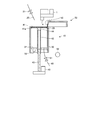
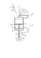
- FIG. 1 is a schematic view schematically showing a beverage extraction apparatus according to an embodiment of the present invention.
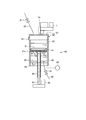
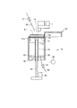
- FIG. 2 is an explanatory diagram showing a procedure of a beverage extraction operation of the beverage extraction device shown in FIG.
- FIG. 3 is an explanatory diagram showing a procedure of a beverage extraction operation of the beverage extraction device shown in FIG.
- FIG. 4 is an explanatory diagram showing the procedure of the beverage extraction operation of the beverage extraction device shown in FIG.
- FIG. 5 is an explanatory diagram showing a procedure of a beverage extraction operation of the beverage extraction device shown in FIG.
- FIG. 6 is an explanatory diagram showing the procedure of the beverage extraction operation of the beverage extraction device shown in FIG.
- FIG. 7 is an explanatory diagram showing the procedure of the beverage extraction operation of the beverage extraction device shown in FIG. FIG.
- FIG. 8 is an explanatory diagram showing the procedure of the beverage extraction operation of the beverage extraction device shown in FIG.
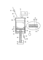
- FIG. 9 is an explanatory diagram showing a cleaning operation of the beverage extraction device shown in FIG.
- FIG. 10 is an explanatory view showing another example of the cleaning operation in the beverage extraction apparatus shown in FIG.
- FIG. 1 is a schematic view schematically showing a beverage extraction apparatus according to an embodiment of the present invention, and a part thereof is shown in cross section.
- the beverage extraction apparatus 10 illustrated here is applied to a beverage server that provides beverages such as coffee and tea, a cup-type beverage vending machine, and the like.
- the coffee beverage is extracted from the pulverized beans (beverage raw material) and the hot water supplied from the hot water supply path 20.
- the hot water supply path 20 is provided on the left side of the mill 1 and allows hot water supplied from a hot water tank (not shown) to pass therethrough.
- a hot water supply valve 21 is provided in the hot water supply path 20.
- the hot water supply valve 21 is a valve body that opens and closes in response to a command given from the control unit (control means) 80. In such a case, the hot water is restricted from passing through the hot water supply path 20.
- the beverage extraction apparatus 10 includes a cylinder 30, a piston unit 40, a cover member 50, an extraction path 60, and an ultrasonic vibrator 70.
- the cylinder 30 is entirely made of metal and has a bottomed cylindrical shape in which a lower surface opening 31 formed on the lower surface is closed by a bottom portion 32. Such a cylinder 30 is supported by a cylinder holder (not shown), and the axial direction coincides with the vertical direction.
- the piston unit 40 includes a mesh member 41, a feed nut 42, and a feed screw 43.
- the mesh member 41 is made of a metal material, for example, and has a disk shape.
- the mesh member 41 has a side surface that is in contact with the inner surface of the cylinder 30, and is formed such that a plurality of through holes 41 a penetrate vertically.
- the feed nut 42 is a long member whose vertical direction is the longitudinal direction, and is attached to the central portion of the lower surface of the mesh member 41 via a mounting block 44.
- the feed nut 42 has a cylindrical shape whose upper surface is closed by a mounting block 44, and passes through a nut hole 32 a formed in the central portion of the bottom 32.
- the outer diameter of the feed nut 42 is slightly smaller than the inner diameter of the nut hole portion 32a, and the gap between the feed nut 42 and the nut hole portion 32a is provided with a packing or the like to provide airtightness. Water tightness is ensured.
- the feed screw 43 is a long member whose longitudinal direction is the longitudinal direction, and a part of the feed screw 43 enters the feed nut 42.
- the feed screw 43 has an outer surface that enters the inside of the feed nut 42 and is screwed into an inner surface of the feed nut 42.
- a piston motor 45 is linked to the lower end of the feed screw 43. The piston motor 45 is driven to rotate forward and backward in accordance with a command given from the control unit 80.
- the feed screw 43 moves the feed nut 42 screwed downward by rotating clockwise around the center axis of the feed screw 43 as viewed from above, for example.
- the feed nut 42 is moved upward by rotating around the central axis, for example, counterclockwise as viewed from above.
- the mesh member 41 to which the feed nut 42 is attached via the attachment block 44 is in contact with the inner surface of the cylinder 30. It is possible to move in a state of approaching and moving away from the bottom 32 in the state.
- the cover member 50 is provided in the upper area of the cylinder 30.
- Such a cover member 50 has a box shape in which the lower wall portion is opened, and the upper wall portion 51 is large enough to cover the upper surface opening 33 of the cylinder 30.
- Such a cover member 50 is linked to the cover motor M.
- the cover motor M is driven to rotate forward and backward in accordance with a command given from the control unit 80.
- the cover member 50 moves to the right and moves to a fully open position where the upper surface opening 33 of the cylinder 30 is fully opened as indicated by a solid line in FIG.
- the cover motor M is driven in reverse rotation, it moves toward the left and moves to a fully closed position where the upper surface opening 33 of the cylinder 30 is fully closed as indicated by a broken line in FIG. .
- the cover member 50 is provided so as to be movable between a fully opened position where the upper surface opening 33 is fully closed and a fully opened position where the upper surface opening 33 is fully opened.
- the cover member 50 is also disposed at a midway position (third position) between the fully open position and the fully closed position and blocking a part of the upper surface opening 33.
- the cover member 50 has a scraper portion 52.
- the scraper portion 52 is attached to the left wall portion 53 of the cover member 50.
- the scraper portion 52 has a vertical dimension determined so that the lower end portion is in sliding contact with the upper surface of the cylinder 30 when the cover member 50 moves between the fully open position and the fully closed position.
- the extraction path 60 is connected to the bottom 32 in such a manner that it passes through an extraction hole (not shown) provided in the bottom 32.
- the extraction path 60 allows the coffee beverage extracted inside the cylinder 30 to pass through and be discharged to the beverage container C (see FIG. 8).
- the extraction path 60 is provided with an extraction valve 61 and a pressure sensor 62.
- the extraction valve 61 is a valve body that opens and closes in response to a command given from the control unit 80.
- the coffee beverage is allowed to pass through the extraction path 60, whereas when the extraction valve 61 is closed.
- the coffee beverage is restricted from passing through the extraction path 60.
- the pressure sensor 62 is provided on the upstream side of the extraction valve 61.
- the pressure sensor 62 detects the pressure below the mesh member 41 inside the cylinder 30.
- the pressure sensor 62 gives the detected pressure to the control unit 80 as a pressure signal.
- the ultrasonic vibrator 70 is attached to the bottom 32 of the cylinder 30.
- the ultrasonic vibrator 70 is driven in accordance with a command given from the control unit 80, and applies ultrasonic waves to the hot water stored in the cylinder 30 when driven.
- the mesh member 41 is disposed at the top dead center position at the same level as the upper surface of the cylinder 30 to close the upper surface opening 33, and the cover member 50 is fully opened. Placed in. Further, both the hot water supply valve 21 and the extraction valve 61 are closed.
- the control unit 80 gives a drive command to the piston motor 45 to drive the piston motor 45 to rotate forward.
- the mesh member 41 moves downward together with the feed nut 42 as the feed screw 43 rotates clockwise as viewed from above.
- the control unit 80 gives a drive stop command to the piston motor 45.
- the mesh member 41 is disposed at the bottom dead center position as shown in FIG.
- the control unit 80 gives a drive command to the cover motor M to drive the cover motor M in the reverse direction. Thereby, the cover member 50 moves toward the left from the fully open position.
- the control unit 80 gives a drive stop command to the cover motor M.
- the cover member 50 is disposed in the middle position as shown in FIG. In this case, the cover member 50 closes the supply port 1 a of the mill 1 with its upper wall portion 51.
- the control unit 80 After the cover member 50 is disposed at the midway position, the control unit 80 gives an open command to the hot water supply valve 21 to open the hot water supply valve 21. As a result, hot water from the hot water tank passes through the hot water supply path 20 and is introduced into the cylinder 30. When the opening time of the hot water supply valve 21 reaches a predetermined time, the control unit 80 gives a close command to the hot water supply valve 21 to cause the hot water supply valve 21 to close. Thereby, a predetermined amount of hot water is put into the cylinder 30.
- the control unit 80 gives a drive command to the cover motor M to drive the cover motor M in the reverse direction. Thereby, the cover member 50 moves toward the left from the midway position and reaches the fully closed position.
- control unit 80 causes the mesh member 41 to stand by at the bottom dead center position until a predetermined time has elapsed after giving a drive stop command to the piston motor 45.
- the coffee raw material after the coffee raw material and hot water are stirred is precipitated on the upper surface of the mesh member 41 to become a precipitate D.
- a fine powder raw material precipitates, and a coffee raw material (hereinafter also referred to as a powder raw material) D2 having a diameter larger than that of the fine powder raw material D1 is deposited on the fine powder raw material D1.
- the control unit 80 gives a drive command to the piston motor 45 to drive the piston motor 45 in the reverse direction.
- the mesh member 41 moves upward together with the feed nut 42 by rotating the feed screw 43 counterclockwise as viewed from above.
- the coffee raw material and hot water agitation liquid can pass through the through-hole 41 a and extract the coffee beverage below the mesh member 41. it can.
- the control unit 80 preferably performs PWM control of the piston motor 45 so that the pressure value (pressure result) given from the pressure sensor 62 becomes a predetermined pressure value set in advance.
- control unit 80 gives a drive command to the cover motor M to drive the cover motor M in the normal direction. Thereby, the cover member 50 moves toward the right from the fully closed position.
- control unit 80 gives a drive stop command to the cover motor M. As a result, the cover member 50 is disposed at the fully open position.
- the control unit 80 gives a drive command to the cover motor M to drive the cover motor M in the reverse direction.
- the cover member 50 moves toward the left from the fully open position.
- the scraper portion 52 of the cover member 50 is in sliding contact with the upper surface of the mesh member 41 at the top dead center position, so that the extraction basket K placed on the upper surface of the mesh member 41 is scraped off, as shown in FIG.
- the extracted soot K can be accommodated in the soot container B arranged on the left side of the cylinder 30. In this way, when the cover member 50 moves to the fully closed position, the control unit 80 gives a drive stop command to the cover motor M.
- control unit 80 gives an open command to the extraction valve 61 in parallel with the drive command to the cover motor M. Thereby, the extraction valve 61 is opened, and the coffee beverage stored in the cylinder 30 passes through the extraction path 60 and is discharged into the beverage container C.
- control unit 80 After discharging the coffee beverage in this way, the control unit 80 gives a close command to the extraction valve 61 and also gives a drive command to the cover motor M to drive the cover motor M in the normal direction. Thereby, the cover member 50 is arrange
- Such a cleaning operation is not performed every time a product is sold like the above-described extraction operation, but is performed by giving a cleaning command to the control unit 80 at a predetermined time or every predetermined time.
- the control unit 80 gives a drive command to the piston motor 45 to drive the piston motor 45 to rotate forward.
- the mesh member 41 moves downward together with the feed nut 42 as the feed screw 43 rotates clockwise as viewed from above.
- the control unit 80 gives a drive stop command to the piston motor 45.
- the mesh member 41 is disposed at an intermediate position as shown in FIG.
- control unit 80 gives a drive command to the cover motor M to drive the cover motor M in the reverse direction, and moves the cover member 50 from the fully open position to the midway position.
- the control unit 80 After the cover member 50 is disposed at the midway position, the control unit 80 gives an open command to the hot water supply valve 21 to open the hot water supply valve 21. As a result, hot water from the hot water tank passes through the hot water supply path 20 and is introduced into the cylinder 30. When the opening time of the hot water supply valve 21 reaches a predetermined time, the control unit 80 gives a close command to the hot water supply valve 21 to cause the hot water supply valve 21 to close. Thereby, a predetermined amount of hot water is put into the cylinder 30.
- the control unit 80 gives a drive command to the piston motor 45 to drive the piston motor 45 in the normal rotation and reverse rotation for a predetermined time.
- the mesh member 41 moves up and down for a predetermined time, and the air staying in the lower portion of the mesh member 41 is removed to the outside by adding hot water. By removing the air, it is possible to satisfactorily apply ultrasonic waves by the ultrasonic vibrator 70 described later.
- control unit 80 gives a drive command to the ultrasonic vibrator 70.
- the ultrasonic vibrator 70 is driven to apply ultrasonic waves to the hot water in the cylinder 30.
- control unit 80 gives a drive command to the piston motor 45 to drive the piston motor 45 in reverse and forward rotation.
- the mesh member 101 alternately moves up and down.
- the control unit 80 After driving the ultrasonic vibrator 70 and driving the piston motor 45 in reverse and forward for a predetermined time, the control unit 80 gives a drive stop command to the ultrasonic vibrator 70 and the piston motor 45. And the control part 80 gives an open command to the extraction valve 61, and discharges the hot water of the cylinder 30 outside. Thereafter, the control unit 80 gives commands to the piston motor 45, the cover motor M, and the extraction valve 61 to return to the standby state, and ends the current cleaning operation.
- the control unit 80 performs ultrasonic in a state where hot water is stored in the cylinder 30. Since the ultrasonic wave is applied to the hot water by driving the vibrator 70 and the mesh member 41 is moved up and down, the mesh member 41 and the inner surface of the cylinder 30 can be cleaned by the cavitation effect, and the mesh member 41 is removed. Cleaning can be performed satisfactorily without any problems.
- the mesh member 41 and the like can be washed well as described above, the quality of the extracted beverage can be maintained.
- the entire cylinder 30 is made of metal, the entire cylinder 30 is vibrated by driving the ultrasonic vibrator 70, and ultrasonic waves are applied over the entire area of the hot water in the cylinder 30.
- the cleaning effect can be improved.
- the mesh member 41 is moved up and down in the cleaning operation.
- the mesh member 41 is set in a predetermined cleaning position, that is, ultrasonic vibration.
- the cleaning operation may be performed at a position where the cavitation effect due to driving of the vessel 70 is maximized.
- the cleaning position is determined for each apparatus depending on the shape and size of the cylinder 30 and the location where the ultrasonic vibrator 70 is attached.
- the mesh member 41 is moved up and down in the cleaning operation.
- the mesh member may be further rotated around the axis.
- the entire cylinder 30 is made of metal, but in the present invention, the cylinder may be made of metal only at the bottom where the ultrasonic vibrator is provided.
Landscapes
- Engineering & Computer Science (AREA)
- Food Science & Technology (AREA)
- Apparatus For Making Beverages (AREA)
Abstract
Description
20 給湯経路
30 シリンダ
31 下面開口
32 底部
33 上面開口
40 ピストンユニット
41 メッシュ部材
50 カバー部材
60 抽出経路
70 超音波振動器
80 制御部
Claims (3)
- 下面開口が金属製の底部により閉塞された有底円筒状のシリンダと、
複数の貫通孔が形成された円板状を成し、側面が前記シリンダの内面に接した状態で前記底部に近接離反する態様で移動可能なメッシュ部材と
を備え、
前記シリンダの上面開口を通じて投入された飲料原料と湯とから前記メッシュ部材の移動により飲料を抽出し、抽出した飲料を前記底部に接続された抽出経路を通じて吐出する飲料抽出装置であって、
前記底部に設けられた超音波振動器と、
洗浄指令が与えられた場合に、前記シリンダの内部に湯を貯留させた状態で前記超音波振動器を駆動させることにより前記湯に超音波を付与し、かつ前記メッシュ部材を前記底部に近接離反する態様で移動させる制御手段と
を備えたことを特徴とする飲料抽出装置。 - 下面開口が金属製の底部により閉塞された有底円筒状のシリンダと、
複数の貫通孔が形成された円板状を成し、側面が前記シリンダの内面に接した状態で前記底部に近接離反する態様で移動可能なメッシュ部材と
を備え、
前記シリンダの上面開口を通じて投入された飲料原料と湯とから前記メッシュ部材の移動により飲料を抽出し、抽出した飲料を前記底部に接続された抽出経路を通じて吐出する飲料抽出装置であって、
前記底部に設けられた超音波振動器と、
洗浄指令が与えられた場合に、前記シリンダの内部に湯を貯留させた状態で前記メッシュ部材を前記底部から所定距離だけ離隔した予め設定された洗浄位置に配置させ、かつ前記超音波振動器を駆動させて前記湯に超音波を付与する制御手段と
を備えたことを特徴とする飲料抽出装置。 - 前記シリンダの全体が金属製であることを特徴とする請求項1又は請求項2に記載の飲料抽出装置。
Priority Applications (4)
| Application Number | Priority Date | Filing Date | Title |
|---|---|---|---|
| KR1020197006184A KR102212235B1 (ko) | 2016-09-01 | 2017-07-03 | 음료 추출 장치 |
| JP2018536984A JP6860014B2 (ja) | 2016-09-01 | 2017-07-03 | 飲料抽出装置 |
| CN201780053366.7A CN109688883A (zh) | 2016-09-01 | 2017-07-03 | 饮料提取装置 |
| US16/284,521 US11219332B2 (en) | 2016-09-01 | 2019-02-25 | Beverage extraction device |
Applications Claiming Priority (2)
| Application Number | Priority Date | Filing Date | Title |
|---|---|---|---|
| JP2016-170908 | 2016-09-01 | ||
| JP2016170908 | 2016-09-01 |
Related Child Applications (1)
| Application Number | Title | Priority Date | Filing Date |
|---|---|---|---|
| US16/284,521 Continuation US11219332B2 (en) | 2016-09-01 | 2019-02-25 | Beverage extraction device |
Publications (1)
| Publication Number | Publication Date |
|---|---|
| WO2018042863A1 true WO2018042863A1 (ja) | 2018-03-08 |
Family
ID=61305318
Family Applications (1)
| Application Number | Title | Priority Date | Filing Date |
|---|---|---|---|
| PCT/JP2017/024306 Ceased WO2018042863A1 (ja) | 2016-09-01 | 2017-07-03 | 飲料抽出装置 |
Country Status (5)
| Country | Link |
|---|---|
| US (1) | US11219332B2 (ja) |
| JP (1) | JP6860014B2 (ja) |
| KR (1) | KR102212235B1 (ja) |
| CN (1) | CN109688883A (ja) |
| WO (1) | WO2018042863A1 (ja) |
Cited By (2)
| Publication number | Priority date | Publication date | Assignee | Title |
|---|---|---|---|---|
| CN112839550A (zh) * | 2018-12-04 | 2021-05-25 | 富士电机株式会社 | 饮料供给装置 |
| KR102927185B1 (ko) | 2024-11-05 | 2026-02-23 | 김묘웅 | 급속으로 대용량의 콜드브루 커피를 추출하는 장치 |
Families Citing this family (1)
| Publication number | Priority date | Publication date | Assignee | Title |
|---|---|---|---|---|
| EP4306017A4 (en) * | 2021-03-11 | 2024-08-14 | New Innovations Inc. | BEVERAGE PRODUCTION DEVICE |
Citations (3)
| Publication number | Priority date | Publication date | Assignee | Title |
|---|---|---|---|---|
| JP2006007104A (ja) * | 2004-06-25 | 2006-01-12 | Shimada Phys & Chem Ind Co Ltd | 超音波洗浄装置 |
| JP2014502751A (ja) * | 2010-12-16 | 2014-02-03 | ブリゴ・リミテッド・ライアビリティ・カンパニー | 淹出およびエスプレッソドリンク生成のための装置および方法 |
| US20140170280A1 (en) * | 2012-12-14 | 2014-06-19 | Vki Technologies Inc. | System and method for making a beverage |
Family Cites Families (17)
| Publication number | Priority date | Publication date | Assignee | Title |
|---|---|---|---|---|
| JPS5044558Y2 (ja) | 1971-02-21 | 1975-12-18 | ||
| US3824913A (en) * | 1973-04-16 | 1974-07-23 | Coffee Mat Corp | Apparatus for cleaning brew head screen |
| MX2008003736A (es) | 2005-04-11 | 2009-01-29 | Starbucks Corp | Maquina para preparar una bebida, tal como el cafe, y metodo relacionado. |
| WO2007027206A2 (en) | 2005-04-11 | 2007-03-08 | Coffee Equipment Company | Machine for brewing a beverage such as coffee and related method |
| US20080032030A1 (en) * | 2006-08-15 | 2008-02-07 | Eilaz Babaev | Method and Apparatus for Producing Beverages from Coffee Beans Using Ultrasound Energy |
| US20080202346A1 (en) * | 2007-02-16 | 2008-08-28 | Mario Bernardo Accumanno | Tea maker with agitator |
| DE102007017450A1 (de) * | 2007-04-02 | 2008-10-09 | Niro-Plan Ag | Verfahren und Vorrichtung zur Herstellung von Caffe Latte Macchiato |
| US7980168B2 (en) * | 2007-06-26 | 2011-07-19 | Maurer Scott D | Hot beverage maker with filter deforming member |
| US20100272870A1 (en) * | 2009-04-24 | 2010-10-28 | Far East University | Preparation method for caffeine control and device thereof |
| CN201579016U (zh) * | 2009-09-29 | 2010-09-15 | 吴银隆 | 带超声波清洗功能的搅拌机 |
| JP2013514831A (ja) * | 2009-12-18 | 2013-05-02 | グリーン マウンテン コーヒー ロースターズ,インク. | 音波エネルギーを使用した飲料形成装置及び方法 |
| US20110297004A1 (en) * | 2010-06-03 | 2011-12-08 | Mark Figura | Ultrasonic brew technology systems |
| CN201898195U (zh) * | 2010-11-16 | 2011-07-13 | 上海金东线缆设备有限公司 | 一种超声波清洗定径装置 |
| KR102101298B1 (ko) * | 2011-11-23 | 2020-04-16 | 스타벅스 코포레이션 | 음료를 브루잉하기 위한 장치, 시스템 및 방법 |
| CN202801287U (zh) * | 2012-07-05 | 2013-03-20 | 苏州工业园区咖乐美电器有限公司 | 一种具有超声波清洗功能的咖啡机 |
| EP2881021A1 (de) * | 2013-12-06 | 2015-06-10 | Jura Elektroapparate Ag | Getränkebereitungsmaschine und Verfahren zum Betreiben einer Getränkebereitungsmaschine |
| KR101630262B1 (ko) * | 2015-07-13 | 2016-06-14 | 이상준 | 음파 진동을 이용한 콜드 브루 커피 추출 장치 |
-
2017
- 2017-07-03 JP JP2018536984A patent/JP6860014B2/ja active Active
- 2017-07-03 KR KR1020197006184A patent/KR102212235B1/ko active Active
- 2017-07-03 CN CN201780053366.7A patent/CN109688883A/zh active Pending
- 2017-07-03 WO PCT/JP2017/024306 patent/WO2018042863A1/ja not_active Ceased
-
2019
- 2019-02-25 US US16/284,521 patent/US11219332B2/en active Active
Patent Citations (3)
| Publication number | Priority date | Publication date | Assignee | Title |
|---|---|---|---|---|
| JP2006007104A (ja) * | 2004-06-25 | 2006-01-12 | Shimada Phys & Chem Ind Co Ltd | 超音波洗浄装置 |
| JP2014502751A (ja) * | 2010-12-16 | 2014-02-03 | ブリゴ・リミテッド・ライアビリティ・カンパニー | 淹出およびエスプレッソドリンク生成のための装置および方法 |
| US20140170280A1 (en) * | 2012-12-14 | 2014-06-19 | Vki Technologies Inc. | System and method for making a beverage |
Cited By (3)
| Publication number | Priority date | Publication date | Assignee | Title |
|---|---|---|---|---|
| CN112839550A (zh) * | 2018-12-04 | 2021-05-25 | 富士电机株式会社 | 饮料供给装置 |
| CN112839550B (zh) * | 2018-12-04 | 2023-11-03 | 富士电机株式会社 | 饮料供给装置 |
| KR102927185B1 (ko) | 2024-11-05 | 2026-02-23 | 김묘웅 | 급속으로 대용량의 콜드브루 커피를 추출하는 장치 |
Also Published As
| Publication number | Publication date |
|---|---|
| CN109688883A (zh) | 2019-04-26 |
| KR102212235B1 (ko) | 2021-02-04 |
| JPWO2018042863A1 (ja) | 2019-06-24 |
| KR20190037292A (ko) | 2019-04-05 |
| JP6860014B2 (ja) | 2021-04-14 |
| US11219332B2 (en) | 2022-01-11 |
| US20190183284A1 (en) | 2019-06-20 |
Similar Documents
| Publication | Publication Date | Title |
|---|---|---|
| CN101217904B (zh) | 用于制备咖啡的装置 | |
| WO2018042863A1 (ja) | 飲料抽出装置 | |
| JP5863557B2 (ja) | 超音波洗浄装置 | |
| JP2006524076A (ja) | 飲料抽出装置 | |
| KR101669435B1 (ko) | 여과장치 | |
| JP6852280B2 (ja) | 飲料抽出方法 | |
| JP2731186B2 (ja) | 飲料抽出器 | |
| KR20160121202A (ko) | 커피 드립 장치 | |
| KR101634932B1 (ko) | 유체 여과장치 | |
| KR102231060B1 (ko) | 음료 추출 장치 | |
| NL1007063C2 (nl) | Vloeistofreinigingsinrichting. | |
| JP2017202044A (ja) | 飲料抽出装置 | |
| JP2008113972A (ja) | コーヒー抽出機 | |
| JP6816599B2 (ja) | 飲料抽出装置 | |
| EP3463701B1 (en) | Dosing apparatus for powder products | |
| JP6866735B2 (ja) | 飲料抽出装置 | |
| KR101229797B1 (ko) | 정수기능 및 캐비테이션 토출 기능을 구비한 수전금구 | |
| JP2611929B2 (ja) | 抽出槽装置 | |
| WO2018116736A1 (ja) | 飲料抽出装置 | |
| JP2007222254A (ja) | 飲料抽出装置及び抽出残渣の除去方法 | |
| US435971A (en) | Sirup-filter | |
| JP3088913B2 (ja) | 洗米装置 | |
| KR20120124926A (ko) | 저온저압 식음료 제조장치 | |
| CN210474097U (zh) | 一种化学安全研磨装置 | |
| JPH0263007B2 (ja) |
Legal Events
| Date | Code | Title | Description |
|---|---|---|---|
| 121 | Ep: the epo has been informed by wipo that ep was designated in this application |
Ref document number: 17845873 Country of ref document: EP Kind code of ref document: A1 |
|
| ENP | Entry into the national phase |
Ref document number: 2018536984 Country of ref document: JP Kind code of ref document: A |
|
| ENP | Entry into the national phase |
Ref document number: 20197006184 Country of ref document: KR Kind code of ref document: A |
|
| NENP | Non-entry into the national phase |
Ref country code: DE |
|
| 122 | Ep: pct application non-entry in european phase |
Ref document number: 17845873 Country of ref document: EP Kind code of ref document: A1 |