WO2018037633A1 - 撮像制御装置、撮像装置および撮像制御方法 - Google Patents
撮像制御装置、撮像装置および撮像制御方法 Download PDFInfo
- Publication number
- WO2018037633A1 WO2018037633A1 PCT/JP2017/017828 JP2017017828W WO2018037633A1 WO 2018037633 A1 WO2018037633 A1 WO 2018037633A1 JP 2017017828 W JP2017017828 W JP 2017017828W WO 2018037633 A1 WO2018037633 A1 WO 2018037633A1
- Authority
- WO
- WIPO (PCT)
- Prior art keywords
- image signal
- interest
- region
- attention area
- imaging
- Prior art date
- Legal status (The legal status is an assumption and is not a legal conclusion. Google has not performed a legal analysis and makes no representation as to the accuracy of the status listed.)
- Ceased
Links
Images







Classifications
-
- G—PHYSICS
- G03—PHOTOGRAPHY; CINEMATOGRAPHY; ANALOGOUS TECHNIQUES USING WAVES OTHER THAN OPTICAL WAVES; ELECTROGRAPHY; HOLOGRAPHY
- G03B—APPARATUS OR ARRANGEMENTS FOR TAKING PHOTOGRAPHS OR FOR PROJECTING OR VIEWING THEM; APPARATUS OR ARRANGEMENTS EMPLOYING ANALOGOUS TECHNIQUES USING WAVES OTHER THAN OPTICAL WAVES; ACCESSORIES THEREFOR
- G03B15/00—Special procedures for taking photographs; Apparatus therefor
-
- G—PHYSICS
- G03—PHOTOGRAPHY; CINEMATOGRAPHY; ANALOGOUS TECHNIQUES USING WAVES OTHER THAN OPTICAL WAVES; ELECTROGRAPHY; HOLOGRAPHY
- G03B—APPARATUS OR ARRANGEMENTS FOR TAKING PHOTOGRAPHS OR FOR PROJECTING OR VIEWING THEM; APPARATUS OR ARRANGEMENTS EMPLOYING ANALOGOUS TECHNIQUES USING WAVES OTHER THAN OPTICAL WAVES; ACCESSORIES THEREFOR
- G03B37/00—Panoramic or wide-screen photography; Photographing extended surfaces, e.g. for surveying; Photographing internal surfaces, e.g. of pipe
-
- G—PHYSICS
- G06—COMPUTING OR CALCULATING; COUNTING
- G06T—IMAGE DATA PROCESSING OR GENERATION, IN GENERAL
- G06T5/00—Image enhancement or restoration
- G06T5/80—Geometric correction
-
- G—PHYSICS
- G06—COMPUTING OR CALCULATING; COUNTING
- G06V—IMAGE OR VIDEO RECOGNITION OR UNDERSTANDING
- G06V10/00—Arrangements for image or video recognition or understanding
- G06V10/20—Image preprocessing
- G06V10/25—Determination of region of interest [ROI] or a volume of interest [VOI]
-
- G—PHYSICS
- G06—COMPUTING OR CALCULATING; COUNTING
- G06V—IMAGE OR VIDEO RECOGNITION OR UNDERSTANDING
- G06V40/00—Recognition of biometric, human-related or animal-related patterns in image or video data
- G06V40/10—Human or animal bodies, e.g. vehicle occupants or pedestrians; Body parts, e.g. hands
- G06V40/16—Human faces, e.g. facial parts, sketches or expressions
- G06V40/161—Detection; Localisation; Normalisation
-
- G—PHYSICS
- G06—COMPUTING OR CALCULATING; COUNTING
- G06V—IMAGE OR VIDEO RECOGNITION OR UNDERSTANDING
- G06V40/00—Recognition of biometric, human-related or animal-related patterns in image or video data
- G06V40/10—Human or animal bodies, e.g. vehicle occupants or pedestrians; Body parts, e.g. hands
- G06V40/16—Human faces, e.g. facial parts, sketches or expressions
- G06V40/161—Detection; Localisation; Normalisation
- G06V40/165—Detection; Localisation; Normalisation using facial parts and geometric relationships
-
- H—ELECTRICITY
- H04—ELECTRIC COMMUNICATION TECHNIQUE
- H04N—PICTORIAL COMMUNICATION, e.g. TELEVISION
- H04N23/00—Cameras or camera modules comprising electronic image sensors; Control thereof
- H04N23/60—Control of cameras or camera modules
- H04N23/61—Control of cameras or camera modules based on recognised objects
- H04N23/611—Control of cameras or camera modules based on recognised objects where the recognised objects include parts of the human body
-
- H—ELECTRICITY
- H04—ELECTRIC COMMUNICATION TECHNIQUE
- H04N—PICTORIAL COMMUNICATION, e.g. TELEVISION
- H04N23/00—Cameras or camera modules comprising electronic image sensors; Control thereof
- H04N23/60—Control of cameras or camera modules
- H04N23/63—Control of cameras or camera modules by using electronic viewfinders
- H04N23/633—Control of cameras or camera modules by using electronic viewfinders for displaying additional information relating to control or operation of the camera
- H04N23/635—Region indicators; Field of view indicators
-
- H—ELECTRICITY
- H04—ELECTRIC COMMUNICATION TECHNIQUE
- H04N—PICTORIAL COMMUNICATION, e.g. TELEVISION
- H04N23/00—Cameras or camera modules comprising electronic image sensors; Control thereof
- H04N23/60—Control of cameras or camera modules
- H04N23/698—Control of cameras or camera modules for achieving an enlarged field of view, e.g. panoramic image capture
-
- H—ELECTRICITY
- H04—ELECTRIC COMMUNICATION TECHNIQUE
- H04N—PICTORIAL COMMUNICATION, e.g. TELEVISION
- H04N25/00—Circuitry of solid-state image sensors [SSIS]; Control thereof
- H04N25/40—Extracting pixel data from image sensors by controlling scanning circuits, e.g. by modifying the number of pixels sampled or to be sampled
- H04N25/44—Extracting pixel data from image sensors by controlling scanning circuits, e.g. by modifying the number of pixels sampled or to be sampled by partially reading an SSIS array
Definitions
- the present technology relates to an imaging control device, an imaging device, and an imaging control method.
- the present invention relates to an imaging control apparatus, an imaging apparatus, and an imaging control method that output an image signal in a partial area of the imaging area.
- an imaging device that has a wide-angle lens such as a fisheye lens and captures a wide viewing angle image has been used.
- an imaging apparatus has been proposed that improves the convenience by simultaneously displaying the person to be imaged and the object or other person that the person is paying attention to.
- a system has been proposed in which a gaze direction of a person to be imaged is predicted, a related object that the person is interested in is estimated from the gaze direction, and displayed simultaneously with the person (for example, see Patent Document 1).
- the above-described prior art acquires image signals of a person and related objects from the captured wide viewing angle image signal, displays the person, and forms a sub-screen in the display screen. Is displayed. For this reason, in the above-described conventional technology, a lot of processing is required for screen display, and there is a problem that power consumption increases.
- the present technology has been created in view of such a situation, and an object thereof is to reduce power consumption of an imaging apparatus that outputs an image signal in a partial area of the imaging area.
- a first aspect of the present technology is a region of interest that is a region that is attracting attention by a specific organism included in an image signal output from an image sensor.
- a region of interest detection unit for detecting the image signal from the image signal, and the output of the image signal in the detected region of interest from the image sensor to control the image signal in the non-region of interest other than the region of interest An imaging control apparatus and an imaging control method including an image signal control unit that performs control different from the region of interest. This brings about the effect that control of an image signal different from the attention area is performed on the non-attention area.
- the image signal control unit may perform control to stop the output of the image signal from the imaging element in the non-attention area.
- the image signal of the non-attention area brings about the effect that the output from the image sensor is stopped.
- the image signal control unit may perform control to output the image signal of the non-target region based on a resolution different from that of the target region.
- an image signal of a non-attention area having a resolution different from that of the attention area is output.
- the image signal control unit may perform control to output the image signal of the non-attention area based on a frame rate different from that of the attention area. As a result, an image signal of a non-attention area having a frame rate different from that of the attention area is output.
- the image processing apparatus may further include a distortion correction unit that corrects distortion of the image signal in the output attention area. This brings about the effect that the distortion of the image signal in the region of interest is corrected.
- the image sensor may output an image signal captured through a fisheye lens
- the distortion correction unit may correct image signal distortion caused by the fisheye lens.
- the attention area detection unit may detect the attention area based on face information which is face information of the specific living thing. This brings about the effect that the attention area is detected based on the face information.
- the attention area detection unit may detect the attention area based on a pointing direction of the specific living thing. This brings about the effect that the attention area is detected based on the pointing direction.
- the attention area detection unit selects the specific organism from the image signal output from the imaging device, and detects the attention area based on the selected specific organism. Also good. This brings about the effect that a specific organism is selected.
- the attention area detection unit may select a photographer as the specific organism. This brings about the effect that the photographer is selected as a specific person.
- the attention area detection unit selects one of the plurality of organisms as the specific organism when the image signal output from the imaging device includes a plurality of organisms. May be. This brings about the effect that one of a plurality of organisms is selected.
- the attention area detection unit may change the frequency of detecting the attention area. This brings about the effect that the detection frequency of the attention area is changed.
- the specific organism may be a specific person. This brings about the effect that a region that a specific person is interested in is detected as a region of interest.
- the second aspect of the present technology provides an attention area detection that detects an attention area, which is an area of interest from a specific organism included in an image signal output from the imaging element and the image sensor, from the image signal. And the output of the image signal in the detected region of interest from the image sensor, and control different from the region of interest for the image signal in the non-region of interest other than the region of interest And an image signal control unit. This brings about the effect that control of an image signal different from the attention area is performed on the non-attention area.
- the present technology it is possible to achieve an excellent effect of reducing the power consumption of the imaging device that outputs an image signal in a partial region of the imaging region.
- the effects described here are not necessarily limited, and may be any of the effects described in the present disclosure.
- FIG. 1 is a diagram illustrating a configuration example of an imaging device 10 according to an embodiment of the present technology.
- the imaging apparatus 10 includes a fisheye lens 100, an imaging element 200, an imaging control unit 300, and a storage 400.
- the fisheye lens 100 forms an image on the image sensor 200.
- the fish-eye lens 100 is a projection type lens that is not a central projection type, and is a lens that forms an image with a wide viewing angle.
- the image sensor 200 captures an image formed by the fisheye lens 100. Since imaging is performed via the fisheye lens 100, the captured image is a wide viewing angle image.
- the imaging element 200 is controlled by the imaging control unit 300, performs imaging and processing of the image signal after imaging, and outputs the processed image signal.
- analog-digital conversion for converting an analog image signal into a digital image signal can be performed.
- the processing of the image signal can be performed on either a frame that is an image signal for one screen or an image signal of a selected region. For example, a region of interest described later corresponds to this selected region.
- the imaging control unit 300 controls the imaging element 200.
- the imaging control unit 300 controls imaging and image signal processing in the imaging element 200. Specifically, the imaging control unit 300 performs control to cause the imaging element 200 to output an image signal of the region of interest.
- the attention area is an area that is attracted by a specific person included in the frame, and is an area that is a target of image processing, storage, and the like in the imaging apparatus 10.
- the specific person is a person who uses the imaging device 10. For example, a photographer corresponds to the specific person.
- the imaging control unit 300 performs image processing such as distortion correction on the image signal of the region of interest and outputs the processed image signal to the storage 400.
- the attention area can be detected, for example, from the image signal of the photographer's face area included in the frame output from the image sensor 200.
- the imaging control unit 300 performs control different from that of the attention area for the image signal of the non-attention area that is an area other than the attention area. Note that details of control of image signals in the attention area and non-attention area and details of the configuration of the imaging control unit 300 will be described later. Further, imaging information described later is output from the imaging control unit 300 via the signal line 11.
- the storage 400 holds the image signal of the region of interest output from the imaging control unit 300.
- an image signal output from the imaging control unit 300 can be supplied to the outside of the imaging apparatus 10 through a signal line.
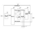
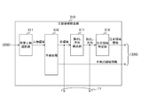
- FIG. 2 is a diagram illustrating a configuration example of the imaging control unit 300 according to the first embodiment of the present technology.
- the imaging control unit 300 includes an attention area detection unit 310, an image signal control unit 320, and a distortion correction unit 330.
- the attention area detection unit 310 detects the attention area.
- the attention area detection unit 310 generates attention area information indicating the position of the detected attention area and outputs the attention area information to the image signal control unit 320.
- the attention area information can be generated as follows, for example. First, an area of a photographer who is a specific person is detected from a frame output from the image sensor 200. Next, the area of the photographer's face is detected from the area of the photographer. Next, an attention area is detected from the area of the photographer's face, and information on the position of the area is generated as attention area information. Further, the attention area detection unit 310 generates position information of the detected photographer's face area as face detection area information, and further outputs it to the image signal control unit 320.
- the attention area detection unit 310 can output the imaging information generated in the process of detecting the attention area to the outside of the imaging apparatus 10.
- line-of-sight information, face orientation, and attention area information are output as imaging information via the signal line 11.
- the imaging information is not limited to this example.
- any one of line-of-sight information, face orientation, and attention area information can be output as imaging information. Details of the configuration of the attention area detection unit 310 will be described later.
- the image signal control unit 320 controls the image sensor 200 to output an image signal of a region of interest.
- the image signal control unit 320 controls the image sensor 200 based on the attention area information output from the attention area detection unit 310 and outputs an image signal of the attention area. This can be performed, for example, by calculating a readout window based on the attention area information and inputting it to the image sensor 200.
- the image signal control unit 320 performs control different from the above-described image signal of the attention area on the image signal of the non-attention area.
- the image signal control unit 320 can control the imaging element 200 to stop outputting the image signal of the non-target region.
- the analog-digital conversion processing of the image signal of the non-attention area other than the face detection area in the image sensor 200 can be omitted.
- the power consumption of the imaging device 10 can be reduced.
- only the image signal of the attention area is held in the storage 400, and the capacity of the storage 400 can be reduced.
- the image signal control unit 320 can set the image signal of the non-attention area to a resolution different from that of the attention area, for example, a resolution lower than the attention area. This can be performed, for example, by thinning out lines for outputting image signals in the non-attention area. Further, the image signal control unit 320 can output the image signal of the non-target region based on a frame rate different from that of the target region, for example, a low frame rate. As a result, the power consumption of the image sensor 200 can be reduced.
- the image signal control unit 320 further controls output of the image signal in the face detection area based on the face detection area information output from the attention area detection unit 310.
- the output of the image signal in the face detection area is performed to detect the attention area, and is controlled separately from the above-described image signal in the non-attention area.
- the image signals of the attention area and the face detection area can be output from the image sensor 200, and the output of the image signals of other non-attention areas can be stopped. If there is no problem in detecting the attention area, the resolution and the frame rate of the face detection area can be changed to a low value.
- the distortion correction unit 330 corrects distortion of the image signal in the region of interest.
- the distortion correction unit 330 can select an image signal in a region of interest from image signals output from the image sensor 200 and correct distortion.
- the selection of the image signal of the attention area can be performed, for example, by selecting the image signal included in the readout window based on the attention area information output from the attention area detection unit 310. Thereby, the correction of the image signal of the non-attention area can be omitted, and the power consumption of the imaging device 10 can be further reduced.
- a known method can be used to correct the distortion.
- the distortion correction unit 330 can perform fisheye distortion correction that corrects distortion caused by the fisheye lens 100.
- the corrected image signal of the attention area is output to the storage 400.
- imaging control unit 300 is an example of an imaging control device described in the claims.
- FIG. 3 is a diagram illustrating a configuration example of the attention area detection unit 310 according to the first embodiment of the present technology.
- the attention area detection section 310 includes a specific person selection section 311, a face detection section 312, a face direction detection section 313, a line-of-sight detection section 314, and an attention area identification section 315.
- the specific person selection unit 311 selects a specific person included in the image signal output from the image sensor 200.
- the specific person selection unit 311 outputs the selected specific person region to the face detection unit 312.
- the specific person selection unit 311 can select a photographer and output the area, for example.
- the specific person selection unit 311 can output an image signal of the corresponding area. For example, when the photographer wears the imaging device 10 and performs imaging, the photographer is included in the upper end portion of the screen. In such a case, a fixed area such as the upper end of the screen can be output.
- the face detection unit 312 detects a face area from the person area output from the specific person selection unit 311.
- a known method for example, a pattern matching method can be used to detect the face area.
- the face detection unit 312 outputs the detected face area image signal to the face direction detection unit 313 and the line-of-sight detection unit 314. Further, the face detection unit 312 detects the position of the region in the frame from the detected image signal of the face region, and outputs it to the image signal control unit 320 as face detection region information.
- the face direction detection unit 313 detects the face direction from the image signal of the face area output from the face detection unit 312.
- the face direction detection unit 313 outputs the detected face direction to the attention area specifying unit 315.
- the face orientation detection unit 313 outputs the detected face orientation to the outside of the imaging apparatus 10 via the signal line 11.
- a known method can be used to detect the face orientation.
- the face direction can be detected by detecting the direction of the nose.
- the orientation of the face can be detected by detecting the orientation of the jaw.
- the line-of-sight detection unit 314 detects the line of sight from the image signal of the face area output from the face detection unit 312.
- the line-of-sight detection unit 314 outputs the detected line-of-sight information to the attention area specifying unit 315 as line-of-sight information.
- the line-of-sight detection unit 314 outputs line-of-sight information to the outside of the imaging device 10 via the signal line 11.
- a known method can be used to detect the line of sight. For example, the line of sight of a person can be detected from the distance between the head of the eye and the center of the black eye.
- the attention area specifying unit 315 specifies the attention area.
- the attention area specifying unit 315 specifies the attention area from either one or both of the face direction output from the face direction detection unit 313 and the line-of-sight information output from the line-of-sight detection unit 314.
- the attention area specifying unit 315 detects the position of the area in the frame from the specified attention area, and outputs it to the image signal control unit 320 as attention area information. Further, the attention area specifying unit 315 outputs attention area information to the outside of the imaging apparatus 10 via the signal line 11.
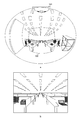
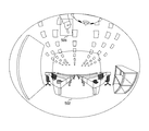
- FIG. 4 is a diagram illustrating an example of a region of interest in the first embodiment of the present technology.
- the figure shows an example in which a photographer takes an image while wearing the imaging device 10. For this reason, the photographer's face is shown at the top of the screen.
- “a” represents the entire image (frame) imaged by the image sensor 200. Since the image is taken through the fisheye lens 100, the image has a wide viewing angle.
- areas a 501 and 502 a represent the face area and the attention area of the photographer, respectively.
- the specific person selection unit 311 can output the area at the upper end of the screen as a person area.
- the size of the attention area 502 can be set to a predetermined size. In this way, the photographer turns his face or line of sight to the area of interest. Therefore, the attention area can be detected by detecting the orientation of the face.
- FIG. 5 is a diagram illustrating an example of imaging control according to the first embodiment of the present technology.
- the figure shows the control operation of the image sensor 200 in the image signal control unit 320.
- the image signal control unit 320 initializes the image sensor 200 (601). This initialization corresponds to, for example, an imaging mode setting process for the imaging device 200.
- the image signal control unit 320 performs control for the sensing operation (602).
- This sensing operation [0] is an operation for detecting a region of interest from the image signal output from the image sensor 200.
- a face area is detected from the image signal output from the image sensor 200, and the attention area is detected from the detected face area.
- the detection of the face area and the attention area is performed by the attention area detection unit 310.
- the image signal control unit 320 performs control for the viewing operation (603) in addition to the sensing operation.
- This viewing operation is an operation of reading an image signal of a region of interest from the image sensor 200.
- This viewing operation is performed simultaneously with the sensing operation. In other words, two areas of the face detection area and the attention area are simultaneously output from the image sensor 200. Note that the attention area detected in the previous sensing operation is applied to the attention area to be read in the viewing operation.
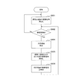
- FIG. 6 is a diagram illustrating an example of a processing procedure of imaging control processing according to the first embodiment of the present technology.
- the process in the figure represents the process when the face detection area is fixed as described in FIG.
- the imaging control unit 300 reads an image signal of the face detection area (step S901).
- the imaging control unit 300 detects a face area from the read image signal of the face detection area (step S902).
- step S902 No
- the imaging control unit 300 executes the process of step S901 again.
- step S902 When the face area is detected in step S902 (step S902: Yes), the imaging control unit 300 detects the attention area based on the face area (step S904). Next, the imaging control unit 300 reads out image signals of the face detection area and the attention area (step S905). Next, the imaging control unit 300 performs distortion correction of the image signal of the attention area (step S906). The image signal whose distortion has been corrected is held in the storage 400. Thereafter, the imaging control unit 300 executes the processing from step S902 again.
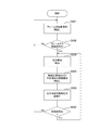
- FIG. 7 is a diagram illustrating another example of the processing procedure of the imaging control process according to the first embodiment of the present technology. This figure shows the processing when the face detection area is not fixed.
- the imaging control unit 300 reads out an image signal of a frame from the imaging device 200 (step S921).
- the imaging control unit 300 detects a face area from the read image signal of the frame (step S928). If the face area cannot be detected (step S928: No), the imaging control unit 300 executes the process of step S921 again.
- step S928 Yes
- the imaging control unit 300 detects the attention area (step S924).
- the imaging control unit 300 reads the image signals of the face detection area and the attention area (step S925), and corrects the distortion of the image signal of the attention area (step S926).
- the imaging control unit 300 detects a face area from the read face detection area (step S922).
- step S922 No
- the imaging control unit 300 executes the processing from step S921 again.
- step S922: Yes the imaging control unit 300 executes the processing from step S924 again.
- the attention area detection unit 310 detects the attention area, so that only the image signal of the attention area is output from the image sensor, and the image of the non-attention area is displayed.
- the signal output can be omitted. Thereby, the power consumption in the imaging device 10 can be reduced.
- Second Embodiment> the photographer is selected as a specific person on the assumption that the photographer wears the imaging device 10 and performs photographing. On the other hand, the photographer may install the imaging device 10 at a distant position and take an image including a plurality of persons.
- the second embodiment of the present technology is different from the above-described first embodiment in that a specific person is selected when the photographer is not clear.
- FIG. 8 is a diagram illustrating an example of a region of interest in the second embodiment of the present technology.
- the figure shows an example of an image captured by the imaging device 10 installed at a position away from the photographer.
- An area 503 represents an area of a specific person.
- the specific person is selected by the specific person selection unit 311 described with reference to FIG.
- the specific person selecting unit 311 selects one of the plurality of persons. A person can be selected and the area of the person can be output.
- the specific person selection unit 311 can select a person designated by a photographer or the like as a specific person.
- the person can be specified by, for example, arranging a user interface that receives an operation input by the user in the imaging apparatus 10 and specifying the user interface via the user interface.
- the face detection area 504 and the attention area 505 are sequentially detected from the specific person area 503.
- FIG. 9 is a diagram illustrating an example of a processing procedure of imaging control processing according to the second embodiment of the present technology.
- the imaging control unit 300 reads out an image signal of a frame from the imaging element 200 (step S941).
- the imaging control unit 300 selects a specific person from the read image signal of the frame (step S948).
- the imaging control unit 300 executes the process of step S941 again.
- the imaging control unit 300 detects a face area from the image signal of the specific person (step S947).
- the imaging control unit 300 executes the processing from step S941 again.
- step S947 when the face area is detected (step S947: Yes), the imaging control unit 300 detects the attention area based on the face area (step S944). Next, the imaging control unit 300 reads the image signals of the face detection area and the attention area (step S945), and corrects the distortion of the image signal of the attention area (step S946). Next, the imaging control unit 300 detects a face area from the image signal of the face detection area (step S942). When the face area cannot be detected (step S942: No), the imaging control unit 300 executes the processing from step S941 again. On the other hand, when the face area is detected (step S942: Yes), the imaging control unit 300 executes the processing from step S944 again.
- imaging device 10 Other configurations of the imaging device 10 are the same as those of the imaging device 10 according to the first embodiment of the present technology, and thus the description thereof is omitted.
- the image of the frame A specific person can be selected from the signal.
- the attention area can be detected based on the face area of the selected specific person. This facilitates selection of a specific person and improves convenience.
- the attention area is detected from the photographer's face area.
- the attention area may be detected from the photographer's gesture or the like.
- the third embodiment of the present technology is different from the first embodiment described above in that an attention area is detected from an area indicated by a photographer.
- FIG. 10 is a diagram illustrating a configuration example of the attention area detection unit 310 according to the third embodiment of the present technology.
- the attention area detection unit 310 in the figure includes a hand detection unit 316 instead of the face detection unit 312 as compared with the attention area detection unit 310 described in FIG. 3.
- a pointing direction detection unit 317 is provided instead of the face direction detection unit 313 and the line-of-sight detection unit 314.
- the attention area detection unit 310 of FIG. 3 includes an attention area identification unit 318 instead of the attention area identification unit 315.
- the attention area detection unit 310 according to the third embodiment of the present technology outputs the hand area, the pointing direction, and the attention area information as imaging information.
- the imaging information of the third embodiment of the present technology is not limited to this example. For example, any one of the hand area, the pointing direction, and the attention area information can be output as the imaging information.
- the hand detection unit 316 detects a hand region from the person region output from the specific person selection unit 311.
- the hand detection unit 316 outputs the detected hand region to the pointing direction detection unit 317.
- the hand detection unit 316 outputs the detected hand region to the outside of the imaging device 10 via the signal line 11.
- a known method can be used to detect the hand region.
- the hand detection unit 316 detects the position of the region in the frame from the detected image signal of the hand region, and outputs it to the image signal control unit 320 as hand detection region information.
- the pointing direction detection unit 317 detects the pointing direction from the hand region output from the hand detection unit 316.
- the pointing direction detection unit 317 outputs the detected pointing direction to the attention area specifying unit 318. Further, the pointing direction detection unit 317 outputs the detected pointing direction to the outside of the imaging device 10 via the signal line 11.
- a known method can be used to detect the pointing direction.
- the attention area specifying unit 318 outputs attention area information.
- the attention area specifying unit 318 is different from the attention area specifying unit 315 described in FIG. 3 in that the attention area is specified based on the pointing direction output from the pointing direction detection unit 317.
- the image signal control unit 320 controls the output of the image signal in the hand detection area based on the hand detection area information output by the hand detection unit 316.
- FIG. 11 is a diagram illustrating an example of a region of interest in the third embodiment of the present technology. This figure shows a case where the attention area 502 is detected according to the direction in which the photographer points.
- An area 506 in the figure represents an area of the photographer's hand.
- the pointing direction detection unit 317 described above detects the pointing direction from the area 506.
- FIG. 12 is a diagram illustrating an example of a processing procedure of an imaging control process according to the third embodiment of the present technology.
- the imaging control unit 300 reads a frame image signal from the imaging element 200 (step S961), and selects a specific person from the read frame image signal (step S968). The photographer can be selected as this specific person.
- step S968: No the imaging control unit 300 executes the process of step S961 again.
- step S968: Yes the imaging control unit 300 detects a hand region from the selected specific person (step S967).
- step S967 If the hand region cannot be detected (step S967: No), the imaging control unit 300 executes the processing from step S961 again. On the other hand, when a hand region is detected (step S967: Yes). The imaging control unit 300 detects a region of interest from the detected hand region (step S964).
- the imaging control unit 300 reads the image signal of the hand detection area and the attention area (step S965), and corrects the distortion of the read image signal of the attention area (step S966).
- the imaging control unit 300 detects a hand region from the hand detection region (step S962). If the hand region cannot be detected (step S962: No), the imaging control unit 300 executes the processing from step S961 again. On the other hand, when the hand region is detected (step S962: Yes), the imaging control unit 300 executes the processing from step S964 again.
- imaging apparatus 10 Other configurations of the imaging apparatus 10 are the same as the configuration of the imaging apparatus 10 described in the first embodiment of the present technology, and thus the description thereof is omitted.
- the attention area can be flexibly detected by using the pointing direction of the photographer, and the convenience of the photographer can be improved. .
- FIG. 13 is a diagram illustrating an example of imaging control according to the fourth embodiment of the present technology. This figure shows an example of changing the frequency of the sensing operation after the face area is detected. As shown in the figure, after the face area is detected, only the viewing operation is performed three times, and then the viewing operation with the sensing operation is performed. Here, when only the viewing operation is continuously performed, the attention area detected in the last sensing operation is applied, and the image signal is read out.
- the imaging apparatus 10 is used for an application where the attention area is not frequently changed, such as a monitoring camera, the frequency of the sensing operation can be reduced. Thereby, the frequency of attention area detection by the attention area detection unit 310 can be reduced to reduce power consumption.
- the frequency of sensing operation can be changed according to the change frequency of the attention area. For example, when the region of interest of the photographer changes frequently, the frequency of the sensing operation is increased. On the other hand, when the attention area is not updated for a certain period, the frequency of the sensing operation is lowered. Thereby, the detection frequency of the attention area can be flexibly changed according to the imaging situation of the photographer, and the convenience of the photographer can be improved.
- the imaging control method is not limited to this example. For example, the sensing operation and the viewing operation can be performed alternately.
- the power consumption of the imaging apparatus 10 can be further reduced by changing the detection frequency of the attention area.
- the region of interest detection unit 310 detects the region of interest of a specific person as the region of interest, but it is also possible to detect a region of interest other than a person. Thereby, for example, it is possible to detect a region of interest such as a dog or cat and output an image signal in the region.
- control is performed to output an image signal of a region of interest from an imaging device that captures a wide viewing angle image.
- the power consumption of the imaging device can be reduced.
- the processing procedure described in the above embodiment may be regarded as a method having a series of these procedures, and a program for causing a computer to execute these series of procedures or a recording medium storing the program. You may catch it.
- a recording medium for example, a CD (Compact Disc), an MD (MiniDisc), a DVD (Digital Versatile Disc), a memory card, a Blu-ray disc (Blu-ray (registered trademark) Disc), or the like can be used.
- this technique can also take the following structures.
- a region of interest detection unit that detects a region of interest, which is a region of interest from a specific organism included in the image signal output from the image sensor, from the image signal;
- Image signal control for controlling the output of the image signal in the detected region of interest from the image sensor and performing control different from the region of interest for the image signal in a non-region of interest other than the region of interest
- An imaging control device (2) The imaging control device according to (1), wherein the image signal control unit performs control to stop the output of the image signal in the non-attention area from the imaging element.
- the image signal control unit performs control to output an image signal of the non-target region based on a resolution different from that of the target region.
- the imaging control device performs control to output an image signal of the non-attention area based on a frame rate different from the attention area.
- the imaging control device according to any one of (1) to (4), further including a distortion correction unit that corrects distortion of an image signal in the output region of interest.
- the attention area detection unit detects the attention area based on face information that is information on a face of the specific living thing.
- the imaging control device according to any one of (1) to (6), wherein the attention area detection unit detects the attention area based on a pointing direction of the specific living thing.
- the region of interest detection unit selects the specific organism from the image signal output from the imaging device, and detects the region of interest based on the selected specific organism (8) to (8) ).
- the imaging control device according to (9), wherein the attention area detection unit selects a photographer as the specific organism.
- the attention area detection unit selects one of the plurality of organisms as the specific organism when the image signal output from the imaging device includes a plurality of organisms. The imaging control device described.
- the imaging control device according to any one of (1) to (11), wherein the attention area detection unit changes a frequency of detecting the attention area.
- the specific organism is a specific person.
- an image sensor A region of interest detection unit that detects a region of interest from the image signal, which is a region of interest of a specific organism included in the image signal output from the image sensor; Image signal control for controlling the output of the image signal in the detected region of interest from the image sensor and performing control different from the region of interest for the image signal in a non-region of interest other than the region of interest An imaging device.
- a region of interest detection procedure for detecting a region of interest, which is a region of interest from a specific organism included in the image signal output from the image sensor, from the image signal;
- Image signal control for controlling the output of the image signal in the detected region of interest from the image sensor and performing control different from the region of interest for the image signal in a non-region of interest other than the region of interest
- An imaging control method comprising the steps.
- Imaging device 100 Fisheye lens 200 Image pick-up element 300 Imaging control part 310 Attention area detection part 311 Specific person selection part 312 Face detection part 313 Face direction detection part 314 Gaze detection part 315, 318 Attention area specification part 316 Hand detection part 317 Pointing direction Detection unit 320 Image signal control unit 330 Distortion correction unit 400 Storage
Landscapes
- Engineering & Computer Science (AREA)
- Physics & Mathematics (AREA)
- Multimedia (AREA)
- General Physics & Mathematics (AREA)
- Theoretical Computer Science (AREA)
- Oral & Maxillofacial Surgery (AREA)
- Health & Medical Sciences (AREA)
- Signal Processing (AREA)
- General Health & Medical Sciences (AREA)
- Human Computer Interaction (AREA)
- Geometry (AREA)
- Studio Devices (AREA)
- Stereoscopic And Panoramic Photography (AREA)
Abstract
撮像領域の一部の領域における画像信号を出力する撮像装置の消費電力を低減する。 撮像制御装置は、注目領域検出部および画像信号制御部を備える。注目領域検出部は、撮像素子から出力された画像信号に含まれる特定の生物が注目している領域である注目領域をその画像信号から検出する。画像信号制御部は、検出された注目領域における画像信号の撮像素子からの出力の制御を行い、注目領域以外の領域である非注目領域における画像信号に対して注目領域とは異なる制御を行う。
Description
本技術は、撮像制御装置、撮像装置および撮像制御方法に関する。詳しくは、撮像領域の一部の領域における画像信号を出力する撮像制御装置、撮像装置および撮像制御方法に関する。
従来、魚眼レンズ等の広角レンズを備えて広視野角画像の撮像を行う撮像装置が使用されている。このような撮像装置において、撮像される人物とこの人物が注目している物体や他の人物とを同時に表示し、利便性を向上させる撮像装置が提案されている。例えば、撮像される人物の視線方向の予測を行い、この視線方向から当該人物が注目する関連物体を推測し、人物と同時に表示するシステムが提案されている(例えば、特許文献1参照。)。
上述の従来技術は、撮像された広視野角の画像信号から人物および関連物体の画像信号を取得し、この人物を表示するとともに表示画面内に子画面を形成して、この子画面に関連物体を表示する。このため、上述の従来技術では、画面表示に多くの処理を要することとなり、消費電力が増加するという問題がある。
本技術はこのような状況に鑑みて生み出されたものであり、撮像領域の一部の領域における画像信号を出力する撮像装置の消費電力を低減することを目的とする。
本技術は、上述の問題点を解消するためになされたものであり、その第1の側面は、撮像素子から出力された画像信号に含まれる特定の生物が注目している領域である注目領域を上記画像信号から検出する注目領域検出部と、上記検出された注目領域における画像信号の上記撮像素子からの出力の制御を行い、上記注目領域以外の領域である非注目領域における画像信号に対して上記注目領域とは異なる制御を行う画像信号制御部とを具備する撮像制御装置および撮像制御方法である。これにより、注目領域とは異なる画像信号の制御が非注目領域に対して行われるという作用をもたらす。
また、この第1の側面において、上記画像信号制御部は、上記非注目領域における画像信号の上記撮像素子からの出力を停止させる制御を行ってもよい。これにより、非注目領域の画像信号は、撮像素子からの出力が停止されるという作用をもたらす。
また、この第1の側面において、上記画像信号制御部は、上記注目領域とは異なる解像度に基づいて上記非注目領域の画像信号を出力させる制御を行ってもよい。これにより、注目領域とは異なる解像度の非注目領域の画像信号が出力されるという作用をもたらす。
また、この第1の側面において、上記画像信号制御部は、上記注目領域とは異なるフレームレートに基づいて上記非注目領域の画像信号を出力させる制御を行ってもよい。これにより、注目領域とは異なるフレームレートの非注目領域の画像信号が出力されるという作用をもたらす。
また、この第1の側面において、上記出力された注目領域における画像信号の歪みを補正する歪補正部をさらに具備してもよい。これにより、注目領域の画像信号の歪みが補正されるという作用をもたらす。
また、この第1の側面において、上記撮像素子は、魚眼レンズを介して撮像された画像信号を出力し、上記歪補正部は、上記魚眼レンズによる画像信号の歪みを補正してもよい。これにより、魚眼レンズによる歪みが補正されるという作用をもたらす。
また、この第1の側面において、上記注目領域検出部は、上記特定の生物の顔の情報である顔情報に基づいて上記注目領域を検出してもよい。これにより、注目領域が顔の情報に基づいて検出されるという作用をもたらす。
また、この第1の側面において、上記注目領域検出部は、上記特定の生物の指さし方向に基づいて上記注目領域を検出してもよい。これにより、注目領域が指さし方向に基づいて検出されるという作用をもたらす。
また、この第1の側面において、上記注目領域検出部は、上記撮像素子から出力された画像信号から上記特定の生物を選択し、当該選択した特定の生物に基づいて上記注目領域を検出してもよい。これにより、特定の生物が選択されるという作用をもたらす。
また、この第1の側面において、上記注目領域検出部は、撮影者を上記特定の生物として選択してもよい。これにより、撮影者が特定の人物として選択されるという作用をもたらす。
また、この第1の側面において、上記注目領域検出部は、上記撮像素子から出力された画像信号に複数の生物が含まれる場合に上記複数の生物のうちの1つを上記特定の生物として選択してもよい。これにより、複数の生物のうちの1つが選択されるという作用をもたらす。
また、この第1の側面において、上記注目領域検出部は、上記注目領域を検出する頻度を変更してもよい。これにより、注目領域の検出頻度が変更されるという作用をもたらす。
また、この第1の側面において、上記特定の生物は、特定の人物であってもよい。これにより、特定の人物が注目する領域が注目領域として検出されるという作用をもたらす。
また、本技術の第2の側面は、撮像素子と、上記撮像素子から出力された画像信号に含まれる特定の生物が注目している領域である注目領域を上記画像信号から検出する注目領域検出部と、上記検出された注目領域における画像信号の上記撮像素子からの出力の制御を行い、上記注目領域以外の領域である非注目領域における画像信号に対して上記注目領域とは異なる制御を行う画像信号制御部とを具備する撮像装置である。これにより、注目領域とは異なる画像信号の制御が非注目領域に対して行われるという作用をもたらす。
本技術によれば、撮像領域の一部の領域における画像信号を出力する撮像装置の消費電力を低減するという優れた効果を奏し得る。なお、ここに記載された効果は必ずしも限定されるものではなく、本開示中に記載されたいずれかの効果であってもよい。
以下、本技術を実施するための形態(以下、実施の形態と称する)について説明する。説明は以下の順序により行う。
1.第1の実施の形態(撮影者の顔領域から注目領域を検出する場合の例)
2.第2の実施の形態(特定の人物を選択する場合の例)
3.第3の実施の形態(撮影者の指さし方向から注目領域を検出する場合の例)
4.第4の実施の形態(センシング動作を削減する場合の例)
5.変形例
1.第1の実施の形態(撮影者の顔領域から注目領域を検出する場合の例)
2.第2の実施の形態(特定の人物を選択する場合の例)
3.第3の実施の形態(撮影者の指さし方向から注目領域を検出する場合の例)
4.第4の実施の形態(センシング動作を削減する場合の例)
5.変形例
<1.第1の実施の形態>
[撮像装置の構成]
図1は、本技術の実施の形態における撮像装置10の構成例を示す図である。この撮像装置10は、魚眼レンズ100と、撮像素子200と、撮像制御部300と、ストレージ400とを備える。
[撮像装置の構成]
図1は、本技術の実施の形態における撮像装置10の構成例を示す図である。この撮像装置10は、魚眼レンズ100と、撮像素子200と、撮像制御部300と、ストレージ400とを備える。
魚眼レンズ100は、画像を撮像素子200に結像するものである。この魚眼レンズ100は、中心射影方式でない射影方式のレンズであり、広視野角の画像の結像を行うレンズである。
撮像素子200は、魚眼レンズ100により結像された画像の撮像を行うものである。魚眼レンズ100を介して撮像を行うため、撮像された画像は広視野角画像となる。この撮像素子200は、撮像制御部300により制御され、撮像および撮像後の画像信号の処理を行って、処理後の画像信号を出力する。この画像信号の処理としてアナログの画像信号をデジタルの画像信号に変換するアナログデジタル変換を行うことができる。また、この画像信号の処理は、1画面分の画像信号であるフレームまたは選択された領域の画像信号の何れかについて行うことができる。この選択された領域には、例えば、後述する注目領域が該当する。
撮像制御部300は、撮像素子200を制御するものである。この撮像制御部300は、撮像素子200における撮像および画像信号の処理の制御を行う。具体的には、撮像制御部300は、注目領域の画像信号を撮像素子200に出力させる制御を行う。ここで注目領域とは、フレームに含まれる特定の人物が注目している領域であり、撮像装置10における画像処理や保存等の対象となる領域である。また、特定の人物とは、撮像装置10を使用する者である。この特定の人物には、例えば、撮影者が該当する。撮像制御部300は、注目領域の画像信号に対して歪補正等の画像処理を行い、ストレージ400に対して出力する。注目領域は、例えば、撮像素子200から出力されたフレームに含まれる撮影者の顔の領域の画像信号から検出することができる。一方、撮像制御部300は、注目領域以外の領域である非注目領域の画像信号について、注目領域とは異なる制御を行う。なお、これら注目領域および非注目領域の画像信号の制御の詳細および撮像制御部300の構成の詳細については後述する。また、撮像制御部300からは、後述する撮像情報が信号線11を介して出力される。
ストレージ400は、撮像制御部300から出力された注目領域の画像信号を保持するものである。
なお、撮像装置10の構成は、この例に限定されない。例えば、撮像制御部300から出力される画像信号を信号線により撮像装置10の外部に供給することもできる。
[撮像制御部の構成]
図2は、本技術の第1の実施の形態における撮像制御部300の構成例を示す図である。この撮像制御部300は、注目領域検出部310と、画像信号制御部320と、歪補正部330とを備える。
図2は、本技術の第1の実施の形態における撮像制御部300の構成例を示す図である。この撮像制御部300は、注目領域検出部310と、画像信号制御部320と、歪補正部330とを備える。
注目領域検出部310は、注目領域の検出を行うものである。この注目領域検出部310は、検出した注目領域の位置を示す注目領域情報を生成して画像信号制御部320に対して出力する。注目領域情報の生成は、例えば、次のように行うことができる。まず、撮像素子200から出力されたフレームから特定の人物である撮影者の領域が検出される。次に、撮影者の領域から撮影者の顔の領域が検出される。次に、撮影者の顔の領域から注目領域が検出され、当該領域の位置の情報が注目領域情報として生成される。また、注目領域検出部310は、検出された撮影者の顔領域の位置情報を顔検出領域情報として生成し、画像信号制御部320に対してさらに出力する。また、注目領域検出部310は、注目領域の検出の過程において生成された撮像情報を撮像装置10の外部に出力することもできる。同図においては、視線情報、顔の向きおよび注目領域情報が撮像情報として信号線11を介して出力される。なお、撮像情報は、この例に限定されない。例えば、視線情報、顔の向きおよび注目領域情報の何れか1つを撮像情報として出力することもできる。注目領域検出部310の構成の詳細については後述する。
画像信号制御部320は、撮像素子200を制御して注目領域の画像信号を出力させるものである。この画像信号制御部320は、注目領域検出部310から出力された注目領域情報に基づいて撮像素子200を制御し、注目領域の画像信号を出力させる。これは、例えば、注目領域情報に基づいて読出しウィンドウの算出を行い、撮像素子200に入力することにより行うことができる。
また、画像信号制御部320は、非注目領域の画像信号に対して上述の注目領域の画像信号とは異なる制御を行う。例えば、画像信号制御部320は、撮像素子200に対して非注目領域の画像信号の出力を停止させる制御を行うことができる。これにより、撮像素子200における顔検出領域以外の非注目領域の画像信号のアナログデジタル変換処理等を省略することができる。これにより、撮像装置10の消費電力の低減が可能になる。また、注目領域の画像信号のみがストレージ400に保持されることとなり、ストレージ400の容量を削減することができる。
また、画像信号制御部320は、非注目領域の画像信号を注目領域とは異なる解像度、例えば、注目領域より低い解像度にすることができる。これは、例えば、非注目領域において画像信号を出力させる行を間引くことにより行うことができる。また、画像信号制御部320は、非注目領域の画像信号を注目領域とは異なるフレームレート、例えば、低いフレームレートに基づいて出力させることができる。これらにより、撮像素子200の消費電力を削減することができる。
また、画像信号制御部320は、注目領域検出部310から出力された顔検出領域情報に基づいて顔検出領域の画像信号の出力の制御をさらに行う。この顔検出領域の画像信号の出力は、注目領域を検出するために行うものであり、上述の非注目領域の画像信号とは区別して制御される。具体的には、注目領域および顔検出領域の画像信号を撮像素子200から出力させるとともに、他の非注目領域の画像信号の出力を停止することができる。なお、注目領域の検出に支障がない場合には、顔検出領域の解像度やフレームレートを低い値に変更することができる。
歪補正部330は、注目領域の画像信号の歪みを補正するものである。この歪補正部330は、撮像素子200から出力される画像信号のうち注目領域の画像信号を選択し、歪みの補正を行うことができる。注目領域の画像信号の選択は、例えば、注目領域検出部310から出力された注目領域情報に基づく読出しウィンドウに含まれる画像信号を選択することにより行うことができる。これにより、非注目領域の画像信号の補正を省略することができ、撮像装置10の消費電力をさらに低減することができる。歪みの補正は、公知の方法を使用することができる。例えば、歪補正部330は、魚眼レンズ100により生じた歪みを補正する魚眼歪補正を行うことができる。補正後の注目領域の画像信号はストレージ400に対して出力される。
なお、撮像制御部300は、特許請求の範囲に記載の撮像制御装置の一例である。
[注目領域検出部の構成]
図3は、本技術の第1の実施の形態における注目領域検出部310の構成例を示す図である。この注目領域検出部310は、特定人物選択部311と、顔検出部312と、顔の向き検出部313と、視線検出部314と、注目領域特定部315とを備える。
図3は、本技術の第1の実施の形態における注目領域検出部310の構成例を示す図である。この注目領域検出部310は、特定人物選択部311と、顔検出部312と、顔の向き検出部313と、視線検出部314と、注目領域特定部315とを備える。
特定人物選択部311は、撮像素子200から出力された画像信号に含まれる特定の人物を選択するものである。この特定人物選択部311は、選択した特定の人物の領域を顔検出部312に対して出力する。特定人物選択部311は、例えば、撮影者を選択し、その領域を出力することができる。また、特定人物選択部311は、撮影者の領域が予め決まっている場合には、該当する領域の画像信号を出力することができる。例えば、撮影者が撮像装置10を身に着けて撮像を行う場合には、画面の上端部等に撮影者が含まれることとなる。このような場合には、画面の上端部等の固定された領域を出力することができる。
顔検出部312は、特定人物選択部311から出力された人物領域から顔領域の検出を行うものである。顔領域の検出には、公知の方法、例えば、パターンマッチング法を使用することができる。この顔検出部312は、検出した顔領域の画像信号を顔の向き検出部313および視線検出部314に対して出力する。また、顔検出部312は、検出した顔領域の画像信号から当該領域のフレームにおける位置を検出し、顔検出領域情報として画像信号制御部320に対して出力する。
顔の向き検出部313は、顔検出部312から出力された顔領域の画像信号から顔の向きの検出を行うものである。この顔の向き検出部313は、検出した顔の向きを注目領域特定部315に対して出力する。また、この顔の向き検出部313は、検出した顔の向きを撮像装置10の外部に対して信号線11を介して出力する。顔の向きの検出には公知の方法を使用することができる。例えば、鼻の向きを検出することにより顔の向きを検出することができる。また、例えば、顎の向きを検出することにより顔の向きを検出することもできる。
視線検出部314は、顔検出部312から出力された顔領域の画像信号から視線を検出するものである。この視線検出部314は、検出した視線の情報を視線情報として注目領域特定部315に対して出力する。また、この視線検出部314は、視線情報を撮像装置10の外部に対して信号線11を介して出力する。視線の検出には、公知の方法を使用することができる。例えば、目頭と黒目の中心との距離から人物の視線を検出することができる。
注目領域特定部315は、注目領域を特定するものである。この注目領域特定部315は、顔の向き検出部313から出力された顔の向きまたは視線検出部314から出力された視線情報の何れか一方または両方から注目領域を特定する。次に、注目領域特定部315は、特定した注目領域から当該領域のフレームにおける位置を検出し、注目領域情報として画像信号制御部320に対して出力する。また、注目領域特定部315は、注目領域情報を撮像装置10の外部に対して信号線11を介して出力する。
[注目領域]
図4は、本技術の第1の実施の形態における注目領域の一例を示す図である。同図は、撮影者が撮像装置10を身に着けた状態で撮像を行った場合の例を表したものである。このため、画面上部に撮影者の顔が写っている。同図におけるaは、撮像素子200により撮像される画像全体(フレーム)を表したものである。魚眼レンズ100を介して撮像されるものであるため、広視野角の画像となっている。同図におけるaの領域501および502はそれぞれ撮影者の顔領域および注目領域を表したものである。このような場合には、特定人物選択部311は、画面上端部の領域を人物領域として出力することができる。また、同図におけるbは、上述の注目領域502の画像信号を撮像素子200から出力させた後、歪補正を行ったものである。なお、注目領域502の大きさは、予め定められた大きさにすることができる。このように、撮影者は、注目している領域に顔や視線を向けている。そこで、顔の向き等を検出することにより注目領域を検出することができる。
図4は、本技術の第1の実施の形態における注目領域の一例を示す図である。同図は、撮影者が撮像装置10を身に着けた状態で撮像を行った場合の例を表したものである。このため、画面上部に撮影者の顔が写っている。同図におけるaは、撮像素子200により撮像される画像全体(フレーム)を表したものである。魚眼レンズ100を介して撮像されるものであるため、広視野角の画像となっている。同図におけるaの領域501および502はそれぞれ撮影者の顔領域および注目領域を表したものである。このような場合には、特定人物選択部311は、画面上端部の領域を人物領域として出力することができる。また、同図におけるbは、上述の注目領域502の画像信号を撮像素子200から出力させた後、歪補正を行ったものである。なお、注目領域502の大きさは、予め定められた大きさにすることができる。このように、撮影者は、注目している領域に顔や視線を向けている。そこで、顔の向き等を検出することにより注目領域を検出することができる。
[撮像制御]
図5は、本技術の第1の実施の形態における撮像制御の一例を示す図である。同図は画像信号制御部320における撮像素子200の制御動作を表したものである。まず、画像信号制御部320は、撮像素子200の初期化(601)を行う。この初期化には、例えば、撮像素子200の撮像モードの設定処理が該当する。次に、画像信号制御部320は、センシング動作(602)のための制御を行う。このセンシング動作[0]は、撮像素子200から出力された画像信号から注目領域を検出する動作である。このセンシング動作において、撮像素子200から出力された画像信号から顔領域が検出され、この検出された顔領域から注目領域の検出が行われる。前述のように、この顔領域および注目領域の検出は、注目領域検出部310により行われる。
図5は、本技術の第1の実施の形態における撮像制御の一例を示す図である。同図は画像信号制御部320における撮像素子200の制御動作を表したものである。まず、画像信号制御部320は、撮像素子200の初期化(601)を行う。この初期化には、例えば、撮像素子200の撮像モードの設定処理が該当する。次に、画像信号制御部320は、センシング動作(602)のための制御を行う。このセンシング動作[0]は、撮像素子200から出力された画像信号から注目領域を検出する動作である。このセンシング動作において、撮像素子200から出力された画像信号から顔領域が検出され、この検出された顔領域から注目領域の検出が行われる。前述のように、この顔領域および注目領域の検出は、注目領域検出部310により行われる。
このセンシング動作により注目領域を検出した場合には、画像信号制御部320は、センシング動作に加えてビューイング動作(603)のための制御を行う。このビューイング動作は、注目領域の画像信号を撮像素子200から読み出す動作である。このビューイング動作はセンシング動作と同時に実行される。すなわち、撮像素子200から顔検出領域および注目領域の2つの領域が同時に出力される。なお、ビューイング動作における読出しの対象となる注目領域には、1つ前の撮像におけるセンシング動作において検出された注目領域が適用されることとなる。
[撮像制御処理]
図6は、本技術の第1の実施の形態における撮像制御処理の処理手順の一例を示す図である。同図の処理は、図4において説明したように、顔検出領域が固定されている場合の処理を表したものである。まず、撮像制御部300は、顔検出領域の画像信号の読出しを行う(ステップS901)。次に、撮像制御部300は、読み出した顔検出領域の画像信号から顔領域の検出を行う(ステップS902)。顔領域の検出ができなかった場合は(ステップS902:No)、撮像制御部300は、ステップS901の処理を再度実行する。
図6は、本技術の第1の実施の形態における撮像制御処理の処理手順の一例を示す図である。同図の処理は、図4において説明したように、顔検出領域が固定されている場合の処理を表したものである。まず、撮像制御部300は、顔検出領域の画像信号の読出しを行う(ステップS901)。次に、撮像制御部300は、読み出した顔検出領域の画像信号から顔領域の検出を行う(ステップS902)。顔領域の検出ができなかった場合は(ステップS902:No)、撮像制御部300は、ステップS901の処理を再度実行する。
ステップS902において顔領域を検出した場合は(ステップS902:Yes)、撮像制御部300は、顔領域に基づいて注目領域を検出する(ステップS904)。次に、撮像制御部300は、顔検出領域および注目領域の画像信号の読出しを行う(ステップS905)。次に、撮像制御部300は、注目領域の画像信号の歪補正を行う(ステップS906)。歪みが補正された画像信号は、ストレージ400に保持される。その後、撮像制御部300は、ステップS902からの処理を再度実行する。
図7は、本技術の第1の実施の形態における撮像制御処理の処理手順の他の例を示す図である。同図は、顔検出領域が固定されていない場合の処理を表したものである。まず、撮像制御部300は、撮像素子200からフレームの画像信号の読出しを行う(ステップS921)。次に、撮像制御部300は、読み出したフレームの画像信号から顔領域の検出を行う(ステップS928)。顔領域を検出できなかった場合には(ステップS928:No)、撮像制御部300は、ステップS921の処理を再度実行する。
一方、顔領域を検出した場合には(ステップS928:Yes)、撮像制御部300は、注目領域を検出する(ステップS924)。次に、撮像制御部300は、顔検出領域および注目領域の画像信号の読出しを行い(ステップS925)、注目領域の画像信号の歪補正を行う(ステップS926)。次に、撮像制御部300は、読み出した顔検出領域から顔領域の検出を行う(ステップS922)。顔領域を検出できなかった場合には(ステップS922:No)、撮像制御部300は、ステップS921からの処理を再度実行する。一方、顔領域を検出した場合には(ステップS922:Yes)、撮像制御部300は、ステップS924からの処理を再度実行する。
このように、本技術の第1の実施の形態によれば、注目領域検出部310によって注目領域を検出することにより、注目領域の画像信号のみを撮像素子から出力させて、非注目領域の画像信号の出力を省略することができる。これにより、撮像装置10における消費電力を低減することができる。
<2.第2の実施の形態>
上述の第1の実施の形態では、撮影者が撮像装置10を身に着けて撮影を行う場合を想定し、撮影者を特定の人物として選択していた。これに対し、撮影者は、離れた位置に撮像装置10を設置して複数の人物を含む画像の撮影を行ってもよい。本技術の第2の実施の形態では、撮影者が明確でない場合に特定の人物を選択する点において上述の第1の実施の形態と異なる。
上述の第1の実施の形態では、撮影者が撮像装置10を身に着けて撮影を行う場合を想定し、撮影者を特定の人物として選択していた。これに対し、撮影者は、離れた位置に撮像装置10を設置して複数の人物を含む画像の撮影を行ってもよい。本技術の第2の実施の形態では、撮影者が明確でない場合に特定の人物を選択する点において上述の第1の実施の形態と異なる。
[注目領域]
図8は、本技術の第2の実施の形態における注目領域の一例を示す図である。同図は、撮影者から離れた位置に設置された撮像装置10により撮像された画像の例を表したものである。領域503は、特定の人物の領域を表している。この特定の人物は、図3において説明した特定人物選択部311により選択される。同図のように、撮像素子200から出力された画像信号に複数の人物が含まれていて、撮影者が明確に定まらない場合には、特定人物選択部311は、複数の人物のうちの1人を選択し、当該人物の領域を出力することができる。例えば、特定人物選択部311は、撮影者等により指定された人物を特定の人物として選択することができる。この人物の指定は、例えば、ユーザによる操作入力を受け付けるユーザインターフェースを撮像装置10に配置し、このユーザインターフェースを介して指定することにより行うことができる。この特定の人物の領域503から顔検出領域504および注目領域505が順に検出される。
図8は、本技術の第2の実施の形態における注目領域の一例を示す図である。同図は、撮影者から離れた位置に設置された撮像装置10により撮像された画像の例を表したものである。領域503は、特定の人物の領域を表している。この特定の人物は、図3において説明した特定人物選択部311により選択される。同図のように、撮像素子200から出力された画像信号に複数の人物が含まれていて、撮影者が明確に定まらない場合には、特定人物選択部311は、複数の人物のうちの1人を選択し、当該人物の領域を出力することができる。例えば、特定人物選択部311は、撮影者等により指定された人物を特定の人物として選択することができる。この人物の指定は、例えば、ユーザによる操作入力を受け付けるユーザインターフェースを撮像装置10に配置し、このユーザインターフェースを介して指定することにより行うことができる。この特定の人物の領域503から顔検出領域504および注目領域505が順に検出される。
[撮像制御処理]
図9は、本技術の第2の実施の形態における撮像制御処理の処理手順の一例を示す図である。まず、撮像制御部300は、撮像素子200からフレームの画像信号の読出しを行う(ステップS941)。次に、撮像制御部300は、読み出したフレームの画像信号から特定の人物を選択する(ステップS948)。特定の人物を選択できなかった場合には(ステップS948:No)、撮像制御部300は、再度ステップS941の処理を実行する。一方、特定の人物を選択した場合には(ステップS948:Yes)、撮像制御部300は、特定の人物の画像信号から顔領域を検出する(ステップS947)。顔領域を検出できなかった場合には(ステップS947:No)、撮像制御部300は、再度ステップS941からの処理を実行する。
図9は、本技術の第2の実施の形態における撮像制御処理の処理手順の一例を示す図である。まず、撮像制御部300は、撮像素子200からフレームの画像信号の読出しを行う(ステップS941)。次に、撮像制御部300は、読み出したフレームの画像信号から特定の人物を選択する(ステップS948)。特定の人物を選択できなかった場合には(ステップS948:No)、撮像制御部300は、再度ステップS941の処理を実行する。一方、特定の人物を選択した場合には(ステップS948:Yes)、撮像制御部300は、特定の人物の画像信号から顔領域を検出する(ステップS947)。顔領域を検出できなかった場合には(ステップS947:No)、撮像制御部300は、再度ステップS941からの処理を実行する。
一方、顔領域を検出した場合には(ステップS947:Yes)、撮像制御部300は、顔領域に基づいて注目領域を検出する(ステップS944)。次に、撮像制御部300は、顔検出領域および注目領域の画像信号の読出しを行い(ステップS945)、注目領域の画像信号の歪補正を行う(ステップS946)。次に、撮像制御部300は、顔検出領域の画像信号から顔領域の検出を行う(ステップS942)。顔領域を検出できなかった場合には(ステップS942:No)、撮像制御部300は、再度ステップS941からの処理を実行する。一方、顔領域を検出した場合には(ステップS942:Yes)、撮像制御部300は、再度ステップS944からの処理を実行する。
これ以外の撮像装置10の構成は本技術の第1の実施の形態における撮像装置10と同様であるため、説明を省略する。
このように、本技術の第2の実施の形態によれば、撮影者から離れて配置された撮像装置により撮像が行われる場合等、特定の人物が明確でない場合であっても、フレームの画像信号から特定の人物を選択することができる。そして、この選択された特定の人物の顔領域に基づいて注目領域を検出することができる。これにより、特定の人物の選択を容易にして、利便性を向上させることができる。
<3.第3の実施の形態>
上述の第1の実施の形態では、撮影者の顔領域から注目領域を検出していた。これに対し、撮影者の身振り等から注目領域を検出してもよい。本技術の第3の実施の形態では、撮影者が指し示す領域から注目領域を検出する点において上述の第1の実施の形態と異なる。
上述の第1の実施の形態では、撮影者の顔領域から注目領域を検出していた。これに対し、撮影者の身振り等から注目領域を検出してもよい。本技術の第3の実施の形態では、撮影者が指し示す領域から注目領域を検出する点において上述の第1の実施の形態と異なる。
[注目領域検出部の構成]
図10は、本技術の第3の実施の形態における注目領域検出部310の構成例を示す図である。同図の注目領域検出部310は、図3において説明した注目領域検出部310と比較して、顔検出部312の代わりに手検出部316を備える。また、顔の向き検出部313および視線検出部314の代わりに指さし方向検出部317を備える。また、同図の注目領域検出部310は、注目領域特定部315の代わりに注目領域特定部318を備える。なお、本技術の第3の実施の形態における注目領域検出部310は、手領域、指さし方向および注目領域情報を撮像情報として出力する。なお、本技術の第3の実施の形態の撮像情報は、この例に限定されない。例えば、手領域、指さし方向および注目領域情報の何れか1つを撮像情報として出力することもできる。
図10は、本技術の第3の実施の形態における注目領域検出部310の構成例を示す図である。同図の注目領域検出部310は、図3において説明した注目領域検出部310と比較して、顔検出部312の代わりに手検出部316を備える。また、顔の向き検出部313および視線検出部314の代わりに指さし方向検出部317を備える。また、同図の注目領域検出部310は、注目領域特定部315の代わりに注目領域特定部318を備える。なお、本技術の第3の実施の形態における注目領域検出部310は、手領域、指さし方向および注目領域情報を撮像情報として出力する。なお、本技術の第3の実施の形態の撮像情報は、この例に限定されない。例えば、手領域、指さし方向および注目領域情報の何れか1つを撮像情報として出力することもできる。
手検出部316は、特定人物選択部311から出力された人物領域から手領域を検出するものである。この手検出部316は、検出した手領域を指さし方向検出部317に対して出力する。また、この手検出部316は、検出した手領域を撮像装置10の外部に対して信号線11を介して出力する。手領域の検出には公知の方法を使用することができる。また、手検出部316は、検出した手領域の画像信号から当該領域のフレームにおける位置を検出し、手検出領域情報として画像信号制御部320に対して出力する。
指さし方向検出部317は、手検出部316から出力された手領域から指さし方向を検出するものである。この指差し方向検出部317は、検出した指差し方向を注目領域特定部318に対して出力する。また、この指さし方向検出部317は、検出した指差し方向を撮像装置10の外部に対して信号線11を介して出力する。指さし方向の検出には、公知の方法を使用することができる。
注目領域特定部318は、注目領域情報を出力するものである。この注目領域特定部318は、指さし方向検出部317から出力された指さし方向に基づいて注目領域を特定する点で、図3において説明した注目領域特定部315と異なる。
なお、本技術の第3の実施の形態における画像信号制御部320は、手検出部316により出力された手検出領域情報に基づいて手検出領域の画像信号の出力の制御を行う。
[注目領域]
図11は、本技術の第3の実施の形態における注目領域の一例を示す図である。同図は、撮影者が指差す方向により注目領域502を検出する場合を表したものである。同図の領域506は、撮影者の手の領域を表す。上述の指さし方向検出部317は、この領域506から指さし方向の検出を行う。
図11は、本技術の第3の実施の形態における注目領域の一例を示す図である。同図は、撮影者が指差す方向により注目領域502を検出する場合を表したものである。同図の領域506は、撮影者の手の領域を表す。上述の指さし方向検出部317は、この領域506から指さし方向の検出を行う。
[撮像制御処理]
図12は、本技術の第3の実施の形態における撮像制御処理の処理手順の一例を示す図である。まず、撮像制御部300は、撮像素子200からフレームの画像信号の読出しを行い(ステップS961)、読み出したフレームの画像信号から特定の人物を選択する(ステップS968)。この特定の人物として撮影者を選択することができる。特定の人物を選択できなかった場合には(ステップS968:No)、撮像制御部300は、再度ステップS961の処理を実行する。一方、特定の人物を選択した場合には(ステップS968:Yes)、撮像制御部300は、選択した特定の人物から手領域を検出する(ステップS967)。手領域を検出できなかった場合には(ステップS967:No)、撮像制御部300は、再度ステップS961からの処理を実行する。一方、手領域を検出した場合には(ステップS967:Yes)。撮像制御部300は、検出した手領域から注目領域を検出する(ステップS964)。
図12は、本技術の第3の実施の形態における撮像制御処理の処理手順の一例を示す図である。まず、撮像制御部300は、撮像素子200からフレームの画像信号の読出しを行い(ステップS961)、読み出したフレームの画像信号から特定の人物を選択する(ステップS968)。この特定の人物として撮影者を選択することができる。特定の人物を選択できなかった場合には(ステップS968:No)、撮像制御部300は、再度ステップS961の処理を実行する。一方、特定の人物を選択した場合には(ステップS968:Yes)、撮像制御部300は、選択した特定の人物から手領域を検出する(ステップS967)。手領域を検出できなかった場合には(ステップS967:No)、撮像制御部300は、再度ステップS961からの処理を実行する。一方、手領域を検出した場合には(ステップS967:Yes)。撮像制御部300は、検出した手領域から注目領域を検出する(ステップS964)。
次に、撮像制御部300は、手検出領域および注目領域の画像信号の読出しを行い(ステップS965)、読み出した注目領域の画像信号の歪補正を行う(ステップS966)。次に、撮像制御部300は、手検出領域から手領域の検出を行う(ステップS962)。手領域を検出できなかった場合には(ステップS962:No)、撮像制御部300は、再度ステップS961からの処理を実行する。一方、手領域を検出した場合には(ステップS962:Yes)、撮像制御部300は、再度ステップS964からの処理を実行する。
これ以外の撮像装置10の構成は本技術の第1の実施の形態において説明した撮像装置10の構成と同様であるため、説明を省略する。
このように、本技術の第3の実施の形態によれば、撮影者の指さし方向を利用することにより注目領域の検出を柔軟に行うことができ、撮影者の利便性を向上させることができる。
<4.第4の実施の形態>
上述の第1の実施の形態では、撮像素子200から画像信号を出力させる際、常に注目領域の検出を行っていた。これに対し、必要に応じて注目領域の検出を行ってもよい。本技術の第4の実施の形態では、注目領域の検出の頻度を変更する点において上述の第1の実施の形態と異なる。
上述の第1の実施の形態では、撮像素子200から画像信号を出力させる際、常に注目領域の検出を行っていた。これに対し、必要に応じて注目領域の検出を行ってもよい。本技術の第4の実施の形態では、注目領域の検出の頻度を変更する点において上述の第1の実施の形態と異なる。
[撮像制御]
図13は、本技術の第4の実施の形態における撮像制御の一例を示す図である。同図は、顔領域を検出した後のセンシング動作の頻度を変更する場合の例を表したものである。同図に表したように、顔領域を検出した後、ビューイング動作のみを3回行った後にセンシング動作を伴ったビューイング動作を行う。ここで、ビューイング動作のみを連続して行う際には、最後に実行されたセンシング動作において検出された注目領域を適用し、画像信号の読出しを行う。監視カメラ等、注目領域が頻繁に変更されない用途に撮像装置10を使用する場合には、センシング動作の頻度を低くすることができる。これにより、注目領域検出部310による注目領域の検出頻度を低くして消費電力を低減することができる。
図13は、本技術の第4の実施の形態における撮像制御の一例を示す図である。同図は、顔領域を検出した後のセンシング動作の頻度を変更する場合の例を表したものである。同図に表したように、顔領域を検出した後、ビューイング動作のみを3回行った後にセンシング動作を伴ったビューイング動作を行う。ここで、ビューイング動作のみを連続して行う際には、最後に実行されたセンシング動作において検出された注目領域を適用し、画像信号の読出しを行う。監視カメラ等、注目領域が頻繁に変更されない用途に撮像装置10を使用する場合には、センシング動作の頻度を低くすることができる。これにより、注目領域検出部310による注目領域の検出頻度を低くして消費電力を低減することができる。
また、注目領域の変更頻度に応じてセンシング動作の頻度を変更することもできる。例えば、撮影者の注目する領域が頻繁に変化する場合には、センシング動作の頻度を高くする。一方、注目領域の更新が一定期間行われない場合には、センシング動作の頻度を低くする。これにより、撮影者の撮像状況に応じて注目領域の検出頻度を柔軟に変更し、撮影者の利便性を向上させることができる。なお、撮像の制御方法はこの例に限定されない。例えば、センシング動作およびビューイング動作を交互に行うこともできる。
このように、本技術の第4の実施の形態によれば、注目領域の検出頻度を変更することにより、撮像装置10の消費電力をさらに低減することができる。
<5.変形例>
上述の実施の形態では、注目領域検出部310において、特定の人物が注目する領域を注目領域として検出していたが、人物以外の生物が注目する領域を検出することもできる。これにより、例えば、犬や猫等の動物が注目する領域を検出して当該領域における画像信号を出力することができる。
上述の実施の形態では、注目領域検出部310において、特定の人物が注目する領域を注目領域として検出していたが、人物以外の生物が注目する領域を検出することもできる。これにより、例えば、犬や猫等の動物が注目する領域を検出して当該領域における画像信号を出力することができる。
上述のように、本技術の実施の形態によれば、広視野角画像の撮像を行う撮像素子から注目領域の画像信号を出力させる制御を行い、非注目領域の画像信号については、注目領域とは異なる制御を行うことにより、撮像装置の消費電力を低減することができる。
なお、上述の実施の形態は本技術を具現化するための一例を示したものであり、実施の形態における事項と、特許請求の範囲における発明特定事項とはそれぞれ対応関係を有する。同様に、特許請求の範囲における発明特定事項と、これと同一名称を付した本技術の実施の形態における事項とはそれぞれ対応関係を有する。ただし、本技術は実施の形態に限定されるものではなく、その要旨を逸脱しない範囲において実施の形態に種々の変形を施すことにより具現化することができる。
また、上述の実施の形態において説明した処理手順は、これら一連の手順を有する方法として捉えてもよく、また、これら一連の手順をコンピュータに実行させるためのプログラム乃至そのプログラムを記憶する記録媒体として捉えてもよい。この記録媒体として、例えば、CD(Compact Disc)、MD(MiniDisc)、DVD(Digital Versatile Disc)、メモリカード、ブルーレイディスク(Blu-ray(登録商標)Disc)等を用いることができる。
なお、本明細書に記載された効果はあくまで例示であって、限定されるものではなく、また、他の効果があってもよい。
なお、本技術は以下のような構成もとることができる。
(1)撮像素子から出力された画像信号に含まれる特定の生物が注目している領域である注目領域を前記画像信号から検出する注目領域検出部と、
前記検出された注目領域における画像信号の前記撮像素子からの出力の制御を行い、前記注目領域以外の領域である非注目領域における画像信号に対して前記注目領域とは異なる制御を行う画像信号制御部と
を具備する撮像制御装置。
(2)前記画像信号制御部は、前記非注目領域における画像信号の前記撮像素子からの出力を停止させる制御を行う前記(1)に記載の撮像制御装置。
(3)前記画像信号制御部は、前記注目領域とは異なる解像度に基づいて前記非注目領域の画像信号を出力させる制御を行う前記(1)に記載の撮像制御装置。
(4)前記画像信号制御部は、前記注目領域とは異なるフレームレートに基づいて前記非注目領域の画像信号を出力させる制御を行う前記(1)に記載の撮像制御装置。
(5)前記出力された注目領域における画像信号の歪みを補正する歪補正部をさらに具備する前記(1)から(4)のいずれかに記載の撮像制御装置。
(6)前記撮像素子は、魚眼レンズを介して撮像された画像信号を出力し、
前記歪補正部は、前記魚眼レンズによる画像信号の歪みを補正する
前記(5)に記載の撮像制御装置。
(7)前記注目領域検出部は、前記特定の生物の顔の情報である顔情報に基づいて前記注目領域を検出する前記(1)から(6)のいずれかに記載の撮像制御装置。
(8)前記注目領域検出部は、前記特定の生物の指さし方向に基づいて前記注目領域を検出する前記(1)から(6)のいずれかに記載の撮像制御装置。
(9)前記注目領域検出部は、前記撮像素子から出力された画像信号から前記特定の生物を選択し、当該選択した特定の生物に基づいて前記注目領域を検出する前記(1)から(8)のいずれかに記載の撮像制御装置。
(10)前記注目領域検出部は、撮影者を前記特定の生物として選択する前記(9)に記載の撮像制御装置。
(11)前記注目領域検出部は、前記撮像素子から出力された画像信号に複数の生物が含まれる場合に前記複数の生物のうちの1人を前記特定の生物として選択する前記(9)に記載の撮像制御装置。
(12)前記注目領域検出部は、前記注目領域を検出する頻度を変更する前記(1)から(11)のいずれかに記載の撮像制御装置。
(13)前記特定の生物は、特定の人物である前記(1)から(12)のいずれかに記載の撮像制御装置。
(14)撮像素子と、
前記撮像素子から出力された画像信号に含まれる特定の生物が注目している領域である注目領域を前記画像信号から検出する注目領域検出部と、
前記検出された注目領域における画像信号の前記撮像素子からの出力の制御を行い、前記注目領域以外の領域である非注目領域における画像信号に対して前記注目領域とは異なる制御を行う画像信号制御部と
を具備する撮像装置。
(15)撮像素子から出力された画像信号に含まれる特定の生物が注目している領域である注目領域を前記画像信号から検出する注目領域検出手順と、
前記検出された注目領域における画像信号の前記撮像素子からの出力の制御を行い、前記注目領域以外の領域である非注目領域における画像信号に対して前記注目領域とは異なる制御を行う画像信号制御手順と
を具備する撮像制御方法。
(1)撮像素子から出力された画像信号に含まれる特定の生物が注目している領域である注目領域を前記画像信号から検出する注目領域検出部と、
前記検出された注目領域における画像信号の前記撮像素子からの出力の制御を行い、前記注目領域以外の領域である非注目領域における画像信号に対して前記注目領域とは異なる制御を行う画像信号制御部と
を具備する撮像制御装置。
(2)前記画像信号制御部は、前記非注目領域における画像信号の前記撮像素子からの出力を停止させる制御を行う前記(1)に記載の撮像制御装置。
(3)前記画像信号制御部は、前記注目領域とは異なる解像度に基づいて前記非注目領域の画像信号を出力させる制御を行う前記(1)に記載の撮像制御装置。
(4)前記画像信号制御部は、前記注目領域とは異なるフレームレートに基づいて前記非注目領域の画像信号を出力させる制御を行う前記(1)に記載の撮像制御装置。
(5)前記出力された注目領域における画像信号の歪みを補正する歪補正部をさらに具備する前記(1)から(4)のいずれかに記載の撮像制御装置。
(6)前記撮像素子は、魚眼レンズを介して撮像された画像信号を出力し、
前記歪補正部は、前記魚眼レンズによる画像信号の歪みを補正する
前記(5)に記載の撮像制御装置。
(7)前記注目領域検出部は、前記特定の生物の顔の情報である顔情報に基づいて前記注目領域を検出する前記(1)から(6)のいずれかに記載の撮像制御装置。
(8)前記注目領域検出部は、前記特定の生物の指さし方向に基づいて前記注目領域を検出する前記(1)から(6)のいずれかに記載の撮像制御装置。
(9)前記注目領域検出部は、前記撮像素子から出力された画像信号から前記特定の生物を選択し、当該選択した特定の生物に基づいて前記注目領域を検出する前記(1)から(8)のいずれかに記載の撮像制御装置。
(10)前記注目領域検出部は、撮影者を前記特定の生物として選択する前記(9)に記載の撮像制御装置。
(11)前記注目領域検出部は、前記撮像素子から出力された画像信号に複数の生物が含まれる場合に前記複数の生物のうちの1人を前記特定の生物として選択する前記(9)に記載の撮像制御装置。
(12)前記注目領域検出部は、前記注目領域を検出する頻度を変更する前記(1)から(11)のいずれかに記載の撮像制御装置。
(13)前記特定の生物は、特定の人物である前記(1)から(12)のいずれかに記載の撮像制御装置。
(14)撮像素子と、
前記撮像素子から出力された画像信号に含まれる特定の生物が注目している領域である注目領域を前記画像信号から検出する注目領域検出部と、
前記検出された注目領域における画像信号の前記撮像素子からの出力の制御を行い、前記注目領域以外の領域である非注目領域における画像信号に対して前記注目領域とは異なる制御を行う画像信号制御部と
を具備する撮像装置。
(15)撮像素子から出力された画像信号に含まれる特定の生物が注目している領域である注目領域を前記画像信号から検出する注目領域検出手順と、
前記検出された注目領域における画像信号の前記撮像素子からの出力の制御を行い、前記注目領域以外の領域である非注目領域における画像信号に対して前記注目領域とは異なる制御を行う画像信号制御手順と
を具備する撮像制御方法。
10 撮像装置
100 魚眼レンズ
200 撮像素子
300 撮像制御部
310 注目領域検出部
311 特定人物選択部
312 顔検出部
313 顔の向き検出部
314 視線検出部
315、318 注目領域特定部
316 手検出部
317 指さし方向検出部
320 画像信号制御部
330 歪補正部
400 ストレージ
100 魚眼レンズ
200 撮像素子
300 撮像制御部
310 注目領域検出部
311 特定人物選択部
312 顔検出部
313 顔の向き検出部
314 視線検出部
315、318 注目領域特定部
316 手検出部
317 指さし方向検出部
320 画像信号制御部
330 歪補正部
400 ストレージ
Claims (15)
- 撮像素子から出力された画像信号に含まれる特定の生物が注目している領域である注目領域を前記画像信号から検出する注目領域検出部と、
前記検出された注目領域における画像信号の前記撮像素子からの出力の制御を行い、前記注目領域以外の領域である非注目領域における画像信号に対して前記注目領域とは異なる制御を行う画像信号制御部と
を具備する撮像制御装置。 - 前記画像信号制御部は、前記非注目領域における画像信号の前記撮像素子からの出力を停止させる制御を行う請求項1記載の撮像制御装置。
- 前記画像信号制御部は、前記注目領域とは異なる解像度に基づいて前記非注目領域の画像信号を出力させる制御を行う請求項1記載の撮像制御装置。
- 前記画像信号制御部は、前記注目領域とは異なるフレームレートに基づいて前記非注目領域の画像信号を出力させる制御を行う請求項1記載の撮像制御装置。
- 前記出力された注目領域における画像信号の歪みを補正する歪補正部をさらに具備する請求項1記載の撮像制御装置。
- 前記撮像素子は、魚眼レンズを介して撮像された画像信号を出力し、
前記歪補正部は、前記魚眼レンズによる画像信号の歪みを補正する
請求項5記載の撮像制御装置。 - 前記注目領域検出部は、前記特定の生物の顔の情報である顔情報に基づいて前記注目領域を検出する請求項1記載の撮像制御装置。
- 前記注目領域検出部は、前記特定の生物の指さし方向に基づいて前記注目領域を検出する請求項1記載の撮像制御装置。
- 前記注目領域検出部は、前記撮像素子から出力された画像信号から前記特定の生物を選択し、当該選択した特定の生物に基づいて前記注目領域を検出する請求項1記載の撮像制御装置。
- 前記注目領域検出部は、撮影者を前記特定の生物として選択する請求項9記載の撮像制御装置。
- 前記注目領域検出部は、前記撮像素子から出力された画像信号に複数の生物が含まれる場合に前記複数の生物のうちの1つを前記特定の生物として選択する請求項9記載の撮像制御装置。
- 前記注目領域検出部は、前記注目領域を検出する頻度を変更する請求項1記載の撮像制御装置。
- 前記特定の生物は、特定の人物である請求項1記載の撮像制御装置。
- 撮像素子と、
前記撮像素子から出力された画像信号に含まれる特定の生物が注目している領域である注目領域を前記画像信号から検出する注目領域検出部と、
前記検出された注目領域における画像信号の前記撮像素子からの出力の制御を行い、前記注目領域以外の領域である非注目領域における画像信号に対して前記注目領域とは異なる制御を行う画像信号制御部と
を具備する撮像装置。 - 撮像素子から出力された画像信号に含まれる特定の生物が注目している領域である注目領域を前記画像信号から検出する注目領域検出手順と、
前記検出された注目領域における画像信号の前記撮像素子からの出力の制御を行い、前記注目領域以外の領域である非注目領域における画像信号に対して前記注目領域とは異なる制御を行う画像信号制御手順と
を具備する撮像制御方法。
Priority Applications (1)
| Application Number | Priority Date | Filing Date | Title |
|---|---|---|---|
| US16/323,351 US20210281743A1 (en) | 2016-08-26 | 2017-05-11 | Imaging control device, imaging device, and imaging control method |
Applications Claiming Priority (2)
| Application Number | Priority Date | Filing Date | Title |
|---|---|---|---|
| JP2016165490A JP2018033069A (ja) | 2016-08-26 | 2016-08-26 | 撮像制御装置、撮像装置および撮像制御方法 |
| JP2016-165490 | 2016-08-26 |
Publications (1)
| Publication Number | Publication Date |
|---|---|
| WO2018037633A1 true WO2018037633A1 (ja) | 2018-03-01 |
Family
ID=61245674
Family Applications (1)
| Application Number | Title | Priority Date | Filing Date |
|---|---|---|---|
| PCT/JP2017/017828 Ceased WO2018037633A1 (ja) | 2016-08-26 | 2017-05-11 | 撮像制御装置、撮像装置および撮像制御方法 |
Country Status (3)
| Country | Link |
|---|---|
| US (1) | US20210281743A1 (ja) |
| JP (1) | JP2018033069A (ja) |
| WO (1) | WO2018037633A1 (ja) |
Cited By (1)
| Publication number | Priority date | Publication date | Assignee | Title |
|---|---|---|---|---|
| JP2021182702A (ja) * | 2020-05-19 | 2021-11-25 | キヤノン株式会社 | 撮像制御装置、撮像制御方法、及びプログラム |
Families Citing this family (2)
| Publication number | Priority date | Publication date | Assignee | Title |
|---|---|---|---|---|
| JP2023120679A (ja) * | 2022-02-18 | 2023-08-30 | キヤノン株式会社 | 電子機器、電子機器の制御方法、プログラム |
| JP7454635B1 (ja) * | 2022-12-14 | 2024-03-22 | レノボ・シンガポール・プライベート・リミテッド | 情報処理装置、及び制御方法 |
Citations (4)
| Publication number | Priority date | Publication date | Assignee | Title |
|---|---|---|---|---|
| JP2009290860A (ja) * | 2008-04-28 | 2009-12-10 | Panasonic Corp | 撮像装置 |
| JP2009294663A (ja) * | 2009-07-31 | 2009-12-17 | Olympus Corp | カメラ |
| JP2015080167A (ja) * | 2013-10-18 | 2015-04-23 | キヤノン株式会社 | 撮像装置、その制御方法、および制御プログラム |
| JP2015126451A (ja) * | 2013-12-27 | 2015-07-06 | レノボ・シンガポール・プライベート・リミテッド | 画像の記録方法、電子機器およびコンピュータ・プログラム |
-
2016
- 2016-08-26 JP JP2016165490A patent/JP2018033069A/ja active Pending
-
2017
- 2017-05-11 US US16/323,351 patent/US20210281743A1/en not_active Abandoned
- 2017-05-11 WO PCT/JP2017/017828 patent/WO2018037633A1/ja not_active Ceased
Patent Citations (4)
| Publication number | Priority date | Publication date | Assignee | Title |
|---|---|---|---|---|
| JP2009290860A (ja) * | 2008-04-28 | 2009-12-10 | Panasonic Corp | 撮像装置 |
| JP2009294663A (ja) * | 2009-07-31 | 2009-12-17 | Olympus Corp | カメラ |
| JP2015080167A (ja) * | 2013-10-18 | 2015-04-23 | キヤノン株式会社 | 撮像装置、その制御方法、および制御プログラム |
| JP2015126451A (ja) * | 2013-12-27 | 2015-07-06 | レノボ・シンガポール・プライベート・リミテッド | 画像の記録方法、電子機器およびコンピュータ・プログラム |
Cited By (2)
| Publication number | Priority date | Publication date | Assignee | Title |
|---|---|---|---|---|
| JP2021182702A (ja) * | 2020-05-19 | 2021-11-25 | キヤノン株式会社 | 撮像制御装置、撮像制御方法、及びプログラム |
| JP7599843B2 (ja) | 2020-05-19 | 2024-12-16 | キヤノン株式会社 | 撮像制御装置、撮像制御方法、及びプログラム |
Also Published As
| Publication number | Publication date |
|---|---|
| US20210281743A1 (en) | 2021-09-09 |
| JP2018033069A (ja) | 2018-03-01 |
Similar Documents
| Publication | Publication Date | Title |
|---|---|---|
| US8493494B2 (en) | Imaging apparatus with subject selecting mode | |
| US8780229B2 (en) | Image photographing apparatus and method of controlling the same | |
| JP4535164B2 (ja) | 撮像装置、画像処理装置、これらにおける画像解析方法およびプログラム | |
| JP5036612B2 (ja) | 撮像装置 | |
| US9538085B2 (en) | Method of providing panoramic image and imaging device thereof | |
| EP2375725A2 (en) | Imaging device, display control method and program | |
| JP5274216B2 (ja) | 監視システム及び監視方法 | |
| JP5331128B2 (ja) | 撮像装置 | |
| US11196934B2 (en) | Image capturing apparatus and control method thereof | |
| EP3576419A1 (en) | Image processing apparatus, information processing apparatus, information processing method, and program | |
| JP5822545B2 (ja) | 画像処理装置、画像処理装置の制御方法、およびプログラム | |
| WO2018037633A1 (ja) | 撮像制御装置、撮像装置および撮像制御方法 | |
| US20190098250A1 (en) | Information processing apparatus, imaging apparatus, information processing method, and recording medium | |
| KR20170060411A (ko) | 피사체의 근접 여부에 따라 촬영 장치를 제어하는 방법 및 촬영 장치. | |
| CN102542251B (zh) | 被摄体检测装置以及被摄体检测方法 | |
| JP2012085000A5 (ja) | 動画再生装置及びその制御方法、動画管理装置及びその制御方法 | |
| JP2008209306A (ja) | カメラ | |
| JP2011193066A (ja) | 撮像装置 | |
| US8941770B2 (en) | Method and apparatus for displaying successively captured images | |
| JP2018049235A (ja) | 情報処理装置、電子機器、情報処理システム、情報処理方法及びプログラム | |
| JP5395651B2 (ja) | 被写体追跡装置、被写体追跡装置の制御方法及びプログラム | |
| JP6234147B2 (ja) | 画像記録装置及び画像記録方法 | |
| JP2017224913A (ja) | 撮像システム、情報処理装置 | |
| JP2015097321A (ja) | 撮影装置 | |
| JP2012235487A (ja) | 撮像装置 |
Legal Events
| Date | Code | Title | Description |
|---|---|---|---|
| 121 | Ep: the epo has been informed by wipo that ep was designated in this application |
Ref document number: 17843122 Country of ref document: EP Kind code of ref document: A1 |
|
| NENP | Non-entry into the national phase |
Ref country code: DE |
|
| 122 | Ep: pct application non-entry in european phase |
Ref document number: 17843122 Country of ref document: EP Kind code of ref document: A1 |