WO2018034075A1 - 撮像システム - Google Patents
撮像システム Download PDFInfo
- Publication number
- WO2018034075A1 WO2018034075A1 PCT/JP2017/024582 JP2017024582W WO2018034075A1 WO 2018034075 A1 WO2018034075 A1 WO 2018034075A1 JP 2017024582 W JP2017024582 W JP 2017024582W WO 2018034075 A1 WO2018034075 A1 WO 2018034075A1
- Authority
- WO
- WIPO (PCT)
- Prior art keywords
- light
- wavelength band
- image
- imaging
- wavelength
- Prior art date
- Legal status (The legal status is an assumption and is not a legal conclusion. Google has not performed a legal analysis and makes no representation as to the accuracy of the status listed.)
- Ceased
Links
Images


Classifications
-
- G—PHYSICS
- G01—MEASURING; TESTING
- G01N—INVESTIGATING OR ANALYSING MATERIALS BY DETERMINING THEIR CHEMICAL OR PHYSICAL PROPERTIES
- G01N21/00—Investigating or analysing materials by the use of optical means, i.e. using sub-millimetre waves, infrared, visible or ultraviolet light
- G01N21/62—Systems in which the material investigated is excited whereby it emits light or causes a change in wavelength of the incident light
- G01N21/63—Systems in which the material investigated is excited whereby it emits light or causes a change in wavelength of the incident light optically excited
- G01N21/64—Fluorescence; Phosphorescence
- G01N21/645—Specially adapted constructive features of fluorimeters
- G01N21/6456—Spatial resolved fluorescence measurements; Imaging
- G01N21/6458—Fluorescence microscopy
-
- A—HUMAN NECESSITIES
- A61—MEDICAL OR VETERINARY SCIENCE; HYGIENE
- A61B—DIAGNOSIS; SURGERY; IDENTIFICATION
- A61B1/00—Instruments for performing medical examinations of the interior of cavities or tubes of the body by visual or photographical inspection, e.g. endoscopes; Illuminating arrangements therefor
- A61B1/00163—Optical arrangements
- A61B1/00186—Optical arrangements with imaging filters
-
- A—HUMAN NECESSITIES
- A61—MEDICAL OR VETERINARY SCIENCE; HYGIENE
- A61B—DIAGNOSIS; SURGERY; IDENTIFICATION
- A61B1/00—Instruments for performing medical examinations of the interior of cavities or tubes of the body by visual or photographical inspection, e.g. endoscopes; Illuminating arrangements therefor
- A61B1/04—Instruments for performing medical examinations of the interior of cavities or tubes of the body by visual or photographical inspection, e.g. endoscopes; Illuminating arrangements therefor combined with photographic or television appliances
- A61B1/043—Instruments for performing medical examinations of the interior of cavities or tubes of the body by visual or photographical inspection, e.g. endoscopes; Illuminating arrangements therefor combined with photographic or television appliances for fluorescence imaging
-
- A—HUMAN NECESSITIES
- A61—MEDICAL OR VETERINARY SCIENCE; HYGIENE
- A61B—DIAGNOSIS; SURGERY; IDENTIFICATION
- A61B1/00—Instruments for performing medical examinations of the interior of cavities or tubes of the body by visual or photographical inspection, e.g. endoscopes; Illuminating arrangements therefor
- A61B1/06—Instruments for performing medical examinations of the interior of cavities or tubes of the body by visual or photographical inspection, e.g. endoscopes; Illuminating arrangements therefor with illuminating arrangements
- A61B1/0638—Instruments for performing medical examinations of the interior of cavities or tubes of the body by visual or photographical inspection, e.g. endoscopes; Illuminating arrangements therefor with illuminating arrangements providing two or more wavelengths
-
- A—HUMAN NECESSITIES
- A61—MEDICAL OR VETERINARY SCIENCE; HYGIENE
- A61B—DIAGNOSIS; SURGERY; IDENTIFICATION
- A61B1/00—Instruments for performing medical examinations of the interior of cavities or tubes of the body by visual or photographical inspection, e.g. endoscopes; Illuminating arrangements therefor
- A61B1/06—Instruments for performing medical examinations of the interior of cavities or tubes of the body by visual or photographical inspection, e.g. endoscopes; Illuminating arrangements therefor with illuminating arrangements
- A61B1/0655—Control therefor
-
- A—HUMAN NECESSITIES
- A61—MEDICAL OR VETERINARY SCIENCE; HYGIENE
- A61B—DIAGNOSIS; SURGERY; IDENTIFICATION
- A61B5/00—Measuring for diagnostic purposes; Identification of persons
- A61B5/0059—Measuring for diagnostic purposes; Identification of persons using light, e.g. diagnosis by transillumination, diascopy, fluorescence
- A61B5/0071—Measuring for diagnostic purposes; Identification of persons using light, e.g. diagnosis by transillumination, diascopy, fluorescence by measuring fluorescence emission
-
- A—HUMAN NECESSITIES
- A61—MEDICAL OR VETERINARY SCIENCE; HYGIENE
- A61B—DIAGNOSIS; SURGERY; IDENTIFICATION
- A61B90/00—Instruments, implements or accessories specially adapted for surgery or diagnosis and not covered by any of the groups A61B1/00 - A61B50/00, e.g. for luxation treatment or for protecting wound edges
- A61B90/20—Surgical microscopes characterised by non-optical aspects
-
- A—HUMAN NECESSITIES
- A61—MEDICAL OR VETERINARY SCIENCE; HYGIENE
- A61B—DIAGNOSIS; SURGERY; IDENTIFICATION
- A61B90/00—Instruments, implements or accessories specially adapted for surgery or diagnosis and not covered by any of the groups A61B1/00 - A61B50/00, e.g. for luxation treatment or for protecting wound edges
- A61B90/36—Image-producing devices or illumination devices not otherwise provided for
- A61B90/361—Image-producing devices, e.g. surgical cameras
-
- A—HUMAN NECESSITIES
- A61—MEDICAL OR VETERINARY SCIENCE; HYGIENE
- A61B—DIAGNOSIS; SURGERY; IDENTIFICATION
- A61B90/00—Instruments, implements or accessories specially adapted for surgery or diagnosis and not covered by any of the groups A61B1/00 - A61B50/00, e.g. for luxation treatment or for protecting wound edges
- A61B90/36—Image-producing devices or illumination devices not otherwise provided for
- A61B90/37—Surgical systems with images on a monitor during operation
-
- G—PHYSICS
- G01—MEASURING; TESTING
- G01N—INVESTIGATING OR ANALYSING MATERIALS BY DETERMINING THEIR CHEMICAL OR PHYSICAL PROPERTIES
- G01N21/00—Investigating or analysing materials by the use of optical means, i.e. using sub-millimetre waves, infrared, visible or ultraviolet light
- G01N21/62—Systems in which the material investigated is excited whereby it emits light or causes a change in wavelength of the incident light
- G01N21/63—Systems in which the material investigated is excited whereby it emits light or causes a change in wavelength of the incident light optically excited
- G01N21/64—Fluorescence; Phosphorescence
-
- G—PHYSICS
- G02—OPTICS
- G02B—OPTICAL ELEMENTS, SYSTEMS OR APPARATUS
- G02B21/00—Microscopes
-
- G—PHYSICS
- G02—OPTICS
- G02B—OPTICAL ELEMENTS, SYSTEMS OR APPARATUS
- G02B23/00—Telescopes, e.g. binoculars; Periscopes; Instruments for viewing the inside of hollow bodies; Viewfinders; Optical aiming or sighting devices
- G02B23/24—Instruments or systems for viewing the inside of hollow bodies, e.g. fibrescopes
Definitions
- This disclosure relates to an imaging system.
- the medical observation apparatus is not limited to an apparatus that enables optical observation of the affected area, and an image of the affected area captured by an imaging device (camera) or the like is displayed on a display device such as a monitor.
- an imaging device camera
- Devices and systems for displaying images as electronic images have also been proposed.
- the observation method using an observation device is not limited to the method of observing the surgical field with light in the visible light band, but also narrow-band light observation (NBI: Narrow Band Imaging).
- NBI narrow-band light observation
- Fluorescence observation AFI: Auto Fluorescence Imaging
- IRI Infra-Red Imaging
- special light observation various observation methods called special light observation have been proposed.
- Patent Document 1 discloses an example of an endoscope apparatus capable of performing fluorescence observation using indocyanine green (ICG) as a fluorescent substance.
- ICG indocyanine green
- ICG In recent years, various types of fluorescent materials used for fluorescence observation have been proposed in addition to ICG, and some of these fluorescent materials emit fluorescence in a wavelength band different from that of ICG.
- ICG emits fluorescence having a wavelength of around 820 nm (that is, light in the near infrared band).
- fluorescent substances that emit fluorescence in the visible light band such as fluorescein, 5-aminolevulinic acid (5ALA), and rezaphyrin (registered trademark) have been proposed.
- an imaging system capable of capturing a fluorescent image corresponding to a fluorescent substance to be used in a more preferable manner even in a situation where a plurality of types of fluorescent substances are selectively used. suggest.
- a light source device that irradiates a predetermined imaging object with light including at least a part of a wavelength band of an excitation wavelength of the fluorescent material, an imaging device that captures an image acquired by a predetermined optical system unit, and The imaging device is provided at a stage subsequent to the branching optical system, and a branching optical system having a dichroic film that separates the light belonging to the visible light wavelength band and the light belonging to the near-infrared wavelength band.
- An imaging system is provided in which a fluorescence image of fluorescence emitted from the second fluorescent material is captured by the second imaging element.
- FIG. 1 is a diagram illustrating an example of a schematic configuration of an endoscopic imaging system according to an embodiment of the present disclosure. It is a block diagram which shows an example of a function structure of the camera head and CCU shown in FIG. It is explanatory drawing for demonstrating an example of the relationship between the various fluorescent materials used by fluorescence observation, and the wavelength band of the fluorescence which the said fluorescent material emits.
- FIG. 3 is an explanatory diagram for describing an example of a schematic configuration of a camera head and a light source device in the imaging system according to the embodiment. It is a figure which shows an example of the spectrum of the light which belongs to the visible light wavelength band radiate
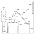
- FIG. 16 is an explanatory diagram for describing an application example of an imaging system according to an embodiment of the present disclosure.
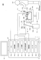
- FIG. 1 is a diagram illustrating an example of a schematic configuration of an endoscopic imaging system to which the technology according to the present disclosure can be applied, and the endoscopic imaging system is configured as a so-called endoscopic surgical system.
- FIG. 1 a state in which an operator (doctor) 167 is performing an operation on a patient 171 on a patient bed 169 using the endoscopic operation system 100 is illustrated.
- an endoscopic surgery system 100 includes an endoscope 101, other surgical tools 117, a support arm device 127 that supports the endoscope 101, and various devices for endoscopic surgery. And a cart 137 on which is mounted.
- trocars 125a to 125d are punctured into the abdominal wall. Then, the lens barrel 103 of the endoscope 101 and other surgical tools 117 are inserted into the body cavity of the patient 171 from the trocars 125a to 125d.
- an insufflation tube 119, an energy treatment tool 121, and forceps 123 are inserted into the body cavity of the patient 171.
- the energy treatment device 121 is a treatment device that performs incision and peeling of a tissue, sealing of a blood vessel, or the like by a high-frequency current or ultrasonic vibration.
- the illustrated surgical tool 117 is merely an example, and as the surgical tool 117, various surgical tools generally used in endoscopic surgery, such as a lever and a retractor, may be used.
- the image of the surgical site in the body cavity of the patient 171 captured by the endoscope 101 is displayed on the display device 141.
- the surgeon 167 performs a treatment such as excision of the affected part using the energy treatment tool 121 and the forceps 123 while viewing the image of the surgical part displayed on the display device 141 in real time.
- the pneumoperitoneum tube 119, the energy treatment device 121, and the forceps 123 are supported by an operator 167 or an assistant during the operation.
- the support arm device 127 includes an arm portion 131 extending from the base portion 129.
- the arm unit 131 includes joint units 133a, 133b, and 133c and links 135a and 135b, and is driven by control from the arm control device 145.
- the endoscope 101 is supported by the arm part 131, and its position and posture are controlled. Thereby, the stable position fixing of the endoscope 101 can be realized.
- the endoscope 101 includes a lens barrel 103 in which a region having a predetermined length from the distal end is inserted into the body cavity of the patient 171, and a camera head 105 connected to the proximal end of the lens barrel 103.
- a lens barrel 103 in which a region having a predetermined length from the distal end is inserted into the body cavity of the patient 171, and a camera head 105 connected to the proximal end of the lens barrel 103.
- an endoscope 101 configured as a so-called rigid mirror having a rigid barrel 103 is illustrated, but the endoscope 101 is configured as a so-called flexible mirror having a flexible barrel 103. Also good.
- An opening into which an objective lens is fitted is provided at the tip of the lens barrel 103.
- a light source device 143 is connected to the endoscope 101, and light generated by the light source device 143 is guided to the tip of the lens barrel by a light guide extending inside the lens barrel 103, and the objective 101 Irradiation is performed toward the observation target (in other words, the imaging target) in the body cavity of the patient 171 through the lens.
- the endoscope 101 may be a direct endoscope, a perspective mirror, or a side endoscope.
- An optical system and an image sensor are provided inside the camera head 105, and reflected light (observation light) from the observation target is condensed on the image sensor by the optical system. Observation light is photoelectrically converted by the imaging element, and an electrical signal corresponding to the observation light, that is, an image signal corresponding to the observation image is generated.
- the image signal is transmitted to a camera control unit (CCU: Camera Control Unit) 139 as RAW data.
- the camera head 105 has a function of adjusting the magnification and the focal length by appropriately driving the optical system.
- a plurality of image sensors may be provided in the camera head 105 in order to cope with, for example, stereoscopic viewing (3D display).
- a plurality of relay optical systems are provided inside the lens barrel 103 in order to guide the observation light to each of the plurality of imaging elements.
- the CCU 139 is configured by a CPU (Central Processing Unit), a GPU (Graphics Processing Unit), and the like, and comprehensively controls operations of the endoscope 101 and the display device 141. Specifically, the CCU 139 performs various types of image processing for displaying an image based on the image signal, such as development processing (demosaic processing), for example, on the image signal received from the camera head 105. The CCU 139 provides the display device 141 with the image signal subjected to the image processing. Further, the CCU 139 transmits a control signal to the camera head 105 to control the driving thereof.
- the control signal can include information regarding imaging conditions such as magnification and focal length.
- the display device 141 displays an image based on an image signal subjected to image processing by the CCU 139 under the control of the CCU 139.
- the endoscope 101 is compatible with high-resolution imaging such as 4K (horizontal pixel number 3840 ⁇ vertical pixel number 2160) or 8K (horizontal pixel number 7680 ⁇ vertical pixel number 4320), and / or 3D display
- high-resolution imaging such as 4K (horizontal pixel number 3840 ⁇ vertical pixel number 2160) or 8K (horizontal pixel number 7680 ⁇ vertical pixel number 4320)
- a display device 141 capable of high-resolution display and / or 3D display can be used.
- a more immersive feeling can be obtained by using a display device 141 having a size of 55 inches or more.
- a plurality of display devices 141 having different resolutions and sizes may be provided depending on applications.
- the light source device 143 includes a light source such as an LED (light emitting diode), and supplies irradiation light to the endoscope 101 when photographing a surgical site.
- a light source such as an LED (light emitting diode)
- the arm control device 145 is configured by a processor such as a CPU, for example, and operates according to a predetermined program to control driving of the arm portion 131 of the support arm device 127 according to a predetermined control method.
- the input device 147 is an input interface for the endoscopic surgery system 100.
- the user can input various information and instructions to the endoscopic surgery system 100 via the input device 147.
- the user inputs various types of information related to the operation, such as the patient's physical information and information about the surgical technique, via the input device 147.
- the user instructs to drive the arm unit 131 via the input device 147, or to change the imaging conditions (type of irradiation light, magnification, focal length, etc.) by the endoscope 101.
- An instruction or the like for driving the energy treatment device 121 is input.
- the type of the input device 147 is not limited, and the input device 147 may be various known input devices.
- the input device 147 for example, a mouse, a keyboard, a touch panel, a switch, a foot switch 157, and / or a lever can be applied.
- the touch panel may be provided on the display surface of the display device 141.
- the input device 147 is a device worn by the user, such as a glasses-type wearable device or an HMD (Head Mounted Display), for example, and various inputs according to the user's gesture and line of sight detected by these devices. Is done.
- the input device 147 includes a camera capable of detecting a user's movement, and various inputs are performed according to a user's gesture and line of sight detected from an image captured by the camera.
- the input device 147 includes a microphone capable of collecting a user's voice, and various inputs are performed by voice through the microphone.
- the input device 147 is configured to be able to input various kinds of information without contact, so that a user belonging to the clean area (for example, the operator 167) operates the device belonging to the unclean area in a non-contact manner. Is possible.
- the user since the user can operate the device without releasing his / her hand from the surgical tool he / she has, the convenience for the user is improved.
- the treatment instrument control device 149 controls driving of the energy treatment instrument 121 for tissue cauterization, incision, blood vessel sealing, or the like.
- the insufflation apparatus 151 supplies gas into the body cavity through the insufflation tube 119.
- the recorder 153 is a device that can record various types of information related to surgery.
- the printer 155 is a device that can print various types of information related to surgery in various formats such as text, images, or graphs.
- the support arm device 127 includes a base portion 129 that is a base, and an arm portion 131 that extends from the base portion 129.
- the arm part 131 is composed of a plurality of joint parts 133a, 133b, 133c and a plurality of links 135a, 135b connected by the joint part 133b.
- FIG. The structure of the arm part 131 is simplified and shown. Actually, the shape, number and arrangement of the joint portions 133a to 133c and the links 135a and 135b, the direction of the rotation axis of the joint portions 133a to 133c, and the like are appropriately set so that the arm portion 131 has a desired degree of freedom. obtain.
- the arm part 131 can be preferably configured to have a degree of freedom of 6 degrees or more.
- the endoscope 101 can be freely moved within the movable range of the arm portion 131, so that the barrel 103 of the endoscope 101 can be inserted into the body cavity of the patient 171 from a desired direction. It becomes possible.
- the joints 133a to 133c are provided with actuators, and the joints 133a to 133c are configured to be rotatable around a predetermined rotation axis by driving the actuators.
- the drive of the actuator is controlled by the arm control device 145
- the rotation angle of each joint part 133a to 133c is controlled, and the drive of the arm part 131 is controlled.
- the arm control device 145 can control the driving of the arm unit 131 by various known control methods such as force control or position control.
- the arm control device 145 appropriately controls the driving of the arm unit 131 according to the operation input.
- the position and posture of the endoscope 101 may be controlled. With this control, the endoscope 101 at the tip of the arm portion 131 can be moved from an arbitrary position to an arbitrary position and then fixedly supported at the position after the movement.
- the arm part 131 may be operated by what is called a master slave system. In this case, the arm unit 131 can be remotely operated by the user via the input device 147 installed at a location away from the operating room.
- the arm control device 145 When force control is applied, the arm control device 145 receives the external force from the user, and moves the actuators of the joint portions 133a to 133c so that the arm portion 131 moves smoothly according to the external force. You may perform what is called power assist control to drive. Thereby, when the user moves the arm unit 131 while directly touching the arm unit 131, the arm unit 131 can be moved with a relatively light force. Therefore, the endoscope 101 can be moved more intuitively and with a simpler operation, and the convenience for the user can be improved.
- the endoscope 101 is supported by a doctor called a scopist.
- the position of the endoscope 101 can be more reliably fixed without relying on human hands, so that an image of the surgical site can be stably obtained. It becomes possible to perform the operation smoothly.
- the arm control device 145 is not necessarily provided in the cart 137. Further, the arm control device 145 is not necessarily a single device. For example, the arm control device 145 may be provided in each joint portion 133a to 133c of the arm portion 131 of the support arm device 127, and the arm control device 145 cooperates with each other to drive the arm portion 131. Control may be realized.
- the light source device 143 supplies irradiation light to the endoscope 101 when photographing a surgical site.
- the light source device 143 includes a white light source configured by, for example, an LED, a laser light source, or a combination thereof.
- a white light source configured by a combination of RGB laser light sources
- the output intensity and output timing of each color can be controlled with high accuracy. Adjustments can be made.
- laser light from each of the RGB laser light sources is irradiated onto the observation target in a time-sharing manner, and the drive of the image sensor of the camera head 105 is controlled in synchronization with the irradiation timing, thereby corresponding to each RGB. It is also possible to take the images that have been taken in time division. According to this method, a color image can be obtained without providing a color filter in the image sensor.
- the driving of the light source device 143 may be controlled so as to change the intensity of light to be output every predetermined time. Synchronously with the timing of changing the intensity of the light, the drive of the image sensor of the camera head 105 is controlled to acquire images in a time-sharing manner, and the images are synthesized, so that high dynamics without so-called blackout and overexposure are obtained. A range image can be generated.
- the light source device 143 may be configured to be able to supply light of a predetermined wavelength band corresponding to special light observation.
- special light observation for example, by utilizing the wavelength dependence of light absorption in body tissue, the surface of the mucous membrane is irradiated by irradiating light in a narrow band compared to irradiation light (ie, white light) during normal observation.
- narrow band imaging is performed in which a predetermined tissue such as a blood vessel is imaged with high contrast.
- fluorescence observation may be performed in which an image is obtained by fluorescence generated by irradiating excitation light.
- the body tissue is irradiated with excitation light to observe fluorescence from the body tissue (autofluorescence observation), or a reagent such as indocyanine green (ICG) is locally administered to the body tissue and applied to the body tissue.
- a reagent such as indocyanine green (ICG)
- ICG indocyanine green
- the light source device 143 can be configured to be able to supply narrowband light and / or excitation light corresponding to such special light observation.
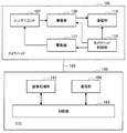
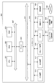
- FIG. 2 is a block diagram illustrating an example of functional configurations of the camera head 105 and the CCU 139 illustrated in FIG.
- the camera head 105 includes a lens unit 107, an imaging unit 109, a driving unit 111, a communication unit 113, and a camera head control unit 115 as functions thereof.
- the CCU 139 includes a communication unit 159, an image processing unit 161, and a control unit 163 as its functions.
- the camera head 105 and the CCU 139 are connected to each other via a transmission cable 165 so that they can communicate with each other.
- the lens unit 107 is an optical system provided at a connection portion with the lens barrel 103. Observation light taken from the tip of the lens barrel 103 is guided to the camera head 105 and enters the lens unit 107.
- the lens unit 107 is configured by combining a plurality of lenses including a zoom lens and a focus lens. The optical characteristics of the lens unit 107 are adjusted so that the observation light is condensed on the light receiving surface of the image sensor of the imaging unit 109. Further, the zoom lens and the focus lens are configured such that their positions on the optical axis are movable in order to adjust the magnification and focus of the captured image.
- the image pickup unit 109 is configured by an image pickup device, and is arranged at the rear stage of the lens unit 107.
- the observation light that has passed through the lens unit 107 is collected on the light receiving surface of the image sensor, and an image signal corresponding to the observation image is generated by photoelectric conversion.
- the image signal generated by the imaging unit 109 is provided to the communication unit 113.
- CMOS Complementary Metal Oxide Semiconductor
- the imaging element for example, an element capable of capturing a high-resolution image of 4K or more may be used.
- the image sensor that configures the image capturing unit 109 is configured to include a pair of image sensors for acquiring right-eye and left-eye image signals corresponding to 3D display. By performing the 3D display, the operator 167 can more accurately grasp the depth of the living tissue in the surgical site.
- the imaging unit 109 is configured as a multi-plate type, a plurality of lens units 107 are also provided corresponding to each imaging element.
- the imaging unit 109 is not necessarily provided in the camera head 105.
- the imaging unit 109 may be provided inside the lens barrel 103 immediately after the objective lens.
- the driving unit 111 is constituted by an actuator, and moves the zoom lens and the focus lens of the lens unit 107 by a predetermined distance along the optical axis under the control of the camera head control unit 115. Thereby, the magnification and the focus of the image captured by the imaging unit 109 can be adjusted as appropriate.
- the communication unit 113 includes a communication device for transmitting and receiving various types of information to and from the CCU 139.
- the communication unit 113 transmits the image signal obtained from the imaging unit 109 as RAW data to the CCU 139 via the transmission cable 165.
- the image signal is preferably transmitted by optical communication.
- the operator 167 performs the operation while observing the state of the affected part with the captured image, so that a moving image of the operated part is displayed in real time as much as possible for a safer and more reliable operation. Because it is required.
- the communication unit 113 is provided with a photoelectric conversion module that converts an electrical signal into an optical signal.
- the image signal is converted into an optical signal by the photoelectric conversion module, and then transmitted to the CCU 139 via the transmission cable 165.
- the communication unit 113 receives a control signal for controlling the driving of the camera head 105 from the CCU 139.
- the control signal includes, for example, information for designating the frame rate of the captured image, information for designating the exposure value at the time of imaging, and / or information for designating the magnification and focus of the captured image. Contains information about the condition.
- the communication unit 113 provides the received control signal to the camera head control unit 115.
- the control signal from the CCU 139 may also be transmitted by optical communication.
- the communication unit 113 is provided with a photoelectric conversion module that converts an optical signal into an electrical signal.
- the control signal is converted into an electrical signal by the photoelectric conversion module, and then provided to the camera head control unit 115.
- the imaging conditions such as the frame rate, exposure value, magnification, and focus are automatically set by the control unit 163 of the CCU 139 based on the acquired image signal. That is, a so-called AE (Auto Exposure) function, AF (Auto Focus) function, and AWB (Auto White Balance) function are mounted on the endoscope 101.
- AE Auto Exposure
- AF Automatic Focus
- AWB Automatic White Balance
- the camera head control unit 115 controls driving of the camera head 105 based on a control signal from the CCU 139 received via the communication unit 113. For example, the camera head control unit 115 controls driving of the imaging element of the imaging unit 109 based on information indicating that the frame rate of the captured image is specified and / or information indicating that the exposure at the time of imaging is specified. For example, the camera head control unit 115 appropriately moves the zoom lens and the focus lens of the lens unit 107 via the driving unit 111 based on information indicating that the magnification and the focus of the captured image are designated.
- the camera head control unit 115 may further have a function of storing information for identifying the lens barrel 103 and the camera head 105.
- the camera head 105 can be resistant to autoclave sterilization by arranging the lens unit 107, the imaging unit 109, and the like in a sealed structure with high airtightness and waterproofness.
- the communication unit 159 is configured by a communication device for transmitting and receiving various types of information to and from the camera head 105.
- the communication unit 159 receives an image signal transmitted from the camera head 105 via the transmission cable 165.
- the image signal can be suitably transmitted by optical communication.
- the communication unit 159 is provided with a photoelectric conversion module that converts an optical signal into an electric signal.
- the communication unit 159 provides the image processing unit 161 with the image signal converted into an electrical signal.
- the communication unit 159 transmits a control signal for controlling the driving of the camera head 105 to the camera head 105.
- the control signal may also be transmitted by optical communication.
- the image processing unit 161 performs various types of image processing on the image signal that is RAW data transmitted from the camera head 105. Examples of the image processing include development processing, high image quality processing (band enhancement processing, super-resolution processing, NR (Noise reduction) processing and / or camera shake correction processing, etc.), and / or enlargement processing (electronic zoom processing). Various known signal processing is included.
- the image processing unit 161 performs detection processing on the image signal for performing AE, AF, and AWB.
- the image processing unit 161 is configured by a processor such as a CPU or a GPU, and the above-described image processing and detection processing can be performed by the processor operating according to a predetermined program.
- the image processing unit 161 is configured by a plurality of GPUs, the image processing unit 161 appropriately divides information related to the image signal, and performs image processing in parallel by the plurality of GPUs.
- the control unit 163 performs various controls related to imaging of the surgical site by the endoscope 101 and display of the captured image. For example, the control unit 163 generates a control signal for controlling the driving of the camera head 105. At this time, when the imaging condition is input by the user, the control unit 163 generates a control signal based on the input by the user. Alternatively, when the endoscope 101 is equipped with the AE function, the AF function, and the AWB function, the control unit 163 determines the optimal exposure value, focal length, and the distance according to the detection processing result by the image processing unit 161. A white balance is appropriately calculated and a control signal is generated.
- control unit 163 causes the display device 141 to display an image of the surgical unit based on the image signal subjected to the image processing by the image processing unit 161.
- the control unit 163 recognizes various objects in the surgical unit image using various image recognition techniques. For example, the control unit 163 detects the shape or color of the edge of the object included in the surgical site image, thereby removing surgical tools such as forceps, specific biological parts, bleeding, mist when using the energy treatment tool 121, and the like. Can be recognized.
- the control unit 163 displays various types of surgery support information on the image of the surgical site using the recognition result. The surgery support information is displayed in a superimposed manner and presented to the operator 167, so that the surgery can be performed more safely and reliably.
- the transmission cable 165 connecting the camera head 105 and the CCU 139 is an electric signal cable corresponding to electric signal communication, an optical fiber corresponding to optical communication, or a composite cable thereof.
- communication is performed by wire using the transmission cable 165, but communication between the camera head 105 and the CCU 139 may be performed wirelessly.
- communication between the two is performed wirelessly, there is no need to lay the transmission cable 165 in the operating room, so that the situation where the movement of the medical staff in the operating room is hindered by the transmission cable 165 can be solved.
- the endoscopic surgery system 100 to which the technology according to the present disclosure can be applied has been described.
- the endoscopic surgery system 100 has been described as an example, a system to which the technology according to the present disclosure can be applied is not limited to such an example.
- the technology according to the present disclosure may be applied to a testing flexible endoscope system or a microscope operation system.
- a fluorescent substance that has an affinity for a lesion such as cancer is administered to a subject (patient) in advance and irradiated with excitation light to excite the fluorescent substance.
- the lesion is observed with a fluorescent image of the fluorescence emitted from (ie, an observation image based on the fluorescence detection result).
- a typical example of a fluorescent material used for fluorescence observation is indocyanine green (ICG).
- the ICG emits fluorescence having a wavelength around 820 nm (that is, light in the near-infrared band) by using light having a wavelength near 808 nm as excitation light.
- FIG. 3 is an explanatory diagram for explaining an example of the relationship between various fluorescent materials used in fluorescence observation and the wavelength band of fluorescence emitted by the fluorescent materials.
- fluorescence in the visible light band such as fluorescein, 5-aminolevulinic acid (5ALA), rezaphyrin and the like is used. Fluorescent materials that emit light have also been proposed. More specifically, fluorescein emits fluorescence in the visible light region around 520 nm (in particular, the wavelength band of the G component). Further, 5ALA emits fluorescence in the visible light region around 635 nm (in particular, the wavelength band of the R component).
- Rezaphyrin emits fluorescence in the vicinity of the wavelength band of 670 nm to 730 nm, that is, fluorescence in the visible light region (particularly, near the near infrared region) to the near infrared region.
- the example of the fluorescent material shown in FIG. 3 is merely an example, and various fluorescent materials other than the example shown in FIG. 3 have been proposed.
- the near-infrared wavelength band in the vicinity of 650 nm to 1000 nm is known as a wavelength band that allows light to easily pass through a living body, and is also called a “biological window”.
- FIG. 5 schematically shows the wavelength band of light used in the analysis method for analyzing the constituent components of the substance to be observed (in other words, imaging target). Utilizing such characteristics, for example, as a fluorescent substance that enables observation of a deeper part of the body of the subject to be examined, fluorescence that belongs to the window of the living body or fluorescence that belongs to the wavelength band near the window of the living body is emitted.
- fluorescent materials have also been proposed.
- an imaging device for example, a camera head
- the imaging device includes, for example, at least a part of the wavelength band of the fluorescence emitted by the fluorescent material, and light in another wavelength band different from the light in the wavelength band (for example, visible light or excitation light).
- a specific configuration for example, a branching optical system or a filter. That is, in fluorescence observation using a predetermined fluorescent material, a dedicated imaging device is often used to observe a fluorescent image of fluorescence emitted from the fluorescent material.
- a dedicated imaging device (camera head) is used for each fluorescent substance.
- Such a use form may be a factor that complicates operations related to fluorescence observation because it is necessary to attach and detach the imaging device.
- it since it is necessary to prepare an imaging device for each fluorescent substance to be used, it may be a factor that increases costs. For this reason, in the present disclosure, it is possible to observe fluorescence emitted from each of a plurality of types of fluorescent materials by using a single imaging device, and thus, even in a situation where a plurality of types of fluorescent materials are selectively used.
- An imaging system capable of capturing a fluorescent image corresponding to a fluorescent substance is proposed.
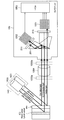
- FIG. 4 is an explanatory diagram for describing an example of a schematic configuration of a camera head and a light source device in the imaging system according to the present embodiment.
- an endoscope or the like is applied to a fluorescent substance previously administered to the subject to be examined.
- the light source device 143 includes a visible light source 1431 that emits light (corresponding to an example of “first light”) belonging to the visible light wavelength band, and a near-infrared wavelength band. And a near-infrared light source 1433 that emits light belonging to (corresponding to an example of “second light”).
- the visible light source 1431 is configured to be able to irradiate light continuously distributed in the visible light wavelength band.
- the visible light source 1431 is configured to be capable of emitting light having a peak whose intensity is equal to or greater than a predetermined threshold at at least one or more predetermined wavelength positions in the visible light wavelength band.
- the light output (that is, the intensity) corresponding to at least a part of the wavelength positions can be controlled.
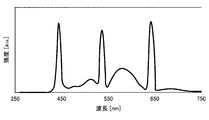
- FIG. 5 shows an example of the spectrum of light belonging to the visible light wavelength band emitted from the light source device according to this embodiment, and corresponds to the spectrum of light emitted from the visible light source 1431.
- the horizontal axis indicates the wavelength
- the vertical axis indicates the light intensity as a relative value.
- the visible light source 1431 corresponds to light continuously distributed in the visible light wavelength band (corresponding to an example of “fourth light”), R component, G component, and B component. In each wavelength position in the wavelength band to be emitted, light having a peak with higher intensity than the continuously distributed light (corresponding to an example of “third light”) can be emitted.
- the visible light source 1431 is a laser light source (referred to as an “RGB laser light source”) configured to output light having a peak at a wavelength position in each wavelength band of the R component, the G component, and the B component.
- an LED light source configured to be capable of outputting white light (corresponding to “white light source”, hereinafter also referred to as “white LED”).
- each of light having a peak at each wavelength position in the wavelength band corresponding to the R component, G component, and B component emitted from the RGB laser light source is simply referred to as “R component”, “G Sometimes referred to as “component” and “B component”.
- the visible light source 1431 may be configured to be capable of independently controlling the outputs of the RGB laser light source and the white light source (white LED). Further, the RGB laser light source is configured to be controllable so that the output of at least a part of the R component, the G component, and the B component is temporarily attenuated or temporarily turned off, for example.
- the RGB laser light source has a wavelength of fluorescence emitted from at least a predetermined fluorescent material (particularly, a fluorescent material that emits fluorescence in the visible light wavelength band) among the R component, G component, and B component. The light output corresponding to the wavelength position included in the band or located near the wavelength band of the fluorescence is configured to be controllable.
- the RGB laser light source outputs an R component as light at a wavelength position that is included in or near the fluorescence wavelength band emitted by a fluorescent material such as 5ALA or reserphyrin. May be configured to be controllable.
- the RGB laser light source outputs G component as light at a wavelength position that is included in the wavelength band of fluorescence emitted by a fluorescent material such as fluorescein, or is located in the vicinity of the wavelength band of the fluorescence. It may be configured to be controllable.
- the RGB laser light source may be configured to be able to individually control the outputs of the R component, the G component, and the B component, or to be controlled so as to be linked with respect to at least two or more components.
- the RGB laser light source may be configured to be controllable so that the output of each of the R component, the G component, and the B component is continuously changed, and is configured to be able to switch the output on and off. May be.
- the near-infrared light source 1433 includes a light source that emits light in the near-infrared wavelength band (that is, “near-infrared light source”), and emits light in at least a part of the wavelength band in the near-infrared wavelength band. It is configured to be able to emit light. More specifically, the near-infrared light source 1433 includes a predetermined wavelength band including at least a part of the excitation wavelength of a predetermined fluorescent substance (particularly, a fluorescent substance excited by light belonging to the near-infrared wavelength band). It is configured to be able to output light in the wavelength band.
- the light source device 143 emits light belonging to the visible light wavelength band and light belonging to the near-infrared wavelength band toward the imaging target.
- the visible light wavelength band is reflected by the surface of the skin of the person to be inspected and enters the camera head 105 via the optical system unit 1054 described later.
- the light belonging to the near-infrared wavelength band the light that does not belong to the window of the living body is reflected by the surface of the subject's skin and enters the camera head 105 via the optical system unit 1054.
- the light belonging to the window of the living body among the light belonging to the near-infrared wavelength band passes through the skin of the subject to be examined and reaches the inside of the body, and is irradiated to the body tissue such as blood vessels or lymphatic vessels.
- ICG or the like that is preliminarily administered to the subject to be examined and deposited on some tissues (for example, lesions) by components of at least some of the wavelength bands of the light that has reached the subject's body.
- the fluorescent material is excited, and fluorescence is emitted from the fluorescent material. Fluorescence emitted from the fluorescent substance (that is, fluorescence belonging to the near-infrared wavelength band) passes through the skin of the subject to be examined and exits from the body, and enters the camera head 105 via the optical system unit 1054.
- the camera head 105 includes a branching optical system 201, filters 211 and 213, a visible light image capturing image sensor 1051, a near-infrared light image capturing image sensor 1052, and an FPGA 1053. Including.
- the camera head 105 is configured such that a predetermined optical system unit 1054 can be mounted in a stage before the entrance to the camera head 105. Further, the camera head 105 is configured so that a notch filter 1055 can be attached in a stage preceding the entrance to the camera head 105.
- the notch filter 1055 may be mounted in front of the optical system unit 1054 as indicated by reference numeral 1055a. As another example, the notch filter 1055 may be mounted so as to be interposed between the optical system unit 1054 and the camera head 105, as indicated by reference numeral 1055b.
- the optical system unit 1054 has a configuration for collecting external light and guiding the collected light into the camera head 105.
- the optical system unit 1054 includes, for example, an imaging optical system configured by a lens or the like, and collects the collected light using the imaging optical system, and the imaging element 1051 for imaging a visible light image provided inside the camera head 105. Or an image is formed on the imaging element 1052 for imaging near-infrared light.
- the optical system unit 1054 generates an image of the imaging target by taking in external light, and outputs the generated image to the camera head 105 located at the subsequent stage.
- the optical system unit 1054 may include, for example, a magnifying optical system that magnifies the generated image of the imaging target.
- Specific examples of the optical system unit 1054 include a detachable lens unit, a lens barrel in an endoscope, and an objective lens in a microscope.
- the notch filter 1055 is configured to be detachable with respect to the front stage of the camera head 105, and blocks light in a part of the wavelength band among light incident on the camera head 105 via the optical system unit 1054. It has characteristics. A plurality of types of notch filters 1055 having different wavelength bands to be blocked may be selectively attached to the camera head 105 or the optical system unit 1054. As a specific example, a notch filter 1055 that blocks light in at least a part of the wavelength band of the excitation wavelength of the fluorescent material is attached to the camera head 105 or the optical system unit 1054 according to the fluorescent material used. May be. With such a configuration, it is possible to prevent the excitation light of the fluorescent material from entering the camera head 105 by the notch filter 1055 when capturing a fluorescent image of the fluorescence emitted by the fluorescent material. .
- the branching optical system 201 includes, for example, a prism having a dichroic film therein, and separates (branches) incident light into light belonging to the visible light wavelength band and light belonging to the near-infrared wavelength band. ). Then, the branching optical system 201 guides the light belonging to the separated visible light wavelength band to the imaging element 1051 for imaging the visible light image, and the near-infrared light for the separated light belonging to the near-infrared wavelength band. The light is guided to the image pickup device 1052 for image pickup.
- a filter 211 is provided in the optical path of light (that is, visible light) that is separated by the branching optical system 201 and guided to the imaging element 1051 for imaging a visible light image.
- the filter 211 mainly has a characteristic of transmitting light belonging to the visible light wavelength band and blocking at least light belonging to the near-infrared wavelength band.
- a filter 213 is provided in the optical path of light (that is, near-infrared rays) that is separated by the branching optical system 201 and guided to the imaging device 1052 for imaging near-infrared light images.
- the filter 213 mainly includes at least a part of a wavelength band of fluorescence emitted from a predetermined fluorescent material (specifically, a fluorescent material emitting fluorescence in the near infrared wavelength band such as ICG) in the near infrared wavelength band. It has a characteristic of transmitting light belonging to the wavelength band and blocking at least light belonging to the visible light wavelength band.
- a predetermined fluorescent material specifically, a fluorescent material emitting fluorescence in the near infrared wavelength band such as ICG
- the imaging device 1051 for imaging a visible light image is provided after the branching optical system 201 and the filter 211, and is imaged by the light belonging to the visible light wavelength band that is separated by the branching optical system 201 and transmitted through the filter 211. It is an element.
- the visible light image capturing device 1051 for example, an image capturing device such as a CCD or CMOS having an RGB color filter can be applied.
- the imaging device 1052 for imaging near-infrared light is provided at the subsequent stage of the branching optical system 201 and the filter 213, separated by the branching optical system 201, and at least part of the near-infrared wavelength band transmitted through the filter 213.
- an image sensor on which light belonging to a wavelength band (in other words, a wavelength band including at least a part of a wavelength band of fluorescence emitted by a predetermined fluorescent material) is imaged.
- a more sensitive image capturing element for example, an image capturing element such as a CCD or CMOS without a color filter or the like may be applied. .
- An FPGA (field-programmable gate array) 1053 corresponds to a control unit that controls various operations of the camera head 105, and displays the imaging results of the visible light image capturing image sensor 1051 and the near-infrared light image capturing image sensor 1052. Based on this, an image of the imaging target is generated. As a specific example, the FPGA 1053 generates a visible light image of the imaging target based on the imaging result of the imaging device 1051 for imaging a visible light image. Further, the FPGA 1053 generates a near-infrared light image of the object to be imaged based on the imaging result obtained by the near-infrared light image capturing element 1052.
- the FPGA 1053 performs a near-infrared light image (in other words, fluorescent light) based on the imaging result of the near-infrared light image capturing image sensor 1052 with respect to the visible light image based on the imaging result of the visible light image capturing image sensor 1051. An image on which (image) is superimposed may be generated.
- the imaging element 1051 for imaging a visible light image is arranged so that the optical axis of visible light emitted from the branching optical system 201 and transmitted through the filter 211 forms an image at the center.
- the near-infrared light image pickup image sensor 1052 is configured so that the screen displacement of the near-infrared light image with respect to the visible light image generated based on the image pickup result of the visible light image pickup image pickup element 1051 is minimized.
- the fixed position is determined while performing shift adjustment in a direction perpendicular to the axis. With such a configuration, when the visible light image and the near-infrared light image (fluorescence image) are superimposed, the alignment of both images can be made simpler.
- the fixed position of the near-infrared light image pickup image sensor 1052 is determined without performing the position adjustment as described above, and the near-red color with respect to the visible light image generated due to the component error is determined.
- the size of the screen shift of the external light image (fluorescence image) is specified in advance, and the reading start position of the near-infrared light image signal is shifted so that the specified screen shift is minimized. Also good.
- the adjustment process as described above can be omitted, which is advantageous in terms of cost.
- FIGS. 4 and 5 an example of a schematic configuration of the camera head and the light source device in the imaging system according to the present embodiment has been described with reference to FIGS. 4 and 5.
- an example of a more detailed configuration of the camera head in the imaging system according to the present embodiment will be described for each of a case where it is configured as a two-plate type camera head and a case where it is configured as a three-plate type camera head. To do.
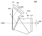
- FIG. 6 is an explanatory view schematically showing an example of the configuration of the camera head according to the present embodiment.
- the camera head 105 shown in FIG. 6 when the camera head 105 shown in FIG. 6 is explicitly shown, it may be referred to as “camera head 105a”.
- the camera head 105 a includes a color separation prism 201 a, a visible light image capturing image sensor 1051, a near infrared light image capturing image sensor 1052, a notch filter 1055, and a short pass filter 211. And a long pass filter 213.
- the visible light image capturing element 1051 and the near infrared light image capturing element 1052 are the visible light image capturing element 1051 and the near infrared light image capturing element described with reference to FIG. Since it is the same structure as 1052, detailed description is abbreviate
- the color separation prism 201a is an optical member that separates light belonging to the visible light wavelength band and light belonging to the near-infrared wavelength band with respect to incident light incident on the camera head 105a.
- the branching optical system shown in FIG. This corresponds to an example of 201.
- a dichroic film 203 for separating light belonging to the visible light wavelength band and light belonging to the near infrared wavelength band is provided inside the color separation prism 201a.
- the color separation prism 201 a is a prism in which a first prism 205 and a second prism 207 are joined to each other via a dichroic film 203. That is, the dichroic film 203 is provided at the interface between the first prism 205 and the second prism 207.
- the dichroic film 203 is the incident light including the light belonging to the visible light wavelength band and the light belonging to the near-infrared wavelength band incident on the color separation prism 201a, and the light belonging to the visible light wavelength band and the near-infrared light. It is an optical film that separates light belonging to a wavelength band. Specifically, the dichroic film 203 has characteristics of reflecting light belonging to the visible light wavelength band and transmitting light belonging to the near-infrared wavelength band. Details of the spectral characteristics of the dichroic film 203 will be described later.
- the first prism 205 is an optical path for visible light through which light belonging to the visible light wavelength band and light belonging to the near-infrared wavelength band (that is, incident light) are incident and light belonging to the visible light wavelength band is guided. It is a functioning prism.
- the second prism 207 is a prism that functions as an optical path for near infrared light through which light belonging to the near infrared wavelength band is guided.
- Incident light that has entered the first prism 205 travels straight through the first prism 205, and belongs to the visible light wavelength band and the near-infrared wavelength band by the dichroic film 203 provided obliquely on the optical axis. Separated into light.
- the light belonging to the visible light wavelength band is reflected by the dichroic film 203 and guided through the first prism 205.
- the reflected and separated light belonging to the visible light wavelength band (that is, visible light) is totally reflected once at the position A shown in FIG. 6 and transmitted to the outside of the first prism 205.
- membrane 203 can be closely approached.
- the installation angle of the dichroic film 203 according to the present embodiment on the optical axis is set such that the visible light total reflection condition at the position A is satisfied.
- the dichroic film 203 By disposing the dichroic film 203 in this way, even when a light beam having a bright F value is incident on the first prism 205, the spectral characteristics of the dichroic film 203 due to the difference in incident angle between the upper light beam and the lower light beam. The change can be suppressed, and the wavelength separation can be performed with high accuracy.
- the visible light transmitted through the first prism 205 is guided to the imaging element 1051 for imaging a visible light image.
- a short pass filter 211 is provided in the optical path of the light that is separated by the dichroic film 203 and forms an image on the imaging element 1051 for imaging a visible light image.
- the short pass filter 211 transmits light having a wavelength equal to or less than the boundary (that is, light including visible light) at a boundary of 750 nm, which is a boundary between the visible light wavelength band and the near-infrared wavelength band, and exceeds the boundary.
- Blocks light of wavelength ie, light including near infrared light.
- light belonging to the near-infrared wavelength band transmitted through the dichroic film 203 enters the second prism 207 and travels straight through the second prism 207.
- the end surface of the second prism 207 opposite to the side on which the dichroic film 203 is provided is perpendicular to the optical axis.
- the light that is provided and belongs to the near-infrared wavelength band is transmitted to the outside of the second prism 207 while maintaining a state perpendicular to the emission surface of the second prism 207.
- the near-infrared ray that has passed through the second prism 207 is guided to the imaging element 1052 for taking a near-infrared light image.
- a long-pass filter 213 is provided in the optical path of the light that is separated by the dichroic film 203 and forms an image on the imaging device 1052 for taking a near-infrared light image.
- the long pass filter 213 has a reverse polarity characteristic to the short pass filter 211.
- the long pass filter 213 transmits light having a wavelength longer than the boundary (that is, light including near infrared light) with 750 nm serving as a boundary between the visible light wavelength band and the near infrared wavelength band as a boundary, Block light with a wavelength below the boundary (ie, light including visible light).
- the boundary that is, light including near infrared light
- Block light with a wavelength below the boundary ie, light including visible light
- the material of the color separation prism 201a according to the present embodiment is not particularly limited, and a known optical glass or optical crystal is used depending on the wavelength of light guided through the color separation prism 201a. It can be used as appropriate.
- the notch filter 1055 is configured to be detachable in front of the color separation prism 201a.
- a filter having a characteristic of blocking light in a wavelength band of at least a part of the excitation wavelength of the fluorescent material may be attached according to the fluorescent material used. It becomes possible.
- a filter that blocks light in the vicinity of 808 nm, which is the excitation wavelength of ICG may be attached as notch filter 1055.
- an example of the configuration of the camera head in the imaging system As described above, with reference to FIG. 6, as an example of the configuration of the camera head in the imaging system according to the present embodiment, an example of the configuration of the two-plate camera head, in particular, incident light is transmitted to the imaging device via the branch optical system.
- the description has been given focusing on the configuration up to image formation.
- the configuration of the camera head described in FIG. 6 is merely an example, and is not necessarily limited to the example illustrated in FIG.
- the installation position of the imaging device 1051 for capturing a visible light image and the imaging device 1052 for capturing a near-infrared light image may be reversed.
- a dichroic film having a characteristic of transmitting light belonging to the visible light wavelength band and reflecting light belonging to the near-infrared wavelength band may be applied as the dichroic film 203. That is, the characteristics of the dichroic film 203 may be changed as appropriate in accordance with the relationship between the positions where the visible light image capturing device 1051 and the near infrared light image capturing device 1052 are installed.
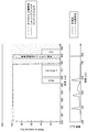
- FIG. 7 is an explanatory diagram for explaining an example of the relationship between the spectral characteristics of the dichroic film and various filters according to the present embodiment and the spectrum of light emitted from the light source device.
- the upper diagram of FIG. 7 schematically shows the spectral characteristics of the dichroic film 203, the notch filter 1055, the short pass filter 211, and the long pass filter 213.
- the upper diagram of FIG. 7 schematically shows the spectral characteristics of the dichroic film 203, the notch filter 1055, the short pass filter 211, and the long pass filter 213.
- the horizontal axis indicates the wavelength
- the vertical axis indicates the characteristics relating to transmission or reflection of the dichroic film and various filters as relative values (%).
- the lower diagram in FIG. 7 shows a spectrum of light emitted from the light source device according to the present embodiment.
- the horizontal axis indicates the wavelength
- the vertical axis indicates the characteristics relating to transmission or reflection of the dichroic film and various filters as relative values (%).
- the position of the horizontal axis in the upper diagram corresponds to the position of the horizontal axis in the lower diagram.
- the light source device emits light in the vicinity of 808 nm which is the excitation wavelength of ICG (that is, excitation light of ICG) as light in the near infrared wavelength band. That is, in the example shown in FIG. 7, a notch filter that blocks light in the vicinity of 808 nm which is the ICG excitation wavelength is applied as the notch filter 1055.
- the graph shown as the dichroic film characteristic schematically shows the respective wavelength bands of the light reflected by the dichroic film 203 shown in FIG. 6 and the light transmitted through the dichroic film 203.
- the inside of the graph shown as the dichroic film characteristic corresponds to a component reflected by the dichroic film 203
- the outside of the graph corresponds to a component that passes through the dichroic film 203. That is, the dichroic film 203 reflects a large part (for example, 90% or more) of light in the wavelength band of 350 nm to 750 nm and transmits a large part (for example, 90% or more) of light in the wavelength band exceeding 750 nm. have.
- the graph shown as the characteristics of the short pass filter schematically shows the wavelength bands of the light transmitted through the short pass filter 211 shown in FIG. 6 and the light blocked by the short pass filter 211.
- the short-pass filter 211 transmits light having a wavelength equal to or less than the boundary (that is, light including visible light) with 750 nm serving as a boundary between the visible light wavelength band and the near-infrared wavelength band as a boundary.
- Light having a wavelength exceeding the boundary that is, light including near infrared light
- the graph shown as the characteristics of the long pass filter schematically shows the respective wavelength bands of the light transmitted through the long pass filter 213 shown in FIG. 6 and the light blocked by the long pass filter 213.
- the long-pass filter 213 transmits light having a wavelength longer than the boundary (that is, light including near-infrared light) with 750 nm serving as a boundary between the visible light wavelength band and the near-infrared wavelength band as a boundary. And light with a wavelength below the boundary (that is, light including visible light) is blocked.
- notch filter 1055 a filter that blocks light in the vicinity of 808 nm, which is the excitation wavelength of the ICG, is mounted in front of the color separation prism 201a. Therefore, among the light belonging to the near-infrared wavelength band guided into the camera head 105a, light in the vicinity of 808 nm which is the excitation wavelength of ICG is blocked by the notch filter 1055.
- the camera head 105a can be used, for example, a fluorescent image of fluorescence belonging to a near-infrared wavelength band emitted by a fluorescent substance such as ICG, or a visible light wavelength band emitted by a fluorescent substance such as 5ALA and Rezaphyrin. It is possible to take a fluorescent image of the fluorescence belonging to.
- the fluorescence emitted by the ICG belongs to the near-infrared wavelength band
- the image pickup for near-infrared light imaging is performed via the color separation prism 201a and the long-pass filter 213.
- An image is formed on the element 1052.
- the ICG excitation light is blocked by the notch filter 1055 before entering the camera head 105a.
- a visible light image of the imaging target is captured independently of the fluorescent fluorescence image emitted by the ICG based on the imaging result by the imaging device 1051 for imaging a visible light image. It is possible. Therefore, in this case, for example, it is also possible to superimpose a fluorescence image of fluorescence emitted by ICG on the visible light image of the imaging object.
- the fluorescence emitted by 5ALA belongs to the visible light wavelength band
- the wavelength band of fluorescence emitted by 5ALA at least partially overlaps the wavelength band of the R component. Therefore, when capturing a fluorescent image of fluorescence emitted by 5ALA, at least from the RGB laser light source of the visible light source 1431 among the light belonging to the visible light wavelength band irradiated from the visible light source 1431 of the light source device 143.
- the visible light image pickup image sensor 1051 passes through the color separation prism 201 a and the short pass filter 211. To form an image. Therefore, it is possible to observe the fluorescence image of the fluorescence emitted by the resaphyrin by the visible light image generated based on the imaging result by the imaging element 1051 for imaging the visible light image.
- the camera head 105a may be equipped with a notch filter 1055 that blocks light belonging to the excitation wavelength of the fluorescent material.
- excitation light having a wavelength of 405 nm it is also possible to use excitation light having a wavelength of 405 nm as excitation light for resaphyrin.
- a notch filter 1055 that blocks the excitation light that is, light having a wavelength of 405 nm
- a long pass filter may be attached to the camera head 105a instead of the notch filter 1055. With such a configuration, it is possible to prevent the excitation light from entering the camera head 105a.
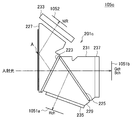
- FIG. 8 is an explanatory view schematically showing another example of the configuration of the camera head according to the present embodiment.
- the camera head 105 shown in FIG. 8 when the camera head 105 shown in FIG. 8 is explicitly shown, it may be referred to as “camera head 105b”.
- the camera head 105 b includes a color separation prism 201 b, a visible light image capturing image sensor 1051, a near infrared light image capturing image sensor 1052, a short pass filter 211, and a band pass filter 215.
- the color separation prism 201b has the same configuration as the color separation prism 201a described with reference to FIG. 6, and corresponds to an example of the branching optical system 201 shown in FIG. That is, the camera head 105b shown in FIG. 8 does not have the notch filter 1055, and has a bandpass filter 215 instead of the longpass filter 213, compared to the camera head 105a described with reference to FIG. Is different. Therefore, in the present description, the configuration of the camera head 105b will be described by focusing on the difference from the camera head 105a shown in FIG. 6, and detailed description of the same configuration as the camera head 105a will be omitted.
- the camera head 105b is separated by the dichroic film 203, and the band pass filter 215 is provided in the optical path of the light imaged on the imaging device 1052 for imaging the near infrared light image.
- the band-pass filter 215 transmits light in at least a part of the predetermined wavelength band according to the characteristics of the fluorescent substance that emits fluorescence in the predetermined wavelength band in the near-infrared wavelength band, and transmits other wavelengths. It has the property of blocking light in the band.
- the bandpass filter 215 when focusing on the fluorescence emitted by the ICG, the bandpass filter 215 emits light having a wavelength band around 820 nm (for example, a wavelength band of 820 nm to 850 nm) that is the wavelength band of the fluorescence emitted by the ICG. It only needs to have a characteristic of transmitting and blocking light in other wavelength bands.
- the camera head 105b is provided with the band-pass filter 215 in the preceding stage of the imaging element 1052 for imaging near-infrared light images. Therefore, when focusing on the fluorescence belonging to the near-infrared wavelength band emitted by a fluorescent material such as ICG, the camera head 105b emits excitation light of the fluorescent material even if the notch filter 1055 is not provided like the camera head 105a.
- the band-pass filter 215 can prevent it.
- the configuration of the camera head described in FIG. 8 is merely an example, and is not necessarily limited to the example illustrated in FIG.
- the installation position of the imaging device 1051 for capturing a visible light image and the imaging device 1052 for capturing a near-infrared light image may be reversed.
- a dichroic film having a characteristic of transmitting light belonging to the visible light wavelength band and reflecting light belonging to the near-infrared wavelength band may be applied as the dichroic film 203. That is, the characteristics of the dichroic film 203 may be changed as appropriate in accordance with the relationship between the positions where the visible light image capturing device 1051 and the near infrared light image capturing device 1052 are installed.
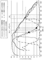
- FIG. 9 is an explanatory diagram for explaining another example of the relationship between the spectral characteristics of the dichroic film and various filters according to the present embodiment and the spectrum of light emitted from the light source device.
- the upper diagram in FIG. 9 schematically shows the spectral characteristics of the dichroic film 203, the short pass filter 211, and the band pass filter 215.
- 9 shows the spectrum of light emitted from the light source device according to this embodiment.
- the horizontal axis and the vertical axis in each of the upper diagram and the lower diagram in FIG. 9 are the same as those in the example shown in FIG.
- the same light source device as the example shown in FIG. 7 is used. Therefore, the lower diagram of FIG. 9 is the same as the lower diagram of FIG.
- the camera head 105b shown in FIG. 8 is different from the camera head 105a shown in FIG. 6 in that it does not have the notch filter 1055 and in that it has a band-pass filter 215 instead of the long-pass filter 213.
- the characteristics of the dichroic film 203 and the short pass filter 211 of the camera head 105b are the same as those of the camera head 105a. Therefore, in this description, the description will be given mainly focusing on the influence of not having the notch filter 1055 and the characteristics of the bandpass filter 215, and detailed description of the same parts as the camera head 105a will be omitted. To do.
- the band shown as the characteristic of the ICG dedicated bandpass filter schematically represents the respective wavelength bands of light transmitted through the bandpass filter 215 shown in FIG. 8 and light blocked by the bandpass filter 215. Is shown.
- the bandpass filter 215 transmits light in at least a part of the predetermined wavelength band in accordance with the characteristics of the fluorescent substance that emits fluorescence in the predetermined wavelength band in the near-infrared wavelength band. And has a characteristic of blocking light in other wavelength bands.
- the bandpass filter 215 transmits light in a wavelength band around 820 nm (for example, a wavelength band of 820 nm to 850 nm) that is a wavelength band of fluorescence emitted by the ICG, when the ICG is used. And has a characteristic of blocking light in other wavelength bands.
- the fluorescence emitted by the ICG enters the camera head 105b and then passes through the color separation prism 201b and the bandpass filter 215 to obtain a near-infrared light image.
- the image is formed on the imaging element 1052 for imaging.
- the camera head 105b does not have the notch filter 1055. Therefore, in the camera head 105b, the ICG excitation light enters the camera head 105b, is guided through the color separation prism 201b, and reaches the band-pass filter 215.
- the band-pass filter 215 is provided in the previous stage of the imaging device 1052 for imaging near-infrared light images, so that the ICG excitation light is blocked by the band-pass filter 215. With such a configuration, it is possible to observe a fluorescent image of the fluorescence emitted by the ICG from the near-infrared light image generated based on the imaging result obtained by the imaging device 1052 for imaging a near-infrared light image.
- the notch filter 1055 that blocks the excitation light that is, light having a wavelength of 405 nm
- a long pass filter may be attached to the camera head 105b. With such a configuration, it becomes possible to prevent the excitation light from entering the camera head 105b.
- FIG. 10 is an explanatory view schematically showing another example of the configuration of the camera head according to the present embodiment.
- the camera head 105 shown in FIG. 10 when the camera head 105 shown in FIG. 10 is explicitly shown, it may be referred to as “camera head 105c”.
- the camera head 105c includes a color separation prism 201c, a first visible light image capturing image sensor 1051a, a second visible light image capturing image sensor 1051b, and a near infrared light image capturing image capturing.
- An element 1052 and bandpass filters 233, 235, and 237 are included.
- the color separation prism 201c separates light belonging to the visible light wavelength band and light belonging to the near-infrared wavelength band from incident light incident on the camera head 105c, and then further belongs to the visible light wavelength band. Is an optical member that separates light into light belonging to a long wavelength band including an R component and light belonging to a short wavelength band including a G component and a B component.
- the color separation prism 201c corresponds to another example of the branching optical system 201 illustrated in FIG. Specifically, dichroic films 223 and 225 are provided inside the color separation prism 201c.
- the dichroic film 223 is a dichroic film for separating light belonging to the visible light wavelength band and light belonging to the near-infrared wavelength band.
- the dichroic film 225 converts the light belonging to the visible light wavelength band into light belonging to the wavelength band on the long wavelength side including the R component and light belonging to the wavelength band on the short wavelength side including the G component and the B component. It is a dichroic membrane for separation.
- the first prism 227 and the second prism 229 are joined together via the dichroic film 223, and the second prism 229 and the third prism 229 are joined together.
- the prism 231 is a prism joined to each other via the dichroic film 225. That is, a dichroic film 223 is provided at the interface between the first prism 227 and the second prism 229. A dichroic film 225 is provided at the interface between the second prism 229 and the third prism 231.
- the dichroic film 223 includes incident light that is incident on the color separation prism 201c and includes light that belongs to the visible light wavelength band and light that belongs to the near-infrared wavelength band. It is an optical film that separates light belonging to a wavelength band. Specifically, the dichroic film 223 has characteristics of transmitting light belonging to the visible light wavelength band and reflecting light belonging to the near-infrared wavelength band.
- the dichroic film 225 includes light belonging to the visible wavelength band transmitted through the dichroic film 223, light belonging to the wavelength band on the long wavelength side including the R component, and wavelength band on the short wavelength side including the G component and the B component. It is an optical film which isolate
- the dichroic film 225 has a characteristic of reflecting light belonging to the wavelength band on the long wavelength side including the R component and transmitting light belonging to the wavelength band on the short wavelength side including the G component and the B component. .
- the dichroic film 225 transmits light belonging to the wavelength band on the long wavelength side including the R component and reflects light belonging to the wavelength band on the short wavelength side including the G component and the B component. You may have.
- the first prism 227 receives near-infrared light into which light belonging to the visible wavelength band and light belonging to the near-infrared wavelength band (that is, incident light) are incident and light belonging to the near-infrared wavelength band is guided. It is a prism that functions as an optical path.
- the second prism 229 is a prism that functions as an optical path through which light belonging to the visible light wavelength band is incident and light belonging to the wavelength band on the long wavelength side including the R component of the visible light wavelength band is guided. It is.
- the third prism 231 is a prism that functions as an optical path through which light belonging to the short wavelength band including the G component and the B component in the visible light wavelength band is guided.
- Incident light that has entered the first prism 227 travels straight through the first prism 227, and belongs to the visible light wavelength band and the near-infrared wavelength band by the dichroic film 223 provided obliquely on the optical axis. Separated into light.
- the reflected and separated light belonging to the near-infrared wavelength band (that is, the near-infrared ray) is totally reflected once at the position A shown in FIG. 10 and transmitted to the outside of the first prism 227. .
- membrane 223 can be closely approached.
- the installation angle of the dichroic film 223 according to the present embodiment on the optical axis is set so that the visible light total reflection condition at the position A is satisfied.
- the dichroic film 223 By disposing the dichroic film 223 in this way, even when a light beam having a bright F value is incident on the first prism 205, the spectral characteristics of the dichroic film 203 due to the difference in the incident angle between the upper light beam and the lower light beam. The change can be suppressed, and the wavelength separation can be performed with high accuracy.
- the near-infrared ray that has passed through the first prism 227 is guided to the imaging element 1052 for taking a near-infrared light image.
- a band-pass filter 233 is provided in the optical path of the light that is separated by the dichroic film 223 and forms an image on the imaging device 1052 for imaging a near-infrared light image.
- the characteristics of the band pass filter 233 are the same as those of the band pass filter 215 described with reference to FIG.
- the band-pass filter 233 transmits light in a wavelength band around 820 nm (for example, a wavelength band of 820 nm to 850 nm), which is the wavelength band of the fluorescence emitted by the ICG. It is only necessary to have a characteristic of blocking light in the wavelength band. With such a configuration, only the fluorescence of interest can be extracted from the light belonging to the near-infrared wavelength band separated by the dichroic film 214.
- the long-pass filter 213 described with reference to FIG. 6 may be provided instead of the band-pass filter 233, and in this case, a notch filter 1055 may be attached in front of the color separation prism 201c. .
- light belonging to the visible light wavelength band transmitted through the dichroic film 223 is incident on the second prism 229.
- the light belonging to the visible light wavelength band travels straight in the second prism 229 and is a long wavelength including the R component in the visible light wavelength band by the dichroic film 225 provided obliquely on the optical axis. Is separated into light belonging to the wavelength band on the side and light belonging to the wavelength band on the short wavelength side including the G component and the B component.
- the light belonging to the long wavelength band including the R component is reflected by the dichroic film 225 and guided through the second prism 229.
- the end surface of the second prism 229 opposite to the side on which the dichroic film 225 is provided is perpendicular to the optical axis. Is provided. Therefore, the light belonging to the wavelength band on the long wavelength side including the R component is transmitted to the outside of the second prism 229 while maintaining a state perpendicular to the emission surface of the second prism 229.
- the light belonging to the long wavelength band including the R component transmitted through the second prism 229 is guided to the first visible light image capturing element 1051a.
- a band pass filter 235 is provided in the optical path of the light separated by the dichroic film 225 and imaged on the first visible light image capturing device 1051a.
- the bandpass filter 235 has a characteristic of transmitting light in the wavelength band on the long wavelength side including the R component in the visible light wavelength band and blocking light in other wavelength bands.
- the bandpass filter 235 may have a characteristic of transmitting light in a wavelength band of 600 nm to 750 nm and blocking light in other wavelength bands. With such a configuration, it is possible to exclude light other than the wavelength band on the long wavelength side including the R component included in the light separated by the dichroic film 225 (that is, the light reflected by the dichroic film 225). It becomes.
- the light belonging to the short wavelength band including the G component and the B component transmitted through the dichroic film 225 is incident on the third prism 231 and travels straight inside the third prism 231.
- the end surface of the third prism 231 opposite to the side on which the dichroic film 225 is provided (in other words, the exit surface on the downstream side of the optical axis of the third prism 231) is perpendicular to the optical axis. Is provided. For this reason, light belonging to the short wavelength band including the G component and the B component is transmitted to the outside of the third prism 231 while maintaining a state perpendicular to the emission surface of the third prism 231.
- the light belonging to the short wavelength band including the G component and the B component transmitted through the third prism 231 is guided to the second visible light image capturing element 1051b.
- a band-pass filter 237 is provided in the optical path of the light separated by the dichroic film 225 and imaged on the second visible light image capturing element 1051b.
- the band-pass filter 237 has a characteristic of transmitting light in the short wavelength band including the B component and G component in the visible light wavelength band and blocking light in other wavelength bands.
- the bandpass filter 237 may have a characteristic of transmitting light in a wavelength band of 350 nm to 600 nm and blocking light in other wavelength bands.
- the material of the color separation prism 201c according to the present embodiment is not particularly limited, and a known optical glass or optical crystal is used depending on the wavelength of light guided through the color separation prism 201c. It can be used as appropriate.
- the first visible light image capturing element 1051a is provided in the subsequent stage of the color separation prism 201c and the bandpass filter 235. That is, the first visible light image pickup imaging element 1051a has a wavelength band on the long wavelength side including the R component in the visible light wavelength band that is separated by the color separation prism 201c and transmitted through the bandpass filter 235. Light forms an image.
- the fluorescence emitted by 5ALA or reserphyrin belongs to the wavelength band on the long wavelength side including the R component in the visible light wavelength band. That is, the fluorescence emitted by 5ALA or reserphyrin is also coupled to the first visible light image capturing element 1051a. From such characteristics, it is desirable that a higher-sensitivity image sensor is applied as the first visible light image capturing element 1051a. For example, an image sensor such as a CCD or CMOS without a color filter or the like. Should be applied.
- the second visible light image capturing element 1051b is provided in the subsequent stage of the color separation prism 201c and the bandpass filter 237. That is, the second visible light image pickup device 1051b is separated by the color separation prism 201c and transmitted through the bandpass filter 237 on the short wavelength side including the G component and the B component in the visible light wavelength band. Light in the wavelength band forms an image.
- an image capturing element such as a CCD or CMOS having an RGB color filter can be applied.
- the near-infrared light image pick-up element 1052 is provided after the color separation prism 201c and the bandpass filter 233. That is, the near-infrared light imaging element 1052 has light separated by the color separation prism 201c and transmitted through the bandpass filter 233, that is, a wavelength band of fluorescence emitted by a predetermined fluorescent material (for example, ICG). The light of at least a part of the wavelength band is imaged. Because of such characteristics, it is desirable that a higher-sensitivity image sensor be applied as the near-infrared light image sensor 1052, for example, an image sensor such as a CCD or CMOS without a color filter or the like. Should be applied.
- a higher-sensitivity image sensor be applied as the near-infrared light image sensor 1052, for example, an image sensor such as a CCD or CMOS without a color filter or the like. Should be applied.
- incident light is imaged via the branching optical system.
- the description has been focused on the configuration until the image is formed on the element.
- FIG. 11 is an explanatory diagram for explaining another example of the relationship between the spectral characteristics of the dichroic film and various filters according to the present embodiment and the spectrum of light emitted from the light source device.
- the upper diagram in FIG. 11 schematically shows the spectral characteristics of the dichroic film 223 and the bandpass filters 233, 235, and 237.
- the spectral characteristics of the dichroic film 225 are not shown in order to prevent the drawing from becoming complicated.
- FIG. 11 shows a spectrum of light emitted from the light source device according to the present embodiment.
- the horizontal axis and the vertical axis in each of the upper diagram and the lower diagram in FIG. 11 are the same as those in the example shown in FIG.
- the same light source device as that in the example shown in FIG. 7 is used. Therefore, the lower diagram of FIG. 11 is the same as the lower diagram of FIG.
- the graph shown as the dichroic film characteristic schematically shows the respective wavelength bands of the light reflected by the dichroic film 223 shown in FIG. 10 and the light transmitted through the dichroic film 223.
- the inside of the graph shown as the dichroic film characteristic corresponds to a component that passes through the dichroic film 223, and the outside of the graph corresponds to a component reflected by the dichroic film 223. That is, the dichroic film 223 transmits most of light in the wavelength band of 350 nm to 750 nm (for example, 90% or more) and reflects most of light in the wavelength band of more than 750 nm (for example, 90% or more). have.
- the dichroic film 225 reflects light belonging to the wavelength band on the long wavelength side including the R component out of light belonging to the visible light wavelength band, and is on the short wavelength side including the G component and the B component. Transmits light belonging to the wavelength band.
- the dichroic film 225 reflects most (eg, 90% or more) of light in the wavelength band of 600 nm to 750 nm out of light in the wavelength band of 350 nm to 750 nm, and has a wavelength of 350 nm to 600 nm. It is preferable to have a characteristic of transmitting most of the band light (for example, 90% or more).
- the graph shown as the first bandpass filter characteristic shows the respective wavelength bands of light transmitted through the bandpass filter 235 shown in FIG. 10 and light blocked by the bandpass filter 235.
- the bandpass filter 235 transmits light in a wavelength band of 600 nm to 750 nm, for example, and blocks light in other wavelength bands.
- the wavelength band on the long wavelength side including the R component is included. Light can be imaged on the first visible light image capturing element 1051a.
- the graph shown as the second bandpass filter characteristic shows the respective wavelength bands of light transmitted through the bandpass filter 237 illustrated in FIG. 10 and light blocked by the bandpass filter 237.
- the bandpass filter 237 transmits light in a wavelength band of 350 nm to 600 nm, for example, and blocks light in other wavelength bands.
- the bands indicated as the characteristics of the ICG dedicated bandpass filter are the wavelength bands of the light transmitted through the bandpass filter 233 illustrated in FIG. 8 and the light blocked by the bandpass filter 233. Is schematically shown.
- the band-pass filter 233 transmits light in at least a part of the predetermined wavelength band according to the characteristics of the fluorescent substance that emits fluorescence in the predetermined wavelength band in the near-infrared wavelength band. And has a characteristic of blocking light in other wavelength bands.
- the bandpass filter 233 transmits light in a wavelength band around 820 nm (for example, a wavelength band of 820 nm to 850 nm), which is a wavelength band of fluorescence emitted by the ICG, when the ICG is used. And has a characteristic of blocking light in other wavelength bands.
- the camera head 105c is, for example, a fluorescent image of fluorescence belonging to a near-infrared wavelength band emitted by a fluorescent substance such as ICG, or a visible light wavelength band emitted by a fluorescent substance such as 5ALA and resaphyrin. It is possible to take a fluorescent image of the fluorescence belonging to.
- the fluorescence emitted by the ICG belongs to the near-infrared wavelength band, it enters the camera head 105 c and then forms an image on the near-infrared light image capturing element 1052 via the color separation prism 201 c and the band-pass filter 233.
- the camera head 105c does not have the notch filter 1055, like the camera head 105b described with reference to FIG. Therefore, in the camera head 105c, the ICG excitation light enters the camera head 105c, is guided through the color separation prism 201c, and reaches the band-pass filter 233.
- the bandpass filter 233 is provided in the front stage of the imaging device 1052 for imaging near-infrared light images, so that the ICG excitation light is blocked by the bandpass filter 233. With such a configuration, it is possible to observe a fluorescent image of the fluorescence emitted by the ICG from the near-infrared light image generated based on the imaging result obtained by the imaging device 1052 for imaging a near-infrared light image.
- the fluorescence emitted by 5ALA belongs to the wavelength band on the long wavelength side including the R component in the visible light wavelength band. Therefore, the fluorescence emitted by 5ALA enters the camera head 105c and then forms an image on the first visible light image pickup imaging element 1051a via the color separation prism 201a and the bandpass filter 235.
- the RGB laser light source of the visible light source 1431 among the light belonging to the visible light wavelength band irradiated by the visible light source 1431 of the light source device 143.
- the fluorescence emitted by resaphyrin belongs to the wavelength band on the long wavelength side including the R component in the visible light wavelength band. Therefore, the fluorescence emitted by the resaphyrin enters the camera head 105c and then forms an image on the first visible light image capturing element 1051a via the color separation prism 201a and the bandpass filter 235. Therefore, it is possible to observe the fluorescence image of the fluorescence emitted by the resaphyrin from the visible light image generated based on the imaging result by the first visible light image capturing image sensor 1051a.
- the camera head 105c may be equipped with a notch filter 1055 that blocks light belonging to the excitation wavelength of the fluorescent material.
- the notch filter 1055 that blocks the excitation light that is, light having a wavelength of 405 nm
- a long pass filter may be attached to the camera head 105c. With such a configuration, it is possible to prevent the excitation light from entering the camera head 105c.
- the camera head 105c synthesizes images based on the imaging results of the first visible light image capturing element 1051a and the second visible light image capturing element 1051b, so that a visible light image of the imaging target is obtained. May be generated.
- the light belonging to the visible light wavelength band is converted into the light belonging to the long wavelength side including the R component and the short wavelength including the G and B components.
- the light is divided into the light beams belonging to the bands, and each image is formed on different image sensors.
- the camera head 105c for example, emits fluorescence emitted from a fluorescent material such as 5ALA or reserphyrin with respect to an image of an imaging target based on light belonging to a short wavelength band including the G component and the B component. It is possible to superimpose the fluorescent images.
- the camera head 105c is provided for each of a fluorescent fluorescent image emitted by a fluorescent material such as 5ALA or reserphyrin, and an image of an imaging target based on light belonging to a short wavelength band including the G component and the B component.
- a fluorescent fluorescent image emitted by a fluorescent material such as 5ALA or reserphyrin
- an image of an imaging target based on light belonging to a short wavelength band including the G component and the B component can be performed.
- FIG. 12 is an explanatory diagram for describing the characteristics of the camera head according to the present embodiment.
- the sensitivity characteristics for each wavelength of the imaging element applied to the camera head of an endoscope imaging system and the like, and the imaging element 2 shows an example of spectral transmission characteristics of a color filter applied to FIG.
- the horizontal axis indicates the wavelength
- the vertical axis indicates the sensitivity characteristic for each wavelength of the image sensor and the spectral transmission characteristics of various filters as relative values (%).
- an example of the sensitivity characteristic for each wavelength of the so-called CMOS sensor is shown as the sensitivity characteristic of the image sensor.
- an example of spectral transmission characteristics is shown for each of the red filter, the green filter, and the blue filter as the color filter characteristics.
- a camera head capable of capturing a visible light image of an object to be imaged
- light belonging to the visible light wavelength band forms an image in order to improve the color reproducibility of the visible light image.
- An IR cut filter that cuts infrared light may be provided in front of the image sensor.
- an example of the spectral transmission characteristic of the IR cut filter is used as a reference. Is also presented.
- the IR cut filter for example, C5000 manufactured by HOYA Corporation is used.
- 5ALA emits fluorescence in the visible light region (particularly, the R component wavelength band) around 635 nm.
- Rezaphyrin emits fluorescence in the vicinity of the wavelength band of 670 nm to 730 nm, that is, fluorescence in the visible light region (particularly, near the near infrared region) to the near infrared region. Therefore, when a fluorescent image of fluorescence emitted by 5ALA or reserphyrin is captured, the fluorescent image is captured by an imaging element on which light belonging to the visible light wavelength band is imaged.
- the IR cut filter tends to have lower transmittance in the wavelength band on the long wavelength side including the R component in the visible light wavelength band. Therefore, for example, at a wavelength position around 635 nm, which is the wavelength of fluorescence emitted by 5ALA, the transmittance of the IR cut filter is reduced to about 40%. In addition, at the wavelength position of 670 nm to 730 nm, which is the wavelength of fluorescence emitted by resaphyrin, the transmittance of the IR cut filter decreases from about 20% to about several percent.
- each fluorescent material tends to have a lower light intensity than other light such as visible light reflected by the imaging object and incident in the camera head or excitation light of the fluorescent material. For this reason, in the case of a configuration in which an IR cut filter is provided in front of the image sensor, it is difficult to clearly capture a fluorescent image of fluorescence belonging to the visible light wavelength band emitted by 5ALA or Rezaphyrin.
- an IR cut filter is provided in the front stage of the image sensor that images light belonging to the visible light wavelength band.
- a short-pass filter and a band-pass filter are provided instead. That is, in the camera head according to the present embodiment, when the fluorescence emitted by 5ALA or reserphyrin forms an image on the image sensor, the situation where the fluorescence guided to the image sensor is limited by the IR cut filter occurs. Can be prevented. Therefore, according to the camera head according to the present embodiment, it is possible to make better use of the performance of the camera head (particularly, the imaging device) even when capturing a fluorescent fluorescent image belonging to the visible light wavelength band. Therefore, a clearer fluorescent image can be taken.
- FIG. 13 is a functional block diagram illustrating a configuration example of the hardware configuration of the information processing apparatus that configures the endoscope imaging system according to the embodiment of the present disclosure.
- the information processing apparatus 900 constituting the endoscope imaging system mainly includes a CPU 901, a ROM 903, and a RAM 905.
- the information processing apparatus 900 further includes a host bus 907, a bridge 909, an external bus 911, an interface 913, an input device 915, an output device 917, a storage device 919, a drive 921, and a connection port 923. And a communication device 925.
- the CPU 901 functions as an arithmetic processing unit and a control unit, and controls all or a part of the operation in the information processing apparatus 900 according to various programs recorded in the ROM 903, the RAM 905, the storage apparatus 919, or the removable recording medium 927.
- the ROM 903 stores programs used by the CPU 901, calculation parameters, and the like.
- the RAM 905 primarily stores programs used by the CPU 901, parameters that change as appropriate during execution of the programs, and the like. These are connected to each other by a host bus 907 constituted by an internal bus such as a CPU bus.
- the host bus 907 is connected to an external bus 911 such as a PCI (Peripheral Component Interconnect / Interface) bus via a bridge 909.
- an input device 915, an output device 917, a storage device 919, a drive 921, a connection port 923, and a communication device 925 are connected to the external bus 911 via an interface 913.
- the input device 915 is an operation means operated by the user, such as a mouse, a keyboard, a touch panel, a button, a switch, a lever, and a pedal. Further, the input device 915 may be, for example, remote control means (so-called remote control) using infrared rays or other radio waves, or an external connection device such as a mobile phone or a PDA corresponding to the operation of the information processing device 900. 929 may be used. Furthermore, the input device 915 includes an input control circuit that generates an input signal based on information input by a user using the above-described operation means and outputs the input signal to the CPU 901, for example. A user of the information processing apparatus 900 can input various data and instruct a processing operation to the information processing apparatus 900 by operating the input device 915.
- the output device 917 is a device that can notify the user of the acquired information visually or audibly. Examples of such devices include CRT display devices, liquid crystal display devices, plasma display devices, EL display devices, display devices such as lamps, audio output devices such as speakers and headphones, printer devices, and the like.
- the output device 917 outputs results obtained by various processes performed by the information processing apparatus 900. Specifically, the display device displays results obtained by various processes performed by the information processing device 900 as text or images.
- the audio output device converts an audio signal composed of reproduced audio data, acoustic data, and the like into an analog signal and outputs the analog signal.
- the storage device 919 is a data storage device configured as an example of a storage unit of the information processing device 900.
- the storage device 919 includes, for example, a magnetic storage device such as an HDD (Hard Disk Drive), a semiconductor storage device, an optical storage device, or a magneto-optical storage device.
- the storage device 919 stores programs executed by the CPU 901 and various data.
- the drive 921 is a reader / writer for a recording medium, and is built in or externally attached to the information processing apparatus 900.
- the drive 921 reads information recorded on a removable recording medium 927 such as a mounted magnetic disk, optical disk, magneto-optical disk, or semiconductor memory, and outputs the information to the RAM 905.
- the drive 921 can also write a record to a removable recording medium 927 such as a magnetic disk, an optical disk, a magneto-optical disk, or a semiconductor memory that is mounted.
- the removable recording medium 927 is, for example, a DVD medium, an HD-DVD medium, a Blu-ray (registered trademark) medium, or the like.
- the removable recording medium 927 may be a compact flash (registered trademark) (CF: CompactFlash), a flash memory, an SD memory card (Secure Digital memory card), or the like. Further, the removable recording medium 927 may be, for example, an IC card (Integrated Circuit card) on which a non-contact IC chip is mounted, an electronic device, or the like.
- CF CompactFlash
- SD memory card Secure Digital memory card
- the connection port 923 is a port for directly connecting to the information processing apparatus 900.
- Examples of the connection port 923 include a USB (Universal Serial Bus) port, an IEEE 1394 port, a SCSI (Small Computer System Interface) port, and the like.
- As another example of the connection port 923 there are an RS-232C port, an optical audio terminal, an HDMI (registered trademark) (High-Definition Multimedia Interface) port, and the like.
- the communication device 925 is a communication interface configured with, for example, a communication device for connecting to a communication network (network) 931.
- the communication device 925 is, for example, a communication card for wired or wireless LAN (Local Area Network), Bluetooth (registered trademark), or WUSB (Wireless USB).
- the communication device 925 may be a router for optical communication, a router for ADSL (Asymmetric Digital Subscriber Line), a modem for various communication, or the like.
- the communication device 925 can transmit and receive signals and the like according to a predetermined protocol such as TCP / IP, for example, with the Internet or other communication devices.
- the communication network 931 connected to the communication device 925 is configured by a wired or wireless network, and may be, for example, the Internet, a home LAN, infrared communication, radio wave communication, satellite communication, or the like. .
- a computer program for realizing each function of the information processing apparatus 900 constituting the endoscope imaging system according to the present embodiment as described above can be produced and mounted on a personal computer or the like.
- a computer-readable recording medium storing such a computer program can be provided.
- the recording medium is, for example, a magnetic disk, an optical disk, a magneto-optical disk, a flash memory, or the like.
- the above computer program may be distributed via a network, for example, without using a recording medium.
- the number of computers that execute the computer program is not particularly limited.
- the computer program may be executed by a plurality of computers (for example, a plurality of servers) in cooperation with each other.
- FIG. 14 is an explanatory diagram for describing an application example of the imaging system according to an embodiment of the present disclosure, and illustrates an example of a schematic configuration of the microscope imaging system. Specifically, FIG. 14 illustrates an example in which a surgical video microscope apparatus including an arm is used as an application example in which the microscope imaging system according to an embodiment of the present disclosure is used. Yes.
- FIG. 14 schematically shows a state of treatment using a surgical video microscope apparatus.
- a doctor who is a practitioner (user) 520 uses a surgical instrument 521 such as a scalpel, a scissors, or a forceps to perform a treatment target (patient) on the treatment table 530.
- a state in which an operation is performed on 540 is illustrated.
- the treatment is a general term for various medical treatments performed on a patient who is a treatment target 540 by a doctor who is a user 520, such as surgery and examination.
- the state of the operation is illustrated as an example of the operation, but the operation using the surgical video microscope apparatus 510 is not limited to the operation, and may be various other operations. .
- a surgical video microscope apparatus 510 is provided beside the treatment table 530.
- the surgical video microscope apparatus 510 includes a base portion 511 as a base, an arm portion 512 extending from the base portion 511, and an imaging unit 515 connected to the tip of the arm portion 512 as a tip unit.
- the arm portion 512 includes a plurality of joint portions 513a, 513b, and 513c, a plurality of links 514a and 514b connected by the joint portions 513a and 513b, and an imaging unit 515 provided at the tip of the arm portion 512.
- the arm unit 512 includes three joint units 513a to 513c and two links 514a and 514b.
- the positions of the arm unit 512 and the imaging unit 515 and Considering the degree of freedom of posture, the number and shape of the joint portions 513a to 513c and the links 514a and 514b, the direction of the drive shaft of the joint portions 513a to 513c, etc. may be appropriately set so as to realize a desired degree of freedom. Good.
- the joint portions 513a to 513c have a function of connecting the links 514a and 514b to each other so as to be rotatable, and the drive of the arm portion 512 is controlled by driving the rotation of the joint portions 513a to 513c.
- the position of each constituent member of the surgical video microscope apparatus 510 means a position (coordinates) in a space defined for drive control
- the posture of each constituent member is Means the direction (angle) with respect to an arbitrary axis in the space defined for drive control.
- the driving (or driving control) of the arm unit 512 refers to driving (or driving control) of the joint units 513a to 513c and driving (or driving control) of the joint units 513a to 513c. This means that the position and posture of each component of the arm portion 512 are changed (change is controlled).
- An imaging unit 515 is connected to the tip of the arm unit 512 as a tip unit.
- the imaging unit 515 is a unit that acquires an image of an imaging target, and is, for example, a camera that can capture a moving image or a still image.
- the posture of the arm unit 512 and the imaging unit 515 is operated by the surgical video microscope apparatus 510 so that the imaging unit 515 provided at the distal end of the arm unit 512 images the state of the surgical site of the surgical target 540. And the position is controlled.
- the configuration of the imaging unit 515 connected as the tip unit to the tip of the arm unit 512 is not particularly limited.
- the imaging unit 515 is configured as a microscope that acquires an enlarged image of the imaging target.
- the imaging unit 515 may be configured to be detachable from the arm unit 512.
- the imaging unit 515 corresponding to the usage application may be appropriately connected to the tip of the arm unit 512 as a tip unit.
- the tip unit connected to the tip of the arm unit 512 is not necessarily limited to the imaging unit 515.
- a display device 550 such as a monitor or a display is installed at a position facing the user 520.
- the image of the treatment site imaged by the imaging unit 515 is displayed on the display screen of the display device 550 as an electronic image.
- the user 520 performs various treatments while viewing the electronic image of the treatment site displayed on the display screen of the display device 550.
- the imaging system for each of a plurality of types of fluorescent substances, light including at least a part of a wavelength band component of the excitation wavelength of the fluorescent substance is applied to a predetermined imaging target.
- a light source device for irradiating is provided.
- the plurality of types of fluorescent substances include fluorescent substances that emit fluorescence belonging to the near-infrared wavelength band (for example, ICG), and fluorescent substances that emit fluorescence belonging to the visible light wavelength band (for example, 5ALA, resaphyrin, fluorescein) Etc.).
- the imaging system includes an imaging device (for example, a camera head) that captures an image acquired by a predetermined optical system unit such as an endoscope unit or a microscope unit.
- the imaging apparatus includes a branching optical system (for example, color separation prisms 201a to 201c) having a dichroic film that separates light belonging to the visible light wavelength band and light belonging to the near infrared wavelength band.
- the imaging apparatus includes a first imaging element (for example, a near-infrared light image) that is provided at a subsequent stage of the branching optical system and forms an image of light belonging to the near-infrared wavelength band separated by the dichroic film.
- An imaging element for imaging 1052) and a second imaging element for example, an imaging element for imaging visible light image 1051) on which light belonging to the visible light wavelength band separated by the dichroic film is imaged.
- the imaging system captures the fluorescent image of the fluorescence belonging to the near-infrared wavelength band emitted by the ICG or the like on the first imaging element side, and 5ALA, rezaphyrin, fluorescein, etc.
- the fluorescence image of the fluorescence belonging to the visible light wavelength band emitted by is picked up on the second image sensor side.
- the imaging system according to the present embodiment has a more preferable aspect in which a fluorescent image corresponding to the fluorescent substance to be used is displayed even in a situation where a plurality of types of fluorescent substances are selectively used. It becomes possible to pick up an image.
- the imaging apparatus applied to the imaging system according to the present embodiment does not include an IR cut filter in the preceding stage of the second imaging element that images light belonging to the visible light wavelength band. Instead, a short-pass filter and a band-pass filter are provided. With such a configuration, when fluorescent light belonging to the visible light wavelength band (especially, the wavelength band on the long wavelength side) emitted by 5ALA or Rezaphyrin forms an image on the second image sensor, the light is guided to the second image sensor. It is possible to prevent the occurrence of a situation in which the fluorescent light is limited by the IR cut filter.
- the imaging system it is possible to make better use of the performance of the second imaging device (particularly, the imaging device) even when capturing a fluorescent fluorescent image belonging to the visible light wavelength band. Therefore, a clearer fluorescent image can be taken.
- the excitation wavelength of the fluorescent substance A light source device that irradiates a predetermined imaging object with light including at least a component of a wavelength band; and An imaging device that captures an image acquired by a predetermined optical system unit;
- the imaging device A branching optical system having a dichroic film for separating light belonging to the visible light wavelength band and light belonging to the near-infrared wavelength band;
- a first imaging device provided at a subsequent stage of the branching optical system and on which light belonging to the near-infrared wavelength band separated by the dichroic film is imaged;
- a second imaging element that is provided at a subsequent stage of the branching optical system and forms an image of at least a part of the light belonging to the visible light wavelength band separated by the dichroic
- the imaging device is disposed in an optical path of light that is separated by the dichroic film and forms an image on the second imaging element, and has a wavelength equal to or less than a wavelength corresponding to a boundary between a visible light wavelength band and a near-infrared wavelength band.
- the imaging system according to (1) further including a short-pass filter that transmits light including: (3) The imaging device A notch filter provided in a preceding stage of the branching optical system and blocking light in a wavelength band of at least a part of the excitation wavelength of the first fluorescent material; A long pass filter that is disposed in an optical path of light that is separated by the dichroic film and forms an image on the first image sensor, and that transmits light having a wavelength equal to or greater than the wavelength corresponding to the boundary;
- the imaging system according to (2) including: (4) The imaging device is disposed in an optical path of light separated by the dichroic film and imaged on the first imaging element, and has at least a part of a wavelength band of fluorescence emitted by the first fluorescent material.
- the imaging system according to (2) further including a bandpass filter that transmits light and blocks light in a wavelength band of at least a part of an excitation wavelength of the first fluorescent material.
- the branching optical system has at least a part of the wavelength band of the fluorescence emitted by the second fluorescent material, and the light belonging to the visible wavelength band separated by the first dichroic film that is the dichroic film.
- the second imaging element forms an image of light belonging to the first wavelength band separated by the second dichroic film out of light belonging to the visible light wavelength band separated by the first dichroic film.
- the imaging device A third imaging element that forms an image of light belonging to the second wavelength band separated by the second dichroic film out of light belonging to the visible light wavelength band previously separated by the first dichroic film; , Light in at least a part of a wavelength band of fluorescence emitted by the first fluorescent material is disposed in an optical path of light separated by the first dichroic film and imaged on the first image sensor.
- a first bandpass filter that transmits and blocks light in a wavelength band of at least a part of the excitation wavelength of the first fluorescent material;
- a second band that is disposed in an optical path of light that is separated by the second dichroic film and forms an image on the second imaging element, and that transmits light in at least a part of the first wavelength band;
- a path filter A third band disposed in an optical path of light separated by the second dichroic film and imaged on the third imaging device and transmitting light in at least a part of the second wavelength band;
- a path filter Having The imaging system according to (1).
- the first wavelength band is a wavelength band on the long wavelength side including the wavelength band of the R component in the visible light wavelength band
- the second wavelength band is a wavelength band on the short wavelength side including the wavelength band of the G component and the B component in the visible light wavelength band.
- the imaging system according to (5).
- the light source device First light that is continuously distributed in the visible light wavelength band and has a peak that is equal to or greater than a predetermined threshold at a predetermined wavelength position; A second light containing a component of at least a part of the excitation wavelength of the first fluorescent material in the near-infrared wavelength band; Irradiate, The imaging system according to any one of (1) to (6).
- the light source device A first light source unit that emits the first light having the peak at a plurality of wavelength positions; A second light source unit for irradiating the second light; Including The first light source unit corresponds to the wavelength position that is included in the wavelength band of fluorescence emitted from the second fluorescent material or located closer to the wavelength band among the plurality of wavelength positions. Configured to control the output of light The imaging system according to (7).
- the first light has the peak at a wavelength position corresponding to each of an R component, a G component, and a B component;
- the first light source unit is configured to be able to control at least an output of light corresponding to the R component of the first light.
- the imaging system according to (8).
- the optical system unit includes an endoscope unit including a lens barrel inserted into a body cavity of a subject.
- the optical system unit includes a microscope unit that acquires an enlarged image of the imaging object.
Landscapes
- Health & Medical Sciences (AREA)
- Life Sciences & Earth Sciences (AREA)
- Surgery (AREA)
- Physics & Mathematics (AREA)
- General Health & Medical Sciences (AREA)
- Nuclear Medicine, Radiotherapy & Molecular Imaging (AREA)
- Pathology (AREA)
- Animal Behavior & Ethology (AREA)
- Public Health (AREA)
- Biomedical Technology (AREA)
- Heart & Thoracic Surgery (AREA)
- Medical Informatics (AREA)
- Molecular Biology (AREA)
- Engineering & Computer Science (AREA)
- Veterinary Medicine (AREA)
- Optics & Photonics (AREA)
- Radiology & Medical Imaging (AREA)
- Biophysics (AREA)
- General Physics & Mathematics (AREA)
- Chemical & Material Sciences (AREA)
- Analytical Chemistry (AREA)
- Oral & Maxillofacial Surgery (AREA)
- Immunology (AREA)
- Biochemistry (AREA)
- Astronomy & Astrophysics (AREA)
- Gynecology & Obstetrics (AREA)
- Endoscopes (AREA)
- Investigating, Analyzing Materials By Fluorescence Or Luminescence (AREA)
- Instruments For Viewing The Inside Of Hollow Bodies (AREA)
- Microscoopes, Condenser (AREA)
Priority Applications (5)
| Application Number | Priority Date | Filing Date | Title |
|---|---|---|---|
| US16/324,675 US11221296B2 (en) | 2016-08-19 | 2017-07-05 | Imaging system |
| DE112017004154.6T DE112017004154T5 (de) | 2016-08-19 | 2017-07-05 | Bildgebungssystem |
| US17/555,515 US11788966B2 (en) | 2016-08-19 | 2021-12-20 | Imaging system |
| US18/370,450 US12169175B2 (en) | 2016-08-19 | 2023-09-20 | Imaging system |
| US18/945,604 US20250067673A1 (en) | 2016-08-19 | 2024-11-13 | Imaging system |
Applications Claiming Priority (2)
| Application Number | Priority Date | Filing Date | Title |
|---|---|---|---|
| JP2016-161544 | 2016-08-19 | ||
| JP2016161544A JP2018027272A (ja) | 2016-08-19 | 2016-08-19 | 撮像システム |
Related Child Applications (2)
| Application Number | Title | Priority Date | Filing Date |
|---|---|---|---|
| US16/324,675 A-371-Of-International US11221296B2 (en) | 2016-08-19 | 2017-07-05 | Imaging system |
| US17/555,515 Continuation US11788966B2 (en) | 2016-08-19 | 2021-12-20 | Imaging system |
Publications (1)
| Publication Number | Publication Date |
|---|---|
| WO2018034075A1 true WO2018034075A1 (ja) | 2018-02-22 |
Family
ID=61197371
Family Applications (1)
| Application Number | Title | Priority Date | Filing Date |
|---|---|---|---|
| PCT/JP2017/024582 Ceased WO2018034075A1 (ja) | 2016-08-19 | 2017-07-05 | 撮像システム |
Country Status (4)
| Country | Link |
|---|---|
| US (4) | US11221296B2 (enExample) |
| JP (1) | JP2018027272A (enExample) |
| DE (1) | DE112017004154T5 (enExample) |
| WO (1) | WO2018034075A1 (enExample) |
Cited By (6)
| Publication number | Priority date | Publication date | Assignee | Title |
|---|---|---|---|---|
| TWI680341B (zh) * | 2019-02-27 | 2019-12-21 | 台灣彩光科技股份有限公司 | 用於投影裝置的光源模組 |
| WO2020022146A1 (ja) * | 2018-07-27 | 2020-01-30 | 京セラ株式会社 | 電磁波検出装置および情報取得システム |
| WO2020066610A1 (ja) * | 2018-09-25 | 2020-04-02 | ミズホ株式会社 | 蛍光観察カメラシステム |
| EP3744286A1 (en) * | 2019-05-27 | 2020-12-02 | Leica Instruments (Singapore) Pte. Ltd. | Microscope system and method for controlling a surgical microscope |
| US11050951B2 (en) * | 2018-10-10 | 2021-06-29 | Nanjing Nuoyuan Medical Devices Co., Ltd. | Guidance system for a near-infrared fluorescein angiography operation with a 785nm continuous wavelength light source |
| US11627870B2 (en) * | 2018-01-05 | 2023-04-18 | Boston Scientific Scimed, Inc. | Fluorophore imaging devices, systems, and methods for an endoscopic procedure |
Families Citing this family (30)
| Publication number | Priority date | Publication date | Assignee | Title |
|---|---|---|---|---|
| JP2018027272A (ja) * | 2016-08-19 | 2018-02-22 | ソニー株式会社 | 撮像システム |
| US20180140375A1 (en) * | 2016-11-23 | 2018-05-24 | Roger de la Torre | Videoscopic surgery and endoscopic surgery procedures employing oscillating images |
| JP6996518B2 (ja) * | 2017-01-16 | 2022-02-04 | ソニーグループ株式会社 | 分岐光学系、撮像装置、及び撮像システム |
| DE112019002648T5 (de) * | 2018-05-24 | 2021-04-22 | Keio University | Chirurgisches beobachtungssystem |
| DE112019004271T5 (de) * | 2018-08-31 | 2021-05-27 | Hoya Corporation | Endoskopsystem und Verfahren zum Bedienen des Endoskopsystems |
| CN112996423A (zh) | 2018-11-07 | 2021-06-18 | 索尼集团公司 | 图像获取系统和图像获取方法 |
| US12268469B2 (en) * | 2018-11-30 | 2025-04-08 | Intuitive Surgical Operations, Inc. | Medical imaging systems and methods that facilitate use of different fluorescence imaging agents |
| EP3779554B1 (en) * | 2019-08-14 | 2024-01-17 | Leica Instruments (Singapore) Pte. Ltd. | Optical beam splitter assembly, camera head, and microscope assembly |
| EP3786765A1 (en) * | 2019-08-29 | 2021-03-03 | Leica Instruments (Singapore) Pte. Ltd. | Microscope, control circuit, method and computer program for generating information on at least one inspected region of an image |
| EP3882681A1 (en) * | 2020-03-10 | 2021-09-22 | Leica Instruments (Singapore) Pte. Ltd. | A concept for a microscope system with an led-based illumination system |
| JP7287676B2 (ja) | 2020-04-17 | 2023-06-06 | i-PRO株式会社 | 3板式カメラおよび4板式カメラ |
| US11950022B1 (en) * | 2020-04-24 | 2024-04-02 | Apple Inc. | Head-mounted devices with forward facing cameras |
| CN111568549B (zh) * | 2020-05-28 | 2025-02-14 | 维景医疗科技(浙江)有限公司 | 一种具有实时成像功能的可视化系统 |
| KR20230028754A (ko) * | 2020-06-25 | 2023-03-02 | 블레이즈 바이오사이언스 인코포레이티드 | 동시 근적외선 광 및 가시 광 이미징을 위한 시스템 및 방법 |
| JP7477158B2 (ja) * | 2020-07-31 | 2024-05-01 | i-PRO株式会社 | 3板式カメラ |
| US11602267B2 (en) * | 2020-08-28 | 2023-03-14 | Karl Storz Imaging, Inc. | Endoscopic system incorporating multiple image sensors for increased resolution |
| DE102021106836A1 (de) | 2020-10-02 | 2022-04-07 | Karl Storz Se & Co. Kg | Optisches Filtersystem für ein Video-Endoskop, Anzeigesystem und Video-Endoskop |
| JP6877705B1 (ja) * | 2020-10-05 | 2021-05-26 | ニレック株式会社 | 内視鏡及び当該内視鏡に設けられた撮像部 |
| DE102020132951A1 (de) | 2020-12-10 | 2022-06-15 | Karl Storz Se & Co. Kg | Erfassung von Bildern eines medizinischen Situs in Weißlicht und Fluoreszenzlicht |
| DE102020132978A1 (de) | 2020-12-10 | 2022-06-15 | Karl Storz Se & Co. Kg | Erfassung von Bildern eines medizinischen Objekts in Weißlicht und Fluoreszenzlicht |
| DE102020132982A1 (de) | 2020-12-10 | 2022-06-15 | Karl Storz Se & Co. Kg | Erfassung von Bildern eines medizinischen Objekts in Weißlicht und Fluoreszenzlicht |
| US20220413274A1 (en) * | 2021-06-23 | 2022-12-29 | Klar Scientific, Inc. | Spectroscopic microscope with changeable optics/components |
| US20250028159A1 (en) * | 2021-11-26 | 2025-01-23 | Agency For Science, Technology And Research | Multimodal microscopy system |
| US20230240536A1 (en) * | 2022-01-28 | 2023-08-03 | Visionsense Ltd. | Endoscope camera assembly |
| US12239409B2 (en) | 2022-02-28 | 2025-03-04 | Visionsense Ltd. | Fluorescence imaging camera assembly for open surgery |
| DE102022116292A1 (de) * | 2022-06-30 | 2024-01-04 | Karl Storz Se & Co. Kg | Strahlteilungsvorrichtung für einen distalen Endabschnitt eines Endoskops, Objektivsystem und Endoskop |
| CN119855532A (zh) * | 2022-09-16 | 2025-04-18 | 索尼集团公司 | 成像装置和医学观察系统 |
| WO2024057990A1 (ja) * | 2022-09-16 | 2024-03-21 | ソニーグループ株式会社 | 撮像装置及び医療用観察システム |
| DE102023103356A1 (de) * | 2023-02-10 | 2024-08-14 | Olympus Winter & Ibe Gmbh | Medizinisches Multifarbstoff-Fluoreszenzbildgebungssystem und -verfahren |
| WO2024185435A1 (ja) * | 2023-03-03 | 2024-09-12 | ソニー・オリンパスメディカルソリューションズ株式会社 | 医療観察システム及び医療観察方法 |
Citations (6)
| Publication number | Priority date | Publication date | Assignee | Title |
|---|---|---|---|---|
| JPH08224209A (ja) * | 1995-02-23 | 1996-09-03 | Olympus Optical Co Ltd | 蛍光観察装置 |
| JPH10201707A (ja) * | 1996-11-20 | 1998-08-04 | Olympus Optical Co Ltd | 内視鏡装置 |
| JP2010082040A (ja) * | 2008-09-30 | 2010-04-15 | Fujifilm Corp | 内視鏡システム |
| JP2012088304A (ja) * | 2010-09-24 | 2012-05-10 | Shin Nippon Air Technol Co Ltd | 生物粒子評価装置及び生物粒子評価方法 |
| JP2013200209A (ja) * | 2012-03-26 | 2013-10-03 | Olympus Corp | 蛍光観察方法及び蛍光観察装置 |
| JP2016120105A (ja) * | 2014-12-25 | 2016-07-07 | ソニー株式会社 | 照明装置、照明方法及び観察装置 |
Family Cites Families (11)
| Publication number | Priority date | Publication date | Assignee | Title |
|---|---|---|---|---|
| US7179222B2 (en) | 1996-11-20 | 2007-02-20 | Olympus Corporation | Fluorescent endoscope system enabling simultaneous achievement of normal light observation based on reflected light and fluorescence observation based on light with wavelengths in infrared spectrum |
| US20020138008A1 (en) * | 2000-01-13 | 2002-09-26 | Kazuhiro Tsujita | Method and apparatus for displaying fluorescence images and method and apparatus for acquiring endoscope images |
| US20050027166A1 (en) * | 2003-06-17 | 2005-02-03 | Shinya Matsumoto | Endoscope system for fluorescent observation |
| JP2005345716A (ja) * | 2004-06-02 | 2005-12-15 | Olympus Corp | 顕微鏡 |
| WO2007106624A2 (en) | 2006-02-07 | 2007-09-20 | Novadaq Technologies Inc. | Near infrared imaging |
| DE102009024943A1 (de) | 2009-06-10 | 2010-12-16 | W.O.M. World Of Medicine Ag | Bildgebungssystem und Verfahren zur fluoreszenz-optischen Visualisierung eines Objekts |
| JP6103824B2 (ja) * | 2012-06-04 | 2017-03-29 | オリンパス株式会社 | 蛍光内視鏡装置 |
| JPWO2016072172A1 (ja) * | 2014-11-05 | 2017-04-27 | オリンパス株式会社 | 内視鏡システム |
| WO2016117071A1 (ja) * | 2015-01-22 | 2016-07-28 | オリンパス株式会社 | 撮像装置 |
| US10365218B2 (en) * | 2016-05-27 | 2019-07-30 | Verily Life Sciences Llc | Systems and methods for 4-D hyperspectral imaging |
| JP2018027272A (ja) * | 2016-08-19 | 2018-02-22 | ソニー株式会社 | 撮像システム |
-
2016
- 2016-08-19 JP JP2016161544A patent/JP2018027272A/ja active Pending
-
2017
- 2017-07-05 US US16/324,675 patent/US11221296B2/en active Active
- 2017-07-05 WO PCT/JP2017/024582 patent/WO2018034075A1/ja not_active Ceased
- 2017-07-05 DE DE112017004154.6T patent/DE112017004154T5/de active Pending
-
2021
- 2021-12-20 US US17/555,515 patent/US11788966B2/en active Active
-
2023
- 2023-09-20 US US18/370,450 patent/US12169175B2/en active Active
-
2024
- 2024-11-13 US US18/945,604 patent/US20250067673A1/en active Pending
Patent Citations (6)
| Publication number | Priority date | Publication date | Assignee | Title |
|---|---|---|---|---|
| JPH08224209A (ja) * | 1995-02-23 | 1996-09-03 | Olympus Optical Co Ltd | 蛍光観察装置 |
| JPH10201707A (ja) * | 1996-11-20 | 1998-08-04 | Olympus Optical Co Ltd | 内視鏡装置 |
| JP2010082040A (ja) * | 2008-09-30 | 2010-04-15 | Fujifilm Corp | 内視鏡システム |
| JP2012088304A (ja) * | 2010-09-24 | 2012-05-10 | Shin Nippon Air Technol Co Ltd | 生物粒子評価装置及び生物粒子評価方法 |
| JP2013200209A (ja) * | 2012-03-26 | 2013-10-03 | Olympus Corp | 蛍光観察方法及び蛍光観察装置 |
| JP2016120105A (ja) * | 2014-12-25 | 2016-07-07 | ソニー株式会社 | 照明装置、照明方法及び観察装置 |
Cited By (15)
| Publication number | Priority date | Publication date | Assignee | Title |
|---|---|---|---|---|
| US12310562B2 (en) | 2018-01-05 | 2025-05-27 | Boston Scientific Scimed, Inc. | Attachment for duodenoscope |
| US11839360B2 (en) | 2018-01-05 | 2023-12-12 | Boston Scientific Scimed, Inc. | Fluorophore imaging devices, systems, and methods for an endoscopic procedure |
| US11627870B2 (en) * | 2018-01-05 | 2023-04-18 | Boston Scientific Scimed, Inc. | Fluorophore imaging devices, systems, and methods for an endoscopic procedure |
| JP7257751B2 (ja) | 2018-07-27 | 2023-04-14 | 京セラ株式会社 | 電磁波検出装置 |
| WO2020022146A1 (ja) * | 2018-07-27 | 2020-01-30 | 京セラ株式会社 | 電磁波検出装置および情報取得システム |
| JP2020016605A (ja) * | 2018-07-27 | 2020-01-30 | 京セラ株式会社 | 電磁波検出装置および情報取得システム |
| US12248072B2 (en) | 2018-07-27 | 2025-03-11 | Kyocera Corporation | Electromagnetic wave detection apparatus and information acquisition system |
| CN112469976A (zh) * | 2018-07-27 | 2021-03-09 | 京瓷株式会社 | 电磁波检测装置以及信息获取系统 |
| JP7233744B2 (ja) | 2018-09-25 | 2023-03-07 | ミズホ株式会社 | 蛍光観察カメラシステム |
| EP3858215A4 (en) * | 2018-09-25 | 2022-06-01 | Mizuho Corporation | FLUORESCENCE OBSERVATION CAMERA SYSTEM |
| JPWO2020066610A1 (ja) * | 2018-09-25 | 2021-11-18 | ミズホ株式会社 | 蛍光観察カメラシステム |
| WO2020066610A1 (ja) * | 2018-09-25 | 2020-04-02 | ミズホ株式会社 | 蛍光観察カメラシステム |
| US11050951B2 (en) * | 2018-10-10 | 2021-06-29 | Nanjing Nuoyuan Medical Devices Co., Ltd. | Guidance system for a near-infrared fluorescein angiography operation with a 785nm continuous wavelength light source |
| TWI680341B (zh) * | 2019-02-27 | 2019-12-21 | 台灣彩光科技股份有限公司 | 用於投影裝置的光源模組 |
| EP3744286A1 (en) * | 2019-05-27 | 2020-12-02 | Leica Instruments (Singapore) Pte. Ltd. | Microscope system and method for controlling a surgical microscope |
Also Published As
| Publication number | Publication date |
|---|---|
| DE112017004154T5 (de) | 2019-05-23 |
| US20220120689A1 (en) | 2022-04-21 |
| US20250067673A1 (en) | 2025-02-27 |
| US11221296B2 (en) | 2022-01-11 |
| US20240011909A1 (en) | 2024-01-11 |
| JP2018027272A (ja) | 2018-02-22 |
| US12169175B2 (en) | 2024-12-17 |
| US20190170647A1 (en) | 2019-06-06 |
| US11788966B2 (en) | 2023-10-17 |
Similar Documents
| Publication | Publication Date | Title |
|---|---|---|
| US12169175B2 (en) | Imaging system | |
| JP6996518B2 (ja) | 分岐光学系、撮像装置、及び撮像システム | |
| JP7095693B2 (ja) | 医療用観察システム | |
| JP2012065698A (ja) | 手術支援システムおよびそれを用いた手術支援方法 | |
| CN115917394B (zh) | 医疗成像系统、医疗成像装置和操作方法 | |
| WO2018168261A1 (ja) | 制御装置、制御方法、及びプログラム | |
| WO2020008920A1 (ja) | 医療用観察システム、医療用観察装置、及び医療用観察装置の駆動方法 | |
| US12102296B2 (en) | Medical imaging system, medical imaging device, and operation method | |
| JPWO2020045014A1 (ja) | 医療システム、情報処理装置及び情報処理方法 | |
| WO2020184228A1 (ja) | 医療用画像処理装置、医療用画像処理装置の駆動方法、及び医療用観察システム | |
| JP7480779B2 (ja) | 医療用画像処理装置、医療用画像処理装置の駆動方法、医療用撮像システム、及び医療用信号取得システム | |
| US20210228061A1 (en) | Medical observation system, medical observation apparatus, and drive method of medical observation apparatus | |
| CN110785110A (zh) | 医学成像系统、方法以及计算机程序产品 |
Legal Events
| Date | Code | Title | Description |
|---|---|---|---|
| 121 | Ep: the epo has been informed by wipo that ep was designated in this application |
Ref document number: 17841303 Country of ref document: EP Kind code of ref document: A1 |
|
| 122 | Ep: pct application non-entry in european phase |
Ref document number: 17841303 Country of ref document: EP Kind code of ref document: A1 |