WO2018030441A1 - 多孔質体および遮音材 - Google Patents
多孔質体および遮音材 Download PDFInfo
- Publication number
- WO2018030441A1 WO2018030441A1 PCT/JP2017/028850 JP2017028850W WO2018030441A1 WO 2018030441 A1 WO2018030441 A1 WO 2018030441A1 JP 2017028850 W JP2017028850 W JP 2017028850W WO 2018030441 A1 WO2018030441 A1 WO 2018030441A1
- Authority
- WO
- WIPO (PCT)
- Prior art keywords
- porous body
- particles
- sound
- surface side
- concentration
- Prior art date
- Legal status (The legal status is an assumption and is not a legal conclusion. Google has not performed a legal analysis and makes no representation as to the accuracy of the status listed.)
- Ceased
Links
Images



Classifications
-
- C—CHEMISTRY; METALLURGY
- C08—ORGANIC MACROMOLECULAR COMPOUNDS; THEIR PREPARATION OR CHEMICAL WORKING-UP; COMPOSITIONS BASED THEREON
- C08J—WORKING-UP; GENERAL PROCESSES OF COMPOUNDING; AFTER-TREATMENT NOT COVERED BY SUBCLASSES C08B, C08C, C08F, C08G or C08H
- C08J9/00—Working-up of macromolecular substances to porous or cellular articles or materials; After-treatment thereof
- C08J9/28—Working-up of macromolecular substances to porous or cellular articles or materials; After-treatment thereof by elimination of a liquid phase from a macromolecular composition or article, e.g. drying of coagulum
-
- G—PHYSICS
- G10—MUSICAL INSTRUMENTS; ACOUSTICS
- G10K—SOUND-PRODUCING DEVICES; METHODS OR DEVICES FOR PROTECTING AGAINST, OR FOR DAMPING, NOISE OR OTHER ACOUSTIC WAVES IN GENERAL; ACOUSTICS NOT OTHERWISE PROVIDED FOR
- G10K11/00—Methods or devices for transmitting, conducting or directing sound in general; Methods or devices for protecting against, or for damping, noise or other acoustic waves in general
- G10K11/16—Methods or devices for protecting against, or for damping, noise or other acoustic waves in general
Definitions
- the present invention relates to a porous body and a sound insulating material provided with the porous body.
- the sound insulating property (transmission loss) of the sound insulating material follows a mass rule that is proportional to the logarithm of the sound frequency and the surface density of the sound insulating material. That is, there is a common sense that the heavier the sound insulation material, the better the sound insulation. Therefore, a plate made of a metal such as lead or iron is used as a normal sound insulating material.
- Japanese Laid-Open Patent Publication No. 9-226035 Japanese Unexamined Patent Publication No. 2006-89555 Japanese Unexamined Patent Publication No. 2006-335917 Japanese Unexamined Patent Publication No. 8-245819
- An object of the present invention is to provide a porous body and a sound insulating material that are lightweight and have excellent sound insulating properties.
- the porous body of the present invention is a porous body having continuous pores; the porous body has a first surface and a second surface opposite to the first surface; The mass includes a plurality of particles; the concentration of the particles on the second surface side is three times or more the concentration of the particles on the first surface side.
- the sound insulating material of the present invention includes the porous body.
- the porous body and sound insulation material of the present invention are lightweight and have excellent sound insulation properties.
- FIG. 1 is a schematic cross-sectional view showing an example of the porous body of the present invention.
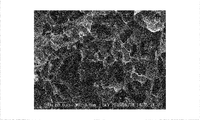
- FIG. 2 is an electron micrograph of a surface sliced from the first surface at a depth of 150 ⁇ m with respect to the porous body of Example 1.
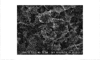
- FIG. 3 is an electron micrograph of a surface sliced at half the thickness of the porous body of Example 1.
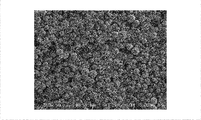
- FIG. 4 is an electron micrograph of the second surface of the porous body of Example 1.
- FIG. 5 is an electron micrograph of the surface of the porous body of Comparative Example 1 sliced from the first surface at a depth of 150 ⁇ m.
- FIG. 6 is an electron micrograph of a surface sliced at half the thickness of the porous body of Comparative Example 1.
- FIG. 7 is an electron micrograph of the second surface of the porous body of Comparative Example 1.
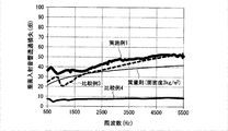
- FIG. 8 is a graph showing normal incident sound transmission loss versus frequency for the porous body of Example 1 and the sound absorbing materials of Comparative Examples 3 and 4.
- Porcity refers to pores formed by voids formed in a porous body. “Continuous pores” refers to pores in which pores communicate with each other. “Xerogel” is the definition of terminology related to the structure and process of sols, gels, stitches, and inorganic / organic composite materials (IUPAC) Inorganic Chemistry Subcommittee and Polymer Subcommittee Polymer Terminology Subcommittee ( "IUPAC Recommendation 2007)” means "a gel composed of an open network formed by removing a swelling agent from a gel.” Classification of airgel with swelling agent (solvent) removed by supercritical drying, xerogel with swelling agent (solvent) removed by normal evaporation drying, and cryogel with swelling agent (solvent) removed by freeze drying Although there is a law, in the present specification and claims, these are collectively referred to as xerogel.
- the “matrix” refers to a base material excluding particles among materials forming a skeleton (open network) of a porous body.
- the “concentration of particles on the first surface side” is the number of particles existing in an arbitrary region of 150 ⁇ m ⁇ 150 ⁇ m when the first surface is observed with an electron microscope.
- “Concentration of particles on the second surface side” is the number of particles existing in an arbitrary region of 150 ⁇ m ⁇ 150 ⁇ m when the second surface is observed with an electron microscope.
- the skin layer mentioned later may be formed in any one or both of the 1st surface and 2nd surface of a porous body.
- the surface from which the skin layer is removed is measured. That is, “the concentration of particles on the first surface side” when the skin layer is formed on the first surface is obtained by observing the surface obtained by slicing the porous body with a depth of 150 ⁇ m from the first surface with an electron microscope. The number of particles existing in an arbitrary region of 150 ⁇ m ⁇ 150 ⁇ m.
- the “particle concentration on the second surface side” is the surface obtained by slicing the porous body with a depth of 150 ⁇ m from the second surface.
- the “average pore diameter” is a value obtained by measuring the pore diameter of continuous pores by a mercury intrusion method using a mercury porosimeter and averaging the output pore diameters.
- the porous body of the present invention is a porous body having continuous pores, and has a first surface and a second surface opposite to the first surface.
- the porous body of the present invention includes a plurality of particles, and the concentration of particles on the second surface side is three times or more than the concentration of particles on the first surface side.
- FIG. 1 is a schematic cross-sectional view showing an example of the porous body of the present invention.
- the porous body 10 has continuous pores 12.
- the porous body 10 includes a plurality of particles 14.
- the continuous pores 12 are hardly opened on the first surface A side and are opened on the second surface B side.
- the particles 14 are unevenly distributed on the second surface B side rather than the first surface A side.
- a part of the particles 14 is completely buried in the skeleton 16 serving as the partition walls of the continuous pores 12, and the remaining part of the particles 14 is movably present in the continuous pores 12 or the skeleton 16. Are partially buried in the continuous pores 12.
- the average pore diameter of the continuous pores is preferably 10 to 150 ⁇ m, more preferably 30 to 120 ⁇ m, further preferably 50 to 100 ⁇ m, and particularly preferably 55 to 70 ⁇ m. If the average pore diameter of the continuous pores is equal to or greater than the lower limit of the above range, the viscosity resistance of the air in the pores does not become too high and the air easily moves, so that the sound insulation of the porous body and the sound insulation material is further improved. If the average pore diameter of the continuous pores is less than or equal to the upper limit of the above range, the surface area of the partition walls of the continuous pores in contact with the air is sufficiently increased, so that friction between the air (sound) and the partition occurs efficiently. Therefore, the sound insulation of the porous body and the sound insulation material is further improved.
- the average porosity of the porous body is preferably 50 to 98%, more preferably 55 to 90%, still more preferably 60 to 85%, and particularly preferably 65 to 80%. If the average porosity of the porous body is equal to or greater than the lower limit of the above range, the surface area of the partition walls of the continuous pores in contact with air will be sufficiently large, so that friction between the air (sound) and the partition occurs efficiently. Therefore, the sound insulation of the porous body and the sound insulation material is further improved. Further, the specific gravity of the porous body is reduced, and the porous body and the sound insulating material are further reduced in weight. If the average pore diameter of the porous body is less than or equal to the upper limit of the above range, the mechanical strength becomes sufficiently large, and therefore handling can be performed without crushing or breaking the porous body in production and use. Moreover, it is excellent in mass productivity.
- particles examples include fillers.
- the filler may be an inorganic filler or an organic filler. They may be used alone or in combination with several kinds of fillers.
- Examples of the inorganic filler include inorganic particles, flaky clay, and inorganic fiber materials.
- Examples of inorganic particles include silica particles, zirconia particles, titania particles, alumina particles, and zinc oxide particles.
- silica particles are preferable from the viewpoints of a wide variety of particle sizes, structures, and shapes.
- silica particles examples include silica gel particles, non-porous silica particles, porous silica particles, scaly silica particles, hollow silica particles, fumed silica particles, and the like.
- the shape of the silica particles is preferably spherical from the viewpoint of dispersibility.
- flaky clay examples include mica, montmorillonite, and mica. Glass fiber etc. are mentioned as an inorganic fiber material.
- Examples of the organic filler include resin particles and organic fiber materials.
- the concentration of the particles on the second surface side is 3 times or more of the concentration of the particles on the first surface side, preferably 4 times or more, more preferably 5 times or more, and further preferably 6 times or more. If the concentration of the particles on the second surface side is 3 times or more, the second surface side becomes rigid and the rigidity of the entire porous body is increased. Since sound is reflected due to the rigidity of the entire porous body, the sound insulation of the porous body and the sound insulating material is excellent.
- the concentration of the particles on the second surface side is preferably 100 times or less, more preferably 50 times or less, still more preferably 20 times or less, particularly preferably 10 times or less, and 7 times that of the first surface side. The following are most preferred. When the concentration of the particles on the second surface side is 100 times or less, the porous body can be bent, and the porous body can easily follow a complicated shape.
- the content of particles in the entire porous body is preferably 10 to 300 parts by weight, more preferably 30 to 200 parts by weight, and more preferably 50 to 100 parts by weight with respect to 100 parts by weight of the matrix forming the skeleton of the porous body. Part is more preferred.
- the particle content is at least the lower limit of the above range, the sound insulating properties of the porous body and the sound insulating material are further improved. If the content of the particles is not more than the upper limit of the above range, the porous body and the sound insulating material are further lightened.
- the porous body is excellent in flexibility, and the porous body can easily follow a complicated shape.
- At least a part of the particles are movably present in the continuous pores, or are partially buried in the skeleton and exist in the continuous pores.
- the presence of at least a part of the particles in the continuous pores makes the pores in the porous body have a complicated shape compared to the case without particles, and the friction between the air (sound) and the particles occurs more efficiently. . Therefore, the sound insulation of the porous body and the sound insulation material is further improved.
- At least a part of the particles present in the continuous pores are movably present in the continuous pores.
- the kinetic energy of the sound is converted into thermal energy and absorbed by the friction caused by the movement of the particles in the continuous pores. Therefore, the sound insulation of the porous body and the sound insulation material is further improved.
- the skeleton of the porous body is a portion that becomes a partition wall of continuous pores.
- the skeleton of the porous body may form a so-called skin layer in which one or both of the first surface and the second surface have few or no continuous pores.
- the skeleton of the porous body includes a matrix which is a base material and particles embedded in a dispersed state in the matrix.
- the matrix may be an organic matrix or an inorganic matrix.
- an organic matrix is preferable because it is lightweight, the porous body is excellent in flexibility, and the porous body can easily follow a complicated shape.
- the organic matrix examples include a cured product of curable resin, nano organic fiber, and thermoplastic resin.
- a cured product of a curable resin is preferable because a porous body in which the concentration of particles on the second surface side is sufficiently higher than the concentration of particles on the first surface side can be easily produced.
- a cured product of the curable resin As a cured product of the curable resin, a cured product of a photocurable resin containing at least one selected from the group consisting of a photocurable monomer, a photocurable oligomer, and a photocurable polymer; a thermosetting monomer, a heat Cured thermosetting resin containing at least one selected from the group consisting of curable oligomers and thermosetting polymers; and those obtained by polycondensing monomers such as melamine resin, phenol resin, polyimide, etc. It is done.
- nano organic fibers include celluloses, bio-based nano fibers, and synthetic resin-based nano fibers.
- celluloses include cellulose obtained from wood, bacterial cellulose synthesized by bacteria, and the like.
- bio-based nanofibers include xanthan and chitosan.
- synthetic resin-based nanofiber include a nanofiber obtained by electrospinning a synthetic resin.
- thermoplastic resin examples include various types such as polymethyl methacrylate (PMMA), polystyrene, and polyester.
- An example of the inorganic matrix is a metal oxide.
- the metal oxide include silica, alumina, titania, zirconia and the like.
- the thickness of the porous body is preferably 0.5 to 50 mm, more preferably 1 to 30 mm, and even more preferably 5 to 20 mm. If the thickness of the porous body is not less than the lower limit of the above range, the sound insulation properties of the porous body and the sound insulation material are further improved. When the thickness of the porous body is equal to or less than the upper limit of the above range, the porous body and the sound insulating material are further reduced in weight. Moreover, the porous body is excellent in flexibility, and the porous body can easily follow a complicated shape.
- porous body type examples of the porous body having continuous pores include the following.
- a xerogel formed by removing the solvent from the gel.
- the concentration of the particles on the second surface side is sufficiently higher than the concentration of the particles on the first surface side; the average pore diameter of the continuous pores is sufficiently small; and the average porosity of the porous body
- xerogel is preferred because it can easily and inexpensively produce a sufficiently high porous body and is lightweight.
- xerogel is a porous body formed by replacing a solvent contained in a gel with a gas, and has a three-dimensional fine porous structure in which continuous pores exist between network skeletons.
- Xerogel includes aerogels and cryogels.
- Examples of the matrix forming the skeleton of the xerogel include the same ones as the matrix in the porous body described above, and the preferred forms are also the same.
- Examples of the particles contained in the xerogel include the same particles as those in the porous body described above, and preferred forms are also the same.
- the xerogel examples include a polymer xerogel whose matrix is a cured product of a curable resin; a cellulose xerogel whose matrix is a cellulose; a PMMA xerogel whose matrix is a thermoplastic resin; and a silica xerogel whose matrix is silica.
- polymer xerogel or cellulose xerogel is preferable, and polymer xerogel is more preferable because it is lightweight and excellent in flexibility and easily follows a complicated shape of the porous body.
- Step (IV) A step of obtaining a xerogel by drying the organogel after the step (II) or the step (III).
- step (I) the particles contained in the dispersion settle downward by allowing the dispersion to stand still. Therefore, in the step (II), a gel in which the concentration of the particles on the second surface side is sufficiently higher than the concentration of the particles on the first surface side is obtained.
- the standing time is appropriately determined according to the viscosity of the dispersion, the specific gravity of the particles, etc. so that the magnification of the concentration of the particles on the second surface side with respect to the concentration of the particles on the first surface side becomes the target magnification. do it.
- step (II) gelation may be performed by a known method according to the type of matrix or its precursor.
- step (III) water in the hydrogel may be replaced with an organic solvent by a known method.
- the matrix is a thermoplastic resin
- the particles are dispersed and cooled to obtain an organogel, and then dried. By doing so, xerogel can be obtained.
- Examples of the method for drying the organogel in the step (IV) include an atmospheric pressure drying method, a freeze drying method (freeze drying), a subcritical drying method, a supercritical drying method, and the like.
- a drying method a freeze-drying method is preferable because it causes less gel breakage and pore collapse during drying and is suitable for mass production.
- the freeze-drying method is a method in which after the organogel is frozen, the frozen gel is vacuum-dried.
- t-butanol, cyclohexane, a fluorinated solvent and the like are preferable as an organic solvent contained in the organogel in terms of mass production because no special equipment is required.
- the supercritical drying method is a method of drying an organogel in a supercritical atmosphere.
- a supercritical state such as carbon dioxide, methanol, or ethanol is used.
- the supercritical drying is preferably performed by bringing supercritical carbon dioxide into contact with the organogel under conditions of a temperature of 35 to 60 ° C. and a pressure of 7.4 to 30 MPa, for example.
- the organic solvent contained in the organogel is preferably an alcohol (methanol, ethanol, isopropanol, etc.).
- Step ( ⁇ -I) A step in which a dispersion liquid in which particles are dispersed in a solution containing a photocurable resin, a photoinitiator, and an organic solvent is poured into a mold and allowed to stand.
- Step ( ⁇ -II) A step of obtaining a polymer organogel by irradiating the dispersion with light after the step ( ⁇ -I) to gel the dispersion.
- Step ( ⁇ -IV) A step of lyophilizing the polymer organogel after the step ( ⁇ -II) to obtain a polymer xerogel.
- a specific method for producing cellulose xerogel includes, for example, a method having the following steps.
- Step ( ⁇ -I) A step of pouring a dispersion in which particles are dispersed in an aqueous dispersion of cellulose nanofibers into a mold and allowing to stand.
- Step ( ⁇ -II) A step in which after the step ( ⁇ -I), an acid is added to the dispersion to gel the dispersion to obtain a cellulose hydrogel.
- Step ( ⁇ -III) A step of replacing the water in the cellulose hydrogel with alcohol after the step ( ⁇ -II) to obtain a cellulose organogel.
- Step ( ⁇ -IV) A step of obtaining cellulose xerogel by freeze-drying cellulose organogel after step ( ⁇ -III).
- Step ( ⁇ -III) A step of replacing the water in the silica hydrogel with alcohol after the step ( ⁇ -II) to obtain a silica organogel.
- the porous body of the present invention is a porous body having continuous pores; has a first surface and a second surface opposite to the first surface; includes a plurality of particles; As long as the concentration of the particles on the surface side is three or more times the concentration of the particles on the first surface side, it is not limited to the illustrated example.
- the porous body of the present invention may have only particles completely or partially embedded in the skeleton of the porous body, and may have no particles that are movably present in the continuous pores; It may have only particles that are movably present in the continuous pores, and may not have particles that are completely or partially embedded in the skeleton of the porous body.
- the porous body of the present invention preferably has a normal incident sound transmission loss at 100 Hz in accordance with ASTM E2611-09 of 25 dB or more in the sound perpendicularly incident from the first surface side.
- the normal incident sound transmission loss at 100 Hz is 25 dB or more, for example, transmission of engine sound of a bus or truck can be suppressed.
- the normal incident sound transmission loss at 100 Hz is more preferably 30 dB or more.
- the porous body of the present invention preferably has a normal incident sound transmission loss of 500 Hz or more in conformity with ASTM E2611-09 in a sound perpendicularly incident from the first surface side. If the normal incident sound transmission loss at 500 Hz is 30 dB or more, for example, transmission of road noise of an automobile can be suppressed.
- the normal incident sound transmission loss at 500 Hz is more preferably 35 dB or more, further preferably 40 dB or more, and particularly preferably 45 dB or more.
- the porous body of the present invention preferably has a normal incident sound transmission loss at 1000 Hz in accordance with ASTM E2611-09 of 30 dB or more in the sound perpendicularly incident from the first surface side. If the normal incident sound transmission loss of 1000 Hz is 30 dB or more, for example, the transmission of wind noise of an automobile can be suppressed.
- the normal incident sound transmission loss at 1000 Hz is more preferably 35 dB or more, further preferably 40 dB or more, and particularly preferably 45 dB or more.
- the porous body of the present invention described above Since the porous body of the present invention described above has continuous pores, it is lightweight. Moreover, since it has continuous pores, friction between air (sound) and the partition walls of the continuous pores occurs efficiently. In addition, since the concentration of the particles on the second surface side includes a plurality of particles is three times or more than the concentration of the particles on the first surface side, the second surface side becomes rigid, and the entire porous body Increases rigidity. Due to the synergistic effect of sound absorption due to efficient friction between the air and the partition walls of the continuous pores and sound reflection due to the rigidity of the entire porous body, the sound insulation of the porous body is reduced. improves.
- the sound insulating material of the present invention includes the porous body of the present invention.
- the sound insulating material of the present invention may be composed only of the porous body of the present invention; it may be a laminate composed of the porous body of the present invention and other layers; A frame-like frame that supports the body may be provided on the periphery.
- Examples of other layers include a non-porous film layer, a layer made of a known sound absorbing material, and a layer made of a known sound insulating material.
- a non-porous film layer is preferable because the sound insulation of the sound insulation material is further excellent.
- a flexible film such as a polyvinyl butyral film or a soft polyvinyl chloride film is preferable because the sound insulating property of the sound insulating material is further improved.
- a non-porous film layer is adjacent to either the first surface or the second surface of the porous body because the sound insulating property of the sound insulating material is further improved.
- a non-porous film layer provided adjacent to both the first surface and the second surface of the porous body is more preferable.
- the sound insulating material of the present invention described above is light and has the porous body of the present invention having excellent sound insulating properties, it is lightweight and has excellent sound insulating properties.
- the average pore size of the continuous pores in the porous body is determined by measuring the pore size of the continuous pores by the mercury intrusion method using a mercury porosimeter (manufactured by Kantachrome Instruments, Poremster), and averaging the output pore sizes. Asked.
- Example 1 10 g of urethane acrylate (manufactured by Shin-Nakamura Chemical Co., Ltd., UA-160TM), 10 g of polyethylene glycol # 400 diacrylate (manufactured by Shin-Nakamura Chemical Co., Ltd., A-400) and 5 g of dipentaerythritol hexaacrylate as a photocurable resin (Manufactured by Shin-Nakamura Chemical Co., Ltd., A-DPH) and 1.3 g of ⁇ -ketoglutaric acid as a photoinitiator were dissolved in 475 g of t-butanol. To this solution, 25 g of spherical non-porous silica particles (manufactured by AGC S-Tech, Sunsphere NP-200, average particle size: 20 ⁇ m) were added and dispersed uniformly.
- the frozen gel is taken out from the container, vacuum dried at 40 ° C. for 24 hours with a freeze dryer, has a skin layer on the first surface side, and has no skin layer on the second surface side, thickness: 10 mm
- a polymer xerogel having a surface density of 3 kg / m 2 was obtained.
- the average pore diameter and average porosity are measured, the content of the particles with respect to 100 parts by mass of the matrix is determined, and the magnification of the concentration of the particles on the second surface side with respect to the concentration of the particles on the first surface side is determined.
- the normal incidence sound transmission loss was measured. The results are shown in Table 1 and FIG. Further, FIG. 2 shows an electron micrograph of a surface sliced at a depth of 150 ⁇ m from the first surface, and FIG. 3 shows an electron micrograph of a surface sliced at a depth of half the thickness. The electron micrograph of is shown in FIG.
- Example 2 10 g of urethane acrylate (manufactured by Shin-Nakamura Chemical Co., Ltd., UA-160TM), 10 g of polyethylene glycol # 400 diacrylate (manufactured by Shin-Nakamura Chemical Co., Ltd., A-400) and 5 g of trimethylolpropane triacrylate as a photocurable resin (Manufactured by Shin-Nakamura Chemical Co., Ltd., A-TMPT) and 1.3 g of 1-hydroxycyclohexyl phenyl ketone (BASF, Irgacure (registered trademark) 184) as a photoinitiator were dissolved in 475 g of t-butanol. It was. To this solution, 20 g of spherical non-porous silica particles (manufactured by AGC S-Tech, Sunsphere NP-200, average particle size: 20 ⁇ m) were added and dispersed uniformly.
- BASF
- a skin layer is provided on the first surface side and a skin layer is provided on the second surface side in the same manner as in Example 1 except that the dispersion liquid of Example 2 is used instead of the dispersion liquid of Example 1.
- a polymer xerogel having a thickness of 10 mm was obtained.
- the average pore diameter and average porosity are measured, the content of the particles with respect to 100 parts by mass of the matrix is determined, and the magnification of the concentration of the particles on the second surface side with respect to the concentration of the particles on the first surface side is determined.
- the normal incidence sound transmission loss was measured. The results are shown in Table 1.
- Example 3 A dry weight equivalent of 6 g of undried sulfite bleached softwood pulp, 0.075 g 2,2,6,6-tetramethylpiperidine 1-oxyl (TEMPO), and 0.75 g sodium bromide in 450 mL water After the dispersion, 13% by mass of sodium hypochlorite aqueous solution was added with sodium hypochlorite so that the amount of sodium hypochlorite was 2.5 mmol with respect to 1 g of pulp to initiate the reaction. During the reaction, a 0.5 M aqueous sodium hydroxide solution was added dropwise to keep the pH at 10.
- TEMPO 2,2,6,6-tetramethylpiperidine 1-oxyl
- the reaction product is filtered through a glass filter, washed with a sufficient amount of water and filtered 10 times to impregnate water with a solid content of 25% by mass. Oxidized pulp was obtained.
- the dispersion was poured into a polypropylene circular container and allowed to stand for 1 hour. Thereafter, 1 mol / L hydrochloric acid is added to the surface (first surface) of the dispersion so that the liquid surface of the dispersion is not disturbed, and the dispersion is gelled by leaving it to stand for 20 hours. A hydrogel was obtained. About hydrogel, the solvent substitution was performed using ion-exchange water. Next, solvent substitution was performed using a mixed solvent of 25% by mass of t-butanol and 75% by mass of water. Further, the same solvent substitution was carried out by gradually increasing the fraction of t-butanol to 50 mass%, 75 mass%, and 100 mass%.
- the solvent replacement was performed by immersing the hydrogel in a sufficient amount of the replacement solvent and rotating the container at a speed of 20 rpm. Solvent replacement was performed over 24 hours for ion-exchanged water and the mixed solvent of each t-butanol fraction, and over 50 hours for 100% by mass t-butanol. Organogel was obtained by the above solvent substitution.
- the organogel was placed in a freezer at ⁇ 30 ° C. together with the container and cooled for 16 hours to freeze.
- the frozen gel is taken out from the container, vacuum-dried at 40 ° C. for 24 hours with a freeze dryer, has a skin layer on the first surface side, has no skin layer on the second surface side, and has a thickness of 10 mm.
- a xerogel was obtained. About this xerogel, the average pore diameter and the average porosity are measured, the content of the particles with respect to 100 parts by mass of the matrix is obtained, and the magnification of the concentration of the particles on the second surface side with respect to the concentration of the particles on the first surface side is determined. The normal incidence sound transmission loss was measured. The results are shown in Table 1.
- the dispersion is poured into a circular container made of polypropylene and irradiated with ultraviolet rays of 300 mW / cm 2 at an illuminance of 300 mW / cm 2 for 5 minutes, that is, an integrated light amount: 90 J / cm 2 from the surface (first surface) side of the dispersion.
- the dispersion was gelled to obtain a polymer organogel.
- a polymer xerogel having a thickness of 10 mm was obtained in the same manner as in Example 1 except that the polymer organogel of Example 2 was used instead of the polymer organogel of Example 1.
- the skin layer was formed on the first surface side, and was not formed on the second surface side.
- FIG. 5 shows an electron micrograph of a surface sliced at a depth of 150 ⁇ m from the first surface
- FIG. 6 shows an electron micrograph of a surface sliced at a depth of half the thickness. The electron micrograph of is shown in FIG.
- the dispersion was poured into a circular container made of polypropylene and quickly cooled with ice water to eliminate fluidity. Add 1 mol / L hydrochloric acid to the surface of the dispersion (first surface) so that the liquid surface of the dispersion is not disturbed, cover and let stand for 20 hours to gel the dispersion, hydrogel Got. About hydrogel, the solvent substitution was performed using ion-exchange water. Next, solvent substitution was performed using a mixed solvent of 25% by mass of t-butanol and 75% by mass of water. Further, the same solvent substitution was carried out by gradually increasing the fraction of t-butanol to 50 mass%, 75 mass%, and 100 mass%.
- the solvent replacement was performed by immersing the hydrogel in a sufficient amount of the replacement solvent and rotating the entire container at a speed of 20 rpm. Solvent replacement was performed over 24 hours for ion-exchanged water and the mixed solvent of each t-butanol fraction, and over 50 hours for 100% by mass t-butanol. Organogel was obtained by the above solvent substitution.
- the organogel was placed in a freezer at ⁇ 30 ° C. together with the container and cooled for 16 hours to freeze.
- the frozen gel was taken out from the container and vacuum dried at 40 ° C. for 24 hours with a freeze dryer to obtain a xerogel having a thickness of 10 mm.
- the skin layer was formed on the first surface side, and was not formed on the second surface side.
- the average pore diameter and the average porosity are measured, the content of the particles with respect to 100 parts by mass of the matrix is obtained, and the magnification of the concentration of the particles on the second surface side with respect to the concentration of the particles on the first surface side is determined.
- the normal incidence sound transmission loss was measured. The results are shown in Table 1.
- the porous bodies of Examples 1 to 3 have continuous pores and are excellent in sound insulation because the ratio of the concentration of the particles on the second surface side to the concentration of the particles on the first surface side is 3 times or more. It was. As shown in FIG. 8, the porous body of Example 1 was excellent in sound insulation in a wide frequency range regardless of the mass rule (surface density: 3 kg / m 2 ). In the porous bodies of Comparative Examples 1 and 2, the magnification of the concentration of the particles on the second surface side with respect to the concentration of the particles on the first surface side is less than 3 times, so that the sound insulation is compared with Examples 1 and 2. It was inferior. As shown in Comparative Example 3 in FIG.
- the porous body of the present invention is useful as a lightweight, thin sound insulating material that does not follow the mass law.
Landscapes
- Chemical & Material Sciences (AREA)
- Engineering & Computer Science (AREA)
- Materials Engineering (AREA)
- Health & Medical Sciences (AREA)
- Chemical Kinetics & Catalysis (AREA)
- Medicinal Chemistry (AREA)
- Polymers & Plastics (AREA)
- Organic Chemistry (AREA)
- Physics & Mathematics (AREA)
- Acoustics & Sound (AREA)
- Multimedia (AREA)
- Manufacture Of Porous Articles, And Recovery And Treatment Of Waste Products (AREA)
- Soundproofing, Sound Blocking, And Sound Damping (AREA)
Abstract
本発明は、軽量であり、かつ遮音性に優れる多孔質体および遮音材の提供を目的とする。本発明は、連続気孔を有する多孔質体であり、前記多孔質体は、第1の面と、前記第1の面とは反対側の第2の面とを有し、前記多孔質体は、複数の粒子を含み、前記第2の面側の前記粒子の濃度が、前記第1の面側の前記粒子の濃度の3倍以上である、多孔質体に関する。
Description
本発明は、多孔質体、および多孔質体を備えた遮音材に関する。
遮音材が緻密で均一な材料からなる場合、遮音材の遮音性(透過損失)は、音の周波数および遮音材の面密度の対数に比例するという質量則に従うとされている。すなわち、遮音材は、重ければ重いほど遮音性に優れるという常識がある。そのため、通常の遮音材としては、鉛、鉄等の金属からなる板が用いられる。
これに対して、質量則に則らない、軽量な遮音材としては、多孔質体の独立気泡または連続気孔内に粒子を移動可能に内包した、いわゆる鈴構造の遮音材が提案されている(特許文献1~4)。鈴構造の遮音材においては、音の運動エネルギが気泡内の粒子の運動による摩擦によって熱エネルギに変換されて吸収される。
しかし、従来の鈴構造の遮音材では、遮音性はいまだ不充分である。
本発明は、軽量であり、かつ遮音性に優れる多孔質体および遮音材を提供することを目的とする。
本発明は、軽量であり、かつ遮音性に優れる多孔質体および遮音材を提供することを目的とする。
本発明の多孔質体は、連続気孔を有する多孔質体であり;前記多孔質体は、第1の面と、第1の面とは反対側の第2の面とを有し;前記多孔質体は、複数の粒子を含み;前記第2の面側の前記粒子の濃度が、前記第1の面側の前記粒子の濃度の3倍以上である。
本発明の遮音材は、上記多孔質体を備える。
本発明の遮音材は、上記多孔質体を備える。
本発明の多孔質体および遮音材は、軽量であり、かつ遮音性に優れる。
以下の用語の定義は、本明細書および特許請求の範囲にわたって適用される。
「気孔」とは、多孔質体内に形成された空隙からなる孔をいう。
「連続気孔」とは、気孔間が連通した気孔をいう。
「キセロゲル」とは、国際純正応用化学連合(IUPAC)無機化学部会および高分子部会高分子用語法小委員会の「ゾル,ゲル,編目,および無機有機複合材料の構造とプロセスに関する術語の定義(IUPAC勧告2007)」によれば「ゲルから膨潤剤を除去して形成された開放網目からなるゲル。」をいう。超臨界乾燥によって膨潤剤(溶媒)を除去したものをエアロゲル、通常の蒸発乾燥によって膨潤剤(溶媒)を除去したものをキセロゲル、凍結乾燥によって膨潤剤(溶媒)を除去したものをクライオゲルとする分類法もあるが、本明細書および特許請求の範囲においては、これらをまとめてキセロゲルと称する。
「マトリックス」とは、多孔質体の骨格(開放網目)を形成する材料のうち粒子を除く母材をいう。
「第1の面側の粒子の濃度」は、第1の面を電子顕微鏡で観察したときに任意の150μm×150μmの領域に存在する粒子の数である。
「第2の面側の粒子の濃度」は、第2の面を電子顕微鏡で観察したときに任意の150μm×150μmの領域に存在する粒子の数である。
なお、多孔質体の第1の面および第2の面のいずれか一方または両方には、後述するスキン層が形成されることがある。スキン層が形成された面側の粒子については、スキン層に埋没してその数を数えることが困難である。そのため、スキン層が形成された場合は、スキン層を除去した面について測定する。すなわち、第1の面にスキン層が形成された場合の「第1の面側の粒子の濃度」は、第1の面から150μmの深さで多孔質体をスライスした面を電子顕微鏡で観察したときに任意の150μm×150μmの領域に存在する粒子の数である。また、第2の面にスキン層が形成された場合の「第2の面側の粒子の濃度」は、第2の面から150μmの深さで多孔質体をスライスした面を電子顕微鏡で観察したときに任意の150μm×150μmの領域に存在する粒子の数である。
「平均気孔径」は、水銀ポロシメータを用いた水銀圧入法によって連続気孔の気孔径を測定し、アウトプットされた気孔径を平均した値である。
「平均気孔率」は、プレス前の多孔質体の体積と、温度:100℃、圧力:50MPa、時間:10分間の条件でプレスした後の多孔質体の体積とから下式によって求めた値である。
平均気孔率(%)=100-100×(プレス後の多孔質体の体積/プレス前の多孔質体の体積)
また、“質量部”は“重量部”と同義であり、“質量%”は“重量%”と同義である。
「気孔」とは、多孔質体内に形成された空隙からなる孔をいう。
「連続気孔」とは、気孔間が連通した気孔をいう。
「キセロゲル」とは、国際純正応用化学連合(IUPAC)無機化学部会および高分子部会高分子用語法小委員会の「ゾル,ゲル,編目,および無機有機複合材料の構造とプロセスに関する術語の定義(IUPAC勧告2007)」によれば「ゲルから膨潤剤を除去して形成された開放網目からなるゲル。」をいう。超臨界乾燥によって膨潤剤(溶媒)を除去したものをエアロゲル、通常の蒸発乾燥によって膨潤剤(溶媒)を除去したものをキセロゲル、凍結乾燥によって膨潤剤(溶媒)を除去したものをクライオゲルとする分類法もあるが、本明細書および特許請求の範囲においては、これらをまとめてキセロゲルと称する。
「マトリックス」とは、多孔質体の骨格(開放網目)を形成する材料のうち粒子を除く母材をいう。
「第1の面側の粒子の濃度」は、第1の面を電子顕微鏡で観察したときに任意の150μm×150μmの領域に存在する粒子の数である。
「第2の面側の粒子の濃度」は、第2の面を電子顕微鏡で観察したときに任意の150μm×150μmの領域に存在する粒子の数である。
なお、多孔質体の第1の面および第2の面のいずれか一方または両方には、後述するスキン層が形成されることがある。スキン層が形成された面側の粒子については、スキン層に埋没してその数を数えることが困難である。そのため、スキン層が形成された場合は、スキン層を除去した面について測定する。すなわち、第1の面にスキン層が形成された場合の「第1の面側の粒子の濃度」は、第1の面から150μmの深さで多孔質体をスライスした面を電子顕微鏡で観察したときに任意の150μm×150μmの領域に存在する粒子の数である。また、第2の面にスキン層が形成された場合の「第2の面側の粒子の濃度」は、第2の面から150μmの深さで多孔質体をスライスした面を電子顕微鏡で観察したときに任意の150μm×150μmの領域に存在する粒子の数である。
「平均気孔径」は、水銀ポロシメータを用いた水銀圧入法によって連続気孔の気孔径を測定し、アウトプットされた気孔径を平均した値である。
「平均気孔率」は、プレス前の多孔質体の体積と、温度:100℃、圧力:50MPa、時間:10分間の条件でプレスした後の多孔質体の体積とから下式によって求めた値である。
平均気孔率(%)=100-100×(プレス後の多孔質体の体積/プレス前の多孔質体の体積)
また、“質量部”は“重量部”と同義であり、“質量%”は“重量%”と同義である。
<多孔質体>
本発明の多孔質体は、連続気孔を有する多孔質体であり、第1の面と、前記第1の面とは反対側の第2の面とを有する。
本発明の多孔質体は、複数の粒子を含み、第2の面側の粒子の濃度が、第1の面側の粒子の濃度の3倍以上である。
本発明の多孔質体は、連続気孔を有する多孔質体であり、第1の面と、前記第1の面とは反対側の第2の面とを有する。
本発明の多孔質体は、複数の粒子を含み、第2の面側の粒子の濃度が、第1の面側の粒子の濃度の3倍以上である。
図1は、本発明の多孔質体の一例を示す断面模式図である。
多孔質体10は、連続気孔12を有する。多孔質体10は、複数の粒子14を含む。
連続気孔12は、第1の面Aの側にはほとんど開放しておらず、第2の面Bの側には開放している。
粒子14は、第1の面Aの側よりも第2の面Bの側に偏在している。また、粒子14の一部は、連続気孔12の隔壁となる骨格16内に完全に埋没して存在しており、粒子14の残部は、連続気孔12内に移動可能に存在する、または骨格16に部分的に埋没して連続気孔12内に存在している。
多孔質体10は、連続気孔12を有する。多孔質体10は、複数の粒子14を含む。
連続気孔12は、第1の面Aの側にはほとんど開放しておらず、第2の面Bの側には開放している。
粒子14は、第1の面Aの側よりも第2の面Bの側に偏在している。また、粒子14の一部は、連続気孔12の隔壁となる骨格16内に完全に埋没して存在しており、粒子14の残部は、連続気孔12内に移動可能に存在する、または骨格16に部分的に埋没して連続気孔12内に存在している。
(連続気孔)
多孔質体において、多孔質体に存在する気孔を音波が通過する際に、空気の粘性抵抗によって音が吸収される。多孔質体が連続気孔を有することによって、音波が気孔を通じて多孔質体中を通過する距離が、気孔間が連通していない独立気孔に比べて長いため、空気(音)と連続気孔の隔壁との摩擦が効率的に起こる。そのため、連続気孔の多孔質体および遮音材は、遮音性に優れる。
多孔質体において、多孔質体に存在する気孔を音波が通過する際に、空気の粘性抵抗によって音が吸収される。多孔質体が連続気孔を有することによって、音波が気孔を通じて多孔質体中を通過する距離が、気孔間が連通していない独立気孔に比べて長いため、空気(音)と連続気孔の隔壁との摩擦が効率的に起こる。そのため、連続気孔の多孔質体および遮音材は、遮音性に優れる。
連続気孔の平均気孔径は、10~150μmが好ましく、30~120μmがより好ましく、50~100μmがさらに好ましく、55~70μmが特に好ましい。連続気孔の平均気孔径が前記範囲の下限値以上であれば、気孔中の空気の粘性抵抗が高くなりすぎず、空気が動きやすいため多孔質体および遮音材の遮音性がさらに優れる。連続気孔の平均気孔径が前記範囲の上限値以下であれば、空気と接する連続気孔の隔壁の表面積が充分に大きくなるため、空気(音)と隔壁との摩擦が効率的に起こる。そのため、多孔質体および遮音材の遮音性がさらに優れる。
多孔質体の平均気孔率は、50~98%が好ましく、55~90%がより好ましく、60~85%がさらに好ましく、65~80%が特に好ましい。多孔質体の平均気孔率が前記範囲の下限値以上であれば、空気と接する連続気孔の隔壁の表面積が充分に大きくなるため、空気(音)と隔壁との摩擦が効率的に起こる。そのため、多孔質体および遮音材の遮音性がさらに優れる。また、多孔質体の比重が小さくなり、多孔質体および遮音材がさらに軽量となる。多孔質体の平均気孔径が前記範囲の上限値以下であれば、機械強度が充分に大きくなるため、製造上、使用上において、多孔質体が潰れたり、壊れたりすることなくハンドリングができる。また、量産性に優れる。
(粒子)
粒子としては、フィラーが挙げられる。
フィラーは、無機フィラーであってもよく、有機フィラーであってもよい。それらを単体で用いてもよく、数種類のフィラーを複合して用いてもよい。
粒子としては、フィラーが挙げられる。
フィラーは、無機フィラーであってもよく、有機フィラーであってもよい。それらを単体で用いてもよく、数種類のフィラーを複合して用いてもよい。
無機フィラーとしては、無機粒子、薄片状粘土、無機繊維材料等が挙げられる。
無機粒子としては、シリカ粒子、ジルコニア粒子、チタニア粒子、アルミナ粒子、酸化亜鉛粒子等が挙げられる。無機粒子としては、粒径や構造や形状の種類が豊富である等の点から、シリカ粒子が好ましい。
無機粒子としては、シリカ粒子、ジルコニア粒子、チタニア粒子、アルミナ粒子、酸化亜鉛粒子等が挙げられる。無機粒子としては、粒径や構造や形状の種類が豊富である等の点から、シリカ粒子が好ましい。
シリカ粒子の種類としては、シリカゲル粒子、非多孔質シリカ粒子、多孔質シリカ粒子、鱗片状シリカ粒子、中空状シリカ粒子、ヒュームドシリカ粒子等が挙げられる。シリカ粒子の形状としては、分散性の点から、球状が好ましい。
薄片状粘土としては、マイカ、モンモリロナイト、雲母等が挙げられる。
無機繊維材料としては、ガラス繊維等が挙げられる。
薄片状粘土としては、マイカ、モンモリロナイト、雲母等が挙げられる。
無機繊維材料としては、ガラス繊維等が挙げられる。
有機フィラーとしては、樹脂粒子、有機繊維材料等が挙げられる。
第2の面側の粒子の濃度は、第1の面側の粒子の濃度の3倍以上であり、4倍以上が好ましく、5倍以上がより好ましく、6倍以上がさらに好ましい。第2の面側の粒子の濃度が3倍以上であれば、第2の面側が剛直になり、多孔質体全体の剛性が高くなる。多孔質体全体の剛性の高さによる音の反射のため、多孔質体および遮音材の遮音性に優れる。第2の面側の粒子の濃度は、第1の面側の粒子の濃度の100倍以下が好ましく、50倍以下がより好ましく、20倍以下がさらに好ましく、10倍以下が特に好ましく、7倍以下が最も好ましい。第2の面側の粒子の濃度が100倍以下であれば、多孔質体を曲げることができ、多孔質体を複雑な形状に追随させやすい。
多孔質体の全体における粒子の含有量は、多孔質体の骨格を形成するマトリックスの100質量部に対して、10~300質量部が好ましく、30~200質量部がより好ましく、50~100質量部がさらに好ましい。粒子の含有量が前記範囲の下限値以上であれば、多孔質体および遮音材の遮音性がさらに優れる。粒子の含有量が前記範囲の上限値以下であれば、多孔質体および遮音材がさらに軽量となる。また、多孔質体が柔軟性に優れ、多孔質体を複雑な形状に追随させやすい。
粒子の少なくとも一部は、連続気孔内に移動可能に存在する、または骨格に部分的に埋没して連続気孔内に存在することが好ましい。粒子の少なくとも一部が連続気孔内に存在することによって、粒子がない場合と比較して、多孔質体中の気孔が複雑な形状となり、空気(音)と粒子との摩擦が効率的に起こる。そのため、多孔質体および遮音材の遮音性がさらに優れる。
また、連続気孔内に存在する粒子の少なくとも一部は、連続気孔内に移動可能に存在することが好ましい。粒子の少なくとも一部が連続気孔内に移動可能に存在することによって、音の運動エネルギが連続気孔内の粒子の運動による摩擦によって熱エネルギに変換されて吸収される。そのため、多孔質体および遮音材の遮音性がさらに優れる。
(多孔質体の骨格)
多孔質体の骨格は、連続気孔の隔壁となる部分である。多孔質体の骨格は、第1の面および第2の面にいずれか一方または両方においては連続気孔がほとんどまたはまったく開放していない、いわゆるスキン層を形成することもある。
多孔質体の骨格は、母材であるマトリックスと、マトリックス中に分散した状態で埋没した粒子とを含む。
多孔質体の骨格は、連続気孔の隔壁となる部分である。多孔質体の骨格は、第1の面および第2の面にいずれか一方または両方においては連続気孔がほとんどまたはまったく開放していない、いわゆるスキン層を形成することもある。
多孔質体の骨格は、母材であるマトリックスと、マトリックス中に分散した状態で埋没した粒子とを含む。
マトリックスは、有機マトリックスであってもよく、無機マトリックスであってもよい。マトリックスとしては、軽量であり、かつ多孔質体が柔軟性に優れ、多孔質体を複雑な形状に追随させやすい点から、有機マトリックスが好ましい。
有機マトリックスとしては、硬化性樹脂の硬化物、ナノ有機繊維、熱可塑性樹脂等が挙げられる。有機マトリックスとしては、第2の面側の粒子の濃度が第1の面側の粒子の濃度よりも充分に高い多孔質体を製造しやすい点から、硬化性樹脂の硬化物が好ましい。
硬化性樹脂の硬化物としては、光硬化性モノマー、光硬化性オリゴマーおよび光硬化性ポリマーからなる群から選ばれる少なくとも1種を含む光硬化性樹脂を硬化させたもの;熱硬化性モノマー、熱硬化性オリゴマーおよび熱硬化性ポリマーからなる群から選ばれる少なくとも1種を含む熱硬化性樹脂を硬化させたもの;メラミン樹脂、フェノール樹脂、ポリイミド等のようにモノマーを重縮合させたもの等が挙げられる。
ナノ有機繊維としては、セルロース類、バイオ系ナノ繊維、合成樹脂系ナノ繊維等が挙げられる。セルロース類としては、木材から得られるセルロース、バクテリアが合成するバクテリアセルロース等が挙げられる。バイオ系ナノ繊維としては、キサン、キトサン等が挙げられる。合成樹脂系ナノ繊維としては、合成樹脂をエレクトロスピニング法でナノ繊維化したもの等が挙げられる。
熱可塑性樹脂としては、ポリメタクリル酸メチル(PMMA)、ポリスチレン、ポリエステルなどの様々な種類のものが挙げられる。
無機マトリックスとしては、金属酸化物等が挙げられる。金属酸化物としては、シリカ、アルミナ、チタニア、ジルコニア等が挙げられる。
(多孔質体の厚さ)
多孔質体の厚さは、0.5~50mmが好ましく、1~30mmがより好ましく、5~20mmがさらに好ましい。多孔質体の厚さが前記範囲の下限値以上であれば、多孔質体および遮音材の遮音性がさらに優れる。多孔質体の厚さが前記範囲の上限値以下であれば、多孔質体および遮音材がさらに軽量となる。また、多孔質体が柔軟性に優れ、多孔質体を複雑な形状に追随させやすい。
多孔質体の厚さは、0.5~50mmが好ましく、1~30mmがより好ましく、5~20mmがさらに好ましい。多孔質体の厚さが前記範囲の下限値以上であれば、多孔質体および遮音材の遮音性がさらに優れる。多孔質体の厚さが前記範囲の上限値以下であれば、多孔質体および遮音材がさらに軽量となる。また、多孔質体が柔軟性に優れ、多孔質体を複雑な形状に追随させやすい。
(多孔質体の種類)
連続気孔を有する多孔質体としては、例えば、下記のものが挙げられる。
・ゲルから溶媒を除去して形成されたキセロゲル。
・マトリックスに可溶性粒子が分散したものを形成後、可溶性粒子を溶解除去して連続気孔を形成した多孔質体。
・2種類以上のポリマーでポリマーアロイを形成し、ナノ相分離を起こした後、1種類以上のポリマーを溶解除去して連続気孔を形成した多孔質体。
・発泡によって独立気泡を形成した後、圧縮して独立気泡の壁を破壊して連続気孔を形成した多孔質体。
連続気孔を有する多孔質体としては、例えば、下記のものが挙げられる。
・ゲルから溶媒を除去して形成されたキセロゲル。
・マトリックスに可溶性粒子が分散したものを形成後、可溶性粒子を溶解除去して連続気孔を形成した多孔質体。
・2種類以上のポリマーでポリマーアロイを形成し、ナノ相分離を起こした後、1種類以上のポリマーを溶解除去して連続気孔を形成した多孔質体。
・発泡によって独立気泡を形成した後、圧縮して独立気泡の壁を破壊して連続気孔を形成した多孔質体。
多孔質体としては、第2の面側の粒子の濃度が第1の面側の粒子の濃度よりも充分に高く;連続気孔の平均気孔径が充分に小さく;かつ多孔質体の平均気孔率が充分に高い多孔質体を容易に、かつ安価に製造できる点、および軽量である点から、キセロゲルが好ましい。
(キセロゲル)
キセロゲルは、ゲル中に含まれる溶媒を気体に置換して形成された多孔質体であり、網目状の骨格の間に連続気孔が存在する三次元的な微細な多孔性の構造を有する。キセロゲルには、エアロゲルおよびクライオゲルが包含される。
キセロゲルは、ゲル中に含まれる溶媒を気体に置換して形成された多孔質体であり、網目状の骨格の間に連続気孔が存在する三次元的な微細な多孔性の構造を有する。キセロゲルには、エアロゲルおよびクライオゲルが包含される。
キセロゲルの骨格を形成するマトリックスとしては、上述した多孔質体におけるマトリックスと同様のものが挙げられ、好ましい形態も同様である。
キセロゲルに含まれる粒子としては、上述した多孔質体における粒子と同様のものが挙げられ、好ましい形態も同様である。
キセロゲルに含まれる粒子としては、上述した多孔質体における粒子と同様のものが挙げられ、好ましい形態も同様である。
キセロゲルの具体例としては、マトリックスが硬化性樹脂の硬化物であるポリマーキセロゲル;マトリックスがセルロース類であるセルロースキセロゲル;マトリックスが熱可塑性樹脂であるPMMAキセロゲル;マトリックスがシリカであるシリカキセロゲル等が挙げられる。キセロゲルとしては、軽量であり、かつ柔軟性に優れ、多孔質体を複雑な形状に追随させやすい点から、ポリマーキセロゲルまたはセルロースキセロゲルが好ましく、ポリマーキセロゲルがより好ましい。
(キセロゲルの製造方法)
キセロゲルの製造方法としては、下記の工程(I)~(IV)を有する方法が挙げられる。
工程(I):マトリックスまたはその前駆体と粒子と溶媒とを含む分散液を型に流し込み、静置する工程。
工程(II):工程(I)の後、分散液をゲル化させてヒドロゲルまたはオルガノゲルを得る工程。
工程(III):工程(II)においてヒドロゲルを得た場合は、ヒドロゲルからオルガノゲルを得る工程。
工程(IV):工程(II)または工程(III)の後、オルガノゲルを乾燥させてキセロゲルを得る工程。
キセロゲルの製造方法としては、下記の工程(I)~(IV)を有する方法が挙げられる。
工程(I):マトリックスまたはその前駆体と粒子と溶媒とを含む分散液を型に流し込み、静置する工程。
工程(II):工程(I)の後、分散液をゲル化させてヒドロゲルまたはオルガノゲルを得る工程。
工程(III):工程(II)においてヒドロゲルを得た場合は、ヒドロゲルからオルガノゲルを得る工程。
工程(IV):工程(II)または工程(III)の後、オルガノゲルを乾燥させてキセロゲルを得る工程。
工程(I)においては、分散液を静置することによって、分散液に含まれる粒子が下方に沈降する。そのため、工程(II)において第2の面側の粒子の濃度が第1の面側の粒子の濃度よりも充分に高いゲルが得られる。
静置時間は、第1の面側の粒子の濃度に対する第2の面側の粒子の濃度の倍率が目的とする倍率となるように、分散液の粘度、粒子の比重等に応じて適宜決定すればよい。
静置時間は、第1の面側の粒子の濃度に対する第2の面側の粒子の濃度の倍率が目的とする倍率となるように、分散液の粘度、粒子の比重等に応じて適宜決定すればよい。
工程(II)においては、マトリックスまたはその前駆体の種類に応じて、公知の方法でゲル化を行えばよい。
工程(III)においては、ヒドロゲル中の水を有機溶媒に公知の方法で置換すればよい。
工程(III)においては、ヒドロゲル中の水を有機溶媒に公知の方法で置換すればよい。
また、マトリックスが熱可塑性樹脂である場合には、例えば溶媒の沸点以下の温度で、溶媒に熱可塑性樹脂を溶解させた後に粒子を分散させ、冷却することでオルガノゲルを得た後に、これを乾燥することでキセロゲルを得られる。
工程(IV)におけるオルガノゲルの乾燥方法としては、常圧乾燥法、凍結乾燥法(フリーズドライ)、亜臨界乾燥法、超臨界乾燥法等が挙げられる。乾燥方法としては、乾燥時にゲル破壊や気孔潰れが少なく、また量産に向いている点から、凍結乾燥法が好ましい。
凍結乾燥法は、オルガノゲルを凍結させた後、凍結したゲルを真空乾燥させる方法である。
凍結乾燥を行う場合、オルガノゲルに含まれる有機溶媒としては、t-ブタノール、シクロヘキサン、含フッ素溶媒等が、特別な装置を必要としないため、量産面で好ましい。
凍結乾燥を行う場合、オルガノゲルに含まれる有機溶媒としては、t-ブタノール、シクロヘキサン、含フッ素溶媒等が、特別な装置を必要としないため、量産面で好ましい。
超臨界乾燥法は、オルガノゲルを超臨界雰囲気下で乾燥させる方法である。超臨界乾燥においては、二酸化炭素、メタノール、エタノール等の超臨界状態を利用する。超臨界乾燥は、例えば、温度35~60℃、圧力7.4~30MPaの条件下で超臨界二酸化炭素をオルガノゲルに接触させることによって行うことが好ましい。
超臨界乾燥を行う場合、オルガノゲルに含まれる有機溶媒としては、アルコール(メタノール、エタノール、イソプロパノール等)が好ましい。
超臨界乾燥を行う場合、オルガノゲルに含まれる有機溶媒としては、アルコール(メタノール、エタノール、イソプロパノール等)が好ましい。
(ポリマーキセロゲルの製造方法)
ポリマーキセロゲルの具体的な製造方法としては、例えば、下記の工程を有する方法が挙げられる。
工程(α-I):光硬化性樹脂と光開始剤と有機溶媒とを含む溶液に、粒子を分散させた分散液を、型に流し込み、静置する工程。
工程(α-II):工程(α-I)の後、分散液に光を照射して分散液をゲル化させてポリマーオルガノゲルを得る工程。
工程(α-IV):工程(α-II)の後、ポリマーオルガノゲルを凍結乾燥させてポリマーキセロゲルを得る工程。
ポリマーキセロゲルの具体的な製造方法としては、例えば、下記の工程を有する方法が挙げられる。
工程(α-I):光硬化性樹脂と光開始剤と有機溶媒とを含む溶液に、粒子を分散させた分散液を、型に流し込み、静置する工程。
工程(α-II):工程(α-I)の後、分散液に光を照射して分散液をゲル化させてポリマーオルガノゲルを得る工程。
工程(α-IV):工程(α-II)の後、ポリマーオルガノゲルを凍結乾燥させてポリマーキセロゲルを得る工程。
(セルロースキセロゲルの製造方法)
セルロースキセロゲルの具体的な製造方法としては、例えば、下記の工程を有する方法が挙げられる。
工程(β-I):セルロースナノファイバーの水分散液に、粒子を分散させた分散液を、型に流し込み、静置する工程。
工程(β-II):工程(β-I)の後、分散液に酸を加えて分散液をゲル化させてセルロースヒドロゲルを得る工程。
工程(β-III):工程(β-II)の後、セルロースヒドロゲル中の水をアルコールに置換してセルロースオルガノゲルを得る工程。
工程(β-IV):工程(β-III)の後、セルロースオルガノゲルを凍結乾燥させてセルロースキセロゲルを得る工程。
セルロースキセロゲルの具体的な製造方法としては、例えば、下記の工程を有する方法が挙げられる。
工程(β-I):セルロースナノファイバーの水分散液に、粒子を分散させた分散液を、型に流し込み、静置する工程。
工程(β-II):工程(β-I)の後、分散液に酸を加えて分散液をゲル化させてセルロースヒドロゲルを得る工程。
工程(β-III):工程(β-II)の後、セルロースヒドロゲル中の水をアルコールに置換してセルロースオルガノゲルを得る工程。
工程(β-IV):工程(β-III)の後、セルロースオルガノゲルを凍結乾燥させてセルロースキセロゲルを得る工程。
(シリカキセロゲルの製造方法)
シリカキセロゲルの具体的な製造方法としては、例えば、下記の工程を有する方法が挙げられる。
工程(γ-I):テトラアルコキシシランの水溶液に、粒子を分散させた分散液を、型に流し込み、静置する工程。
工程(γ-II):工程(γ-I)の後、分散液中のテトラアルコキシシランを加水分解、縮重合して分散液をゲル化させてシリカヒドロゲルを得る工程。
工程(γ-III):工程(γ-II)の後、シリカヒドロゲル中の水をアルコールに置換してシリカオルガノゲルを得る工程。
工程(γ-IV):工程(γ-III)の後、シリカオルガノゲルを超臨界乾燥させてシリカキセロゲルを得る工程。
シリカキセロゲルの具体的な製造方法としては、例えば、下記の工程を有する方法が挙げられる。
工程(γ-I):テトラアルコキシシランの水溶液に、粒子を分散させた分散液を、型に流し込み、静置する工程。
工程(γ-II):工程(γ-I)の後、分散液中のテトラアルコキシシランを加水分解、縮重合して分散液をゲル化させてシリカヒドロゲルを得る工程。
工程(γ-III):工程(γ-II)の後、シリカヒドロゲル中の水をアルコールに置換してシリカオルガノゲルを得る工程。
工程(γ-IV):工程(γ-III)の後、シリカオルガノゲルを超臨界乾燥させてシリカキセロゲルを得る工程。
(他の実施形態)
本発明の多孔質体は、連続気孔を有する多孔質体であり;第1の面と、第1の面とは反対側の第2の面とを有し;複数の粒子を含み;第2の面側の粒子の濃度が、第1の面側の粒子の濃度の3倍以上であるものであればよく、図示例のものに限定はされない。
本発明の多孔質体は、連続気孔を有する多孔質体であり;第1の面と、第1の面とは反対側の第2の面とを有し;複数の粒子を含み;第2の面側の粒子の濃度が、第1の面側の粒子の濃度の3倍以上であるものであればよく、図示例のものに限定はされない。
例えば、本発明の多孔質体は、多孔質体の骨格に完全にまたは部分的に埋没した粒子のみを有し、連続気孔内に移動可能に存在する粒子を有しないものであってもよく;連続気孔内に移動可能に存在する粒子のみを有し、多孔質体の骨格に完全にまたは部分的に埋没した粒子を有しないものであってもよい。
(垂直入射音響透過損失)
本発明の多孔質体は、第1の面側から垂直に入射する音において、ASTM E2611-09に準拠した100Hzの垂直入射音響透過損失が25dB以上であることが好ましい。100Hzの垂直入射音響透過損失が25dB以上であれば、例えばバスやトラックのエンジン音の透過を抑制することができる。100Hzの垂直入射音響透過損失は、30dB以上がより好ましい。
本発明の多孔質体は、第1の面側から垂直に入射する音において、ASTM E2611-09に準拠した100Hzの垂直入射音響透過損失が25dB以上であることが好ましい。100Hzの垂直入射音響透過損失が25dB以上であれば、例えばバスやトラックのエンジン音の透過を抑制することができる。100Hzの垂直入射音響透過損失は、30dB以上がより好ましい。
また、本発明の多孔質体は、第1の面側から垂直に入射する音において、ASTM E2611-09に準拠した500Hzの垂直入射音響透過損失が30dB以上であることが好ましい。500Hzの垂直入射音響透過損失が30dB以上であれば、例えば自動車のロードノイズの透過を抑制することができる。500Hzの垂直入射音響透過損失は、35dB以上がより好ましく、40dB以上がさらに好ましく、45dB以上が特に好ましい。
また、本発明の多孔質体は、第1の面側から垂直に入射する音において、ASTM E2611-09に準拠した1000Hzの垂直入射音響透過損失が30dB以上であることが好ましい。1000Hzの垂直入射音響透過損失が30dB以上であれば、例えば自動車の風きり音の透過を抑制することができる。1000Hzの垂直入射音響透過損失は、35dB以上がより好ましく、40dB以上がさらに好ましく、45dB以上が特に好ましい。
(作用機序)
以上説明した本発明の多孔質体にあっては、連続気孔を有するため、軽量である。
また、連続気孔を有するため、空気(音)と連続気孔の隔壁との摩擦が効率的に起こる。また、複数の粒子を含み、第2の面側の粒子の濃度が、第1の面側の粒子の濃度の3倍以上であるため、第2の面側が剛直になり、多孔質体全体の剛性が高くなる。このような、空気と連続気孔の隔壁との間の効率的な摩擦による音の吸収と、多孔質体全体の剛性の高さによる音の反射との相乗効果によって、多孔質体の遮音性が向上する。
以上説明した本発明の多孔質体にあっては、連続気孔を有するため、軽量である。
また、連続気孔を有するため、空気(音)と連続気孔の隔壁との摩擦が効率的に起こる。また、複数の粒子を含み、第2の面側の粒子の濃度が、第1の面側の粒子の濃度の3倍以上であるため、第2の面側が剛直になり、多孔質体全体の剛性が高くなる。このような、空気と連続気孔の隔壁との間の効率的な摩擦による音の吸収と、多孔質体全体の剛性の高さによる音の反射との相乗効果によって、多孔質体の遮音性が向上する。
<遮音材>
本発明の遮音材は、本発明の多孔質体を備える。
本発明の遮音材は、本発明の多孔質体のみからなるものであってもよく;本発明の多孔質体と、他の層とからなる積層体であってもよく;多孔質体または積層体を支持する枠状のフレームが周縁に設けられたものであってもよい。
本発明の遮音材は、本発明の多孔質体を備える。
本発明の遮音材は、本発明の多孔質体のみからなるものであってもよく;本発明の多孔質体と、他の層とからなる積層体であってもよく;多孔質体または積層体を支持する枠状のフレームが周縁に設けられたものであってもよい。
他の層としては、非多孔質のフィルム層、公知の吸音材からなる層、公知の遮音材からなる層等が挙げられる。他の層としては、遮音材の遮音性がさらに優れる点から、非多孔質のフィルム層が好ましい。非多孔質のフィルムとしては、遮音材の遮音性がさらに優れる点から、ポリビニルブチラールフィルム、軟質ポリ塩化ビニルフィルム等の柔軟性を有するフィルムが好ましい。
非多孔質のフィルム層を有する遮音材としては、遮音材の遮音性がさらに優れる点から、多孔質体の第1の面および第2の面のいずれか一方に非多孔質のフィルム層が隣接して設けられたものが好ましく;多孔質体の第1の面および第2の面の両方に非多孔質のフィルム層が隣接して設けられたものがより好ましい。
以上説明した本発明の遮音材にあっては、軽量であり、かつ遮音性に優れる本発明の多孔質体を備えたものであるため、軽量であり、かつ遮音性に優れる。
以下に、実施例を挙げて本発明を具体的に説明するが、本発明はこれらの例によって限定されない。
(連続気孔の平均気孔径)
多孔質体における連続気孔の平均気孔径は、水銀ポロシメータ(カンタクローム・インスツルメンツ社製、Poremaster)を用いた水銀圧入法によって連続気孔の気孔径を測定し、アウトプットされた気孔径を平均して求めた。
多孔質体における連続気孔の平均気孔径は、水銀ポロシメータ(カンタクローム・インスツルメンツ社製、Poremaster)を用いた水銀圧入法によって連続気孔の気孔径を測定し、アウトプットされた気孔径を平均して求めた。
(多孔質体の平均気孔率)
多孔質体の平均気孔率は、プレス前の多孔質体の体積と、温度:100℃、圧力:50MPa、時間:10分間の条件でプレスした後の多孔質体の体積とから下式によって求めた。
平均気孔率(%)=100-100×(プレス後の多孔質体の体積/プレス前の多孔質体の体積)
多孔質体の平均気孔率は、プレス前の多孔質体の体積と、温度:100℃、圧力:50MPa、時間:10分間の条件でプレスした後の多孔質体の体積とから下式によって求めた。
平均気孔率(%)=100-100×(プレス後の多孔質体の体積/プレス前の多孔質体の体積)
(第1の面側の粒子の濃度に対する第2の面側の粒子の濃度の倍率)
多孔質体について、第1の面にスキン層が形成されていたことから、第1の面から150μmの深さでスライスした面を電子顕微鏡(キーエンス社製、VE-9800)で観察し、150μm×150μmの領域に存在する粒子の数CAを求めた。また、第2の面を電子顕微鏡で観察し、150μm×150μmの領域に存在する粒子の数CBを求めた。CBをCAで除して第1の面側の粒子の濃度に対する第2の面側の粒子の濃度の倍率を求めた。
多孔質体について、第1の面にスキン層が形成されていたことから、第1の面から150μmの深さでスライスした面を電子顕微鏡(キーエンス社製、VE-9800)で観察し、150μm×150μmの領域に存在する粒子の数CAを求めた。また、第2の面を電子顕微鏡で観察し、150μm×150μmの領域に存在する粒子の数CBを求めた。CBをCAで除して第1の面側の粒子の濃度に対する第2の面側の粒子の濃度の倍率を求めた。
(垂直入射音響透過損失)
多孔質体から円盤状のサンプルを切り出した。サンプルについて、ASTM E2611-09に準拠した垂直入射音響透過損失測定システム(ブリュエル・ケアー社製、音響管:4206T、PULSEアナライザ、ハードウェア:3560 B、ソフトウェア:PULSE Labshop Type7700,7758,MS1021)を用い、第1の面側から垂直に入射した音について、100~6400Hzの垂直入射音響透過損失を測定した。
多孔質体から円盤状のサンプルを切り出した。サンプルについて、ASTM E2611-09に準拠した垂直入射音響透過損失測定システム(ブリュエル・ケアー社製、音響管:4206T、PULSEアナライザ、ハードウェア:3560 B、ソフトウェア:PULSE Labshop Type7700,7758,MS1021)を用い、第1の面側から垂直に入射した音について、100~6400Hzの垂直入射音響透過損失を測定した。
(実施例1)
光硬化性樹脂として10gのウレタンアクリレート(新中村化学工業社製、UA-160TM)、10gのポリエチレングリコール#400ジアクリレート(新中村化学工業社製、A-400)および5gのジペンタエリスリトールヘキサアクリレート(新中村化学工業社製、A-DPH)、ならびに光開始剤として1.3gのα-ケトグルタル酸を、475gのt-ブタノールに溶解させた。この溶液に、粒子として25gの球状非多孔質シリカ粒子(AGCエスアイテック社製、サンスフェアNP-200、平均粒子径:20μm)を加えて均一に分散させた。
光硬化性樹脂として10gのウレタンアクリレート(新中村化学工業社製、UA-160TM)、10gのポリエチレングリコール#400ジアクリレート(新中村化学工業社製、A-400)および5gのジペンタエリスリトールヘキサアクリレート(新中村化学工業社製、A-DPH)、ならびに光開始剤として1.3gのα-ケトグルタル酸を、475gのt-ブタノールに溶解させた。この溶液に、粒子として25gの球状非多孔質シリカ粒子(AGCエスアイテック社製、サンスフェアNP-200、平均粒子径:20μm)を加えて均一に分散させた。
工程(I):
分散液をポリプロピレン製の円形容器に流し込み、5分間静置した。
工程(II):
円形容器内の分散液に、高圧水銀ランプから150mW/cm2の照度で10分間、すなわち積算光量:90J/cm2の紫外線を、分散液の表面(第1の面)側から照射して分散液をゲル化させ、ポリマーオルガノゲルを得た。
分散液をポリプロピレン製の円形容器に流し込み、5分間静置した。
工程(II):
円形容器内の分散液に、高圧水銀ランプから150mW/cm2の照度で10分間、すなわち積算光量:90J/cm2の紫外線を、分散液の表面(第1の面)側から照射して分散液をゲル化させ、ポリマーオルガノゲルを得た。
工程(IV):
ポリマーオルガノゲルを容器ごと-30℃の冷凍庫に入れて16時間冷却して凍結させた。容器から凍結ゲルを取り出し、凍結乾燥機で40℃にて24時間真空乾燥を行い、第1の面側にスキン層を有し、第2の面側にスキン層を有しない、厚さ:10mm、面密度:3kg/m2のポリマーキセロゲルを得た。
ポリマーオルガノゲルを容器ごと-30℃の冷凍庫に入れて16時間冷却して凍結させた。容器から凍結ゲルを取り出し、凍結乾燥機で40℃にて24時間真空乾燥を行い、第1の面側にスキン層を有し、第2の面側にスキン層を有しない、厚さ:10mm、面密度:3kg/m2のポリマーキセロゲルを得た。
ポリマーキセロゲルについて、平均気孔径および平均気孔率を測定し、マトリックスの100質量部に対する粒子の含有量を求め、第1の面側の粒子の濃度に対する第2の面側の粒子の濃度の倍率を求め、垂直入射音響透過損失を測定した。結果を表1および図8に示す。また、第1の面から150μmの深さでスライスした面の電子顕微鏡写真を図2に示し、厚さの半分の深さでスライスした面の電子顕微鏡写真を図3に示し、第2の面の電子顕微鏡写真を図4に示す。
(実施例2)
光硬化性樹脂として10gのウレタンアクリレート(新中村化学工業社製、UA-160TM)、10gのポリエチレングリコール#400ジアクリレート(新中村化学工業社製、A-400)および5gのトリメチロールプロパントリアクリレート(新中村化学工業社製、A-TMPT)、ならびに光開始剤として1.3gの1-ヒドロキシシクロヘキシルフェニルケトン(BASF社製、イルガキュア(登録商標)184)を、475gのt-ブタノールに溶解させた。この溶液に、粒子として20gの球状非多孔質シリカ粒子(AGCエスアイテック社製、サンスフェアNP-200、平均粒子径:20μm)を加えて均一に分散させた。
光硬化性樹脂として10gのウレタンアクリレート(新中村化学工業社製、UA-160TM)、10gのポリエチレングリコール#400ジアクリレート(新中村化学工業社製、A-400)および5gのトリメチロールプロパントリアクリレート(新中村化学工業社製、A-TMPT)、ならびに光開始剤として1.3gの1-ヒドロキシシクロヘキシルフェニルケトン(BASF社製、イルガキュア(登録商標)184)を、475gのt-ブタノールに溶解させた。この溶液に、粒子として20gの球状非多孔質シリカ粒子(AGCエスアイテック社製、サンスフェアNP-200、平均粒子径:20μm)を加えて均一に分散させた。
実施例1の分散液の代わりに実施例2の分散液を用いた以外は、実施例1と同様にして第1の面側にスキン層を有し、第2の面側にスキン層を有しない、厚さ:10mmのポリマーキセロゲルを得た。
ポリマーキセロゲルについて、平均気孔径および平均気孔率を測定し、マトリックスの100質量部に対する粒子の含有量を求め、第1の面側の粒子の濃度に対する第2の面側の粒子の濃度の倍率を求め、垂直入射音響透過損失を測定した。結果を表1に示す。
ポリマーキセロゲルについて、平均気孔径および平均気孔率を測定し、マトリックスの100質量部に対する粒子の含有量を求め、第1の面側の粒子の濃度に対する第2の面側の粒子の濃度の倍率を求め、垂直入射音響透過損失を測定した。結果を表1に示す。
(実施例3)
乾燥質量で6g相当分の未乾燥の亜硫酸漂白針葉樹パルプ、0.075gの2,2,6,6-テトラメチルピペリジン1-オキシル(TEMPO)、および0.75gの臭化ナトリウムを、水450mLに分散させた後、13質量%次亜塩素酸ナトリウム水溶液を、1gのパルプに対して次亜塩素酸ナトリウムの量が2.5mmolとなるように次亜塩素酸ナトリウムを加えて反応を開始した。反応中は0.5Mの水酸化ナトリウム水溶液を滴下してpHを10に保った。pHに変化が見られなくなった時点で反応終了と見なし、反応物をガラスフィルターにてろ過した後、充分な量の水による水洗、ろ過を10回繰り返し、固形分量25質量%の水を含浸させた酸化パルプを得た。
乾燥質量で6g相当分の未乾燥の亜硫酸漂白針葉樹パルプ、0.075gの2,2,6,6-テトラメチルピペリジン1-オキシル(TEMPO)、および0.75gの臭化ナトリウムを、水450mLに分散させた後、13質量%次亜塩素酸ナトリウム水溶液を、1gのパルプに対して次亜塩素酸ナトリウムの量が2.5mmolとなるように次亜塩素酸ナトリウムを加えて反応を開始した。反応中は0.5Mの水酸化ナトリウム水溶液を滴下してpHを10に保った。pHに変化が見られなくなった時点で反応終了と見なし、反応物をガラスフィルターにてろ過した後、充分な量の水による水洗、ろ過を10回繰り返し、固形分量25質量%の水を含浸させた酸化パルプを得た。
次に、該酸化パルプに水を加え、2質量%スラリーとし、回転刃式ホモジナイザーで10分間の処理を行った。処理に伴って著しくスラリーの粘度が上昇したため、少しずつ水を加えていき固形分濃度が0.5質量%となるまでミキサーによる分散処理を続けた。次に、超音波ホモジナイザーで5分間処理した後、遠心分離により未解繊パルプ等を除去することにより、TEMPO酸化セルロースナノ繊維分散液を得た。この分散液をエバポレーターで濃縮して、固形分濃度1質量%の分散液を得た。この分散液200gに、粒子として球状非多孔質シリカ粒子(AGCエスアイテック社製、サンスフェアNP-200、平均粒子径:20μm)を4g加えて均一に分散させた。
分散液をポリプロピレン製の円形容器に流し込み、1時間そのまま放置した。その後、分散液の表面(第1の面)に1モル/Lの塩酸を分散液の液面が乱れないように添加し、蓋をして20時間静置することで分散液をゲル化させ、ヒドロゲルを得た。ヒドロゲルについて、イオン交換水を用いて溶媒置換を行った。次に、25質量%のt-ブタノールと75質量%の水との混合溶媒を用いて溶媒置換を行った。さらに、t-ブタノールの分率を50質量%、75質量%、100質量%と次第に高くして同様の溶媒置換を行った。溶媒置換は、ヒドロゲルを充分量の置換溶媒中に浸漬し、容器ごと20rpmの速度で回転させながら行った。溶媒置換は、イオン交換水、および各t-ブタノール分率の混合溶媒に関しては24時間以上かけて行い、100質量%t-ブタノールに関しては50時間かけて行った。以上の溶媒置換によってオルガノゲルを得た。
オルガノゲルを容器ごと-30℃の冷凍庫に入れて16時間冷却して凍結させた。容器から凍結ゲルを取り出し、凍結乾燥機で40℃にて24時間真空乾燥を行い、第1の面側にスキン層を有し、第2の面側にスキン層を有しない、厚さ10mmのキセロゲルを得た。
このキセロゲルについて、平均気孔径および平均気孔率を測定し、マトリックスの100質量部に対する粒子の含有量を求め、第1の面側の粒子の濃度に対する第2の面側の粒子の濃度の倍率を求め、垂直入射音響透過損失を測定した。結果を表1に示す。
このキセロゲルについて、平均気孔径および平均気孔率を測定し、マトリックスの100質量部に対する粒子の含有量を求め、第1の面側の粒子の濃度に対する第2の面側の粒子の濃度の倍率を求め、垂直入射音響透過損失を測定した。結果を表1に示す。
(比較例1)
光硬化性樹脂として13gのウレタンアクリレート(新中村化学工業社製、UA-160TM)および12gのジペンタエリスリトールヘキサアクリレート(新中村化学工業社製、A-DPH)、ならびに光開始剤として2.5gの2-メチル-1-(4-メチルチオフェニル)-2-モルフォリノプロパン-1-オン(BASF社製、イルガキュア(登録商標)907)を、475gのt-ブタノールに溶解させた。この溶液に、粒子として25gの球状非多孔質シリカ粒子(AGCエスアイテック社製、サンスフェアNP-200、平均粒子径:20μm)を加えて均一に分散させた。
光硬化性樹脂として13gのウレタンアクリレート(新中村化学工業社製、UA-160TM)および12gのジペンタエリスリトールヘキサアクリレート(新中村化学工業社製、A-DPH)、ならびに光開始剤として2.5gの2-メチル-1-(4-メチルチオフェニル)-2-モルフォリノプロパン-1-オン(BASF社製、イルガキュア(登録商標)907)を、475gのt-ブタノールに溶解させた。この溶液に、粒子として25gの球状非多孔質シリカ粒子(AGCエスアイテック社製、サンスフェアNP-200、平均粒子径:20μm)を加えて均一に分散させた。
分散液をポリプロピレン製の円形容器に流し込み、高圧水銀ランプから300mW/cm2の照度で5分間、すなわち積算光量:90J/cm2の紫外線を、分散液の表面(第1の面)側から照射して分散液をゲル化させ、ポリマーオルガノゲルを得た。
実施例1のポリマーオルガノゲルの代わりに実施例2のポリマーオルガノゲルを用いた以外は、実施例1と同様にして厚さ:10mmのポリマーキセロゲルを得た。得られたポリマーキセロゲルは、スキン層が第1の面側に形成されており、第2の面側には形成されていなかった。
実施例1のポリマーオルガノゲルの代わりに実施例2のポリマーオルガノゲルを用いた以外は、実施例1と同様にして厚さ:10mmのポリマーキセロゲルを得た。得られたポリマーキセロゲルは、スキン層が第1の面側に形成されており、第2の面側には形成されていなかった。
ポリマーキセロゲルについて、平均気孔径および平均気孔率を測定し、マトリックスの100質量部に対する粒子の含有量を求め、第1の面側の粒子の濃度に対する第2の面側の粒子の濃度の倍率を求め、垂直入射音響透過損失を測定した。結果を表1に示す。また、第1の面から150μmの深さでスライスした面の電子顕微鏡写真を図5に示し、厚さの半分の深さでスライスした面の電子顕微鏡写真を図6に示し、第2の面の電子顕微鏡写真を図7に示す。
(比較例2)
ゲル化剤として25gのヘテロ多糖類のゲランガム(和光純薬社製、ゲルライト)および溶媒として475gの水をガラス容器に入れ、90℃に加温しながら3時間撹拌して均一に溶解させ、溶液を調製した。この溶液に、粒子として25gの球状非多孔質シリカ粒子(AGCエスアイテック社製、サンスフェアNP-200、平均粒子径:20μm)を加えて均一に分散させ、分散液を調製した。
ゲル化剤として25gのヘテロ多糖類のゲランガム(和光純薬社製、ゲルライト)および溶媒として475gの水をガラス容器に入れ、90℃に加温しながら3時間撹拌して均一に溶解させ、溶液を調製した。この溶液に、粒子として25gの球状非多孔質シリカ粒子(AGCエスアイテック社製、サンスフェアNP-200、平均粒子径:20μm)を加えて均一に分散させ、分散液を調製した。
分散液をポリプロピレン製の円形容器に流し込み、速やかに氷水で冷やして流動性をなくした。分散液の表面(第1の面)に1モル/Lの塩酸を分散液の液面が乱れないように添加し、蓋をして20時間静置することで分散液をゲル化させ、ヒドロゲルを得た。ヒドロゲルについて、イオン交換水を用いて溶媒置換を行った。次に、25質量%のt-ブタノールと75質量%の水との混合溶媒を用いて溶媒置換を行った。さらに、t-ブタノールの分率を50質量%、75質量%、100質量%と次第に高くして同様の溶媒置換を行った。溶媒置換は、ヒドロゲルを充分量の置換溶媒中に浸漬し、容器ごと20rpmの速度で回転させながら行った。溶媒置換は、イオン交換水、および各t-ブタノール分率の混合溶媒に関しては24時間以上かけて行い、100質量%t-ブタノールに関しては50時間かけて行った。以上の溶媒置換によってオルガノゲルを得た。
オルガノゲルを容器ごと-30℃の冷凍庫に入れて16時間冷却して凍結させた。容器から凍結ゲルを取り出し、凍結乾燥機で40℃にて24時間真空乾燥を行い、厚さ:10mmのキセロゲルを得た。得られたキセロゲルは、スキン層が第1の面側に形成されており、第2の面側には形成されていなかった。
このキセロゲルについて、平均気孔径および平均気孔率を測定し、マトリックスの100質量部に対する粒子の含有量を求め、第1の面側の粒子の濃度に対する第2の面側の粒子の濃度の倍率を求め、垂直入射音響透過損失を測定した。結果を表1に示す。
このキセロゲルについて、平均気孔径および平均気孔率を測定し、マトリックスの100質量部に対する粒子の含有量を求め、第1の面側の粒子の濃度に対する第2の面側の粒子の濃度の倍率を求め、垂直入射音響透過損失を測定した。結果を表1に示す。
(比較例3)
市販の吸音材(3M社製、シンサレート(登録商標))を重ね合わせて、厚さ:50mm、面密度:3kg/m2の吸音材を得た。吸音材について垂直入射音響透過損失を測定した。結果を表1および図8に示す。
市販の吸音材(3M社製、シンサレート(登録商標))を重ね合わせて、厚さ:50mm、面密度:3kg/m2の吸音材を得た。吸音材について垂直入射音響透過損失を測定した。結果を表1および図8に示す。
(比較例4)
市販の吸音材(3M社製、シンサレート(登録商標))を重ね合わせて、厚さ:10mm、面密度:0.5kg/m2の吸音材を得た。吸音材について垂直入射音響透過損失を測定した。結果を表1および図8に示す。
市販の吸音材(3M社製、シンサレート(登録商標))を重ね合わせて、厚さ:10mm、面密度:0.5kg/m2の吸音材を得た。吸音材について垂直入射音響透過損失を測定した。結果を表1および図8に示す。
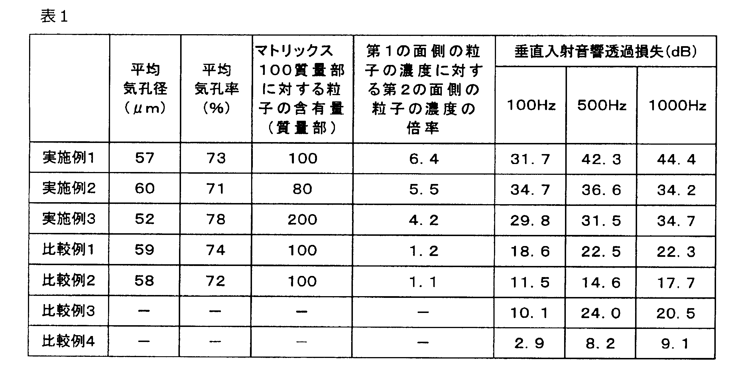
実施例1~3の多孔質体は、連続気孔を有し、第1の面側の粒子の濃度に対する第2の面側の粒子の濃度の倍率が3倍以上であるため、遮音性に優れていた。図8に示すように、実施例1の多孔質体は、質量則(面密度:3kg/m2)に則らず、広い周波数領域で遮音性に優れていた。
比較例1、2の多孔質体は、第1の面側の粒子の濃度に対する第2の面側の粒子の濃度の倍率が3倍未満であるため、遮音性が実施例1、2に比べ劣っていた。
図8の比較例3に示すように、市販の吸音材は、実施例1の多孔質体と同じ面密度にした場合、厚さは5倍となり、しかも遮音性が低周波数の領域で実施例1に比べやや劣った。
図8の比較例4に示すように、市販の吸音材は、実施例1の多孔質体と同じ厚さにした場合、遮音性が実施例1に比べかなり劣っていた。
比較例1、2の多孔質体は、第1の面側の粒子の濃度に対する第2の面側の粒子の濃度の倍率が3倍未満であるため、遮音性が実施例1、2に比べ劣っていた。
図8の比較例3に示すように、市販の吸音材は、実施例1の多孔質体と同じ面密度にした場合、厚さは5倍となり、しかも遮音性が低周波数の領域で実施例1に比べやや劣った。
図8の比較例4に示すように、市販の吸音材は、実施例1の多孔質体と同じ厚さにした場合、遮音性が実施例1に比べかなり劣っていた。
本発明を特定の態様を参照して詳細に説明したが、本発明の精神と範囲を離れることなく様々な変更および修正が可能であることは、当業者にとって明らかである。なお、本出願は、2016年8月12日付けで出願された日本特許出願(特願2016-158875)に基づいており、その全体が引用により援用される。また、ここに引用されるすべての参照は全体として取り込まれる。
本発明の多孔質体は、質量則に則らない、軽量、薄厚な遮音材としてとして有用である。
10 多孔質体
12 連続気孔
14 粒子
16 骨格
A 第1の面
B 第2の面
12 連続気孔
14 粒子
16 骨格
A 第1の面
B 第2の面
Claims (12)
- 連続気孔を有する多孔質体であり、
前記多孔質体は、第1の面と、前記第1の面とは反対側の第2の面とを有し、
前記多孔質体は、複数の粒子を含み、
前記第2の面側の前記粒子の濃度が、前記第1の面側の前記粒子の濃度の3倍以上である、多孔質体。 - 前記多孔質体が、キセロゲルを含む、請求項1に記載の多孔質体。
- 前記多孔質体の骨格を形成するマトリックスが、有機マトリックスである、請求項1または2に記載の多孔質体。
- 前記有機マトリックスが、硬化性樹脂の硬化物である、請求項3に記載の多孔質体。
- 前記連続気孔の平均気孔径が、10~150μmである、請求項1~4のいずれか一項に記載の多孔質体。
- 前記多孔質体の平均気孔率が、50~98%である、請求項1~5のいずれか一項に記載の多孔質体。
- 前記多孔質体の全体における前記粒子の含有量が、前記多孔質体の骨格を形成するマトリックス100質量部に対して、10~300質量部である、請求項1~6のいずれか一項に記載の多孔質体。
- 前記粒子の少なくとも一部が、前記連続気孔内に存在する、請求項1~7のいずれか一項に記載の多孔質体。
- 前記第1の面側から垂直に入射する音において、ASTM E2611-09に準拠した100Hzの垂直入射音響透過損失が25dB以上である、請求項1~8のいずれか一項に記載の多孔質体。
- 前記第1の面側から垂直に入射する音において、ASTM E2611-09に準拠した500Hzの垂直入射音響透過損失が30dB以上である、請求項1~9のいずれか一項に記載の多孔質体。
- 前記第1の面側から垂直に入射する音において、ASTM E2611-09に準拠した1000Hzの垂直入射音響透過損失が30dB以上である、請求項1~10のいずれか一項に記載の多孔質体。
- 請求項1~11のいずれか一項に記載の多孔質体を備えた、遮音材。
Applications Claiming Priority (2)
| Application Number | Priority Date | Filing Date | Title |
|---|---|---|---|
| JP2016-158875 | 2016-08-12 | ||
| JP2016158875A JP2019167388A (ja) | 2016-08-12 | 2016-08-12 | 多孔質体および遮音材 |
Publications (1)
| Publication Number | Publication Date |
|---|---|
| WO2018030441A1 true WO2018030441A1 (ja) | 2018-02-15 |
Family
ID=61163389
Family Applications (1)
| Application Number | Title | Priority Date | Filing Date |
|---|---|---|---|
| PCT/JP2017/028850 Ceased WO2018030441A1 (ja) | 2016-08-12 | 2017-08-08 | 多孔質体および遮音材 |
Country Status (2)
| Country | Link |
|---|---|
| JP (1) | JP2019167388A (ja) |
| WO (1) | WO2018030441A1 (ja) |
Cited By (2)
| Publication number | Priority date | Publication date | Assignee | Title |
|---|---|---|---|---|
| JP2019151509A (ja) * | 2018-03-01 | 2019-09-12 | 国立大学法人 名古屋工業大学 | 不燃断熱用無焼成固化多孔体及びその製造方法 |
| WO2023171183A1 (ja) * | 2022-03-08 | 2023-09-14 | Agc株式会社 | 防音材、防音構造および防音材の製造方法 |
Families Citing this family (2)
| Publication number | Priority date | Publication date | Assignee | Title |
|---|---|---|---|---|
| JP7383517B2 (ja) * | 2020-02-20 | 2023-11-20 | バンドー化学株式会社 | ポリウレタン構造体、防音材、ポリウレタン構造体の製造方法及びポリウレタン膜形成用液状組成物 |
| JP7705002B2 (ja) * | 2022-02-08 | 2025-07-09 | 北越コーポレーション株式会社 | セルロース多孔質体の製造方法 |
Citations (6)
| Publication number | Priority date | Publication date | Assignee | Title |
|---|---|---|---|---|
| JPS5793431U (ja) * | 1980-11-29 | 1982-06-09 | ||
| JPH07219554A (ja) * | 1994-02-08 | 1995-08-18 | Kawai Musical Instr Mfg Co Ltd | 防音材 |
| JPH08512349A (ja) * | 1993-07-07 | 1996-12-24 | ザ ダウ ケミカル カンパニー | 微孔質イソシアネートベースポリマー組成物及びその製造方法 |
| JPH10121598A (ja) * | 1996-10-16 | 1998-05-12 | Matsushita Electric Works Ltd | 吸音材およびその製造方法 |
| JP2008231194A (ja) * | 2007-03-19 | 2008-10-02 | Futamura Chemical Co Ltd | 吸油性連通多孔質構造体 |
| JP2013014717A (ja) * | 2011-07-06 | 2013-01-24 | Nitto Denko Corp | 無機粒子含有発泡体 |
-
2016
- 2016-08-12 JP JP2016158875A patent/JP2019167388A/ja active Pending
-
2017
- 2017-08-08 WO PCT/JP2017/028850 patent/WO2018030441A1/ja not_active Ceased
Patent Citations (6)
| Publication number | Priority date | Publication date | Assignee | Title |
|---|---|---|---|---|
| JPS5793431U (ja) * | 1980-11-29 | 1982-06-09 | ||
| JPH08512349A (ja) * | 1993-07-07 | 1996-12-24 | ザ ダウ ケミカル カンパニー | 微孔質イソシアネートベースポリマー組成物及びその製造方法 |
| JPH07219554A (ja) * | 1994-02-08 | 1995-08-18 | Kawai Musical Instr Mfg Co Ltd | 防音材 |
| JPH10121598A (ja) * | 1996-10-16 | 1998-05-12 | Matsushita Electric Works Ltd | 吸音材およびその製造方法 |
| JP2008231194A (ja) * | 2007-03-19 | 2008-10-02 | Futamura Chemical Co Ltd | 吸油性連通多孔質構造体 |
| JP2013014717A (ja) * | 2011-07-06 | 2013-01-24 | Nitto Denko Corp | 無機粒子含有発泡体 |
Cited By (3)
| Publication number | Priority date | Publication date | Assignee | Title |
|---|---|---|---|---|
| JP2019151509A (ja) * | 2018-03-01 | 2019-09-12 | 国立大学法人 名古屋工業大学 | 不燃断熱用無焼成固化多孔体及びその製造方法 |
| JP7057615B2 (ja) | 2018-03-01 | 2022-04-20 | 国立大学法人 名古屋工業大学 | 不燃断熱用無焼成固化多孔体及びその製造方法 |
| WO2023171183A1 (ja) * | 2022-03-08 | 2023-09-14 | Agc株式会社 | 防音材、防音構造および防音材の製造方法 |
Also Published As
| Publication number | Publication date |
|---|---|
| JP2019167388A (ja) | 2019-10-03 |
Similar Documents
| Publication | Publication Date | Title |
|---|---|---|
| Lu et al. | Fabrication of mesoporous lignocellulose aerogels from wood via cyclic liquid nitrogen freezing–thawing in ionic liquid solution | |
| Mi et al. | Flexible and transparent cellulose aerogels with uniform nanoporous structure by a controlled regeneration process | |
| Rashid et al. | Silica aerogel: Synthesis, characterization, applications, and recent advancements | |
| Salimian et al. | A review on aerogel: 3D nanoporous structured fillers in polymer‐based nanocomposites | |
| Kaya | Super absorbent, light, and highly flame retardant cellulose‐based aerogel crosslinked with citric acid | |
| Cervin et al. | Strong, water-durable, and wet-resilient cellulose nanofibril-stabilized foams from oven drying | |
| Sehaqui et al. | High-porosity aerogels of high specific surface area prepared from nanofibrillated cellulose (NFC) | |
| Moradi et al. | Organoclay nanoparticles interaction in PU: PMMA IPN foams: Relationship between the cellular structure and damping-acoustical properties | |
| Panda et al. | Superhydrophobic hybrid silica-cellulose aerogel for enhanced thermal, acoustic, and oil absorption characteristics | |
| Plappert et al. | Conformal ultrathin coating by scCO2-mediated PMMA deposition: a facile approach to add moisture resistance to lightweight ordered nanocellulose aerogels | |
| Rong et al. | Directional, super‐hydrophobic cellulose nanofiber/polyvinyl alcohol/montmorillonite aerogels as green absorbents for oil/water separation | |
| Yu et al. | General and straightforward synthetic route to phenolic resin gels templated by chitosan networks | |
| JP2019167388A (ja) | 多孔質体および遮音材 | |
| Palantöken et al. | A novel nonchemical approach to the expansion of halloysite nanotubes and their uses in chitosan composite hydrogels for broad‐spectrum dye adsorption capacity | |
| Le et al. | Toward the development of graphene/chitosan biocomposite aerogels with enhanced mechanical and thermal insulation performance | |
| JP2009185248A (ja) | 固体成分として再生セルロース及び合成高分子を有する複合材料及びその製造方法 | |
| He et al. | Nanocomposite structure based on silylated MCM-48 and poly (vinyl acetate) | |
| Zhao et al. | Luminescent and transparent nanopaper based on rare-earth up-converting nanoparticle grafted nanofibrillated cellulose derived from garlic skin | |
| Kim et al. | Facile preparation of cellulose-SiO2 composite aerogels with high SiO2 contents using a LiBr aqueous solution | |
| CN1285655C (zh) | 基于烃类聚合物或共聚物的气凝胶及其制备方法 | |
| CN107236139A (zh) | 一种高性能碳纳米管/氧化石墨烯气凝胶/聚苯乙烯复合材料及其制备方法 | |
| JP2022148855A (ja) | 異方性を有する高濃度ゲル又は多孔性材料の製造方法 | |
| CN110467421A (zh) | 一种功能性纤维素气凝胶复合材料及其制备方法 | |
| Suresh et al. | Gradient pore-structured polymeric fibrous aerogels for effective low-frequency noise absorption | |
| WO2018030442A1 (ja) | 多孔質体および遮音材 |
Legal Events
| Date | Code | Title | Description |
|---|---|---|---|
| 121 | Ep: the epo has been informed by wipo that ep was designated in this application |
Ref document number: 17839509 Country of ref document: EP Kind code of ref document: A1 |
|
| NENP | Non-entry into the national phase |
Ref country code: DE |
|
| NENP | Non-entry into the national phase |
Ref country code: JP |
|
| 122 | Ep: pct application non-entry in european phase |
Ref document number: 17839509 Country of ref document: EP Kind code of ref document: A1 |