WO2018030233A1 - ワイヤーハーネス - Google Patents
ワイヤーハーネス Download PDFInfo
- Publication number
- WO2018030233A1 WO2018030233A1 PCT/JP2017/028026 JP2017028026W WO2018030233A1 WO 2018030233 A1 WO2018030233 A1 WO 2018030233A1 JP 2017028026 W JP2017028026 W JP 2017028026W WO 2018030233 A1 WO2018030233 A1 WO 2018030233A1
- Authority
- WO
- WIPO (PCT)
- Prior art keywords
- wiring member
- wiring
- sheet
- wire harness
- parallel
- Prior art date
- Legal status (The legal status is an assumption and is not a legal conclusion. Google has not performed a legal analysis and makes no representation as to the accuracy of the status listed.)
- Ceased
Links
Images



Classifications
-
- H—ELECTRICITY
- H01—ELECTRIC ELEMENTS
- H01B—CABLES; CONDUCTORS; INSULATORS; SELECTION OF MATERIALS FOR THEIR CONDUCTIVE, INSULATING OR DIELECTRIC PROPERTIES
- H01B7/00—Insulated conductors or cables characterised by their form
-
- H—ELECTRICITY
- H01—ELECTRIC ELEMENTS
- H01B—CABLES; CONDUCTORS; INSULATORS; SELECTION OF MATERIALS FOR THEIR CONDUCTIVE, INSULATING OR DIELECTRIC PROPERTIES
- H01B7/00—Insulated conductors or cables characterised by their form
- H01B7/40—Insulated conductors or cables characterised by their form with arrangements for facilitating mounting or securing
-
- H—ELECTRICITY
- H02—GENERATION; CONVERSION OR DISTRIBUTION OF ELECTRIC POWER
- H02G—INSTALLATION OF ELECTRIC CABLES OR LINES, OR OF COMBINED OPTICAL AND ELECTRIC CABLES OR LINES
- H02G3/00—Installations of electric cables or lines or protective tubing therefor in or on buildings, equivalent structures or vehicles
- H02G3/02—Details
- H02G3/04—Protective tubing or conduits, e.g. cable ladders or cable troughs
Definitions
- This invention relates to a technique for arranging a first wiring member and a second wiring member apart from each other.
- Patent document 1 has a plurality of electric wires of a low voltage system circuit and a plurality of electric wires of a high voltage system circuit, and the plurality of electric wires of the low voltage system circuit and the plurality of electric wires of the high voltage system circuit are the same.
- a wire harness routed along a path, which separates a plurality of electric wires of the low voltage system circuit and a plurality of electric wires of the high voltage system circuit, and a plurality of electric wires and a high voltage system of the low voltage system circuit The wire harness which coat
- the plurality of electric wires of the low voltage system circuit and the plurality of electric wires of the high voltage system circuit are separated from each other, and an insulating sheet is interposed therebetween, so that a relatively large creepage distance is provided. Be placed.
- an object of the present invention is to enable the first wiring member and the second wiring member to be disposed with a space therebetween.
- a wire harness includes a first wiring member, a second wiring member arranged in parallel with the first wiring member, the first wiring member, and the A third wiring member disposed between the second wiring member, the first wiring member, the second wiring member, and the third wiring member are covered from one side of a parallel body of the third wiring member.
- the first wiring member passes between the first wiring member and the third wiring member and between the second wiring member and the third wiring member from the other surface side of the parallel body.
- a sheet-like arrangement maintaining member that covers the second wiring member.
- a 2nd aspect is a wire harness which concerns on a 1st aspect, Comprising:
- the said 1st wiring member is a wiring member used as a noise source, and the said 2nd wiring member is a wiring member which receives the influence of a noise. ing.
- a third aspect is a wire harness according to the first or second aspect, wherein the sheet-like arrangement maintaining member includes a laterally extending cover portion that covers an outer periphery of the parallel body.
- the fourth aspect is a wire harness according to any one of the first to third aspects, and further includes a cover that covers an outer periphery of the parallel body.
- the sheet-like arrangement maintaining member covers the third wiring member from one side of the parallel body of the first wiring member, the second wiring member, and the third wiring member, and the first wiring member and the first wiring member
- the first wiring member and the second wiring member are covered from the other surface side of the parallel body through the three wiring members and between the second wiring member and the third wiring member.
- the third wiring member it becomes difficult for the third wiring member to be detached from the first wiring member and the second wiring member to the one surface side of the parallel body.
- the parallel state of the first wiring member, the second wiring member, and the third wiring member is easily maintained.
- the 3rd wiring member intervenes between the 1st wiring member and the 2nd wiring member, the 1st wiring member and the 2nd wiring member can be arranged at intervals for the 3rd wiring member.
- the influence of noise from the first wiring member to the second wiring member can be reduced.
- the outer periphery of the parallel body can be covered and protected by the laterally extending cover.
- the outer periphery of the parallel body can be covered and protected by the covering portion.
- FIG. 2 is a schematic sectional view taken along line II-II in FIG. 1. It is explanatory drawing which shows the example of a manufacturing method of a wire harness. It is explanatory drawing which shows the example of a manufacturing method of a wire harness. It is explanatory drawing which shows the example of a manufacturing method of a wire harness. It is a schematic sectional drawing which shows the wire harness which concerns on a modification.
- FIG. 1 is a schematic plan view showing the wire harness 10
- FIG. 2 is a schematic cross-sectional view taken along the line II-II of FIG.
- the wire harness 10 includes a first wiring member 20, a second wiring member 30, a third wiring member 40, and a sheet-like arrangement maintaining member 50.
- a third wiring member 40 is provided between the first wiring member 20 and the second wiring member 30, and the first wiring member 20 and the second wiring member 30 are arranged in parallel with a space therebetween. ing. Thereby, the influence of the noise between the 1st wiring member 20 and the 2nd wiring member 30 can be reduced.
- the 1st wiring member 20, the 2nd wiring member 30, and the 3rd wiring member 40 may branch. End portions of the first wiring member 20, the second wiring member 30, and the third wiring member 40 are connected to various electrical components mounted on a vehicle or the like via a connector or the like. That is, the wire harness 10 is used as wiring for electrically connecting various electrical components and the like in the vehicle.
- the first wiring member 20 is a wiring member connected to an electrical component or the like in a vehicle or the like.
- the first wiring member 20 is a wiring member including at least one electric wire 21.
- the first wiring member 20 will be described as an example in which a plurality of electric wires 21 are bundled.
- the second wiring member 30 is a wiring member connected to an electrical component or the like in a vehicle or the like, and here is a wiring member including at least one electric wire 21.
- the second wiring member 30 will be described as an example of a twisted electric wire 24 in which a plurality of (for example, two) electric wires 21 are twisted and a sheath 22 is formed on the outer periphery thereof. At least a part of the second wiring member 30 is disposed in parallel to the first wiring member 20.
- the third wiring member 40 is a wiring member connected to an electrical component or the like in a vehicle or the like.
- the third wiring member 40 is a wiring member including at least one electric wire 21.
- the third wiring member 40 will be described as an example in which a plurality of electric wires 21 are bundled.
- the third wiring member 40 is thinner than the first wiring member 20 and thicker than the second wiring member 30. But the thickness of a 1st wiring member, a 2nd wiring member, and a 3rd wiring member is not restricted to the said example.
- the third wiring member may be thicker than the first and second wiring members.
- the third wiring member 40 is disposed between the first wiring member 20 and the second wiring member 30.
- the 1st wiring member 20, the 2nd wiring member 30, and the 3rd wiring member 40 contain the part arrange
- a portion where the first wiring member 20, the second wiring member 30 and the third wiring member 40 are arranged in parallel is referred to as a parallel body 18.
- the relationship between the first wiring member 20 and the second wiring member 30 will be described.
- the first wiring member 20 is a member that easily becomes a noise source, and the second wiring member 30 is affected by the noise from the first wiring member 20. It is conceivable that the member is easily received.
- Examples of the combination of the wiring members 20 and 30 include an example in which the first wiring member 20 includes a power supply line and a signal line of the second wiring member 30. Further, there is an example in which the first wiring member 20 includes a high-voltage power supply line and the second wiring member 30 includes a lower-voltage power supply line.
- the relationship between the first wiring member 20, the second wiring member 30, and the third wiring member 40 will be described.
- the third wiring member 40 noise applied to the second wiring member 30 rather than the first wiring member 20 is described.
- the influence is small and the influence of noise received from the first wiring member 20 is smaller than that of the second wiring member 30.
- the first wiring member 20 is a high-voltage power supply line
- the second wiring member 30 is a signal.
- a combination in which the third wiring member 40 is a low-voltage power supply line is conceivable.
- the first wiring member 20 is a power supply line
- the second wiring member 30 is a signal line that is susceptible to noise such as a signal line for high-speed communication
- the third wiring member 40 is a signal for a sensor.
- a combination that is a signal line that is not easily affected by noise, such as a line or a signal line for low-speed communication, can be considered.
- the first wiring member 20 includes a power supply line
- the second wiring member 30 is a cable for in-vehicle LAN communication
- the second wiring member 30 is a high-speed that conforms to the Ethernet (registered trademark) standard.
- the third wiring member 40 is a communication cable
- the third wiring member 40 includes a signal line that is not easily affected by noise, such as a sensor signal line or a low-speed communication signal line.
- the sheet-like arrangement maintaining member 50 covers the third wiring member 40 from one side (the upper side in FIG. 2) of the parallel body 18, and between the first wiring member 20 and the third wiring member 40, and the first The first wiring member 20 and the third wiring member 40 are covered from the other surface side (lower side in FIG. 2) of the parallel body 18 through the space between the two wiring members 30 and the third wiring member 40.
- the third wiring member 40 is prevented from moving above the parallel body 18 and the first wiring member 20 and the second wiring member 30 are restrained from moving below the parallel body 18, thereby having
- the 1st wiring member 20, the 2nd wiring member 30, and the 3rd wiring member 40 play the role which keeps a parallel state.
- the sheet-like arrangement maintaining member 50 is formed in an elongated sheet shape.
- the sheet-like arrangement maintaining member 50 is formed of a sheet-like member that can be bent without breaking.
- Examples of the sheet-like arrangement maintaining member 50 include a resin sheet material (resin) in which the inside is uniformly filled with a resin, such as a PP (polypropylene) sheet, a PVC (polyvinyl chloride) sheet, or a PET (polyethylene terephthalate) sheet. Including thin films such as films), hollow plate materials such as plastic corrugated cardboard, foam sheets, nonwoven fabrics, and the like can be used.
- the sheet-like arrangement maintaining member 50 is bent so as to draw a gentle curve, but may be bent via a fold.
- the sheet-like arrangement maintaining member 50 one provided with conductivity by metal vapor deposition, metal plating, or the like may be used.
- the sheet-like arrangement maintaining member 50 includes a sheet main body portion 52 and a side extension cover portion 56.
- the sheet main body 52 is formed in a rectangular shape.
- the length of the sheet body 52 is the same as the length of the portion of the first wiring member 20, the second wiring member 30, and the third wiring member 40 that is maintained in a parallel state by the sheet-like arrangement maintaining member 50. Is set to The width dimension of the sheet main body 52 is set to be longer than a length that covers about half of each of the first wiring member 20, the second wiring member 30, and the third wiring member 40.
- the intermediate portion in the width direction of the sheet main body 52 covers the third wiring member 40 from the one surface side (the upper side in FIG. 2) of the parallel body 18 about a half circumference.
- the both sides of the portion of the sheet main body 52 that covers the third wiring member 40 are between the first wiring member 20 and the third wiring member 40 and between the second wiring member 30 and the third wiring member 40. Is passed from one side of the parallel body 18 to the other side (from top to bottom in FIG. 2).
- both side portions of the sheet main body 52 cover the first wiring member 20 and the second wiring member 30 from the other surface side (lower side in FIG. 2) of the parallel body 18 to the extent of about a half turn or more than a half turn.
- the side extension cover part 56 is formed in a rectangular shape extending outward from one side part of the sheet main body part 52.
- the length dimension of the side extension cover portion 56 is set to be the same as the length dimension of the seat body portion 52.
- the length dimension of a side extension cover part may be larger than the length dimension of the sheet
- the side extension cover part may be provided only in a part of one side part of the seat body part.
- the width dimension of the side extension cover portion 56 is set to a size that covers the outer peripheral portion of the parallel body 18 one or more times.
- the side extension cover portion 56 extends from one side portion of the sheet main body portion 52 and is bent so as to cover the entire outer periphery of the parallel body 18.
- the end portion of the side extension cover portion 56 is joined to the outer periphery of the wound portion of the side extension cover portion 56 by a joining portion 57 such as a double-sided tape.
- the edge part of the side extension cover part 56 may be joined to the outer periphery of the wound part of the side extension cover part 56 by an adhesive agent, heat welding, or the like.
- the state which the side extension cover part 56 covers the parallel body 18 may be maintained by winding binding members, such as an adhesive tape and a binding band, on the outer periphery of the side extension cover part 56.
- 3 to 5 are explanatory views showing an example of a method for manufacturing the wire harness 10.
- the third wiring member 40 is placed on the work table 60 incorporated in the wire harness assembly drawing board or the like.
- the work sheet 60 is covered with the sheet main body 52 of the sheet-like arrangement maintaining member 50 from the upper side of the third wiring member 40.
- the intermediate portion in the width direction of the sheet main body 52 covers the second wiring member 30 from above, and both side portions of the sheet main body 52 and the side extension covering portions 56 are on the work table 60 on both sides of the third wiring member 40. It will be in the state arranged above.
- the first wiring member 20 and the second wiring member 30 are placed on both sides of the third wiring member 40 and on both sides in the width direction of the sheet main body 52. Thereafter, both side portions of the sheet main body 52 are covered around the first wiring member 20 and the second wiring member 30, and further, the first wiring member 20, the second wiring member 30, and the second wiring member 56 are covered by the side extension cover portion 56. 3
- the wiring member 40 is covered. And the edge part of the side extension cover part 56 is joined to the wound part of the side extension cover part 56 with a double-sided tape etc. Alternatively, a binding member such as an adhesive tape is wound around the side extension cover portion 56 to maintain the binding state.
- the wire harness 10 can be easily manufactured.
- the sheet main body portion 52 of the sheet-like arrangement maintaining member 50 covers the third wiring member 40 from one side of the parallel body 18, and the first wiring member 20 and the first wiring member 20.
- the first wiring member 20 and the second wiring member 30 are covered from the other surface side of the parallel body 18 through the third wiring member 40 and between the second wiring member 30 and the third wiring member 40. .
- the parallel state of the 1st wiring member 20, the 2nd wiring member 30, and the 3rd wiring member 40 becomes easy to be maintained.
- the third wiring member 40 is interposed between the first wiring member 20 and the second wiring member 30, the first wiring member 20 and the second wiring member 30 are separated by the diameter dimension of the third wiring member 40. It is possible to arrange them at intervals. Thereby, the influence of the noise between the 1st wiring member 20 and the 2nd wiring member 30, especially the influence of the noise from the 1st wiring member 20 to the 2nd wiring member 30 can be reduced.
- shielded wire having a metal braid or the like formed on the outer periphery.
- the use of such a shielded wire is expensive.
- the influence of noise is suppressed by providing a spatial distance between the first wiring member 20 and the second wiring member 30.
- shielded wires may be adopted as the wires constituting the first wiring member 20 and the second wiring member 30, or a shield layer may be provided between them.
- the outer periphery of the parallel body 18 can be covered and protected by the side extension cover portion 56.
- the side extension cover portion 56 covers the outer periphery of the parallel body 18 in which the third wiring member 40 is disposed between the first wiring member 20 and the second wiring member 30. It is possible to prevent the parallel body 18 from being removed to the other surface side, and thus to maintain the parallel configuration of the first wiring member 20, the second wiring member 30, and the third wiring member 40 more reliably.
- FIG. 6 is a schematic cross-sectional view showing a wire harness 110 according to a modification.
- the following sheet-like arrangement maintaining member 150 is used instead of the sheet-like arrangement maintaining member 50.
- the sheet-like arrangement maintaining member 150 is configured such that, in the sheet-like arrangement maintaining member 50, the side extension cover portion 56 is omitted and only a portion corresponding to the sheet main body portion 52 is provided.
- the sheet-like arrangement maintaining member 150 covers the first wiring member 20, the second wiring member 30, and the third wiring member 40 in the same manner as the sheet main body portion 52, thereby the first wiring member. 20, the 2nd wiring member 30 and the 3rd wiring member 40 are maintained in the parallel form.
- the wire harness 110 includes a cover portion 156 separately from the sheet-like arrangement maintaining member 150.
- the cover portion 156 covers the outer periphery of the parallel body 18 of the first wiring member 20, the second wiring member 30, and the third wiring member 40.
- the end portion on the winding end side of the cover portion 156 is joined to the outer periphery of the winding start side portion of the cover portion 156 by a double-sided tape or the like.
- the parallel body 18 is protected by the cover part 156.
- the form of the parallel body 18 is more reliably maintained.
- a binding member such as an adhesive tape or a binding band may be wound around the outer periphery of the parallel body 18.
- a plurality of sheet-like arrangement maintaining members 50 and 150 covering the parallel body 18 may be provided by alternately changing the direction of covering the parallel body 18.
Landscapes
- Engineering & Computer Science (AREA)
- Architecture (AREA)
- Civil Engineering (AREA)
- Structural Engineering (AREA)
- Details Of Indoor Wiring (AREA)
- Insulated Conductors (AREA)
Abstract
第1配線部材と第2配線部材とを、間隔をあけて配設できるようにすることを目的とする。ワイヤーハーネスは、第1配線部材と、第1配線部材に対して並列して配置された第2配線部材と、第1配線部材と第2配線部材との間に配設された第3配線部材と、第1配線部材と第2配線部材と第3配線部材の並列体の一方面側から第3配線部材を覆うと共に、第1配線部材と第3配線部材との間、及び、第2配線部材と第3配線部材との間を通って、並列体の他方面側から第1配線部材と第2配線部材とを覆うシート状配列維持部材とを備える。
Description
この発明は、第1配線部材と第2配線部材とを離して配設する技術に関する。
特許文献1は、低電圧系回路の複数の電線と、高電圧系回路の複数の電線とを有し、これら低電圧系回路の複数の電線と高電圧系回路の複数の電線とを同一の経路に沿って配索するワイヤーハーネスであって、前記低電圧系回路の複数の電線と前記高電圧系回路の複数の電線とを分けると共に、これら低電圧系回路の複数の電線と高電圧系回路の複数の電線との全外周を別々に包み込むよう折り曲げた絶縁シートによって外装を施したワイヤーハーネスを開示している。このワイヤーハーネスでは、低電圧系回路の複数の電線と高電圧系回路の複数の電線とは互いに分離され、且つ、双方の間に絶縁シートが介在されることから比較的大きい沿面距離を持って配置される。
ところで、電線間において、電磁ノイズの影響を避けるためには、電線間の空間距離を設けることが好ましい。特許文献1に開示の技術では、低電圧系回路の複数の電線と、高電圧系回路の複数の電線との間には、絶縁シートの厚み分の空間距離を確保できることができるだけであるので、ノイズ対策として不十分となる恐れがある。
そこで、本発明は、第1配線部材と第2配線部材とを、間隔をあけて配設できるようにすることを目的とする。
上記課題を解決するため、第1の態様に係るワイヤーハーネスは、第1配線部材と、前記第1配線部材に対して並列して配置された第2配線部材と、前記第1配線部材と前記第2配線部材との間に配設された第3配線部材と、前記第1配線部材と前記第2配線部材と前記第3配線部材の並列体の一方面側から前記第3配線部材を覆うと共に、前記第1配線部材と前記第3配線部材との間、及び、前記第2配線部材と前記第3配線部材との間を通って、前記並列体の他方面側から前記第1配線部材と前記第2配線部材とを覆うシート状配列維持部材とを備える。
第2の態様は、第1の態様に係るワイヤーハーネスであって、前記第1配線部材は、ノイズ源となる配線部材であり、前記第2配線部材は、ノイズの影響を受ける配線部材とされている。
第3の態様は、第1又は第2の態様に係るワイヤーハーネスであって、前記シート状配列維持部材は、前記並列体の外周囲を覆う側方延長覆い部を含む。
第4の態様は、第1から第3のいずれか1つの態様に係るワイヤーハーネスであって、前記並列体の外周囲を覆う覆い部をさらに備える。
第1の態様によると、シート状配列維持部材が、第1配線部材と第2配線部材と第3配線部材の並列体の一方面側から第3配線部材を覆うと共に、第1配線部材と第3配線部材との間、及び、第2配線部材と第3配線部材との間を通って、並列体の他方面側から第1配線部材と第2配線部材とを覆う。このため、第3配線部材が、第1配線部材と第2配線部材との間から並列体の一方面側に脱し難くなる。これにより、第1配線部材と第2配線部材と第3配線部材との並列状態が維持され易くなる。そして、第1配線部材と第2配線部材との間に第3配線部材が介在するため、第1配線部材と第2配線部材とを、第3配線部材分の間隔をあけて配設できる。
第2の態様によると、第1配線部材から第2配線部材へのノイズの影響を少なくできる。
第3の態様によると、側方延長覆い部によって並列体の外周囲を覆って保護することができる。
第4の態様によると、覆い部によって並列体の外周囲を覆って保護することができる。
以下、実施形態に係るワイヤーハーネスについて説明する。図1はワイヤーハーネス10を示す概略平面図であり、図2は図1のII-II線概略断面図である。
ワイヤーハーネス10は、第1配線部材20と、第2配線部材30と、第3配線部材40と、シート状配列維持部材50とを備える。第1配線部材20と第2配線部材30との間には第3配線部材40が設けられており、第1配線部材20と第2配線部材30とが間隔をあけて並列状態に配設されている。これにより、第1配線部材20と第2配線部材30間のノイズの影響を低減可能となっている。なお、ワイヤーハーネス10の端部等において、第1配線部材20と第2配線部材30と第3配線部材40とが分岐していてもよい。第1配線部材20、第2配線部材30及び第3配線部材40の端部は、コネクタ等を介して車両等に搭載された各種電気部品等に接続される。つまり、ワイヤーハーネス10は、車両において各種電気部品等を電気的に接続する配線として用いられる。
第1配線部材20は、車両等において、電気部品等に接続される配線用の部材であり、ここでは、少なくとも1本の電線21を含む配線部材である。本実施形態においては、第1配線部材20は、複数の電線21が束ねられた構成である例で説明する。
第2配線部材30は、車両等において、電気部品等に接続される配線用の部材であり、ここでは、少なくとも1本の電線21を含む配線部材である。本実施形態においては、第2配線部材30は、複数(例えば、2本)の電線21が撚り合わされると共にその外周にシース22が形成されたツイスト電線24である例で説明する。本第2配線部材30の少なくとも一部は、上記第1配線部材20に対して並列して配設される。
第3配線部材40は、車両等において、電気部品等に接続される配線用の部材であり、ここでは、少なくとも1本の電線21を含む配線部材である。本実施形態においては、第3配線部材40は、複数の電線21が束ねられた構成である例で説明する。なお、図2では、第3配線部材40は、第1配線部材20よりも細く、第2配線部材30よりも太い。もっとも、第1配線部材、第2配線部材、第3配線部材の太さは上記例に限られない。例えば、第3配線部材が第1及び第2配線部材よりも太くてもよい。
この第3配線部材40の少なくとも一部は、第1配線部材20と第2配線部材30との間に配設されている。このため、第1配線部材20、第2配線部材30及び第3配線部材40は、同一平面上において並列するように配設された部分を含む。第1配線部材20、第2配線部材30及び第3配線部材40が並列配置された部分を、並列体18ということとする。
上記第1配線部材20と第2配線部材30との関係で説明すると、第1配線部材20はノイズ源となりやすい部材であり、第2配線部材30は第1配線部材20からのノイズの影響を受けやすい部材であることが考えられる。このような配線部材20、30の組み合わせとしては、例えば、第1配線部材20が電源線を含み、第2配線部材30の信号線を含むものである例が挙げられる。また、第1配線部材20が高電圧系の電源線を含み、第2配線部材30がそれよりも低電圧系の電源線を含むものである例が挙げられる。
さらに、第1配線部材20、第2配線部材30及び第3配線部材40との関係で説明すると、第3配線部材40としては、第1配線部材20よりも第2配線部材30に与えるノイズの影響が小さいものであって、第2配線部材30よりも第1配線部材20から受けるノイズの影響が小さいものである例が挙げられる。このような、第1配線部材20、第2配線部材30、第3配線部材40の組み合わせとしては、例えば、第1配線部材20が高電圧系の電源線であり、第2配線部材30が信号線であり、第3配線部材40が低電圧系の電源線である組み合わせが考えられる。また、例えば、第1配線部材20が電源線であり、第2配線部材30が高速通信用の信号線などのノイズの影響を受けやすい信号線であり、第3配線部材40がセンサ用の信号線又は低速通信用の信号線などのノイズの影響を受けにくい信号線である組み合わせが考えられる。
ここでは、第1配線部材20が電源線を含み、第2配線部材30が、車内LAN通信用のケーブルであり、特にここでは、第2配線部材30がイーサネット(登録商標)規格に準拠する高速通信用のケーブルであり、第3配線部材40がセンサ用の信号線又は低速通信用の信号線などのノイズの影響を受けにくい信号線を含む例で説明する。
シート状配列維持部材50は、上記並列体18の一方面側(図2の上側)から第3配線部材40を覆うと共に、第1配線部材20と第3配線部材40との間、及び、第2配線部材30と第3配線部材40との間を通って、並列体18の他方面側(図2の下側)から第1配線部材20と第3配線部材40とを覆う。これにより、第3配線部材40が並列体18の上方に移動することを抑制すると共に、第1配線部材20及び第2配線部材30が並列体18の下方に移動することを抑制し、もって、第1配線部材20、第2配線部材30及び第3配線部材40が並列状態を保つようにする役割を果す。
より具体的には、シート状配列維持部材50は、細長いシート状に形成されている。シート状配列維持部材50は、割れることなく曲げ可能なシート状部材により形成される。かかるシート状配列維持部材50としては、例えば、PP(ポリプロピレン)シート、PVC(ポリ塩化ビニル)シート又はPET(ポリエチレンテレフタレート)シート等、内部が一様に樹脂で埋まっている樹脂製シート材(樹脂製フィルム等の薄手のものを含む)、プラスチックダンボール等の中空板材、発泡シート、不織布等を用いることができる。本実施形態では、シート状配列維持部材50は、緩やかにカーブを描くように曲げられているが、折目を介して曲げられていてもよい。また、シート状配列維持部材50として、金属蒸着、金属メッキ等によって導電性が付与されたものが用いられてもよい。
ここでは、シート状配列維持部材50は、シート本体部52と、側方延長覆い部56とを備える。
シート本体部52は、長方形状に形成されている。シート本体部52の長さ寸法は、第1配線部材20、第2配線部材30及び第3配線部材40のうち本シート状配列維持部材50によって並列状態が維持される部分の長さ寸法と同じに設定されている。シート本体部52の幅寸法は、第1配線部材20、第2配線部材30及び第3配線部材40のそれぞれを半分程度覆える程度の長さ以上に設定されている。
シート本体部52の幅方向中間部は、並列体18の一方面側(図2の上側)から第3配線部材40を半周程度覆っている。シート本体部52のうち第3配線部材40を覆う部分の両側部は、第1配線部材20と第3配線部材40との間、及び、第2配線部材30と第3配線部材40との間を、並列体18の一方面側から他方面側(図2では上から下へ)へと通っている。そして、シート本体部52の両側部が、並列体18の他方面側(図2では下側)から第1配線部材20及び第2配線部材30を半周程度又は半周を超える程度覆っている。
側方延長覆い部56は、シート本体部52の一側部から外方に延出する長方形状に形成されている。ここでは、側方延長覆い部56の長さ寸法は、シート本体部52の長さ寸法と同じに設定されている。もっとも、側方延長覆い部の長さ寸法は、シート本体部52の長さ寸法より大きくてもよいし、小さくてもよい。また、シート本体部の一側部の一部にのみ、側方延長覆い部が設けられていてもよい。側方延長覆い部56の幅寸法は、並列体18の外周部を一周以上覆える大きさに設定されている。
側方延長覆い部56は、シート本体部52の一側部から延出して、並列体18の全体の外周を覆うように曲げられている。側方延長覆い部56の端部は、両面テープ等の接合部57によって、側方延長覆い部56のうち巻付け済の部分の外周に接合されている。側方延長覆い部56の端部は、接着剤、熱溶着等によって側方延長覆い部56のうち巻付け済の部分の外周に接合されてもよい。また、側方延長覆い部56の外周に粘着テープ、結束バンド等の結束部材を巻付けることによって、側方延長覆い部56が並列体18を覆う状態が維持されてもよい。
図3から図5は、上記ワイヤーハーネス10の製造方法例を示す説明図である。
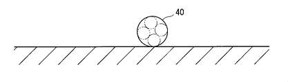
まず、図3に示すように、ワイヤーハーネス組立図板等に組込まれた作業台60上に、第3配線部材40を載置する。
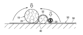
そして、図4に示すように、作業台60上で、第3配線部材40の上側からシート状配列維持部材50のシート本体部52を被せる。この状態では、シート本体部52の幅方向中間部が第2配線部材30を上側から覆い、シート本体部52の両側部及び側方延長覆い部56が第3配線部材40の両側で作業台60上に配設された状態となる。
次に図5に示すように、第3配線部材40の両側であってシート本体部52の幅方向両側部に、第1配線部材20及び第2配線部材30を載置する。この後、シート本体部52の両側部を第1配線部材20及び第2配線部材30の周囲に被せ、さらに、側方延長覆い部56によって、第1配線部材20、第2配線部材30及び第3配線部材40を覆う。そして、側方延長覆い部56の端部を両面テープ等によって側方延長覆い部56のうちの巻付け済の部分に接合する。あるいは、側方延長覆い部56の周囲に粘着テープ等の結束部材を巻付けて結束状態に維持する。
このようにして、ワイヤーハーネス10を容易に製造することができる。
以上のように構成されたワイヤーハーネス10によると、シート状配列維持部材50のシート本体部52が、並列体18の一方面側から第3配線部材40を覆うと共に、第1配線部材20と第3配線部材40との間、及び、第2配線部材30と第3配線部材40との間を通って、並列体18の他方面側から第1配線部材20と第2配線部材30とを覆う。このため、第3配線部材40が、第1配線部材20と第2配線部材30との間から並列体18の一方面側に脱し難くなる。これにより、第1配線部材20、第2配線部材30及び第3配線部材40の並列状態が維持され易くなる。また、第1配線部材20と第2配線部材30との間に第3配線部材40が介在するため、第1配線部材20と第2配線部材30とを、第3配線部材40の直径寸法分の間隔をあけて配設することができる。これにより、第1配線部材20と第2配線部材30との間でのノイズの影響、特に、第1配線部材20から第2配線部材30へのノイズの影響を低減できる。
なお、配線部材間で電磁ノイズの影響を抑制する方法としては、外周に金属製の編組等が形成されたシールド電線を用いることが想定される。しかしながら、そのようなシールド電線を用いると高コストとなる。これに対して、ワイヤーハーネス10では、第1配線部材20と第2配線部材30との間に空間的距離を設けることで、ノイズの影響を抑制している。これにより、コストアップを抑制しつつ、第1配線部材20と第2配線部材30との間のノイズの影響を低減することができる。もちろん、第1配線部材20及び第2配線部材30を構成する電線として、シールド電線が採用されたり、それらの間にシールド層が設けられたりしてもよい。
また、側方延長覆い部56によって並列体18の外周囲を覆って保護することができる。側方延長覆い部56は、第1配線部材20と第2配線部材30との間に第3配線部材40が配設された並列体18の外周囲を覆うことによって、第3配線部材40が並列体18の他方面側に脱することを抑制し、もって、第1配線部材20、第2配線部材30及び第3配線部材40の並列形態をより確実に維持する役割をも果す。
{変形例}
図6は変形例に係るワイヤーハーネス110を示す概略断面図である。このワイヤーハーネス110では、上記シート状配列維持部材50に代えて、次のシート状配列維持部材150が用いられている。シート状配列維持部材150は、上記シート状配列維持部材50において、側方延長覆い部56を省略し、シート本体部52に対応する部分のみを備えた構成とされている。そして、シート状配列維持部材150が上記シート本体部52と同様の態様にて、第1配線部材20、第2配線部材30及び第3配線部材40を覆っており、これにより、第1配線部材20、第2配線部材30及び第3配線部材40が並列形態に保たれている。
図6は変形例に係るワイヤーハーネス110を示す概略断面図である。このワイヤーハーネス110では、上記シート状配列維持部材50に代えて、次のシート状配列維持部材150が用いられている。シート状配列維持部材150は、上記シート状配列維持部材50において、側方延長覆い部56を省略し、シート本体部52に対応する部分のみを備えた構成とされている。そして、シート状配列維持部材150が上記シート本体部52と同様の態様にて、第1配線部材20、第2配線部材30及び第3配線部材40を覆っており、これにより、第1配線部材20、第2配線部材30及び第3配線部材40が並列形態に保たれている。
また、ワイヤーハーネス110は、シート状配列維持部材150とは別に覆い部156を備える。覆い部156は、第1配線部材20、第2配線部材30及び第3配線部材40の並列体18の外周囲を覆っている。覆い部156の巻き終り側の端部は、覆い部156のうち巻始め側の部分の外周に、両面テープ等によって接合されている。これにより、並列体18が覆い部156によって保護される。また、並列体18の形態がより確実に保たれるようになっている。
覆い部156を設ける代りに、並列体18の外周に粘着テープ、結束バンド等の結束部材を巻付けるようにしてもよい。
また、上記実施形態及び変形例において、並列体18を覆うシート状配列維持部材50、150が、並列体18を覆う向きを交互に変えて複数設けられてもよい。
以上のようにこの発明は詳細に説明されたが、上記した説明は、すべての局面において、例示であって、この発明がそれに限定されるものではない。例示されていない無数の変形例が、この発明の範囲から外れることなく想定され得るものと解される。
10、110 ワイヤーハーネス
18 並列体
20 第1配線部材
21 電線
24 ツイスト電線
30 第2配線部材
40 第3配線部材
50、150 シート状配列維持部材
52 シート本体部
56 側方延長覆い部
156 覆い部
18 並列体
20 第1配線部材
21 電線
24 ツイスト電線
30 第2配線部材
40 第3配線部材
50、150 シート状配列維持部材
52 シート本体部
56 側方延長覆い部
156 覆い部
Claims (4)
- 第1配線部材と、
前記第1配線部材に対して並列して配置された第2配線部材と、
前記第1配線部材と前記第2配線部材との間に配設された第3配線部材と、
前記第1配線部材と前記第2配線部材と前記第3配線部材の並列体の一方面側から前記第3配線部材を覆うと共に、前記第1配線部材と前記第3配線部材との間、及び、前記第2配線部材と前記第3配線部材との間を通って、前記並列体の他方面側から前記第1配線部材と前記第2配線部材とを覆うシート状配列維持部材と、
を備えるワイヤーハーネス。 - 請求項1に記載のワイヤーハーネスであって、
前記第1配線部材は、ノイズ源となる配線部材であり、
前記第2配線部材は、ノイズの影響を受ける配線部材である、ワイヤーハーネス。 - 請求項1又は請求項2に記載のワイヤーハーネスであって、
前記シート状配列維持部材は、前記並列体の外周囲を覆う側方延長覆い部を含む、ワイヤーハーネス。 - 請求項1から請求項3のいずれか1項に記載のワイヤーハーネスであって、
前記並列体の外周囲を覆う覆い部をさらに備える、ワイヤーハーネス。
Applications Claiming Priority (2)
| Application Number | Priority Date | Filing Date | Title |
|---|---|---|---|
| JP2016-156320 | 2016-08-09 | ||
| JP2016156320A JP2018026229A (ja) | 2016-08-09 | 2016-08-09 | ワイヤーハーネス |
Publications (1)
| Publication Number | Publication Date |
|---|---|
| WO2018030233A1 true WO2018030233A1 (ja) | 2018-02-15 |
Family
ID=61162571
Family Applications (1)
| Application Number | Title | Priority Date | Filing Date |
|---|---|---|---|
| PCT/JP2017/028026 Ceased WO2018030233A1 (ja) | 2016-08-09 | 2017-08-02 | ワイヤーハーネス |
Country Status (2)
| Country | Link |
|---|---|
| JP (1) | JP2018026229A (ja) |
| WO (1) | WO2018030233A1 (ja) |
Cited By (2)
| Publication number | Priority date | Publication date | Assignee | Title |
|---|---|---|---|---|
| CN112204836A (zh) * | 2018-05-30 | 2021-01-08 | 株式会社自动网络技术研究所 | 配线构件 |
| US11342690B2 (en) * | 2018-08-01 | 2022-05-24 | Autonetworks Technologies, Ltd. | Fixing structure of splice part |
Families Citing this family (1)
| Publication number | Priority date | Publication date | Assignee | Title |
|---|---|---|---|---|
| JP2021078167A (ja) * | 2019-11-05 | 2021-05-20 | 矢崎総業株式会社 | プロテクタおよびワイヤハーネス |
Citations (2)
| Publication number | Priority date | Publication date | Assignee | Title |
|---|---|---|---|---|
| JP2014143773A (ja) * | 2013-01-22 | 2014-08-07 | Auto Network Gijutsu Kenkyusho:Kk | ワイヤハーネス |
| JP2015082352A (ja) * | 2013-10-21 | 2015-04-27 | 住友電装株式会社 | ワイヤーハーネス |
-
2016
- 2016-08-09 JP JP2016156320A patent/JP2018026229A/ja active Pending
-
2017
- 2017-08-02 WO PCT/JP2017/028026 patent/WO2018030233A1/ja not_active Ceased
Patent Citations (2)
| Publication number | Priority date | Publication date | Assignee | Title |
|---|---|---|---|---|
| JP2014143773A (ja) * | 2013-01-22 | 2014-08-07 | Auto Network Gijutsu Kenkyusho:Kk | ワイヤハーネス |
| JP2015082352A (ja) * | 2013-10-21 | 2015-04-27 | 住友電装株式会社 | ワイヤーハーネス |
Cited By (3)
| Publication number | Priority date | Publication date | Assignee | Title |
|---|---|---|---|---|
| CN112204836A (zh) * | 2018-05-30 | 2021-01-08 | 株式会社自动网络技术研究所 | 配线构件 |
| CN112204836B (zh) * | 2018-05-30 | 2022-06-14 | 株式会社自动网络技术研究所 | 配线构件 |
| US11342690B2 (en) * | 2018-08-01 | 2022-05-24 | Autonetworks Technologies, Ltd. | Fixing structure of splice part |
Also Published As
| Publication number | Publication date |
|---|---|
| JP2018026229A (ja) | 2018-02-15 |
Similar Documents
| Publication | Publication Date | Title |
|---|---|---|
| JP6010817B2 (ja) | ワイヤハーネス同士の合体構造 | |
| KR20140015509A (ko) | 실드 전선 | |
| JP2014519176A5 (ja) | ||
| CN105448397A (zh) | 线束及线束的制造方法 | |
| WO2015005402A1 (ja) | ワイヤハーネス | |
| WO2018030233A1 (ja) | ワイヤーハーネス | |
| US20180277282A1 (en) | Shielded conductive path | |
| US9384873B2 (en) | Differential signal transmission cable | |
| JP2014207836A (ja) | プロテクタおよびワイヤハーネス | |
| WO2015005403A1 (ja) | ワイヤハーネス | |
| JP2015130276A (ja) | シールド電線 | |
| CN103282973B (zh) | 导线屏蔽结构 | |
| JP5841856B2 (ja) | ワイヤハーネス | |
| WO2018030085A1 (ja) | ワイヤーハーネス、シート状間隔維持部材及びワイヤーハーネスの製造方法 | |
| CN107210093A (zh) | 电线模块 | |
| WO2018030151A1 (ja) | ワイヤーハーネス及びワイヤーハーネスの製造方法 | |
| JP7107298B2 (ja) | 配線部材の取付構造 | |
| JP5810933B2 (ja) | ワイヤーハーネス | |
| WO2018030141A1 (ja) | ワイヤーハーネス及びワイヤーハーネスの製造方法 | |
| JP6149737B2 (ja) | 電線モジュール及びプロテクタ | |
| JP2016165166A (ja) | 保護部材付電線の配設構造及び保護部材付電線 | |
| JP2016021844A (ja) | ワイヤーハーネス外装材およびワイヤーハーネス | |
| JP2015116099A (ja) | ワイヤーハーネス | |
| WO2018030099A1 (ja) | ワイヤーハーネス | |
| JP5607133B2 (ja) | 線状物の固定構造 |
Legal Events
| Date | Code | Title | Description |
|---|---|---|---|
| 121 | Ep: the epo has been informed by wipo that ep was designated in this application |
Ref document number: 17839306 Country of ref document: EP Kind code of ref document: A1 |
|
| NENP | Non-entry into the national phase |
Ref country code: DE |
|
| 122 | Ep: pct application non-entry in european phase |
Ref document number: 17839306 Country of ref document: EP Kind code of ref document: A1 |