WO2018030131A1 - 配線モジュール - Google Patents
配線モジュール Download PDFInfo
- Publication number
- WO2018030131A1 WO2018030131A1 PCT/JP2017/026630 JP2017026630W WO2018030131A1 WO 2018030131 A1 WO2018030131 A1 WO 2018030131A1 JP 2017026630 W JP2017026630 W JP 2017026630W WO 2018030131 A1 WO2018030131 A1 WO 2018030131A1
- Authority
- WO
- WIPO (PCT)
- Prior art keywords
- unit
- cover
- connection unit
- bottom wall
- routing
- Prior art date
- Legal status (The legal status is an assumption and is not a legal conclusion. Google has not performed a legal analysis and makes no representation as to the accuracy of the status listed.)
- Ceased
Links
Images


Classifications
-
- H—ELECTRICITY
- H01—ELECTRIC ELEMENTS
- H01M—PROCESSES OR MEANS, e.g. BATTERIES, FOR THE DIRECT CONVERSION OF CHEMICAL ENERGY INTO ELECTRICAL ENERGY
- H01M10/00—Secondary cells; Manufacture thereof
- H01M10/42—Methods or arrangements for servicing or maintenance of secondary cells or secondary half-cells
- H01M10/48—Accumulators combined with arrangements for measuring, testing or indicating the condition of cells, e.g. the level or density of the electrolyte
- H01M10/482—Accumulators combined with arrangements for measuring, testing or indicating the condition of cells, e.g. the level or density of the electrolyte for several batteries or cells simultaneously or sequentially
-
- H—ELECTRICITY
- H01—ELECTRIC ELEMENTS
- H01M—PROCESSES OR MEANS, e.g. BATTERIES, FOR THE DIRECT CONVERSION OF CHEMICAL ENERGY INTO ELECTRICAL ENERGY
- H01M50/00—Constructional details or processes of manufacture of the non-active parts of electrochemical cells other than fuel cells, e.g. hybrid cells
- H01M50/20—Mountings; Secondary casings or frames; Racks, modules or packs; Suspension devices; Shock absorbers; Transport or carrying devices; Holders
- H01M50/298—Mountings; Secondary casings or frames; Racks, modules or packs; Suspension devices; Shock absorbers; Transport or carrying devices; Holders characterised by the wiring of battery packs
-
- H—ELECTRICITY
- H01—ELECTRIC ELEMENTS
- H01M—PROCESSES OR MEANS, e.g. BATTERIES, FOR THE DIRECT CONVERSION OF CHEMICAL ENERGY INTO ELECTRICAL ENERGY
- H01M50/00—Constructional details or processes of manufacture of the non-active parts of electrochemical cells other than fuel cells, e.g. hybrid cells
- H01M50/50—Current conducting connections for cells or batteries
- H01M50/502—Interconnectors for connecting terminals of adjacent batteries; Interconnectors for connecting cells outside a battery casing
- H01M50/503—Interconnectors for connecting terminals of adjacent batteries; Interconnectors for connecting cells outside a battery casing characterised by the shape of the interconnectors
-
- H—ELECTRICITY
- H01—ELECTRIC ELEMENTS
- H01M—PROCESSES OR MEANS, e.g. BATTERIES, FOR THE DIRECT CONVERSION OF CHEMICAL ENERGY INTO ELECTRICAL ENERGY
- H01M50/00—Constructional details or processes of manufacture of the non-active parts of electrochemical cells other than fuel cells, e.g. hybrid cells
- H01M50/50—Current conducting connections for cells or batteries
- H01M50/502—Interconnectors for connecting terminals of adjacent batteries; Interconnectors for connecting cells outside a battery casing
- H01M50/521—Interconnectors for connecting terminals of adjacent batteries; Interconnectors for connecting cells outside a battery casing characterised by the material
- H01M50/522—Inorganic material
-
- H—ELECTRICITY
- H01—ELECTRIC ELEMENTS
- H01M—PROCESSES OR MEANS, e.g. BATTERIES, FOR THE DIRECT CONVERSION OF CHEMICAL ENERGY INTO ELECTRICAL ENERGY
- H01M50/00—Constructional details or processes of manufacture of the non-active parts of electrochemical cells other than fuel cells, e.g. hybrid cells
- H01M50/50—Current conducting connections for cells or batteries
- H01M50/569—Constructional details of current conducting connections for detecting conditions inside cells or batteries, e.g. details of voltage sensing terminals
-
- H—ELECTRICITY
- H01—ELECTRIC ELEMENTS
- H01G—CAPACITORS; CAPACITORS, RECTIFIERS, DETECTORS, SWITCHING DEVICES, LIGHT-SENSITIVE OR TEMPERATURE-SENSITIVE DEVICES OF THE ELECTROLYTIC TYPE
- H01G11/00—Hybrid capacitors, i.e. capacitors having different positive and negative electrodes; Electric double-layer [EDL] capacitors; Processes for the manufacture thereof or of parts thereof
- H01G11/10—Multiple hybrid or EDL capacitors, e.g. arrays or modules
-
- H—ELECTRICITY
- H01—ELECTRIC ELEMENTS
- H01G—CAPACITORS; CAPACITORS, RECTIFIERS, DETECTORS, SWITCHING DEVICES, LIGHT-SENSITIVE OR TEMPERATURE-SENSITIVE DEVICES OF THE ELECTROLYTIC TYPE
- H01G11/00—Hybrid capacitors, i.e. capacitors having different positive and negative electrodes; Electric double-layer [EDL] capacitors; Processes for the manufacture thereof or of parts thereof
- H01G11/74—Terminals, e.g. extensions of current collectors
- H01G11/76—Terminals, e.g. extensions of current collectors specially adapted for integration in multiple or stacked hybrid or EDL capacitors
-
- H—ELECTRICITY
- H01—ELECTRIC ELEMENTS
- H01M—PROCESSES OR MEANS, e.g. BATTERIES, FOR THE DIRECT CONVERSION OF CHEMICAL ENERGY INTO ELECTRICAL ENERGY
- H01M10/00—Secondary cells; Manufacture thereof
- H01M10/42—Methods or arrangements for servicing or maintenance of secondary cells or secondary half-cells
- H01M10/425—Structural combination with electronic components, e.g. electronic circuits integrated to the outside of the casing
-
- Y—GENERAL TAGGING OF NEW TECHNOLOGICAL DEVELOPMENTS; GENERAL TAGGING OF CROSS-SECTIONAL TECHNOLOGIES SPANNING OVER SEVERAL SECTIONS OF THE IPC; TECHNICAL SUBJECTS COVERED BY FORMER USPC CROSS-REFERENCE ART COLLECTIONS [XRACs] AND DIGESTS
- Y02—TECHNOLOGIES OR APPLICATIONS FOR MITIGATION OR ADAPTATION AGAINST CLIMATE CHANGE
- Y02E—REDUCTION OF GREENHOUSE GAS [GHG] EMISSIONS, RELATED TO ENERGY GENERATION, TRANSMISSION OR DISTRIBUTION
- Y02E60/00—Enabling technologies; Technologies with a potential or indirect contribution to GHG emissions mitigation
- Y02E60/10—Energy storage using batteries
-
- Y—GENERAL TAGGING OF NEW TECHNOLOGICAL DEVELOPMENTS; GENERAL TAGGING OF CROSS-SECTIONAL TECHNOLOGIES SPANNING OVER SEVERAL SECTIONS OF THE IPC; TECHNICAL SUBJECTS COVERED BY FORMER USPC CROSS-REFERENCE ART COLLECTIONS [XRACs] AND DIGESTS
- Y02—TECHNOLOGIES OR APPLICATIONS FOR MITIGATION OR ADAPTATION AGAINST CLIMATE CHANGE
- Y02T—CLIMATE CHANGE MITIGATION TECHNOLOGIES RELATED TO TRANSPORTATION
- Y02T10/00—Road transport of goods or passengers
- Y02T10/60—Other road transportation technologies with climate change mitigation effect
- Y02T10/70—Energy storage systems for electromobility, e.g. batteries
Definitions
- the technology disclosed in this specification relates to a wiring module.
- JP 2013-97962 A As a wiring module attached to a plurality of batteries arranged, one disclosed in JP 2013-97962 A is known.
- This wiring module has a voltage detection terminal connected to the electrodes of the battery, a detection electric wire connected to the voltage detection terminal, and an insulation protector in which the detection electric wire is routed.
- the insulation protector is configured by connecting a plurality of connecting units.
- connection unit is provided with a wire receiving groove for receiving the detection wire.
- wire receiving grooves formed in each connecting unit are also connected.
- Each connection unit includes an engaging portion and an engaged portion.
- a plurality of connecting units are connected by fitting a fitting piece of one connecting unit with a fitting recess of another connecting unit disposed adjacent thereto.
- the fitting piece is configured to extend along a connecting direction in which a plurality of connecting units are connected.
- the fitting recess is provided at a position corresponding to the fitting piece of one connecting unit arranged next to the fitting piece so that the fitting piece is fitted inside.
- the fitting piece and the fitting recess are provided in a position different from the wire receiving groove in the connecting unit.
- each connection unit with a space for providing a fitting piece extending from one connection unit to another connection unit and a fitting recess for fitting the fitting piece therein.
- a fitting piece and a fitting recessed part are provided in the position different from the electric wire routing groove. For this reason, there is a concern that the space for providing the fitting piece and the fitting recess is insufficient in the connecting unit in the connecting unit.
- the technology disclosed in this specification has been completed based on the above situation, and aims to secure a wiring space for wires in the wiring module.
- the technology disclosed in the present specification is a wiring module that is attached to a plurality of arranged power storage elements, and includes a plurality of electric wires and a plurality of connection units in which the plurality of electric wires are routed, Of the plurality of connection units, the first connection unit has a first routing portion in which at least one of the plurality of electric wires is arranged, and the second connection unit adjacent to the first connection unit among the plurality of connection units.
- the other of the cord portion and the second routing portion is provided with an engagement receiving portion that engages with the engagement portion
- the plurality of connecting units include the engagement portion and the engagement receiving portion. They are connected in an engaged state.
- the 1st engaging part for connecting a 1st connection unit and a 2nd connection unit and a 2nd engagement receiving part are a 1st routing part and a 2nd routing part, respectively. Since it is provided, the wiring space of the wiring module can be sufficiently secured as compared with the case where the engaging part and the engaging receiving part are provided at a position different from the wiring part.
- the first routing portion has a groove shape and a first bottom wall, and the first bottom wall is provided with one of the engagement portion and the engagement receiving portion, and the second The routing portion preferably has a groove shape and a second bottom wall, and the second bottom wall is preferably provided with the other of the engagement portion and the engagement receiving portion.
- the engagement portion and the engagement receiving portion overlap in the thickness direction of the first bottom wall and the second bottom wall. It is preferable.
- the first connection unit is provided with a first cover that covers a first opening provided in the first connection unit via a first hinge part, and the second connection unit has a second connection.
- a second cover that covers a second opening provided in the unit is provided via a second hinge part, and at least one of the first cover and the second cover is provided with a unit lock part.
- the first connecting unit and the second connecting unit connected by the engaging portion and the engaging receiving portion can be further double-locked by the first cover or the second cover.
- the first connection unit and the second connection unit can be reliably connected.
- FIG. 3 is a plan view showing the power storage module according to the first embodiment.
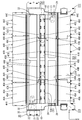
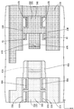
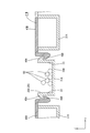
- the top view which shows a wiring module in the state where the left cover, the center cover, and the right cover were opened Partially enlarged plan view showing a state before the left connecting unit and the central connecting unit are connected.
- the power storage module 10 is mounted on a vehicle (not shown) such as an electric vehicle or a hybrid vehicle and used as a power source for driving the vehicle.
- the power storage module 10 includes a power storage element group 13 in which a plurality of power storage elements 12 having positive and negative electrode terminals (not shown) are arranged side by side. The plurality of electrode terminals are electrically connected by the wiring module 20 (see FIG. 1).
- the Z direction is upward
- the Y direction is front
- the X direction is right.
- symbol may be attached
- the electricity storage element 12 has a flat and substantially rectangular parallelepiped shape.
- a power generation element (not shown) is accommodated in the electric storage element 12.
- a pair of electrode terminals (not shown) are formed on the upper surface of the storage element 12 so as to protrude upward at positions near both ends in the longitudinal direction.
- One of the electrode terminals is a positive terminal and the other is a negative terminal.
- the electrode terminal constituting the positive electrode terminal and the electrode terminal constituting the negative electrode terminal have the same shape and size.
- the electrode terminal includes an electrode post (not shown) protruding in a round bar shape upward from a metal terminal block (not shown), and a thread is formed on the outer surface of the electrode post.
- the electricity storage element 12 is disposed so that adjacent electrode terminals have different polarities.
- the plurality of power storage elements 12 are arranged in the middle left-right direction to form a power storage element group 13.
- the wiring module 20 includes a plurality of metal bus bars 21 having a pair of terminal through holes 22 inserted and connected to the electrode posts of the positive electrode terminal and the negative electrode terminal of the power storage element 12, respectively.
- two bus bars 21 are shown, and the other bus bars 21 are omitted.
- the bus bar 21 is formed by pressing a metal plate made of copper, copper alloy, stainless steel (SUS), aluminum or the like into a predetermined shape, and has a substantially rectangular shape as a whole as shown in FIG. ing.
- the surface of the bus bar 21 may be plated with a metal such as tin or nickel.
- the bus bar 21 is formed with a pair of terminal through-holes 22 and 22 penetrating the bus bar 21 through which electrode posts of electrode terminals are inserted.
- the terminal through hole 22 is set slightly larger than the diameter of the electrode post.
- a nut (not shown) is screwed with the electrode post passing through the terminal through hole 22, and the bus bar 21 is sandwiched between the nut and the terminal block, so that the electrode terminal and the bus bar 21 are electrically connected. Connected.
- the bus bar 21 has a pair of long sides. One of the pair of long sides is provided with an electric wire connecting portion 23 that protrudes outward. An end portion of the electric wire 60 is connected to the electric wire connecting portion 23. Thereby, the bus bar 21 and the electric wire 60 are electrically connected.
- the electric wire 60 is a voltage detection line that detects the voltage of the storage element 12.
- the electric wire connection portion 23 and the electric wire 60 can be connected by a known method such as pressure bonding, pressure welding, ultrasonic welding, laser welding, resistance welding, or the like.
- the resin protector 30 is configured by connecting a plurality of connection units 31 along the connection direction (X-axis direction in the present embodiment).
- the resin protector 30 has an elongated shape in the left-right direction.
- the coupling unit 31 opens upward and holds a holding part 32 (an example of an opening) that holds and holds the bus bar 21 and an electric wire 60 connected to the bus bar 21.
- the holding part 32 is formed to open in the vertical direction. Accordingly, the bus bar 21 and the terminal block of the electric storage element 12 can be brought into contact with each other below the bus bar 21, and a nut can be screwed onto the electrode post from above the bus bar 21. It has become.
- the holding portion 32 holds the plurality of bus bars 21 side by side in a state of being insulated from each other.
- the connection unit 31 includes a left connection unit 31A (an example of a first connection unit) disposed at the left end in FIG. 2, a right connection unit 31C (an example of a first connection unit) disposed at the right end, and a left connection.
- a central connection unit 31B (an example of a second connection unit) disposed between the unit 31A and the right connection unit 31C.
- the left connecting unit 31A, the central connecting unit 31B, and the right connecting unit 31C may be described together as the connecting unit 31.
- the routing portion 35 provided in the left connection unit 31A is a left routing portion 35A (an example of a first routing portion), and the routing portion 35 provided in the right connection unit 31C is a right routing portion 35C (first An example of one routing unit), and the routing unit 35 provided in the central connection unit 31B is a central routing unit 35B (an example of a second routing unit).
- the left routing portion 35A, the central routing portion 35B, and the right routing portion 35C may be described as the routing portion 35 when collectively described.
- the routing unit 35 is provided along the arrangement direction (left-right direction) of the holding unit 32. By connecting a plurality of connecting units 31, the routing portions 35 formed in each connecting unit 31 are connected to each other.
- the left routing unit 35A of the left connecting unit 31A has a left bottom wall 34A (an example of a first bottom wall) and side walls 33A formed to rise on both side edges of the left bottom wall 34A.
- the right routing unit 35C of the right connecting unit 31C includes a right bottom wall 34C (an example of a first bottom wall) and a side wall 33C that is formed on both side edges of the right bottom wall 34C.
- the central routing portion 35B of the central coupling unit 31B has a central bottom wall 34B (an example of a first bottom wall) and side walls 33B that are formed to rise on both side edges of the central bottom wall 34B.
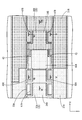
- a left engagement portion (an example of an engagement portion) that protrudes to the right is provided at the right end portion (the end portion on the central connection unit 31B side) of the left bottom wall 34A.
- the left engaging portion 40A has a substantially rectangular shape when viewed from above.
- a claw portion 41A that protrudes downward is formed on the lower surface of the left engagement portion 40A.
- a central engagement receiving portion 42B (an example of an engagement receiving portion) protruding leftward is provided at the left end portion (the end portion on the right connecting unit 31C side) of the central bottom wall 34B. Yes.
- the center engagement receiving portion 42B has a substantially rectangular field slightly smaller than the left engagement portion 40A when viewed from above.
- a claw portion 41B that protrudes upward and engages with a claw portion 41A provided in the left engagement portion 40A is formed on the upper surface of the central engagement receiving portion 42B.
- an overlapping portion 43 is formed at the left end portion of the center bottom wall 34B at the front portion and the rear portion, overlapping the left engaging portion 40A from above.
- the overlapping portion 43 has a substantially rectangular shape when viewed from above. The vicinity of the center of the overlapping portion 43 bulges downward, and is surely overlapped with the upper surface of the left engaging portion 40A.
- the left engaging portion 40A and the central engaging receiving portion 42B are formed in the thickness direction (vertical direction) of the left bottom wall 34A and the central bottom wall 34B. ) Are overlapping. Further, as described above, the overlapping portion 43 of the central coupling unit 31B overlaps with the front and rear end portions at the right end portion of the left engagement portion 40A from above.
- the claw portion 41A of the left engagement portion 40A engages with the claw portion 41B of the center engagement receiving portion 42B from the right side.
- the left connecting unit 31A and the center connecting unit 31B are prevented from coming off in the left-right direction. Since the overlapping portion 43 overlaps the left engaging portion 40A from above, the engagement between the claw portion 41A of the left engaging portion 40A and the claw portion 41B of the central engagement receiving portion 42B can be released. It is supposed to be suppressed.
- the left engaging portion 40A is formed to extend substantially parallel to the left bottom wall 34A.
- the center engagement receiving portion 42B is formed to extend substantially in parallel with the center bottom wall 34B. Therefore, it is suppressed that the thickness dimension of the up-down direction in the state which 40A of left engagement parts and the center engagement receiving part 42B engaged is increasing.
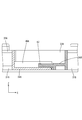
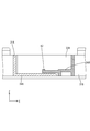
- the plurality of electric wires 60 are routed in a region in which the left bottom wall 34A, the left engagement portion 40A, and the central bottom wall 34B are the lower edge portions, and the upper end edges of the side walls 33A and 33B are the upper edge portions. Has been. In FIG. 6, a plurality of electric wires 60 are routed within the range of the height dimension H in the vertical direction.
- a left cover 45A (an example of a first cover) is provided at a front edge portion and a rear edge portion of the left connecting unit 31A via a left hinge portion 44A (an example of a first hinge portion).
- the left hinge portion 44A is pivotally provided.
- the left cover 45A is provided with a plurality of left cover lock portions 46A at intervals in the left-right direction on the edge opposite to the left hinge portion 44A.
- the left cover lock portion 46A is elastically engaged with a left cover lock receiving portion 47A provided in a region where the electric wire 60 is routed in the right routing portion. When the left cover lock portion 46A and the left cover lock receiving portion 47A are engaged, the left cover 45A closes the holding portion 32 of the left connecting unit 31A from above.
- a central cover 45B (an example of a second cover) is provided at a front edge portion and a rear edge portion of the central connection unit 31B via a central hinge portion 44B (an example of a second hinge portion).
- the center hinge part 44B is provided so as to be rotatable.
- the central cover 45B is provided with a plurality of central cover lock portions 46B at intervals in the left-right direction on the edge opposite to the central hinge portion 44B.
- the center cover lock portion 46B is elastically engaged with a center cover lock receiving portion 47B provided in a region where the electric wire 60 is routed in the right routing portion. When the center cover lock portion 46B and the center cover lock receiving portion 47B are engaged, the center cover 45B closes the holding portion 32 of the center connection unit 31B from above.
- a central unit lock portion 48B (an example of a unit lock portion) is provided at the left end portion of the central cover 45B provided at the front edge portion and the rear edge portion of the central connection unit 31B.
- the central unit lock portion 48B is a left unit lock receiving portion 49A (an example of a lock receiving portion) provided in a region where the electric wire 60 is routed in the right end portion of the left routing portion 35A of the left connecting unit 31A.
- the left connecting unit 31A and the central connecting unit 31B are connected to each other (see FIG. 8).
- the right connection unit 31C is formed symmetrically with the left connection unit 31A.
- “right” and “left” are replaced with respect to the description regarding the direction, and “A” is replaced with “C” regarding the sign.
- the description about the structure of the center connection unit 31B and the right connection unit 31C is abbreviate
- the members related to the right connection unit 31C are denoted by reference numerals in accordance with the above rules.
- the present embodiment is a wiring module 20 that is attached to a plurality of power storage elements 12 arranged, and includes a plurality of electric wires 60 and a plurality of connection units 31 in which the plurality of electric wires 60 are routed.
- the left connecting unit 31A has a left routing portion 35A in which at least one of the plurality of electric wires 60 is arranged, and among the plurality of connecting units 31, there are a plurality of central connecting units 31B adjacent to the left connecting unit 31A.
- the left wiring portion 35A is provided with a left engagement portion 40A
- the central wiring portion 35B is provided with a left engagement portion 40A.
- An engaging central engagement receiving portion 42B is provided, and the plurality of connecting units 31 are connected in a state where the left engaging portion 40A and the central engaging receiving portion 42B are engaged.
- the left engaging portion 40A and the central engaging receiving portion 42B for connecting the left connecting unit 31A and the central connecting unit 31B are respectively connected to the left routing portion 35A and the central routing portion 35B. Since it is provided, it is possible to sufficiently secure the wiring space for the electric wires 60 in the wiring module 20 as compared with the case where the engaging portion and the engaging receiving portion are provided at positions different from the wiring portion 35. .
- the left routing portion 35A has a groove shape and a left bottom wall 34A.
- the left bottom wall 34A is provided with a left engagement portion 40A
- the central routing portion 35B has a groove shape and has a central bottom wall 34B
- a central engagement receiving portion 42B is provided on the central bottom wall 34B.
- the left engagement unit 40A and the center engagement receiving portion 42B are connected to the left bottom wall 34A and the center bottom wall 34B in a state where the left connection unit 31A and the center connection unit 31B are connected. It overlaps in the thickness direction. Thereby, it can suppress further that the height dimension of the up-down direction of the wiring space of the electric wire 60 becomes large.
- the left connecting unit 31A is provided with the left cover 45A covering the holding portion 32 provided on the left connecting unit 31A via the left hinge portion 44A, and the central connecting unit 31B.
- a left unit lock receiving portion 49A that engages with the central unit lock portion 48B in a state where the cover 45B covers the holding portion 32 is provided in the left coupling unit 31A.
- the right connection unit 31C and the center connection unit 31B can be double-locked by the center cover 45B.
- the right coupling unit 31C and the central coupling unit 31B can be reliably coupled.
- the left engaging portion 40A is provided on the left bottom wall 34A, and the central engaging receiving portion 42B is provided on the central bottom wall 34B.
- the wall 34B may be provided with an engaging portion, and the left bottom wall 34A may be provided with an engaging receiving portion.
- the left engaging portion 40A is provided on the left bottom wall 34A
- the central engaging receiving portion 42B is provided on the central bottom wall 34B.
- the engagement portion may be provided on the side wall 33B, and the engagement receiving portion may be provided on the side wall 33B.
- the engagement portion may be provided on the side wall 33B, and the engagement receiving portion may be provided on the side wall 33A. Specification is also good.
- the holding unit 32 of the left coupling unit 31A is covered by the left cover 45A
- the holding unit 32 of the central coupling unit 31B is covered by the center cover 45B.
- the left cover 45A and the center cover 45B may be omitted.
- attaching a separate cover to the wiring module 20 are good.
- the three connecting units 31 of the left connecting unit 31A, the central connecting unit 31B, and the right connecting unit 31C are connected.
- the present invention is not limited to this, and the two connecting units 31 are connected. It is good also as a structure which carries out, and it is good also as a structure which four or more connection units 31 connect.
- Two adjacent connecting units among the plurality of connecting units can be a first unit and a second unit.
- the plurality of power storage elements 12 are connected in series.
- the present invention is not limited to this, and the plurality of power storage elements 12 may be connected in parallel.
- the present invention is not limited to this, and a capacitor may be used.
- Power storage device 20 Wiring module 31A: Left connecting unit 31B: Center connecting unit 31C: Right connecting unit 34A: Left bottom wall 34B: Center bottom wall 34C: Right bottom wall 35A: Left routing portion 35B: Center routing portion 35C: Right routing portion 40A: Left engagement portion 42B: Center engagement receiving portion 44A: Left hinge portion 44B: Center hinge portion 44C: Right hinge portion 45A: Left cover 45B: Center cover 45C: Right cover 48B: Center unit Lock part 49A: Left unit lock receiving part 60: Electric wire
Landscapes
- Chemical & Material Sciences (AREA)
- Chemical Kinetics & Catalysis (AREA)
- Electrochemistry (AREA)
- General Chemical & Material Sciences (AREA)
- Engineering & Computer Science (AREA)
- Power Engineering (AREA)
- Inorganic Chemistry (AREA)
- Manufacturing & Machinery (AREA)
- Microelectronics & Electronic Packaging (AREA)
- Connection Of Batteries Or Terminals (AREA)
- Battery Mounting, Suspending (AREA)
Priority Applications (2)
| Application Number | Priority Date | Filing Date | Title |
|---|---|---|---|
| US16/323,428 US10923292B2 (en) | 2016-08-09 | 2017-07-24 | Wiring module |
| CN201780047585.4A CN109565023B (zh) | 2016-08-09 | 2017-07-24 | 布线模块 |
Applications Claiming Priority (2)
| Application Number | Priority Date | Filing Date | Title |
|---|---|---|---|
| JP2016156610A JP6699438B2 (ja) | 2016-08-09 | 2016-08-09 | 配線モジュール |
| JP2016-156610 | 2016-08-09 |
Publications (1)
| Publication Number | Publication Date |
|---|---|
| WO2018030131A1 true WO2018030131A1 (ja) | 2018-02-15 |
Family
ID=61162239
Family Applications (1)
| Application Number | Title | Priority Date | Filing Date |
|---|---|---|---|
| PCT/JP2017/026630 Ceased WO2018030131A1 (ja) | 2016-08-09 | 2017-07-24 | 配線モジュール |
Country Status (4)
| Country | Link |
|---|---|
| US (1) | US10923292B2 (enExample) |
| JP (1) | JP6699438B2 (enExample) |
| CN (1) | CN109565023B (enExample) |
| WO (1) | WO2018030131A1 (enExample) |
Cited By (1)
| Publication number | Priority date | Publication date | Assignee | Title |
|---|---|---|---|---|
| JP2020087607A (ja) * | 2018-11-20 | 2020-06-04 | 日本メクトロン株式会社 | 支持部材及びバッテリモジュール |
Families Citing this family (2)
| Publication number | Priority date | Publication date | Assignee | Title |
|---|---|---|---|---|
| JP7182094B2 (ja) * | 2020-02-27 | 2022-12-02 | 矢崎総業株式会社 | バスバーモジュール |
| JPWO2025032975A1 (enExample) * | 2023-08-08 | 2025-02-13 |
Citations (3)
| Publication number | Priority date | Publication date | Assignee | Title |
|---|---|---|---|---|
| JP2011077031A (ja) * | 2009-09-07 | 2011-04-14 | Yazaki Corp | バスバモジュール、及び、このバスバモジュールを備えた電源装置 |
| JP2013161749A (ja) * | 2012-02-08 | 2013-08-19 | Auto Network Gijutsu Kenkyusho:Kk | 配線モジュール |
| JP2014107161A (ja) * | 2012-11-28 | 2014-06-09 | Yazaki Corp | バスバモジュール構造体 |
Family Cites Families (5)
| Publication number | Priority date | Publication date | Assignee | Title |
|---|---|---|---|---|
| JP5550291B2 (ja) * | 2009-09-17 | 2014-07-16 | 矢崎総業株式会社 | 電線配索体、バスバモジュール、及び、電源装置 |
| JP5734607B2 (ja) * | 2010-09-16 | 2015-06-17 | 矢崎総業株式会社 | バッテリ接続部材 |
| JP5673491B2 (ja) | 2011-10-31 | 2015-02-18 | 株式会社オートネットワーク技術研究所 | 電池配線モジュール |
| JP5772524B2 (ja) | 2011-11-11 | 2015-09-02 | 株式会社オートネットワーク技術研究所 | 電池配線モジュール |
| JP5978037B2 (ja) * | 2012-07-20 | 2016-08-24 | 矢崎総業株式会社 | バスバモジュール |
-
2016
- 2016-08-09 JP JP2016156610A patent/JP6699438B2/ja active Active
-
2017
- 2017-07-24 WO PCT/JP2017/026630 patent/WO2018030131A1/ja not_active Ceased
- 2017-07-24 US US16/323,428 patent/US10923292B2/en active Active
- 2017-07-24 CN CN201780047585.4A patent/CN109565023B/zh active Active
Patent Citations (3)
| Publication number | Priority date | Publication date | Assignee | Title |
|---|---|---|---|---|
| JP2011077031A (ja) * | 2009-09-07 | 2011-04-14 | Yazaki Corp | バスバモジュール、及び、このバスバモジュールを備えた電源装置 |
| JP2013161749A (ja) * | 2012-02-08 | 2013-08-19 | Auto Network Gijutsu Kenkyusho:Kk | 配線モジュール |
| JP2014107161A (ja) * | 2012-11-28 | 2014-06-09 | Yazaki Corp | バスバモジュール構造体 |
Cited By (2)
| Publication number | Priority date | Publication date | Assignee | Title |
|---|---|---|---|---|
| JP2020087607A (ja) * | 2018-11-20 | 2020-06-04 | 日本メクトロン株式会社 | 支持部材及びバッテリモジュール |
| JP7184606B2 (ja) | 2018-11-20 | 2022-12-06 | 日本メクトロン株式会社 | 支持部材及びバッテリモジュール |
Also Published As
| Publication number | Publication date |
|---|---|
| US10923292B2 (en) | 2021-02-16 |
| US20190355527A1 (en) | 2019-11-21 |
| CN109565023A (zh) | 2019-04-02 |
| JP6699438B2 (ja) | 2020-05-27 |
| JP2018026237A (ja) | 2018-02-15 |
| CN109565023B (zh) | 2021-08-20 |
Similar Documents
| Publication | Publication Date | Title |
|---|---|---|
| JP7099054B2 (ja) | 配線モジュール、及び蓄電モジュール | |
| JP6624427B2 (ja) | 蓄電モジュール | |
| JP6143108B2 (ja) | 蓄電モジュール | |
| WO2014013943A1 (ja) | 電池用配線モジュール | |
| US9837687B2 (en) | Battery module | |
| US20170352851A1 (en) | Electricity storage module | |
| WO2018043230A1 (ja) | 接続モジュール | |
| WO2013069756A1 (ja) | 配線モジュール | |
| JP5757252B2 (ja) | 配線モジュール | |
| JP5447724B1 (ja) | 配線モジュール | |
| JPWO2017047258A1 (ja) | 組電池 | |
| EP3367473B1 (en) | Wiring module | |
| JP6593166B2 (ja) | 配線モジュール | |
| CN109478629B (zh) | 布线模块 | |
| WO2018030131A1 (ja) | 配線モジュール | |
| JP6264217B2 (ja) | 配線モジュール | |
| WO2016140155A1 (ja) | 蓄電パック | |
| US11075430B2 (en) | Wiring module | |
| JP2019008875A (ja) | 電線接続バスバ及び導電モジュール | |
| JP2018026237A5 (enExample) | ||
| JP2017076491A (ja) | 二次電池モジュール | |
| WO2016017668A1 (ja) | 蓄電モジュール | |
| WO2016080212A1 (ja) | 蓄電モジュール |
Legal Events
| Date | Code | Title | Description |
|---|---|---|---|
| 121 | Ep: the epo has been informed by wipo that ep was designated in this application |
Ref document number: 17839204 Country of ref document: EP Kind code of ref document: A1 |
|
| NENP | Non-entry into the national phase |
Ref country code: DE |
|
| 122 | Ep: pct application non-entry in european phase |
Ref document number: 17839204 Country of ref document: EP Kind code of ref document: A1 |