WO2018030014A1 - Procédé de production d'ensemble piston et dispositif à fluide hydraulique - Google Patents
Procédé de production d'ensemble piston et dispositif à fluide hydraulique Download PDFInfo
- Publication number
- WO2018030014A1 WO2018030014A1 PCT/JP2017/023527 JP2017023527W WO2018030014A1 WO 2018030014 A1 WO2018030014 A1 WO 2018030014A1 JP 2017023527 W JP2017023527 W JP 2017023527W WO 2018030014 A1 WO2018030014 A1 WO 2018030014A1
- Authority
- WO
- WIPO (PCT)
- Prior art keywords
- piston
- fluid pressure
- pressure device
- piston member
- packing
- Prior art date
Links
Images


Classifications
-
- F—MECHANICAL ENGINEERING; LIGHTING; HEATING; WEAPONS; BLASTING
- F15—FLUID-PRESSURE ACTUATORS; HYDRAULICS OR PNEUMATICS IN GENERAL
- F15B—SYSTEMS ACTING BY MEANS OF FLUIDS IN GENERAL; FLUID-PRESSURE ACTUATORS, e.g. SERVOMOTORS; DETAILS OF FLUID-PRESSURE SYSTEMS, NOT OTHERWISE PROVIDED FOR
- F15B15/00—Fluid-actuated devices for displacing a member from one position to another; Gearing associated therewith
- F15B15/20—Other details, e.g. assembly with regulating devices
- F15B15/28—Means for indicating the position, e.g. end of stroke
- F15B15/2815—Position sensing, i.e. means for continuous measurement of position, e.g. LVDT
- F15B15/2861—Position sensing, i.e. means for continuous measurement of position, e.g. LVDT using magnetic means
-
- F—MECHANICAL ENGINEERING; LIGHTING; HEATING; WEAPONS; BLASTING
- F16—ENGINEERING ELEMENTS AND UNITS; GENERAL MEASURES FOR PRODUCING AND MAINTAINING EFFECTIVE FUNCTIONING OF MACHINES OR INSTALLATIONS; THERMAL INSULATION IN GENERAL
- F16J—PISTONS; CYLINDERS; SEALINGS
- F16J9/00—Piston-rings, e.g. non-metallic piston-rings, seats therefor; Ring sealings of similar construction
- F16J9/12—Details
- F16J9/20—Rings with special cross-section; Oil-scraping rings
-
- F—MECHANICAL ENGINEERING; LIGHTING; HEATING; WEAPONS; BLASTING
- F15—FLUID-PRESSURE ACTUATORS; HYDRAULICS OR PNEUMATICS IN GENERAL
- F15B—SYSTEMS ACTING BY MEANS OF FLUIDS IN GENERAL; FLUID-PRESSURE ACTUATORS, e.g. SERVOMOTORS; DETAILS OF FLUID-PRESSURE SYSTEMS, NOT OTHERWISE PROVIDED FOR
- F15B15/00—Fluid-actuated devices for displacing a member from one position to another; Gearing associated therewith
- F15B15/08—Characterised by the construction of the motor unit
- F15B15/14—Characterised by the construction of the motor unit of the straight-cylinder type
- F15B15/1423—Component parts; Constructional details
- F15B15/1447—Pistons; Piston to piston rod assemblies
- F15B15/1452—Piston sealings
-
- F—MECHANICAL ENGINEERING; LIGHTING; HEATING; WEAPONS; BLASTING
- F15—FLUID-PRESSURE ACTUATORS; HYDRAULICS OR PNEUMATICS IN GENERAL
- F15B—SYSTEMS ACTING BY MEANS OF FLUIDS IN GENERAL; FLUID-PRESSURE ACTUATORS, e.g. SERVOMOTORS; DETAILS OF FLUID-PRESSURE SYSTEMS, NOT OTHERWISE PROVIDED FOR
- F15B15/00—Fluid-actuated devices for displacing a member from one position to another; Gearing associated therewith
- F15B15/20—Other details, e.g. assembly with regulating devices
- F15B15/22—Other details, e.g. assembly with regulating devices for accelerating or decelerating the stroke
-
- F—MECHANICAL ENGINEERING; LIGHTING; HEATING; WEAPONS; BLASTING
- F16—ENGINEERING ELEMENTS AND UNITS; GENERAL MEASURES FOR PRODUCING AND MAINTAINING EFFECTIVE FUNCTIONING OF MACHINES OR INSTALLATIONS; THERMAL INSULATION IN GENERAL
- F16J—PISTONS; CYLINDERS; SEALINGS
- F16J1/00—Pistons; Trunk pistons; Plungers
- F16J1/005—Pistons; Trunk pistons; Plungers obtained by assembling several pieces
- F16J1/006—Pistons; Trunk pistons; Plungers obtained by assembling several pieces of different materials
- F16J1/008—Pistons; Trunk pistons; Plungers obtained by assembling several pieces of different materials with sealing lips
-
- F—MECHANICAL ENGINEERING; LIGHTING; HEATING; WEAPONS; BLASTING
- F16—ENGINEERING ELEMENTS AND UNITS; GENERAL MEASURES FOR PRODUCING AND MAINTAINING EFFECTIVE FUNCTIONING OF MACHINES OR INSTALLATIONS; THERMAL INSULATION IN GENERAL
- F16J—PISTONS; CYLINDERS; SEALINGS
- F16J1/00—Pistons; Trunk pistons; Plungers
- F16J1/10—Connection to driving members
- F16J1/12—Connection to driving members with piston-rods, e.g. rigid connections
Definitions
- the present invention relates to a fluid pressure device having a piston and a method for manufacturing a piston assembly.
- a fluid pressure device including a piston
- a fluid pressure cylinder having a piston that is displaced under the supply of pressure fluid is known as a conveying means (actuator) for a workpiece or the like.
- a fluid pressure cylinder has a cylinder tube, a piston disposed in the cylinder tube so as to be movable in the axial direction, and a piston rod connected to the piston (for example, see JP-A-2003-120602 below).
- a pressure fluid such as air is supplied into the cylinder tube
- the piston is displaced in the axial direction by being pushed by the pressure fluid, and the piston rod connected to the piston is also displaced in the axial direction.
- a packing mounting groove for mounting the packing is provided on the outer peripheral portion of the piston.
- the packing mounting groove is formed by grooving (cutting). Therefore, in the assembly process, in order to attach the packing to the piston, it is necessary to insert the packing into the piston in a state where the packing is pulled radially outward to expand the diameter. Such a mounting process is not easy to be automated by a robot, and it is difficult to improve productivity.
- the present invention has been made in view of such problems, and an object of the present invention is to provide a fluid pressure device and a method for manufacturing a piston assembly that can easily improve productivity.
- a fluid pressure device includes a body having a sliding hole therein, a piston unit capable of axial displacement within the sliding hole, and an axial projection from the piston unit.
- the piston unit includes a packing, and a piston main body formed of a plurality of members and provided with a packing mounting groove on which the packing is mounted. As a member, it has the 1st piston member projected outside from the piston rod, and the 2nd piston member arranged adjacent to the 1st piston member, and the packing is on the perimeter part of the 2nd piston member.
- the packing mounting groove is formed by a combination of at least two members among the plurality of members.
- the packing mounting groove is formed by a combination of a plurality of members. For this reason, productivity can be improved compared with the case where the groove part for mounting
- the first piston member and the second piston member are formed by casting, for example, it is possible to reduce the material used as compared with the case of groove processing, it is economical and resource saving can be achieved.
- the packing can be mounted on the piston body without expanding the diameter. Therefore, it is easy to automate the packing mounting process by the robot, and it is easy to improve productivity.
- the piston main body is disposed as the plurality of members on the side opposite to the first piston member and adjacent to the second piston member, and has an outer diameter larger than that of the second piston member.
- a fixing plate may be further provided, and the packing may be disposed between the first piston member and the fixing plate.
- the first piston member, the second piston member, and the fixing plate may be fastened in the axial direction by a connecting pin.
- the piston main body is disposed adjacent to the fixed plate and a wear ring made of a low friction material disposed so as to surround an outer peripheral portion of the first piston member as the plurality of members.
- the packing mounting groove may be formed by an outer peripheral surface of the second piston member, an end surface of the wear ring, and an end surface of the magnet.
- a gasket may be disposed between the first piston member, the second piston member, and the wear ring.
- the fixing plate may be provided with a damper made of an elastic material.
- a cavity may be formed between the second piston member and the piston rod.
- a damper made of an elastic material may be disposed between the inner peripheral portion of the second piston member and the outer peripheral portion of the piston rod along the axial direction of the piston rod.
- a cushion mechanism that forms a gas cushion when the piston unit approaches the stroke end to decelerate the piston unit is provided, and the cushion mechanism is a cushion joined to an outer peripheral surface of the piston rod. You may have a ring.
- the first piston member may protrude outward from one end of the piston rod, and the second piston member may protrude in an axial direction opposite to the piston rod.
- the second piston member may have an outer dimension smaller than that of the first piston member.
- the second piston member may have an outer dimension larger than that of the first piston member.
- the fluid pressure device may be configured as a fluid pressure cylinder, a valve device, a length measuring cylinder, a slide table, or a chuck device.
- the present invention is also a method of manufacturing a piston assembly comprising a piston unit having a packing mounted in a packing mounting groove and a piston rod protruding from the piston unit, wherein the first piston member is formed from the piston rod.
- the piston body including the packing mounting groove is configured by the plurality of members, and the packing mounting groove is formed by a combination of at least two members among the plurality of members. .
- the step of stacking the plurality of members may be performed with the tip of the piston rod member facing upward.
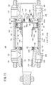
- FIG. 1 is a cross-sectional view of a fluid pressure cylinder according to a first embodiment of the present invention.
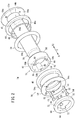
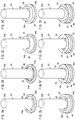
- FIG. 2 is a perspective view of a piston assembly of the fluid pressure cylinder shown in FIG. 3A is a first explanatory diagram of a method for manufacturing a piston assembly
- FIG. 3B is a second explanatory diagram of a method for manufacturing a piston assembly
- FIG. 3C is a third explanatory diagram of a method of manufacturing a piston assembly.
- 3D is a fourth explanatory view of a method for manufacturing a piston assembly
- FIG. 3E is a fifth explanatory view of a method for manufacturing the piston assembly
- FIG. 3F is a manufacturing method of the piston assembly.
- FIG. 3G is a seventh explanatory diagram of the manufacturing method of the piston assembly
- FIG. 3H is an eighth explanatory diagram of the manufacturing method of the piston assembly.
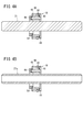
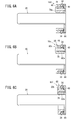
- FIG. 4A is an explanatory diagram of a first configuration example of a piston rod protruding in both directions
- FIG. 4B is an explanatory diagram of a second configuration example of a piston rod protruding in both directions.
- FIG. 5A is an explanatory diagram of a piston unit in which a spacer is arranged instead of a magnet
- FIG. 5B is an explanatory diagram of a piston unit in which another spacer is arranged instead of a magnet
- FIG. 5C is a wear ring omitted. It is explanatory drawing of the made piston unit.
- FIG. 5A is an explanatory diagram of a piston unit in which a spacer is arranged instead of a magnet
- FIG. 5B is an explanatory diagram of a piston unit in which another spacer is arranged instead of a magnet
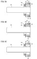
- FIG. 6A is an explanatory diagram of a first configuration example of a piston unit in which a fixing plate is omitted
- FIG. 6B is an explanatory diagram of a second configuration example of the piston unit, in which a fixing plate is omitted
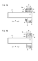
- FIG. 7A is an explanatory diagram of a first configuration example of a piston unit that employs a connecting pin having flanges formed at both ends
- FIG. 7B is a piston that employs a connecting pin having crimped portions formed at both ends. It is explanatory drawing of the 2nd structural example of a unit.
- FIG. 7A is an explanatory diagram of a first configuration example of a piston unit that employs a connecting pin having flanges formed at both ends
- FIG. 7B is a piston that employs a connecting pin having crimped portions formed at both ends. It is explanatory drawing of the 2nd structural
- FIG. 8 is an explanatory view of a piston unit arranged so as to protrude rearward from the piston rod.
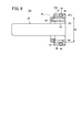
- FIG. 9 is an explanatory diagram of a piston unit including a second piston member having a larger diameter than the first piston member.
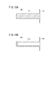
- FIG. 10A is an explanatory diagram of a first configuration example of a piston rod member in which the piston rod and the first piston member are integrally formed
- FIG. 10B is a piston rod in which the piston rod and the first piston member are integrally formed. It is explanatory drawing of the 2nd structural example of a member.
- FIG. 11 is a cross-sectional view of a fluid pressure cylinder according to a second embodiment of the present invention.
- FIG. 12 is a cross-sectional view of a fluid pressure cylinder according to a third embodiment of the present invention.
- FIG. 13 is a sectional view of a fluid pressure cylinder according to a fourth embodiment of the present invention.
- FIG. 14A is a cross-sectional view of a fluid pressure cylinder according to a fifth embodiment of the present invention, and
- FIG. 14B is a cross-sectional view of a fluid pressure cylinder according to a sixth embodiment of the present invention.
- a fluid pressure cylinder 10A shown in FIG. 1 includes a hollow cylindrical cylinder tube 12 (body), a head cover 14 disposed at one end of the cylinder tube 12, and the cylinder tube 12.
- a rod cover 16 disposed at the end, a piston unit 18 disposed in the cylinder tube 12 so as to be movable in the axial direction (arrow X direction), and a piston rod 20 coupled to the piston unit 18 are provided.
- the fluid pressure cylinder 10A is used as an actuator for conveying a workpiece, for example.
- the cylinder tube 12 is made of, for example, a metal material such as an aluminum alloy, and includes a cylinder that extends along the axial direction. In the present embodiment, the cylinder tube 12 is formed in a hollow cylindrical shape.
- the cylinder tube 12 includes a first port 12a provided on one end side in the axial direction (arrow X2 direction side), a second port 12b provided on the other end side in the axial direction (arrow X1 direction side), and a first A sliding hole 13 (cylinder chamber) communicating with the port 12a and the second port 12b is provided.
- the head cover 14 is, for example, a plate-like body made of the same metal material as the cylinder tube 12, and is provided so as to close one end portion (end portion on the arrow X2 direction side) of the cylinder tube 12.
- One end of the cylinder tube 12 is hermetically closed by the head cover 14.
- a first damper 22 is provided on the inner wall surface 14 a of the head cover 14.
- the first damper 22 is made of an elastic material such as a rubber material or an elastomer material, for example. Examples of the constituent material of the first damper 22 include urethane.
- the 1st damper 22 is formed in the ring shape which has the through-hole 22a in center part.
- a bulging portion 23 that bulges toward the rod cover 16 side (piston rod 20 and piston unit 18 side) is provided on the center side of the first damper 22.
- the thickness of the portion where the bulging portion 23 is provided is thicker than the thickness of the outer peripheral portion radially outside the bulging portion 23.
- the rod cover 16 is, for example, a circular ring-shaped member made of the same metal material as the cylinder tube 12, and is provided so as to close the other end (the end on the arrow X1 direction side) of the cylinder tube 12. ing.
- An outer annular groove 24 is formed on the outer periphery of the rod cover 16.
- An outer seal member 26 made of an elastic material that seals between the outer peripheral surface of the rod cover 16 and the inner peripheral surface of the sliding hole 13 is attached to the outer annular groove 24.
- An inner annular groove 28 is formed on the inner periphery of the rod cover 16.
- An inner seal member 30 made of an elastic material that seals between the inner peripheral surface of the rod cover 16 and the outer peripheral surface of the piston rod 20 is attached to the inner annular groove 28.
- the rod cover 16 is locked by a stopper 32 fixed to the inner peripheral portion on the other end side of the cylinder tube 12.
- the piston unit 18 is accommodated in the cylinder tube 12 (sliding hole 13) so as to be slidable in the axial direction, and the first pressure chamber 13a on the first port 12a side and the second port 12b side in the sliding hole 13 are accommodated. It is partitioned off from the second pressure chamber 13b.
- the piston unit 18 is connected to one end 20 a (hereinafter referred to as “base end 20 a”) of the piston rod 20.
- the piston unit 18 includes a packing 34 and a piston main body 38 provided with a packing mounting groove 36.
- the piston body 38 includes a first piston member 40, a second piston member 42, a wear ring 44 (support member), a gasket 46, a magnet 48, and a fixing plate 50. And a plurality of connecting pins 52.
- the first piston member 40 is a plate-shaped and ring-shaped member that protrudes radially outward from the base end portion 20a of the piston rod 20.
- the outer diameter of the first piston member 40 is larger than the outer diameter of the piston rod 20.
- the inner end edge of the first piston member 40 is joined to the outer periphery of the base end portion 20 a of the piston rod 20.
- attachment, etc. are mentioned, for example.
- the first piston member 40 is formed with a plurality of (three in this embodiment) pin holes 54a penetrating the first piston member 40 in the plate thickness direction.
- the plurality of pin holes 54a are formed at equal intervals in the circumferential direction.
- the constituent material of the first piston member 40 examples include metal materials such as carbon steel, stainless steel, and aluminum alloy, and hard resin. When the first piston member 40 and the piston rod 20 are joined by welding, the first piston member 40 may be made of the same metal material as that of the piston rod 20 in order to ensure good joint strength.
- the second piston member 42 is a hollow cylindrical member having a rod insertion hole 43 inside thereof, and is disposed adjacent to the first piston member 40.
- the second piston member 42 has a peripheral wall portion 56 that surrounds the rod insertion hole 43.
- the second piston member 42 is disposed adjacent to the tip 20b side of the piston rod 20 of the first piston member 40 so as to surround the piston rod 20.
- the outer diameter of the second piston member 42 is smaller than the outer diameter of the first piston member 40.
- a diameter-reduced portion 42a is provided at one end of the second piston member 42, and a gasket 46 is disposed in the diameter-reduced portion 42a.
- the peripheral wall portion 56 of the second piston member 42 is provided with the same number (three in this embodiment) of pin insertion holes 54b as the plurality of pin holes 54a provided in the first piston member 40.
- the pin insertion hole 54b penetrates the peripheral wall portion 56 of the second piston member 42 in the axial direction (arrow X direction). Similar to the plurality of pin holes 54a, the plurality of pin insertion holes 54b are formed at equal intervals in the circumferential direction.
- the inner periphery of the second piston member 42 is provided with a plurality of recesses 58 that are recessed radially outward at intervals in the circumferential direction, and a plurality of protrusions that protrude radially inward between these recesses 58.
- a portion 60 is provided.
- the pin insertion hole 54b described above is formed in each of the convex portions 60.
- the top (inner end) of the convex portion 60 is separated from the outer peripheral surface of the piston rod 20.
- the top portion (inner end) of the convex portion 60 may be in contact with the outer peripheral surface of the piston rod 20.
- a cavity 62 (see FIG. 1) is formed between the inner peripheral portion of the second piston member 42 and the outer peripheral surface of the piston rod 20.
- the cavity 62 is formed in an annular shape that goes around the piston rod 20.
- the top part (inner end) of the convex part 60 contacts the outer peripheral surface of the piston rod 20 a plurality of cavities 62 are formed at intervals in the circumferential direction of the piston rod 20.
- the first piston member 40 and the second piston member 42 are molded by casting.
- molding method of the 1st piston member 40 and the 2nd piston member 42 is not limited to casting, Other methods, for example, cutting etc., may be sufficient.
- the packing 34 is a ring-shaped seal member (for example, an O-ring) made of an elastic body attached to the outer peripheral portion of the second piston member 42.
- the constituent material of the packing 34 include elastic materials such as rubber materials and elastomer materials.
- the outer diameter of the packing 34 is determined in a state where the packing 34 is in a natural state (a state in which the packing 34 is not disposed in the sliding hole 13 and is not elastically compressed radially inward) and a state in which the packing 34 is disposed in the sliding hole 13. It is larger than the outer diameter of the ring 44, the magnet 48 and the yoke.
- the outer peripheral portion of the packing 34 is in airtight or liquid tight contact with the inner peripheral surface of the sliding hole 13 over the entire circumference.
- the inner peripheral portion of the packing 34 is in airtight or liquid tight contact with the outer peripheral surface of the second piston member 42 over the entire periphery.
- the packing 34 is sandwiched between the inner peripheral surface of the sliding hole 13 and the outer peripheral surface of the second piston member 42 and is elastically compressed in the radial direction.
- the seal 34 seals between the outer peripheral surface of the piston unit 18 and the inner peripheral surface of the sliding hole 13, and the first pressure chamber 13a and the second pressure chamber 13b in the sliding hole 13 are partitioned in an airtight or liquid tight manner. ing.
- the wear ring 44 is configured so that the outer peripheral surface of the first piston member 40 becomes the inner peripheral surface of the sliding hole 13 when a large lateral load is applied to the piston unit 18 in the direction perpendicular to the axial direction during the operation of the fluid pressure cylinder 10A. It is a member for preventing contact.
- the wear ring 44 is a circular ring-shaped member, and is attached to the outer peripheral portion of the first piston member 40 so as to surround the outer peripheral portion of the first piston member 40.
- the wear ring 44 is in contact with the end surface (the end surface on the arrow X1 direction side) of the first piston member 40 and extends along the radial direction, and the outer peripheral surface of the first piston member 40. And an axial portion 44b extending along the axial direction.
- the wear ring 44 (specifically, the radial portion 44a) is in contact with one side portion (side portion on the arrow X2 direction side) of the packing 34.
- the inner diameter of the radial portion 44 a is smaller than the outer diameter of the first piston member 40.
- the axial portion 44b extends in the axial direction from the outer end portion of the radial portion 44a.
- the outer diameter of the wear ring 44 (the outer diameter of the axial portion 44b) is larger than the outer diameters of the first piston member 40, the magnet 48, and the yoke.
- Wear ring 44 is made of a low friction material.
- the friction coefficient between the wear ring 44 and the inner peripheral surface of the sliding hole 13 is smaller than the friction coefficient between the packing 34 and the inner peripheral surface of the sliding hole 13.
- Examples of such a low friction material include a synthetic resin material having both low friction and wear resistance such as tetrafluoroethylene (PTFE), a metal material (for example, bearing steel), and the like.
- the gasket 46 is a circular ring-shaped member made of an elastic body disposed between the first piston member 40, the second piston member 42, and the wear ring 44.
- the gasket 46 can be made of the same material as the packing 34.
- the gasket 46 is in airtight or liquid tight contact with the first piston member 40, the second piston member 42, and the wear ring 44.
- the gasket 46 is in close contact with the end surface of the first piston member 40 on the second piston member 42 side, in close contact with the outer peripheral surface of the reduced diameter portion 42 a of the second piston member 42, and the inner periphery of the wear ring 44. It is in close contact with the surface (inner peripheral surface of the radial portion 44a).
- the space between the first piston member 40 and the second piston member 42, the space between the first piston member 40 and the wear ring 44, and the space between the second piston member 42 and the wear ring 44 are airtight. Or it is sealed fluid-tight.
- the magnet 48 is a circular ring-shaped member, and is attached to the outer peripheral portion of the first piston member 40 so as to surround the outer peripheral portion of the first piston member 40.
- the magnet 48 is disposed adjacent to the packing 34 on the side opposite to the wear ring 44 (arrow X1 direction side), and is in contact with the other side portion of the packing 34.
- the magnet 48 is, for example, a ferrite magnet or a rare earth magnet.
- a magnetic sensor (not shown) is attached to the outer surface of the cylinder tube 12 at positions corresponding to both stroke ends of the piston unit 18. The operating position of the piston unit 18 is detected by sensing the magnetism generated by the magnet 48 with a magnetic sensor.
- the end surface of the wear ring 44 (the end surface on the arrow X1 direction side), the end surface of the magnet 48 (the end surface on the arrow X2 direction side), and the outer peripheral surface of the piston rod 20 are recessed radially inward and annularly extended in the circumferential direction.
- An existing packing mounting groove 36 is formed.
- the packing 34 is mounted in the packing mounting groove 36.
- the fixing plate 50 is a circular ring-shaped member, and holds the wear ring 44, the packing 34, and the magnet 48 in cooperation with the first piston member 40.
- the fixed plate 50 surrounds the piston rod 20. Specifically, the fixed plate 50 abuts against the end surface (end surface on the arrow X1 direction side) opposite to the packing 34 of the magnet 48 and the end surface (arrow indicated by the arrow) of the second piston member 42 on the opposite side to the first piston member 40. X1 direction side end surface).
- the constituent material of the fixing plate 50 examples include metal materials such as carbon steel (rolled steel, etc.), stainless steel, aluminum alloy, and hard resin materials.
- the fixed plate 50 may be a member made of a magnetic material such as rolled steel so as to function also as a yoke.
- the fixing plate 50 is formed with the same number (three in this embodiment) of pin holes 54c as the plurality of pin insertion holes 54b provided in the second piston member 42.
- the plurality of pin holes 54c penetrates the fixed plate 50 in the plate thickness direction.
- the plurality of pin holes 54c are formed at equal intervals in the circumferential direction in the same manner as the plurality of pin insertion holes 54b provided in the second piston member 42.
- the plurality of connecting pins 52 fasten the first piston member 40, the second piston member 42, and the fixing plate 50 disposed adjacent to each other in the axial direction in the axial direction, and these members are fixed to each other and integrated. .
- the wear ring 44, packing 34, and magnet 48 described above are held between the first piston member 40 and the fixed plate 50.
- Each connecting pin 52 is inserted into a pin hole 54 a provided in the first piston member 40, a pin insertion hole 54 b provided in the second piston member 42, and a pin hole 54 c provided in the fixing plate 50.
- the first piston member 40 and the fixed plate 50 are engaged.
- each connecting pin 52 At one end portion (end portion on the arrow X1 direction side) of each connecting pin 52, a flange portion 64 having a diameter larger than that of the shaft portion 53 of the connecting pin 52 is provided.
- the outer diameter of the collar portion 64 is larger than the diameter of the pin hole 54 c provided in the fixed plate 50. Thereby, the collar part 64 is engaged with the peripheral part of the pin hole 54c in the fixing plate 50.
- the other end portion (the end portion on the arrow X2 direction side) of each connecting pin 52 is provided with a crimping portion 66 (see FIG. 1) whose diameter is larger than that of the shaft portion 53.
- the caulking portion 66 is formed by pressing the other end portion of the connecting pin 52 in the axial direction to cause plastic deformation.
- the caulking portion 66 is formed in a taper shape following the hole shape of the pin hole 54a, and is engaged with the pin hole 54a.
- the caulking portion 66 may be formed in a plate shape that protrudes perpendicularly to the shaft portion 53 of the connecting pin 52, and may engage with a peripheral portion of the pin hole 54 a in the first piston member 40.
- a second damper 68 made of an elastic member is attached to the end of the piston unit 18 opposite to the head cover 14 (the end on the arrow X1 direction side).
- the second damper 68 can be made of the same material as that of the first damper 22.
- the second damper 68 is formed in a circular ring shape and is disposed so as to surround the piston rod 20.
- the second damper 68 is attached to the fixed plate 50.
- the outer diameter of the second damper 68 is smaller than the outer diameter of the fixed plate 50.
- An engaging groove 70 that is recessed radially inward is provided on the inner peripheral side of the end portion of the second damper 68 on the fixed plate 50 side.
- a plurality of engagement grooves 70 are provided at intervals in the circumferential direction.
- the second damper 68 is supported on the fixed plate 50 by the engagement groove 70 engaging with the inner edge of the fixed plate 50.
- a plurality of concave cutouts 72 are formed on the end surface of the second damper 68 on the fixed plate 50 side at intervals in the circumferential direction. Each notch 72 accommodates the collar portion 64 of each connecting pin 52 described above.
- either one of the first damper 22 and the second damper 68 may be omitted, or both the first damper 22 and the second damper 68 may be omitted.
- the piston rod 20 is a columnar (columnar) member extending along the axial direction of the sliding hole 13.
- the first piston member 40 described above is joined to the base end portion 20a of the piston rod 20.
- the piston rod 20 passes through the rod cover 16.
- a distal end portion 20 b that is an end portion on the opposite side of the proximal end portion 20 a of the piston rod 20 is exposed to the outside of the sliding hole 13.
- the piston unit 74 and the piston rod 20 constitute a piston assembly 74.
- Examples of the constituent material of the piston rod 20 include the materials (carbon steel and the like) mentioned as the constituent material of the first piston member 40.
- the piston rod 20 may be made of the same material as that of the first piston member 40, or may be made of a material different from that of the first piston member 40.
- the piston rod 20 to which the first piston member 40 is joined by welding or the like is prepared.
- the piston rod 20 provided with the first piston member 40, the second piston member 42, the wear ring 44, the gasket 46, the packing 34, the magnet 48, the fixing plate 50, the connecting pin 52, and the second damper described above An assembling step (FIGS. 3A to 3H) in which 68 is moved in the axial direction and assembled is performed. Thereby, the piston assembly 74 is obtained.
- the wear ring 44, the gasket 46, and the piston rod 20 are inserted into the wear ring 44, the gasket 46, and the second piston member 42, respectively.
- the 2nd piston member 42 is moved toward the base end part 20a side of the piston rod 20 in order.
- the piston rod 20 is held with the tip 20b of the piston rod 20 facing upward, and the wear ring 44, the gasket 46, and the The second piston member 42 is stacked.
- the wear ring 44 is disposed on the outer periphery of the first piston member 40, one end of the second piston member 42 abuts on the first piston member 40, and the first piston member 40, the second piston member 42, and The gasket 46 is placed between the wear rings 44.
- the plurality of pin holes 54 a provided in the first piston member 40, the plurality of pin insertion holes 54 b provided in the second piston member 42, and the plurality of pin holes 54 c provided in the fixing plate 50 are The phases in the circumferential direction are matched with each other.
- the packing 34 and the magnet 48 are sequentially attached to the outer peripheral portion of the second piston member 42.
- the packing 34 can be easily mounted on the outer peripheral portion of the second piston member 42 without being pulled radially outward to increase the diameter. it can.
- an annular magnet is formed by joining a plurality of magnet pieces on the outer periphery of the piston by bonding.
- the second piston member is maintained while the magnet 48 remains annular. 42 can be assembled.
- the fixing plate 50 is brought into contact with the other end portion of the second piston member 42.
- a plurality of connecting pins 52 are connected to a plurality of pin holes 54c provided in the fixing plate 50, as shown in FIG.
- the plurality of pin insertion holes 54 b provided in the second piston member 42 and the plurality of pin holes 54 a provided in the first piston member 40 are inserted.
- the end of each connecting pin 52 protruding from the first piston member 40 is pressed and plastically deformed to increase the diameter, thereby forming a crimping portion 66 (see FIG. 1).
- first piston member 40, the second piston member 42, and the fixing plate 50 are firmly fastened in the axial direction by the plurality of connecting pins 52, and formed by the second piston member 42, the wear ring 44, and the magnet 48.
- the packing 34 is mounted in the packing mounting groove 36.
- the second damper 68 is attached to the fixed plate 50.
- the second damper 68 is made of an elastic member that is easily deformed, by pressing the second damper 68 against the fixing plate 50, the engagement groove 70 ( Can be easily engaged. Therefore, it is easy to attach the second damper 68 to the fixed plate 50.
- the fluid pressure cylinder 10A moves the piston unit 18 in the axial direction in the sliding hole 13 by the action of the pressure fluid (for example, compressed air) introduced through the first port 12a or the second port 12b. Thereby, the piston rod 20 connected to the piston unit 18 moves forward and backward.
- the pressure fluid for example, compressed air
- the second port 12b is opened to the atmosphere, and pressure fluid is supplied from a pressure fluid supply source (not shown) through the first port 12a.
- One pressure chamber 13a is supplied.
- the piston unit 18 is pushed toward the rod cover 16 by the pressure fluid.
- the piston unit 18 is displaced (advanced) together with the piston rod 20 toward the rod cover 16 side.
- the forward movement of the piston unit 18 is stopped when the second damper 68 abuts against the end surface of the rod cover 16.
- the second damper 68 made of an elastic material.
- the first port 12a is opened to the atmosphere, and pressure fluid is supplied from a pressure fluid supply source (not shown) through the second port 12b to the second pressure chamber. 13b. Then, the piston unit 18 is pushed toward the head cover 14 by the pressure fluid. As a result, the piston unit 18 is displaced toward the head cover 14 side. Then, when the piston rod 20 and the first piston member 40 abut against the first damper 22 (the bulging portion 23), the retreating operation of the piston unit 18 is stopped.
- the first damper 22 made of an elastic material prevents the piston unit 18 and the head cover 14 from directly contacting each other. Thereby, it is possible to effectively prevent or suppress the generation of impact and impact sound associated with the piston unit 18 reaching the retracted position (stroke end on the head cover 14 side).
- a packing mounting groove 36 is formed by a combination of a plurality of members (second piston member 42, wear ring 44 and magnet 48). For this reason, productivity can be improved compared with the case where the groove part for mounting
- the first piston member 40 and the second piston member 42 are molded by casting, the material used can be reduced as compared with the case of groove processing, so that it is economical and resource saving can be achieved. it can.
- the packing mounting groove 36 is formed by a combination of a plurality of members. Therefore, in the assembly process, the packing 34 can be mounted on the piston main body 38 without increasing its diameter. Therefore, automation of the packing mounting process by the robot is easy.
- members other than the packing 34 can be assembled to the piston rod 20 by being moved in the axial direction and stacked with respect to the piston rod 20 provided with the first piston member 40. Therefore, the assembly process of the piston unit 18 (piston assembly 74) can be easily automated, and the productivity can be improved.
- the inner peripheral portion of the second piston member 42 is separated from the outer peripheral surface of the piston rod 20, and a cavity 62 is formed between the second piston member 42 and the piston rod 20. .
- weight reduction of the piston unit 18 can be achieved through weight reduction of the second piston member 42.
- the amount of pressure fluid consumed can be reduced, and energy saving can be achieved.
- the piston rod 20 that protrudes only on one side of the piston unit 18 is employed, but as shown in FIGS. 4A and 4B, the piston rods 21 that protrude on both sides of the piston unit 18, 21a may be employed.
- the piston rod 21 shown in FIG. 4A has a solid structure
- the piston rod 21a shown in FIG. 4B has a hollow structure
- the piston unit 18 can be joined to the outer peripheral surface of the piston rods 21 and 21a by welding or an adhesive.
- Each of the piston rods 21 and 21a may be composed of a first rod portion and a second rod portion connected in the axial direction.
- the connecting method of the first rod part and the second rod part may be screwing (screwing), welding, adhesion, or the like.
- the piston unit 18 is not limited to the above-described configuration, and various configurations such as the piston units 18a to 18j shown in FIGS. 5A to 9 can be adopted. Also with these configurations, the piston units 18a to 18j to which the packing 34 is attached can be assembled by stacking a plurality of parts in the axial direction. The piston units 18a to 18j can also be employed in fluid pressure cylinders 10B to 10F according to second to sixth embodiments described later.
- a spacer 76 is disposed adjacent to the packing 34 instead of the magnet 48 (see FIG. 1).
- the packing mounting groove 36 is formed by the second piston member 42, the wear ring 44, and the spacer 76.
- the spacer 76 has a quadrangular cross section.
- the packing mounting groove 36 is formed by the second piston member 42, the wear ring 44, and the spacer 76a.
- the spacer 76a of FIG. 5B has a square U-shaped cross section.
- the fixing plate 50 may be a member made of a nonmagnetic material.
- the wear ring 44 (see FIG. 1) is omitted.
- the packing mounting groove 36 is formed by the first piston member 40, the second piston member 42 and the magnet 48. Accordingly, the packing 34 is disposed adjacent to the first piston member 40 and is held between the first piston member 40 and the magnet 48.
- the fixing plate 50 (see FIG. 1 and the like) functioning as a yoke is omitted.
- the flange portion 78a of the connecting pin 78 is larger in diameter than the flange portion 64 (see FIG. 2) of the connecting pin 52 described above and larger than the outer diameter of the second piston member 42.
- the magnet 48 is in contact (engagement) with the end surface opposite to the packing 34. For this reason, the fall of the magnet 48 from the 2nd piston member 42 is prevented by the collar part 78a. That is, in the piston unit 18 d, the flange portion 78 a of the connecting pin 78 also functions as a fixing plate that holds the magnet 48.
- the second piston member 80 has a flange 80b that protrudes radially outward from the base 80a on which the packing 34 and the magnet 48 are mounted.
- the flange 80b is in contact with the end surface of the magnet 48 opposite to the packing 34. For this reason, dropping off of the magnet 48 from the second piston member 80 is prevented by the flange portion 80b. That is, in the piston unit 18 e, the flange portion 80 b of the second piston member 80 also functions as a fixing plate that holds the magnet 48.
- the second piston member 82 has a flange portion 82b that protrudes radially outward from the base portion 82a on which the packing 34 is mounted on the outer periphery thereof.
- the collar portion 82 b is in contact with the packing 34.
- the packing mounting groove 36 is formed by the first piston member 40 and the second piston member 82. The packing 34 is held between the first piston member 40 and the flange portion 82b.
- the end of the connecting pin 84 on the first piston member 40 side (arrow X2 direction side) is formed as a plate-like flange portion 84a that projects perpendicularly to the shaft portion 53.
- the connecting pin 84 is obtained by replacing the caulking portion 66 (see FIG. 1) of the connecting pin 52 described above with a flange portion 84a, and has a configuration similar to that of the connecting pin 52 except for the flange portion 84a. .
- the end of the connecting pin 86 on the arrow X1 direction side is formed as a crimping portion 86a whose diameter is increased in a tapered shape with respect to the shaft portion 53. That is, the connecting pin 86 is obtained by replacing the flange portion 64 (see FIG. 2) of the connecting pin 52 described above with a caulking portion 86a, and has a configuration similar to that of the connecting pin 52 except for the caulking portion 86a. .
- the total length Lh2 of the piston assembly 74a composed of the piston rod 88 and the piston unit 18i shown in FIG. 8 is the same as the total length (the same as the length L1 of the piston rod 20) of the piston assembly 74 shown in FIG.
- the length L2 of the piston rod 88 shown in FIG. 8 is shorter than the length L1 of the piston rod 20 shown in FIG.
- the length L2 of the piston rod 88 can be shortened as compared with the piston assembly 74 shown in FIG. Therefore, it is possible to reduce the weight of the piston rod 88, which is a movable part, and to reduce the consumption of pressure fluid and save energy.
- the outer diameter (planar dimension) of the second piston member 92 is larger than the outer diameter (planar dimension) of the first piston member 90.
- the outer diameter D2 of the first piston member 90 is smaller than the outer diameter D1 of the first piston member 40 shown in FIG.
- the second piston member 92 has an annular large-diameter portion 92b having an outer diameter larger than that of the base portion 92a while the packing 34 and the magnet 48 are disposed on the outer peripheral portion of the base portion 92a.
- the large diameter portion 92 b surrounds the first piston member 90.
- the wear ring 44 is disposed on the outer peripheral portion of the large diameter portion 92b.
- a packing mounting groove is formed by a combination of a plurality of members (second piston member 92, wear ring 44 and magnet 48), similarly to the case where the piston unit 18 shown in FIG. 1 is adopted. 36 is formed. Therefore, as in the case where the piston unit 18 shown in FIG. 1 is employed, productivity can be improved, and a plurality of parts are stacked in the axial direction, whereby the piston assembly 74b including the piston unit 18j is formed. Can be easily assembled. Therefore, the assembly process of the piston assembly 74b including the piston unit 18j can be easily automated.
- piston rod 20 and the first piston member 40 shown in FIG. 1 the piston rod 20 and the first piston member 40 produced as separate parts are joined by welding or the like.
- a piston rod member 94a may be employed.
- the piston rod members 94, 94a can be formed by forging or casting.
- the piston rod member 94 shown in FIG. 10A has a solid structure piston rod 20 and a first piston member 40 that protrudes radially outward from one end of the piston rod 20 continuously.
- the piston rod member 94a shown in FIG. 10B includes a hollow piston rod 21b and a first piston member 40 that protrudes radially outward from one end of the piston rod 21b.
- a fluid pressure cylinder 10B according to the second embodiment shown in FIG. 11 replaces the first damper 22 and second damper 68 in the fluid pressure cylinder 10A shown in FIG. 2 damper 98 is adopted. Similar to the first damper 22 and the second damper 68, the first damper 96 and the second damper 98 are made of an elastic material such as a rubber material. The configuration of the fluid pressure cylinder 10B other than the first damper 96 and the second damper 98 is the same as that of the fluid pressure cylinder 10A.
- the first damper 96 prevents or suppresses the generation of impact and impact sound by contacting the piston unit 18 when the piston unit 18 moves in the direction of the arrow X2 and reaches the retracted position.
- the first damper 96 is formed in a ring shape and is attached to the inner wall surface 14 a of the head cover 14.
- the inner diameter of the first damper 96 is larger than the outer diameter of the piston rod 20.
- the outer diameter of the first damper 96 is substantially the same as the outer diameter of the piston unit 18. For this reason, compared with the 1st damper 22 shown in Drawing 1, the 1st damper 96 can earn an effective volume. Therefore, the first damper 96 can more effectively prevent or suppress the generation of impact and impact sound when the piston unit 18 reaches the retracted position.
- the second damper 98 prevents or suppresses the generation of impact and impact sound by contacting the head cover 14 when the piston unit 18 moves in the direction of the arrow X1 and reaches the forward position.
- the second damper 98 is formed in a ring shape surrounding the piston rod 20 and is disposed between the outer peripheral portion of the piston rod 20 and the inner peripheral portion of the second piston member 42 along the axial direction of the piston rod 20. Has been.
- the inner peripheral portion of the second damper 98 is in contact with the outer peripheral portion of the piston rod 20, and the second damper 98 is supported by the piston rod 20.
- the inner diameter of the second damper 98 before the piston rod 20 is inserted (before assembly) is smaller than the outer diameter of the piston rod 20. For this reason, in the assembled state, the second damper 98 is in pressure contact with the outer peripheral portion of the piston rod 20 by the elastic restoring force of the second damper 98 itself.
- the end of the second damper 98 on the head cover 14 side (arrow X2 direction side) in contact with the first piston member 40, the end of the second damper 98 on the rod cover 16 side (arrow X1 direction side) is
- the piston body 38 (specifically, the flange 64 of the connecting pin 52) protrudes toward the rod cover 16 side.
- the second damper 98 may be separated from the first piston member 40 during operation of the fluid pressure cylinder 10B (during reciprocation of the piston unit 18).
- a moderately sized gap is formed between the outer periphery of the second damper 98 and the inner periphery of the second piston member 42. For this reason, when the second damper 98 receives an axial compressive load, the second damper 98 is elastically deformed so as to shorten in the axial direction due to an increase in outer diameter. Therefore, the second damper 98 can exhibit the shock absorbing ability without any trouble.
- the second damper 98 has a smaller outer diameter than that of the second damper 68 shown in FIG. 1, but can have a large axial length, so that it has an effective volume that affects the shock absorbing capacity. be able to. Therefore, the second damper 98 can more effectively prevent or suppress the generation of impact and impact noise when the piston unit 18 reaches the forward position.
- the outer peripheral shape of the second damper 98 is formed along the inner peripheral shape of the second piston member 42. That is, the outer peripheral portion of the second damper 98 is formed in a wave shape having a plurality of concave portions 98a into which the plurality of convex portions 60 (see also FIG. 2) of the second piston member 42 are inserted. With this configuration, the volume of the second damper 98 can be increased as much as possible, and the shock absorbing capacity can be further increased.
- a fluid pressure cylinder 10C according to the third embodiment shown in FIG. 12 is opposed to the piston unit 18 of the rod cover 16 instead of the second damper 68 provided in the piston unit 18 in the fluid pressure cylinder 10A shown in FIG.
- the second damper 100 is provided on the side surface 16a. When the piston unit 18 moves in the direction of the arrow X1 and reaches the forward position, the second damper 100 prevents or suppresses the generation of impact and impact sound by contacting the piston unit 18.
- Other configurations of the fluid pressure cylinder 10C are the same as those of the fluid pressure cylinder 10A.
- a fluid pressure cylinder 10D according to the fourth embodiment shown in FIG. 13 includes a hollow cylindrical cylinder tube 102 (body), a head cover 104 disposed at one end of the cylinder tube 102, and the other end of the cylinder tube 102. And a rod cover 106 disposed.
- the fluid pressure cylinder 10D further includes a piston unit 18 disposed in the cylinder tube 102 so as to be movable in the axial direction (arrow X direction), a piston rod 108 coupled to the piston unit 18, and one of the piston unit 18 and And a cushion mechanism 110 for reducing the impact at the other stroke end.
- the cylinder tube 102 is formed of a cylindrical body, and a sliding hole 103 (cylinder chamber) in which the piston unit 18 is accommodated and closed by the head cover 104 and the rod cover 106 is formed.
- the head cover 104 has a ring-shaped first stepped portion 112 protruding in the arrow X1 direction, and the first stepped portion 112 is inserted into the end of the cylinder tube 102 on the arrow X2 direction side.
- a gasket 114 is interposed between the outer periphery of the first stepped portion 112 and the cylinder tube 102.
- the head cover 104 is formed with a first central cavity 116 and a first port 118 communicating with the first central cavity 116. Pressure fluid is supplied and discharged through the first port 118.
- the rod cover 106 has a ring-shaped second stepped portion 120 protruding in the arrow X2 direction, and the second stepped portion 120 is inserted into the end of the cylinder tube 102 on the arrow X1 direction side.
- a gasket 122 is interposed between the outer periphery of the second stepped portion 120 and the cylinder tube 102.
- the rod cover 106 is formed with a second central cavity portion 124 and a second port 126 communicating with the second central cavity portion 124. Pressure fluid is supplied and discharged through the second port 126.
- a rod hole 128 is formed on the inner peripheral portion of the rod cover 106 on the arrow X1 direction side of the second central cavity portion 124.
- a ring-shaped bush 130 for guiding the piston rod 108 in the axial direction is disposed in the rod hole 128.
- a packing 132 is disposed in the rod hole 128 adjacent to the bush 130 in the arrow X1 direction. The packing 132 is in airtight contact with the outer peripheral surface of the piston rod 108.
- the cylinder tube 102, the head cover 104, and the rod cover 106 described above are fastened in the axial direction by a plurality of connecting rods 134 and nuts 136. For this reason, the cylinder tube 102 is fixed while being sandwiched between the head cover 104 and the rod cover 106.
- the piston unit 18 is configured similarly to the piston unit 18 in the first embodiment.
- a second damper 68 is disposed at the end of the piston unit 18 on the rod cover 106 side.
- a first damper 138 is arranged on the head cover 104 side of the piston unit 18. Details of the first damper 138 will be described later.
- the cushion mechanism 110 includes a first cushion member 140 and a second cushion member 142 (cushion ring) provided on the movable portion (piston rod 108) side, and an elasticity provided on the fixed portion (head cover 104 and rod cover 106) side. It has the ring-shaped 1st cushion seal 144 and 2nd cushion seal 146 which consist of members.
- the first cushion member 140 is provided coaxially with the piston rod 108 at the end of the piston rod 108 on the arrow X2 direction side. Specifically, the first cushion member 140 is formed with a smaller diameter than the piston rod 108 and protrudes from the end surface of the piston rod 108 in the direction of the arrow X2. The first cushion member 140 is formed in a hollow or solid cylindrical shape. The outer diameter of the first cushion member 140 may be the same as the outer diameter of the piston rod 108 or may be larger than the outer diameter of the piston rod 108.
- the first cushion member 140 may be a part formed integrally with the piston rod 108 or may be a separate part joined to the piston rod 108. When the first cushion member 140 is a separate component from the piston rod 108, the first cushion member 140 can be joined to the piston rod 108 by joining means such as welding, adhesion, and screwing.
- the outer peripheral portion of the first cushion member 140 is formed adjacent to the straight portion 140a having a constant outer diameter in the axial direction and the piston rod 108 on the opposite side (arrow X2 direction side) of the straight portion 140a and the piston rod. And a taper portion 140b that gradually decreases in diameter in a direction away from 108.
- the taper portion 140b is an outer peripheral portion of the first cushion member 140 on the free end portion side.
- a reduced diameter portion 140c having a smaller diameter than the straight portion 140a is formed at the base portion (fixed end portion) of the first cushion member 140.
- An annular recess is formed between the first cushion member 140 and the piston rod 108 by the reduced diameter portion 140c.
- the first damper 138 is held by engaging the inner peripheral portion of the ring-shaped first damper 138 made of an elastic member with the annular recess.
- the first cushion seal 144 is held on the inner periphery of the ring-shaped first holder 148.
- the first holder 148 has a hole portion 148 a penetrating in the axial direction, and is fixed to the inner peripheral portion of the first stepped portion 112 of the head cover 104.
- the sliding hole 103 and the first central cavity 116 communicate with each other via the hole 148a.
- the first cushion seal 144 protrudes inward from the inner peripheral surface forming the hole 148a of the first holder 148. For this reason, when the 1st cushion member 140 is inserted in the hole 148a of the 1st holder 148, the 1st cushion seal 144 slidably contacts the outer peripheral surface of the 1st cushion member 140 over the perimeter.
- the second cushion member 142 is adjacent to the rod cover 106 side (arrow X1 direction side) of the piston unit 18 and is provided coaxially with the piston rod 108 in the vicinity of the piston unit 18.
- the second cushion member 142 is a ring-shaped member having a larger diameter than the piston rod 108 and a smaller diameter than the piston unit 18, and is joined to the outer peripheral surface of the piston rod 108 by, for example, welding or adhesion. Yes.
- the outer diameter of the second cushion member 142 is slightly larger than the outer diameter of the piston rod 108.
- the outer peripheral portion of the second cushion member 142 is formed adjacent to the straight portion 142a having a constant outer diameter in the axial direction and the arrow X1 direction side (rod cover 106 side) of the straight portion 142a and the arrow X1 direction side. And a taper portion 142b that decreases in diameter toward the center.
- the second cushion seal 146 is held on the inner periphery of the ring-shaped second holder 150.
- the second holder 150 has a hole 150 a penetrating in the axial direction, and is fixed to the inner peripheral portion of the second stepped portion 120 of the rod cover 106.
- the sliding hole 103 and the second central cavity 124 communicate with each other through the hole 150a.
- the second cushion seal 146 protrudes inward from the inner peripheral surface forming the hole 150a of the second holder 150. For this reason, when the 2nd cushion member 142 is inserted in the hole 150a of the 2nd holder 150, the 2nd cushion seal 146 slidably contacts the outer peripheral surface of the 2nd cushion member 142 over the perimeter.
- the fluid pressure cylinder 10 ⁇ / b> D moves the piston unit 18 in the axial direction in the sliding hole 103 by the action of the pressure fluid introduced through the first port 118 or the second port 126. Thereby, the piston rod 108 connected to the piston unit 18 moves forward and backward.
- the second port 126 is opened to the atmosphere, and the first port 118 and the first central cavity portion 116 are connected from a pressure fluid supply source (not shown).
- air is supplied to the first pressure chamber 103a through the hole 148a.
- the piston unit 18 is pushed toward the rod cover 106 by the air.
- the piston unit 18 is displaced (advanced) together with the piston rod 108 toward the rod cover 106 side.
- the air in the second pressure chamber 103 b is discharged from the second port 126 through the hole 150 a of the second holder 150 and the second central cavity 124.
- the second damper 68 alleviates the generation of impact and impact sound that accompany the piston unit 18 reaching the forward position (stroke end on the rod cover 106 side).
- the 2nd damper 68 may be formed in the magnitude
- the second cushion member 142 When the piston unit 18 approaches the forward position, the second cushion member 142 is inserted into the hole 150a of the second holder 150. Accordingly, the inner peripheral portion of the second cushion seal 146 contacts the outer peripheral surface (straight portion 142a) of the second cushion member 142, and an airtight seal is formed at this contact portion. By this hermetic seal, the flow of air from the second pressure chamber 103b side to the second central cavity portion 124 side through the hole 150a is prevented. The air is exhausted little by little to the second port 126 through a small hole (not shown).
- an air cushion is formed in the second pressure chamber 103b.
- the air cushion in the second pressure chamber 103b serves as a displacement resistance when the piston unit 18 is displaced toward the rod cover 106, thereby decelerating the displacement of the piston unit 18 near the stroke end on the rod cover 106 side. Therefore, the impact when the piston unit 18 reaches the stroke end is further alleviated.
- the first port 118 is opened to the atmosphere, and the second port 126 and the second center are connected from a pressure fluid supply source (not shown). Air is supplied to the second pressure chamber 103b through the cavity 124 and the hole 148a. Then, the piston unit 18 is pushed toward the head cover 104 by the air. As a result, the piston unit 18 is displaced (retracted) toward the head cover 104 side. In this case, the air in the first pressure chamber 103 a is discharged from the first port 118 through the hole 148 a of the first holder 148 and the first central cavity 116.
- the first damper 138 When the first damper 138 comes into contact with the first holder 148, the forward movement of the piston unit 18 is stopped. For this reason, the first damper 138 alleviates the generation of impact and impact sound that accompany the piston unit 18 reaching the retracted position (the stroke end on the head cover 104 side).
- the first cushion member 140 When the piston unit 18 approaches the retracted position, the first cushion member 140 is inserted into the hole 148a of the first holder 148. Accordingly, the inner peripheral portion of the first cushion seal 144 contacts the outer peripheral surface (straight portion 140a) of the first cushion member 140, and an airtight seal is formed at this contact portion. By this hermetic seal, the flow of air from the first pressure chamber 103a side to the first central cavity portion 116 side through the hole 148a is prevented.
- the air cushion in the first pressure chamber 103a serves as a displacement resistance when the piston unit 18 is displaced toward the head cover 104, thereby decelerating the displacement of the piston unit 18 near the stroke end on the head cover 104 side. Therefore, the impact when the piston unit 18 reaches the stroke end is further alleviated.
- the ring-shaped second cushion member 142 is joined to the outer peripheral surface of the piston rod 108.
- the piston unit 18 is formed by stacking other parts (such as the wear ring 44) and the packing 34 in the axial direction on the first piston member 40 integrated with the piston rod 108.
- the second cushion member 142 can be attached to the outer peripheral surface of the piston rod 108 after assembling the piston assembly 74c including the piston rod 108 and the piston rod 108. Therefore, the cushion mechanism 110 can be easily provided while adopting the structure of the piston unit 18 that can be assembled by stacking components in the axial direction (a structure in which the assembly process can be easily automated).
- a fluid pressure cylinder 10E according to the fifth embodiment shown in FIG. 14A is configured as a so-called single-acting cylinder. Specifically, the fluid pressure cylinder 10E is configured such that the second damper 68 is eliminated from the fluid pressure cylinder 10A according to the first embodiment, and a spring 154 is disposed between the piston unit 18 and the rod cover 16 instead. is there. In this case, the second port 12b is open to the atmosphere.
- the piston unit 18 In the fluid pressure cylinder 10E, when pressure fluid is supplied to the first pressure chamber 13a via the first port 12a, the piston unit 18 is displaced (advanced) toward the rod cover 16 by the pressure fluid, and the stroke end of the advance position is reached. And reach.
- the piston unit 18 When the supply of pressurized fluid to the first port 12a is stopped and the first port 12a is opened to the atmosphere, the piston unit 18 is displaced (retracted) toward the head cover 14 by the elastic biasing force of the spring 154, and the retracted position. To reach the stroke end.
- the fluid pressure cylinder 10F according to the sixth embodiment shown in FIG. 14B is also configured as a so-called single acting cylinder. Specifically, in the fluid pressure cylinder 10F, the first damper 22 is eliminated from the fluid pressure cylinder 10A according to the first embodiment, and a spring 154 is disposed between the piston unit 18 and the head cover 14 instead. . In this case, the first port 12a is open to the atmosphere.
- the piston unit 18 In the fluid pressure cylinder 10F, when pressure fluid is supplied to the second pressure chamber 13b via the second port 12b, the piston unit 18 is displaced (retracted) toward the head cover 14 by the pressure fluid, and the stroke end of the retracted position is reached. To reach. When the supply of pressurized fluid to the second port 12b is stopped and the second port 12b is opened to the atmosphere, the piston unit 18 is displaced (advanced) to the rod cover 16 side by the elastic biasing force of the spring 154, and advances. The stroke end of the position is reached.
- the present invention is not limited to the above-described embodiment, and various modifications can be made without departing from the gist of the present invention.
- the present invention is also applicable to a fluid pressure cylinder in which the cross-sectional shapes of the piston unit and the cylinder tube are non-circular (such as a square shape or an elliptical shape such as an elliptical shape).
- the present invention can also be applied to a multi-rod type (dual rod type or the like) fluid pressure cylinder having a plurality of pistons and piston rods.
- the present invention is not limited to a fluid pressure cylinder used as an actuator or the like, but can be applied to other forms of fluid pressure devices having a piston.
- Other forms of fluid pressure devices having a piston to which the present invention can be applied include, for example, a valve device that switches a flow path by moving a valve body by a piston, and a piston that is connected to the piston rod as an input shaft.
- a measuring cylinder that measures the length by displacing it, a slide table that displaces the table that is connected to the piston via the piston rod by displacing the piston, and a grip that opens and closes by displacing the piston and converting this piston displacement
- a chuck device for gripping a workpiece by the portion.
Landscapes
- Engineering & Computer Science (AREA)
- General Engineering & Computer Science (AREA)
- Mechanical Engineering (AREA)
- Physics & Mathematics (AREA)
- Fluid Mechanics (AREA)
- Chemical & Material Sciences (AREA)
- Combustion & Propulsion (AREA)
- Actuator (AREA)
- Sealing Devices (AREA)
- Pistons, Piston Rings, And Cylinders (AREA)
Abstract
Priority Applications (7)
| Application Number | Priority Date | Filing Date | Title |
|---|---|---|---|
| RU2019106682A RU2729718C9 (ru) | 2016-08-10 | 2017-06-27 | Гидро(пневмо)устройство и способ изготовления поршневого узла |
| KR1020197006868A KR102175357B1 (ko) | 2016-08-10 | 2017-06-27 | 유체압 장치 및 피스톤 조립체의 제조 방법 |
| MX2019001689A MX2019001689A (es) | 2016-08-10 | 2017-06-27 | Metodo para producir un ensamblaje de piston y dispositivo de fluido hidraulico. |
| CN201780048869.5A CN109563856B (zh) | 2016-08-10 | 2017-06-27 | 流体压力装置以及活塞组装体的制造方法 |
| US16/324,428 US11280409B2 (en) | 2016-08-10 | 2017-06-27 | Method for producing piston assembly and hydraulic fluid device |
| BR112019002717A BR112019002717A2 (pt) | 2016-08-10 | 2017-06-27 | método para a produção de um conjunto de pistão e dispositivo de fluido hidráulico |
| DE112017003971.1T DE112017003971T5 (de) | 2016-08-10 | 2017-06-27 | Verfahren zur Herstellung einer Kolbenanordnung und hydraulische Fluidvorrichtung |
Applications Claiming Priority (2)
| Application Number | Priority Date | Filing Date | Title |
|---|---|---|---|
| JP2016-157631 | 2016-08-10 | ||
| JP2016157631A JP6558583B2 (ja) | 2016-08-10 | 2016-08-10 | 流体圧装置及びピストン組立体の製造方法 |
Publications (1)
| Publication Number | Publication Date |
|---|---|
| WO2018030014A1 true WO2018030014A1 (fr) | 2018-02-15 |
Family
ID=61161944
Family Applications (1)
| Application Number | Title | Priority Date | Filing Date |
|---|---|---|---|
| PCT/JP2017/023527 WO2018030014A1 (fr) | 2016-08-10 | 2017-06-27 | Procédé de production d'ensemble piston et dispositif à fluide hydraulique |
Country Status (10)
| Country | Link |
|---|---|
| US (1) | US11280409B2 (fr) |
| JP (1) | JP6558583B2 (fr) |
| KR (1) | KR102175357B1 (fr) |
| CN (1) | CN109563856B (fr) |
| BR (1) | BR112019002717A2 (fr) |
| DE (1) | DE112017003971T5 (fr) |
| MX (1) | MX2019001689A (fr) |
| RU (1) | RU2729718C9 (fr) |
| TW (1) | TWI651483B (fr) |
| WO (1) | WO2018030014A1 (fr) |
Cited By (2)
| Publication number | Priority date | Publication date | Assignee | Title |
|---|---|---|---|---|
| CN108561372A (zh) * | 2018-06-28 | 2018-09-21 | 江苏恒立液压股份有限公司 | 缓冲结构及油缸 |
| CN113996964A (zh) * | 2021-12-30 | 2022-02-01 | 常州新海飞金属制品有限公司 | 一种管板焊接方法、管体与管板连接方法及换热器 |
Families Citing this family (2)
| Publication number | Priority date | Publication date | Assignee | Title |
|---|---|---|---|---|
| CN108724901B (zh) * | 2018-06-01 | 2023-12-12 | 东君新能源有限公司 | 一种层压设备的连接装置 |
| CN115899012B (zh) * | 2023-02-28 | 2023-05-23 | 仪征天华活塞环有限公司 | 一种活塞密封结构及活塞装置 |
Citations (5)
| Publication number | Priority date | Publication date | Assignee | Title |
|---|---|---|---|---|
| JPS3725908Y1 (fr) * | 1961-05-14 | 1962-09-27 | ||
| US3391614A (en) * | 1967-08-21 | 1968-07-09 | Int Harvester Co | Hydraulic actuator assembly |
| JPH102416A (ja) * | 1996-06-13 | 1998-01-06 | Koganei Corp | 流体圧シリンダ |
| JPH1182424A (ja) * | 1997-09-02 | 1999-03-26 | Shunan O | シリンダ |
| JP2012002325A (ja) * | 2010-06-21 | 2012-01-05 | Smc Corp | 流体圧機器 |
Family Cites Families (34)
| Publication number | Priority date | Publication date | Assignee | Title |
|---|---|---|---|---|
| US3457842A (en) * | 1967-10-17 | 1969-07-29 | Koehring Co | Piston and rod assembly |
| US3887301A (en) | 1973-11-19 | 1975-06-03 | Gen Motors Corp | Radial compressor having improved press-fit pistons |
| JPS576803Y2 (fr) | 1977-08-11 | 1982-02-09 | ||
| US4735129A (en) * | 1983-06-03 | 1988-04-05 | Chromium Corporation | Single acting mud pump piston |
| JPS63157509U (fr) | 1987-03-31 | 1988-10-17 | ||
| JPH0349086Y2 (fr) | 1987-06-05 | 1991-10-21 | ||
| JPH11230229A (ja) | 1998-02-20 | 1999-08-27 | Matsushita Electric Ind Co Ltd | ダンパー装置 |
| JP2000233333A (ja) | 1999-02-12 | 2000-08-29 | Kondo Seisakusho:Kk | クランプシリンダ |
| HU229976B1 (hu) * | 2001-10-05 | 2015-03-30 | BERY INTELLECTUAL PROPERTIES Szellemi Tulajdonjogokat Hasznosító és Kezelő Kft. | Dugattyúszerkezet és ezzel kialakított folyadékadagoló szelep |
| JP2003120602A (ja) | 2001-10-12 | 2003-04-23 | Nok Corp | ピストン型アキュムレータ |
| US8312805B1 (en) * | 2004-05-04 | 2012-11-20 | Novatech Holdings Corp. | High pressure pump piston |
| CN2793449Y (zh) | 2005-03-01 | 2006-07-05 | 苏人杰 | 气、油压缸的活塞改良构造 |
| JP2006242341A (ja) | 2005-03-04 | 2006-09-14 | Smc Corp | 位置検出機構付きアクチュエータ |
| DE202005005508U1 (de) | 2005-04-07 | 2005-06-02 | Festo Ag & Co. | Kolben und damit ausgestattete fluidbetätigte Stellvorrichtung |
| DE202005010618U1 (de) | 2005-07-06 | 2005-09-29 | Festo Ag & Co. | Kolben für einen Arbeitszylinder |
| CN2895899Y (zh) * | 2006-03-31 | 2007-05-02 | 苏人杰 | 气油压缸的活塞构造 |
| JP2007333122A (ja) | 2006-06-16 | 2007-12-27 | Kayaba Ind Co Ltd | 油圧シリンダ |
| CN201016390Y (zh) * | 2006-11-24 | 2008-02-06 | 凃振兴 | 金属挤压机油压缸的活塞结构改进 |
| DE102008063819A1 (de) | 2008-12-19 | 2010-07-01 | Wabco Gmbh | Kombiniertes Druckbegrenzungs- und Überströmerventil |
| US20100314838A1 (en) * | 2009-06-15 | 2010-12-16 | Noetic Technologies Inc. | Seal assembly |
| CN201599273U (zh) | 2010-01-08 | 2010-10-06 | 烟台未来自动装备有限责任公司 | 一种防辐射、防转、防渗油、带磁性开关油缸 |
| JP2011185343A (ja) | 2010-03-08 | 2011-09-22 | Kyb Co Ltd | 流体圧シリンダ |
| JP5435434B2 (ja) | 2011-06-03 | 2014-03-05 | Smc株式会社 | ピストン組立体、流体圧シリンダ及びピストン組立体の製造方法 |
| AP2014007764A0 (en) | 2011-07-01 | 2014-07-31 | Nvb Composites Internat Uk Ltd | Piston-chamber combination- vanderblom motor |
| CN202628656U (zh) | 2012-04-17 | 2012-12-26 | 余姚市永创电磁阀有限公司 | 气缸 |
| JP6028994B2 (ja) * | 2012-06-18 | 2016-11-24 | Smc株式会社 | 流体圧シリンダ |
| TWM446250U (zh) | 2012-09-25 | 2013-02-01 | Fu Luong Hi Tech Co Ltd | 氣壓棒之活塞裝置 |
| US9822877B2 (en) | 2013-09-16 | 2017-11-21 | Ariel Corporation | Lightweight compressor piston with opening |
| GB201320192D0 (en) | 2013-11-15 | 2014-01-01 | Blagdon Actuation Res Ltd | Servo Valves |
| CN105041772A (zh) | 2015-08-29 | 2015-11-11 | 济南大学 | 一种启动特性为抛物线型的液压缸 |
| CN205117882U (zh) | 2015-11-12 | 2016-03-30 | 太仓喜拿卡液压气动有限公司 | 一种具有缓冲结构的活塞 |
| CN105387118B (zh) | 2015-11-25 | 2018-11-27 | 浙江吉利汽车研究院有限公司 | 一种阻尼可调的减震器活塞 |
| JP6558582B2 (ja) * | 2016-08-10 | 2019-08-14 | Smc株式会社 | 流体圧装置 |
| JP6673549B2 (ja) * | 2016-08-10 | 2020-03-25 | Smc株式会社 | 流体圧装置及びピストン組立体の製造方法 |
-
2016
- 2016-08-10 JP JP2016157631A patent/JP6558583B2/ja active Active
-
2017
- 2017-06-27 US US16/324,428 patent/US11280409B2/en active Active
- 2017-06-27 CN CN201780048869.5A patent/CN109563856B/zh active Active
- 2017-06-27 WO PCT/JP2017/023527 patent/WO2018030014A1/fr active Application Filing
- 2017-06-27 BR BR112019002717A patent/BR112019002717A2/pt not_active IP Right Cessation
- 2017-06-27 RU RU2019106682A patent/RU2729718C9/ru active
- 2017-06-27 KR KR1020197006868A patent/KR102175357B1/ko active IP Right Grant
- 2017-06-27 MX MX2019001689A patent/MX2019001689A/es unknown
- 2017-06-27 DE DE112017003971.1T patent/DE112017003971T5/de active Pending
- 2017-07-20 TW TW106124307A patent/TWI651483B/zh not_active IP Right Cessation
Patent Citations (5)
| Publication number | Priority date | Publication date | Assignee | Title |
|---|---|---|---|---|
| JPS3725908Y1 (fr) * | 1961-05-14 | 1962-09-27 | ||
| US3391614A (en) * | 1967-08-21 | 1968-07-09 | Int Harvester Co | Hydraulic actuator assembly |
| JPH102416A (ja) * | 1996-06-13 | 1998-01-06 | Koganei Corp | 流体圧シリンダ |
| JPH1182424A (ja) * | 1997-09-02 | 1999-03-26 | Shunan O | シリンダ |
| JP2012002325A (ja) * | 2010-06-21 | 2012-01-05 | Smc Corp | 流体圧機器 |
Cited By (2)
| Publication number | Priority date | Publication date | Assignee | Title |
|---|---|---|---|---|
| CN108561372A (zh) * | 2018-06-28 | 2018-09-21 | 江苏恒立液压股份有限公司 | 缓冲结构及油缸 |
| CN113996964A (zh) * | 2021-12-30 | 2022-02-01 | 常州新海飞金属制品有限公司 | 一种管板焊接方法、管体与管板连接方法及换热器 |
Also Published As
| Publication number | Publication date |
|---|---|
| RU2729718C1 (ru) | 2020-08-19 |
| JP2018025243A (ja) | 2018-02-15 |
| CN109563856A (zh) | 2019-04-02 |
| JP6558583B2 (ja) | 2019-08-14 |
| KR102175357B1 (ko) | 2020-11-06 |
| CN109563856B (zh) | 2021-03-19 |
| US11280409B2 (en) | 2022-03-22 |
| DE112017003971T5 (de) | 2019-04-18 |
| MX2019001689A (es) | 2019-06-06 |
| KR20190038624A (ko) | 2019-04-08 |
| US20210285544A1 (en) | 2021-09-16 |
| RU2729718C9 (ru) | 2021-09-07 |
| TWI651483B (zh) | 2019-02-21 |
| TW201809508A (zh) | 2018-03-16 |
| BR112019002717A2 (pt) | 2019-08-06 |
Similar Documents
| Publication | Publication Date | Title |
|---|---|---|
| US10851813B2 (en) | Method for producing piston assembly and hydraulic fluid device | |
| KR101540949B1 (ko) | 피스톤 조립체, 유체압 실린더 및 피스톤 조립체의 제조 방법 | |
| WO2018030014A1 (fr) | Procédé de production d'ensemble piston et dispositif à fluide hydraulique | |
| JP6558582B2 (ja) | 流体圧装置 | |
| JP6598079B2 (ja) | ロッド組立体及び流体圧装置 | |
| JP6598083B2 (ja) | ピストン組立体及び流体圧装置 | |
| WO2018105314A1 (fr) | Ensemble piston et dispositif à pression de fluide |
Legal Events
| Date | Code | Title | Description |
|---|---|---|---|
| 121 | Ep: the epo has been informed by wipo that ep was designated in this application |
Ref document number: 17839088 Country of ref document: EP Kind code of ref document: A1 |
|
| ENP | Entry into the national phase |
Ref document number: 20197006868 Country of ref document: KR Kind code of ref document: A |
|
| REG | Reference to national code |
Ref country code: BR Ref legal event code: B01A Ref document number: 112019002717 Country of ref document: BR |
|
| REG | Reference to national code |
Ref country code: BR Ref legal event code: B01E Ref document number: 112019002717 Country of ref document: BR Free format text: APRESENTE O COMPLEMENTO DO TEXTO EM PORTUGUES, ADAPTADO A NORMA VIGENTE, DO PEDIDO CONFORME DEPOSITO INTERNACIONAL INICIAL (RELATORIO DESCRITIVO E DESENHOS, SE HOUVER), CONFORME DETERMINA A RESOLUCAO INPI PR NO 77/2013 DE 18/03/2013, ART. 5O E 7O. |
|
| ENP | Entry into the national phase |
Ref document number: 112019002717 Country of ref document: BR Kind code of ref document: A2 Effective date: 20190211 |
|
| 122 | Ep: pct application non-entry in european phase |
Ref document number: 17839088 Country of ref document: EP Kind code of ref document: A1 |