WO2018105314A1 - Ensemble piston et dispositif à pression de fluide - Google Patents
Ensemble piston et dispositif à pression de fluide Download PDFInfo
- Publication number
- WO2018105314A1 WO2018105314A1 PCT/JP2017/040679 JP2017040679W WO2018105314A1 WO 2018105314 A1 WO2018105314 A1 WO 2018105314A1 JP 2017040679 W JP2017040679 W JP 2017040679W WO 2018105314 A1 WO2018105314 A1 WO 2018105314A1
- Authority
- WO
- WIPO (PCT)
- Prior art keywords
- piston
- rod
- engaging portion
- piston assembly
- damper
- Prior art date
Links
Images


Classifications
-
- F—MECHANICAL ENGINEERING; LIGHTING; HEATING; WEAPONS; BLASTING
- F15—FLUID-PRESSURE ACTUATORS; HYDRAULICS OR PNEUMATICS IN GENERAL
- F15B—SYSTEMS ACTING BY MEANS OF FLUIDS IN GENERAL; FLUID-PRESSURE ACTUATORS, e.g. SERVOMOTORS; DETAILS OF FLUID-PRESSURE SYSTEMS, NOT OTHERWISE PROVIDED FOR
- F15B15/00—Fluid-actuated devices for displacing a member from one position to another; Gearing associated therewith
- F15B15/08—Characterised by the construction of the motor unit
- F15B15/14—Characterised by the construction of the motor unit of the straight-cylinder type
- F15B15/1423—Component parts; Constructional details
- F15B15/1447—Pistons; Piston to piston rod assemblies
-
- F—MECHANICAL ENGINEERING; LIGHTING; HEATING; WEAPONS; BLASTING
- F15—FLUID-PRESSURE ACTUATORS; HYDRAULICS OR PNEUMATICS IN GENERAL
- F15B—SYSTEMS ACTING BY MEANS OF FLUIDS IN GENERAL; FLUID-PRESSURE ACTUATORS, e.g. SERVOMOTORS; DETAILS OF FLUID-PRESSURE SYSTEMS, NOT OTHERWISE PROVIDED FOR
- F15B15/00—Fluid-actuated devices for displacing a member from one position to another; Gearing associated therewith
- F15B15/20—Other details, e.g. assembly with regulating devices
- F15B15/22—Other details, e.g. assembly with regulating devices for accelerating or decelerating the stroke
- F15B15/223—Other details, e.g. assembly with regulating devices for accelerating or decelerating the stroke having a piston with a piston extension or piston recess which completely seals the main fluid outlet as the piston approaches its end position
-
- F—MECHANICAL ENGINEERING; LIGHTING; HEATING; WEAPONS; BLASTING
- F15—FLUID-PRESSURE ACTUATORS; HYDRAULICS OR PNEUMATICS IN GENERAL
- F15B—SYSTEMS ACTING BY MEANS OF FLUIDS IN GENERAL; FLUID-PRESSURE ACTUATORS, e.g. SERVOMOTORS; DETAILS OF FLUID-PRESSURE SYSTEMS, NOT OTHERWISE PROVIDED FOR
- F15B15/00—Fluid-actuated devices for displacing a member from one position to another; Gearing associated therewith
- F15B15/20—Other details, e.g. assembly with regulating devices
- F15B15/22—Other details, e.g. assembly with regulating devices for accelerating or decelerating the stroke
- F15B15/226—Other details, e.g. assembly with regulating devices for accelerating or decelerating the stroke having elastic elements, e.g. springs, rubber pads
Definitions
- the present invention relates to a piston assembly that reciprocates along a sliding hole and a fluid pressure device.
- a fluid pressure device including a piston
- a fluid pressure cylinder having a piston that is displaced under the supply of pressure fluid is known as a conveying means (actuator) for a workpiece or the like.
- actuator a conveying means
- a fluid pressure cylinder has a cylinder tube, a piston disposed in the cylinder tube so as to be movable in the axial direction, and a piston rod connected to the piston (see, for example, Japanese Patent Application Laid-Open No. 2014-114874).
- the piston and the piston rod of the conventional fluid pressure device are assembled by, for example, inserting one end of the piston rod into a hole provided in the center of the piston and crimping (plastically deforming) the one end. It is done. For this reason, a dedicated tool or apparatus is required for assembly, and the assembly work is complicated.
- the present invention has been made in consideration of such problems, and an object thereof is to provide a piston assembly and a fluid pressure device capable of simplifying the assembling work.
- the present invention provides a piston assembly including a piston main body that is axially displaceable in a sliding hole, and a piston rod that protrudes axially from the piston main body.
- the piston main body has a piston-side engaging portion
- the piston rod has a rod-side engaging portion engaged with the piston-side engaging portion
- the piston-side engaging portion and the rod-side engaging portion The one engaging portion is engaged with the other engaging portion so as to restrict the axial relative displacement between the piston body and the piston rod by being inserted from the side.
- One of the piston-side engaging portion and the rod-side engaging portion has a U-shaped, C-shaped or semicircular arc-shaped engaging groove, and the piston-side engaging portion and the rod-side engaging portion
- the other engaging part of the engaging part may have an annular engaging protrusion inserted into the engaging groove.
- the engagement groove may be provided in the piston-side engagement portion, and the engagement protrusion may be provided in the rod-side engagement portion.
- the piston-side engaging portion and the rod-side engaging portion may be engaged with each other so as to be relatively rotatable about the axis of the piston body.
- damper mechanism that alleviates an impact when reaching at least one stroke end
- damper mechanism may be supported by the piston body so as not to transmit an impact load to the piston body when reaching the stroke end.
- the damper mechanism includes an outer peripheral damper disposed on an outer peripheral portion of the piston rod, and a stopper mounting groove extending in a circumferential direction is provided on the outer peripheral portion of the piston rod.
- a stopper member divided into a plurality in the circumferential direction is mounted, and the outer peripheral damper covers the stopper member, whereby the outer peripheral damper is supported by the stopper member and the stopper member May be prevented from detaching from the stopper mounting groove.
- the damper mechanism includes an end-side damper disposed on an end surface of the piston rod, and the end-side damper is held between the piston body and the piston rod, and the center of the piston body You may protrude from the through-hole provided in the part.
- the end side damper may seal between the piston main body and the piston rod.
- the end side damper may elastically press the end face of the piston rod.
- This configuration can prevent rattling between the piston body and the piston rod.
- the piston main body may be made of resin.
- the piston body may be provided with a lightening portion that surrounds the piston-side engaging portion and has a depth in the axial direction of the piston body.
- the piston-side engagement portion bulges in the axial direction from the end surface of the piston body and is configured in a U-shape when viewed from the axial direction.
- a U-shaped engagement is formed on the inner peripheral surface of the piston-side engagement portion.
- a mating groove may be provided, and the rod-side engagement portion may have an annular engagement protrusion inserted into the U-shaped engagement groove.
- a ring-shaped outer peripheral damper disposed on the outer peripheral portion of the piston rod for reducing the impact when reaching the stroke end, and a ring-shaped spacer interposed between the piston main body and the outer peripheral damper.
- the piston main body, the spacer, and the outer peripheral damper are stacked in the axial direction.
- the present invention is a fluid pressure device including a body having a sliding hole inside, and a piston assembly arranged to be reciprocally movable along the sliding hole, wherein the piston assembly includes: A piston main body that is axially displaceable in the sliding hole, and a piston rod that protrudes axially from the piston main body, the piston main body has a piston-side engagement portion, and the piston rod is It has a rod side engaging part engaged with the piston side engaging part, and one engaging part of the piston side engaging part and the rod side engaging part is inserted into the other engaging part from the side.
- the piston main body and the piston rod are engaged so as to restrict relative displacement in the axial direction.
- the fluid pressure device may be configured as a fluid pressure cylinder, a valve device, a length measuring cylinder, a slide table, or a chuck device.
- the piston side engagement portion and the rod side engagement portion are perpendicular to the axis of the piston body.
- the piston body and the piston rod can be easily connected by being displaced in the direction and engaged. Further, this assembly can be easily performed manually without using a dedicated tool, equipment or device. Therefore, according to the piston assembly of the present invention, the assembly work can be simplified.
- FIG. 1 is a cross-sectional view of a fluid pressure cylinder including a piston assembly according to a first embodiment.
- FIG. 2 is a perspective view of the piston assembly from the piston body side.
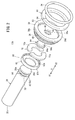
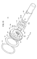
- FIG. 3 is a perspective view of the piston assembly from the piston rod side.
- 4A is a first explanatory view of a piston assembly method
- FIG. 4B is a second explanatory view of the piston assembly method
- FIG. 4C is a third description of the piston assembly method.
- FIG. FIG. 5 is a cross-sectional view of the piston assembly according to the second embodiment.
- FIG. 6 is a perspective view of the piston assembly according to the second embodiment.
- FIG. 7 is a cross-sectional view of the piston assembly according to the third embodiment.
- FIG. 8A is a cross-sectional view of the piston assembly according to the fourth embodiment
- FIG. 8B is a cross-sectional view of the piston assembly according to the fifth embodiment
- FIG. 9A is a cross-sectional view of the piston assembly according to the sixth embodiment
- FIG. 9B is a cross-sectional view of the piston assembly according to the seventh embodiment
- FIG. 10A is a cross-sectional view of the piston assembly according to the eighth embodiment
- FIG. 10B is a cross-sectional view of the piston assembly according to the ninth embodiment
- FIG. 11 is a cross-sectional view of the piston assembly according to the tenth embodiment
- FIG. 12 is a cross-sectional view of the piston assembly according to the eleventh embodiment.
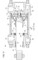
- FIG. 13 is a cross-sectional view of a fluid pressure cylinder including a piston assembly according to a twelfth embodiment.
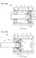
- FIG. 14A is a cross-sectional view of a fluid pressure cylinder configured as a single-acting cylinder
- FIG. 14B is a cross-sectional view of another fluid pressure cylinder configured as a single-acting cylinder.
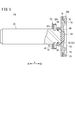
- FIG. 15 is a sectional view of a piston assembly according to a thirteenth embodiment. 16 is a perspective view from the piston rod side of the piston assembly shown in FIG.
- a fluid pressure cylinder 10 ⁇ / b> A shown in FIG. 1 includes a hollow cylindrical cylinder tube 12 (body), a head cover 14 disposed at one end of the cylinder tube 12, and the other end of the cylinder tube 12.
- a rod cover 16 disposed and a piston assembly 17A disposed so as to be reciprocally movable along the axial direction of the cylinder tube 12 are provided.
- the piston assembly 17 ⁇ / b> A includes a piston unit 18 that is arranged in the cylinder tube 12 so as to be movable in the axial direction (arrow X direction), and a piston rod 20 that is connected to the piston unit 18.
- the fluid pressure cylinder 10A is used as an actuator for conveying a workpiece, for example.
- the cylinder tube 12 is made of, for example, a metal material such as an aluminum alloy, and includes a cylinder that extends along the axial direction. In the present embodiment, the cylinder tube 12 is formed in a hollow cylindrical shape.
- the cylinder tube 12 includes a first port 12a provided on one end side in the axial direction (arrow X2 direction side), a second port 12b provided on the other end side in the axial direction (arrow X1 direction side), and a first A sliding hole 13 (cylinder chamber) communicating with the port 12a and the second port 12b is provided.
- the head cover 14 is, for example, a plate-like body made of the same metal material as the cylinder tube 12, and is provided so as to close one end portion (end portion on the arrow X2 direction side) of the cylinder tube 12.
- One end of the cylinder tube 12 is hermetically closed by the head cover 14.
- the rod cover 16 is, for example, a circular ring-shaped member made of the same metal material as the cylinder tube 12, and is provided so as to close the other end (the end on the arrow X1 direction side) of the cylinder tube 12. ing.
- An outer annular groove 24 is formed on the outer periphery of the rod cover 16.
- An outer seal member 26 made of an elastic material that seals between the outer peripheral surface of the rod cover 16 and the inner peripheral surface of the sliding hole 13 is attached to the outer annular groove 24.
- An inner annular groove 28 is formed on the inner periphery of the rod cover 16.
- An inner seal member 30 made of an elastic material that seals between the inner peripheral surface of the rod cover 16 and the outer peripheral surface of the piston rod 20 is attached to the inner annular groove 28.
- the rod cover 16 is locked by a stopper 32 fixed to the inner peripheral portion on the other end side of the cylinder tube 12.
- the piston unit 18 is accommodated in the cylinder tube 12 (sliding hole 13) so as to be slidable in the axial direction, and the first pressure chamber 13a on the first port 12a side and the second port 12b side in the sliding hole 13 are accommodated. It is partitioned off from the second pressure chamber 13b.
- the piston unit 18 is connected to one end 20 a (hereinafter referred to as “base end 20 a”) of the piston rod 20.
- the piston unit 18 includes a piston main body 38 connected to the piston rod 20, and a packing 34 and a magnet 48 attached to the piston main body 38.
- the piston main body 38 is an annular member that protrudes radially outward from the base end portion 20a of the piston rod 20.
- the outer diameter of the piston body 38 is larger than the outer diameter of the piston rod 20.
- a through hole 38 a penetrating in the axial direction is provided at the center of the piston main body 38.
- An annular packing mounting groove 36 and an annular magnet mounting groove 49 are provided in the outer peripheral portion of the piston main body 38 (hereinafter referred to as “piston outer peripheral portion 38 b”) with an interval in the axial direction.
- the piston main body 38 is provided with a piston side engaging portion 40 that engages with a rod side engaging portion 42 described later of the piston rod 20.
- the piston side engaging part 40 has a shape opened to the side.
- the piston-side engaging portion 40 is formed in a semicircular arc shape that protrudes in the axial direction from a disk-like wall portion 38 c surrounding the through hole 38 a and partially surrounds the through hole 38 a.
- an engagement groove 44 is provided in the inner peripheral portion of the piston side engagement portion 40.
- the engagement groove 44 extends in a semicircular arc shape as in the piston-side engagement portion 40.
- An inward protrusion 45 that protrudes inward is provided adjacent to the engagement groove 44.
- the piston side engaging portion 40 (engaging groove 44) is not limited to a semicircular arc shape, and may be formed in a C shape or a U shape.
- the piston body 38 is provided with a lightening portion 46 that surrounds the piston-side engagement portion 40 and has a depth in the axial direction of the piston body 38. 1 and 3, the lightening portion 46 is formed in an annular shape that opens to the rod cover 16 side, and is provided between the piston-side engaging portion 40 and the magnet mounting groove 49. Note that the lightening portion 46 may be configured by a plurality of holes provided at intervals in the circumferential direction. The meat removal part 46 does not need to be provided.
- the peripheral wall 49a that forms the bottom of the magnet mounting groove 49 is provided with a hole 50 extending in the circumferential direction.
- the hole 50 is provided at a position facing the side opening of the piston side engaging portion 40 and penetrates the peripheral wall 49a in the thickness direction.
- the peripheral wall 49 a is provided with a notch 52 that communicates with the hole 50.
- the notch 52 has an arc shape obtained by partially notching the inner periphery of the peripheral wall 49a.
- a surface 38d on the head cover 14 side of the piston main body 38 is provided with a lightening portion 53 that is recessed toward the piston rod 20 side.
- the lightening portion 53 is formed in an annular shape and is provided between the packing mounting groove 36 and the through hole 38a.
- the lightening part 53 may be comprised by the some hole provided at intervals in the circumferential direction. The meat extraction part 53 does not need to be provided.
- the piston body 38 is made of hard resin.
- the resin-made piston main body 38 can be manufactured by injection molding.
- the piston body 38 is not limited to resin, and may be made of a metal material such as carbon steel, stainless steel, or aluminum alloy.
- the packing 34 is an annular seal member (for example, an O-ring) made of an elastic body mounted on the piston outer peripheral portion 38b (packing mounting groove 36).
- the constituent material of the packing 34 include elastic materials such as rubber materials and elastomer materials.
- the packing 34 is in airtight or liquid tight contact with the inner peripheral surface of the sliding hole 13 and the piston outer peripheral portion 38b (packing mounting groove 36) over the entire circumference.
- the seal 34 seals between the outer peripheral surface of the piston unit 18 and the inner peripheral surface of the sliding hole 13, and the first pressure chamber 13a and the second pressure chamber 13b in the sliding hole 13 are partitioned in an airtight or liquid tight manner. ing.
- the magnet 48 is a circular ring-shaped member, and is mounted on the piston outer peripheral portion 38b (magnet mounting groove 49).
- the magnet 48 is configured to be elastically deformable.
- the magnet 48 is a plastic magnet, and has a slit 54 (cut) in a part in the circumferential direction. For this reason, the magnet 48 can be easily mounted by being elastically deformed when mounted in the magnet mounting groove 49.
- a magnetic sensor (not shown) is attached to the outer surface of the cylinder tube 12 at positions corresponding to both stroke ends of the piston unit 18. The operating position of the piston unit 18 is detected by sensing the magnetism generated by the magnet 48 with a magnetic sensor.
- the piston rod 20 is a columnar (columnar) member extending along the axial direction of the sliding hole 13.
- a piston main body 38 is connected to the proximal end portion 20 a of the piston rod 20.
- a rod-side engagement portion 42 that is engaged with the piston-side engagement portion 40 is provided at the proximal end portion 20 a of the piston rod 20.
- the piston-side engaging portion 40 and the rod-side engaging portion 42 have an axial relative displacement between the piston main body 38 and the piston rod 20 by inserting one engaging portion into the other engaging portion from the side. It is engaged to regulate.
- the rod side engaging portion 42 has a T-shape. Specifically, the rod side engaging portion 42 has an annular engaging protrusion 56 inserted into the engaging groove 44.
- the engagement protrusion 56 extends in an annular shape in the circumferential direction.
- An annular groove 58 extending annularly in the circumferential direction is provided on the outer peripheral portion of the piston rod 20 adjacent to the engagement protrusion 56.
- the structure of the piston side engaging portion 40 and the structure of the rod side engaging portion 42 may be replaced with each other. That is, the piston side engaging portion 40 may have a structure having the engaging protrusion 56, and the rod side engaging portion 42 may have a structure having the engaging groove 44.
- the piston side engaging portion 40 and the rod side engaging portion 42 are engaged with each other so as to be relatively rotatable about the axis a1 of the piston main body 38. Therefore, the piston main body 38 and the piston rod 20 are relatively rotatable around the axis a1 of the piston main body 38.
- the piston rod 20 penetrates the rod cover 16.
- a distal end portion 20 b that is an end portion on the opposite side of the proximal end portion 20 a of the piston rod 20 is exposed to the outside of the sliding hole 13.
- Examples of the constituent material of the piston rod 20 include metal materials such as carbon steel, stainless steel, and aluminum alloy, and hard resin.
- the piston assembly 17A includes a damper mechanism 60 that reduces the impact when the stroke end is reached.
- the damper mechanism 60 includes an outer peripheral side damper 62 disposed on the outer peripheral portion of the piston rod 20 and an end portion side damper 64 disposed on the end surface of the piston rod 20.
- the outer peripheral side damper 62 and the end side damper 64 are made of an elastic material (urethane rubber or the like) such as a rubber material or an elastomer material, for example.
- the outer periphery side damper 62 alleviates the impact when reaching the stroke end on the rod cover 16 side.
- the outer periphery side damper 62 is disposed on the rod cover 16 side of the piston body 38 and in the vicinity of the piston body 38.
- the outer periphery side damper 62 is formed in an annular shape and is disposed so as to surround the piston rod 20.
- An annular stopper mounting groove 70 is provided in the vicinity of the piston main body 38 on the outer periphery of the piston rod 20.
- An annular stopper member 72 is mounted in the stopper mounting groove 70.
- the stopper member 72 includes a plurality of stopper elements 72a divided in the circumferential direction. Each stopper element 72a is formed in an arc shape.
- the stopper member 72 has a half structure, and is composed of two half-arc shaped stopper elements 72a.
- the inner peripheral portion of the stopper member 72 (the inner peripheral portion of the stopper element 72 a) is inserted into the stopper mounting groove 70.
- the stopper member 72 is made of a hard material, for example, the same material as the piston rod 20 described above.
- the outer periphery side damper 62 covers the stopper member 72 and is attached to the stopper member 72.
- the outer peripheral damper 62 includes a damper main body 62 a that covers the rod cover 16 side (arrow X1 direction side) of the stopper member 72, and an outer peripheral covering portion 62 b that covers the outer peripheral portion of the stopper member 72.
- An outer peripheral covering portion 62 b is attached to the outer peripheral portion of the stopper member 72.
- the outer periphery side damper 62 is supported by the stopper member 72. Further, since the outer peripheral damper 62 is mounted on the stopper member 72, the stopper member 72 is prevented from being detached from the stopper mounting groove 70.
- the end side damper 64 reduces the impact when the head end of the head cover 14 is reached.
- the end-side damper 64 is held between the piston main body 38 and the piston rod 20 and protrudes from a through hole 38 a provided in the center of the piston main body 38. In FIG. 1, the end side damper 64 protrudes to the head cover 14 side (arrow X2 direction side) from the surface 38d of the piston main body 38 on the head cover 14 side.
- the protruding end surface of the end side damper 64 may be positioned closer to the rod cover 16 than the end surface of the piston main body 38 on the head cover 14 side.
- the piston cover 17A side is disposed on the head cover 14. Protrusions that protrude from the surface are provided.
- the end side damper 64 has a cylindrical shape (or a disk shape). Specifically, an end portion of the end portion side damper 64 on the piston rod 20 side is provided with an annular flange portion 64a that protrudes radially outward. In FIG. 1, the flange portion 64 a is held between a stepped portion 38 e (reduced diameter portion) provided on the inner peripheral portion of the piston main body 38 and the end surface 20 c of the piston rod 20.
- the end side damper 64 is in close contact with the inner peripheral portion of the piston main body 38 and the end surface 20 c of the piston rod 20, so that the space between the piston main body 38 and the piston rod 20 is airtight or liquid tight. It is sealed.
- the end of the end side damper 64 on the side where the flange 64a is provided bulges in the axial direction in a state before assembly (a state before being held between the piston rod 20 and the piston main body 38). It has the bulging part 64b (refer the virtual line of FIG. 1). Thereby, the end side damper 64 elastically presses the end surface 20c of the piston rod 20 in an assembled state (a state held between the piston rod 20 and the piston main body 38). For this reason, rattling between the piston rod 20 and the piston body 38 is suppressed.
- either the outer peripheral side damper 62 or the end side damper 64 may be omitted, or both the outer peripheral side damper 62 and the end side damper 64 may be omitted.
- a piston main body 38, a piston rod 20, and an end side damper 64 are prepared.
- the end side damper 64 is inserted into the through hole 38a of the piston main body 38 from the side where the piston side engaging portion 40 is provided.
- the piston main body 38 and the piston rod 20 are relatively displaced in the axial direction, and the base end portion 20a (piston side engaging portion 40) of the piston rod 20 is replaced with the piston side engaging portion 40 as shown in FIG. 4B. It inserts between piston outer peripheral parts 38b (thickening part 46).
- the notch 52 of the piston main body 38 allows the engagement protrusion 56 of the piston rod 20 to pass, and the hole 50 receives a part of the engagement protrusion 56 in the circumferential direction. That is, a part of the engagement protrusion 56 in the circumferential direction passes through the notch 52 of the piston main body 38 and is inserted into the hole 50.
- the notch 52 and the hole 50 function as escape portions for avoiding the engagement protrusion 56 of the piston rod 20 from interfering with the piston outer peripheral portion 38b.
- the axis a1 of the piston main body 38 and the axis a2 of the piston rod 20 are shifted from each other, and the rod side engaging portion 42 is located on the side of the piston side engaging portion 40. Therefore, as shown in FIG. 4C, the piston main body 38 and the piston rod 20 are moved relative to each other in a direction perpendicular to the axis a1 of the piston main body 38 so that the axis a1 of the piston main body 38 and the axis a2 of the piston rod 20 coincide.
- the engagement protrusion 56 is inserted into the engagement groove 44 by being moved. Thereby, the piston side engaging part 40 and the rod side engaging part 42 will be in an engaged state, and the piston main body 38 and the piston rod 20 will be in the connected state.
- the packing 34 and the magnet 48 are mounted on the piston main body 38, and the stopper member 72 and the outer circumferential damper 62 are mounted on the piston rod 20.
- the packing 34 and the magnet 48 may be attached to the piston main body 38 before the end side damper 64 and the piston rod 20 are attached to the piston main body 38.
- the two stopper elements 72a are individually mounted in the stopper mounting groove 70 of the piston rod 20 so as to form the annular stopper member 72. (Fit).
- the outer circumferential damper 62 is moved from the distal end portion 20b side of the piston rod 20 toward the proximal end portion 20a side, and the outer circumferential damper 62 is placed on the stopper member 72 (two stopper elements 72a). Accordingly, the stopper member 72 is prevented from being detached from the stopper mounting groove 70, and the outer peripheral side damper 62 is held at a predetermined position on the outer peripheral portion of the piston rod 20.
- the piston assembly 17A shown in FIG. 1 is obtained.
- the piston unit 18 including the piston body 38 is supported by the cylinder tube 12, and the piston rod 20 is supported by the rod cover 16.
- the state where the axis a1 of the piston main body 38 and the axis a2 of the piston rod 20 coincide with each other is maintained. Therefore, the engagement between the piston side engaging portion 40 and the rod side engaging portion 42 is maintained.
- the fluid pressure cylinder 10A moves the piston unit 18 in the axial direction in the sliding hole 13 by the action of the pressure fluid (for example, compressed air) introduced through the first port 12a or the second port 12b. Thereby, the piston rod 20 connected to the piston unit 18 moves forward and backward.
- the pressure fluid for example, compressed air
- the second port 12b is opened to the atmosphere, and pressure fluid is supplied from a pressure fluid supply source (not shown) through the first port 12a.
- a pressure fluid supply source not shown
- One pressure chamber 13a is supplied.
- the piston unit 18 is pushed toward the rod cover 16 by the pressure fluid.
- the piston unit 18 is displaced (advanced) together with the piston rod 20 toward the rod cover 16 side.
- the forward movement of the piston unit 18 is stopped when the outer circumferential damper 62 contacts the end face of the rod cover 16.
- the piston body 38 and the rod cover 16 are prevented from coming into direct contact with each other by the outer peripheral damper 62 made of an elastic material. Thereby, it is possible to effectively prevent or suppress the generation of impact and impact sound associated with the piston main body 38 reaching the forward position (stroke end on the rod cover 16 side).
- the first port 12a is opened to the atmosphere, and pressure fluid is supplied from a pressure fluid supply source (not shown) through the second port 12b to the second pressure chamber. 13b. Then, the piston unit 18 is pushed toward the head cover 14 by the pressure fluid. As a result, the piston unit 18 is displaced toward the head cover 14 side.
- the piston main body 38 has the piston side engaging portion 40, and the piston rod 20 is engaged with the piston side engaging portion 40.
- the piston-side engaging portion 40 and the rod-side engaging portion 42 are inserted in the axial direction between the piston main body 38 and the piston rod 20 by inserting one engaging portion into the other engaging portion from the side. Engages so as to regulate relative displacement.
- the piston side engaging portion 40 and the rod side engaging portion 42 are displaced in a direction perpendicular to the axis a1 of the piston main body 38.
- this assembly can be easily performed manually without using a dedicated tool, equipment or device. Therefore, according to the piston assembly 17A of the present invention, the assembly work can be simplified.
- one of the piston-side engagement portion 40 and the rod-side engagement portion 42 has a U-shaped, C-shaped, or semicircular arc-shaped engagement groove 44, and the piston-side engagement
- the other engaging portion of the portion 40 and the rod side engaging portion 42 has an annular engaging protrusion 56 inserted into the engaging groove 44.
- the piston-side engagement portion 40 and the rod-side engagement portion 42 are engaged with each other so as to be relatively rotatable about the axis a1 of the piston body 38.
- the piston rod 20 can be easily rotated when the fluid pressure cylinder 10A is installed in the facility, which is convenient.
- the piston rod 20 can be rotated in the same manner for a piston assembly 17B (FIGS. 5 and 6) including a polygonal piston main body 38A described later.
- the damper mechanism 60 is provided to reduce the impact when the stroke end is reached, and the damper mechanism 60 is supported by the piston body 38 so as not to transmit the impact load to the piston body 38 when the stroke end is reached. Therefore, the piston main body 38 only needs to be designed to have a strength that can withstand the pressure from the working fluid, and can be made of resin. That is, even in the case of the resin piston main body 38, practical durability is easily obtained. By making the piston body 38 of resin, the weight of the piston assembly 17A can be reduced.
- the damper mechanism 60 has an outer periphery side damper 62 disposed on the outer periphery of the piston rod 20, and a stopper mounting groove 70 extending in the circumferential direction is provided on the outer periphery of the piston rod 20. ing.
- the stopper mounting groove 70 is mounted with a stopper member 72 divided into a plurality in the circumferential direction.
- the outer circumferential damper 62 covers the stopper member 72, whereby the outer circumferential damper 62 is supported by the stopper member 72 and the stopper member 72 is prevented from being detached from the stopper mounting groove 70.
- the damper mechanism 60 has an end-side damper 64 disposed on the end surface 20 c of the piston rod 20, and the end-side damper 64 is held between the piston body 38 and the piston rod 20. At the same time, it protrudes from a through hole 38 a provided at the center of the piston body 38. With the end side damper 64 having such a configuration, it is possible to satisfactorily prevent the impact load from being transmitted to the piston body 38 when the other stroke end is reached.
- the end side damper 64 seals between the piston main body 38 and the piston rod 20. Therefore, since the end side damper 64 also serves as a seal member between the piston main body 38 and the piston rod 20, the number of parts can be reduced as compared with a configuration in which the damper and the seal member are provided as separate parts. .
- the end-side damper 64 elastically presses the end surface 20c of the piston rod 20. With this configuration, rattling between the piston body 38 and the piston rod 20 can be prevented.
- the piston main body 38 is provided with a lightening portion 46 that surrounds the piston-side engaging portion 40 and has a depth in the axial direction of the piston main body 38. For this reason, weight reduction of the piston assembly 17A including the piston main body 38 is achieved. Further, by reducing the weight of the piston assembly 17A, the amount of pressure fluid consumed can be reduced, and energy saving can be achieved.
- the present invention can be applied not only to the above-described circular piston body 38 but also to a polygonal piston body 38. Therefore, in the fluid pressure cylinder, instead of the piston assembly 17A having the circular piston body 38, a piston assembly 17B having the polygonal piston body 38A shown in FIGS. 5 and 6 may be employed.
- the piston body 38A of the piston assembly 17B has an octagonal shape.
- the piston body 38A is provided with a plurality of magnet mounting grooves 74 at intervals in the circumferential direction.
- the plurality of magnet mounting grooves 74 are provided on one surface of the piston main body 38A and have a depth in the axial direction of the piston main body 38A.
- a magnet 76 is mounted in one magnet mounting groove 74.
- the magnet 76 is, for example, a ferrite magnet or a rare earth magnet.
- An annular packing mounting groove 78 is provided on the outer peripheral portion of the piston main body 38A.
- the bottom of the packing mounting groove 78 extends in an annular shape in the circumferential direction.
- a packing 79 made of an elastic member is mounted in the packing mounting groove 78.
- the outer peripheral part shape of the packing 79 is formed in the same polygon (an octagon in the case of FIG. 6) as the piston main body 38A.
- the inner peripheral shape of the packing 79 is circular.
- the other part of the piston assembly 17B is configured in the same manner as the piston assembly 17A.
- piston assembly 17B the same effects as the piston assembly 17A can be obtained, for example, it can be easily assembled manually without using a dedicated tool, equipment or device.
- piston rod 20 having a solid structure is employed, but a piston rod 20A having a hollow structure may be employed as in the piston assembly 17C shown in FIG. With this configuration, it is possible to obtain a piston assembly 17C that is further reduced in weight and energy. Note that the opening on one end side of the piston rod 20 ⁇ / b> A is airtightly or liquid tightly closed by the end side damper 64.
- piston rod 20 protruding only on one side of the piston main body 38 is adopted.
- Piston rods 82 and 84 protruding on both sides of the main body 38B may be employed.
- first piston side engaging portion 40A and “second piston side engaging portion 40B”
- first piston side engaging portion 40A and “second piston side engaging portion 40B”
- the piston rod 82 includes a first rod 82A that engages with the first piston-side engaging portion 40A and a second rod 82B that engages with the second piston-side engaging portion 40B.
- the first rod 82A and the second rod 82B are configured similarly to the piston rod 20 described above, and have a solid structure.
- An intermediate member 83 is interposed between the first rod 82A and the second rod 82B.
- the intermediate member 83 may be made of an elastic material similar to that of the outer peripheral side damper 62 described above. Thereby, the intermediate member 83 presses the end surface 82A1 of the first rod 82A and the end surface 82B1 of the second rod 82B, and rattling between the piston main body 38B and the first rod 82A is suppressed, and the piston main body 38B and the first The backlash between the two rods 82B is suppressed.
- the intermediate member 83 is in close contact with the piston main body 38B, the first rod 82A, and the second rod 82B, thereby also serving as an air seal for the first rod 82A side and the second rod 82B side.
- outer peripheral side dampers 62 are disposed on the outer peripheral portions of the first rod 82A and the second rod 82B, respectively, and stoppers mounted on the first rod 82A and the second rod 82B.
- the outer periphery side dampers 62 are supported by the members 72, respectively.
- a piston assembly 17E shown in FIG. 8B is obtained by changing the first rod 82A, the second rod 82B, and the intermediate member 83 in the piston assembly 17D shown in FIG. 8A to a hollow structure. That is, the piston assembly 17E includes a piston main body 38B and hollow piston rods 84 (first rod 84A and second rod 84B) connected to the piston main body 38B, and the first rod 84A and the second rod. A hollow intermediate member 83a is interposed between 84B and 84B.
- both the outer peripheral side damper 62 and the end side damper 64 are provided in the piston assembly 17A (FIG. 1).
- the outer peripheral side damper 62 is used as a damper mechanism. May be provided.
- the piston body 38C of the piston assembly 17F is configured in the same manner as the piston body 38 of the piston assembly 17A, except that a through hole penetrating in the axial direction is not provided.
- only the end side damper 64 may be provided as the damper mechanism (the outer peripheral side damper 62 may be omitted in the piston assembly 17A).
- the damper mechanism may not be provided.
- the magnet 48 may be omitted.
- the magnet mounting groove 49 may be left in the piston main body 38 as in the piston assembly 17H shown in FIG. 10A.
- the piston main body 38D which abbreviate
- piston assembly 17A when the piston main body 38 is made of a low friction material, the piston outer peripheral portion 38b functions as a wear ring.
- a piston body 38E provided with an annular wear ring mounting groove 86 is employed, and a wear ring 88 made of a low friction material is mounted in the wear ring mounting groove 86. May be.
- Wear ring 88 is an annular member for preventing the outer peripheral surface of piston body 38E from contacting the inner peripheral surface of sliding hole 13 (FIG. 1).
- the outer diameter of the wear ring 88 is larger than the outer shape of the piston main body 38E.
- the low friction material include a synthetic resin material having both low friction and wear resistance such as tetrafluoroethylene (PTFE), a metal material (for example, bearing steel), and the like.
- a piston main body 38F to which no magnet and wear ring are attached is adopted, and the damper mechanism may be omitted.
- a fluid pressure cylinder 10B shown in FIG. 13 includes a hollow cylindrical cylinder tube 102 (body), a head cover 104 disposed at one end of the cylinder tube 102, and a rod cover 106 disposed at the other end of the cylinder tube 102.
- the fluid pressure cylinder 10B further includes a piston assembly 17L disposed so as to be reciprocally movable with respect to the cylinder tube 102, a damper mechanism 60A, and a cushion mechanism 110 that alleviates an impact at one and the other stroke ends of the piston unit 18.
- the piston assembly 17L includes a piston unit 18 disposed in the cylinder tube 102 so as to be movable in the axial direction (arrow X direction), and a piston rod 108 coupled to the piston unit 18.
- the cylinder tube 102 is formed of a cylindrical body, and a sliding hole 103 (cylinder chamber) in which the piston unit 18 is accommodated and closed by the head cover 104 and the rod cover 106 is formed.
- the first stepped portion 112 of the head cover 104 is inserted into the end of the cylinder tube 102 on the arrow X2 direction side.
- the head cover 104 is formed with a first central cavity 116 and a first port 118 communicating with the first central cavity 116. Pressure fluid is supplied and discharged through the first port 118.
- the second stepped portion 120 of the rod cover 106 is inserted into the end of the cylinder tube 102 on the arrow X1 direction side.
- the rod cover 106 is formed with a second central cavity portion 124 and a second port 126 communicating with the second central cavity portion 124. Pressure fluid is supplied and discharged through the second port 126.
- a ring-shaped bush 130 and packing 132 are disposed on the inner peripheral portion of the rod cover 106.
- the piston unit 18 is configured similarly to the piston unit 18 of the piston assembly 17A (FIG. 1).
- the damper mechanism 60A includes an outer peripheral damper 62 (same configuration as the outer peripheral damper 62 shown in FIG. 1) disposed on the outer periphery of the piston rod 108, an end damper 64A disposed on the end surface 108a of the piston rod 108, Have The outer peripheral damper 62 is located at the end of the second cushion member 142 on the piston main body 38 side.
- the end side damper 64 ⁇ / b> A is obtained by modifying the end side damper 64 (FIG. 1) into a hollow shape, and is held between the end surface 108 a of the piston rod 108 and the inner peripheral portion of the piston main body 38.
- the cushion mechanism 110 includes a first cushion member 140 and a second cushion member 142 (cushion ring) provided on the movable portion (piston rod 108) side, and an elasticity provided on the fixed portion (head cover 104 and rod cover 106) side. It has the ring-shaped 1st cushion seal 144 and 2nd cushion seal 146 which consist of members.
- the first cushion member 140 is provided coaxially with the piston rod 108 at the end of the piston rod 108 on the arrow X2 direction side. Specifically, the first cushion member 140 is formed with a smaller diameter than the piston rod 108, and protrudes in the direction of the arrow X2 from the end surface 108a of the piston rod 108 and the end surface of the end-side damper 64A.
- the first cushion member 140 is formed in a hollow or solid cylindrical shape. The outer diameter of the first cushion member 140 is smaller than the outer diameter of the end side damper 64A.
- the first cushion member 140 may be a part formed integrally with the piston rod 108 or may be a separate part joined to the piston rod 108. When the first cushion member 140 is a separate component from the piston rod 108, the first cushion member 140 can be joined to the piston rod 108 by joining means such as welding, adhesion, and screwing.
- the first cushion seal 144 is held on the inner periphery of the ring-shaped first holder 148.
- the first holder 148 is fixed to the inner peripheral portion of the first stepped portion 112 of the head cover 104.
- the sliding hole 103 and the first central cavity 116 communicate with each other via the hole 148a.
- the first cushion seal 144 is in sliding contact with the outer peripheral surface of the first cushion member 140 over the entire circumference.
- the second cushion member 142 is adjacent to the rod cover 106 side (arrow X1 direction side) of the piston unit 18 and is provided coaxially with the piston rod 108 in the vicinity of the piston unit 18.
- the second cushion member 142 is a ring-shaped member having a larger diameter than the piston rod 108 and a smaller diameter than the piston unit 18, and is joined to the outer peripheral surface of the piston rod 108 by, for example, welding or adhesion. Yes.
- the outer diameter of the second cushion member 142 is slightly larger than the outer diameter of the piston rod 108.
- the second cushion seal 146 is held on the inner periphery of the ring-shaped second holder 150.
- the second holder 150 is fixed to the inner peripheral portion of the second stepped portion 120 of the rod cover 106.
- the sliding hole 103 and the second central cavity 124 communicate with each other through the hole 150a.
- the second cushion seal 146 is in sliding contact with the outer peripheral surface of the second cushion member 142 over the entire circumference.
- the fluid pressure cylinder 10 ⁇ / b> B moves the piston unit 18 in the axial direction in the sliding hole 103 by the action of the pressure fluid introduced through the first port 118 or the second port 126. Thereby, the piston rod 108 connected to the piston unit 18 moves forward and backward.
- the second port 126 is opened to the atmosphere, and the first port 118 and the first central cavity 116 116 from a pressure fluid supply source (not shown).
- air is supplied to the first pressure chamber 103a through the hole 148a.
- the piston unit 18 is displaced (advanced) together with the piston rod 108 toward the rod cover 106 side.
- the air in the second pressure chamber 103 b is discharged from the second port 126 through the hole 150 a of the second holder 150 and the second central cavity 124.
- the outer peripheral damper 62 may be formed in the magnitude
- the second cushion member 142 When the piston unit 18 approaches the forward position, the second cushion member 142 is inserted into the hole 150a of the second holder 150. Accordingly, the inner peripheral portion of the second cushion seal 146 contacts the outer peripheral surface of the second cushion member 142, and an airtight seal is formed at this contact portion.
- an air cushion is formed in the second pressure chamber 103b.
- the air cushion in the second pressure chamber 103b serves as a displacement resistance when the piston unit 18 is displaced toward the rod cover 106, thereby decelerating the displacement of the piston unit 18 near the stroke end on the rod cover 106 side. Therefore, the impact when the piston unit 18 reaches the stroke end is further alleviated.
- the air is exhausted little by little to the second port 126 through a small hole (not shown).
- the first port 118 is opened to the atmosphere, and the second port 126 and the second center are connected from a pressure fluid supply source (not shown). Air is supplied to the second pressure chamber 103b through the cavity 124 and the hole 150a. As a result, the piston unit 18 is displaced (retracted) toward the head cover 104 side. In this case, the air in the first pressure chamber 103 a is discharged from the first port 118 through the hole 148 a of the first holder 148 and the first central cavity 116. Then, when the end side damper 64A comes into contact with the first holder 148, the backward movement of the piston unit 18 is stopped.
- the first cushion member 140 When the piston unit 18 approaches the retracted position, the first cushion member 140 is inserted into the hole 148a of the first holder 148. Accordingly, the inner peripheral portion of the first cushion seal 144 comes into contact with the outer peripheral surface of the first cushion member 140, and an airtight seal is formed at this contact portion.
- the air cushion in the first pressure chamber 103a serves as a displacement resistance when the piston unit 18 is displaced toward the head cover 104, thereby decelerating the displacement of the piston unit 18 near the stroke end on the head cover 104 side. Therefore, the impact when the piston unit 18 reaches the stroke end is further alleviated.
- the fluid pressure cylinder 10C shown in FIG. 14A is configured as a so-called single acting cylinder. Specifically, the fluid pressure cylinder 10 ⁇ / b> C is obtained by arranging a spring 154 between the piston unit 18 and the rod cover 16 in the fluid pressure cylinder 10 ⁇ / b> A (FIG. 1). In this case, the second port 12b is open to the atmosphere.
- the piston unit 18 In the fluid pressure cylinder 10C, when pressure fluid is supplied to the first pressure chamber 13a via the first port 12a, the piston unit 18 is displaced (advanced) toward the rod cover 16 by the pressure fluid, and the stroke end of the advance position is reached. And reach.
- the piston unit 18 When the supply of pressurized fluid to the first port 12a is stopped and the first port 12a is opened to the atmosphere, the piston unit 18 is displaced (retracted) toward the head cover 14 by the elastic biasing force of the spring 154, and the retracted position. To reach the stroke end.
- the fluid pressure cylinder 10D shown in FIG. 14B is also configured as a so-called single acting cylinder. Specifically, the fluid pressure cylinder 10 ⁇ / b> D is obtained by arranging a spring 154 between the piston unit 18 and the head cover 14 in the fluid pressure cylinder 10 ⁇ / b> A (FIG. 1). In this case, the first port 12a is open to the atmosphere.
- the piston unit 18 In the fluid pressure cylinder 10D, when the pressure fluid is supplied to the second pressure chamber 13b via the second port 12b, the piston unit 18 is displaced (retracted) toward the head cover 14 by the pressure fluid, and the stroke end of the retracted position is reached. To reach. When the supply of the pressure fluid to the second port 12b is stopped and the second port 12b is opened to the atmosphere, the piston unit 18 is displaced (advanced) to the rod cover 16 side by the elastic biasing force of the spring 154, and advances. The stroke end of the position is reached.
- a piston assembly 17M shown in FIGS. 15 and 16 may be employed.
- the piston assembly 17M includes a piston unit 18a and a piston rod 160 connected to the piston unit 18a.
- the piston unit 18 a includes a piston main body 162 connected to the piston rod 160, and a packing 34 and a magnet 48 attached to the outer periphery of the piston main body 162.
- the constituent material of the piston main body 162 can be selected from the materials exemplified as the constituent material of the piston main body 38 (FIG. 1 and the like) described above.
- An end side damper 64 is disposed between the piston main body 162 and the piston rod 160. The end side damper 64 is attached to a through hole 162 a provided in the piston main body 162.
- the piston main body 162 is provided with a piston-side engaging portion 166 by integral molding.
- the piston side engaging portion 166 has a shape opened to the side.
- the piston-side engaging portion 166 bulges in the axial direction (arrow X direction) from the end surface 162 b of the piston main body 162 and is configured in a U shape when viewed from the axial direction.
- a U-shaped engagement groove 166 a is provided on the inner peripheral surface of the piston-side engagement portion 166.
- the piston-side engaging portion 166 includes a curved portion 167 extending in an arc shape along the outer peripheral shape of the through hole 162a, and two arm portions 168 extending linearly and parallel to each other from both ends of the curved portion 167. And have. When viewed from the axial direction of the piston main body 162, the distal ends of the two arm portions 168 are located radially outside of the through hole 162a.
- the piston main body 162 is provided with the piston-side engaging portion 166 configured in a U-shape.
- the piston side engaging part 166 functions as a reinforcing rib, and the piston main body 162 is reinforced.
- operation of the fluid pressure cylinder in which the piston assembly 17M was integrated can be improved.
- a rod side engaging portion 42 engaged with the U-shaped engaging groove 166a of the piston side engaging portion 166 is provided.
- the rod side engaging portion 42 is configured by an annular engaging protrusion 56.
- An annular groove 58 is formed adjacent to the engagement protrusion 56.
- a ring-shaped outer peripheral damper 170 made of an elastic material that relieves an impact when reaching the stroke end in the direction of the arrow X1 is disposed.
- a ring-shaped spacer 172 is interposed between the piston main body 162 and the outer peripheral side damper 170. The spacer 172 is in contact with the piston side engaging portion 166.
- the piston main body 162, the spacer 172, and the outer peripheral side damper 170 are laminated in the axial direction.
- the spacer 172 is made of a material harder than the outer peripheral damper 170.
- the constituent material of the spacer 172 may be selected from the materials listed as the constituent material of the piston rod 20 (FIG. 1 and the like) described above.
- the load when reaching the stroke end in the direction of the arrow X1 is transmitted to the piston main body 162 via the outer peripheral damper 170. Accordingly, the piston body 162 receives a load when the stroke end is reached.
- the piston main body 162 is made of a metal material, the strength of the piston main body 162 can be sufficiently secured because the strength is higher than that of the resin material.
- a ring-shaped spacer 172 that is harder than the outer peripheral damper 170 is interposed between the piston main body 162 and the outer peripheral damper 170, so that the outer peripheral damper 170 has a U-shaped piston side.
- the entire periphery is supported not by the engaging portion 166 but by the ring-shaped spacer 172. Therefore, it is possible to prevent the outer peripheral damper 170 made of an elastic material from being damaged by a load when reaching the stroke end.
- the present invention is not limited to the above-described embodiment, and various modifications can be made without departing from the gist of the present invention.
- the present invention can also be applied to a hydraulic cylinder whose piston unit and cylinder tube have non-circular cross-sectional shapes (such as a square shape or an elliptical shape such as an elliptical shape) (the piston assembly 17B in FIG. One example).
- the present invention can also be applied to a multi-rod type (dual rod type or the like) fluid pressure cylinder having a plurality of pistons and piston rods.
- the present invention is not limited to a fluid pressure cylinder used as an actuator or the like, but can be applied to other forms of fluid pressure devices having a piston.
- Other forms of fluid pressure devices having a piston to which the present invention can be applied include, for example, a valve device that switches a flow path by moving a valve body by a piston, and a piston that is connected to the piston rod as an input shaft.
- a measuring cylinder that measures the length by displacing it, a slide table that displaces the table that is connected to the piston via the piston rod by displacing the piston, and a grip that opens and closes by displacing the piston and converting this piston displacement
- a chuck device for gripping a workpiece by the portion.
Landscapes
- Engineering & Computer Science (AREA)
- Physics & Mathematics (AREA)
- Fluid Mechanics (AREA)
- Mechanical Engineering (AREA)
- General Engineering & Computer Science (AREA)
- Actuator (AREA)
Abstract
Priority Applications (7)
| Application Number | Priority Date | Filing Date | Title |
|---|---|---|---|
| US16/466,522 US11067173B2 (en) | 2016-12-06 | 2017-11-13 | Piston assembly and fluid pressure device |
| RU2019120892A RU2737877C1 (ru) | 2016-12-06 | 2017-11-13 | Поршневой узел и гидро(пневмо)устройство |
| CN201780075451.3A CN110073114B (zh) | 2016-12-06 | 2017-11-13 | 活塞组装体以及流体压力装置 |
| EP17878719.8A EP3553326A4 (fr) | 2016-12-06 | 2017-11-13 | Ensemble piston et dispositif à pression de fluide |
| BR112019011573A BR112019011573A2 (pt) | 2016-12-06 | 2017-11-13 | conjunto de pistão e dispositivo de pressão de fluído |
| KR1020197019427A KR102201138B1 (ko) | 2016-12-06 | 2017-11-13 | 피스톤 조립체 및 유체압 장치 |
| MX2019006441A MX2019006441A (es) | 2016-12-06 | 2017-11-13 | Montaje de piston y dispositivo de presion de fluido. |
Applications Claiming Priority (4)
| Application Number | Priority Date | Filing Date | Title |
|---|---|---|---|
| JP2016236402 | 2016-12-06 | ||
| JP2016-236402 | 2016-12-06 | ||
| JP2017-025576 | 2017-02-15 | ||
| JP2017025576A JP6598083B2 (ja) | 2016-12-06 | 2017-02-15 | ピストン組立体及び流体圧装置 |
Publications (1)
| Publication Number | Publication Date |
|---|---|
| WO2018105314A1 true WO2018105314A1 (fr) | 2018-06-14 |
Family
ID=62491179
Family Applications (1)
| Application Number | Title | Priority Date | Filing Date |
|---|---|---|---|
| PCT/JP2017/040679 WO2018105314A1 (fr) | 2016-12-06 | 2017-11-13 | Ensemble piston et dispositif à pression de fluide |
Country Status (1)
| Country | Link |
|---|---|
| WO (1) | WO2018105314A1 (fr) |
Citations (4)
| Publication number | Priority date | Publication date | Assignee | Title |
|---|---|---|---|---|
| JPS5147994Y2 (fr) * | 1972-04-11 | 1976-11-18 | ||
| JPH0343139U (fr) * | 1989-09-01 | 1991-04-23 | ||
| JPH05346106A (ja) * | 1992-06-10 | 1993-12-27 | Aisan Ind Co Ltd | シリンダ装置 |
| JP2014114874A (ja) | 2012-12-10 | 2014-06-26 | Smc Corp | 流体圧シリンダ |
-
2017
- 2017-11-13 WO PCT/JP2017/040679 patent/WO2018105314A1/fr unknown
Patent Citations (4)
| Publication number | Priority date | Publication date | Assignee | Title |
|---|---|---|---|---|
| JPS5147994Y2 (fr) * | 1972-04-11 | 1976-11-18 | ||
| JPH0343139U (fr) * | 1989-09-01 | 1991-04-23 | ||
| JPH05346106A (ja) * | 1992-06-10 | 1993-12-27 | Aisan Ind Co Ltd | シリンダ装置 |
| JP2014114874A (ja) | 2012-12-10 | 2014-06-26 | Smc Corp | 流体圧シリンダ |
Similar Documents
| Publication | Publication Date | Title |
|---|---|---|
| US10851813B2 (en) | Method for producing piston assembly and hydraulic fluid device | |
| CN109563855B (zh) | 流体压力装置 | |
| JP6598079B2 (ja) | ロッド組立体及び流体圧装置 | |
| KR102175357B1 (ko) | 유체압 장치 및 피스톤 조립체의 제조 방법 | |
| US11371538B2 (en) | Fluid pressure cylinder | |
| JP6598083B2 (ja) | ピストン組立体及び流体圧装置 | |
| WO2018105314A1 (fr) | Ensemble piston et dispositif à pression de fluide |
Legal Events
| Date | Code | Title | Description |
|---|---|---|---|
| 121 | Ep: the epo has been informed by wipo that ep was designated in this application |
Ref document number: 17878719 Country of ref document: EP Kind code of ref document: A1 |
|
| NENP | Non-entry into the national phase |
Ref country code: DE |
|
| REG | Reference to national code |
Ref country code: BR Ref legal event code: B01A Ref document number: 112019011573 Country of ref document: BR |
|
| ENP | Entry into the national phase |
Ref document number: 20197019427 Country of ref document: KR Kind code of ref document: A |
|
| ENP | Entry into the national phase |
Ref document number: 2017878719 Country of ref document: EP Effective date: 20190708 |
|
| ENP | Entry into the national phase |
Ref document number: 112019011573 Country of ref document: BR Kind code of ref document: A2 Effective date: 20190604 |