WO2018029985A1 - 可変容量型過給機 - Google Patents
可変容量型過給機 Download PDFInfo
- Publication number
- WO2018029985A1 WO2018029985A1 PCT/JP2017/022300 JP2017022300W WO2018029985A1 WO 2018029985 A1 WO2018029985 A1 WO 2018029985A1 JP 2017022300 W JP2017022300 W JP 2017022300W WO 2018029985 A1 WO2018029985 A1 WO 2018029985A1
- Authority
- WO
- WIPO (PCT)
- Prior art keywords
- contact member
- housing
- variable displacement
- contact
- holding portion
- Prior art date
- Legal status (The legal status is an assumption and is not a legal conclusion. Google has not performed a legal analysis and makes no representation as to the accuracy of the status listed.)
- Ceased
Links
Images



Classifications
-
- F—MECHANICAL ENGINEERING; LIGHTING; HEATING; WEAPONS; BLASTING
- F01—MACHINES OR ENGINES IN GENERAL; ENGINE PLANTS IN GENERAL; STEAM ENGINES
- F01D—NON-POSITIVE DISPLACEMENT MACHINES OR ENGINES, e.g. STEAM TURBINES
- F01D17/00—Regulating or controlling by varying flow
- F01D17/10—Final actuators
- F01D17/12—Final actuators arranged in stator parts
- F01D17/14—Final actuators arranged in stator parts varying effective cross-sectional area of nozzles or guide conduits
- F01D17/16—Final actuators arranged in stator parts varying effective cross-sectional area of nozzles or guide conduits by means of nozzle vanes
-
- F—MECHANICAL ENGINEERING; LIGHTING; HEATING; WEAPONS; BLASTING
- F02—COMBUSTION ENGINES; HOT-GAS OR COMBUSTION-PRODUCT ENGINE PLANTS
- F02B—INTERNAL-COMBUSTION PISTON ENGINES; COMBUSTION ENGINES IN GENERAL
- F02B37/00—Engines characterised by provision of pumps driven at least for part of the time by exhaust
- F02B37/12—Control of the pumps
- F02B37/24—Control of the pumps by using pumps or turbines with adjustable guide vanes
-
- Y—GENERAL TAGGING OF NEW TECHNOLOGICAL DEVELOPMENTS; GENERAL TAGGING OF CROSS-SECTIONAL TECHNOLOGIES SPANNING OVER SEVERAL SECTIONS OF THE IPC; TECHNICAL SUBJECTS COVERED BY FORMER USPC CROSS-REFERENCE ART COLLECTIONS [XRACs] AND DIGESTS
- Y02—TECHNOLOGIES OR APPLICATIONS FOR MITIGATION OR ADAPTATION AGAINST CLIMATE CHANGE
- Y02T—CLIMATE CHANGE MITIGATION TECHNOLOGIES RELATED TO TRANSPORTATION
- Y02T10/00—Road transport of goods or passengers
- Y02T10/10—Internal combustion engine [ICE] based vehicles
- Y02T10/12—Improving ICE efficiencies
Definitions
- the present disclosure relates to a variable displacement supercharger including an actuating member that operates in response to the power of an actuator.
- variable displacement turbochargers have become widespread.
- a plurality of nozzle vanes are annularly arranged in a flow path for guiding the exhaust gas from the turbine scroll flow path to the turbine impeller.
- the nozzle vanes are attached to the blade shaft.
- the flow passage width (so-called nozzle throat width) is changed to control the flow rate of the exhaust gas flowing through the flow passage.
- an arm is attached to a drive shaft.
- the drive shaft is one of connection members connecting the actuator and the blade shaft.
- the tip of the arm is located between two stops provided on the turbine housing.
- the two stoppers restrict the operation of the arm.
- the angles of the nozzle vanes are regulated.
- the two stoppers are constituted by bolts. An axial position adjustment of each of the two stops with respect to the turbine housing is possible.
- an object of the present disclosure is to provide a variable displacement supercharger capable of facilitating the opening adjustment at the time of installation.
- a variable displacement supercharger includes a variable displacement mechanism having a nozzle vane, an actuator for driving the nozzle vane, and an actuating member operated by receiving the power of the actuator.
- the actuating member, and the holding portion provided on one of the housings, the abutting member held on the holding portion, the actuating member and the other of the housing provided on the other of the actuating member And two abutted parts opposed from both sides of the direction.
- the contact member may be a bolt, and the holder may have a screw hole into which the bolt is screwed.
- One or both of the one end surface of the contact member and the contact surface of the abutted part in contact with the contact member may be a curved surface.
- the retaining portion may be located between the turbine housing and the compressor housing.
- the opening adjustment at the time of installation can be facilitated.
- FIG. 1 is a schematic cross-sectional view of a variable displacement turbocharger.
- FIG. 2A is an extracted view of the upper broken line portion of FIG.
- FIG.2 (b) is an extraction figure of the dashed-dotted line part of the lower side of FIG. It is a top view of a support ring and a guide ring. It is a figure which shows the state by which the drive ring was supported by the guide ring. It is an external appearance perspective view of a variable displacement turbocharger. It is the elements on larger scale near the holding part.
- FIG. 7A is a first diagram for explaining the operation of the actuating member.
- FIG. 7 (b) is a second view for explaining the operation of the actuating member.
- FIG. 7A is a first diagram for explaining the operation of the actuating member.
- FIG. 7 (b) is a second view for explaining the operation of the actuating member.
- FIG. 7C is a third diagram for explaining the operation of the actuating member.
- FIG. 8A is a first view for explaining position adjustment of the contact member.
- FIG. 8B is a second diagram for explaining the position adjustment of the contact member.
- FIG. 8C is a third diagram for explaining position adjustment of the contact member.
- FIG. 8D is a fourth diagram for describing position adjustment of the contact member. It is an explanatory view for explaining the 1st modification. It is an explanatory view for explaining the 2nd modification.
- FIG. 1 is a schematic cross-sectional view of a variable displacement turbocharger C.
- the variable displacement turbocharger C includes a turbocharger body 1.
- the turbocharger body 1 includes a bearing housing 2 (housing).
- the turbine housing 4 (housing) is connected to the left side of the bearing housing 2 by a fastening bolt 3.
- the compressor housing 6 (housing) is connected to the right side of the bearing housing 2 by a fastening bolt 5.
- the bearing housing 2, the turbine housing 4 and the compressor housing 6 are integrated.
- the bearing housing 2 is formed with a housing hole 2 a.
- the accommodation hole 2 a penetrates in the left-right direction of the variable displacement turbocharger C.
- the radial bearing 7 (in the present embodiment, as an example, a semi-floating bearing is shown in FIG. 1) is housed in the housing hole 2a.
- the shaft 8 is rotatably supported by the radial bearing 7.
- a turbine impeller 9 is provided at the left end of the shaft 8.
- a turbine impeller 9 is rotatably accommodated in the turbine housing 4.
- a compressor impeller 10 is provided at the right end of the shaft 8.
- a compressor impeller 10 is rotatably accommodated in the compressor housing 6.
- An intake port 11 is formed in the compressor housing 6.
- the intake port 11 opens on the right side of the variable displacement turbocharger C.
- the intake port 11 is connected to an air cleaner (not shown).
- the diffuser flow path 12 is formed.
- the diffuser channel 12 is formed by the facing surfaces of the bearing housing 2 and the compressor housing 6.
- the diffuser passage 12 pressurizes air.
- the diffuser flow passage 12 is annularly formed from the radially inner side to the outer side of the shaft 8.
- the diffuser flow passage 12 communicates with the air intake port 11 via the compressor impeller 10 at the radially inner side of the shaft 8.
- a compressor scroll channel 13 is provided in the compressor housing 6.
- the compressor scroll passage 13 is annular.
- the compressor scroll passage 13 is located, for example, radially outside the shaft 8 with respect to the diffuser passage 12.
- the compressor scroll passage 13 communicates with an intake port of an engine (not shown).
- the compressor scroll passage 13 is also in communication with the diffuser passage 12. Therefore, when the compressor impeller 10 rotates, air is sucked into the compressor housing 6 from the intake port 11.
- the intake air is boosted and pressurized in the process of flowing between the blades of the compressor impeller 10.
- the boosted and boosted air is pressurized (pressure recovery) in the diffuser passage 12 and the compressor scroll passage 13.
- the boosted air is led to the engine.
- a gap 14 is formed between the facing surfaces of the bearing housing 2 and the turbine housing 4.
- the gap 14 is a portion where the flow path x is configured.
- nozzle vanes 62 described later are disposed. Exhaust gas flows through the flow path x.
- the gap 14 is annularly formed from the radially inner side to the outer side of the shaft 8 (turbine impeller 9).
- an exhaust port 16 is formed in the turbine housing 4.
- the exhaust port 16 communicates with the turbine scroll passage 15 via the turbine impeller 9.
- the exhaust port 16 faces the front of the turbine impeller 9.
- the exhaust port 16 is connected to an exhaust gas purification device (not shown).
- the turbine scroll passage 15 communicates with a gas inlet (not shown). Exhaust gas exhausted from the engine is introduced to the gas inlet.
- the turbine scroll flow passage 15 is also in communication with the flow passage x described above. Therefore, the exhaust gas led from the gas inlet to the turbine scroll channel 15 is led to the exhaust port 16 via the channel x and the turbine impeller 9. That is, the flow path x is a flow path from the turbine scroll flow path 15 toward the turbine impeller 9.
- the turbine impeller 9 rotates in the circulation process of the exhaust gas. The rotational force of the turbine impeller 9 is transmitted to the compressor impeller 10 via the shaft 8. The air is pressurized by the rotational force of the compressor impeller 10 and guided to the intake port of the engine.
- variable displacement supercharger C is provided with a variable displacement mechanism 20.
- the variable displacement mechanism 20 changes the flow passage width (a nozzle throat width described later) of the flow passage x of the turbine housing 4.
- the variable displacement mechanism 20 changes the flow velocity of the exhaust gas led to the turbine impeller 9 according to the flow rate of the exhaust gas. Specifically, the variable displacement mechanism 20 reduces the nozzle opening degree of the flow path x when the number of revolutions of the engine is low and the flow rate of the exhaust gas is small. The flow velocity of the exhaust gas led to the turbine impeller 9 is improved.
- the variable displacement mechanism 20 enables the turbine impeller 9 to be rotated even at a low flow rate.
- the configuration of the variable capacity mechanism 20 will be described below.
- the variable displacement mechanism 20 includes a shroud ring 21 and a nozzle ring 22.
- the shroud ring 21 is provided on the turbine housing 4 side.
- the nozzle ring 22 is provided on the bearing housing 2 side so as to face the shroud ring 21.
- the flow path x is defined by the shroud ring 21 and the nozzle ring 22.
- the shroud ring 21 has a main body 21 a.
- the main body portion 21 a is in the form of a thin plate ring.
- a protrusion 21 b is formed on the inner peripheral edge of the main body 21 a.
- the protrusion 21 b protrudes toward the exhaust port 16.
- the nozzle ring 22 includes a main body 22a.
- the main body portion 22a is in the form of a thin plate ring.
- the main body 22 a has the same diameter as the main body 21 a of the shroud ring 21.
- the main body 22a is disposed opposite to the shroud ring 21 with a predetermined distance maintained.
- FIG. 2A is an extracted view of the upper broken line portion of FIG. FIG.2 (b) is an extraction figure of the dashed-dotted line part of the lower side of FIG.
- the main shaft portion 21a of the shroud ring 21 is provided with a pin shaft hole 23a.
- the pin shaft hole 23a penetrates the main body portion 21a in the thickness direction (the axial direction of the shaft 8).
- a plurality (three in the present embodiment, only one in FIG. 2B) is formed at equal intervals in the circumferential direction at the pin axial holes 23a.
- a pin shaft hole 25 a is formed in the main body portion 22 a of the nozzle ring 22.
- the pin shaft hole 25a penetrates the main body 22a in the thickness direction (the axial direction of the shaft 8).
- a plurality of main body portions 22a are formed at equal intervals in the circumferential direction.
- the pin shaft hole 23 a formed in the shroud ring 21 and the pin shaft hole 25 a formed in the nozzle ring 22 face each other.
- the connection pin 24 is inserted into the pin shaft holes 23a and 25a.
- connection pin 24 is inserted into the pin shaft hole 25 a of the nozzle ring 22.
- the other end of the connection pin 24 is inserted into the pin shaft hole 23 a of the shroud ring 21.
- a plurality of (three in the present embodiment, only one in FIG. 2B) connection pins 24 are disposed at equal intervals in the circumferential direction. The facing distance between the shroud ring 21 and the nozzle ring 22 is maintained constant by the connecting pin 24.
- connection pin 24 inserted into the pin shaft hole 25 a of the nozzle ring 22 protrudes to the right of the nozzle ring 22.
- the protruding portion of the connecting pin 24 is crimped.
- the support ring 30 and the guide ring 40 are attached to the right side of the nozzle ring 22.
- the support ring 30 is formed of a cylindrical member.
- the support ring 30 has a cross-sectional shape in which a plate-like member is bent (see FIG. 1).
- FIG. 3 is a plan view of the support ring 30 and the guide ring 40.
- the support ring 30 is provided with the flange part 31, the cylinder part 32, and the bottom face part 33 (it shows by cross hatching in FIG. 3), as shown to FIG. 2 (a), FIG.2 (b).
- the flange portion 31 is annular.
- the cylindrical portion 32 stands on the left side (the far side in FIG. 3) from the inner peripheral edge of the flange portion 31.
- the bottom portion 33 is annular.
- the bottom surface portion 33 is bent radially inward from the left end portion of the cylindrical portion 32.
- the flange part 31 is clamped by the opposing surface of the bearing housing 2 and the turbine housing 4.
- the support ring 30 is held in the turbine housing 4 by fastening the bearing housing 2 and the turbine housing 4 with the fastening bolt 3.
- the guide ring 40 has an annular body 41.
- the inner diameter of the main body portion 41 of the guide ring 40 is approximately equal to the inner diameter of the bottom portion 33 of the support ring 30.
- the main body portion 41 is disposed radially inward of the cylindrical portion 32 in a state of being in contact with the bottom surface portion 33. In FIG. 3, a part of the bottom surface 33 of the support ring 30 on the radially inner side is hidden by the main body 41 of the guide ring 40.
- Support holes 33 a are provided in three places at equal intervals in the circumferential direction on the bottom surface portion 33 of the support ring 30.
- One end of the connection pin 24 is inserted into the support hole 33a.
- three guide holes 41 a are provided in the main body portion 41 of the guide ring 40.
- the guide hole 41a is provided at a position facing the support hole 33a.
- One end of the connection pin 24 is inserted into the support hole 33a.
- the connection pin 24 is inserted into the support hole 33a and the guide hole 41a and crimped.
- a support piece 42 is provided on the main body portion 41 of the guide ring 40.
- a plurality of support pieces 42 (10 in the present embodiment) are provided so as to be separated in the circumferential direction.
- the support piece 42 is composed of a support portion 42a and a drop prevention portion 42b.
- the support portion 42 a bends to the right (the front side in FIG. 3) from the main body portion 41.
- the detachment prevention portion 42b is bent radially outward from the support portion 42a.
- the drop prevention portion 42b faces the main body portion 41 with a predetermined distance therebetween.
- FIG. 4 is a view showing the drive ring 50 supported by the guide ring 40. As shown in FIG. In FIG. 4, the bottom portion 33 of the support ring 30 is shown by cross hatching to facilitate understanding. The drive ring 50 is shown by cross hatching that is coarser than the bottom portion 33.
- the drive ring 50 is constituted by an annular thin plate member.
- the support portion 42 a of the support piece 42 is located radially inward of the drive ring 50.
- the drive ring 50 is rotatably supported between the detachment preventing portion 42 b and the bottom surface portion 33.
- the drive ring 50 is provided with a first engagement portion 51.
- the first engagement portion 51 is cut out radially outward from an end portion on the inner peripheral side of the drive ring 50.
- One end of the transmission link 60 is engaged with the first engagement portion 51.
- one second engagement portion 52 is formed at the end portion on the inner peripheral side of the drive ring 50.
- the second engagement portion 52 has the same shape as the first engagement portion 51.
- One end of the link plate 61 is engaged with the second engagement portion 52.
- the link plate 61 has the same shape as the transmission link 60.
- Insertion holes 60 a and 61 a are formed on the other end side of the transmission link 60 and the other end side of the link plate 61. And as shown to Fig.2 (a), the blade shaft 62a of the nozzle vane 62 is penetrated and attached to the insertion hole 60a. As shown in FIG. 2 (b), one end portion 63 a of the drive shaft 63 is attached to the insertion hole 61 a of the link plate 61.
- the blade shaft 62a is inserted into the blade shaft holes 23b and 25b and rotatably supported.
- the blade shaft hole 23 b is provided radially inward of the pin shaft hole 23 a in the main body portion 21 a of the shroud ring 21.
- the wing shaft hole 23b penetrates the main body portion 21a in the thickness direction (the axial direction of the shaft 8).
- a plurality of wing shaft holes 23b are formed at intervals in the circumferential direction of the main body portion 21a (in the present embodiment, eleven are shown at an equal interval as an example, and only one is shown in FIG. 2A).
- the blade axial holes 23 b formed in the shroud ring 21 opposite to the nozzle ring 22 with respect to the nozzle vanes 62 may be omitted.
- the blade shaft 62a is inserted only into a blade shaft hole 25b formed in the nozzle ring 22 described later and is rotatably supported by a shaft (single shaft holding).
- the blade shaft hole 25 b is provided radially inward of the pin shaft hole 25 a in the main body 22 a of the nozzle ring 22.
- the wing shaft hole 25b penetrates the main body 22a in the thickness direction (the axial direction of the shaft 8).
- a plurality of wing shaft holes 25b are formed at intervals in the circumferential direction of the main body 22a (in the present embodiment, eleven are shown at an equal interval as an example, and only one is shown in FIG. 2A).
- a blade shaft hole 23 b formed in the shroud ring 21 and a blade shaft hole 25 b formed in the nozzle ring 22 face each other.
- One end of the wing shaft 62 a is inserted into the insertion hole 60 a of the transmission link 60.
- the projecting portion of the wing shaft 62a is crimped.
- the transmission link 60 is attached to the wing shaft 62a.
- the blade shafts 62 a and the nozzle vanes 62 are annularly arranged in the flow passage x at intervals in the rotational direction of the turbine impeller 9.
- the drive shaft 63 extends to the right of the drive ring 50, as shown in FIG. 2 (b).
- the extended portion of the drive shaft 63 is inserted into the bearing 64.
- the bearing 64 has an annular main body 64a.
- the main body 64a is attached to the attachment hole 2b.
- the mounting hole 2 b is provided in the bearing housing 2.
- the inner peripheral surface of the bearing hole 64b of the main body portion 64a is a bearing surface.
- the drive shaft 63 is pivotally supported by the bearing hole 64b.
- the rotational direction of the turbine impeller 9 is substantially the same as the circumferential direction of the main body 21 a of the shroud ring 21 or the circumferential direction of the main body 22 a of the nozzle ring 22.
- the drive lever 65 is integrally connected to the other end 63 b side.
- the bearing 64 is disposed between the link plate 61 and the drive lever 65.
- an actuator 66 is provided outside the bearing housing 2, the turbine housing 4, and the compressor housing 6 (see FIG. 1).
- the drive lever 65 is coupled to the actuator 66.
- the actuator 66 is, for example, a mechanical type that operates to open and close a diaphragm.
- the drive ring 50 rotates.
- the rotation of the drive ring 50 causes the transmission link 60 engaged with each of the plurality of first engagement portions 51 to be pressed in the rotational direction and operated.
- the plurality of wing shafts 62 a rotate in response to the operation of the transmission link 60.
- the variable displacement mechanism 20 synchronously changes the angles of the plurality of nozzle vanes 62 by operating the link plate 61.
- the variable displacement mechanism 20 makes the flow passage width (so-called nozzle throat width) of the adjacent nozzle vanes 62 variable. That is, the opening degree of the nozzle vanes 62 is adjusted to make the flow passage area of the flow passage x variable.
- the other end 63 b side is a small diameter portion 63 d having a smaller diameter than the portion (large diameter portion 63 c) of the drive shaft 63 which is inserted into and supported by the bearing 64.
- a step surface 63e is formed by the difference in outer diameter between the small diameter portion 63d and the large diameter portion 63c.
- the step surface 63 e extends in the radial direction of the drive shaft 63.
- the step surface 63e is a surface connecting the small diameter portion 63d and the large diameter portion 63c.
- the step surface 63 e is a surface orthogonal to the axial direction of the drive shaft 63.
- a chamfered shape, a curved surface shape such as an R shape, or the like may be provided at a corner continuous with the small diameter portion 63 d and the large diameter portion 63 c.
- the drive lever 65 has an insertion portion 65a.
- the insertion portion 65 a extends in the axial direction of the drive shaft 63.
- the insertion portion 65a has, for example, a cylindrical shape.
- An insertion hole 65b through which the small diameter portion 63d is inserted is formed in the insertion portion 65a.
- the small diameter portion 63d is inserted through the insertion hole 65b of the insertion portion 65a to a position where the insertion portion 65a abuts on the step surface 63e.
- a flat plate-shaped connecting portion 65c is formed on the outer peripheral surface of the insertion portion 65a.
- the connection portion 65c protrudes in the radial direction of the insertion hole 65b (drive shaft 63) from the right side (opposite side of the bearing 64) in FIG. 2B on the outer peripheral surface of the insertion portion 65a.
- an exposure hole 65d penetrating from the insertion hole 65b to the outer peripheral surface is formed in the insertion portion 65a.
- a part of the drive shaft 63 inserted into the insertion portion 65a is exposed from the exposure hole 65d in the radial direction.
- a portion of the drive shaft 63 exposed from the exposed hole 65 d is welded to the insertion portion 65 a.
- the drive lever 65 is engaged with the drive shaft 63.
- a link hole 65e is formed in the connecting portion 65c.
- the link hole 65e penetrates the connecting portion 65c in the left-right direction (the axial direction of the drive shaft 63) in FIG. 2B.
- the link pin 67 is inserted into the link hole 65e from the right side in FIG. 2 (b).
- an operating member 70 is disposed on the left side of the connecting portion 65c in FIG. 2 (b).
- the operating member 70 has a plate-like main body 70a.
- An opposing hole 70b is provided in the main body portion 70a.
- the facing hole 70b is provided at a position facing the link hole 65e.
- the opposing hole 70b penetrates in the left-right direction (the axial direction of the drive shaft 63) in FIG. 2 (b).
- the link pin 67 is inserted into the link hole 65 e and the opposite hole 70 b.
- the left protruding portion of the link pin 67 is, for example, crimped and attached.
- a tip portion 66b of a rod member 66a of the actuator 66 is connected to a portion of the link pin 67 which protrudes to the right in FIG. 2B from the link hole 65e.
- the link pin 67 is fitted (inserted) in a hole provided at the distal end portion 66b of the rod member 66a with a gap in the radial direction.
- the rod member 66 a is rotatably connected to the link pin 67.
- the operating member 70 engages with the rod member 66a with the connecting portion 65c interposed therebetween.
- the connecting portion 65c and the actuating member 70 are connected (engaged) to the rod member 66a. Therefore, the angular relationship between the operating member 70 and the connecting portion 65c does not change in the rotational operation.
- the rod member 66a moves up and down in FIG. 2 (b).
- the drive lever 65 pressed by the rod member 66 a rotates about the central axis of the drive shaft 63 as a rotation center.
- the drive shaft 63 attached to the drive lever 65 is rotated together with the drive lever 65.
- the link plate 61 operates in the direction of rotation about the central axis of the drive shaft 63.
- the link pin 67 is attached to the connecting portion 65c and the rod member 66a is rotatably connected to the link pin 67.
- the link pin 67 may be attached to the rod member 66 a, and the connecting portion 65 c may be rotatably connected to the link pin 67.
- the turbine housing 4 is provided with a contact member 71 shown in FIG.
- FIG. 5 is an external perspective view of the variable displacement turbocharger C.
- a holding portion 72 is provided at a fastening portion 2 c with the turbine housing 4.
- the holding portion 72 protrudes from the fastening portion 2 c to the compressor housing 6 side. It is located between the turbine housing 4 and the compressor housing 6 (radially outside of the shaft 8 with respect to the bearing housing 2).
- the contact member 71 is held by the holding portion 72.
- the tip end 66 b of the rod member 66 a is connected to the link pin 67.
- the tip 66 b is located between the turbine housing 4 and the compressor housing 6.
- the actuating member 70 connected to the tip 66 b is also located between the turbine housing 4 and the compressor housing 6.
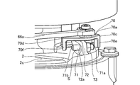
- FIG. 6 is a partial enlarged view of the vicinity of the holding portion 72.
- the contact member 71 is made of, for example, a bolt. Screw holes 72 a are formed in the holding portion 72. The screw hole 72 a penetrates the holding portion 72 in the axial direction of the contact member 71.
- the contact member 71 is screwed into the screw hole 72a. That is, the contact member 71 protrudes from both surfaces of the screw hole 72a.
- a hole into which a tool is fitted is formed on one end surface 71a in the axial direction.
- a nut 73 is screwed to the contact member 71 on the side of the one end surface 71 a with respect to the holding portion 72.
- the nut 73 is screwed into the contact member 71, and the nut 73 contacts the holding portion 72.
- the axial position of the contact member 71 with respect to the holding portion 72 is positioned.
- the main body 70a of the operation member 70 is provided with protrusions 70e and 70f (contacted parts) at one end 70c and the other end 70d, respectively.
- the protrusions 70e and 70f protrude from the main body 70a to the lower side (the turbine housing 4 side, the side opposite to the rod member 66a) in FIG.
- the contact members 71 and the holding portions 72 overlap the protrusions 70e and 70f in the vertical direction (the axial direction of the shaft 8) in FIG.
- the contact member 71 and the protrusions 70 e and 70 f overlap at the axial position of the link pin 67.
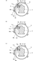
- FIG. 7A is a first diagram for explaining the operation of the actuating member 70.
- FIG. FIG. 7 (b) is a second view for explaining the operation of the actuating member 70.
- FIG. 7C is a third diagram for explaining the operation of the actuating member 70.
- a cross section of the variable displacement turbocharger C cut in a plane is seen from the lower side (the turbine housing 4 side) in FIG. Figure shows.
- the inside of the bearing housing 2 is simplified and hatched.
- the plane from which the variable displacement turbocharger C is cut is located in the gap S between the nut 73 and the turbine housing 4 shown in FIG. 6 and is perpendicular to the shaft 8.
- the opening degree of the nozzle vanes 62 is reduced.
- the nozzle throat width narrows.
- the opening degree of the nozzle vanes 62 becomes large.
- the nozzle throat width increases. That is, the force from the actuator 66 is transmitted from the rod member 66a to the actuating member 70 to rotate the actuating member 70. Accordingly, the drive shaft 63 connected to the actuating member 70 is actuated, and the nozzle vanes 62 are opened and closed. That is, by transmitting the force from the actuator 66, the nozzle vanes 62 are driven in conjunction with the actuating member 70.
- the actuating member 70 operates in a rotational direction (indicated by a double arrow in FIG. 7A) about the axis of the drive shaft 63 as the rod member 66a moves.
- the protrusions 70 e and 70 f are spaced apart in the actuating direction of the actuating member 70.
- the abutting member 71 is located between the operating directions of the protrusions 70e and 70f.
- the protrusions 70 e and 70 f face the contact member 71 from both sides in the actuating direction of the actuating member 70.
- the actuating member 70 operates clockwise from the position shown in FIG. 7 (a). As shown in FIG. 7B, the projection 70e abuts on one end surface 71a of the contact member 71. The actuation member 70 is no longer actuated clockwise. As a result, the drive shaft 63 connected to the actuating member 70 also does not rotate any more. The angle of the nozzle vanes 62 in the direction in which the opening degree decreases (hereinafter referred to as the closing direction) is restricted.
- the actuating member 70 operates counterclockwise from the position shown in FIG. 7 (a). As shown in FIG. 7C, the protrusion 70f contacts the other end surface 71b of the contact member 71. The actuation of the actuation member 70 no longer acts counterclockwise. As a result, the drive shaft 63 connected to the actuating member 70 also does not rotate any more. The angle of the nozzle vanes 62 in the direction in which the opening degree increases (hereinafter referred to as the opening direction) is restricted.
- One end surface 71 a of the abutting member 71 regulates the angle of the nozzle vane 62 in the closing direction.
- the other end surface 71 b of the contact member 71 regulates the angle of the nozzle vane 62 in the opening direction.
- the contact surface 70g of the one end surface 71a and the other end surface 71b of the contact member 71, and the contact surface 70g with the one end surface 71a of the contact member 71 among the protrusions 70e is formed in a planar shape.
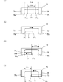
- FIG. 8A is a first diagram for explaining the position adjustment of the contact member 71.
- FIG. 8 (b) is a second view for explaining the position adjustment of the contact member 71.
- FIG. 8C is a third diagram for explaining the position adjustment of the contact member 71.
- FIG. 8D is a fourth diagram for explaining the position adjustment of the contact member 71.
- the sliding direction of the actuating member 70 is parallel to the axial direction of the contact member 71 for easy understanding.
- the actuating member 70 is shown deployed.
- the distance La between the contact surfaces 70g and 70h of the operation member 70 in the operation direction is a distance La
- the axial length of the contact member 71 is a length Lb.
- the subtraction value obtained by subtracting the length Lb from the distance La is the sum of the gap between the one end surface 71a and the contact surface 70g in the actuation direction and the gap between the other end surface 71b and the contact surface 70h in the actuation direction.
- the actuating member 70 can slide in the sliding direction by this subtraction value.
- a designed target value is set for the change width of the angle of the nozzle vanes 62.
- the distance at which the actuating member 70 operates is taken as a distance Lc.
- the dimensions of the contact member 71 and the actuating member 70 are designed such that the subtraction value obtained by subtracting the length Lb from the distance La becomes the distance Lc.
- the nozzle 66 is controlled to the restriction angle in the closing direction by the actuator 66. Thereafter, as shown in FIG. 8C, the axial position of the contact member 71 with respect to the support portion 42a is adjusted so that one end surface 71a of the contact member 71 contacts the contact surface 70g of the projection 70e. Be done.
- the other end surface 71b of the contact member 71 is separated from the protrusion 70f by an amount that the one end surface 71a of the contact member 71 approaches the protrusion 70e. Therefore, when the angle of the nozzle vane 62 changes by the target value from the state of FIG. 8C and becomes the restriction angle in the opening direction, as shown in FIG. 8D, the other end face 71b of the contact member 71. Contact with the contact surface 70h of the projection 70f.
- the restriction angle in the closing direction of the nozzle vanes 62 is adjusted, and at the same time, the restriction angle in the opening direction of the nozzle vanes 62 is adjusted. Therefore, position adjustment of the contact member 71 at the time of installation etc. becomes easy. Workability improves.
- the contact member 71 regulates the angle of both the opening direction and the closing direction of the nozzle vanes 62. Therefore, it is possible to reduce the number of parts as compared with the case where the stoppers are individually provided in the opening direction and the closing direction of the nozzle vanes 62 respectively.
- FIG. 9 is an explanatory view for explaining a first modification.
- the case where the one end surface 71a and the other end surface 71b of the contact member 71 and the contact surfaces 70g and 70h of the actuating member 70 are planar has been described.
- one end surface 171 a of the contact member 171 that regulates the angle in the closing direction of the nozzle vane 62 is formed by a curved surface.
- one end surface 171a of the contact member 171 is formed by a curved surface.
- the other end surface 171 b may be formed by a curved surface.
- Both the one end surface 171a and the other end surface 171b may be formed by a curved surface.
- the restriction angle in the closing direction of the nozzle vanes 62 is higher in required accuracy than the restriction angle in the opening direction. It is preferable that one end surface 171 a be formed as a curved surface and an error in the restriction angle of the nozzle vane 62 in the closing direction be suppressed.
- one or both of the contact surfaces 70g and 70h may be formed by a curved surface.
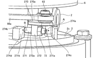
- FIG. 10 is an explanatory view for explaining a second modification.
- the case where the abutting members 71 and 171 are held by the holding portion 72 provided on the turbine housing 4 has been described.
- the holding portion 272 is formed on the actuating member 270.
- the actuating member 270 has a plate-like main portion 270a.
- the main body 270 a is located on the lower side (the turbine housing 4 side) in FIG. 10 with respect to the rod member 66 a of the actuator 66.
- the main body 270a is connected to the rod member 66a.
- the holding portion 272 is provided on the lower side (the turbine housing 4 side, the opposite side of the rod member 66a) in FIG. 10 of the main body portion 270a.
- the actuating member 270 and the holding portion 272 are located between the turbine housing 4 and the compressor housing 6.
- the holding portion 272 holds the contact member 271.
- the contact member 271 is formed of, for example, a bolt. Screw holes 272a are formed in the holding portion 272 as in the above-described embodiment. The contact member 271 is screwed into the screw hole 272a.
- a nut 73 is screwed into the contact member 271 from the side of one end surface 271 a in the axial direction.
- the nut 73 abuts on the holding portion 272.
- the axial position of the contact member 271 with respect to the holding portion 272 is determined.
- two protrusions 274 a and 274 b are provided in a fastening portion 2 c with the turbine housing 4.
- the protrusions 274a and 274b project from the fastening portion 2c to the compressor housing 6 side.
- the protrusions 274a and 274b overlap the contact member 271 in the vertical direction (the axial direction of the shaft 8) in FIG.
- the actuating member 270, the holding portion 272, and the abutting member 271 operate in the rotational direction about the axis of the drive shaft 63 as the rod member 66a moves.
- the protrusions 274 a and 274 b are separated in the operating direction of the contact member 271.
- the protrusion 274 a faces one end surface 271 a of the contact member 271 in the operating direction of the contact member 271.
- the protrusion 274 b faces the other end surface 271 b of the contact member 271 in the operating direction of the contact member 271.
- the contact member 271 operates in the direction of arrow A shown in FIG.
- One end surface 271a of the contact member 271 contacts the projection 274a.
- the abutment member 271 no longer operates in the direction of arrow A.
- the drive shaft 63 connected to the contact member 271 also does not rotate any more.
- the angle of the nozzle vanes 62 in the closing direction is regulated.
- the contact member 271 operates in the direction of the arrow B shown in FIG.
- the other end surface 271b of the contact member 271 contacts the projection 274b.
- the abutment member 271 no longer operates in the direction of the arrow B.
- the drive shaft 63 connected to the contact member 271 also does not rotate any more.
- the angle of the nozzle vanes 62 in the opening direction is restricted. That is, the protrusion 274 a regulates the angle of the nozzle vane 62 in the closing direction.
- the protrusion 274 b regulates the angle of the opening direction of the nozzle vanes 62.
- the dimension is designed such that the subtraction value corresponds to the target value of the change width in the angle of the nozzle vanes 62.
- the restriction angle in the opening direction of the nozzle vanes 62 is adjusted at the same time the restriction angle in the closing direction of the nozzle vanes 62 is adjusted.
- the workability of position adjustment of the contact member 71 can be improved.
- the nut 73 may be screwed to the one end surface 71 a side of the holding portion 72.
- the other end surface 71b is outside the one end surface 71a (a side away from the bearing housing 2) It is suitable for). Therefore, attachment of the nut 73 becomes easy.
- the case where the contact members 71, 171, and 271 are formed by bolts has been described.
- the case where the holding portions 72, 272 have the screw holes 72a, 272a has been described.
- the contact members 71, 171, and 271 may not be bolts.
- the screw holes 72 a and 272 a may not be formed in the holding portions 72 and 272.
- the abutting members 71, 171, 271 may be welded or adhered to the holding portions 72, 272.
- one end surface 171a of the contact member 171 is formed to be a curved surface
- one end surface 271a of the contact member 271 may be formed in a curved surface.
- one or both of the contact surfaces 274c and 274d (see FIG. 10) of the protrusions 274a and 274b that contact the contact member 271 may be curved surfaces.
- the holding portions 72 and 272 are located between the turbine housing 4 and the compressor housing 6 .
- the holding portions 72 and 272 may be disposed at other positions.
- position adjustment of the contact members 71, 171 and 271 with respect to the holding portions 72 and 272 is a narrow-place operation. Therefore, the workability is greatly improved by the above-described configuration in which the restriction angle in the opening direction of the nozzle vanes 62 is adjusted at the same time as the restriction angle in the closing direction of the nozzle vanes 62 is adjusted.
- the actuating members 70 and 270 operate in the rotation direction about the axis of the drive shaft 63 as the rotation center.
- the actuating member 70, 270 may be, for example, a rod member 66a.
- the protrusions 70e and 70f provided on the actuating member 70 may be separated in the actuating direction of the rod member 66a (generally, in the axial direction of the rod member 66a).
- the contact member 271 may be held by the holding portion 272 provided in the turbine housing 4. The contact member 271 may be located between the protrusions 70e and 70f.
- the contact members 71 and 171 may be held by the holding portion 72 provided on the actuating member 70 (rod member 66a).
- the protrusions 274a and 274b provided on the turbine housing 4 may be separated in the operating direction of the rod member 66a (approximately, in the axial direction of the rod member 66a).
- the contact members 71 and 171 may be positioned between the protrusions 274a and 274b.
- the actuating members 70 and 270 operate in the direction of rotation about the axis of the drive shaft 63 as in the embodiment and the modification described above, the following effects can be obtained. That is, for example, as shown in FIGS. 7 (a), 7 (b), and 7 (c), the protrusions 70e and 70f of the actuating member 70 do not pinch the contact member 71 in the axial direction. Position adjustment of the contact member 71 with respect to the holding portion 72 is facilitated.
- the actuator 66 has been described as a mechanical type in which the diaphragm is operated to open and close.
- the actuator 66 may be configured by an electric motor.
- the actuator 66 is mechanical, it is suitable for the above-mentioned composition which can restrict the angle of the nozzle vane 62 mechanically rather than the case of the electric motor which can control the angle of the nozzle vane 62 by electrical control.
- the holding portion 72 is provided in the bearing housing 2 has been described.
- the holding portion 72 may be provided on the turbine housing 4 or the compressor housing 6.
- the protrusions 274 a and 274 b may be provided on the turbine housing 4 or the compressor housing 6.
- the present disclosure can be applied to a variable displacement turbocharger provided with an actuating member that operates by receiving the power of an actuator.
- Variable displacement turbocharger 2 Bearing housing (housing) 4 Turbine housing (housing) 6 Compressor housing (housing) 20 variable displacement mechanism 62 nozzle vane 66 actuator 70 actuating member 70 e protrusion (contacted portion) 70f projection (contact part) 70g contact surface 70h contact surface 71 contact member 71a one end surface 72 holding portion 72a screw hole 171 contact member 171a one end surface 270 actuating member 270a main portion 271 contact member 271a one end surface 272 holding portion 274a protrusion (abutment portion Contact part) 274b Projection (Abutment part)
Landscapes
- Engineering & Computer Science (AREA)
- Mechanical Engineering (AREA)
- General Engineering & Computer Science (AREA)
- Chemical & Material Sciences (AREA)
- Combustion & Propulsion (AREA)
- Supercharger (AREA)
- Control Of Turbines (AREA)
Abstract
可変容量型過給機は、ノズルベーンを有する可変容量機構と、ノズルベーンを駆動するアクチュエータ(ロッド部材66a)と、アクチュエータの動力を受けて作動する作動部材70と、作動部材70、および、ハウジング(ベアリングハウジング2)の一方に設けられた保持部72と、保持部72に保持された当接部材71と、作動部材70、および、ハウジングの他方に設けられ、当接部材71に対して、作動部材70の作動方向の両側から対向する2つの被当接部(突起部70e、70f)と、を備える。
Description
本開示は、アクチュエータの動力を受けて作動する作動部材を備えた可変容量型過給機に関する。
従来、可変容量型の過給機が普及している。このような過給機では、タービンスクロール流路からタービンインペラに排気ガスを導く流路に、複数のノズルベーンが環状に整列配置される。ノズルベーンは翼軸に取り付けられる。翼軸の回転に伴って、ノズルベーンの角度が流路内で変化する。流路幅(所謂ノズルスロート幅)が変化して流路を流通する排気ガスの流量が制御される。
例えば、特許文献1では、駆動軸にアームが取り付けられる。駆動軸は、アクチュエータと翼軸を連結する連結部材の一つである。タービンハウジングに設けられた2つのストッパの間に、アームの先端側が位置している。そして、2つのストッパによって、アームの作動が規制される。こうして、ノズルベーンの角度(ノズルスロート幅の最大幅および最小幅)が規制される。また、2つのストッパはボルトで構成されている。2つのストッパそれぞれのタービンハウジングに対する軸方向の位置調整が可能となっている。
上記のストッパの位置調整は、2つのストッパそれぞれに対して行われる。そのため、作業に時間がかかってしまう。
そこで、本開示の目的は、設置時の開度調整を容易にすることができる可変容量型過給機を提供することである。
上記課題を解決するために、本開示の一態様に係る可変容量型過給機は、ノズルベーンを有する可変容量機構と、ノズルベーンを駆動するアクチュエータと、アクチュエータの動力を受けて作動する作動部材と、作動部材、および、ハウジングの一方に設けられた保持部と、保持部に保持された当接部材と、作動部材、および、ハウジングの他方に設けられ、当接部材に対して、作動部材の作動方向の両側から対向する2つの被当接部と、を備える。
当接部材は、ボルトで構成され、保持部は、ボルトが螺合するネジ孔を有してもよい。
当接部材の一端面、および、当接部材と当接する被当接部の当接面の一方または双方は、曲面であってもよい。
保持部は、タービンハウジングとコンプレッサハウジングとの間に位置してもよい。
本開示によれば、設置時の開度調整を容易にすることができる。
以下に添付図面を参照しながら、本開示の一実施形態について詳細に説明する。実施形態に示す寸法、材料、その他具体的な数値等は、理解を容易とするための例示にすぎず、特に断る場合を除き、本開示を限定するものではない。なお、本明細書および図面において、実質的に同一の機能、構成を有する要素については、同一の符号を付することにより重複説明を省略する。また本開示に直接関係のない要素は図示を省略する。
図1は、可変容量型過給機Cの概略断面図である。以下では、図1に示す矢印L方向を可変容量型過給機Cの左側として説明する。図1に示す矢印R方向を可変容量型過給機Cの右側として説明する。図1に示すように、可変容量型過給機Cは、過給機本体1を備える。過給機本体1は、ベアリングハウジング2(ハウジング)を備える。ベアリングハウジング2の左側には、締結ボルト3によってタービンハウジング4(ハウジング)が連結される。ベアリングハウジング2の右側には、締結ボルト5によってコンプレッサハウジング6(ハウジング)が連結される。ベアリングハウジング2、タービンハウジング4、コンプレッサハウジング6は、一体化されている。
ベアリングハウジング2には、収容孔2aが形成されている。収容孔2aは、可変容量型過給機Cの左右方向に貫通する。収容孔2aには、ラジアル軸受7(本実施形態では一例として、セミフローティング軸受を図1に示す)が収容される。ラジアル軸受7によって、シャフト8が回転自在に軸支されている。シャフト8の左端部には、タービンインペラ9が設けられる。タービンインペラ9がタービンハウジング4内に回転自在に収容されている。また、シャフト8の右端部には、コンプレッサインペラ10が設けられる。コンプレッサインペラ10がコンプレッサハウジング6内に回転自在に収容されている。
コンプレッサハウジング6には、吸気口11が形成されている。吸気口11は、可変容量型過給機Cの右側に開口する。吸気口11は、不図示のエアクリーナに接続される。また、締結ボルト5によってベアリングハウジング2とコンプレッサハウジング6とが連結された状態では、ディフューザ流路12が形成される。ディフューザ流路12は、ベアリングハウジング2とコンプレッサハウジング6の対向面によって形成される。ディフューザ流路12は、空気を昇圧する。ディフューザ流路12は、シャフト8の径方向内側から外側に向けて環状に形成される。ディフューザ流路12は、シャフト8の径方向内側において、コンプレッサインペラ10を介して吸気口11に連通している。
また、コンプレッサハウジング6には、コンプレッサスクロール流路13が設けられている。コンプレッサスクロール流路13は環状である。コンプレッサスクロール流路13は、例えば、ディフューザ流路12よりもシャフト8の径方向外側に位置する。コンプレッサスクロール流路13は、不図示のエンジンの吸気口と連通する。コンプレッサスクロール流路13は、ディフューザ流路12にも連通している。したがって、コンプレッサインペラ10が回転すると、吸気口11からコンプレッサハウジング6内に空気が吸気される。当該吸気された空気は、コンプレッサインペラ10の翼間を流通する過程において増速増圧される。増圧増速された空気は、ディフューザ流路12およびコンプレッサスクロール流路13で昇圧(圧力回復)される。昇圧された空気は、エンジンに導かれる。
また、締結ボルト3によってベアリングハウジング2とタービンハウジング4とが連結された状態では、ベアリングハウジング2とタービンハウジング4の対向面間に間隙14が形成される。この間隙14は、流路xが構成される部分である。流路xには、後述するノズルベーン62が配置される。流路xを排気ガスが流通する。間隙14は、シャフト8(タービンインペラ9)の径方向内側から外側に向けて環状に形成されている。
また、タービンハウジング4には、排気口16が形成されている。排気口16は、タービンインペラ9を介してタービンスクロール流路15に連通する。排気口16は、タービンインペラ9の正面に臨む。排気口16は、不図示の排気ガス浄化装置に接続される。
タービンスクロール流路15は、不図示のガス流入口と連通する。ガス流入口には、エンジンから排出される排気ガスが導かれる。タービンスクロール流路15は、上記の流路xにも連通している。したがって、ガス流入口からタービンスクロール流路15に導かれた排気ガスは、流路xおよびタービンインペラ9を介して排気口16に導かれる。すなわち、流路xは、タービンスクロール流路15からタービンインペラ9に向かう流路となっている。排気ガスの流通過程においてタービンインペラ9が回転する。そして、上記のタービンインペラ9の回転力は、シャフト8を介してコンプレッサインペラ10に伝達される。空気は、コンプレッサインペラ10の回転力によって昇圧されて、エンジンの吸気口に導かれる。
このとき、タービンハウジング4に導かれる排気ガスの流量が変化すると、タービンインペラ9およびコンプレッサインペラ10の回転量が変化する。エンジンの運転状況によっては、所望の圧力に昇圧された空気をエンジンの吸気口に十分に導くことができなくなる場合がある。そこで、可変容量型過給機Cには、可変容量機構20が設けられている。
可変容量機構20は、タービンハウジング4の流路xの流路幅(後述するノズルスロート幅)を変化させる。可変容量機構20は、排気ガスの流量に応じて、タービンインペラ9に導かれる排気ガスの流速を変化させる。具体的に、可変容量機構20は、エンジンの回転数が低く排気ガスの流量が少ない場合には、流路xのノズル開度を小さくする。タービンインペラ9に導かれる排気ガスの流速が向上する。可変容量機構20は、少ない流量でもタービンインペラ9を回転させることができるようにする。以下に、可変容量機構20の構成について説明する。
可変容量機構20は、シュラウドリング21と、ノズルリング22とを備えている。シュラウドリング21は、タービンハウジング4側に設けられる。ノズルリング22は、シュラウドリング21に対向してベアリングハウジング2側に設けられる。流路xは、シュラウドリング21およびノズルリング22によって区画形成される。
シュラウドリング21は、本体部21aを有する。本体部21aは、薄板リング状である。本体部21aの内周縁には、突出部21bが形成されている。突出部21bは、排気口16側に突出する。また、ノズルリング22は、本体部22aを備えている。本体部22aは、薄板リング状である。本体部22aは、シュラウドリング21の本体部21aと直径が等しい。本体部22aは、シュラウドリング21と所定の間隔を維持して対向配置されている。
図2(a)は、図1の上側の破線部分の抽出図である。図2(b)は、図1の下側の一点鎖線部分の抽出図である。図2(b)に示すように、シュラウドリング21の本体部21aには、ピン軸孔23aが設けられている。ピン軸孔23aは、本体部21aを厚さ方向(シャフト8の軸方向)に貫通する。ピン軸孔23aは、周方向に等間隔で複数(本実施形態では3つ、図2(b)では1つのみ示す)形成されている。
また、ノズルリング22の本体部22aには、ピン軸孔25aが形成されている。ピン軸孔25aは、本体部22aを厚さ方向(シャフト8の軸方向)に貫通する。本体部22aは、周方向に等間隔で複数(本実施形態では3つ、図2(b)では1つのみ示す)形成されている。シュラウドリング21に形成されたピン軸孔23aと、ノズルリング22に形成されたピン軸孔25aとが、対向している。ピン軸孔23a、25aには、連結ピン24が挿通される。
具体的には、図2(b)に示すように、連結ピン24の一端が、ノズルリング22のピン軸孔25aに挿通される。連結ピン24の他端が、シュラウドリング21のピン軸孔23aに挿通される。連結ピン24は、周方向に等間隔に離隔して複数(本実施形態では3つ、図2(b)では1つのみ示す)配設されている。連結ピン24によって、シュラウドリング21とノズルリング22との対向間隔が一定に維持されている。
また、連結ピン24のうち、ノズルリング22のピン軸孔25aに挿通された一端が、ノズルリング22の右側に突出する。連結ピン24の突出部位がかしめられる。こうして、ノズルリング22の右側に、サポートリング30およびガイドリング40が取り付けられる。サポートリング30は、円筒状の部材で構成されている。サポートリング30は、板状の部材を屈曲させた断面形状をなしている(図1参照)。
図3は、サポートリング30およびガイドリング40の平面図である。図3において、図面手前側が図2(a)、図2(b)の右側に向いている。図3において、図面奥側が図2(a)、図2(b)の左側に向いている。サポートリング30は、図2(a)、図2(b)に示すように、フランジ部31と、筒部32と、底面部33(図3中、クロスハッチングで示す)を備えている。フランジ部31は環状である。筒部32は、フランジ部31の内周縁から左側(図3中、奥側)に起立する。底面部33は環状である。底面部33は、筒部32の左端部から径方向内側に屈曲する。
そして、図2(a)、図2(b)に示すように、ベアリングハウジング2とタービンハウジング4との対向面にフランジ部31が挟持される。この状態で、ベアリングハウジング2およびタービンハウジング4を締結ボルト3で締結することで、サポートリング30がタービンハウジング4内に保持される。
ガイドリング40は、環状の本体部41を有している。ガイドリング40の本体部41の内径は、サポートリング30の底面部33の内径と大凡等しい。本体部41は、底面部33に当接した状態で、筒部32の径方向内側に配置される。図3では、サポートリング30の底面部33のうち、径方向内側の一部が、ガイドリング40の本体部41に隠れている。
サポートリング30の底面部33には、サポート孔33aが、周方向に等間隔で3カ所設けられている。サポート孔33aには、連結ピン24の一端が挿通される。また、ガイドリング40の本体部41には、ガイド孔41aが3カ所設けられている。ガイド孔41aは、サポート孔33aに対向する位置に設けられる。サポート孔33aには、連結ピン24の一端が挿通される。サポート孔33a、ガイド孔41aに連結ピン24が挿通してかしめられる。こうして、シュラウドリング21、ノズルリング22、サポートリング30、および、ガイドリング40が締結される。
また、図3に示すように、ガイドリング40の本体部41には、支持片42が設けられている。支持片42は、周方向に離隔して複数(本実施形態では10個)設けられる。支持片42は、図2(a)、図2(b)に示すように、支持部42aと、脱落防止部42bとからなる。支持部42aは、本体部41から右側(図3中、手前側)に屈曲する。脱落防止部42bは、支持部42aから径方向外側に向けて屈曲する。脱落防止部42bは、本体部41から所定距離離間して対面する。
図4は、ガイドリング40に駆動リング50が支持された状態を示す図である。図4では、理解を容易とするため、サポートリング30の底面部33がクロスハッチングで示される。駆動リング50が底面部33よりも目の粗いクロスハッチングで示される。
駆動リング50は、環状の薄板部材によって構成される。支持片42の支持部42aは、駆動リング50の径方向内側に位置している。脱落防止部42bと底面部33との間に、駆動リング50が回転自在に支持される。図2(a)、図4に示すように、駆動リング50には、第1係合部51が形成されている。第1係合部51は、駆動リング50の内周側の端部から、径方向外側に向けて切り欠かれている。第1係合部51に伝達リンク60の一端が係合されている。
また、図2(b)、図4に示すように、駆動リング50の内周側の端部には、第2係合部52が1つ形成されている。第2係合部52は、第1係合部51と同様の形状をなす。第2係合部52に、リンク板61の一端が係合されている。リンク板61は、伝達リンク60と同様の形状をなす。
なお、伝達リンク60の他端側、および、リンク板61の他端側には、挿入孔60a、61aが形成されている。そして、図2(a)に示すように、挿入孔60aには、ノズルベーン62の翼軸62aが挿通されて取り付けられる。図2(b)に示すように、リンク板61の挿入孔61aには、駆動軸63の一端部63aが取り付けられている。
また、図2(a)に示すように、翼軸62aは、翼軸孔23b、25bに挿通されて回転自在に軸支されている。翼軸孔23bは、シュラウドリング21の本体部21aのうち、上記のピン軸孔23aよりも径方向内側に設けられる。翼軸孔23bは、本体部21aを厚さ方向(シャフト8の軸方向)に貫通する。翼軸孔23bは、本体部21aの周方向に間隔を空けて複数(本実施形態では、一例として等間隔で11個、図2(a)では1つのみ示す)形成されている。ここで、ノズルベーン62に対して、ノズルリング22と反対側のシュラウドリング21に形成される翼軸孔23bは省略してもよい。この場合、翼軸62aは、後述するノズルリング22に形成される翼軸孔25bのみに挿通されて回転自在に軸支されることとなる(片軸持ち)。
同様に、翼軸孔25bは、ノズルリング22の本体部22aのうち、上記のピン軸孔25aよりも径方向内側に設けられる。翼軸孔25bは、本体部22aを厚さ方向(シャフト8の軸方向)に貫通する。翼軸孔25bは、本体部22aの周方向に間隔を空けて複数(本実施形態では、一例として等間隔で11個、図2(a)では1つのみ示す)形成されている。シュラウドリング21に形成された翼軸孔23bと、ノズルリング22に形成された翼軸孔25bとが対向している。
そして、翼軸62aのうち、ノズルリング22の翼軸孔25bに挿通された一端が、ノズルリング22の右側に突出する。翼軸62aの一端は、伝達リンク60の挿入孔60aに挿通されている。翼軸62aの突出部位がかしめられる。翼軸62aに伝達リンク60が取り付けられる。
こうして、翼軸62aおよびノズルベーン62は、流路xに、タービンインペラ9の回転方向に離隔して複数、環状に整列配置される。駆動軸63は、図2(b)に示すように、駆動リング50の右側に延伸している。駆動軸63の延伸部分が軸受64に挿通されている。詳細には、軸受64は、環状の本体部64aを有する。本体部64aが取付孔2bに取り付けられる。取付孔2bは、ベアリングハウジング2に設けられる。また、本体部64aの軸受孔64bの内周面が軸受面となっている。軸受孔64bに駆動軸63が軸支されている。ここで、タービンインペラ9の回転方向は、シュラウドリング21の本体部21aの周方向、または、ノズルリング22の本体部22aの周方向と大凡同一方向となる。
すなわち、駆動軸63の一端部63aは、軸受孔64bから、図2(b)中、左側に突出する。一端部63aにリンク板61が係合する。また、駆動軸63の他端部63bは、軸受64の軸受孔64bから、図2(b)中、右側に突出する。他端部63b側には、駆動レバー65が一体的に連結されている。軸受64は、リンク板61と駆動レバー65の間に配されている。また、可変容量型過給機Cには、ベアリングハウジング2、タービンハウジング4、コンプレッサハウジング6の外部にアクチュエータ66が設けられている(図1参照)。駆動レバー65は、アクチュエータ66に連結されている。アクチュエータ66は、例えば、ダイアフラムが作動して開閉する機械式である。
そして、アクチュエータ66が駆動レバー65を駆動すると、図2(b)に示すように、駆動レバー65および駆動軸63が、駆動軸63の軸心を回転中心として作動(回動)する。駆動軸63と共にリンク板61が作動(回動)する。
そして、図4に示すリンク板61に、第2係合部52が回転方向に押圧される。駆動リング50が回転する。駆動リング50の回転によって、複数の第1係合部51それぞれに係合された伝達リンク60が回転方向に押圧されて作動する。伝達リンク60の作動に伴って複数の翼軸62aが回転する。翼軸62aの回転に伴って、複数のノズルベーン62が流路x内でノズルベーン62の径方向に対する角度を変化させる。このように、可変容量機構20は、リンク板61を作動させることで、複数のノズルベーン62の角度を同期して変化させる。可変容量機構20は、隣り合うノズルベーン62同士の流路幅(所謂ノズルスロート幅)を可変とする。すなわち、ノズルベーン62の開度を調整し、流路xの流路面積を可変とする。
駆動軸63のうち、軸受64に挿通されて軸支された部位(大径部63c)より、他端部63b側が小径の小径部63dとなっている。小径部63dと大径部63cの外径差によって段差面63eが形成されている。段差面63eは、駆動軸63の径方向に延在している。段差面63eは、小径部63dと大径部63cを繋ぐ面となっている。例えば、段差面63eは、駆動軸63の軸方向に直交する面である。小径部63dと大径部63cに連続する角部に、面取り形状やR形状などの曲面形状などが設けられてもよい。
駆動レバー65は、挿通部65aを有する。挿通部65aは、駆動軸63の軸方向に延伸する。挿通部65aは、例えば円筒状である。挿通部65aには、小径部63dが挿通される挿通孔65bが形成される。そして、小径部63dは、挿通部65aの挿通孔65bに、挿通部65aが段差面63eに当接する位置まで挿通されている。挿通部65aの外周面には、例えば、平板形状の連結部65cが形成されている。連結部65cは、挿通部65aの外周面のうち、図2(b)中、右側(軸受64の反対側)から、挿通孔65b(駆動軸63)の径方向に突出する。
挿通部65aには、挿通孔65bから外周面まで貫通する露出孔65dが形成されている。挿通部65aに挿通された駆動軸63の一部は、径方向に露出孔65dから露出している。駆動軸63のうち、露出孔65dから露出した部位は、挿通部65aに溶接される。このように、駆動レバー65は駆動軸63と係合している。
連結部65cには、リンク孔65eが形成されている。リンク孔65eは、図2(b)中、左右方向(駆動軸63の軸方向)に連結部65cを貫通する。リンク孔65eにリンクピン67が、図2(b)中、右側から挿通される。また、連結部65cのうち、図2(b)中、左側には、作動部材70が配されている。作動部材70は、板状の本体部70aを有する。本体部70aには、対向孔70bが設けられている。対向孔70bは、リンク孔65eと対向する位置に設けられる。対向孔70bは、図2(b)中、左右方向(駆動軸63の軸方向)に貫通する。リンクピン67は、リンク孔65eおよび対向孔70bに挿通される。リンクピン67のうちの左側の突出部位は、例えば、かしめられて取り付けられる。
また、リンクピン67のうち、リンク孔65eから図2(b)中、右側に突出した部位には、アクチュエータ66のロッド部材66aの先端部66bが接続されている。具体的には、例えば、ロッド部材66aの先端部66bに設けられた孔に、リンクピン67が径方向の隙間を空けて嵌合(挿通)される。ロッド部材66aが、リンクピン67に対して回転自在に接続されている。作動部材70は、連結部65cを挟んでロッド部材66aと係合する。こうして、ロッド部材66aに、連結部65cおよび作動部材70が連結(係合)されている。そのため、作動部材70と連結部65cの角度関係は、回転動作で変わらない。
アクチュエータ66からの動力を受けて、ロッド部材66aが、図2(b)中、上下方向に移動する。ロッド部材66aに押圧された駆動レバー65が、駆動軸63の中心軸を回転中心として回動する。そして、駆動レバー65と共に、駆動レバー65に取り付けられた駆動軸63が回転する。こうして、リンク板61は、駆動軸63の中心軸を回転中心とした回転方向に作動する。
ここでは、連結部65cにリンクピン67が取り付けられ、ロッド部材66aがリンクピン67に対して回転自在に接続される場合について説明した。ただし、ロッド部材66aにリンクピン67が取り付けられ、連結部65cがリンクピン67に対して回転自在に接続されてもよい。
ところで、ノズルベーン62の角度(ノズルスロート幅の最大幅および最小幅)を規制するため、タービンハウジング4には、図5に示す当接部材71が設けられている。
図5は、可変容量型過給機Cの外観斜視図である。図5に示すように、ベアリングハウジング2のうち、タービンハウジング4との締結部2cに保持部72が設けられている。保持部72は、締結部2cからコンプレッサハウジング6側に突出している。タービンハウジング4とコンプレッサハウジング6の間(ベアリングハウジング2に対し、シャフト8の径方向外側)に位置している。保持部72に当接部材71が保持される。
また、ロッド部材66aの先端部66bは、リンクピン67に接続される。先端部66bは、タービンハウジング4とコンプレッサハウジング6の間に位置している。そして、先端部66bに連結された作動部材70も、タービンハウジング4とコンプレッサハウジング6の間に位置する。
図6は、保持部72近傍の部分拡大図である。図6に示すように、当接部材71は、例えば、ボルトで構成されている。保持部72には、ネジ孔72aが形成されている。ネジ孔72aは、保持部72を当接部材71の軸方向に貫通する。ネジ孔72aには、当接部材71が螺合する。つまり、ネジ孔72aの両面から、当接部材71が突出している。当接部材71には、軸方向の一端面71aに、工具が嵌合する孔が形成されている。工具で当接部材71を軸周りに回転させることで、保持部72に対する軸方向の位置が変化する。つまり、当接部材71を一端から螺合できる。可変容量機構20に対する当接部材71の位置を変更できる。
また、当接部材71には、保持部72より一端面71a側に、ナット73が螺合している。ナット73を当接部材71に螺合させ、ナット73が保持部72に当接する。当接部材71の保持部72に対する軸方向の位置が、位置決めされる。
作動部材70の本体部70aには、一端部70cおよび他端部70dに、それぞれ突起部70e、70f(被当接部)が設けられている。突起部70e、70fは、本体部70aから、図6中、下側(タービンハウジング4側、ロッド部材66aと反対側)に突出している。当接部材71および保持部72は、突起部70e、70fと、図6中、上下方向(シャフト8の軸方向)の位置が重なっている。当接部材71と突起部70e、70fがリンクピン67の軸方向位置において重なる。
図7(a)は、作動部材70の動作を説明するための第1の図である。図7(b)は、作動部材70の動作を説明するための第2の図である。図7(c)は、作動部材70の動作を説明するための第3の図である。図7(a)、図7(b)、図7(c)には、可変容量型過給機Cを平面で切断した断面を、図6中、下側(タービンハウジング4側)から見た図を示す。ここでは、ベアリングハウジング2の内部を簡略化してハッチングで示す。可変容量型過給機Cを切断した平面は、図6に示すナット73とタービンハウジング4の隙間Sに位置し、かつ、シャフト8に垂直である。
ロッド部材66aの移動に伴って、駆動軸63が、図7(a)中、時計回りに作動すると、ノズルベーン62の開度が小さくなる。ノズルスロート幅が狭まる。また、駆動軸63が、図7(a)中、反時計回りに作動すると、ノズルベーン62の開度が大きくなる。ノズルスロート幅が拡がる。すなわち、アクチュエータ66からの力が、ロッド部材66aから作動部材70に伝達されて作動部材70が回動する。それに伴い、作動部材70と連結した駆動軸63が作動し、ノズルベーン62が開閉する。つまり、アクチュエータ66からの力の伝達により、作動部材70と連動しノズルベーン62が駆動している。
また、作動部材70は、ロッド部材66aの移動に伴って、駆動軸63の軸心を回転中心とした回転方向(図7(a)中、両矢印で示す)に作動する。突起部70e、70fは、作動部材70の作動方向に離間している。突起部70e、70fの作動方向の間に当接部材71が位置している。突起部70e、70fは、当接部材71に対して、作動部材70の作動方向の両側から対向する。
そして、作動部材70が、図7(a)に示す位置から時計回りに作動する。図7(b)に示すように、突起部70eが当接部材71の一端面71aに当接する。作動部材70が、それ以上、時計回りに作動しなくなる。その結果、作動部材70に連結された駆動軸63も、それ以上、回転しなくなる。開度が小さくなる方向(以下、閉方向と称す)のノズルベーン62の角度が規制される。
また、作動部材70が、図7(a)に示す位置から反時計回りに作動する。図7(c)に示すように、突起部70fが当接部材71の他端面71bに当接する。作動部材70の作動が、それ以上、反時計回りに作動しなくなる。その結果、作動部材70に連結された駆動軸63も、それ以上、回転しなくなる。開度が大きくなる方向(以下、開方向と称す)のノズルベーン62の角度が規制される。
当接部材71の一端面71aが、ノズルベーン62の閉方向の角度を規制する。当接部材71の他端面71bが、ノズルベーン62の開方向の角度を規制する。ここでは、当接部材71の一端面71a、他端面71b、および、突起部70eのうち、当接部材71の一端面71aとの当接面70g、突起部70fのうち、当接部材71の他端面71bとの当接面70hが、いずれも平面状に形成されている。
図8(a)は、当接部材71の位置調整を説明するための第1の図である。図8(b)は、当接部材71の位置調整を説明するための第2の図である。図8(c)は、当接部材71の位置調整を説明するための第3の図である。図8(d)は、当接部材71の位置調整を説明するための第4の図である。図8(a)、図8(b)、図8(c)、図8(d)では、理解を容易とするため、作動部材70の摺動方向が当接部材71の軸方向と平行になるように作動部材70が展開して示される。
図8(a)に示すように、作動部材70の当接面70g、70hの作動方向の離間距離が距離La、当接部材71の軸方向の長さが長さLbとする。このとき、距離Laから長さLbを減算した減算値は、一端面71aと当接面70gの作動方向の隙間と、他端面71bと当接面70hの作動方向の隙間の和となる。作動部材70は、この減算値分だけ、摺動方向に摺動することができる。
ところで、ノズルベーン62の角度の変化幅には、設計上の目標値が設定されている。ノズルベーン62の角度が目標値分だけ変化したとき、作動部材70が作動する距離を距離Lcとする。このとき、距離Laから長さLbを減算した減算値が、距離Lcとなるように、当接部材71および作動部材70の寸法が設計されている。
例えば、ノズルベーン62の閉方向の規制角度を調整する場合、図8(b)に示すように、アクチュエータ66で、ノズルベーン62が閉方向の規制角度に制御される。その後、図8(c)に示すように、当接部材71の一端面71aが突起部70eの当接面70gに接触するように、当接部材71の支持部42aに対する軸方向の位置が調整される。
そうすると、当接部材71の他端面71bは、当接部材71の一端面71aが突起部70eに近接した分だけ、突起部70fから離隔する。そのため、図8(c)の状態から、ノズルベーン62の角度が目標値分だけ変化して、開方向の規制角度になると、図8(d)に示すように、当接部材71の他端面71bが突起部70fの当接面70hに当接する。
このように、ノズルベーン62の閉方向の規制角度が調整されると同時に、ノズルベーン62の開方向の規制角度が調整される。そのため、設置時などの当接部材71の位置調整が容易となる。作業性が向上する。
また、当接部材71によって、ノズルベーン62の開方向および閉方向の双方の角度が規制される。そのため、ノズルベーン62の開方向および閉方向それぞれに、個別にストッパを設ける場合に比べて、部品点数を削減することが可能となる。
図9は、第1変形例を説明するための説明図である。上述した実施形態では、当接部材71の一端面71a、他端面71b、および、作動部材70の当接面70g、70hが平面状である場合について説明した。第1変形例では、当接部材171のうち、ノズルベーン62の閉方向の角度を規制する一端面171aが、曲面で形成される。
そのため、当接部材171の一端面171aが、作動部材70の当接面70gと当接するとき、当接面70gの向きが所期の姿勢からずれていても、平面同士の片当たりが回避される。その結果、ノズルベーン62の閉方向の規制角度の誤差を抑制することが可能となる。
ここでは、当接部材171の一端面171aが曲面で形成される場合について説明した。ただし、他端面171bが曲面で形成されてもよい。一端面171aおよび他端面171bの双方が曲面で形成されてもよい。ノズルベーン62の閉方向の規制角度は、開方向の規制角度よりも要求精度が高い。一端面171aを曲面で形成し、ノズルベーン62の閉方向の規制角度の誤差が抑制されるとよい。また、当接面70g、70hの一方または双方が、曲面で形成されてもよい。
図10は、第2変形例を説明するための説明図である。上述した実施形態および第1変形例では、当接部材71、171が、タービンハウジング4に設けられた保持部72に保持される場合について説明した。図10に示すように、第2変形例においては、保持部272が、作動部材270に形成される。
作動部材270は、板状の本体部270aを有する。本体部270aは、アクチュエータ66のロッド部材66aに対し、図10中、下側(タービンハウジング4側)に位置する。本体部270aは、ロッド部材66aに連結される。保持部272は、本体部270aのうち、図10中、下側(タービンハウジング4側、ロッド部材66aの反対側)に設けられる。これら作動部材270および保持部272は、タービンハウジング4とコンプレッサハウジング6の間に位置する。
保持部272は、当接部材271を保持する。当接部材271は、例えば、ボルトで構成される。保持部272には、上述した実施形態と同様、ネジ孔272aが形成されている。ネジ孔272aに当接部材271が螺合している。
当接部材271には、軸方向の一端面271a側からナット73が螺合している。ナット73が保持部272に当接する。当接部材271の保持部272に対する軸方向の位置が定まる。
ベアリングハウジング2のうち、タービンハウジング4との締結部2cには、2つの突起部274a、274b(被当接部)が設けられている。突起部274a、274bは、締結部2cからコンプレッサハウジング6側に突出している。突起部274a、274bは、当接部材271と、図10中、上下方向(シャフト8の軸方向)の位置が重なっている。
作動部材270、保持部272、および、当接部材271は、ロッド部材66aの移動に伴って、駆動軸63の軸心を回転中心とした回転方向に作動する。突起部274a、274bは、当接部材271の作動方向に離間している。突起部274aは、当接部材271の一端面271aに、当接部材271の作動方向に対向する。突起部274bは、当接部材271の他端面271bに、当接部材271の作動方向に対向する。
当接部材271が、図10に示す矢印Aの向きに作動する。当接部材271の一端面271aが、突起部274aに当接する。当接部材271が、それ以上、矢印Aの向きに作動しなくなる。その結果、当接部材271に連結された駆動軸63も、それ以上、回転しなくなる。閉方向のノズルベーン62の角度が規制される。
また、当接部材271が、図10に示す矢印Bの向きに作動する。当接部材271の他端面271bが、突起部274bに当接する。当接部材271が、それ以上、矢印Bの向きに作動しなくなる。その結果、当接部材271に連結された駆動軸63も、それ以上、回転しなくなる。開方向のノズルベーン62の角度が規制される。すなわち、突起部274aが、ノズルベーン62の閉方向の角度を規制する。突起部274bが、ノズルベーン62の開方向の角度を規制する。
また、突起部274a、274bの作動方向の離間距離から、当接部材271の軸方向の長さが減算されたとする。上述した実施形態と同様、第2変形例では、この減算値が、ノズルベーン62の角度における変化幅の目標値に対応するように、寸法が設計されている。
そして、当接部材271の保持部272に対する軸方向の位置を調整する場合、例えば、当接部材271の一端面271aを突起部274aに近接させる。その分、当接部材271の他端面271bが突起部274bから離隔する。
そのため、ノズルベーン62の閉方向の規制角度が調整されるのと同時に、ノズルベーン62の開方向の規制角度が調整される。当接部材71の位置調整の作業性が向上可能となる。
以上、添付図面を参照しながら本開示の一実施形態について説明したが、当業者であれば、特許請求の範囲に記載された範疇において、各種の変更例または修正例に想到し得ることは明らかであり、それらについても当然に技術的範囲に属するものと了解される。
また、上述した実施形態では、ナット73は、当接部材71のうち、保持部72より他端面71b側に螺合する場合について説明した。ただし、ナット73は、保持部72より一端面71a側に螺合してもよい。ナット73が、当接部材71のうち、保持部72より他端面71b側に螺合する場合、図5に示すように、他端面71bが一端面71aよりも外側(ベアリングハウジング2から離隔する側)に向いている。そのため、ナット73の取り付けが容易となる。
また、上述した実施形態および変形例では、当接部材71、171、271が、ボルトで構成される場合について説明した。保持部72、272が、ネジ孔72a、272aを有する場合について説明した。ただし、当接部材71、171、271は、ボルトでなくてもよい。保持部72、272には、ネジ孔72a、272aが形成されなくてもよい。この場合、例えば、当接部材71、171、271は、保持部72、272に溶接や接着されてもよい。
また、上述した第1変形例では、当接部材171の一端面171aが、曲面に形成される場合について説明した。上述した第2変形例においても、当接部材271の一端面271aが、曲面に形成されてもよい。また、突起部274a、274bのうち、当接部材271と当接する当接面274c、274d(図10参照)の一方または双方が、曲面であってもよい。
また、上述した実施形態および変形例では、保持部72、272は、タービンハウジング4とコンプレッサハウジング6との間に位置する場合について説明した。ただし、保持部72、272が、他の位置に配されてもよい。保持部72、272が、タービンハウジング4とコンプレッサハウジング6との間に位置する場合、当接部材71、171、271の保持部72、272に対する位置調整が、狭所作業となる。そのため、ノズルベーン62の閉方向の規制角度が調整されると同時に、ノズルベーン62の開方向の規制角度が調整される上記の構成によって、作業性が大きく改善する。
また、上述した実施形態および変形例では、作動部材70、270が、駆動軸63の軸心を回転中心とした回転方向に作動する場合について説明した。ただし、作動部材70、270は、例えば、ロッド部材66aであってもよい。
この場合、作動部材70(ロッド部材66a)に設けられた突起部70e、70fが、ロッド部材66aの作動方向(大凡、ロッド部材66aの軸方向)に離間してもよい。そして、当接部材271は、タービンハウジング4に設けられた保持部272に保持されてもよい。突起部70e、70fの間に当接部材271が位置してもよい。
また、当接部材71、171は、作動部材70(ロッド部材66a)に設けられた保持部72に保持されてもよい。そして、タービンハウジング4に設けられた突起部274a、274bが、ロッド部材66aの作動方向(大凡、ロッド部材66aの軸方向)に離間してもよい。突起部274a、274bの間に当接部材71、171が位置してもよい。
ただし、上述した実施形態および変形例のように、作動部材70、270が駆動軸63の軸心を回転中心とした回転方向に作動する場合、以下の効果がある。すなわち、例えば、図7(a)、図7(b)、図7(c)に示すように、作動部材70の突起部70e、70fが、当接部材71を軸方向に挟むことがない。当接部材71の保持部72に対する位置調整が容易となる。
また、上述した実施形態および変形例では、アクチュエータ66は、ダイアフラムが作動して開閉する機械式の場合について説明した。ただし、アクチュエータ66は、電動モータで構成されてもよい。アクチュエータ66が機械式の場合、ノズルベーン62の角度を電気制御で規制できる電動モータの場合よりも、ノズルベーン62の角度を機械的に規制できる上記の構成に適している。
また、上述した実施形態および第1変形例では、保持部72が、ベアリングハウジング2に設けられる場合について説明した。ただし、保持部72は、タービンハウジング4、または、コンプレッサハウジング6に設けられてもよい。また、上述した第2変形例では、突起部274a、274bが、ベアリングハウジング2に設けられる場合について説明した。ただし、突起部274a、274bは、タービンハウジング4、または、コンプレッサハウジング6に設けられてもよい。
本開示は、アクチュエータの動力を受けて作動する作動部材を備えた可変容量型過給機に利用することができる。
C 可変容量型過給機
2 ベアリングハウジング(ハウジング)
4 タービンハウジング(ハウジング)
6 コンプレッサハウジング(ハウジング)
20 可変容量機構
62 ノズルベーン
66 アクチュエータ
70 作動部材
70e 突起部(被当接部)
70f 突起部(被当接部)
70g 当接面
70h 当接面
71 当接部材
71a 一端面
72 保持部
72a ネジ孔
171 当接部材
171a 一端面
270 作動部材
270a 本体部
271 当接部材
271a 一端面
272 保持部
274a 突起部(被当接部)
274b 突起部(被当接部)
2 ベアリングハウジング(ハウジング)
4 タービンハウジング(ハウジング)
6 コンプレッサハウジング(ハウジング)
20 可変容量機構
62 ノズルベーン
66 アクチュエータ
70 作動部材
70e 突起部(被当接部)
70f 突起部(被当接部)
70g 当接面
70h 当接面
71 当接部材
71a 一端面
72 保持部
72a ネジ孔
171 当接部材
171a 一端面
270 作動部材
270a 本体部
271 当接部材
271a 一端面
272 保持部
274a 突起部(被当接部)
274b 突起部(被当接部)
Claims (8)
- ノズルベーンを有する可変容量機構と、
前記ノズルベーンを駆動するアクチュエータと、
前記アクチュエータの動力を受けて作動する作動部材と、
前記作動部材、および、ハウジングの一方に設けられた保持部と、
前記保持部に保持された当接部材と、
前記作動部材、および、前記ハウジングの他方に設けられ、前記当接部材に対して、前記作動部材の作動方向の両側から対向する2つの被当接部と、
を備える可変容量型過給機。 - 前記当接部材は、ボルトで構成され、
前記保持部は、前記ボルトが螺合するネジ孔を有する請求項1に記載の可変容量型過給機。 - 前記当接部材の一端面、および、前記当接部材と当接する前記被当接部の当接面の一方または双方は、曲面である請求項1に記載の可変容量型過給機。
- 前記当接部材の一端面、および、前記当接部材と当接する前記被当接部の当接面の一方または双方は、曲面である請求項2に記載の可変容量型過給機。
- 前記保持部は、タービンハウジングとコンプレッサハウジングとの間に位置する請求項1に記載の可変容量型過給機。
- 前記保持部は、タービンハウジングとコンプレッサハウジングとの間に位置する請求項2に記載の可変容量型過給機。
- 前記保持部は、タービンハウジングとコンプレッサハウジングとの間に位置する請求項3に記載の可変容量型過給機。
- 前記保持部は、タービンハウジングとコンプレッサハウジングとの間に位置する請求項4に記載の可変容量型過給機。
Priority Applications (1)
| Application Number | Priority Date | Filing Date | Title |
|---|---|---|---|
| JP2018532854A JP6642718B2 (ja) | 2016-08-08 | 2017-06-16 | 可変容量型過給機 |
Applications Claiming Priority (2)
| Application Number | Priority Date | Filing Date | Title |
|---|---|---|---|
| JP2016-155705 | 2016-08-08 | ||
| JP2016155705 | 2016-08-08 |
Publications (1)
| Publication Number | Publication Date |
|---|---|
| WO2018029985A1 true WO2018029985A1 (ja) | 2018-02-15 |
Family
ID=61161868
Family Applications (1)
| Application Number | Title | Priority Date | Filing Date |
|---|---|---|---|
| PCT/JP2017/022300 Ceased WO2018029985A1 (ja) | 2016-08-08 | 2017-06-16 | 可変容量型過給機 |
Country Status (2)
| Country | Link |
|---|---|
| JP (1) | JP6642718B2 (ja) |
| WO (1) | WO2018029985A1 (ja) |
Citations (6)
| Publication number | Priority date | Publication date | Assignee | Title |
|---|---|---|---|---|
| JP2001207856A (ja) * | 2000-01-24 | 2001-08-03 | Mitsubishi Heavy Ind Ltd | 可変ターボチャージャ |
| EP1564380A1 (de) * | 2004-02-17 | 2005-08-17 | BorgWarner Inc. | Turbineneinheit sowie Leitgitter und Verstellring hierfür |
| JP3714041B2 (ja) * | 1999-07-12 | 2005-11-09 | 三菱ふそうトラック・バス株式会社 | 可変ノズルベーン付き過給機 |
| JP2009537727A (ja) * | 2006-05-19 | 2009-10-29 | ボーグワーナー・インコーポレーテッド | ターボチャージャ |
| JP2013072400A (ja) * | 2011-09-28 | 2013-04-22 | Mitsubishi Heavy Ind Ltd | ターボチャージャ用ノズルベーン開度規制ストッパ構造 |
| JP2013526679A (ja) * | 2010-05-19 | 2013-06-24 | ボーグワーナー インコーポレーテッド | ターボチャージャ |
-
2017
- 2017-06-16 WO PCT/JP2017/022300 patent/WO2018029985A1/ja not_active Ceased
- 2017-06-16 JP JP2018532854A patent/JP6642718B2/ja active Active
Patent Citations (6)
| Publication number | Priority date | Publication date | Assignee | Title |
|---|---|---|---|---|
| JP3714041B2 (ja) * | 1999-07-12 | 2005-11-09 | 三菱ふそうトラック・バス株式会社 | 可変ノズルベーン付き過給機 |
| JP2001207856A (ja) * | 2000-01-24 | 2001-08-03 | Mitsubishi Heavy Ind Ltd | 可変ターボチャージャ |
| EP1564380A1 (de) * | 2004-02-17 | 2005-08-17 | BorgWarner Inc. | Turbineneinheit sowie Leitgitter und Verstellring hierfür |
| JP2009537727A (ja) * | 2006-05-19 | 2009-10-29 | ボーグワーナー・インコーポレーテッド | ターボチャージャ |
| JP2013526679A (ja) * | 2010-05-19 | 2013-06-24 | ボーグワーナー インコーポレーテッド | ターボチャージャ |
| JP2013072400A (ja) * | 2011-09-28 | 2013-04-22 | Mitsubishi Heavy Ind Ltd | ターボチャージャ用ノズルベーン開度規制ストッパ構造 |
Also Published As
| Publication number | Publication date |
|---|---|
| JPWO2018029985A1 (ja) | 2018-12-27 |
| JP6642718B2 (ja) | 2020-02-12 |
Similar Documents
| Publication | Publication Date | Title |
|---|---|---|
| JP5134717B1 (ja) | 可変容量型ターボチャージャおよび可変ノズル機構の組付方法 | |
| JP4987971B2 (ja) | デュアルウェストゲートを具えたターボチャージャ | |
| CN102648341B (zh) | 叶片行程调节螺钉 | |
| CN105934589B (zh) | 角度测量方法、测定夹具 | |
| US20180363493A1 (en) | Nozzle drive mechanism, turbocharger, and variable-capacity turbocharger | |
| JP6806224B2 (ja) | 可変容量型過給機 | |
| WO2014002809A1 (ja) | 過給機 | |
| JP6631688B2 (ja) | ノズル駆動機構、過給機、および、可変容量型過給機 | |
| JPWO2018037970A1 (ja) | 可変容量型過給機 | |
| CN112041565B (zh) | 具有可变光阑机构的径流式压缩机 | |
| JP5050788B2 (ja) | 過給機 | |
| JP6642718B2 (ja) | 可変容量型過給機 | |
| CN111051749A (zh) | 双偏心阀 | |
| JP2013019304A (ja) | 圧縮機の可変ガイドベーン装置及びその組立方法並びに過給機 | |
| US10746091B2 (en) | Turbocharger that is configured to direct exhaust gas away from a contact surface | |
| JP5954411B2 (ja) | 過給機 | |
| JP6104838B2 (ja) | 検出装置、回転機械、及び検出装置の取付け方法 | |
| WO2004099586A1 (en) | Control valve and parts of a turbocharger and a turbocharger boosting system comprising the same | |
| US7140838B2 (en) | Control lever attachment with play compensation for blades with variable setting angles | |
| CN105283647B (zh) | 致动器的动力传递机构以及增压器 | |
| CN108138971B (zh) | 流量可变阀机构以及增压器 | |
| JP2020079589A (ja) | 軸受システム | |
| JP4551798B2 (ja) | 可変ターボ過給機 | |
| JP2014181590A (ja) | アクチュエータの動力伝達機構および過給機 | |
| WO2021070463A1 (ja) | 過給機 |
Legal Events
| Date | Code | Title | Description |
|---|---|---|---|
| WWE | Wipo information: entry into national phase |
Ref document number: 2018532854 Country of ref document: JP |
|
| 121 | Ep: the epo has been informed by wipo that ep was designated in this application |
Ref document number: 17839060 Country of ref document: EP Kind code of ref document: A1 |
|
| NENP | Non-entry into the national phase |
Ref country code: DE |
|
| 122 | Ep: pct application non-entry in european phase |
Ref document number: 17839060 Country of ref document: EP Kind code of ref document: A1 |