WO2018026013A1 - Steel sheet and plated steel sheet - Google Patents
Steel sheet and plated steel sheet Download PDFInfo
- Publication number
- WO2018026013A1 WO2018026013A1 PCT/JP2017/028472 JP2017028472W WO2018026013A1 WO 2018026013 A1 WO2018026013 A1 WO 2018026013A1 JP 2017028472 W JP2017028472 W JP 2017028472W WO 2018026013 A1 WO2018026013 A1 WO 2018026013A1
- Authority
- WO
- WIPO (PCT)
- Prior art keywords
- steel sheet
- less
- strength
- ratio
- area ratio
- Prior art date
Links
Images


Classifications
-
- C—CHEMISTRY; METALLURGY
- C22—METALLURGY; FERROUS OR NON-FERROUS ALLOYS; TREATMENT OF ALLOYS OR NON-FERROUS METALS
- C22C—ALLOYS
- C22C38/00—Ferrous alloys, e.g. steel alloys
-
- C—CHEMISTRY; METALLURGY
- C21—METALLURGY OF IRON
- C21D—MODIFYING THE PHYSICAL STRUCTURE OF FERROUS METALS; GENERAL DEVICES FOR HEAT TREATMENT OF FERROUS OR NON-FERROUS METALS OR ALLOYS; MAKING METAL MALLEABLE, e.g. BY DECARBURISATION OR TEMPERING
- C21D8/00—Modifying the physical properties by deformation combined with, or followed by, heat treatment
- C21D8/02—Modifying the physical properties by deformation combined with, or followed by, heat treatment during manufacturing of plates or strips
- C21D8/0221—Modifying the physical properties by deformation combined with, or followed by, heat treatment during manufacturing of plates or strips characterised by the working steps
- C21D8/0226—Hot rolling
-
- C—CHEMISTRY; METALLURGY
- C21—METALLURGY OF IRON
- C21D—MODIFYING THE PHYSICAL STRUCTURE OF FERROUS METALS; GENERAL DEVICES FOR HEAT TREATMENT OF FERROUS OR NON-FERROUS METALS OR ALLOYS; MAKING METAL MALLEABLE, e.g. BY DECARBURISATION OR TEMPERING
- C21D8/00—Modifying the physical properties by deformation combined with, or followed by, heat treatment
- C21D8/02—Modifying the physical properties by deformation combined with, or followed by, heat treatment during manufacturing of plates or strips
- C21D8/0247—Modifying the physical properties by deformation combined with, or followed by, heat treatment during manufacturing of plates or strips characterised by the heat treatment
- C21D8/0263—Modifying the physical properties by deformation combined with, or followed by, heat treatment during manufacturing of plates or strips characterised by the heat treatment following hot rolling
-
- C—CHEMISTRY; METALLURGY
- C21—METALLURGY OF IRON
- C21D—MODIFYING THE PHYSICAL STRUCTURE OF FERROUS METALS; GENERAL DEVICES FOR HEAT TREATMENT OF FERROUS OR NON-FERROUS METALS OR ALLOYS; MAKING METAL MALLEABLE, e.g. BY DECARBURISATION OR TEMPERING
- C21D9/00—Heat treatment, e.g. annealing, hardening, quenching or tempering, adapted for particular articles; Furnaces therefor
- C21D9/46—Heat treatment, e.g. annealing, hardening, quenching or tempering, adapted for particular articles; Furnaces therefor for sheet metals
-
- C—CHEMISTRY; METALLURGY
- C22—METALLURGY; FERROUS OR NON-FERROUS ALLOYS; TREATMENT OF ALLOYS OR NON-FERROUS METALS
- C22C—ALLOYS
- C22C38/00—Ferrous alloys, e.g. steel alloys
- C22C38/001—Ferrous alloys, e.g. steel alloys containing N
-
- C—CHEMISTRY; METALLURGY
- C22—METALLURGY; FERROUS OR NON-FERROUS ALLOYS; TREATMENT OF ALLOYS OR NON-FERROUS METALS
- C22C—ALLOYS
- C22C38/00—Ferrous alloys, e.g. steel alloys
- C22C38/002—Ferrous alloys, e.g. steel alloys containing In, Mg, or other elements not provided for in one single group C22C38/001 - C22C38/60
-
- C—CHEMISTRY; METALLURGY
- C22—METALLURGY; FERROUS OR NON-FERROUS ALLOYS; TREATMENT OF ALLOYS OR NON-FERROUS METALS
- C22C—ALLOYS
- C22C38/00—Ferrous alloys, e.g. steel alloys
- C22C38/004—Very low carbon steels, i.e. having a carbon content of less than 0,01%
-
- C—CHEMISTRY; METALLURGY
- C22—METALLURGY; FERROUS OR NON-FERROUS ALLOYS; TREATMENT OF ALLOYS OR NON-FERROUS METALS
- C22C—ALLOYS
- C22C38/00—Ferrous alloys, e.g. steel alloys
- C22C38/005—Ferrous alloys, e.g. steel alloys containing rare earths, i.e. Sc, Y, Lanthanides
-
- C—CHEMISTRY; METALLURGY
- C22—METALLURGY; FERROUS OR NON-FERROUS ALLOYS; TREATMENT OF ALLOYS OR NON-FERROUS METALS
- C22C—ALLOYS
- C22C38/00—Ferrous alloys, e.g. steel alloys
- C22C38/02—Ferrous alloys, e.g. steel alloys containing silicon
-
- C—CHEMISTRY; METALLURGY
- C22—METALLURGY; FERROUS OR NON-FERROUS ALLOYS; TREATMENT OF ALLOYS OR NON-FERROUS METALS
- C22C—ALLOYS
- C22C38/00—Ferrous alloys, e.g. steel alloys
- C22C38/04—Ferrous alloys, e.g. steel alloys containing manganese
-
- C—CHEMISTRY; METALLURGY
- C22—METALLURGY; FERROUS OR NON-FERROUS ALLOYS; TREATMENT OF ALLOYS OR NON-FERROUS METALS
- C22C—ALLOYS
- C22C38/00—Ferrous alloys, e.g. steel alloys
- C22C38/06—Ferrous alloys, e.g. steel alloys containing aluminium
-
- C—CHEMISTRY; METALLURGY
- C22—METALLURGY; FERROUS OR NON-FERROUS ALLOYS; TREATMENT OF ALLOYS OR NON-FERROUS METALS
- C22C—ALLOYS
- C22C38/00—Ferrous alloys, e.g. steel alloys
- C22C38/08—Ferrous alloys, e.g. steel alloys containing nickel
-
- C—CHEMISTRY; METALLURGY
- C22—METALLURGY; FERROUS OR NON-FERROUS ALLOYS; TREATMENT OF ALLOYS OR NON-FERROUS METALS
- C22C—ALLOYS
- C22C38/00—Ferrous alloys, e.g. steel alloys
- C22C38/12—Ferrous alloys, e.g. steel alloys containing tungsten, tantalum, molybdenum, vanadium, or niobium
-
- C—CHEMISTRY; METALLURGY
- C22—METALLURGY; FERROUS OR NON-FERROUS ALLOYS; TREATMENT OF ALLOYS OR NON-FERROUS METALS
- C22C—ALLOYS
- C22C38/00—Ferrous alloys, e.g. steel alloys
- C22C38/14—Ferrous alloys, e.g. steel alloys containing titanium or zirconium
-
- C—CHEMISTRY; METALLURGY
- C22—METALLURGY; FERROUS OR NON-FERROUS ALLOYS; TREATMENT OF ALLOYS OR NON-FERROUS METALS
- C22C—ALLOYS
- C22C38/00—Ferrous alloys, e.g. steel alloys
- C22C38/18—Ferrous alloys, e.g. steel alloys containing chromium
- C22C38/20—Ferrous alloys, e.g. steel alloys containing chromium with copper
-
- C—CHEMISTRY; METALLURGY
- C22—METALLURGY; FERROUS OR NON-FERROUS ALLOYS; TREATMENT OF ALLOYS OR NON-FERROUS METALS
- C22C—ALLOYS
- C22C38/00—Ferrous alloys, e.g. steel alloys
- C22C38/18—Ferrous alloys, e.g. steel alloys containing chromium
- C22C38/22—Ferrous alloys, e.g. steel alloys containing chromium with molybdenum or tungsten
-
- C—CHEMISTRY; METALLURGY
- C22—METALLURGY; FERROUS OR NON-FERROUS ALLOYS; TREATMENT OF ALLOYS OR NON-FERROUS METALS
- C22C—ALLOYS
- C22C38/00—Ferrous alloys, e.g. steel alloys
- C22C38/18—Ferrous alloys, e.g. steel alloys containing chromium
- C22C38/26—Ferrous alloys, e.g. steel alloys containing chromium with niobium or tantalum
-
- C—CHEMISTRY; METALLURGY
- C22—METALLURGY; FERROUS OR NON-FERROUS ALLOYS; TREATMENT OF ALLOYS OR NON-FERROUS METALS
- C22C—ALLOYS
- C22C38/00—Ferrous alloys, e.g. steel alloys
- C22C38/18—Ferrous alloys, e.g. steel alloys containing chromium
- C22C38/28—Ferrous alloys, e.g. steel alloys containing chromium with titanium or zirconium
-
- C—CHEMISTRY; METALLURGY
- C22—METALLURGY; FERROUS OR NON-FERROUS ALLOYS; TREATMENT OF ALLOYS OR NON-FERROUS METALS
- C22C—ALLOYS
- C22C38/00—Ferrous alloys, e.g. steel alloys
- C22C38/18—Ferrous alloys, e.g. steel alloys containing chromium
- C22C38/32—Ferrous alloys, e.g. steel alloys containing chromium with boron
-
- C—CHEMISTRY; METALLURGY
- C22—METALLURGY; FERROUS OR NON-FERROUS ALLOYS; TREATMENT OF ALLOYS OR NON-FERROUS METALS
- C22C—ALLOYS
- C22C38/00—Ferrous alloys, e.g. steel alloys
- C22C38/18—Ferrous alloys, e.g. steel alloys containing chromium
- C22C38/34—Ferrous alloys, e.g. steel alloys containing chromium with more than 1.5% by weight of silicon
-
- C—CHEMISTRY; METALLURGY
- C22—METALLURGY; FERROUS OR NON-FERROUS ALLOYS; TREATMENT OF ALLOYS OR NON-FERROUS METALS
- C22C—ALLOYS
- C22C38/00—Ferrous alloys, e.g. steel alloys
- C22C38/18—Ferrous alloys, e.g. steel alloys containing chromium
- C22C38/38—Ferrous alloys, e.g. steel alloys containing chromium with more than 1.5% by weight of manganese
-
- C—CHEMISTRY; METALLURGY
- C22—METALLURGY; FERROUS OR NON-FERROUS ALLOYS; TREATMENT OF ALLOYS OR NON-FERROUS METALS
- C22C—ALLOYS
- C22C38/00—Ferrous alloys, e.g. steel alloys
- C22C38/18—Ferrous alloys, e.g. steel alloys containing chromium
- C22C38/40—Ferrous alloys, e.g. steel alloys containing chromium with nickel
- C22C38/42—Ferrous alloys, e.g. steel alloys containing chromium with nickel with copper
-
- C—CHEMISTRY; METALLURGY
- C22—METALLURGY; FERROUS OR NON-FERROUS ALLOYS; TREATMENT OF ALLOYS OR NON-FERROUS METALS
- C22C—ALLOYS
- C22C38/00—Ferrous alloys, e.g. steel alloys
- C22C38/18—Ferrous alloys, e.g. steel alloys containing chromium
- C22C38/40—Ferrous alloys, e.g. steel alloys containing chromium with nickel
- C22C38/44—Ferrous alloys, e.g. steel alloys containing chromium with nickel with molybdenum or tungsten
-
- C—CHEMISTRY; METALLURGY
- C22—METALLURGY; FERROUS OR NON-FERROUS ALLOYS; TREATMENT OF ALLOYS OR NON-FERROUS METALS
- C22C—ALLOYS
- C22C38/00—Ferrous alloys, e.g. steel alloys
- C22C38/18—Ferrous alloys, e.g. steel alloys containing chromium
- C22C38/40—Ferrous alloys, e.g. steel alloys containing chromium with nickel
- C22C38/48—Ferrous alloys, e.g. steel alloys containing chromium with nickel with niobium or tantalum
-
- C—CHEMISTRY; METALLURGY
- C22—METALLURGY; FERROUS OR NON-FERROUS ALLOYS; TREATMENT OF ALLOYS OR NON-FERROUS METALS
- C22C—ALLOYS
- C22C38/00—Ferrous alloys, e.g. steel alloys
- C22C38/18—Ferrous alloys, e.g. steel alloys containing chromium
- C22C38/40—Ferrous alloys, e.g. steel alloys containing chromium with nickel
- C22C38/50—Ferrous alloys, e.g. steel alloys containing chromium with nickel with titanium or zirconium
-
- C—CHEMISTRY; METALLURGY
- C22—METALLURGY; FERROUS OR NON-FERROUS ALLOYS; TREATMENT OF ALLOYS OR NON-FERROUS METALS
- C22C—ALLOYS
- C22C38/00—Ferrous alloys, e.g. steel alloys
- C22C38/18—Ferrous alloys, e.g. steel alloys containing chromium
- C22C38/40—Ferrous alloys, e.g. steel alloys containing chromium with nickel
- C22C38/54—Ferrous alloys, e.g. steel alloys containing chromium with nickel with boron
-
- C—CHEMISTRY; METALLURGY
- C23—COATING METALLIC MATERIAL; COATING MATERIAL WITH METALLIC MATERIAL; CHEMICAL SURFACE TREATMENT; DIFFUSION TREATMENT OF METALLIC MATERIAL; COATING BY VACUUM EVAPORATION, BY SPUTTERING, BY ION IMPLANTATION OR BY CHEMICAL VAPOUR DEPOSITION, IN GENERAL; INHIBITING CORROSION OF METALLIC MATERIAL OR INCRUSTATION IN GENERAL
- C23C—COATING METALLIC MATERIAL; COATING MATERIAL WITH METALLIC MATERIAL; SURFACE TREATMENT OF METALLIC MATERIAL BY DIFFUSION INTO THE SURFACE, BY CHEMICAL CONVERSION OR SUBSTITUTION; COATING BY VACUUM EVAPORATION, BY SPUTTERING, BY ION IMPLANTATION OR BY CHEMICAL VAPOUR DEPOSITION, IN GENERAL
- C23C2/00—Hot-dipping or immersion processes for applying the coating material in the molten state without affecting the shape; Apparatus therefor
- C23C2/04—Hot-dipping or immersion processes for applying the coating material in the molten state without affecting the shape; Apparatus therefor characterised by the coating material
- C23C2/06—Zinc or cadmium or alloys based thereon
-
- C—CHEMISTRY; METALLURGY
- C23—COATING METALLIC MATERIAL; COATING MATERIAL WITH METALLIC MATERIAL; CHEMICAL SURFACE TREATMENT; DIFFUSION TREATMENT OF METALLIC MATERIAL; COATING BY VACUUM EVAPORATION, BY SPUTTERING, BY ION IMPLANTATION OR BY CHEMICAL VAPOUR DEPOSITION, IN GENERAL; INHIBITING CORROSION OF METALLIC MATERIAL OR INCRUSTATION IN GENERAL
- C23C—COATING METALLIC MATERIAL; COATING MATERIAL WITH METALLIC MATERIAL; SURFACE TREATMENT OF METALLIC MATERIAL BY DIFFUSION INTO THE SURFACE, BY CHEMICAL CONVERSION OR SUBSTITUTION; COATING BY VACUUM EVAPORATION, BY SPUTTERING, BY ION IMPLANTATION OR BY CHEMICAL VAPOUR DEPOSITION, IN GENERAL
- C23C2/00—Hot-dipping or immersion processes for applying the coating material in the molten state without affecting the shape; Apparatus therefor
- C23C2/34—Hot-dipping or immersion processes for applying the coating material in the molten state without affecting the shape; Apparatus therefor characterised by the shape of the material to be treated
- C23C2/36—Elongated material
- C23C2/40—Plates; Strips
- C23C2/405—Plates of specific length
-
- C—CHEMISTRY; METALLURGY
- C21—METALLURGY OF IRON
- C21D—MODIFYING THE PHYSICAL STRUCTURE OF FERROUS METALS; GENERAL DEVICES FOR HEAT TREATMENT OF FERROUS OR NON-FERROUS METALS OR ALLOYS; MAKING METAL MALLEABLE, e.g. BY DECARBURISATION OR TEMPERING
- C21D2211/00—Microstructure comprising significant phases
- C21D2211/002—Bainite
-
- C—CHEMISTRY; METALLURGY
- C21—METALLURGY OF IRON
- C21D—MODIFYING THE PHYSICAL STRUCTURE OF FERROUS METALS; GENERAL DEVICES FOR HEAT TREATMENT OF FERROUS OR NON-FERROUS METALS OR ALLOYS; MAKING METAL MALLEABLE, e.g. BY DECARBURISATION OR TEMPERING
- C21D2211/00—Microstructure comprising significant phases
- C21D2211/005—Ferrite
-
- C—CHEMISTRY; METALLURGY
- C21—METALLURGY OF IRON
- C21D—MODIFYING THE PHYSICAL STRUCTURE OF FERROUS METALS; GENERAL DEVICES FOR HEAT TREATMENT OF FERROUS OR NON-FERROUS METALS OR ALLOYS; MAKING METAL MALLEABLE, e.g. BY DECARBURISATION OR TEMPERING
- C21D8/00—Modifying the physical properties by deformation combined with, or followed by, heat treatment
- C21D8/02—Modifying the physical properties by deformation combined with, or followed by, heat treatment during manufacturing of plates or strips
- C21D8/04—Modifying the physical properties by deformation combined with, or followed by, heat treatment during manufacturing of plates or strips to produce plates or strips for deep-drawing
- C21D8/0421—Modifying the physical properties by deformation combined with, or followed by, heat treatment during manufacturing of plates or strips to produce plates or strips for deep-drawing characterised by the working steps
- C21D8/0426—Hot rolling
-
- C—CHEMISTRY; METALLURGY
- C21—METALLURGY OF IRON
- C21D—MODIFYING THE PHYSICAL STRUCTURE OF FERROUS METALS; GENERAL DEVICES FOR HEAT TREATMENT OF FERROUS OR NON-FERROUS METALS OR ALLOYS; MAKING METAL MALLEABLE, e.g. BY DECARBURISATION OR TEMPERING
- C21D8/00—Modifying the physical properties by deformation combined with, or followed by, heat treatment
- C21D8/02—Modifying the physical properties by deformation combined with, or followed by, heat treatment during manufacturing of plates or strips
- C21D8/04—Modifying the physical properties by deformation combined with, or followed by, heat treatment during manufacturing of plates or strips to produce plates or strips for deep-drawing
- C21D8/0447—Modifying the physical properties by deformation combined with, or followed by, heat treatment during manufacturing of plates or strips to produce plates or strips for deep-drawing characterised by the heat treatment
- C21D8/0463—Modifying the physical properties by deformation combined with, or followed by, heat treatment during manufacturing of plates or strips to produce plates or strips for deep-drawing characterised by the heat treatment following hot rolling
-
- C—CHEMISTRY; METALLURGY
- C22—METALLURGY; FERROUS OR NON-FERROUS ALLOYS; TREATMENT OF ALLOYS OR NON-FERROUS METALS
- C22C—ALLOYS
- C22C2200/00—Crystalline structure
- C22C2200/02—Amorphous
-
- C—CHEMISTRY; METALLURGY
- C22—METALLURGY; FERROUS OR NON-FERROUS ALLOYS; TREATMENT OF ALLOYS OR NON-FERROUS METALS
- C22C—ALLOYS
- C22C2204/00—End product comprising different layers, coatings or parts of cermet
-
- C—CHEMISTRY; METALLURGY
- C22—METALLURGY; FERROUS OR NON-FERROUS ALLOYS; TREATMENT OF ALLOYS OR NON-FERROUS METALS
- C22C—ALLOYS
- C22C38/00—Ferrous alloys, e.g. steel alloys
- C22C38/18—Ferrous alloys, e.g. steel alloys containing chromium
- C22C38/40—Ferrous alloys, e.g. steel alloys containing chromium with nickel
- C22C38/58—Ferrous alloys, e.g. steel alloys containing chromium with nickel with more than 1.5% by weight of manganese
-
- C—CHEMISTRY; METALLURGY
- C22—METALLURGY; FERROUS OR NON-FERROUS ALLOYS; TREATMENT OF ALLOYS OR NON-FERROUS METALS
- C22C—ALLOYS
- C22C49/00—Alloys containing metallic or non-metallic fibres or filaments
- C22C49/02—Alloys containing metallic or non-metallic fibres or filaments characterised by the matrix material
- C22C49/10—Refractory metals
- C22C49/11—Titanium
Definitions
- the present invention relates to a steel plate and a plated steel plate.
- the steel plates used for the suspension members are easily exposed to rainwater and the like, and when they are thinned, thickness reduction due to corrosion becomes a big problem, so corrosion resistance is also required.
- Patent Document 1 discloses that a steel sheet excellent in ductility, stretch flangeability, and material uniformity can be provided by limiting the size of TiC, for example, in order to solve the above-described problem of good stretch flangeability.
- Patent Document 2 discloses that a steel sheet having excellent stretch flangeability and fatigue characteristics can be provided by defining the type, size, and number density of oxides.
- Patent Document 3 discloses that by defining the area ratio of the ferrite phase and the hardness difference from the second phase, it is possible to provide a steel sheet that has a small variation in strength and is excellent in ductility and hole expansibility. Yes.
- Patent Documents 1 and 2 disclose that the hole expansibility is improved by defining only the structure observed with an optical microscope. However, it is unclear whether sufficient stretch flangeability can be secured even when the strain distribution is considered.
- Examples of methods for increasing the yield stress include (1) work hardening, (2) a microstructure mainly composed of low-temperature transformation phases (bainite and martensite) with a high dislocation density, and (3) solid solution strengthening elements. Or (4) strengthening precipitation.
- the dislocation density increases, so that the workability is greatly deteriorated.
- solid solution strengthening (3) there is a limit to the absolute value of the strengthening amount, and it is difficult to increase the yield stress to a sufficient extent. Therefore, in order to increase yield stress efficiently while obtaining high workability, elements such as Nb, Ti, Mo, and V are added, and precipitation strengthening of these alloy carbonitrides is carried out, thereby increasing the high yield stress. It is desirable to achieve
- high strength steel sheets using precipitation strengthening have a phenomenon in which fatigue strength is inferior due to softening of the steel sheet surface layer.
- On the surface of the steel sheet that is in direct contact with the rolling roll during hot rolling only the surface of the steel sheet is lowered due to the heat removal effect of the roll in contact with the steel sheet.
- the outermost layer of the steel sheet is less than the Ar 3 point, the microstructure and precipitates are coarsened, and the outermost layer of the steel sheet is softened. This is the main factor of deterioration of fatigue strength.
- the fatigue strength of a steel material is improved as the steel sheet outermost layer is hardened. For this reason, the present situation is that it is difficult to obtain high fatigue strength in high-tensile steel sheets using precipitation strengthening.
- the fatigue strength ratio is desirably 0.45 or more, and it is desirable to maintain a high balance between tensile strength and fatigue strength even in a high-strength hot-rolled steel sheet.
- the fatigue strength ratio is a value obtained by dividing the fatigue strength of a steel plate by the tensile strength. In general, the fatigue strength tends to increase as the tensile strength increases, but the fatigue strength ratio decreases for higher strength materials. For this reason, even if a steel plate with high tensile strength is used, the fatigue strength does not increase, and the weight reduction of the vehicle body, which is the purpose of increasing the strength, may not be realized.
- An object of the present invention is to provide a steel plate and a plated steel plate that are excellent in strict stretch flangeability, fatigue characteristics, and elongation while having high strength.
- the inventors have a total precipitate density of 10 10 pieces / mm 3 or more of Ti (C, N) and Nb (C, N) having an equivalent circle diameter of 10 nm or less and a depth of 20 ⁇ m from the surface. It has been found that if the ratio (Hvs / Hvc) between the hardness (Hvs) and the hardness at the center of the plate thickness (Hvc) is 0.85 or more, excellent fatigue characteristics can be obtained.
- the present invention is based on the above-described new knowledge regarding the ratio of crystal grains having an orientation difference in the crystal grains of 5 to 14 ° to the total crystal grains and the new knowledge regarding the ratio of hardness. It has been intensively studied and completed.
- the gist of the present invention is as follows.
- the tensile strength is 480 MPa or more, The ratio of the tensile strength and yield strength is 0.80 or more, The product of the tensile strength and the limit molding height in the vertical stretch flange test is 19500 mm ⁇ MPa or more, The steel sheet according to (1) or (2), wherein the fatigue strength ratio is 0.45 or more.
- the chemical component is mass%, Cr: 0.05-1.0%, and B: 0.0005-0.10%,
- the chemical component is mass%, Mo: 0.01 to 1.0%, Cu: 0.01 to 2.0%, and Ni: 0.01% to 2.0%,
- the chemical component is mass%, Ca: 0.0001 to 0.05%, Mg: 0.0001 to 0.05%, Zr: 0.0001 to 0.05%, and REM: 0.0001 to 0.05%,
- the present invention it is possible to provide a steel plate and a plated steel plate that can be applied to a member that is required to have severe ductility and stretch flangeability while having high strength, and that is excellent in fatigue characteristics. Thereby, the steel plate excellent in the collision characteristic is realizable.
- FIG. 1A is a perspective view showing a vertical molded product used in the vertical stretch flange test method.
- FIG. 1B is a plan view showing a vertical molded product used in the vertical stretch flange test method.
- the steel plate according to the present embodiment has C: 0.008 to 0.150%, Si: 0.01 to 1.70%, Mn: 0.60 to 2.50%, Al: 0.010 to 0.60.
- the chemical composition represented by Examples of the impurities include those contained in raw materials such as ore and scrap and those contained in the manufacturing process.
- C 0.008 to 0.150%
- C combines with Nb, Ti and the like to form precipitates in the steel sheet, and contributes to improving the strength of the steel by precipitation strengthening. If the C content is less than 0.008%, this effect cannot be sufficiently obtained. For this reason, C content shall be 0.008% or more.
- the C content is preferably 0.010% or more, more preferably 0.018% or more.
- the C content exceeds 0.150%, the orientation dispersion in bainite tends to be large, and the proportion of crystal grains having an in-grain orientation difference of 5 to 14 ° is insufficient.
- C content exceeds 0.150%, cementite harmful to stretch flangeability increases and stretch flangeability deteriorates. For this reason, C content shall be 0.150% or less.
- the C content is preferably 0.100% or less, more preferably 0.090% or less.
- Si: 0.01 to 1.70% functions as a deoxidizer for molten steel. If the Si content is less than 0.01%, this effect cannot be obtained sufficiently. For this reason, Si content shall be 0.01% or more.
- the Si content is preferably 0.02% or more, more preferably 0.03% or more.
- stretch flangeability deteriorates or surface flaws occur.
- the Si content exceeds 1.70% the transformation point increases too much, and it is necessary to increase the rolling temperature. In this case, recrystallization during hot rolling is remarkably promoted, and the proportion of crystal grains having an in-grain orientation difference of 5 to 14 ° is insufficient.
- Si content when the Si content exceeds 1.70%, surface flaws are likely to occur when a plating layer is formed on the surface of the steel sheet. For this reason, Si content shall be 1.70% or less.
- the Si content is preferably 1.60% or less, more preferably 1.50% or less, and still more preferably 1.40% or less.
- Mn 0.60 to 2.50% Mn contributes to improving the strength of the steel by solid solution strengthening or by improving the hardenability of the steel. If the Mn content is less than 0.60%, this effect cannot be sufficiently obtained. For this reason, Mn content shall be 0.60% or more.
- the Mn content is preferably 0.70% or more, more preferably 0.80% or more.
- Mn content exceeds 2.50%, the hardenability becomes excessive and the degree of orientation dispersion in bainite increases. As a result, the proportion of crystal grains having an orientation difference within the grains of 5 to 14 ° is insufficient, and the stretch flangeability deteriorates. For this reason, Mn content shall be 2.50% or less.
- the Mn content is preferably 2.30% or less, more preferably 2.10% or less.
- Al: 0.010 to 0.60% is effective as a deoxidizer for molten steel. If the Al content is less than 0.010%, this effect cannot be sufficiently obtained. For this reason, Al content shall be 0.010% or more.
- the Al content is preferably 0.020% or more, more preferably 0.030% or more.
- Al content shall be 0.60% or less.
- the Al content is preferably 0.50% or less, more preferably 0.40% or less.
- Ti and Nb precipitate finely in the steel as carbides (TiC, NbC), and improve the strength of the steel by precipitation strengthening. Moreover, Ti and Nb fix C by forming a carbide and suppress the generation of cementite that is harmful to stretch flangeability. That is, Ti and Nb are important for precipitating and strengthening TiC during annealing. Although details will be described later, a method of utilizing Ti and Nb in this embodiment will also be described here. In the manufacturing process, in the hot rolling stage (stage from hot rolling to winding), it is necessary to make Ti and Nb partly in a solid solution state.
- Nb precipitates are less likely to occur at 620 ° C. or lower. It is important to introduce dislocations by performing skin pass rolling before annealing. Next, Ti (C, N) and Nb (C, N) precipitate finely on the introduced dislocations in the annealing stage. In particular, the effect (fine precipitation of Ti (C, N) and Nb (C, N)) becomes remarkable in the vicinity of the steel sheet surface layer where the dislocation density increases. This effect makes it possible to satisfy Hvs / Hvc ⁇ 0.85 and achieve high fatigue characteristics. Moreover, the ratio of tensile strength to yield strength (yield ratio) can be set to 0.80 or more by precipitation strengthening of Ti and Nb.
- the total content of Ti and Nb is set to 0.015% or more.
- the total content of Ti and Nb is preferably 0.020% or more. When the total content of Ti and Nb is less than 0.015%, workability deteriorates and the frequency of cracks increases during rolling. Further, the Ti content is preferably 0.025% or more, more preferably 0.035% or more, and further preferably 0.025% or more.
- the Nb content is preferably 0.025% or more, more preferably 0.035% or more.
- the total content of Ti and Nb exceeds 0.200%, the proportion of crystal grains having an orientation difference of 5 to 14 ° in the grains is insufficient, and the stretch flangeability is greatly deteriorated. Therefore, the total content of Ti and Nb is 0.200% or less.
- the total content of Ti and Nb is preferably 0.150% or less.
- P 0.05% or less
- P is an impurity. Since P deteriorates toughness, ductility, weldability, etc., the lower the P content, the better. When the P content is more than 0.05%, the stretch flangeability is significantly deteriorated. Therefore, the P content is 0.05% or less.
- the P content is preferably 0.03% or less, more preferably 0.02% or less. Although the lower limit of the P content is not particularly defined, excessive reduction is not desirable from the viewpoint of production cost. For this reason, P content is good also as 0.005% or more.
- S 0.0200% or less
- S is an impurity. S not only causes cracking during hot rolling, but also forms A-based inclusions that degrade stretch flangeability. Therefore, the lower the S content, the better. When the S content exceeds 0.0200%, the stretch flangeability is significantly deteriorated. For this reason, S content shall be 0.0200% or less.
- the S content is preferably 0.0150% or less, and more preferably 0.0060% or less.
- the lower limit of the S content is not particularly defined, but excessive reduction is undesirable from the viewpoint of manufacturing cost. For this reason, S content is good also as 0.0010% or more.
- N 0.0060% or less
- N is an impurity. N forms a precipitate with Ti and Nb in preference to C, and reduces Ti and Nb effective for fixing C. Therefore, it is preferable that the N content is low. When the N content is more than 0.0060%, the stretch flangeability is significantly deteriorated. For this reason, N content shall be 0.0060% or less. The N content is preferably 0.0050% or less. The lower limit of the N content is not particularly defined, but excessive reduction is undesirable from the viewpoint of manufacturing cost. For this reason, N content is good also as 0.0010% or more.
- Cr, B, Mo, Cu, Ni, Mg, REM, Ca, and Zr are not essential elements, but are arbitrary elements that may be appropriately contained in the steel sheet within a predetermined amount.
- Cr: 0 to 1.0% Cr contributes to improving the strength of steel. Even if Cr is not contained, the intended purpose is achieved, but in order to sufficiently obtain this effect, the Cr content is preferably 0.05% or more. On the other hand, if the Cr content exceeds 1.0%, the above effect is saturated and the economic efficiency is lowered. For this reason, Cr content shall be 1.0% or less.
- B 0-0.10% B improves hardenability and increases the structural fraction of the low-temperature transformation generation phase that is a hard phase. Although the intended purpose is achieved even if B is not contained, in order to sufficiently obtain this effect, the B content is preferably 0.0005% or more. On the other hand, if the B content exceeds 0.10%, the above effect is saturated and the economic efficiency is lowered. Therefore, the B content is 0.10% or less.
- Mo 0 to 1.0%
- Mo has the effect of improving hardenability and forming carbides to increase strength. Although the intended purpose is achieved even if Mo is not contained, the Mo content is preferably 0.01% or more in order to sufficiently obtain this effect. On the other hand, if the Mo content exceeds 1.0%, ductility and weldability may deteriorate. For this reason, Mo content shall be 1.0% or less.
- Cu: 0-2.0% increases the strength of the steel sheet and improves corrosion resistance and scale peelability. Although the intended purpose is achieved even if Cu is not contained, in order to sufficiently obtain this effect, the Cu content is preferably 0.01% or more, more preferably 0.04% or more. . On the other hand, if the Cu content exceeds 2.0%, surface defects may occur. For this reason, the Cu content is 2.0% or less, preferably 1.0% or less.
- Ni 0-2.0%
- Ni increases the strength of the steel sheet and improves toughness. Even if Ni is not contained, the intended purpose is achieved, but in order to sufficiently obtain this effect, the Ni content is preferably 0.01% or more. On the other hand, if the Ni content exceeds 2.0%, the ductility is lowered. For this reason, Ni content shall be 2.0% or less.
- Ca, Mg, Zr and REM all improve the toughness by controlling the shape of sulfides and oxides. Although the intended purpose is achieved even if Ca, Mg, Zr and REM are not included, at least one selected from the group consisting of Ca, Mg, Zr and REM is sufficient to obtain this effect.
- the content of is preferably 0.0001% or more, more preferably 0.0005% or more.
- the content of any of Ca, Mg, Zr or REM exceeds 0.05%, stretch flangeability deteriorates. For this reason, all content of Ca, Mg, Zr, and REM shall be 0.05% or less.
- the steel sheet according to the present embodiment has a structure represented by ferrite: 5 to 60% and bainite: 40 to 95%.
- the area ratio of ferrite is preferably less than 50%, more preferably less than 40%, and even more preferably less than 30%.
- the coiling temperature of the hot-rolled steel sheet is set to 630 ° C. or less, and solute Ti and solute Nb are secured in the steel sheet. Close to transformation temperature. For this reason, a lot of bainite is contained in the microstructure of the steel sheet, and the transformation dislocation introduced simultaneously with the transformation increases the nucleation sites of TiC and NbC at the time of annealing, so that a greater precipitation strengthening is achieved.
- the area ratio of bainite is adjusted according to the required material properties.
- the area ratio of bainite is preferably more than 50%, which not only increases the strength increase due to precipitation strengthening, but also reduces coarse cementite with poor press formability and maintains good press formability.
- the area ratio of bainite is more preferably more than 60%, still more preferably more than 70%.
- the area ratio of bainite is 95% or less, preferably 80% or less.
- a part of Ti and Nb in the steel sheet is in a solid solution state at the hot rolling stage (stage from hot rolling to winding), and the surface layer is obtained by skin pass rolling after hot rolling.
- Ti (C, N) or Nb (C, N) is deposited on the surface layer using the introduced strain as a nucleation site.
- the fatigue characteristics are improved as described above. For this reason, it is important to complete the hot rolling at 630 ° C. or less where precipitation of Ti and Nb is difficult to proceed. That is, it is important to wind the hot rolled material at a temperature of 630 ° C. or lower.
- the structure of the steel sheet in the hot rolling stage includes bainite and martensite, it has a high dislocation density.
- bainite and martensite are tempered during annealing, the dislocation density decreases. If the annealing time is insufficient, the dislocation density remains high and the elongation is low. For this reason, it is preferable that the average dislocation density of the steel sheet after annealing is 1 ⁇ 10 14 m ⁇ 2 or less.
- the average dislocation density of the steel sheet is decreased.
- a decrease in dislocation density leads to a decrease in yield stress of steel.
- Ti (C, N) and Nb (C, N) are precipitated as the dislocation density decreases, so that a high yield stress is obtained.
- the dislocation density is measured by CAMP-ISIJ Vol.
- the average dislocation density is calculated from the half-value widths of (110), (211), and (220), according to “Method for evaluating dislocation density using X-ray diffraction” described in pp. 17 (2004) p396.
- the microstructure has the above-described characteristics, it is possible to achieve a high yield ratio and a high fatigue strength ratio that could not be achieved by a steel plate that has been subjected to precipitation strengthening according to the prior art. That is, even if the microstructure near the steel sheet surface layer is different from the microstructure at the center of the plate thickness and is mainly composed of ferrite and exhibits a coarse structure, the hardness near the steel sheet surface layer is Ti (C, N) during annealing. And Nb (C, N) precipitation reaches a hardness comparable to that of the steel plate center. As a result, the occurrence of fatigue cracks is suppressed, and the fatigue strength ratio increases.
- the ratio (area ratio) of each organization is obtained by the following method. First, a sample collected from a steel plate is etched with nital. After the etching, image analysis is performed on the tissue photograph obtained in the field of view of 300 ⁇ m ⁇ 300 ⁇ m at a position of 1 ⁇ 4 depth of the plate thickness using an optical microscope. By this image analysis, the area ratio of ferrite, the area ratio of pearlite, and the total area ratio of bainite and martensite are obtained. Next, image analysis is performed on a structural photograph obtained with a 300 ⁇ m ⁇ 300 ⁇ m field of view at a position of a depth of 1 ⁇ 4 of the plate thickness using an optical microscope using a sample that has undergone repeller corrosion.
- the total area ratio of retained austenite and martensite is obtained. Furthermore, the volume fraction of retained austenite is obtained by X-ray diffraction measurement using a sample that has been chamfered from the normal direction of the rolling surface to 1 ⁇ 4 depth of the plate thickness. Since the volume ratio of retained austenite is equivalent to the area ratio, this is defined as the area ratio of retained austenite. Then, the area ratio of martensite is obtained by subtracting the area ratio of retained austenite from the total area ratio of retained austenite and martensite, and the area ratio of bainite is obtained by subtracting the area ratio of martensite from the total area ratio of bainite and martensite. The area ratio is obtained. In this way, the area ratios of ferrite, bainite, martensite, retained austenite, and pearlite can be obtained.
- Precipitate density In order to obtain an excellent yield ratio (ratio between yield strength and tensile strength), Ti (C, N) and Nb (C, N) precipitated by tempering bainite rather than transformation strengthening by a hard phase such as martensite. ) And other precipitation strengthening is very important.
- the total precipitate density of Ti (C, N) and Nb (C, N) having an equivalent circle diameter of 10 nm or less effective for precipitation strengthening is set to 10 10 pieces / mm 3 or more. Thereby, a yield ratio of 0.80 or more can be realized.
- the precipitate having an equivalent circle diameter of more than 10 nm obtained as the square root of (major axis ⁇ minor axis) does not affect the characteristics obtained in the present invention.
- the precipitate size becomes finer, precipitation strengthening due to Ti (C, N) and Nb (C, N) is more effectively obtained, which may reduce the amount of alloy elements contained.
- the total precipitate density of Ti (C, N) and Nb (C, N) having an equivalent circle diameter of 10 nm or less is specified. Precipitation is observed by observing a replica sample prepared according to the method described in JP-A-2004-317203 with a transmission electron microscope.
- the field of view is set at a magnification of 5000 to 100000 times, and the number of Ti (C, N) and Nb (C, N) from 3 fields or more to 10 nm or less is counted. Then, a electrolyte weight from weight change before and after electrolysis, is converted into a volume weight from gravity 7.8ton / m 3. Then, the total precipitate density is calculated by dividing the counted number by the volume.
- the present inventors set the ratio of the hardness at the steel sheet surface layer and the hardness at the center of the steel sheet to 0. 0. It has been found that the fatigue characteristics are improved by setting it to 85 or more.
- the hardness of the steel sheet surface layer refers to the hardness at a depth of 20 ⁇ m from the surface to the inside in the cross section of the steel sheet, and this is indicated as Hvs.
- the hardness at the center of the steel sheet refers to the hardness at a position on the inner side of the sheet thickness from the steel sheet surface in the cross section of the steel sheet, and this is indicated as Hvc.
- the present inventors have found that when these ratios Hvs / Hvc are less than 0.85, the fatigue characteristics are deteriorated, whereas when Hvs / Hvc is 0.85 or more, the fatigue characteristics are improved. Therefore, Hvs / Hvc is set to 0.85 or more.
- the intra-grain orientation difference when a region surrounded by a grain boundary with an orientation difference of 15 ° or more and an equivalent circle diameter of 0.3 ⁇ m or more is defined as a crystal grain, the intra-grain orientation difference is 5 to 14
- the ratio of the crystal grains that are ° to the total crystal grains is 20 to 100% in terms of area ratio.
- the intra-grain orientation difference is determined using an electron beam backscattering diffraction pattern analysis (EBSD) method often used for crystal orientation analysis.
- EBSD electron beam backscattering diffraction pattern analysis
- the orientation difference in the grain is a value in the case where the boundary where the orientation difference is 15 ° or more is defined as a grain boundary in the structure, and a region surrounded by the grain boundary is defined as a crystal grain.
- Crystal grains having an orientation difference within the grain of 5 to 14 ° are effective for obtaining a steel sheet having an excellent balance between strength and workability.
- stretch flangeability can be improved while maintaining the desired steel sheet strength.
- the ratio of the crystal grains having an intra-grain orientation difference of 5 to 14 ° to the total crystal grains is 20% or more in terms of area ratio, desired steel plate strength and stretch flangeability can be obtained. Since the ratio of crystal grains having an orientation difference within a grain of 5 to 14 ° may be high, the upper limit is 100%.
- the proportion of crystal grains having an orientation difference within the grains of 5 to 14 ° is set to 20% or more. Crystal grains having an orientation difference of less than 5 ° in the grains are excellent in workability but are difficult to increase in strength. A crystal grain having an orientation difference of more than 14 ° within the grains does not contribute to the improvement of stretch flangeability because the deformability differs within the crystal grains.
- the proportion of crystal grains having an orientation difference within the grain of 5 to 14 ° can be measured by the following method.
- Crystal orientation information is obtained by EBSD analysis.
- the EBSD analysis was performed at an analysis speed of 200 to 300 points / second using an apparatus configured with a thermal field emission scanning electron microscope (JSMOL JSM-7001F) and an EBSD detector (TSL HIKARI detector). To do.
- JSMOL JSM-7001F thermal field emission scanning electron microscope
- TSL HIKARI detector EBSD detector
- a region having an orientation difference of 15 ° or more and an equivalent circle diameter of 0.3 ⁇ m or more is defined as a crystal grain, and an average orientation difference in the crystal grain is calculated.
- the ratio of crystal grains having an orientation difference within the grains of 5 to 14 ° is obtained.
- the crystal grains and the average orientation difference within the grains defined above can be calculated using software “OIM Analysis (registered trademark)” attached to the EBSD analyzer.
- the “intragranular orientation difference” in the present embodiment represents “Grain Orientation Spread (GOS)” which is the orientational dispersion within the crystal grains.
- Intragranular misorientation value is “Analysis of misorientation in plastic deformation of stainless steel by EBSD method and X-ray diffraction method”, Hidehiko Kimura et al., Transactions of the Japan Society of Mechanical Engineers (A), 71, 712, 2005 , P. As described in 1722-1728, it is obtained as an average value of misorientation between a reference crystal orientation and all measurement points in the same crystal grain.
- the reference crystal orientation is an orientation obtained by averaging all measurement points in the same crystal grain.
- the value of GOS can be calculated using software “OIM Analysis (registered trademark) Version 7.0.1” attached to the EBSD analyzer.
- the area ratio of each structure observed in an optical microscope structure such as ferrite and bainite is directly related to the ratio of crystal grains having an orientation difference within the grain of 5 to 14 °. is not.
- the ratio of crystal grains having an in-grain orientation difference of 5 to 14 ° is not necessarily the same. Therefore, the characteristics corresponding to the steel sheet according to this embodiment cannot be obtained only by controlling the area ratio of ferrite and the area ratio of bainite.
- the hole expansion test used as a test method corresponding to stretch flange formability leads to fracture without almost any circumferential strain distribution. For this reason, the strain and stress gradient around the fractured portion are different from those at the time of actual stretch flange molding. Moreover, the hole expansion test is not an evaluation reflecting the original stretch flange molding, such as an evaluation at the time when a break through the plate thickness occurs. On the other hand, in the vertical stretch flange test used in the present embodiment, the stretch flangeability in consideration of the strain distribution can be evaluated, so that the evaluation reflecting the original stretch flange molding is possible.
- a tensile strength of 480 MPa or more is obtained. That is, excellent tensile strength can be obtained.
- the upper limit of the tensile strength is not particularly limited. However, in the component range in this embodiment, the upper limit of the substantial tensile strength is about 1180 MPa.
- the tensile strength can be measured by preparing a No. 5 test piece described in JIS-Z2201 and performing a tensile test according to the test method described in JIS-Z2241.
- a yield ratio (ratio of tensile strength to yield strength) of 0.80 or more can be obtained. That is, an excellent yield ratio can be obtained.
- the upper limit of the yield ratio is not particularly limited. However, in the component range in this embodiment, the upper limit of the substantial yield ratio is about 0.96.
- the hot dip galvanized steel sheet and the alloyed hot dip galvanized steel sheet are manufactured by performing hot dip plating or galvannealed hot dip plating on the steel sheet according to this embodiment described above.
- alloy hot dipping means that hot dipping is applied to form a hot dipped layer on the surface, and then a fodder is applied to make the hot dipped layer as an alloyed hot dipped layer. Since the hot dip galvanized steel sheet and the alloyed hot dip galvanized steel sheet have the steel plate according to the present embodiment and the surface is provided with the hot dip plated layer or the alloyed hot dip plated layer, together with the effects of the steel plate according to the present embodiment. Excellent rust prevention can be achieved. Prior to plating, Ni or the like may be applied to the surface as pre-plating.
- the plated steel sheet according to the embodiment of the present invention has an excellent rust prevention property because a plating layer is formed on the surface of the steel sheet. Therefore, for example, when the member of an automobile is thinned using the plated steel sheet of the present embodiment, it is possible to prevent the service life of the automobile from being shortened due to corrosion of the member.
- Hot rolling includes rough rolling and finish rolling.
- a slab steel piece having the above-described chemical components is heated to perform rough rolling.
- the slab heating temperature is SRTmin ° C. or higher and 1260 ° C. or lower expressed by the following formula (1).
- SRTmin [7000 / ⁇ 2.75 ⁇ log ([Ti] ⁇ [C]) ⁇ ⁇ 273) + 10000 / ⁇ 4.29 ⁇ log ([Nb] ⁇ [C]) ⁇ ⁇ 273)] / 2 ⁇ (1)
- [Ti], [Nb], and [C] in the formula (1) indicate the contents of Ti, Nb, and C in mass%.
- slab heating temperature is lower than SRTmin ° C, Ti and / or Nb will not be sufficiently solutionized. If Ti and / or Nb do not form a solution during slab heating, it will be difficult to finely precipitate Ti and / or Nb as carbides (TiC, NbC) and improve the strength of the steel by precipitation strengthening. Further, when the slab heating temperature is lower than SRTmin ° C., it becomes difficult to fix C due to the formation of carbides (TiC, NbC) and suppress the generation of cementite that is harmful to burring properties. Further, when the slab heating temperature is lower than SRTmin ° C., the proportion of crystal grains having a crystal orientation difference within the grains of 5 to 14 ° tends to be insufficient. For this reason, slab heating temperature shall be more than SRTmin degreeC. On the other hand, when the slab heating temperature exceeds 1260 ° C., the yield decreases due to the scale-off. For this reason, slab heating temperature shall be 1260 degrees C or less.
- the cumulative strain in the subsequent three stages of finish rolling and the subsequent cooling it is possible to control the nucleation frequency and the subsequent growth rate of crystal grains having an in-grain misorientation of 5 to 14 °.
- the area ratio of crystal grains having a grain orientation difference of 5 to 14 ° in the steel sheet obtained after cooling More specifically, the dislocation density of austenite introduced by finish rolling is mainly related to the nucleation frequency, and the cooling rate after rolling is mainly related to the growth rate.
- the cumulative strain in the last three stages of the finish rolling is less than 0.5, the dislocation density of the austenite to be introduced is not sufficient, and the proportion of crystal grains having an orientation difference within the grain of 5 to 14 ° is less than 20%. . For this reason, the cumulative strain in the subsequent three stages is 0.5 or more.
- the cumulative strain in the third stage after finish rolling exceeds 0.6, austenite recrystallization occurs during hot rolling, and the accumulated dislocation density during transformation decreases. As a result, the proportion of crystal grains having an orientation difference within the grains of 5 to 14 ° is less than 20%. For this reason, the cumulative strain in the subsequent three stages is set to 0.6 or less.
- the cooling stop temperature of the first cooling is 750 ° C. or lower, preferably 740 ° C. or lower, more preferably 730 ° C. or lower, and further preferably 720 ° C. or lower.
- the holding time at 600 to 750 ° C. exceeds 10 seconds, cementite harmful to burring properties is likely to be generated. Further, if the holding time at 600 to 750 ° C. exceeds 10 seconds, it is often difficult to obtain a bainite having an area ratio of 40% or more, and further, a crystal having a crystal orientation difference within the grain of 5 to 14 ° The proportion of grains is insufficient. From the viewpoint of obtaining a high bainite fraction, the holding time is 10.0 seconds or less, preferably 9.5 seconds or less, more preferably 9.0 seconds or less, and even more preferably 8.5 seconds or less. . If the holding time at 600 to 750 ° C. is 0 second, it becomes difficult to obtain ferrite with an area ratio of 5% or more, and the proportion of crystal grains having an in-grain crystal orientation difference of 5 to 14 ° is insufficient. .
- the cooling rate of the second cooling is less than 30 ° C./s, cementite harmful to burring properties is likely to be generated, and the proportion of crystal grains having a crystal orientation difference of 5 to 14 ° is insufficient.
- the cooling stop temperature of the second cooling is less than 450 ° C., it becomes difficult to obtain a ferrite with an area ratio of 5% or more, and the ratio of crystal grains having a crystal orientation difference within the grains of 5 to 14 ° Run short.
- the cooling stop temperature of the second cooling is higher than 630 ° C., the ratio of crystal grains having an orientation difference in the grains of 5 to 14 ° is insufficient, or bainite having an area ratio of 40% or more is obtained. Is often difficult.
- the hot rolled steel sheet is wound up after the second cooling.
- the coiling temperature 630 ° C. or less, precipitation of alloy carbonitride at the stage of the steel sheet (stage from hot rolling to winding) is suppressed.
- This hot-rolled sheet has a structure containing 5 to 60% ferrite and 40 to 95% bainite by area ratio, is surrounded by grain boundaries having an orientation difference of 15 ° or more, and has an equivalent circle diameter of 0.1.
- a region having a size of 3 ⁇ m or more is defined as a crystal grain, the ratio of the crystal grains having an in-grain orientation difference of 5 to 14 ° to the total crystal grains is 20 to 100% in terms of area ratio.
- first skin pass rolling In the first skin pass rolling, the hot-rolled steel sheet is pickled and subjected to skin pass rolling at an elongation of 0.1 to 5.0% with respect to the pickled steel sheet.
- strain can be imparted to the surface of the steel plate.
- alloy carbonitrides are easily nucleated on the dislocation through this strain, and the surface layer is hardened.
- the elongation rate of skin pass rolling is less than 0.1%, sufficient strain cannot be imparted and the surface layer hardness Hvs does not increase.
- the elongation rate of skin pass rolling exceeds 5.0%, not only the surface layer but also the central part of the steel sheet is strained, and the workability of the steel sheet is inferior.
- the ferrite is recrystallized by subsequent annealing, and the elongation and hole expansion properties are improved.
- Ti, Nb, Mo, V are dissolved in the hot-rolled steel sheet having the chemical composition in the present embodiment and wound up at 630 ° C. or less, and these are regenerated by annealing. The crystal is remarkably delayed, and the elongation and hole expandability after annealing are not improved. For this reason, the elongation rate of skin pass rolling is set to 5.0% or less.
- Strain is applied according to the elongation rate of this skin pass rolling, and precipitation strengthening in the vicinity of the steel sheet surface layer during annealing proceeds according to the strain amount of the steel sheet surface layer from the viewpoint of improving the fatigue characteristics. For this reason, it is preferable that elongation rate shall be 0.4% or more. Further, from the viewpoint of workability of the steel sheet, the elongation is preferably set to 2.0% or less in order to prevent deterioration of workability due to the application of strain to the inside of the steel sheet. It can be seen that when the elongation percentage of the skin pass rolling is 0.1 to 5.0%, Hvs / Hvc is improved to 0.85 or more. Further, it can be seen that Hvs / Hvc ⁇ 0.85 when skin pass rolling is not performed (skin pass rolling elongation rate is 0%) or when skin pass rolling elongation rate exceeds 5.0%.
- Exceptional elongation can be obtained when the elongation percentage of the first skin pass rolling is 0.1 to 5.0%. Moreover, when the elongation rate of 1st skin pass rolling exceeds 5.0%, elongation is inferior and press moldability is inferior. When the elongation percentage of the first skin pass rolling exceeds 0% or 5%, the fatigue strength ratio is inferior.
- the same elongation and fatigue strength ratio can be obtained if the tensile strength is substantially the same.
- the elongation rate of the first skin pass rolling exceeds 5% (high skin pass region), it can be seen that even if the tensile strength is 490 MPa or more, the elongation is low and the fatigue strength ratio is also low.
- the maximum heating temperature shall be 750 degrees C or less.
- the main purpose of this annealing is not to temper the hard phase but to precipitate Ti and Nb that have been dissolved in the steel sheet.
- the final strength is determined by the alloy composition of the steel material and the fraction of each phase in the microstructure of the steel sheet. It is not influenced at all by the fraction of each phase in the microstructure of the steel sheet.
- Hvs / Hvc When the maximum heating temperature is in the range of 600 to 750 ° C., Hvs / Hvc is 0.85 or more.
- the steel plates according to the present embodiment are manufactured under conditions where the holding time (t) at 600 ° C. or higher satisfies the ranges of the formulas (4) and (5).
- Hvs / Hvc when the holding time (t) satisfies the ranges of the formulas (4) and (5), Hvs / Hvc is 0.85 or more.
- the steel sheet according to the present embodiment has a fatigue strength ratio of 0.45 or more when Hvs / Hvc is 0.85 or more.
- the surface layer is cured by precipitation strengthening, and Hvs / Hvc is 0.85 or more.
- the surface layer is sufficiently cured as compared with the hardness of the central portion of the steel plate.
- the steel sheet according to the present embodiment has a fatigue strength ratio of 0.45 or more. This is because the occurrence of fatigue cracks can be delayed by the hardening of the surface layer. The higher the surface layer hardness, the greater the effect.
- the steel plate After annealing, the steel plate is subjected to second skin pass rolling. Thereby, fatigue characteristics can be further improved.
- the elongation is set to 0.2 to 2.0%, preferably 0.5 to 1.0%. If the elongation is less than 0.2%, sufficient improvement in surface roughness and work hardening of only the surface layer cannot be obtained, and fatigue characteristics may not be improved sufficiently. For this reason, the elongation rate of the second skin pass rolling is set to 0.2% or more. On the other hand, if the elongation exceeds 2.0%, the steel sheet may be too hard-worked and press formability may be inferior. For this reason, the elongation percentage of the second skin pass rolling is set to 2.0% or less.
- the steel sheet according to the present embodiment can be obtained.
- the steel sheet by controlling in detail the component composition containing the alloy elements and the production conditions, the steel sheet has excellent formability, fatigue characteristics and collision safety that could not be achieved in the past, and has a tensile strength of 480 MPa or more. Can be manufactured.
- the second skin pass was performed after hot dip galvanizing, and when manufacturing the hot dip galvanized steel sheet, the second skin pass was performed after alloying treatment.
- the underline in Table 6 shows that it is out of the range suitable for manufacturing the steel sheet of the present invention.
- the total area ratio of retained austenite and martensite was obtained. Furthermore, the volume fraction of retained austenite was determined by X-ray diffraction measurement using a sample which was chamfered from the normal direction of the rolling surface to 1 ⁇ 4 depth of the plate thickness. Since the volume ratio of retained austenite is equivalent to the area ratio, this was defined as the area ratio of retained austenite. Then, the area ratio of martensite is obtained by subtracting the area ratio of retained austenite from the total area ratio of retained austenite and martensite, and the area of bainite by subtracting the area ratio of martensite from the total area ratio of bainite and martensite. Got the rate. Thus, the area ratios of ferrite, bainite, martensite, retained austenite, and pearlite were obtained.
- “Percentage of crystal grains with an orientation difference within the grain of 5 to 14 °” EBSD analysis of a vertical cross section in the rolling direction at a 1/4 depth position (1 / 4t part) of the plate thickness t from the steel sheet surface at a measuring interval of 0.2 ⁇ m in a region of 200 ⁇ m in the rolling direction and 100 ⁇ m in the normal direction of the rolling surface.
- the EBSD analysis is performed using an apparatus configured with a thermal field emission scanning electron microscope (JSMOL JSM-7001F) and an EBSD detector (TSL HIKARI detector) at an analysis speed of 200 to 300 points / second. Carried out.
Abstract
Description
質量%で、
C:0.008~0.150%、
Si:0.01~1.70%、
Mn:0.60~2.50%、
Al:0.010~0.60%、
Ti:0~0.200%、
Nb:0~0.200%、
Ti+Nb:0.015~0.200%、
Cr:0~1.0%、
B:0~0.10%、
Mo:0~1.0%、
Cu:0~2.0%、
Ni:0~2.0%、
Mg:0~0.05%、
REM:0~0.05%、
Ca:0~0.05%、
Zr:0~0.05%、
P:0.05%以下、
S:0.0200%以下、
N:0.0060%以下、かつ
残部:Fe及び不純物、
で表される化学組成を有し、
面積率で、
フェライト:5~60%、かつ
ベイナイト:40~95%、
で表される組織を有し、
方位差が15°以上の粒界によって囲まれ、かつ円相当径が0.3μm以上である領域を結晶粒と定義した場合に、粒内方位差が5~14°である結晶粒の全結晶粒に占める割合が面積率で20~100%であり、
円相当直径が10nm以下のTi(C,N)及びNb(C,N)の析出物密度が1010個/mm3以上であり、
表面から深さ20μmにおける硬度(Hvs)と、板厚中心の硬度(Hvc)との比(Hvs/Hvc)が、0.85以上であることを特徴とする鋼板。 (1)
% By mass
C: 0.008 to 0.150%,
Si: 0.01 to 1.70%,
Mn: 0.60 to 2.50%,
Al: 0.010 to 0.60%,
Ti: 0 to 0.200%,
Nb: 0 to 0.200%,
Ti + Nb: 0.015 to 0.200%,
Cr: 0 to 1.0%,
B: 0 to 0.10%,
Mo: 0 to 1.0%,
Cu: 0 to 2.0%,
Ni: 0 to 2.0%,
Mg: 0 to 0.05%,
REM: 0 to 0.05%,
Ca: 0 to 0.05%,
Zr: 0 to 0.05%,
P: 0.05% or less,
S: 0.0200% or less,
N: 0.0060% or less, and the balance: Fe and impurities,
Having a chemical composition represented by
In area ratio,
Ferrite: 5-60%, and bainite: 40-95%,
Having an organization represented by
When a region surrounded by a grain boundary with an orientation difference of 15 ° or more and an equivalent circle diameter of 0.3 μm or more is defined as a crystal grain, all crystals of the crystal grain with an in-grain orientation difference of 5 to 14 ° The proportion of grains in the area ratio is 20 to 100%,
The precipitate density of Ti (C, N) and Nb (C, N) having an equivalent circle diameter of 10 nm or less is 10 10 pieces / mm 3 or more,
A steel sheet, characterized in that the ratio (Hvs / Hvc) of the hardness (Hvs) at a depth of 20 μm from the surface to the hardness (Hvc) at the center of the plate thickness is 0.85 or more.
平均転位密度が1×10¹⁴m-2以下であることを特徴とする(1)に記載の鋼板。 (2)
The steel sheet according to (1), wherein the average dislocation density is 1 × 10 14 m −2 or less.
引張強度が480MPa以上であり、
前記引張強度と降伏強度との比が0.80以上であり、
前記引張強度と鞍型伸びフランジ試験における限界成形高さとの積が19500mm・MPa以上であり、
疲労強度比が0.45以上であることを特徴とする(1)又は(2)に記載の鋼板。 (3)
The tensile strength is 480 MPa or more,
The ratio of the tensile strength and yield strength is 0.80 or more,
The product of the tensile strength and the limit molding height in the vertical stretch flange test is 19500 mm · MPa or more,
The steel sheet according to (1) or (2), wherein the fatigue strength ratio is 0.45 or more.
前記化学成分が、質量%で、
Cr:0.05~1.0%、及び
B:0.0005~0.10%、
からなる群から選択される1種以上を含むことを特徴とする(1)~(3)のいずれかに記載の鋼板。 (4)
The chemical component is mass%,
Cr: 0.05-1.0%, and B: 0.0005-0.10%,
The steel sheet according to any one of (1) to (3), comprising one or more selected from the group consisting of:
前記化学成分が、質量%で、
Mo:0.01~1.0%、
Cu:0.01~2.0%、及び
Ni:0.01%~2.0%、
からなる群から選択される1種以上を含むことを特徴とする(1)~(4)のいずれかに記載の鋼板。 (5)
The chemical component is mass%,
Mo: 0.01 to 1.0%,
Cu: 0.01 to 2.0%, and Ni: 0.01% to 2.0%,
The steel sheet according to any one of (1) to (4), comprising at least one selected from the group consisting of:
前記化学成分が、質量%で、
Ca:0.0001~0.05%、
Mg:0.0001~0.05%、
Zr:0.0001~0.05%、及び
REM:0.0001~0.05%、
からなる群から選択される1種以上を含むことを特徴とする(1)~(5)のいずれかに記載の鋼板。 (6)
The chemical component is mass%,
Ca: 0.0001 to 0.05%,
Mg: 0.0001 to 0.05%,
Zr: 0.0001 to 0.05%, and REM: 0.0001 to 0.05%,
The steel sheet according to any one of (1) to (5), comprising at least one selected from the group consisting of:
(1)~(6)のいずれかに記載の鋼板の表面に、めっき層が形成されていることを特徴とするめっき鋼板。 (7)
(1) A plated steel sheet, wherein a plated layer is formed on the surface of the steel sheet according to any one of (6).
前記めっき層が、溶融亜鉛めっき層であることを特徴とする(7)に記載のめっき鋼板。 (8)
The plated steel sheet according to (7), wherein the plated layer is a hot-dip galvanized layer.
前記めっき層が、合金化溶融亜鉛めっき層であることを特徴とする(7)に記載のめっき鋼板。 (9)
The plated steel sheet according to (7), wherein the plated layer is an alloyed hot-dip galvanized layer.
先ず、本発明の実施形態に係る鋼板の化学組成について説明する。以下の説明において、鋼板に含まれる各元素の含有量の単位である「%」は、特に断りがない限り「質量%」を意味する。本実施形態に係る鋼板は、C:0.008~0.150%、Si:0.01~1.70%、Mn:0.60~2.50%、Al:0.010~0.60%、Ti:0~0.200%、Nb:0~0.200%、Ti+Nb:0.015~0.200%、Cr:0~1.0%、B:0~0.10%、Mo:0~1.0%、Cu:0~2.0%、Ni:0~2.0%、Mg:0~0.05%、希土類金属(rare earth metal:REM):0~0.05%、Ca:0~0.05%、Zr:0~0.05%、P:0.05%以下、S:0.0200%以下、N:0.0060%以下、かつ残部:Fe及び不純物、で表される化学組成を有する。不純物としては、鉱石やスクラップ等の原材料に含まれるもの、製造工程において含まれるもの、が例示される。 "Chemical composition"
First, the chemical composition of the steel plate according to the embodiment of the present invention will be described. In the following description, “%”, which is a unit of the content of each element contained in the steel sheet, means “mass%” unless otherwise specified. The steel plate according to the present embodiment has C: 0.008 to 0.150%, Si: 0.01 to 1.70%, Mn: 0.60 to 2.50%, Al: 0.010 to 0.60. %, Ti: 0 to 0.200%, Nb: 0 to 0.200%, Ti + Nb: 0.015 to 0.200%, Cr: 0 to 1.0%, B: 0 to 0.10%, Mo : 0-1.0%, Cu: 0-2.0%, Ni: 0-2.0%, Mg: 0-0.05%, rare earth metal (REM): 0-0.05 %, Ca: 0 to 0.05%, Zr: 0 to 0.05%, P: 0.05% or less, S: 0.0200% or less, N: 0.0060% or less, and the balance: Fe and impurities The chemical composition represented by Examples of the impurities include those contained in raw materials such as ore and scrap and those contained in the manufacturing process.
Cは、Nb、Ti等と結合して鋼板中で析出物を形成し、析出強化により鋼の強度向上に寄与する。C含有量が0.008%未満では、この効果を十分に得られない。このため、C含有量は0.008%以上とする。C含有量は、好ましくは0.010%以上とし、より好ましくは0.018%以上とする。一方、C含有量が0.150%超では、ベイナイト中の方位分散が大きくなりやすく、粒内の方位差が5~14°の結晶粒の割合が不足する。また、C含有量が0.150%超では、伸びフランジ性にとって有害なセメンタイトが増加し、伸びフランジ性が劣化する。このため、C含有量は0.150%以下とする。C含有量は、好ましくは0.100%以下とし、より好ましくは0.090%以下とする。 “C: 0.008 to 0.150%”
C combines with Nb, Ti and the like to form precipitates in the steel sheet, and contributes to improving the strength of the steel by precipitation strengthening. If the C content is less than 0.008%, this effect cannot be sufficiently obtained. For this reason, C content shall be 0.008% or more. The C content is preferably 0.010% or more, more preferably 0.018% or more. On the other hand, if the C content exceeds 0.150%, the orientation dispersion in bainite tends to be large, and the proportion of crystal grains having an in-grain orientation difference of 5 to 14 ° is insufficient. On the other hand, when the C content exceeds 0.150%, cementite harmful to stretch flangeability increases and stretch flangeability deteriorates. For this reason, C content shall be 0.150% or less. The C content is preferably 0.100% or less, more preferably 0.090% or less.
Siは、溶鋼の脱酸剤として機能する。Si含有量が0.01%未満では、この効果を十分に得られない。このため、Si含有量は0.01%以上とする。Si含有量は、好ましくは0.02%以上とし、より好ましくは0.03%以上とする。一方、Si含有量が1.70%超では、伸びフランジ性が劣化したり、表面疵が発生したりする。また、Si含有量が1.70%超では、変態点が上がりすぎ、圧延温度を高くする必要が生じる。この場合、熱間圧延中の再結晶が著しく促進され、粒内の方位差が5~14°の結晶粒の割合が不足する。また、Si含有量が1.70%超では、鋼板の表面にめっき層が形成されている場合に表面疵が生じやすい。このため、Si含有量は1.70%以下とする。Si含有量は、好ましくは1.60%以下とし、より好ましくは1.50%以下とし、更に好ましくは1.40%以下とする。 “Si: 0.01 to 1.70%”
Si functions as a deoxidizer for molten steel. If the Si content is less than 0.01%, this effect cannot be obtained sufficiently. For this reason, Si content shall be 0.01% or more. The Si content is preferably 0.02% or more, more preferably 0.03% or more. On the other hand, when the Si content exceeds 1.70%, stretch flangeability deteriorates or surface flaws occur. On the other hand, if the Si content exceeds 1.70%, the transformation point increases too much, and it is necessary to increase the rolling temperature. In this case, recrystallization during hot rolling is remarkably promoted, and the proportion of crystal grains having an in-grain orientation difference of 5 to 14 ° is insufficient. Further, when the Si content exceeds 1.70%, surface flaws are likely to occur when a plating layer is formed on the surface of the steel sheet. For this reason, Si content shall be 1.70% or less. The Si content is preferably 1.60% or less, more preferably 1.50% or less, and still more preferably 1.40% or less.
Mnは、固溶強化により、又は鋼の焼入れ性を向上させることにより、鋼の強度向上に寄与する。Mn含有量が0.60%未満では、この効果を十分に得られない。このため、Mn含有量は0.60%以上とする。Mn含有量は、好ましくは0.70%以上とし、より好ましくは0.80%以上とする。一方、Mn含有量が2.50%超では、焼入れ性が過剰になり、ベイナイト中の方位分散の程度が大きくなる。この結果、粒内の方位差が5~14°の結晶粒の割合が不足し、伸びフランジ性が劣化する。このため、Mn含有量は2.50%以下とする。Mn含有量は、好ましくは2.30%以下とし、より好ましくは2.10%以下とする。 “Mn: 0.60 to 2.50%”
Mn contributes to improving the strength of the steel by solid solution strengthening or by improving the hardenability of the steel. If the Mn content is less than 0.60%, this effect cannot be sufficiently obtained. For this reason, Mn content shall be 0.60% or more. The Mn content is preferably 0.70% or more, more preferably 0.80% or more. On the other hand, if the Mn content exceeds 2.50%, the hardenability becomes excessive and the degree of orientation dispersion in bainite increases. As a result, the proportion of crystal grains having an orientation difference within the grains of 5 to 14 ° is insufficient, and the stretch flangeability deteriorates. For this reason, Mn content shall be 2.50% or less. The Mn content is preferably 2.30% or less, more preferably 2.10% or less.
Alは、溶鋼の脱酸剤として有効である。Al含有量が0.010%未満では、この効果を十分に得られない。このため、Al含有量は0.010%以上とする。Al含有量は、好ましくは0.020%以上とし、より好ましくは0.030%以上とする。一方、Al含有量が0.60%超では、溶接性や靭性などが劣化する。このため、Al含有量は0.60%以下とする。Al含有量は、好ましくは0.50%以下とし、より好ましくは0.40%以下とする。 “Al: 0.010 to 0.60%”
Al is effective as a deoxidizer for molten steel. If the Al content is less than 0.010%, this effect cannot be sufficiently obtained. For this reason, Al content shall be 0.010% or more. The Al content is preferably 0.020% or more, more preferably 0.030% or more. On the other hand, if the Al content exceeds 0.60%, weldability, toughness and the like deteriorate. For this reason, Al content shall be 0.60% or less. The Al content is preferably 0.50% or less, more preferably 0.40% or less.
Ti及びNbは、炭化物(TiC,NbC)として鋼中に微細に析出し、析出強化により鋼の強度を向上させる。また、Ti及びNbは、炭化物を形成することによってCを固定して、伸びフランジ性にとって有害なセメンタイトの生成を抑制する。つまり、Ti及びNbは、焼鈍中にTiCを析出し強化させるために重要である。詳細は後述するが、本実施形態におけるTi及びNbの活用方法について、ここでも述べる。製造工程において、熱延段階(熱間圧延から巻取りまでの段階)では、一部、Ti及びNbを固溶状態とする必要があるため、熱間圧延での巻き取り温度を、Ti析出物やNb析出物が発生しにくい620℃以下としている。そして、焼鈍前にスキンパス圧延を施すことにより転位を導入することが重要である。次に、焼鈍段階で、導入された転位上に、Ti(C,N)やNb(C,N)が微細に析出する。特に転位密度の高くなる鋼板表層付近において、その効果(Ti(C,N)やNb(C,N)の微細析出)が顕著となる。この効果により、Hvs/Hvc≧0.85とすることが可能となり、高い疲労特性が達成できる。また、Ti及びNbの析出強化によって、引張強度と降伏強度との比(降伏比)を0.80以上とすることができる。Ti及びNbの合計含有量が0.015%未満では、これらの効果を十分に得ることができない。このため、Ti及びNbの合計含有量は0.015%以上とする。Ti及びNbの合計含有量は、好ましくは0.020%以上とする。Ti及びNbの合計含有量が0.015%未満では、加工性が劣化し、圧延中に割れの頻度が高くなる。また、Ti含有量は、好ましくは0.025%以上とし、より好ましくは0.035%以上とし、更に好ましくは0.025%以上とする。また、Nb含有量は、好ましくは0.025%以上とし、より好ましくは0.035%以上とする。一方、Ti及びNbの合計含有量が0.200%を超えると、粒内の方位差5~14°の結晶粒の割合が不足し、伸びフランジ性が大きく劣化する。このため、Ti及びNbの合計含有量は0.200%以下とする。Ti及びNbの合計含有量は、好ましくは0.150%以下とする。 “Ti: 0 to 0.200%, Nb: 0 to 0.200%, Ti + Nb: 0.015 to 0.200%”
Ti and Nb precipitate finely in the steel as carbides (TiC, NbC), and improve the strength of the steel by precipitation strengthening. Moreover, Ti and Nb fix C by forming a carbide and suppress the generation of cementite that is harmful to stretch flangeability. That is, Ti and Nb are important for precipitating and strengthening TiC during annealing. Although details will be described later, a method of utilizing Ti and Nb in this embodiment will also be described here. In the manufacturing process, in the hot rolling stage (stage from hot rolling to winding), it is necessary to make Ti and Nb partly in a solid solution state. And Nb precipitates are less likely to occur at 620 ° C. or lower. It is important to introduce dislocations by performing skin pass rolling before annealing. Next, Ti (C, N) and Nb (C, N) precipitate finely on the introduced dislocations in the annealing stage. In particular, the effect (fine precipitation of Ti (C, N) and Nb (C, N)) becomes remarkable in the vicinity of the steel sheet surface layer where the dislocation density increases. This effect makes it possible to satisfy Hvs / Hvc ≧ 0.85 and achieve high fatigue characteristics. Moreover, the ratio of tensile strength to yield strength (yield ratio) can be set to 0.80 or more by precipitation strengthening of Ti and Nb. If the total content of Ti and Nb is less than 0.015%, these effects cannot be sufficiently obtained. For this reason, the total content of Ti and Nb is set to 0.015% or more. The total content of Ti and Nb is preferably 0.020% or more. When the total content of Ti and Nb is less than 0.015%, workability deteriorates and the frequency of cracks increases during rolling. Further, the Ti content is preferably 0.025% or more, more preferably 0.035% or more, and further preferably 0.025% or more. The Nb content is preferably 0.025% or more, more preferably 0.035% or more. On the other hand, when the total content of Ti and Nb exceeds 0.200%, the proportion of crystal grains having an orientation difference of 5 to 14 ° in the grains is insufficient, and the stretch flangeability is greatly deteriorated. Therefore, the total content of Ti and Nb is 0.200% or less. The total content of Ti and Nb is preferably 0.150% or less.
Pは不純物である。Pは、靭性、延性、溶接性などを劣化させるので、P含有量は低いほど好ましい。P含有量が0.05%超であると、伸びフランジ性の劣化が著しい。このため、P含有量は0.05%以下とする。P含有量は、好ましくは0.03%以下とし、より好ましくは0.02%以下とする。P含有量の下限は特に定めないが、過剰な低減は製造コストの観点から望ましくない。このため、P含有量は0.005%以上としてもよい。 “P: 0.05% or less”
P is an impurity. Since P deteriorates toughness, ductility, weldability, etc., the lower the P content, the better. When the P content is more than 0.05%, the stretch flangeability is significantly deteriorated. Therefore, the P content is 0.05% or less. The P content is preferably 0.03% or less, more preferably 0.02% or less. Although the lower limit of the P content is not particularly defined, excessive reduction is not desirable from the viewpoint of production cost. For this reason, P content is good also as 0.005% or more.
Sは不純物である。Sは、熱間圧延時の割れを引き起こすばかりでなく、伸びフランジ性を劣化させるA系介在物を形成する。従って、S含有量は低いほど好ましい。S含有量が0.0200%超であると、伸びフランジ性の劣化が著しい。このため、S含有量は0.0200%以下とする。S含有量は、好ましくは0.0150%以下とし、より好ましくは0.0060%以下とする。S含有量の下限は特に定めないが、過剰な低減は製造コストの観点から望ましくない。このため、S含有量は0.0010%以上としてもよい。 “S: 0.0200% or less”
S is an impurity. S not only causes cracking during hot rolling, but also forms A-based inclusions that degrade stretch flangeability. Therefore, the lower the S content, the better. When the S content exceeds 0.0200%, the stretch flangeability is significantly deteriorated. For this reason, S content shall be 0.0200% or less. The S content is preferably 0.0150% or less, and more preferably 0.0060% or less. The lower limit of the S content is not particularly defined, but excessive reduction is undesirable from the viewpoint of manufacturing cost. For this reason, S content is good also as 0.0010% or more.
Nは不純物である。Nは、Cよりも優先的に、Ti及びNbと析出物を形成し、Cの固定に有効なTi及びNbを減少させる。従って、N含有量は低い方が好ましい。N含有量が0.0060%超であると、伸びフランジ性の劣化が著しい。このため、N含有量は0.0060%以下とする。N含有量は、好ましくは0.0050%以下とする。N含有量の下限は特に定めないが、過剰な低減は製造コストの観点から望ましくない。このため、N含有量は0.0010%以上としてもよい。 “N: 0.0060% or less”
N is an impurity. N forms a precipitate with Ti and Nb in preference to C, and reduces Ti and Nb effective for fixing C. Therefore, it is preferable that the N content is low. When the N content is more than 0.0060%, the stretch flangeability is significantly deteriorated. For this reason, N content shall be 0.0060% or less. The N content is preferably 0.0050% or less. The lower limit of the N content is not particularly defined, but excessive reduction is undesirable from the viewpoint of manufacturing cost. For this reason, N content is good also as 0.0010% or more.
Crは、鋼の強度向上に寄与する。Crが含まれていなくても所期の目的は達成されるが、この効果を十分に得るために、Cr含有量は好ましくは0.05%以上とする。一方、Cr含有量が1.0%超では、上記効果が飽和して経済性が低下する。このため、Cr含有量は1.0%以下とする。 "Cr: 0 to 1.0%"
Cr contributes to improving the strength of steel. Even if Cr is not contained, the intended purpose is achieved, but in order to sufficiently obtain this effect, the Cr content is preferably 0.05% or more. On the other hand, if the Cr content exceeds 1.0%, the above effect is saturated and the economic efficiency is lowered. For this reason, Cr content shall be 1.0% or less.
Bは、焼入れ性を高め、硬質相である低温変態生成相の組織分率を増加させる。Bが含まれていなくても所期の目的は達成されるが、この効果を十分に得るために、B含有量は好ましくは0.0005%以上とする。一方、B含有量が0.10%超では、上記効果が飽和して経済性が低下する。このため、B含有量は0.10%以下とする。 “B: 0-0.10%”
B improves hardenability and increases the structural fraction of the low-temperature transformation generation phase that is a hard phase. Although the intended purpose is achieved even if B is not contained, in order to sufficiently obtain this effect, the B content is preferably 0.0005% or more. On the other hand, if the B content exceeds 0.10%, the above effect is saturated and the economic efficiency is lowered. Therefore, the B content is 0.10% or less.
Moは、焼入性を向上させると共に炭化物を形成して強度を高める効果を有する。Moが含まれていなくても所期の目的は達成されるが、この効果を十分に得るために、Mo含有量は好ましくは0.01%以上とする。一方、Mo含有量が1.0%超では、延性や溶接性が低下することがある。このため、Mo含有量は1.0%以下とする。 “Mo: 0 to 1.0%”
Mo has the effect of improving hardenability and forming carbides to increase strength. Although the intended purpose is achieved even if Mo is not contained, the Mo content is preferably 0.01% or more in order to sufficiently obtain this effect. On the other hand, if the Mo content exceeds 1.0%, ductility and weldability may deteriorate. For this reason, Mo content shall be 1.0% or less.
Cuは、鋼板の強度を上げると共に、耐食性やスケールの剥離性を向上させる。Cuが含まれていなくても所期の目的は達成されるが、この効果を十分に得るために、Cu含有量は好ましくは0.01%以上とし、より好ましくは0.04%以上とする。一方、Cu含有量が2.0%超では、表面疵が発生することがある。このため、Cu含有量は2.0%以下とし、好ましくは1.0%以下とする。 "Cu: 0-2.0%"
Cu increases the strength of the steel sheet and improves corrosion resistance and scale peelability. Although the intended purpose is achieved even if Cu is not contained, in order to sufficiently obtain this effect, the Cu content is preferably 0.01% or more, more preferably 0.04% or more. . On the other hand, if the Cu content exceeds 2.0%, surface defects may occur. For this reason, the Cu content is 2.0% or less, preferably 1.0% or less.
Niは、鋼板の強度を上げると共に、靭性を向上させる。Niが含まれていなくても所期の目的は達成されるが、この効果を十分に得るために、Ni含有量は好ましくは0.01%以上とする。一方、Ni含有量が2.0%超では、延性が低下する。このため、Ni含有量は2.0%以下とする。 "Ni: 0-2.0%"
Ni increases the strength of the steel sheet and improves toughness. Even if Ni is not contained, the intended purpose is achieved, but in order to sufficiently obtain this effect, the Ni content is preferably 0.01% or more. On the other hand, if the Ni content exceeds 2.0%, the ductility is lowered. For this reason, Ni content shall be 2.0% or less.
Ca、Mg、Zr及びREMは、いずれも硫化物や酸化物の形状を制御して靭性を向上させる。Ca、Mg、Zr及びREMが含まれていなくても所期の目的は達成されるが、この効果を十分に得るために、Ca、Mg、Zr及びREMからなる群から選択される1種以上の含有量は好ましくは0.0001%以上とし、より好ましくは0.0005%以上とする。一方、Ca、Mg、Zr又はREMのいずれかの含有量が0.05%超では、伸びフランジ性が劣化する。このため、Ca、Mg、Zr及びREMの含有量は、いずれも0.05%以下とする。 “Mg: 0 to 0.05%, REM: 0 to 0.05%, Ca: 0 to 0.05%, Zr: 0 to 0.05%”
Ca, Mg, Zr and REM all improve the toughness by controlling the shape of sulfides and oxides. Although the intended purpose is achieved even if Ca, Mg, Zr and REM are not included, at least one selected from the group consisting of Ca, Mg, Zr and REM is sufficient to obtain this effect. The content of is preferably 0.0001% or more, more preferably 0.0005% or more. On the other hand, if the content of any of Ca, Mg, Zr or REM exceeds 0.05%, stretch flangeability deteriorates. For this reason, all content of Ca, Mg, Zr, and REM shall be 0.05% or less.
次に、本発明の実施形態に係る鋼板の組織(金属組織)について説明する。以下の説明において、各組織の割合(面積率)の単位である「%」は、特に断りがない限り「面積%」を意味する。本実施形態に係る鋼板は、フェライト:5~60%、かつベイナイト:40~95%、で表される組織を有する。 "Metallic structure"
Next, the structure (metal structure) of the steel sheet according to the embodiment of the present invention will be described. In the following description, “%”, which is a unit of the ratio (area ratio) of each tissue, means “area%” unless otherwise specified. The steel sheet according to the present embodiment has a structure represented by ferrite: 5 to 60% and bainite: 40 to 95%.
フェライトの面積率が5%未満であると、鋼板の延性が劣化し、一般に自動車用部材等で求められる特性の確保が困難となる。このため、フェライトの面積率は5%以上とする。一方、フェライトの面積率が60%超では、伸びフランジ性が劣化したり、十分な強度を得ることが困難となったりする。このため、フェライトの面積率は60%以下とする。フェライトの面積率は、好ましくは50%未満とし、より好ましくは40%未満とし、更に好ましくは30%未満とする。 "Ferrite: 5-60%"
When the area ratio of ferrite is less than 5%, the ductility of the steel sheet is deteriorated, and it is difficult to ensure the characteristics generally required for automobile members and the like. For this reason, the area ratio of a ferrite shall be 5% or more. On the other hand, if the area ratio of ferrite exceeds 60%, stretch flangeability deteriorates or it becomes difficult to obtain sufficient strength. For this reason, the area ratio of a ferrite shall be 60% or less. The area ratio of ferrite is preferably less than 50%, more preferably less than 40%, and even more preferably less than 30%.
ベイナイトの面積率が40%以上の場合、析出強化による強度の増加を期待できる。すなわち、後述のように、本実施形態に係る鋼板の製造方法では、熱延鋼板の巻取温度を630℃以下とし、鋼板中に固溶Tiや固溶Nbを確保するが、この温度はベイナイト変態温度と近接している。このため、鋼板のミクロ組織には多くのベイナイトが含まれ、変態と同時に導入される変態転位が焼鈍時のTiCやNbCの核生成サイトを増すので、より大きな析出強化が図られる。熱間圧延中の冷却履歴により、その面積率が大きく変化するが、必要とされる材質特性に応じて、ベイナイトの面積率は調整される。ベイナイトの面積率は、好ましくは50%超とし、これによりさらに析出強化による強度増加が大きくなるだけでなく、プレス成形性が劣る粗大なセメンタイトを減少し、プレス成形性も良好に維持される。ベイナイトの面積率は、より好ましくは60%超とし、更に好ましくは70%超とする。ベイナイトの面積率は、95%以下とし、好ましくは80%以下とする。 “Bainnight: 40-95%”
When the area ratio of bainite is 40% or more, an increase in strength due to precipitation strengthening can be expected. That is, as described later, in the method for manufacturing a steel sheet according to the present embodiment, the coiling temperature of the hot-rolled steel sheet is set to 630 ° C. or less, and solute Ti and solute Nb are secured in the steel sheet. Close to transformation temperature. For this reason, a lot of bainite is contained in the microstructure of the steel sheet, and the transformation dislocation introduced simultaneously with the transformation increases the nucleation sites of TiC and NbC at the time of annealing, so that a greater precipitation strengthening is achieved. Although the area ratio varies greatly depending on the cooling history during hot rolling, the area ratio of bainite is adjusted according to the required material properties. The area ratio of bainite is preferably more than 50%, which not only increases the strength increase due to precipitation strengthening, but also reduces coarse cementite with poor press formability and maintains good press formability. The area ratio of bainite is more preferably more than 60%, still more preferably more than 70%. The area ratio of bainite is 95% or less, preferably 80% or less.
優れた降伏比(降伏強度と引張強度との比)を得るためには、マルテンサイトなどの硬質相による変態強化よりも、ベイナイトの焼戻しによって析出するTi(C,N)やNb(C,N)などによる析出強化が非常に重要となる。本実施形態では、析出強化に有効な円相当直径が10nm以下のTi(C,N)及びNb(C,N)の合計析出物密度が1010個/mm3以上とする。これにより、0.80以上の降伏比を実現できる。ここで、(長径×短径)の平方根として求められた円相当直径が10nm超の析出物は、本発明において得られる特性に対して影響を与えるものではない。しかし、析出物サイズが微細となる程、有効にTi(C,N)及びNb(C,N)による析出強化が得られ、これにより、含有する合金元素の量を低減できる可能性がある。このため、円相当直径が10nm以下のTi(C,N)及びNb(C,N)の合計析出物密度を規定している。析出物の観察は、特開2004-317203号公報に記載の方法に従って作製されたレプリカ試料を透過型電子顕微鏡にて観察することにより行う。視野は5000倍~100000倍の倍率で設定し、3視野以上から、10nm以下のTi(C,N)及びNb(C,N)の個数をカウントする。そして、電解前後での重量変化から電解重量を求め、比重7.8ton/m3から重量を体積に換算する。そして、カウントした個数を体積で除することによって、合計析出物密度を算出する。 "Precipitate density"
In order to obtain an excellent yield ratio (ratio between yield strength and tensile strength), Ti (C, N) and Nb (C, N) precipitated by tempering bainite rather than transformation strengthening by a hard phase such as martensite. ) And other precipitation strengthening is very important. In the present embodiment, the total precipitate density of Ti (C, N) and Nb (C, N) having an equivalent circle diameter of 10 nm or less effective for precipitation strengthening is set to 10 10 pieces / mm 3 or more. Thereby, a yield ratio of 0.80 or more can be realized. Here, the precipitate having an equivalent circle diameter of more than 10 nm obtained as the square root of (major axis × minor axis) does not affect the characteristics obtained in the present invention. However, as the precipitate size becomes finer, precipitation strengthening due to Ti (C, N) and Nb (C, N) is more effectively obtained, which may reduce the amount of alloy elements contained. For this reason, the total precipitate density of Ti (C, N) and Nb (C, N) having an equivalent circle diameter of 10 nm or less is specified. Precipitation is observed by observing a replica sample prepared according to the method described in JP-A-2004-317203 with a transmission electron microscope. The field of view is set at a magnification of 5000 to 100000 times, and the number of Ti (C, N) and Nb (C, N) from 3 fields or more to 10 nm or less is counted. Then, a electrolyte weight from weight change before and after electrolysis, is converted into a volume weight from gravity 7.8ton / m 3. Then, the total precipitate density is calculated by dividing the counted number by the volume.
本発明者らは、疲労特性と伸び及び衝突特性を改善するために、マイクロアロイ元素による析出強化を活用した高強度鋼板において、鋼板表層での硬度と鋼板中心部の硬度との比を0.85以上とすることによって、疲労特性が改善することを見出した。ここで、鋼板表層の硬度とは、鋼板断面において、表面から内部へ深さ20μmの位置での硬度を言い、これをHvsと示す。また、鋼板中心部の硬度とは、鋼板断面における鋼板表面から板厚の1/4内側の位置での硬度を言い、これをHvcと示す。これらの比Hvs/Hvcが0.85未満では、疲労特性が劣化し、一方、Hvs/Hvcが0.85以上では、疲労特性が改善することを本発明者らは見出した。従って、Hvs/Hvcを0.85以上とする。 "Hardness distribution"
In the high-strength steel sheet utilizing precipitation strengthening by the microalloy element in order to improve fatigue characteristics and elongation and impact characteristics, the present inventors set the ratio of the hardness at the steel sheet surface layer and the hardness at the center of the steel sheet to 0. 0. It has been found that the fatigue characteristics are improved by setting it to 85 or more. Here, the hardness of the steel sheet surface layer refers to the hardness at a depth of 20 μm from the surface to the inside in the cross section of the steel sheet, and this is indicated as Hvs. The hardness at the center of the steel sheet refers to the hardness at a position on the inner side of the sheet thickness from the steel sheet surface in the cross section of the steel sheet, and this is indicated as Hvc. The present inventors have found that when these ratios Hvs / Hvc are less than 0.85, the fatigue characteristics are deteriorated, whereas when Hvs / Hvc is 0.85 or more, the fatigue characteristics are improved. Therefore, Hvs / Hvc is set to 0.85 or more.
熱間圧延は、粗圧延と仕上げ圧延とを含む。熱間圧延では、上述した化学成分を有するスラブ(鋼片)を加熱し、粗圧延を行う。スラブ加熱温度は、下記式(1)で表されるSRTmin℃以上1260℃以下とする。
SRTmin=[7000/{2.75-log([Ti]×[C])}-273)+10000/{4.29-log([Nb]×[C])}-273)]/2・・・(1)
ここで、式(1)中の[Ti]、[Nb]、[C]は、質量%でのTi、Nb、Cの含有量を示す。 "Hot rolling"
Hot rolling includes rough rolling and finish rolling. In hot rolling, a slab (steel piece) having the above-described chemical components is heated to perform rough rolling. The slab heating temperature is SRTmin ° C. or higher and 1260 ° C. or lower expressed by the following formula (1).
SRTmin = [7000 / {2.75−log ([Ti] × [C])} − 273) + 10000 / {4.29−log ([Nb] × [C])} − 273)] / 2 ···・ (1)
Here, [Ti], [Nb], and [C] in the formula (1) indicate the contents of Ti, Nb, and C in mass%.
εeff.=Σεi(t,T)・・・(2)
ここで、
εi(t,T)=εi0/exp{(t/τR)2/3}、
τR=τ0・exp(Q/RT)、
τ0=8.46×10⁻⁹、
Q=183200J、
R=8.314J/K・mol、であり、
εi0は圧下時の対数ひずみを示し、tは当該パスでの冷却直前までの累積時間を示し、Tは当該パスでの圧延温度を示す。 The cumulative strain (εeff.) Of the last three stages of finish rolling is obtained by the following equation (2).
εeff. = Σεi (t, T) (2)
here,
εi (t, T) = εi0 / exp {(t / τR) 2/3 },
τR = τ0 · exp (Q / RT),
τ0 = 8.46 × 10 −9 ,
Q = 183200J,
R = 8.314 J / K · mol,
εi0 represents the logarithmic strain at the time of rolling, t represents the accumulated time until immediately before cooling in the pass, and T represents the rolling temperature in the pass.
Ar3=970-325×[C]+33×[Si]+287×[P]+40×[Al]-92×([Mn]+[Mo]+[Cu])-46×([Cr]+[Ni])・・・(3)
ここで、[C]、[Si]、[P]、[Al]、[Mn]、[Mo]、[Cu]、[Cr]、[Ni]は、それぞれ、C、Si、P、Al、Mn、Mo、Cu、Cr、Niの質量%での含有量を示す。含有されていない元素については、0%として計算する。 Ar 3 is calculated by the following formula (3) in consideration of the influence on the transformation point due to the reduction based on the chemical composition of the steel sheet.
Ar 3 = 970-325 × [C] + 33 × [Si] + 287 × [P] + 40 × [Al] −92 × ([Mn] + [Mo] + [Cu]) − 46 × ([Cr] + [ Ni]) (3)
Here, [C], [Si], [P], [Al], [Mn], [Mo], [Cu], [Cr], and [Ni] are C, Si, P, Al, The content in mass% of Mn, Mo, Cu, Cr and Ni is shown. The element not contained is calculated as 0%.
この製造方法では、仕上げ圧延の完了後、熱延鋼板の第1の冷却及び第2の冷却をこの順で行う。第1の冷却では、10℃/s以上の冷却速度で600~750℃の第1の温度域まで熱延鋼板を冷却する。第2の冷却では、30℃/s以上の冷却速度で450~630℃の第2の温度域まで熱延鋼板を冷却する。第1の冷却と第2の冷却との間には、第1の温度域に熱延鋼板を0秒超10秒以下保持する。 "First cooling, second cooling"
In this manufacturing method, after the finish rolling is completed, the first cooling and the second cooling of the hot-rolled steel sheet are performed in this order. In the first cooling, the hot-rolled steel sheet is cooled to a first temperature range of 600 to 750 ° C. at a cooling rate of 10 ° C./s or more. In the second cooling, the hot-rolled steel sheet is cooled to a second temperature range of 450 to 630 ° C. at a cooling rate of 30 ° C./s or more. Between the first cooling and the second cooling, the hot-rolled steel sheet is held in the first temperature range for more than 0 seconds and not more than 10 seconds.
第1のスキンパス圧延では、熱延鋼板を酸洗し、酸洗後の鋼板に対して0.1~5.0%の伸び率でスキンパス圧延を施す。鋼板にスキンパス圧延を施すことにより、鋼板表面にひずみを付与することができる。後工程の焼鈍中に、このひずみを介して転位上に合金炭窒化物が核生成し易くなり、表層が硬化する。スキンパス圧延の伸び率が0.1%未満の場合、十分なひずみを付与できず、表層硬度Hvsが上昇しない。一方、スキンパス圧延の伸び率が5.0%を超える場合、表層のみでなく鋼板中央部でもひずみが付与され、鋼板の加工性が劣る。通常の鋼板であれば、その後の焼鈍によりフェライトが再結晶し、伸びや穴広げ性が改善する。しかし、本実施形態における化学組成を有し、かつ630℃以下で巻き取りが行われた熱延鋼板中には、Ti、Nb、Mo、Vが固溶しており、これらが焼鈍によるフェライト再結晶を著しく遅延させ、焼鈍後の伸びと穴広げ性が改善しない。このため、スキンパス圧延の伸び率は5.0%以下とする。このスキンパス圧延の伸び率に応じてひずみが付与され、疲労特性の改善の観点からは、鋼板表層の歪量に応じて焼鈍中の鋼板表層付近での析出強化が進行する。このため、伸び率は0.4%以上とすることが好ましい。また、鋼板の加工性の観点からは、鋼板内部へのひずみの付与による加工性の劣化を防ぐために、伸び率は2.0%以下とすることが好ましい。スキンパス圧延の伸び率が0.1~5.0%の場合、Hvs/Hvcが改善し、0.85以上となることが分かる。また、スキンパス圧延を行わない場合(スキンパス圧延の伸び率が0%)又はスキンパス圧延の伸び率が5.0%超を超える場合、Hvs/Hvc<0.85となることが分かる。 "First skin pass rolling"
In the first skin pass rolling, the hot-rolled steel sheet is pickled and subjected to skin pass rolling at an elongation of 0.1 to 5.0% with respect to the pickled steel sheet. By subjecting the steel plate to skin pass rolling, strain can be imparted to the surface of the steel plate. During the post-process annealing, alloy carbonitrides are easily nucleated on the dislocation through this strain, and the surface layer is hardened. When the elongation rate of skin pass rolling is less than 0.1%, sufficient strain cannot be imparted and the surface layer hardness Hvs does not increase. On the other hand, when the elongation rate of skin pass rolling exceeds 5.0%, not only the surface layer but also the central part of the steel sheet is strained, and the workability of the steel sheet is inferior. In the case of a normal steel plate, the ferrite is recrystallized by subsequent annealing, and the elongation and hole expansion properties are improved. However, Ti, Nb, Mo, V are dissolved in the hot-rolled steel sheet having the chemical composition in the present embodiment and wound up at 630 ° C. or less, and these are regenerated by annealing. The crystal is remarkably delayed, and the elongation and hole expandability after annealing are not improved. For this reason, the elongation rate of skin pass rolling is set to 5.0% or less. Strain is applied according to the elongation rate of this skin pass rolling, and precipitation strengthening in the vicinity of the steel sheet surface layer during annealing proceeds according to the strain amount of the steel sheet surface layer from the viewpoint of improving the fatigue characteristics. For this reason, it is preferable that elongation rate shall be 0.4% or more. Further, from the viewpoint of workability of the steel sheet, the elongation is preferably set to 2.0% or less in order to prevent deterioration of workability due to the application of strain to the inside of the steel sheet. It can be seen that when the elongation percentage of the skin pass rolling is 0.1 to 5.0%, Hvs / Hvc is improved to 0.85 or more. Further, it can be seen that Hvs / Hvc <0.85 when skin pass rolling is not performed (skin pass rolling elongation rate is 0%) or when skin pass rolling elongation rate exceeds 5.0%.
第1のスキンパス圧延を施した後に、鋼板を焼鈍する。なお、形状矯正を目的にレベラー等を使用しても構わない。焼鈍を行う目的は、硬質相の焼き戻しを行うことではなく、鋼板中に固溶していたTi、Nb、Mo、Vを合金炭窒化物として析出させることである。従って、焼鈍工程での最高加熱温度(Tmax)及び保持時間の制御が重要となる。最高加熱温度及び保持時間を所定の範囲内に制御することにより、引張強度と降伏応力を高めるだけでなく、表層硬度を向上させ、疲労特性と衝突特性の改善を行う。焼鈍中の温度と保持時間が不適であると、炭窒化物が析出しないか、あるいは析出炭窒化物の粗大化が起こるため、最高加熱温度及び保持時間を以下のように限定する。 "Annealing"
After the first skin pass rolling, the steel sheet is annealed. A leveler or the like may be used for the purpose of shape correction. The purpose of annealing is not to temper the hard phase but to precipitate Ti, Nb, Mo, V dissolved in the steel sheet as alloy carbonitride. Therefore, it is important to control the maximum heating temperature (Tmax) and the holding time in the annealing process. By controlling the maximum heating temperature and holding time within a predetermined range, not only the tensile strength and yield stress are increased, but also the surface layer hardness is improved, and fatigue characteristics and impact characteristics are improved. If the temperature and holding time during annealing are inappropriate, the carbonitride does not precipitate or the precipitated carbonitride is coarsened, so the maximum heating temperature and holding time are limited as follows.
530-0.7×Tmax ≦ t ≦ 3600-3.9×Tmax・・・(4)
t>0・・・(5) As a result of intensive experiments, the inventors have found that the holding time (t) at 600 ° C. or higher during annealing is the following formulas (4) and (5) with respect to the maximum heating temperature (Tmax) during annealing. It was found that a high yield stress and Hvs / Hvc of 0.85 or more can be satisfied by satisfying the above relationship.
530−0.7 × Tmax ≦ t ≦ 3600−3.9 × Tmax (4)
t> 0 (5)
焼鈍後には、鋼板に対して第2のスキンパス圧延を施す。これにより、疲労特性をさらに改善できる。第2のスキンパス圧延では、伸び率を0.2~2.0%とし、好ましくは0.5~1.0%とする。伸び率が0.2%未満では、十分な表面粗度の改善と表層のみの加工硬化が得られず、疲労特性が十分に改善しない場合がある。このため、第2のスキンパス圧延の伸び率は0.2%以上とする。一方、伸び率が2.0%を超えると、鋼板が加工硬化し過ぎて、プレス成形性が劣る場合がある。このため、第2のスキンパス圧延の伸び率は2.0%以下とする。 "Second skin pass rolling"
After annealing, the steel plate is subjected to second skin pass rolling. Thereby, fatigue characteristics can be further improved. In the second skin pass rolling, the elongation is set to 0.2 to 2.0%, preferably 0.5 to 1.0%. If the elongation is less than 0.2%, sufficient improvement in surface roughness and work hardening of only the surface layer cannot be obtained, and fatigue characteristics may not be improved sufficiently. For this reason, the elongation rate of the second skin pass rolling is set to 0.2% or more. On the other hand, if the elongation exceeds 2.0%, the steel sheet may be too hard-worked and press formability may be inferior. For this reason, the elongation percentage of the second skin pass rolling is set to 2.0% or less.


Ar3=970-325×[C]+33×[Si]+287×[P]+40×[Al]-92×([Mn]+[Mo]+[Cu])-46×([Cr]+[Ni])・・・(3) Ar 3 (° C.) was determined from the components shown in Tables 1 and 2 using Formula (3).
Ar 3 = 970-325 × [C] + 33 × [Si] + 287 × [P] + 40 × [Al] −92 × ([Mn] + [Mo] + [Cu]) − 46 × ([Cr] + [ Ni]) (3)
εeff.=Σεi(t,T)・・・(2)
ここで、
εi(t,T)=εi0/exp{(t/τR)2/3}、
τR=τ0・exp(Q/RT)、
τ0=8.46×10⁻⁹、
Q=183200J、
R=8.314J/K・mol、であり、
εi0は圧下時の対数ひずみを示し、tは当該パスでの冷却直前までの累積時間を示し、Tは当該パスでの圧延温度を示す。 Cumulative strain in the final three stages was obtained from equation (2).
εeff. = Σεi (t, T) (2)
here,
εi (t, T) = εi0 / exp {(t / τR) 2/3 },
τR = τ0 · exp (Q / RT),
τ0 = 8.46 × 10 −9 ,
Q = 183200J,
R = 8.314 J / K · mol,
εi0 represents the logarithmic strain at the time of rolling, t represents the accumulated time until immediately before cooling in the pass, and T represents the rolling temperature in the pass.
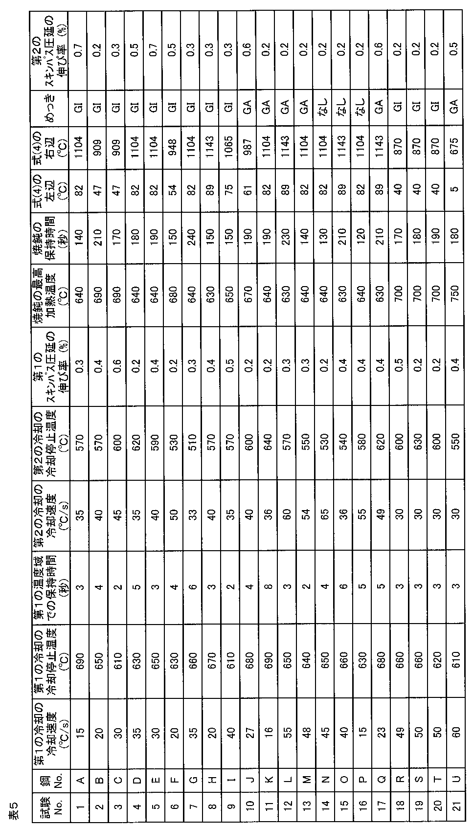

まず、鋼板から採取した試料をナイタールでエッチングした。エッチング後に光学顕微鏡を用いて板厚の1/4深さの位置において300μm×300μmの視野で得られた組織写真に対し、画像解析を行った。この画像解析により、フェライトの面積率、パーライトの面積率、並びにベイナイト及びマルテンサイトの合計面積率を得た。次いで、レペラ腐食した試料を用い、光学顕微鏡を用いて板厚の1/4深さの位置において300μm×300μmの視野で得られた組織写真に対し、画像解析を行った。この画像解析により、残留オーステナイト及びマルテンサイトの合計面積率を得た。さらに、圧延面法線方向から板厚の1/4深さまで面削した試料を用い、X線回折測定により残留オーステナイトの体積率を求めた。残留オーステナイトの体積率は、面積率と同等であるので、これを残留オーステナイトの面積率とした。そして、残留オーステナイト及びマルテンサイトの合計面積率から残留オーステナイトの面積率を減じることでマルテンサイトの面積率を得、ベイナイト及びマルテンサイトの合計面積率からマルテンサイトの面積率を減じることでベイナイトの面積率を得た。このようにして、フェライト、ベイナイト、マルテンサイト、残留オーステナイト及びパーライトのそれぞれの面積率を得た。 "Fraction, bainite, martensite, pearlite structure fraction (area ratio)"
First, a sample collected from a steel plate was etched with nital. After the etching, image analysis was performed on the structure photograph obtained with a field of view of 300 μm × 300 μm at a position of ¼ depth of the plate thickness using an optical microscope. By this image analysis, the area ratio of ferrite, the area ratio of pearlite, and the total area ratio of bainite and martensite were obtained. Next, image analysis was performed on a structural photograph obtained with a visual field of 300 μm × 300 μm at a position at a depth of ¼ of the plate thickness using an optical microscope, using a sample that had undergone repeller corrosion. By this image analysis, the total area ratio of retained austenite and martensite was obtained. Furthermore, the volume fraction of retained austenite was determined by X-ray diffraction measurement using a sample which was chamfered from the normal direction of the rolling surface to ¼ depth of the plate thickness. Since the volume ratio of retained austenite is equivalent to the area ratio, this was defined as the area ratio of retained austenite. Then, the area ratio of martensite is obtained by subtracting the area ratio of retained austenite from the total area ratio of retained austenite and martensite, and the area of bainite by subtracting the area ratio of martensite from the total area ratio of bainite and martensite. Got the rate. Thus, the area ratios of ferrite, bainite, martensite, retained austenite, and pearlite were obtained.
鋼板表面から板厚tの1/4深さ位置(1/4t部)の圧延方向垂直断面について、圧延方向に200μm、圧延面法線方向に100μmの領域を0.2μmの測定間隔でEBSD解析して結晶方位情報を得た。ここで、EBSD解析は、サーマル電界放射型走査電子顕微鏡(JEOL製JSM-7001F)とEBSD検出器(TSL製HIKARI検出器)で構成された装置を用い、200~300点/秒の解析速度で実施した。次に、得られた結晶方位情報に対して、方位差15°以上かつ円相当径で0.3μm以上の領域を結晶粒と定義し、結晶粒の粒内の平均方位差を計算し、粒内の方位差が5~14°である結晶粒の割合を求めた。上記で定義した結晶粒や粒内の平均方位差は、EBSD解析装置に付属のソフトウェア「OIM Analysis(登録商標)」を用いて算出した。 “Percentage of crystal grains with an orientation difference within the grain of 5 to 14 °”
EBSD analysis of a vertical cross section in the rolling direction at a 1/4 depth position (1 / 4t part) of the plate thickness t from the steel sheet surface at a measuring interval of 0.2 μm in a region of 200 μm in the rolling direction and 100 μm in the normal direction of the rolling surface. Thus, crystal orientation information was obtained. Here, the EBSD analysis is performed using an apparatus configured with a thermal field emission scanning electron microscope (JSMOL JSM-7001F) and an EBSD detector (TSL HIKARI detector) at an analysis speed of 200 to 300 points / second. Carried out. Next, with respect to the obtained crystal orientation information, a region having an orientation difference of 15 ° or more and an equivalent circle diameter of 0.3 μm or more is defined as a crystal grain, and an average orientation difference in the crystal grain is calculated. The ratio of crystal grains having an orientation difference of 5 to 14 ° was obtained. The crystal grains and the average orientation difference within the grains defined above were calculated using software “OIM Analysis (registered trademark)” attached to the EBSD analyzer.
特開2004-317203号公報に記載の方法に従って作製されたレプリカ試料を透過型電子顕微鏡にて観察することにより、析出物を観察した。視野は5000倍~100000倍の倍率で設定し、3視野以上から、10nm以下のTi(C,N)及びNb(C,N)の個数をカウントした。そして、電解前後での重量変化から電解重量を求め、比重7.8ton/m3から重量を体積に換算し、カウントした個数を体積で除することによって、合計析出物密度を算出した。 "Precipitate density"
Precipitates were observed by observing a replica sample produced according to the method described in JP-A-2004-317203 with a transmission electron microscope. The field of view was set at a magnification of 5000 to 100000 times, and the number of Ti (C, N) and Nb (C, N) of 10 nm or less from 3 or more fields was counted. Then, a electrolyte weight from weight change before and after electrolysis, in terms of the volume weight specific gravity 7.8ton / m 3, by dividing the volume of the counted number, to calculate the total precipitate density.
CAMP-ISIJ Vol.17(2004)p396に記載の「X線回折を利用した転位密度の評価方法」に準じて転位密度を測定し、(110)、(211)、(220)の半価幅から平均転位密度を算出した。 "Dislocation density"
CAMP-ISIJ Vol. 17 (2004) p396, dislocation density was measured according to “Method of evaluating dislocation density using X-ray diffraction”, and the average dislocation density was calculated from the half-value widths of (110), (211), and (220). Calculated.
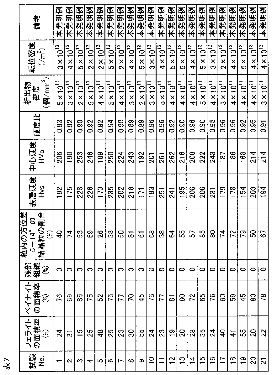

伸び[%]≧30-0.02×引張強度[MPa]・・・(6) In the tensile test, a JIS No. 5 tensile test piece was taken from a direction perpendicular to the rolling direction, and the test was performed according to JISZ2241. The elongation range corresponding to the strength level of the tensile strength was determined by the following formula (6), and the elongation (EL) was evaluated. Specifically, the acceptable range of elongation was set to a range equal to or larger than the value on the right side of the following formula (6) in consideration of the balance with tensile strength.
Elongation [%] ≧ 30-0.02 × Tensile strength [MPa] (6)


Claims (9)
- 質量%で、
C:0.008~0.150%、
Si:0.01~1.70%、
Mn:0.60~2.50%、
Al:0.010~0.60%、
Ti:0~0.200%、
Nb:0~0.200%、
Ti+Nb:0.015~0.200%、
Cr:0~1.0%、
B:0~0.10%、
Mo:0~1.0%、
Cu:0~2.0%、
Ni:0~2.0%、
Mg:0~0.05%、
REM:0~0.05%、
Ca:0~0.05%、
Zr:0~0.05%、
P:0.05%以下、
S:0.0200%以下、
N:0.0060%以下、かつ
残部:Fe及び不純物、
で表される化学組成を有し、
面積率で、
フェライト:5~60%、かつ
ベイナイト:40~95%、
で表される組織を有し、
方位差が15°以上の粒界によって囲まれ、かつ円相当径が0.3μm以上である領域を結晶粒と定義した場合に、粒内方位差が5~14°である結晶粒の全結晶粒に占める割合が面積率で20~100%であり、
円相当直径が10nm以下のTi(C,N)及びNb(C,N)の析出物密度が1010個/mm3以上であり、
表面から深さ20μmにおける硬度(Hvs)と、板厚中心の硬度(Hvc)との比(Hvs/Hvc)が、0.85以上であることを特徴とする鋼板。 % By mass
C: 0.008 to 0.150%,
Si: 0.01 to 1.70%,
Mn: 0.60 to 2.50%,
Al: 0.010 to 0.60%,
Ti: 0 to 0.200%,
Nb: 0 to 0.200%,
Ti + Nb: 0.015 to 0.200%,
Cr: 0 to 1.0%,
B: 0 to 0.10%,
Mo: 0 to 1.0%,
Cu: 0 to 2.0%,
Ni: 0 to 2.0%,
Mg: 0 to 0.05%,
REM: 0 to 0.05%,
Ca: 0 to 0.05%,
Zr: 0 to 0.05%,
P: 0.05% or less,
S: 0.0200% or less,
N: 0.0060% or less, and the balance: Fe and impurities,
Having a chemical composition represented by
In area ratio,
Ferrite: 5-60%, and bainite: 40-95%,
Having an organization represented by
When a region surrounded by a grain boundary with an orientation difference of 15 ° or more and an equivalent circle diameter of 0.3 μm or more is defined as a crystal grain, all crystals of the crystal grain with an in-grain orientation difference of 5 to 14 ° The proportion of grains in the area ratio is 20 to 100%,
The precipitate density of Ti (C, N) and Nb (C, N) having an equivalent circle diameter of 10 nm or less is 10 10 pieces / mm 3 or more,
A steel sheet, characterized in that the ratio (Hvs / Hvc) of the hardness (Hvs) at a depth of 20 μm from the surface to the hardness (Hvc) at the center of the plate thickness is 0.85 or more. - 平均転位密度が1×10¹⁴m-2以下であることを特徴とする請求項1に記載の鋼板。 The steel sheet according to claim 1, wherein the average dislocation density is 1 × 10 14 m −2 or less.
- 引張強度が480MPa以上であり、
前記引張強度と降伏強度との比が0.80以上であり、
前記引張強度と鞍型伸びフランジ試験における限界成形高さとの積が19500mm・MPa以上であり、
疲労強度比が0.45以上であることを特徴とする請求項1又は2に記載の鋼板。 The tensile strength is 480 MPa or more,
The ratio of the tensile strength and yield strength is 0.80 or more,
The product of the tensile strength and the limit molding height in the vertical stretch flange test is 19500 mm · MPa or more,
The steel sheet according to claim 1 or 2, wherein the fatigue strength ratio is 0.45 or more. - 前記化学成分が、質量%で、
Cr:0.05~1.0%、及び
B:0.0005~0.10%、
からなる群から選択される1種以上を含むことを特徴とする請求項1乃至3のいずれか1項に記載の鋼板。 The chemical component is mass%,
Cr: 0.05-1.0%, and B: 0.0005-0.10%,
The steel sheet according to any one of claims 1 to 3, comprising at least one selected from the group consisting of: - 前記化学成分が、質量%で、
Mo:0.01~1.0%、
Cu:0.01~2.0%、及び
Ni:0.01%~2.0%、
からなる群から選択される1種以上を含むことを特徴とする請求項1乃至4のいずれか1項に記載の鋼板。 The chemical component is mass%,
Mo: 0.01 to 1.0%,
Cu: 0.01 to 2.0%, and Ni: 0.01% to 2.0%,
The steel sheet according to any one of claims 1 to 4, comprising at least one selected from the group consisting of: - 前記化学成分が、質量%で、
Ca:0.0001~0.05%、
Mg:0.0001~0.05%、
Zr:0.0001~0.05%、及び
REM:0.0001~0.05%、
からなる群から選択される1種以上を含むことを特徴とする請求項1乃至5のいずれか1項に記載の鋼板。 The chemical component is mass%,
Ca: 0.0001 to 0.05%,
Mg: 0.0001 to 0.05%,
Zr: 0.0001 to 0.05%, and REM: 0.0001 to 0.05%,
The steel sheet according to any one of claims 1 to 5, comprising at least one selected from the group consisting of: - 請求項1乃至6のいずれか1項に記載の鋼板の表面に、めっき層が形成されていることを特徴とするめっき鋼板。 A plated steel sheet, wherein a plated layer is formed on the surface of the steel sheet according to any one of claims 1 to 6.
- 前記めっき層が、溶融亜鉛めっき層であることを特徴とする請求項7に記載のめっき鋼板。 The plated steel sheet according to claim 7, wherein the plated layer is a hot dip galvanized layer.
- 前記めっき層が、合金化溶融亜鉛めっき層であることを特徴とする請求項7に記載のめっき鋼板。 The plated steel sheet according to claim 7, wherein the plated layer is an alloyed hot-dip galvanized layer.
Priority Applications (8)
| Application Number | Priority Date | Filing Date | Title |
|---|---|---|---|
| BR112019001331A BR112019001331B8 (en) | 2016-08-05 | 2017-08-04 | Steel sheet |
| EP17837114.2A EP3495527A4 (en) | 2016-08-05 | 2017-08-04 | Steel sheet and plated steel sheet |
| MX2018016223A MX2018016223A (en) | 2016-08-05 | 2017-08-04 | Steel sheet and plated steel sheet. |
| JP2017562103A JP6354916B2 (en) | 2016-08-05 | 2017-08-04 | Steel plate and plated steel plate |
| CN201780046243.0A CN109477184B (en) | 2016-08-05 | 2017-08-04 | Steel sheet and plated steel sheet |
| KR1020197000428A KR102220940B1 (en) | 2016-08-05 | 2017-08-04 | Steel plate and plated steel plate |
| CN202110900748.7A CN113637923B (en) | 2016-08-05 | 2017-08-04 | Steel sheet and plated steel sheet |
| US16/314,945 US11649531B2 (en) | 2016-08-05 | 2017-08-04 | Steel sheet and plated steel sheet |
Applications Claiming Priority (2)
| Application Number | Priority Date | Filing Date | Title |
|---|---|---|---|
| JP2016-155101 | 2016-08-05 | ||
| JP2016155101 | 2016-08-05 |
Publications (1)
| Publication Number | Publication Date |
|---|---|
| WO2018026013A1 true WO2018026013A1 (en) | 2018-02-08 |
Family
ID=61072963
Family Applications (1)
| Application Number | Title | Priority Date | Filing Date |
|---|---|---|---|
| PCT/JP2017/028472 WO2018026013A1 (en) | 2016-08-05 | 2017-08-04 | Steel sheet and plated steel sheet |
Country Status (9)
| Country | Link |
|---|---|
| US (1) | US11649531B2 (en) |
| EP (1) | EP3495527A4 (en) |
| JP (1) | JP6354916B2 (en) |
| KR (1) | KR102220940B1 (en) |
| CN (2) | CN109477184B (en) |
| BR (1) | BR112019001331B8 (en) |
| MX (1) | MX2018016223A (en) |
| TW (1) | TWI629368B (en) |
| WO (1) | WO2018026013A1 (en) |
Cited By (5)
| Publication number | Priority date | Publication date | Assignee | Title |
|---|---|---|---|---|
| WO2020196311A1 (en) | 2019-03-22 | 2020-10-01 | 日本製鉄株式会社 | High-strength steel plate and method for manufacturing same |
| WO2020196326A1 (en) | 2019-03-22 | 2020-10-01 | 日本製鉄株式会社 | High-strength steel sheet and method for manufacturing same |
| WO2021131876A1 (en) | 2019-12-23 | 2021-07-01 | 日本製鉄株式会社 | Hot-rolled steel sheet |
| WO2023002910A1 (en) * | 2021-07-21 | 2023-01-26 | 日本製鉄株式会社 | Cold-rolled steel sheet and manufacturing method thereof |
| KR102658165B1 (en) | 2019-03-22 | 2024-04-19 | 닛폰세이테츠 가부시키가이샤 | High-strength steel plate and its manufacturing method |
Families Citing this family (11)
| Publication number | Priority date | Publication date | Assignee | Title |
|---|---|---|---|---|
| WO2016132549A1 (en) | 2015-02-20 | 2016-08-25 | 新日鐵住金株式会社 | Hot-rolled steel sheet |
| MX2017008622A (en) * | 2015-02-20 | 2017-11-15 | Nippon Steel & Sumitomo Metal Corp | Hot-rolled steel sheet. |
| CN107406929B (en) | 2015-02-25 | 2019-01-04 | 新日铁住金株式会社 | Hot rolled steel plate |
| WO2016135898A1 (en) | 2015-02-25 | 2016-09-01 | 新日鐵住金株式会社 | Hot-rolled steel sheet or plate |
| WO2018026014A1 (en) * | 2016-08-05 | 2018-02-08 | 新日鐵住金株式会社 | Steel sheet and plated steel sheet |
| MX2019000051A (en) * | 2016-08-05 | 2019-04-01 | Nippon Steel & Sumitomo Metal Corp | Steel sheet and plated steel sheet. |
| EP3495530A4 (en) * | 2016-08-05 | 2020-01-08 | Nippon Steel Corporation | Steel sheet and plated steel sheet |
| CN112575276A (en) * | 2020-12-03 | 2021-03-30 | 攀钢集团研究院有限公司 | Hot-dip zinc-aluminum-magnesium alloy coated steel plate for ultra-deep drawing and preparation method thereof |
| DE102021104584A1 (en) * | 2021-02-25 | 2022-08-25 | Salzgitter Flachstahl Gmbh | High-strength, hot-rolled flat steel product with high local cold workability and a method for producing such a flat steel product |
| CN116288024A (en) * | 2023-02-28 | 2023-06-23 | 马鞍山钢铁股份有限公司 | High-strength hot-base galvanized steel sheet with good forming performance and manufacturing method thereof |
| CN116288025A (en) * | 2023-02-28 | 2023-06-23 | 马鞍山钢铁股份有限公司 | High-strength structural-grade coated steel plate for photovoltaic and manufacturing method thereof |
Citations (5)
| Publication number | Priority date | Publication date | Assignee | Title |
|---|---|---|---|---|
| WO2008056812A1 (en) * | 2006-11-07 | 2008-05-15 | Nippon Steel Corporation | High young's modulus steel plate and process for production thereof |
| JP2009019265A (en) * | 2007-06-12 | 2009-01-29 | Nippon Steel Corp | High young's modulus steel sheet excellent in hole expansion property and its production method |
| JP2009191360A (en) * | 2008-01-17 | 2009-08-27 | Jfe Steel Corp | High strength steel sheet, and method for producing the same |
| WO2010137317A1 (en) * | 2009-05-27 | 2010-12-02 | 新日本製鐵株式会社 | High-strength steel sheet, hot-dipped steel sheet, and alloy hot-dipped steel sheet that have excellent fatigue, elongation, and collision characteristics, and manufacturing method for said steel sheets |
| WO2014014120A1 (en) * | 2012-07-20 | 2014-01-23 | 新日鐵住金株式会社 | Steel material |
Family Cites Families (32)
| Publication number | Priority date | Publication date | Assignee | Title |
|---|---|---|---|---|
| JP4062118B2 (en) * | 2002-03-22 | 2008-03-19 | Jfeスチール株式会社 | High-tensile hot-rolled steel sheet with excellent stretch characteristics and stretch flange characteristics and manufacturing method thereof |
| JP2005256115A (en) | 2004-03-12 | 2005-09-22 | Nippon Steel Corp | High strength hot rolled steel sheet having excellent stretch flange formability and fatigue property |
| JP4575893B2 (en) * | 2006-03-20 | 2010-11-04 | 新日本製鐵株式会社 | High strength steel plate with excellent balance of strength and ductility |
| JP5194858B2 (en) | 2008-02-08 | 2013-05-08 | Jfeスチール株式会社 | High strength hot rolled steel sheet and method for producing the same |
| JP5172391B2 (en) * | 2008-03-03 | 2013-03-27 | 株式会社神戸製鋼所 | Steel sheet with excellent toughness and uniform elongation of weld heat affected zone |
| JP5438302B2 (en) * | 2008-10-30 | 2014-03-12 | 株式会社神戸製鋼所 | High yield ratio high strength hot dip galvanized steel sheet or alloyed hot dip galvanized steel sheet with excellent workability and manufacturing method thereof |
| JP5423191B2 (en) | 2009-07-10 | 2014-02-19 | Jfeスチール株式会社 | High strength steel plate and manufacturing method thereof |
| JP5482204B2 (en) | 2010-01-05 | 2014-05-07 | Jfeスチール株式会社 | High strength hot rolled steel sheet and method for producing the same |
| US9273370B2 (en) | 2010-07-28 | 2016-03-01 | Nippon Steel & Sumitomo Metal Corporation | Hot-rolled steel sheet, cold-rolled steel sheet, galvanized steel sheet, and methods of manufacturing the same |
| CN103249853B (en) * | 2010-10-18 | 2015-05-20 | 新日铁住金株式会社 | Hot-rolled steel sheet, cold-olled steel sheet, and plated steel sheet each having exellent uniform ductility and local ductility in high-speed deformation |
| EP2489748B1 (en) * | 2011-02-18 | 2017-12-13 | ThyssenKrupp Steel Europe AG | Hot-rolled steel surface product produced from a complex phase steel and method for the manufacture |
| ES2632439T3 (en) * | 2011-04-13 | 2017-09-13 | Nippon Steel & Sumitomo Metal Corporation | Hot rolled steel sheet and its manufacturing method |
| EP2716783B1 (en) * | 2011-05-25 | 2018-08-15 | Nippon Steel & Sumitomo Metal Corporation | Hot-rolled steel sheet and process for producing same |
| CA2868956C (en) * | 2012-03-30 | 2020-04-14 | Kabushiki Kaisha Kobe Seiko Sho(Kobe Steel, Ltd.) | Hot-dip galvanized steel sheet for stamping having excellent cold workability, die hardenability, and surface quality, and producing method thereof |
| JP5720612B2 (en) | 2012-03-30 | 2015-05-20 | 新日鐵住金株式会社 | High strength hot rolled steel sheet excellent in formability and low temperature toughness and method for producing the same |
| TWI463018B (en) | 2012-04-06 | 2014-12-01 | Nippon Steel & Sumitomo Metal Corp | High strength steel plate with excellent crack arrest property |
| KR101706441B1 (en) | 2012-04-26 | 2017-02-13 | 제이에프이 스틸 가부시키가이샤 | High strength hot-rolled steel sheet having excellent ductility, stretch flangeability and uniformity and method for manufacturing the same |
| BR112014031739B1 (en) | 2012-06-26 | 2019-05-28 | Nippon Steel & Sumitomo Metal Corporation | HIGH-RESISTANCE HOT LAMINATED STEEL SHEET AND SAME PRODUCTION METHOD |
| JP5825225B2 (en) | 2012-08-20 | 2015-12-02 | 新日鐵住金株式会社 | Manufacturing method of hot-rolled steel sheet |
| MX2015014436A (en) * | 2013-04-15 | 2016-02-03 | Jfe Steel Corp | High-strength hot-rolled steel sheet and method for manufacturing same. |
| JP6194951B2 (en) * | 2013-04-15 | 2017-09-13 | 新日鐵住金株式会社 | Hot rolled steel sheet |
| JP6241274B2 (en) | 2013-12-26 | 2017-12-06 | 新日鐵住金株式会社 | Manufacturing method of hot-rolled steel sheet |
| JP6131872B2 (en) * | 2014-02-05 | 2017-05-24 | Jfeスチール株式会社 | High strength thin steel sheet and method for producing the same |
| CA2944863A1 (en) | 2014-04-23 | 2015-10-29 | Nippon Steel & Sumitomo Metal Corporation | Hot-rolled steel sheet for tailored rolled blank, tailored rolled blank, and methods for producing these |
| WO2016013145A1 (en) * | 2014-07-25 | 2016-01-28 | Jfeスチール株式会社 | High-strength hot-dip zinc-coated steel sheet and method for producing same |
| JP6390273B2 (en) | 2014-08-29 | 2018-09-19 | 新日鐵住金株式会社 | Manufacturing method of hot-rolled steel sheet |
| WO2016132549A1 (en) * | 2015-02-20 | 2016-08-25 | 新日鐵住金株式会社 | Hot-rolled steel sheet |
| MX2017008622A (en) * | 2015-02-20 | 2017-11-15 | Nippon Steel & Sumitomo Metal Corp | Hot-rolled steel sheet. |
| CN107406929B (en) * | 2015-02-25 | 2019-01-04 | 新日铁住金株式会社 | Hot rolled steel plate |
| EP3495530A4 (en) * | 2016-08-05 | 2020-01-08 | Nippon Steel Corporation | Steel sheet and plated steel sheet |
| WO2018026014A1 (en) * | 2016-08-05 | 2018-02-08 | 新日鐵住金株式会社 | Steel sheet and plated steel sheet |
| MX2019000051A (en) * | 2016-08-05 | 2019-04-01 | Nippon Steel & Sumitomo Metal Corp | Steel sheet and plated steel sheet. |
-
2017
- 2017-08-04 WO PCT/JP2017/028472 patent/WO2018026013A1/en unknown
- 2017-08-04 CN CN201780046243.0A patent/CN109477184B/en active Active
- 2017-08-04 EP EP17837114.2A patent/EP3495527A4/en not_active Withdrawn
- 2017-08-04 TW TW106126480A patent/TWI629368B/en not_active IP Right Cessation
- 2017-08-04 US US16/314,945 patent/US11649531B2/en active Active
- 2017-08-04 BR BR112019001331A patent/BR112019001331B8/en active Search and Examination
- 2017-08-04 JP JP2017562103A patent/JP6354916B2/en active Active
- 2017-08-04 KR KR1020197000428A patent/KR102220940B1/en active IP Right Grant
- 2017-08-04 MX MX2018016223A patent/MX2018016223A/en unknown
- 2017-08-04 CN CN202110900748.7A patent/CN113637923B/en active Active
Patent Citations (5)
| Publication number | Priority date | Publication date | Assignee | Title |
|---|---|---|---|---|
| WO2008056812A1 (en) * | 2006-11-07 | 2008-05-15 | Nippon Steel Corporation | High young's modulus steel plate and process for production thereof |
| JP2009019265A (en) * | 2007-06-12 | 2009-01-29 | Nippon Steel Corp | High young's modulus steel sheet excellent in hole expansion property and its production method |
| JP2009191360A (en) * | 2008-01-17 | 2009-08-27 | Jfe Steel Corp | High strength steel sheet, and method for producing the same |
| WO2010137317A1 (en) * | 2009-05-27 | 2010-12-02 | 新日本製鐵株式会社 | High-strength steel sheet, hot-dipped steel sheet, and alloy hot-dipped steel sheet that have excellent fatigue, elongation, and collision characteristics, and manufacturing method for said steel sheets |
| WO2014014120A1 (en) * | 2012-07-20 | 2014-01-23 | 新日鐵住金株式会社 | Steel material |
Non-Patent Citations (1)
| Title |
|---|
| See also references of EP3495527A4 * |
Cited By (12)
| Publication number | Priority date | Publication date | Assignee | Title |
|---|---|---|---|---|
| WO2020196311A1 (en) | 2019-03-22 | 2020-10-01 | 日本製鉄株式会社 | High-strength steel plate and method for manufacturing same |
| WO2020196326A1 (en) | 2019-03-22 | 2020-10-01 | 日本製鉄株式会社 | High-strength steel sheet and method for manufacturing same |
| JPWO2020196326A1 (en) * | 2019-03-22 | 2020-10-01 | ||
| JPWO2020196311A1 (en) * | 2019-03-22 | 2020-10-01 | ||
| KR20210119500A (en) | 2019-03-22 | 2021-10-05 | 닛폰세이테츠 가부시키가이샤 | High-strength steel sheet and its manufacturing method |
| KR20210125056A (en) | 2019-03-22 | 2021-10-15 | 닛폰세이테츠 가부시키가이샤 | High-strength steel sheet and its manufacturing method |
| JP7136335B2 (en) | 2019-03-22 | 2022-09-13 | 日本製鉄株式会社 | High-strength steel plate and its manufacturing method |
| JP7136336B2 (en) | 2019-03-22 | 2022-09-13 | 日本製鉄株式会社 | High-strength steel plate and its manufacturing method |
| KR102658165B1 (en) | 2019-03-22 | 2024-04-19 | 닛폰세이테츠 가부시키가이샤 | High-strength steel plate and its manufacturing method |
| WO2021131876A1 (en) | 2019-12-23 | 2021-07-01 | 日本製鉄株式会社 | Hot-rolled steel sheet |
| KR20220099570A (en) | 2019-12-23 | 2022-07-13 | 닛폰세이테츠 가부시키가이샤 | hot rolled steel |
| WO2023002910A1 (en) * | 2021-07-21 | 2023-01-26 | 日本製鉄株式会社 | Cold-rolled steel sheet and manufacturing method thereof |
Also Published As
| Publication number | Publication date |
|---|---|
| BR112019001331A2 (en) | 2019-05-07 |
| CN109477184A (en) | 2019-03-15 |
| JPWO2018026013A1 (en) | 2018-08-02 |
| TWI629368B (en) | 2018-07-11 |
| BR112019001331B8 (en) | 2023-10-10 |
| US20190309398A1 (en) | 2019-10-10 |
| KR20190015539A (en) | 2019-02-13 |
| CN109477184B (en) | 2021-10-08 |
| JP6354916B2 (en) | 2018-07-11 |
| MX2018016223A (en) | 2019-05-30 |
| TW201807214A (en) | 2018-03-01 |
| EP3495527A1 (en) | 2019-06-12 |
| US11649531B2 (en) | 2023-05-16 |
| BR112019001331B1 (en) | 2023-01-10 |
| EP3495527A4 (en) | 2019-12-25 |
| CN113637923A (en) | 2021-11-12 |
| CN113637923B (en) | 2022-08-30 |
| KR102220940B1 (en) | 2021-02-26 |
Similar Documents
| Publication | Publication Date | Title |
|---|---|---|
| JP6354916B2 (en) | Steel plate and plated steel plate | |
| US11236412B2 (en) | Steel sheet and plated steel sheet | |
| JP6358406B2 (en) | Steel plate and plated steel plate | |
| JP6365758B2 (en) | Hot rolled steel sheet | |
| KR101621639B1 (en) | Steel sheet, plated steel sheet, method for producing steel sheet, and method for producing plated steel sheet | |
| KR101597058B1 (en) | Cold-rolled steel sheet | |
| US11230755B2 (en) | Steel sheet and plated steel sheet | |
| KR20140033226A (en) | Method for producing cold-rolled steel sheet | |
| US20220056549A1 (en) | Steel sheet, member, and methods for producing them | |
| KR20210091790A (en) | grater | |
| KR102514898B1 (en) | Steel plate and its manufacturing method | |
| KR20140033227A (en) | Hot-dip plated cold-rolled steel sheet and process for producing same | |
| US20220090247A1 (en) | Steel sheet, member, and methods for producing them | |
| WO2020195605A1 (en) | Steel sheet, method for manufacturing same and plated steel sheet | |
| EP4223892A1 (en) | Steel sheet and steel sheet manufacturing method |
Legal Events
| Date | Code | Title | Description |
|---|---|---|---|
| ENP | Entry into the national phase |
Ref document number: 2017562103 Country of ref document: JP Kind code of ref document: A |
|
| 121 | Ep: the epo has been informed by wipo that ep was designated in this application |
Ref document number: 17837114 Country of ref document: EP Kind code of ref document: A1 |
|
| ENP | Entry into the national phase |
Ref document number: 20197000428 Country of ref document: KR Kind code of ref document: A |
|
| REG | Reference to national code |
Ref country code: BR Ref legal event code: B01A Ref document number: 112019001331 Country of ref document: BR |
|
| NENP | Non-entry into the national phase |
Ref country code: DE |
|
| ENP | Entry into the national phase |
Ref document number: 2017837114 Country of ref document: EP Effective date: 20190305 |
|
| ENP | Entry into the national phase |
Ref document number: 112019001331 Country of ref document: BR Kind code of ref document: A2 Effective date: 20190123 |