WO2018025844A1 - プレス成形用ガラス素材及びこれを用いた光学素子の製造方法 - Google Patents
プレス成形用ガラス素材及びこれを用いた光学素子の製造方法 Download PDFInfo
- Publication number
- WO2018025844A1 WO2018025844A1 PCT/JP2017/027844 JP2017027844W WO2018025844A1 WO 2018025844 A1 WO2018025844 A1 WO 2018025844A1 JP 2017027844 W JP2017027844 W JP 2017027844W WO 2018025844 A1 WO2018025844 A1 WO 2018025844A1
- Authority
- WO
- WIPO (PCT)
- Prior art keywords
- glass material
- radius
- curvature
- press molding
- press
- Prior art date
- Legal status (The legal status is an assumption and is not a legal conclusion. Google has not performed a legal analysis and makes no representation as to the accuracy of the status listed.)
- Ceased
Links
Images


Classifications
-
- C—CHEMISTRY; METALLURGY
- C03—GLASS; MINERAL OR SLAG WOOL
- C03B—MANUFACTURE, SHAPING, OR SUPPLEMENTARY PROCESSES
- C03B11/00—Pressing molten glass or performed glass reheated to equivalent low viscosity without blowing
-
- G—PHYSICS
- G02—OPTICS
- G02B—OPTICAL ELEMENTS, SYSTEMS OR APPARATUS
- G02B3/00—Simple or compound lenses
Definitions
- the present invention relates to a glass material for press molding and a method for producing an optical element using the same, and more specifically, a glass material for press molding in which at least the surface of a portion that becomes an optical functional surface is a free surface, and the same
- the present invention relates to a method for manufacturing an optical element using the.
- Patent Document 1 Conventionally, as a glass material for press molding used when manufacturing an optical element by press molding, for example, there is one described in Patent Document 1.
- the glass material for press molding described in Patent Document 1 receives a molten glass in a spherical receiving mold, and forms a glass material by holding the molten glass in a state where the molten glass is floated by jetting gas from the receiving surface. It is formed by so-called levitation molding.
- the glass material for press molding produced by this method has a lower surface formed by a curved surface having a curvature radius substantially the same as the curvature radius of the receiving mold, and the entire surface is formed by a smooth free surface.
- the field of application of lenses has been expanding, and along with this, diversification of the shape and size of lenses has progressed.
- a camera with a special projection method in which the center is telephoto and the periphery is wide-angle due to strong distortion.
- the aspherical lens used is required to have a complicated shape such as a thick wall and a large volume of the entire lens, but a small paraxial radius of curvature.
- An object of the present invention is to provide a press-molding glass material capable of press-molding an aspheric lens having a large volume and a complicated shape, and an optical element manufacturing method using the same.
- the glass material for press molding according to the present invention has a rotating body shape centered on the rotation axis, and at least the surface of a portion that becomes a pair of optical functional surfaces after molding is formed as a free surface.
- the first surface which is the surface of one of the optical functional surfaces in the direction of the rotation axis, is formed in a convex shape outward, and the center of the first surface is glass for press molding.
- a peripheral portion having a first radius of curvature that is smaller than the radius of a sphere having the same volume as the material and that is disposed adjacent to the central portion around the central portion is a second radius of curvature that is greater than the first radius of curvature. It is characterized by having.
- a glass material having a smooth surface can be obtained because the surface of the portion that becomes a pair of optical functional surfaces after molding of the glass material for press molding is a free surface.
- the center portion of the first surface of the press-molding glass material has a first radius of curvature smaller than the radius of a sphere having the same volume, and a second radius of curvature where the peripheral portion is larger than the first radius of curvature. Therefore, even if it is a glass material for press molding having a relatively large volume, the radius of curvature at the center is relatively small and a smoothly continuous overall shape can be obtained.
- the glass material for press molding is a glass material mainly used for precision press molding and refers to a so-called preform.
- the free surface refers to a surface when the molten glass is solidified without contacting other members such as a mold, and a surface on which a part of other members is transferred or polished. -Does not include surfaces that have been machined such as grinding.
- FIG. 1 is a diagram showing a cross-sectional shape including a rotation axis of a press-molding glass material 1 (hereinafter simply referred to as “glass material 1”) according to an embodiment of the present invention.
- the glass material 1 has at least a surface of an optical function surface formed as a free surface, has a rotating body shape centered on the rotation axis A, and has one surface (lower surface 6) in the direction of the rotation axis A.
- One surface (lower surface 6) has a first curvature radius R1 smaller than the radius of a sphere having the same volume as that of the glass material 1, and has one surface (lower surface 6).
- Peripheral portion 10 arranged adjacent to the periphery of has a second radius of curvature R2 that is larger than the first radius of curvature R1. Further, the curvature radius R7 of the other surface (upper surface 4) in the direction of the rotation axis A is larger than the curvature radius R1 of the lower surface 6.
- the optical functional surface means a region within an effective diameter in an optical element such as an optical lens.
- an optical element such as an optical lens.
- part used as the optical function surface in the glass raw material 1 changes variously with the shape and function of an optical element, at least the center of an optical axis (rotation axis A) and its peripheral region can become an optical function surface.
- the glass material 1 has at least a surface of a portion that becomes a pair of optical functional surfaces after press molding as a free surface, and has a rotating body shape centering on the rotation axis A, and rotates. 1 gradually increases from the bottom of FIG. 1 along the axis A, has a maximum diameter D1 at the maximum diameter position 2, and then gradually decreases again.
- the upper surface 4 above the maximum diameter position 2 is formed in a convex shape that curves outward, that is, upward.
- the lower surface 6 below the maximum diameter position 2 is formed in a convex shape that curves outward, that is, downward.
- S1 is a portion that becomes an optical functional surface on the upper surface 4 side
- S2 is a portion that becomes an optical functional surface on the lower surface 6 side.
- 4a and 6a have shown the surface of the site
- FIG. 2 is a diagram showing the relationship between the volume V of the glass material 1 and the radius of curvature R1 of the central portion 8 according to an embodiment of the present invention.
- the abscissa represents the curvature radius r
- the ordinate represents the volume V
- the curve C represents the relationship between the curvature radius (radius) of the sphere having the volume with respect to the volume.
- the radius of curvature R1 of the central portion 8 of the glass material 1 of the present embodiment is set so as to be located in a hatched region on the left side of the curve C.
- the radius of curvature R1 of the central portion 8 of the glass material 1 of the present embodiment is set to be smaller than the radius when a glass material having the same volume V as the glass material 1 is formed in a spherical shape.
- ⁇ indicates the relationship between the volume of the glass material and the radius of curvature in the example
- ⁇ indicates the relationship between the volume of the glass material and the radius of curvature in Comparative Example 1.
- ⁇ show the relationship between the volume of the glass material and the radius of curvature in Comparative Example 2.
- the glass material 1 is formed by pressing the glass material 1 to form the optical functional surface of the optical element when the optical element is formed (the first surface 6a and the first surface 6a).
- 2 surfaces 4a) are formed at least as free surfaces.
- the free surface refers to the surface when the molten glass is solidified without contacting other members such as a mold as described above, and the arithmetic average roughness Ra is 10 ⁇ 3 ⁇ m or less (1 nm or less). This is an extremely smooth surface.
- the arithmetic average roughness Ra is preferably 0.7 nm or less, and more preferably 0.5 nm or less, from the viewpoint of obtaining surface smoothness after the glass material 1 is press-molded.
- the glass material 1 has a rotating body shape centered on the rotation axis A, and one surface in the direction of the rotation axis A, that is, the lower surface 6 is formed in a convex shape outward, and the lower surface 6 has a center
- the portion 8 has a first radius of curvature R1 that is smaller than the radius of the sphere of the same volume, and the peripheral portion 10 disposed around the central portion 8 and adjacent to the central portion 8 is more than the first radius of curvature R1.
- the first radius of curvature R1 is, for example, 2 to 10 mm, preferably 3 to 8 mm, and more preferably 4 to 7 mm.
- the second radius of curvature R2 is, for example, 5 to 30 mm, but is not limited to this range.
- the ratio (L2 / L1) of the distance L2 to the point where the rotation axis A intersects is preferably set to 1.2 to 1.7. If the ratio of the distance L2 to the distance L1 is out of the above range, the stability of the glass material 1 when the glass material 1 is placed on a press molding die is deteriorated, and the rotation axis A of the glass material 1 is formed. It becomes difficult to align with the central axis of the mold.
- the thickness T of the rotation direction A direction of the glass raw material 1 shown in FIG. 1 is the sum total of the distance L1 and the distance L2.
- the lower limit of the ratio (L2 / L1) is preferably 1.2 or more from the viewpoint of suppressing the occurrence of gas traps during press molding.
- the glass material 1 is formed by so-called flotation molding, in which molten glass is received by a mold, gas is ejected from the receiving surface of the mold, and the molten glass is held in a floated state to mold the glass material. Accordingly, the entire surface of the glass material 1 is a free surface.
- the mold is made of, for example, a porous material.
- the shape of the mold is such that when the molten glass supplied to the mold is lifted and supported by the floating gas from the surface of the mold, the distance between the mold and the molten glass is the smallest at the periphery, and the center portion In this case, the distance between the mold and the molten glass is maximized.
- the shape of the mold is formed such that the pressure of the floating gas received on the surface of the molten glass in the mold is the highest in the peripheral portion and the lowest pressure distribution in the central portion.
- a plurality of molds are arranged at equal intervals on the circumference of the turntable, and the turntable is configured to be rotatable by a predetermined angle.
- a floating gas supply source is connected below the mold.
- the mold is heated with a heater so that the shape of the glass material 1 is distorted or cracked, and the glass material 1 does not stick when the glass material 1 comes into contact with the mold surface. The temperature is adjusted.
- the floating gas When the floating gas is supplied from below the mold configured as described above, the floating gas is ejected from the mold. When a predetermined amount of molten glass is supplied into the mold, the molten glass floats up from the mold due to the pressure of the floating gas. Oppositely, the lower surface 6 of the glass material 1 is formed, and is formed into a predetermined shape as shown in FIG. 1 as a whole.
- the material of the glass to be used is not particularly limited. For example, lanthanum borate glass mainly containing boric acid and rare earth oxide, phosphate glass mainly containing phosphate, fluorine and phosphorus. A fluorophosphate glass mainly composed of an acid salt, a borosilicate glass mainly composed of a borosilicate, and the like can be used.
- the molten glass moves on the turntable while being molded in the mold, and is cooled to a temperature range that does not deform even when an external force is applied to form the glass material 1. Thereafter, the glass material 1 is taken out of the mold and gradually cooled.
- the molded glass material 1 may be washed as necessary, and a carbon film may be formed on the entire surface as necessary. Such a carbon film improves the slip of the glass and improves the mold releasability of the molded optical element when the glass material 1 is press-molded into the optical element.
- the glass material 1 molded into the shape as shown in FIG. 1 is accommodated in a press molding mold, the mold is heated, the glass material 1 is softened and pressed to obtain an optical element having a predetermined shape.
- the radius of curvature R1 of the central portion 8 of the glass material 1 is formed to be smaller than the radius of curvature of the press-molding die at a position facing the central portion 8. Therefore, the softened glass material 1 comes into contact with the press-molding die from the central portion 8 on the lower surface 6, and the shape of the die is gradually transferred toward the outside and molded into a desired shape.
- FIG. 3 is a diagram illustrating an example of a cross-sectional shape of an optical element obtained by press molding a glass material for press molding according to an embodiment of the present invention.
- the outer peripheral portion of the molded body obtained by press-molding the glass material 1 has a surplus portion 26 as shown by a broken line.
- the portion where the surplus portion 26 is removed by centering is the optical element 16.
- the optical element 16 shown in FIG. 3 has a paraxial radius of curvature R3 that becomes the central portion 18 is relatively small (for example, a radius of curvature of 10 mm or less), and inward along the shaft 20 around the central portion 18 (FIG. 3).
- a curved portion 22 that is recessed upward is formed. Further, the surface opposite to the center portion 18 (the upper surface in FIG.
- the optical element 16 has a complicated shape as a whole, and is relatively thicker than the conventional one.
- part and range which perform a cold work differ according to the range of the optical function surface of an optical element. Therefore, the range and shape of the surplus portion 26 shown in FIG.
- the following effects can be obtained. Since the entire surface of the glass material 1 is formed with a free surface, a glass material 1 having a smooth surface is obtained. When an optical element is obtained by press-molding the glass material 1, an optical element having a good appearance and shape quality Can be obtained.
- the conventional glass material has a spherical shape or an elliptical shape with a radius of curvature larger than the radius of the sphere.
- the radius of curvature naturally increases accordingly. For this reason, for example, when trying to press-mold an aspheric lens with a complicated shape with a conventional glass material with a large volume, if the paraxial radius of curvature of the aspheric lens is small, the curvature radius of the glass material will be press-molded. It becomes larger than the radius of curvature of the metal mold for use, and gas accumulates between the glass material and the metal mold, so that an optical element having a good shape cannot be obtained.
- the curvature radius R1 of the center part 8 of the lower surface 6 of the glass material 1 is set smaller than the radius of the sphere having the same volume as the volume V of the glass material 1, comparison is made. Even in the case of the glass material 1 having a large target volume, the radius of curvature R1 of the central portion 8 can be formed small. Therefore, even in the case of molding a thick and complex optical element with a small paraxial radius of curvature, a molded product having a good shape can be obtained without causing a gas trap.
- the radius of curvature R2 of the peripheral portion 10 of the glass material 1 is formed larger than the radius of curvature R1 of the central portion 8, from the central portion 8 having a small radius of curvature R1 to the peripheral portion 10 having a larger radius of curvature R2.
- the transition region becomes smooth, and a continuous and smooth shape is obtained as a whole.
- the ratio of the distance L2 to the lower surface 6 with respect to the distance L1 from the maximum diameter position 2 to the upper surface 4 of the glass material 1 is appropriately set, so that the first curvature of the central portion is ensured while ensuring a relatively large volume.
- the radius R1 can be made relatively small, and even when the glass material 1 is press-molded into an aspheric lens having a complicated shape, an optical element with good quality can be obtained without causing a shape defect. be able to.
- the ratio of the distance L2 to the distance L1 is appropriately set, when the glass material 1 is placed on a press molding die, the glass material 1 can be stably placed in the die. it can. Therefore, the rotation axis A of the glass material 1 can be easily and surely aligned with the central axis of the mold, and an optical element having a good quality free from defects such as uneven thickness can be formed.
- a glass material 1 having a volume V of 547 mm 3 was produced using the above-described float forming.
- the radius of curvature R1 of the central portion 8 of the glass material 1 was 4.2 mm.
- This glass material 1 has the relationship between the volume and the radius of curvature shown by (2) in FIG. 2, which is in the hatched region on the left side of the curve C in FIG. Further, the entire surface of the glass material 1 is a free surface.
- Known methods were used for the method of supplying and cutting the molten glass, the floating conditions on the mold surface of the molten glass, and the like.
- the obtained glass material 1 was heated and softened, precision press-molded, and press-molded into an optical element 16 having a cross-sectional shape as shown in FIG.
- the curvature radius R3 of the central portion 18 of the convex surface of the obtained optical element 16 was 4.7 mm
- the curvature radius R4 of the concave surface 23 was 2.2 mm.
- the press-molding die was formed in a shape corresponding to the shape of the optical element 16.
- FIG. 4 is a view showing a cross-sectional shape of the glass material 24 of Comparative Example 1 of the present invention.
- a glass material 24 having a volume V of 250 mm 3 was produced using flotation molding.
- the radius of curvature R5 at the center of the glass material 24 was 4.5 mm.
- the glass material 24 has a relationship between the volume indicated by ⁇ in FIG. 2 and the radius of curvature, which is outside the hatched region on the right side of the curve C in FIG.
- the desired thickness and diameter were not particularly obtained, and the shape accuracy of the optical element was significantly deteriorated as compared with the Examples.
- Comparative Example 2 of the present invention will be described.
- a spherical glass material 24 having a volume of 550 mm 3 was produced by cold working.
- the radius of the obtained spherical glass material was 5.1 mm.
- This glass material has a relationship between the volume and the radius of curvature indicated by ⁇ in FIG. 2, which is on the curve C in FIG.
- a gas trap was generated in the central portion 18 of the optical element 16.
Landscapes
- Physics & Mathematics (AREA)
- Engineering & Computer Science (AREA)
- Chemical & Material Sciences (AREA)
- General Physics & Mathematics (AREA)
- Optics & Photonics (AREA)
- Manufacturing & Machinery (AREA)
- Materials Engineering (AREA)
- Organic Chemistry (AREA)
- Re-Forming, After-Treatment, Cutting And Transporting Of Glass Products (AREA)
- Surface Treatment Of Glass (AREA)
Abstract
ガラス素材1は、少なくとも成形後に一対の光学機能面となる部位の表面が自由表面で形成されるとともに、回転軸Aを中心とする回転体形状を有し、回転軸A方向の下面6が外方に向かって凸状に形成され、下面6は、中心部8が、ガラス素材1と同じ体積の球の半径より小さい第1の曲率半径R1を有し、中心部8の周囲に中心部8に隣接して配置された周辺部10は、第1の曲率半径R1よりも大きい第2の曲率半径R2を有する。
Description
本発明は、プレス成形用ガラス素材及びこれを用いた光学素子の製造方法に関し、より具体的には、少なくとも光学機能面となる部位の表面が自由表面で形成されたプレス成形用ガラス素材及びこれを用いた光学素子の製造方法に関する。
従来、光学素子をプレス成形で製造する際に使用するプレス成形用ガラス素材としては、例えば特許文献1に記載されるようなものがある。この特許文献1に記載のプレス成形用ガラス素材は、熔融ガラスを球面状の受け型に受け、受け面からガスを噴出して熔融ガラスを浮上させた状態で保持してガラス素材を成形する、いわゆる浮上成形で形成される。このため、この方法で製造されたプレス成形用ガラス素材は、受け型の曲率半径とほぼ同じ曲率半径の曲面で形成される下面を有するとともに、全面が滑らかな自由表面で形成される。
ところで近年では、レンズの適用分野が広がってきており、これに伴ってレンズの形状や大きさの多様化が進んでいる。例えば画像識別センシングの分野では、強い歪曲によって中心は望遠、周辺は広角という特殊な射影方式のカメラへの要求が高まっており、そのようなカメラの最も物点側に配置される第1レンズとして用いられる非球面レンズでは、厚肉でレンズ全体の体積が大きい一方で、近軸の曲率半径が小さい等、複雑な形状が求められている。
しかしながら、従来の形状のプレス成形用ガラス素材では、ガラス素材の体積を大きくすると下面(受け型に対向する面)の曲率半径も大きくなるが、このような従来の形状のプレス成形用ガラス素材を、近軸の曲率半径が小さい非球面レンズにプレス成形すると、プレス成形用ガラス素材とプレス用金型との間にガスが溜まってしまうガストラップが発生し、良好な形状品質の成形品を得ることができない。
本発明の目的は、体積が大きく形状が複雑な非球面レンズをプレス成形することができるプレス成形用ガラス素材及びこれを用いた光学素子の製造方法を提供することにある。
本発明の目的は、体積が大きく形状が複雑な非球面レンズをプレス成形することができるプレス成形用ガラス素材及びこれを用いた光学素子の製造方法を提供することにある。
上記の目的を達成するために、本発明のプレス成形用ガラス素材は、少なくとも成形後に一対の光学機能面となる部位の表面が自由表面で形成されるとともに、回転軸を中心とする回転体形状を有し、回転軸方向における一方の光学機能面となる部位の表面である第1の表面が外方に向かって凸状に形成され、第1の表面は、中心部が、プレス成形用ガラス素材と同じ体積の球の半径より小さい第1の曲率半径を有し、中心部の周囲に中心部に隣接して配置された周辺部は、第1の曲率半径よりも大きい第2の曲率半径を有する、ことを特徴としている。
このように構成された本発明においては、プレス成形用ガラス素材の少なくとも成形後に一対の光学機能面となる部位の表面が自由表面であるので滑らかな表面のガラス素材が得られる。また、プレス成形用ガラス素材の第1の表面の中心部が同じ体積の球の半径よりも小さい第1の曲率半径を有し、周辺部が第1の曲率半径よりも大きい第2の曲率半径を有するので、比較的大きな体積のプレス成形用ガラス素材であっても、中心部の曲率半径が比較的小さくなるとともに滑らかに連続した全体形状が得られる。したがって、プレス成形用ガラス素材を、例えば近軸の曲率半径が比較的小さい形状のレンズにプレス成形する場合であっても、中心部にガストラップが発生することなくプレス成形が行われるとともに、プレス成形する際の成形型の隅々までプレス成形用ガラス素材が行き渡って形状精度の高い光学素子が得られる。よって、厚肉で複雑な形状の非球面レンズを成形する場合であっても良好な品質の成形品が得られる。
以下、本発明の好ましい実施形態を添付図面を参照して説明する。
なお、本明細書において、プレス成形用ガラス素材とは、主に精密プレス成形に用いられるガラス素材であって、いわゆるプリフォームを指す。
また、本明細書において、自由表面とは、熔融ガラスが金型等の他の部材に接触することなく固化した際の表面を指すものとし、他の部材の一部が転写された面や研磨・研削等の機械加工が施された面は含まない。
なお、本明細書において、プレス成形用ガラス素材とは、主に精密プレス成形に用いられるガラス素材であって、いわゆるプリフォームを指す。
また、本明細書において、自由表面とは、熔融ガラスが金型等の他の部材に接触することなく固化した際の表面を指すものとし、他の部材の一部が転写された面や研磨・研削等の機械加工が施された面は含まない。
図1は、本発明の一実施形態に係るプレス成形用ガラス素材1(以下、単に「ガラス素材1」という)の回転軸を含む断面形状を示す図である。ガラス素材1は、少なくとも光学機能面となる部位の表面が自由表面で形成されるとともに、回転軸Aを中心とする回転体形状を有し、回転軸A方向の一方の面(下面6)が外方に向かって凸状に形成され、一方の面(下面6)は、中心部8が、ガラス素材1と同じ体積の球の半径より小さい第1の曲率半径R1を有し、中心部8の周囲に隣接して配置された周辺部10は、第1の曲率半径R1よりも大きい第2の曲率半径R2を有する。また、回転軸A方向の他方の面(上面4)の曲率半径R7は、下面6の曲率半径R1よりも大きくなっている。
なお、光学機能面とは、光学レンズ等の光学素子における有効径内の領域を意味するものである。ガラス素材1における光学機能面となる部位は、光学素子の形状や機能によって様々に異なるが、少なくとも光軸(回転軸A)の中心およびその周辺領域は光学機能面となりうる。
以下、本実施形態にかかるガラス素材1について、さらに詳細に説明する。図1に示すように、ガラス素材1は、少なくともプレス成形後に一対の光学機能面となる部位の表面が自由表面で形成されるとともに、回転軸Aを中心とする回転体形状を有し、回転軸Aに沿って図1の下から徐々に回転軸Aを中心とする直径が大きくなり、最大直径位置2において最大直径D1を有し、その後再び徐々に直径が小さくなる。このような形状により、最大直径位置2よりも上側の上面4は、外方、つまり上側に向かって湾曲する凸状に形成されている。また、最大直径位置2よりも下側の下面6は、外方、つまり下側に向かって湾曲する凸状に形成されている。なお、図1において、S1は上面4側の光学機能面となる部位であり、S2は下面6側の光学機能面となる部位である。また、4aおよび6aは、それぞれ光学機能面となる部位の表面を示しており、6aは第1の表面であり、4aは第2の表面である。この光学機能面となる部位の表面4a、6a以外の表面は、ガラス素材1をプレス成形した後に芯取加工により除去されたり、除去されない場合であっても光学的に機能しない面となるため、必ずしも自由表面でなくてもよい。なお、本実施形態では、ガラス素材1の全面が自由表面で形成されている。
下面6は、回転軸A近傍の中心部8と、中心部8の周囲に隣接して配置された周辺部10とを有する。
図2は、本発明の一実施形態に係るガラス素材1の体積Vと中心部8の曲率半径R1との関係を示す図である。この図2では、横軸を曲率半径rとし、縦軸を体積Vとし、体積に対する、その体積を有する球体の曲率半径(半径)の関係を曲線Cで示している。本実施形態のガラス素材1の中心部8の曲率半径R1は、この曲線Cよりも左側の、斜線を施した領域内に位置するように設定される。つまり、本実施形態のガラス素材1の中心部8の曲率半径R1は、ガラス素材1と同じ体積Vのガラス素材を球状に形成したときの半径よりも小さく設定されている。なお、図2中の■は実施例におけるガラス素材の体積と曲率半径との関係を示したものであり、○は比較例1におけるガラス素材の体積と曲率半径との関係を示したものであり、●は、比較例2におけるガラス素材の体積と曲率半径との関係を示したものである。これらについては後述する。
また、ガラス素材1においては、周辺部10の曲率半径R2は、中心部8の曲率半径R1よりも大きく設定されている。
図2は、本発明の一実施形態に係るガラス素材1の体積Vと中心部8の曲率半径R1との関係を示す図である。この図2では、横軸を曲率半径rとし、縦軸を体積Vとし、体積に対する、その体積を有する球体の曲率半径(半径)の関係を曲線Cで示している。本実施形態のガラス素材1の中心部8の曲率半径R1は、この曲線Cよりも左側の、斜線を施した領域内に位置するように設定される。つまり、本実施形態のガラス素材1の中心部8の曲率半径R1は、ガラス素材1と同じ体積Vのガラス素材を球状に形成したときの半径よりも小さく設定されている。なお、図2中の■は実施例におけるガラス素材の体積と曲率半径との関係を示したものであり、○は比較例1におけるガラス素材の体積と曲率半径との関係を示したものであり、●は、比較例2におけるガラス素材の体積と曲率半径との関係を示したものである。これらについては後述する。
また、ガラス素材1においては、周辺部10の曲率半径R2は、中心部8の曲率半径R1よりも大きく設定されている。
このように、ガラス素材1は、このガラス素材1をプレス成形して光学素子を成形したときに光学素子の光学機能面を形成することになるガラス素材1の表面(第1の表面6aおよび第2の表面4a)が、少なくとも自由表面で形成される。自由表面とは、上述のように熔融ガラスが金型等の他の部材に接触することなく固化した際の表面を指すものであり、算術平均粗さRaが10-3μm以下(1nm以下)の極めて平滑な面である。この算術平均粗さRaは、ガラス素材1をプレス成形した後の表面平滑性を得る観点から、0.7nm以下であることが好ましく、0.5nm以下であることが一層好ましい。
さらに、ガラス素材1は、回転軸Aを中心とする回転体形状を有し、回転軸A方向の一方の面、すなわち下面6が外方に向かって凸状に形成され、下面6は、中心部8が、同じ体積の球の半径より小さい第1の曲率半径R1を有し、中心部8の周囲に中心部8に隣接して配置された周辺部10は、第1の曲率半径R1よりも大きい第2の曲率半径R2を有する。
なお、第1の曲率半径R1は、例えば2~10mmであり、好ましくは3~8mmであり、より好ましくは4~7mmである。また、第2の曲率半径R2は、例えば5~30mmであるが、この範囲に限定されるものではない。
なお、第1の曲率半径R1は、例えば2~10mmであり、好ましくは3~8mmであり、より好ましくは4~7mmである。また、第2の曲率半径R2は、例えば5~30mmであるが、この範囲に限定されるものではない。
また、ガラス素材1において、最大直径位置2から上面4の最上端、すなわち上面4と回転軸Aとが交わる点までの距離L1に対する、最大直径位置2から下面6の最下端、すなわち下面6と回転軸Aとが交わる点までの距離L2の比(L2/L1)は、1.2~1.7に設定することが好ましい。この距離L1に対する距離L2の比が上記範囲外になると、ガラス素材1をプレス成形用の成形型に載置するときのガラス素材1の安定性が悪くなり、ガラス素材1の回転軸Aが成形型の中心軸に位置合わせすることが難しくなる。ガラス素材1の回転軸Aが成形型の中心軸からずれると、プレス成形して得られた光学素子は、偏肉が生じたものとなってしまう。
なお、図1に示すガラス素材1の回転軸A方向の厚みTは、距離L1と距離L2の総和である。
なお、図1に示すガラス素材1の回転軸A方向の厚みTは、距離L1と距離L2の総和である。
本発明者らは、距離L1に対する距離L2の比(L2/L1)とガラス素材の安定性との関係性について検証した結果、表1に示すような知見を得た。
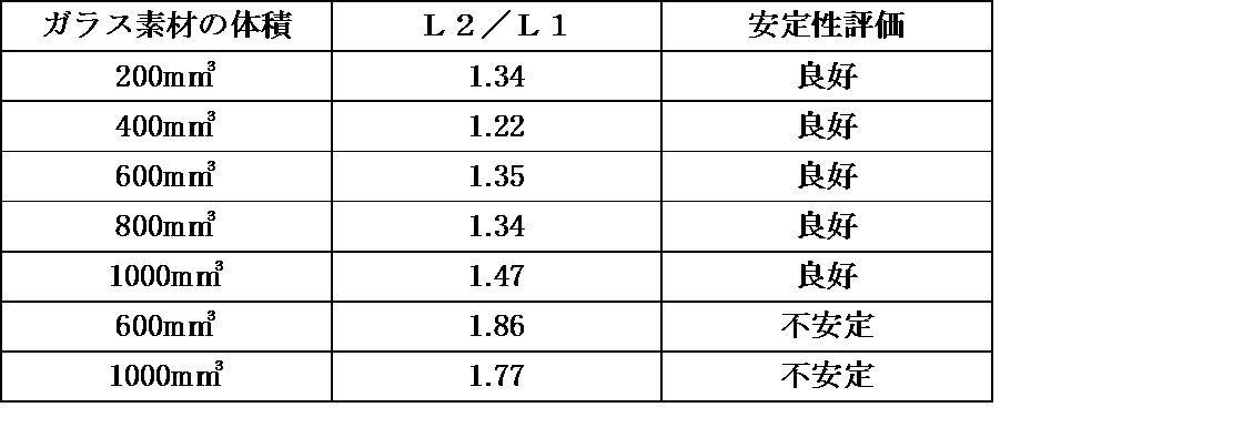
表1から明らかなように、距離L1に対する距離L2の比(L2/L1)が1.7以下であれば、ガラス素材の安定性は良好であるのに対して、上記比(L2/L1)が1.7を超えると不安定になることがわかる。
なお、上記比(L2/L1)の下限については、プレス成形時におけるガストラップの発生を抑制する観点から、1.2以上であることか望ましい。
次に、上記のようなガラス素材1の製造方法について説明する。
ガラス素材1は、熔融ガラスを金型に受け、金型の受け面からガスを噴出して熔融ガラスを浮上させた状態で保持してガラス素材を成形する、いわゆる浮上成形によって成形されている。したがって、ガラス素材1は、全面が自由表面で形成されている。
ガラス素材1は、熔融ガラスを金型に受け、金型の受け面からガスを噴出して熔融ガラスを浮上させた状態で保持してガラス素材を成形する、いわゆる浮上成形によって成形されている。したがって、ガラス素材1は、全面が自由表面で形成されている。
金型は、例えば多孔質材料で形成されている。金型の形状は、金型に供給された熔融ガラスが、浮上ガスによって金型の表面から浮上して支持されたとき、周辺部において金型と熔融ガラスとの距離が最も小さくなり、中心部において金型と熔融ガラスとの距離が最も大きくなるように形成される。また、金型の形状は、金型内で熔融ガラスの表面が受ける浮上ガスの圧力が、周辺部において最も高く、中心部において最も低い圧力分布となるように形成される。
金型は、ターンテーブルの円周上に等間隔に複数個配置され、ターンテーブルは所定角度ずつ回転可能に構成されている。金型の下方には浮上ガス供給源が接続されている。また、金型は、ガラス素材1の形状が歪んだり、割れを生じたり、金型の表面にガラス素材1が接触した場合にガラス素材1が貼り付いたりしないように、ヒーターで加熱され、適正な温度に調整される。
このように構成された金型の下方から浮上ガスを供給すると、浮上ガスが金型から噴出する。金型内に熔融ガラスを所定量供給すると、熔融ガラスは、浮上ガスの圧力で全体が金型から浮き上がり、浮上ガスの圧力、熔融ガラスの表面張力、及び自重のバランスによって、金型の内面に対向してガラス素材1の下面6が形成され、全体として図1のような所定の形状に成形される。
なお、使用されるガラスの材料としては、特に限定されないが、例えばホウ酸及び希土類酸化物を主成分とするホウ酸ランタン系ガラス、リン酸塩を主成分とするリン酸塩ガラス、フッ素及びリン酸塩を主成分とするフツリン酸塩ガラス、ホウケイ酸塩を主成分とするホウケイ酸塩系ガラス等を使用することができる。
なお、使用されるガラスの材料としては、特に限定されないが、例えばホウ酸及び希土類酸化物を主成分とするホウ酸ランタン系ガラス、リン酸塩を主成分とするリン酸塩ガラス、フッ素及びリン酸塩を主成分とするフツリン酸塩ガラス、ホウケイ酸塩を主成分とするホウケイ酸塩系ガラス等を使用することができる。
熔融ガラスは、金型内で成形されながらターンテーブル上で移動し、外力が加わっても変形しない温度域まで冷却され、ガラス素材1を形成する。その後、ガラス素材1を金型から取り出し、徐冷する。成形したガラス素材1を必要に応じて洗浄してもよいし、また必要に応じて全面にカーボン膜を形成してもよい。このようなカーボン膜は、ガラス素材1を光学素子にプレス成形する際に、ガラスの滑りをよくするとともに成形された光学素子の離型性を高める。
次に、ガラス素材1を用いて光学素子を製造する方法について説明する。図1のような形状に成形されたガラス素材1を、プレス成形用の金型内に収容し金型を加熱し、ガラス素材1を軟化させてプレスし、所定の形状の光学素子を得る。ここで、ガラス素材1の中心部8の曲率半径R1は、中心部8に対向する位置におけるプレス成形用の金型の曲率半径よりも小さく形成されている。よって、軟化したガラス素材1は、下面6において中心部8からプレス成形用の金型に接触し、徐々に外側に向かって金型の形状が転写され所望の形状に成形される。
図3は、本発明の一実施形態に係るプレス成形用ガラス素材をプレス成形して得られる光学素子の断面形状の一例を示す図である。ガラス素材1をプレス成形した成形体の外周部は、破線で示すような余肉部26を有するが、この余肉部26を芯取加工により除去した部分が光学素子16である。この図3に示す光学素子16は、中心部18となる近軸の曲率半径R3が比較的小さく(例えば曲率半径10mm以下)、中心部18の周囲には軸20に沿って内方(図3において上方)に凹んだ湾曲部22が形成されている。また、中心部18とは反対側の面(図3において上側の面)は、近軸の曲率半径R4を有し、内方(図3において下方)に凹んだ凹面23となっている。このように、光学素子16は、全体として複雑な形状を有し、従来より比較的肉厚に形成される。
なお、ガラス素材1をプレス成形した成形体に冷間加工を施して所定形状の光学素子を得る場合、冷間加工を施す部位や範囲は、光学素子の光学機能面の範囲に応じて異なる。したがって、図3に示した余肉部26の範囲や形状も様々に異なる。
なお、ガラス素材1をプレス成形した成形体に冷間加工を施して所定形状の光学素子を得る場合、冷間加工を施す部位や範囲は、光学素子の光学機能面の範囲に応じて異なる。したがって、図3に示した余肉部26の範囲や形状も様々に異なる。
本実施形態のガラス素材1によれば、次のような効果が得られる。
ガラス素材1の全面が自由表面で形成されるので、滑らかな表面のガラス素材1が得られ、このガラス素材1をプレス成形して光学素子を得たとき、良好な外観及び形状品質の光学素子を得ることができる。
ガラス素材1の全面が自由表面で形成されるので、滑らかな表面のガラス素材1が得られ、このガラス素材1をプレス成形して光学素子を得たとき、良好な外観及び形状品質の光学素子を得ることができる。
従来のガラス素材は、球形状を有するか、球の半径よりも大きな曲率半径の楕円形状を有しており、ガラス素材全体の体積を大きくするとそれに伴って曲率半径も当然大きくなる。このため、体積を大きくした従来のガラス素材で、例えば複雑な形状の非球面レンズをプレス成形しようとした場合、非球面レンズの近軸の曲率半径が小さいと、ガラス素材の曲率半径がプレス成形用の金型の曲率半径よりも大きくなってガラス素材と金型との間にガスが溜まってしまい、良好な形状の光学素子を得ることができない。
これに対して、本実施形態では、ガラス素材1の下面6の中心部8の曲率半径R1が、ガラス素材1の体積Vと同じ体積を有する球の半径よりも小さく設定されているので、比較的体積の大きいガラス素材1であっても、中心部8の曲率半径R1を小さく形成することができる。したがって、近軸の曲率半径が小さい肉厚で複雑な形状の光学素子を成形する場合であっても、ガストラップを生じることなく良好な形状の成形品を得ることができる。
これに対して、本実施形態では、ガラス素材1の下面6の中心部8の曲率半径R1が、ガラス素材1の体積Vと同じ体積を有する球の半径よりも小さく設定されているので、比較的体積の大きいガラス素材1であっても、中心部8の曲率半径R1を小さく形成することができる。したがって、近軸の曲率半径が小さい肉厚で複雑な形状の光学素子を成形する場合であっても、ガストラップを生じることなく良好な形状の成形品を得ることができる。
ガラス素材1の周辺部10の曲率半径R2が、中心部8の曲率半径R1よりも大きく形成されているので、小さな曲率半径R1を有する中心部8からより大きな曲率半径R2を有する周辺部10へ移行領域が滑らかとなり、全体として連続した滑らかな形状が得られる。
ガラス素材1の最大直径位置2から上面4までの距離L1に対する、下面6までの距離L2の比が適切に設定されているので、比較的大きな体積を確保しながら、中央部の第1の曲率半径R1を比較的小さくすることが可能になり、ガラス素材1を、複雑な形状の非球面レンズにプレス成形する場合であっても、形状不良を発生させることなく良好な品質の光学素子を得ることができる。
また、距離L1に対する距離L2の比が適切に設定されているので、ガラス素材1をプレス成形用の金型に載置した際、金型内にガラス素材1を安定して載置することができる。したがって、ガラス素材1の回転軸Aを金型の中心軸に容易且つ確実に位置合わせすることができ、偏肉等の不具合のない、良好な品質の光学素子を成形することができる。
また、距離L1に対する距離L2の比が適切に設定されているので、ガラス素材1をプレス成形用の金型に載置した際、金型内にガラス素材1を安定して載置することができる。したがって、ガラス素材1の回転軸Aを金型の中心軸に容易且つ確実に位置合わせすることができ、偏肉等の不具合のない、良好な品質の光学素子を成形することができる。
[実施例]
本発明の実施例について説明する。
上記浮上成形を用いて、体積Vが547mm3のガラス素材1を作製した。ガラス素材1の中心部8の曲率半径R1は、4.2mmとした。このガラス素材1は、図2において、■で示す体積と曲率半径との関係を有し、これは図2の曲線Cよりも左側の、斜線領域内にある。また、このガラス素材1は全面が自由表面である。
熔融ガラスの供給・切断方法、熔融ガラスの金型面上での浮上条件等は、公知の方法を用いた。
得られたガラス素材1を加熱して軟化させて精密プレス成形し、図3に示すような断面形状の光学素子16にプレス成形した。得られた光学素子16の凸面の中心部18の曲率半径R3は4.7mmであり、凹面23の曲率半径R4は、2.2mmであった。なお、プレス成形用金型は、光学素子16の形状に対応する形状に形成されていた。
ガラス素材1を加熱してプレス成形用金型で精密プレス成形した結果、所望の曲率半径R3,R4を維持しつつ、所望の肉厚及び径を有する光学素子16が再現性よく得られた。
本発明の実施例について説明する。
上記浮上成形を用いて、体積Vが547mm3のガラス素材1を作製した。ガラス素材1の中心部8の曲率半径R1は、4.2mmとした。このガラス素材1は、図2において、■で示す体積と曲率半径との関係を有し、これは図2の曲線Cよりも左側の、斜線領域内にある。また、このガラス素材1は全面が自由表面である。
熔融ガラスの供給・切断方法、熔融ガラスの金型面上での浮上条件等は、公知の方法を用いた。
得られたガラス素材1を加熱して軟化させて精密プレス成形し、図3に示すような断面形状の光学素子16にプレス成形した。得られた光学素子16の凸面の中心部18の曲率半径R3は4.7mmであり、凹面23の曲率半径R4は、2.2mmであった。なお、プレス成形用金型は、光学素子16の形状に対応する形状に形成されていた。
ガラス素材1を加熱してプレス成形用金型で精密プレス成形した結果、所望の曲率半径R3,R4を維持しつつ、所望の肉厚及び径を有する光学素子16が再現性よく得られた。
[比較例1]
次に、本発明の比較例1について説明する。
図4は、本発明の比較例1のガラス素材24の断面形状を示す図である。比較例1では、浮上成形を用いて、体積Vが250mm3のガラス素材24を作製した。ガラス素材24の中心部の曲率半径R5は、4.5mmとした。このガラス素材24は、図2において、○で示す体積と曲率半径との関係を有し、これは図2の曲線Cよりも右側の、斜線領域の外にある。
ガラス素材24を加熱してプレス成形用金型で精密プレス成形した結果、特に所望の肉厚及び径が得られず、実施例に比べて、光学素子の形状精度が著しく悪化していた。
次に、本発明の比較例1について説明する。
図4は、本発明の比較例1のガラス素材24の断面形状を示す図である。比較例1では、浮上成形を用いて、体積Vが250mm3のガラス素材24を作製した。ガラス素材24の中心部の曲率半径R5は、4.5mmとした。このガラス素材24は、図2において、○で示す体積と曲率半径との関係を有し、これは図2の曲線Cよりも右側の、斜線領域の外にある。
ガラス素材24を加熱してプレス成形用金型で精密プレス成形した結果、特に所望の肉厚及び径が得られず、実施例に比べて、光学素子の形状精度が著しく悪化していた。
[比較例2]
次に、本発明の比較例2について説明する。
比較例2では、体積550mm3の球状のガラス素材24を冷間加工で作製した。得られた球状のガラス素材の半径は、5.1mmであった。このガラス素材は、図2において、●で示す体積と曲率半径との関係を有し、これは図2の曲線C上にある。得られたガラス素材を、実施例と同じ精密プレス成形用金型で精密プレス成形したところ、光学素子16の中心部18にガストラップが発生した。これは、光学素子16の中心部18の曲率半径R3は4.7mmであるのに対して、ガラス素材の半径が5.1mmであるため、ガラス素材とプレス成形用金型との間にガスが溜まったためと考えられる。
次に、本発明の比較例2について説明する。
比較例2では、体積550mm3の球状のガラス素材24を冷間加工で作製した。得られた球状のガラス素材の半径は、5.1mmであった。このガラス素材は、図2において、●で示す体積と曲率半径との関係を有し、これは図2の曲線C上にある。得られたガラス素材を、実施例と同じ精密プレス成形用金型で精密プレス成形したところ、光学素子16の中心部18にガストラップが発生した。これは、光学素子16の中心部18の曲率半径R3は4.7mmであるのに対して、ガラス素材の半径が5.1mmであるため、ガラス素材とプレス成形用金型との間にガスが溜まったためと考えられる。
以上のように、本発明によるガラス素材1では、実施例のように良好な形状の光学素子が得られた。一方、比較例1及び2に記載した従来のガラス素子では、ガストラップが発生し、良好な形状の光学素子が得られなかった。
1 プレス成形用ガラス素材
4 上面
4a 光学機能面となる部位の表面(第2の表面)
6 下面
6a 光学機能面となる部位の表面(第1の表面)
8 中心部
10 周辺部
R1,R2 曲率半径
D1 最大直径
T 厚み
L1,L2 距離
S1,S2 光学機能面となる部位
4 上面
4a 光学機能面となる部位の表面(第2の表面)
6 下面
6a 光学機能面となる部位の表面(第1の表面)
8 中心部
10 周辺部
R1,R2 曲率半径
D1 最大直径
T 厚み
L1,L2 距離
S1,S2 光学機能面となる部位
Claims (5)
- プレス成形用ガラス素材において、
少なくとも成形後に一対の光学機能面となる部位の表面が自由表面で形成されるとともに、回転軸を中心とする回転体形状を有し、
前記回転軸方向における一方の前記光学機能面となる部位の表面である第1の表面が外方に向かって凸状に形成され、前記第1の表面は、中心部が、前記プレス成形用ガラス素材と同じ体積の球の半径より小さい第1の曲率半径を有し、
前記中心部の周囲に前記中心部に隣接して配置された周辺部は、前記第1の曲率半径よりも大きい第2の曲率半径を有する、
プレス成形用ガラス素材。 - 前記回転軸を中心とする前記プレス成形用ガラス素材の直径が最大となる位置から、前記第1の表面側の端部までの前記回転軸に沿った距離に対する、前記直径が最大となる位置から他方の前記光学機能面となる部位の表面である第2の表面側の端部までの前記回転軸に沿った距離の比は、1.2~1.7である、
請求項1に記載のプレス成形用ガラス素材。 - 前記自由表面の算術平均粗さRaは1nm以下である、請求項1または2に記載のプレス成形用ガラス素材。
- 前記第一の曲率半径は、2~10mmである、請求項1~3の何れか1項に記載のプレス成形用ガラス素材。
- 請求項1~4の何れか1項に記載のプレス成形用ガラス素材を加熱してプレス成形するプレス成形工程を備えている、光学素子の製造方法。
Priority Applications (2)
| Application Number | Priority Date | Filing Date | Title |
|---|---|---|---|
| JP2018531910A JP6976950B2 (ja) | 2016-08-01 | 2017-08-01 | プレス成形用ガラス素材及びこれを用いた光学素子の製造方法 |
| CN201780040003.XA CN109415236B (zh) | 2016-08-01 | 2017-08-01 | 模压成型用玻璃坯料和使用该玻璃坯料的光学元件的制造方法 |
Applications Claiming Priority (2)
| Application Number | Priority Date | Filing Date | Title |
|---|---|---|---|
| JP2016-151541 | 2016-08-01 | ||
| JP2016151541 | 2016-08-01 |
Publications (1)
| Publication Number | Publication Date |
|---|---|
| WO2018025844A1 true WO2018025844A1 (ja) | 2018-02-08 |
Family
ID=61073041
Family Applications (1)
| Application Number | Title | Priority Date | Filing Date |
|---|---|---|---|
| PCT/JP2017/027844 Ceased WO2018025844A1 (ja) | 2016-08-01 | 2017-08-01 | プレス成形用ガラス素材及びこれを用いた光学素子の製造方法 |
Country Status (3)
| Country | Link |
|---|---|
| JP (1) | JP6976950B2 (ja) |
| CN (1) | CN109415236B (ja) |
| WO (1) | WO2018025844A1 (ja) |
Citations (2)
| Publication number | Priority date | Publication date | Assignee | Title |
|---|---|---|---|---|
| JP2007099529A (ja) * | 2005-09-30 | 2007-04-19 | Hoya Corp | 精密プレス成形用プリフォームおよびその製造方法ならびに光学素子の製造方法 |
| JP2011068506A (ja) * | 2009-09-24 | 2011-04-07 | Ohara Inc | ガラス成形体の製造方法 |
Family Cites Families (3)
| Publication number | Priority date | Publication date | Assignee | Title |
|---|---|---|---|---|
| JP4460339B2 (ja) * | 2004-03-30 | 2010-05-12 | Hoya株式会社 | モールドプレス成形装置及び光学素子の製造方法 |
| CN101076501A (zh) * | 2004-12-13 | 2007-11-21 | 株式会社小原 | 光学元件预型体和光学元件 |
| JP2007197241A (ja) * | 2006-01-25 | 2007-08-09 | Konica Minolta Opto Inc | 光学ガラス素子の成形方法 |
-
2017
- 2017-08-01 JP JP2018531910A patent/JP6976950B2/ja active Active
- 2017-08-01 CN CN201780040003.XA patent/CN109415236B/zh active Active
- 2017-08-01 WO PCT/JP2017/027844 patent/WO2018025844A1/ja not_active Ceased
Patent Citations (2)
| Publication number | Priority date | Publication date | Assignee | Title |
|---|---|---|---|---|
| JP2007099529A (ja) * | 2005-09-30 | 2007-04-19 | Hoya Corp | 精密プレス成形用プリフォームおよびその製造方法ならびに光学素子の製造方法 |
| JP2011068506A (ja) * | 2009-09-24 | 2011-04-07 | Ohara Inc | ガラス成形体の製造方法 |
Also Published As
| Publication number | Publication date |
|---|---|
| CN109415236A (zh) | 2019-03-01 |
| JP6976950B2 (ja) | 2021-12-08 |
| JPWO2018025844A1 (ja) | 2019-07-18 |
| CN109415236B (zh) | 2022-08-09 |
Similar Documents
| Publication | Publication Date | Title |
|---|---|---|
| TWI710531B (zh) | 壓製成型用玻璃素材、壓製成型用玻璃素材之製造方法及光學元件之製造方法 | |
| KR101267117B1 (ko) | 성형품의 제조 방법, 유리 소재, 및 유리 소재와 성형형의면 형상 결정 방법 | |
| TW201111144A (en) | High sag optical lens and method for fast molding the same | |
| JPWO2014097830A1 (ja) | ガラス成形体の製造方法及び成形型 | |
| JP3714360B1 (ja) | 光学ガラス素子およびその製造方法 | |
| TW201339645A (zh) | 用於自動立體顯示器的玻璃圓柱透鏡 | |
| TWI499563B (zh) | Method for producing glass preform, and | |
| CN101250021B (zh) | 透镜坯和透镜的制造方法 | |
| KR101633874B1 (ko) | 비구면 렌즈의 성형금형 | |
| CN101386465A (zh) | 模造玻璃的模具 | |
| JP5828915B2 (ja) | モールドプレス成形用ガラスプリフォームの製造方法、及び、光学素子の製造方法 | |
| US20210129466A1 (en) | Optical element and method for manufacturing the same | |
| US7561355B2 (en) | Optical lens unit including lens barrel containing lens and method for producing optical lens unit | |
| JP6976950B2 (ja) | プレス成形用ガラス素材及びこれを用いた光学素子の製造方法 | |
| JP4318681B2 (ja) | 精密プレス成形用プリフォームおよびその製造方法ならびに光学素子の製造方法 | |
| CN101343140A (zh) | 模造玻璃镜片及其成型模具 | |
| JP3922834B2 (ja) | ガラス光学素子用成形型及び該成形型を用いたガラス光学素子の製造方法 | |
| JP2007091568A (ja) | ガラスレンズ、ガラスレンズの製造方法、及びモールドプレス成形型 | |
| JP2006001803A (ja) | モールドプレス成形型、光学素子の製造方法、及びモールドプレスレンズ | |
| JP2661449B2 (ja) | 非球面成形レンズの製造法 | |
| JP2007055870A (ja) | 光学素子成形型 | |
| JP2012532829A5 (ja) | 合成石英ガラスからなるメニスカスレンズおよびその製造法 | |
| JPH05301723A (ja) | 光学素子の成形方法 | |
| TWI374120B (en) | The forming device of molding glasses | |
| JP5430092B2 (ja) | 光学素子の成形方法 |
Legal Events
| Date | Code | Title | Description |
|---|---|---|---|
| ENP | Entry into the national phase |
Ref document number: 2018531910 Country of ref document: JP Kind code of ref document: A |
|
| 121 | Ep: the epo has been informed by wipo that ep was designated in this application |
Ref document number: 17836948 Country of ref document: EP Kind code of ref document: A1 |
|
| NENP | Non-entry into the national phase |
Ref country code: DE |
|
| 122 | Ep: pct application non-entry in european phase |
Ref document number: 17836948 Country of ref document: EP Kind code of ref document: A1 |