WO2018025665A1 - モータ制御回路、モータ制御装置、アクチュエータ及びステッピングモータの制御方法 - Google Patents
モータ制御回路、モータ制御装置、アクチュエータ及びステッピングモータの制御方法 Download PDFInfo
- Publication number
- WO2018025665A1 WO2018025665A1 PCT/JP2017/026467 JP2017026467W WO2018025665A1 WO 2018025665 A1 WO2018025665 A1 WO 2018025665A1 JP 2017026467 W JP2017026467 W JP 2017026467W WO 2018025665 A1 WO2018025665 A1 WO 2018025665A1
- Authority
- WO
- WIPO (PCT)
- Prior art keywords
- temperature
- speed
- motor control
- input voltage
- stepping motor
- Prior art date
- Legal status (The legal status is an assumption and is not a legal conclusion. Google has not performed a legal analysis and makes no representation as to the accuracy of the status listed.)
- Ceased
Links
Images



Classifications
-
- H—ELECTRICITY
- H02—GENERATION; CONVERSION OR DISTRIBUTION OF ELECTRIC POWER
- H02P—CONTROL OR REGULATION OF ELECTRIC MOTORS, ELECTRIC GENERATORS OR DYNAMO-ELECTRIC CONVERTERS; CONTROLLING TRANSFORMERS, REACTORS OR CHOKE COILS
- H02P8/00—Arrangements for controlling dynamo-electric motors rotating step by step
- H02P8/22—Control of step size; Intermediate stepping, e.g. microstepping
-
- H—ELECTRICITY
- H02—GENERATION; CONVERSION OR DISTRIBUTION OF ELECTRIC POWER
- H02P—CONTROL OR REGULATION OF ELECTRIC MOTORS, ELECTRIC GENERATORS OR DYNAMO-ELECTRIC CONVERTERS; CONTROLLING TRANSFORMERS, REACTORS OR CHOKE COILS
- H02P8/00—Arrangements for controlling dynamo-electric motors rotating step by step
- H02P8/14—Arrangements for controlling speed or speed and torque
-
- H—ELECTRICITY
- H02—GENERATION; CONVERSION OR DISTRIBUTION OF ELECTRIC POWER
- H02K—DYNAMO-ELECTRIC MACHINES
- H02K37/00—Motors with rotor rotating step by step and without interrupter or commutator driven by the rotor, e.g. stepping motors
- H02K37/10—Motors with rotor rotating step by step and without interrupter or commutator driven by the rotor, e.g. stepping motors of permanent magnet type
- H02K37/12—Motors with rotor rotating step by step and without interrupter or commutator driven by the rotor, e.g. stepping motors of permanent magnet type with stationary armatures and rotating magnets
-
- H—ELECTRICITY
- H02—GENERATION; CONVERSION OR DISTRIBUTION OF ELECTRIC POWER
- H02K—DYNAMO-ELECTRIC MACHINES
- H02K37/00—Motors with rotor rotating step by step and without interrupter or commutator driven by the rotor, e.g. stepping motors
- H02K37/24—Structural association with auxiliary mechanical devices
-
- H—ELECTRICITY
- H02—GENERATION; CONVERSION OR DISTRIBUTION OF ELECTRIC POWER
- H02P—CONTROL OR REGULATION OF ELECTRIC MOTORS, ELECTRIC GENERATORS OR DYNAMO-ELECTRIC CONVERTERS; CONTROLLING TRANSFORMERS, REACTORS OR CHOKE COILS
- H02P29/00—Arrangements for regulating or controlling electric motors, appropriate for both AC and DC motors
- H02P29/60—Controlling or determining the temperature of the motor or of the drive
-
- H—ELECTRICITY
- H02—GENERATION; CONVERSION OR DISTRIBUTION OF ELECTRIC POWER
- H02P—CONTROL OR REGULATION OF ELECTRIC MOTORS, ELECTRIC GENERATORS OR DYNAMO-ELECTRIC CONVERTERS; CONTROLLING TRANSFORMERS, REACTORS OR CHOKE COILS
- H02P8/00—Arrangements for controlling dynamo-electric motors rotating step by step
- H02P8/34—Monitoring operation
Definitions
- the present invention relates to a motor control circuit, a motor control device, an actuator, and a stepping motor control method, and more particularly, to a motor control circuit, a motor control device, an actuator, and a stepping motor control method used for an actuator using a stepping motor.
- Stepping motors have various features such as easy control, and are widely used for various actuators (for example, see Patent Document 1 below).
- the required torque and drive speed specifications are appropriately set depending on the application of the actuator.
- the temperature and the input voltage input to the motor control device may fluctuate.
- the present invention has been made in order to solve such problems, and it is possible to provide a motor control circuit, a motor control device, an actuator, and a stepping motor that can drive a motor while ensuring a driving torque in a wide range of usage environments. It aims to provide a control method.
- a motor control circuit used in a motor control device that drives a stepping motor includes an input voltage measurement unit that measures an input voltage input to the motor control device, and a temperature.
- a speed setting unit that sets a target value for the stepping motor drive speed based on the temperature measurement unit to be measured, the measurement result of the input voltage measurement unit, and the measurement result of the temperature measurement unit, and the drive speed set by the speed setting unit
- a speed control unit that controls the driving speed according to the target value, and the speed setting unit is set in advance for each of the plurality of partial regions that are divided in a matrix by a threshold value related to the input voltage and a threshold value related to the temperature.
- the target value is set based on the setting value of the driving speed.
- the speed setting unit is based on setting values set in advance for each of the nine partial regions that are divided into a matrix of 3 rows and 3 columns with two threshold values related to input voltage and two threshold values related to temperature. Set the target value.
- the set value is larger than the low voltage and higher than the medium voltage for each range of low voltage, medium voltage, and high voltage that are divided by two thresholds with respect to the input voltage. Is set to be larger, and for each range of low temperature, medium temperature, and high temperature divided by two thresholds, the temperature is higher than the medium temperature, It is set so that the low temperature is larger than the high temperature.
- a motor control device includes the motor control circuit described above and a drive circuit for driving a stepping motor, and the motor control circuit controls a drive speed from a speed control unit.
- the drive circuit outputs a drive current to the coil of the stepping motor based on the control signal.
- the actuator is based on a stepping motor that generates a driving force, the motor control circuit described above, and a control signal output to control the driving speed from the speed control unit. And a drive circuit for supplying a drive current to the coil of the stepping motor.
- a stepping motor control method includes an input voltage measurement step for measuring an input voltage, a temperature measurement step for measuring temperature, a measurement result of the input voltage measurement step, and a measurement of the temperature measurement step. Based on the result, a speed setting step for setting a target value of the driving speed of the stepping motor, and a speed control step for controlling the driving speed according to the target value of the driving speed set in the speed setting step, In the speed setting step, a target value is set based on a driving speed setting value set in advance for each of a plurality of partial areas divided in a matrix by a threshold value related to an input voltage and a threshold value related to temperature.
- FIG. 1 is a block diagram of a motor and a motor control device that constitute an actuator according to one embodiment of the present invention.
- FIG. It is a figure which shows typically the circuit structure of a stepping motor. It is a figure explaining the example of a setting of the setting value of drive speed. It is a flowchart which roughly explains the target value setting process of the driving speed of the stepping motor performed by the motor control device.
- the motor control device is, for example, for driving a stepping motor having a plurality of phase coils.
- the motor control device controls the energization state of each phase coil in order to drive the stepping motor.
- the motor control device has a drive circuit for energizing the coil of the stepping motor and a motor control circuit for controlling the drive circuit.
- the actuator is composed of a motor control device, a stepping motor driven by the motor control device, and other mechanical parts.
- the stepping motor is driven by supplying drive power from a drive circuit.
- the drive circuit is controlled by the motor control circuit, whereby the drive of the stepping motor is controlled.
- FIG. 1 is an exploded perspective view showing an example of an actuator in which the motor control device according to the present embodiment is used.
- the actuator 1 is covered with a case 51 and a cover 52. Inside the actuator 1, a motor control device 10, a stepping motor 20, a secondary gear 31, a tertiary gear 32, an output gear 33, and the like are accommodated. An external output gear provided in the output gear 33 is exposed on the bottom surface of the case 51, and the driving force of the actuator 1 is transmitted to the outside from the external output gear.
- Stepping motor 20 generates the driving force of actuator 1.
- a primary gear 26 is attached to the output shaft 25 of the stepping motor 20.
- the primary gear 26 of the stepping motor 20 meshes with the secondary gear 31.
- the secondary gear 31 meshes with the tertiary gear 32.
- the tertiary gear 32 meshes with the output gear 33.
- the motor control device 10 includes a printed circuit board 42 and a flexible printed circuit board 43 that connects the printed circuit board 42 and the motor terminal 29 of the stepping motor 20.
- the printed circuit board 42 is provided with a drive circuit 14 (shown in FIG. 2) for driving the stepping motor 20 and a motor control circuit 12 (shown in FIG. 2) for controlling the drive circuit 14.
- the printed circuit board 42 is provided with external connection terminals 41 exposed to the outside of the case 51 and the cover 52.
- the motor control device 10 operates when a voltage is input to the motor control device 10 from the outside via the external connection terminal 41 or an instruction signal is received from an external device.
- the motor control device 10 supplies driving power to the stepping motor 20 based on the input voltage, and drives the stepping motor 20.
- the primary gear 26 rotates with the output shaft 25. This rotational driving force is transmitted in order to the secondary gear 31, the tertiary gear 32, the output gear 33, and the external output gear, and is output to the outside by the external output gear.
- the circuit accommodated in the case 51 and the cover 52 may be, for example, only the drive circuit 14.
- the motor control device 10 may be configured by the drive circuit 14 inside the case 51 and the cover 52 and the external motor control circuit 12 connected to the drive circuit 14.
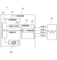
- FIG. 2 is a block diagram of a motor and a motor control device that constitute an actuator according to one embodiment of the present invention.
- the actuator 1 has a motor control device 10 and a stepping motor 20.
- the stepping motor 20 is driven by, for example, two-phase excitation of A phase and B phase.
- the stepping motor 20 has an A-phase coil and a B-phase coil (shown in FIG. 3).
- the stepping motor 20 is driven by supplying driving power from the motor control device 10 to the coils of each phase.
- the stepping motor 20 is used as an actuator for an air conditioner mounted on a vehicle, for example.
- the application of the stepping motor 20 and the actuator 1 is not limited to this.
- the motor control device 10 has a motor control circuit 12 and a drive circuit 14.
- the drive circuit 14 has a motor drive unit 142.
- the drive circuit 14 supplies drive power to the stepping motor 20 to drive the stepping motor 20.
- the motor control circuit 12 includes a CPU (central processing unit; an example of a speed setting unit, an example of a speed control unit) 122, an input voltage measurement unit 125, and a temperature measurement unit 128.
- the motor control circuit 12 controls the drive of the stepping motor 20 by controlling the drive circuit 14.
- the motor control circuit 12 is packaged as an IC (integrated circuit).
- the motor driving unit 142 applies a voltage to each phase coil of the stepping motor 20.
- a control signal is sent from the CPU 122 to the motor driving unit 142.
- the motor drive unit 142 applies a voltage based on the control signal.
- the drive circuit 14 and the stepping motor 20 are divided into four phases: A phase positive electrode (+), A phase negative electrode ( ⁇ ), B phase positive electrode (+), and B phase negative electrode ( ⁇ ). Connected by line.
- the motor driving unit 142 supplies driving power to the stepping motor 20 via these lines in accordance with the control signal.
- the control signal is a PWM signal, and the driving power changes according to the duty ratio of the PWM signal.
- the input voltage measurement unit 125 measures the input voltage input to the motor control device 10.
- the input voltage measurement unit 125 outputs the measurement result of the input voltage to the CPU 122.
- the temperature measuring unit 128 is, for example, a temperature sensor that measures the IC internal temperature of the motor control circuit 12.
- the temperature measurement unit 128 outputs temperature information indicating the temperature of the motor control circuit 12 to the CPU 122.
- the CPU 122 has functions as a speed setting unit and a speed control unit in the present embodiment.
- a speed setting unit the CPU 122 receives the input voltage measurement result output from the input voltage measurement unit 125 and the temperature information output from the temperature measurement unit 128.
- the speed setting unit sets a target value for the driving speed of the stepping motor 20 based on the measurement result of the input voltage measurement unit 125 and the measurement result of the temperature measurement unit 128.
- the speed setting unit sets a target value based on a driving speed setting value set in advance for each of a plurality of partial regions divided in a matrix by a threshold value related to input voltage and a threshold value related to temperature.
- CPU122 produces
- the CPU 122 outputs the generated control signal to the motor drive unit 142.
- FIG. 3 is a diagram schematically showing a circuit configuration of the stepping motor 20.
- the stepping motor 20 has two coils 21a and 21b, a rotor 22, and a plurality of stator yokes (not shown).
- the coils 21a and 21b are coils for exciting the stator yoke.
- the coils 21a and 21b are connected to the drive circuit 14, respectively.
- the coil 21a is an A-phase coil.
- the coil 21b is a B-phase coil. Coil currents having different phases flow through the coils 21a and 21b.
- the rotor 22 includes a permanent magnet that is multipolarly magnetized so that the S pole 22s and the N pole 22n are alternately reversed along the circumferential direction.
- the rotor 22 is shown in a simplified manner so that one S pole 22s and one N pole 22n are provided.
- the stator yoke is arranged around the rotor 22 and close to the outer peripheral portion of the rotor 22. The rotor 22 rotates when the phase of the coil current flowing through each of the coils 21a and 21b is periodically switched.
- the CPU 122 sets a target value for the driving speed of the stepping motor 20 based on the temperature measurement result and the input voltage measurement result as follows. Then, the CPU 122 generates the control signal so that the driving speed becomes the target value, thereby driving the stepping motor 20 at the set speed.
- the CPU 122 sets a target value for the driving speed based on a preset setting value for the driving speed as a speed setting unit.
- the set value is set in advance for each of a plurality of partial areas divided in a matrix by a threshold value related to the input voltage and a threshold value related to the temperature.
- the driving speed of each of the nine partial areas divided into a matrix of 3 rows and 3 columns (3 ⁇ 3) is divided into two threshold values related to input voltage and two threshold values related to temperature.
- a set value is set in advance.
- FIG. 4 is a diagram for explaining a setting example of the setting value of the driving speed.
- Sbc, Sca, Scb, Scc are set. That is, a total of nine set values Saa to Sac are set, one for each of the nine partial areas aa to cc.
- the partial areas aa to cc are divided in a matrix by threshold values V2 and V3 related to the input voltage and threshold values T2 and T3 related to the temperature. That is, the range from the input voltage V1 to V4 is divided into three voltage ranges (partition regions) Va, Vb, and Vc by the threshold values V2 and V3.
- the low voltage range Va is a range of V1 or more and less than V2.
- the intermediate voltage range Vb is a range of V2 or more and less than V3.
- the high voltage range Vc is a range of V3 or more and less than V4.
- the range from the input temperature T1 to T4 is divided into three temperature ranges (partition regions) Ta, Tb, and Tc by the threshold values T2 and T3.
- the low temperature range Ta is a range of T1 or more and less than T2.
- the intermediate temperature range Tb is a range of T2 or more and less than T3.
- the high temperature range Tc is a range of T3 or more and less than T4.
- the CPU 122 identifies a partial area corresponding to the current state among the nine partial areas aa to cc as a control area based on the input temperature measurement result and the input voltage measurement result. Then, a setting value corresponding to the specified control region is read, and the setting value is set as a target value for the driving speed. As a result, the CPU 122 outputs a control signal to the drive circuit 14 so that the drive speed of the stepping motor 20 is the same as the drive speed set value corresponding to the temperature and the input voltage. The motor 20 is controlled.
- the setting value of the driving speed is higher than the medium voltage and higher than the medium voltage for each range of low voltage, medium voltage, and high voltage divided by two thresholds with respect to the input voltage.
- the voltage is set to be larger, and the high temperature is larger than the low temperature in each of the low temperature, medium temperature, and high temperature ranges divided by two thresholds with respect to the temperature.
- the medium temperature is set higher than the high temperature.
- the set values Saa to Scc are such that the medium voltage range Vb is larger than the low voltage range Va and the high voltage range Vc is larger than the medium voltage range Vb with respect to the input voltage.
- the temperature is set so that the high temperature range Tc is larger than the low temperature range Ta and the intermediate temperature range Tb is larger than the high temperature range Tc.
- the magnitude of the driving speed that is, the magnitude of the set values Saa to Sac has the following relationship.
- each set value is set so that the relationship between the input voltage and the set value of the drive speed is as follows.
- the set value is set to be relatively small. Therefore, even if the input voltage is low, the torque of the stepping motor 20 can be ensured by reducing the driving speed.
- the set value is set to be relatively large. As a result, the drive speed can be increased and the motor can be rotated quickly.
- each set value is set so that the relationship between temperature and drive speed set value is as follows.
- the set value is set to a relatively small value.
- the grease applied to the movable parts such as the gears 26, 31, 32, and 33 becomes hard in the actuator 1, and the load on the stepping motor 20 increases.
- the set value is set to a small value so that a sufficient torque can be obtained even in an environment where the load becomes large. Thereby, the driving speed can be lowered and the stepping motor 20 can be driven with a large torque.
- the set value is set to a relatively small value.
- the resin of the gears 26, 31, 32, 33, etc. expands and clogs the gears, and the load on the stepping motor 20 increases. Therefore, the set value is set to be small as in the case of the low temperature environment.
- the extent to which the load of the stepping motor 20 increases is greater when the viscosity of the grease increases due to the lower temperature than when the material expands due to the higher temperature. Therefore, it is desirable to make the set value smaller in the low temperature range Ta than in the high temperature range Tc.
- the input voltage, temperature, and drive speed set values are set to the following values, for example.
- the reference input voltage is approximately 12 V and the actuator 1 is used in a room temperature environment.
- the lower limit value V1 and the upper limit value V4 of the input voltage, and the lower limit value T1 and the upper limit value T4 of the temperature can be set as appropriate. These lower limit values V1, T1 and upper limit values V4, T4 may not be set.
- the low voltage range Va is a range of all voltages below the threshold value V2
- the high voltage range Vc is a threshold value. It is in the range of all voltages of V3 or higher.
- the low temperature range Ta is a range of all temperatures below the threshold T2
- the high temperature range Tc is a range of all temperatures above the threshold T3.
- the specific values of the set value and the threshold value are appropriately determined based on experimental results and simulations according to the use and specifications of the actuator 1 and the stepping motor 20, the magnitude of the input voltage, the fluctuation amount of the input voltage, the assumed temperature, and the like. It can be set using the result.
- FIG. 5 is a flowchart for roughly explaining the target value setting process of the driving speed of the stepping motor 20 performed by the motor control device 10.
- step S11 the input voltage measurement unit 125 measures the input voltage (input voltage measurement step).
- step S12 the temperature is measured by the temperature measurement unit 128 (temperature measurement step). Note that step S11 and step S12 may be performed simultaneously or the order may be switched.
- step S13 the CPU 122 specifies a partial area including the current state among the nine partial areas aa to cc as the control area based on the temperature measurement result and the input voltage measurement result.
- step S14 the CPU 122 reads out the setting value of the driving speed corresponding to the specified control area as a speed setting unit, and sets the setting value as the target value of the driving speed (speed setting step).
- step S15 the CPU 122 outputs a control signal as a speed control unit according to the set target value of the driving speed (speed control step).
- the processing shown in FIG. 5 is performed after the CPU 122 receives a command for driving the stepping motor 20.
- the processing shown in FIG. 5 is completed and the target value of the driving speed is set, the driving speed is adjusted until the motor reaches the target point.
- the target value of the driving speed is set based on the setting value of the driving speed set in advance for each partial region determined by the relationship between the input voltage and the temperature. Since it can be set, the stepping motor 20 can be controlled so that an appropriate driving torque can be stably obtained under various environments.
- the set value of the driving speed is set according to the range of the input voltage. Therefore, the stepping motor 20 can be driven at a relatively high speed when a sufficient input voltage can be obtained, and torque shortage can be improved even in a situation where the voltage is relatively low.
- a threshold for dividing the range of the input voltage can be arbitrarily set, and the driving speed can be finely adjusted corresponding to each voltage range.
- the drive speed setting value is set according to the temperature range. Therefore, particularly when the temperature is high or low, torque shortage due to the influence of temperature can be improved.
- the stepping motor 20 can be driven while securing the torque by lowering the driving speed in a situation where the voltage is low and the temperature is low, such as during a cold start where torque shortage is likely to occur. it can.
- the internal temperature of the IC is measured and used to determine the target value of the driving speed.
- a temperature close to the temperature of the part that is slightly separated from the stepping motor 20 where the temperature may fluctuate due to driving and causes the increase in load due to the temperature is measured, and the target value of the driving speed is measured using the measurement result. Therefore, the stepping motor 20 can be driven at an appropriate driving speed while ensuring the torque according to the situation. Note that the temperature of other parts may be measured regardless of the IC internal temperature.
- a predetermined time elapses after the driving of the stepping motor 20 is started. Later, control may be performed so that the stepping motor 20 is driven at a predetermined driving speed higher than that.
- the predetermined time it is usually possible to set a time taken from the start of the driving of the stepping motor 20 until the driving is stabilized. As a result, torque can be secured to drive the stepping motor 20 at a cold start or the like, and the stepping motor 20 can be driven at a normal driving speed after a stable driving state is achieved.
- the number of divisions of the matrix may be two rows and two columns (2 ⁇ 2) or more, and the number of threshold values for the input voltage may be different from the number of threshold values for the temperature.
- 2 ⁇ 3, 2 ⁇ 4, 4 ⁇ 4, and the like can be set as appropriate.
- the configuration of the actuator described above is an example, and a configuration different from that described above may be used.
- control circuit Only a part of the control circuit may be configured as an integrated circuit. Further, a part of the motor control device that is different from the control circuit may be configured as an integrated circuit. The entire motor control device may be configured as an integrated circuit.
- actuators such as stepping motors and motor control devices is not limited to the above.
- the processing in the above-described embodiment may be performed by software or by using a hardware circuit.
- a program for executing the processing in the above-described embodiment can be provided, or the program can be recorded on a recording medium such as a CD-ROM, flexible disk, hard disk, ROM, RAM, memory card, and provided to the user. It may be.
- the program may be downloaded to the apparatus via a communication line such as the Internet.
- the processing described in the above flowchart and text is executed by a CPU or the like according to the program.
Landscapes
- Engineering & Computer Science (AREA)
- Power Engineering (AREA)
- Control Of Stepping Motors (AREA)
Abstract
幅広い環境下で駆動トルクを確保してモータを駆動することができるモータ制御回路を提供する。 モータ制御回路(12)は、入力電圧測定部(125)と、温度計測部(128)と、速度設定部と、速度制御部とを備える。入力電圧測定部(125)は、モータ制御装置(10)に入力される入力電圧を測定する。温度計測部(128)は、温度を計測する。速度設定部は、入力電圧測定部(125)の測定結果と温度計測部(128)の計測結果とに基づいて、また、入力電圧に関する閾値と温度に関する閾値とでマトリクス状に区分される複数の部分領域毎に予め設定された駆動速度の設定値に基づいて、ステッピングモータ(20)の駆動速度の目標値を設定する。速度制御部は、速度設定部で設定された駆動速度の目標値に応じて、駆動速度を制御する。
Description
この発明は、モータ制御回路、モータ制御装置、アクチュエータ及びステッピングモータの制御方法に関し、特に、ステッピングモータを利用したアクチュエータに用いられるモータ制御回路、モータ制御装置、アクチュエータ及びステッピングモータの制御方法に関する。
ステッピングモータは、その制御が容易であることなど種々の特長を有するものであり、各種アクチュエータなどに広く用いられている(例えば、下記特許文献1参照)。
このようなステッピングモータを用いたアクチュエータについて、要求されるトルクや駆動速度の仕様は、アクチュエータの用途等によって適宜設定される。他方、アクチュエータが使用される環境としては、温度や、モータ制御装置に入力される入力電圧が、変動する場合がある。
このような温度や入力電圧の条件が異なる幅広い使用環境において、設定された仕様を満たすようにステッピングモータを駆動させるのは、困難である。具体的には、例えば、特にコールドスタート時など、入力電圧が比較的低く、温度が比較的低いときには、アクチュエータのトルクが不足するという問題がある。
この発明はそのような問題点を解決するためになされたものであり、幅広い使用環境下で駆動トルクを確保してモータを駆動することができるモータ制御回路、モータ制御装置、アクチュエータ及びステッピングモータの制御方法を提供することを目的としている。
上記目的を達成するためこの発明のある局面に従うと、ステッピングモータを駆動させるモータ制御装置に用いられるモータ制御回路は、モータ制御装置に入力される入力電圧を測定する入力電圧測定部と、温度を計測する温度計測部と、入力電圧測定部の測定結果と温度計測部の計測結果とに基づいて、ステッピングモータ駆動速度の目標値を設定する速度設定部と、速度設定部で設定された駆動速度の目標値に応じて、駆動速度を制御する速度制御部とを備え、速度設定部は、入力電圧に関する閾値と温度に関する閾値とでマトリクス状に区分される複数の部分領域毎に予め設定された駆動速度の設定値に基づいて、目標値の設定を行う。
好ましくは、速度設定部は、入力電圧に関する2つの閾値と温度に関する2つの閾値とで3行3列のマトリクス状に区分される9個の部分領域毎に予め設定された設定値に基づいて、目標値の設定を行う。
好ましくは、設定値は、入力電圧に対して、2つの閾値で区分される低電圧、中電圧、高電圧の各範囲について、低電圧よりも中電圧のほうが大きくなり、中電圧よりも高電圧のほうが大きくなるように、設定されており、かつ、温度に対して、2つの閾値で区分される低温度、中温度、高温度の各範囲について、中温度よりも高温度のほうが大きくなり、高温度よりも低温度のほうが大きくなるように、設定されている。
この発明の他の局面に従うと、モータ制御装置は、上記に記載のモータ制御回路と、ステッピングモータを駆動させるための駆動回路とを備え、モータ制御回路は、速度制御部から駆動速度を制御するための制御信号を出力し、駆動回路は、制御信号に基づいてステッピングモータのコイルに駆動電流を流す。
この発明のさらに他の局面に従うと、アクチュエータは、駆動力を発生させるステッピングモータと、上記に記載のモータ制御回路と、速度制御部から駆動速度を制御するために出力された制御信号に基づいてステッピングモータのコイルに駆動電流を流す駆動回路とを有する。
この発明のさらに他の局面に従うと、ステッピングモータの制御方法は、入力電圧を測定する入力電圧測定ステップと、温度を計測する温度計測ステップと、入力電圧測定ステップの測定結果と温度計測ステップの計測結果とに基づいて、ステッピングモータの駆動速度の目標値を設定する速度設定ステップと、速度設定ステップで設定された駆動速度の目標値に応じて、駆動速度を制御する速度制御ステップとを備え、速度設定ステップは、入力電圧に関する閾値と温度に関する閾値とでマトリクス状に区分される複数の部分領域毎に予め設定された駆動速度の設定値に基づいて、目標値の設定を行う。
これらの発明に従うと、幅広い使用環境下で駆動トルクを確保してモータを駆動することができるモータ制御回路、モータ制御装置、アクチュエータ及びステッピングモータの制御方法を提供することができる。
以下、本発明の実施の形態の1つにおけるモータ制御装置について説明する。
モータ制御装置は、例えば、複数相のコイルを有するステッピングモータを駆動させるためのものである。モータ制御装置は、ステッピングモータを駆動させるために各相のコイルの通電状態を制御する。本実施の形態において、モータ制御装置は、ステッピングモータのコイルに通電する駆動回路と、駆動回路の制御を行うモータ制御回路とを有している。
モータ制御装置と、それにより駆動されるステッピングモータとその他の機構部品とで、アクチュエータが構成される。アクチュエータにおいて、ステッピングモータは、駆動回路から駆動電力が供給されることで駆動される。アクチュエータにおいて、モータ制御回路によって駆動回路が制御されることにより、ステッピングモータの駆動が制御される。
[実施の形態]
図1は、本実施の形態におけるモータ制御装置が用いられるアクチュエータの一例を示す分解斜視図である。
図1に示されるように、アクチュエータ1は、ケース51とカバー52とで覆われている。アクチュエータ1の内部には、モータ制御装置10、ステッピングモータ20、2次ギヤ31、3次ギヤ32、出力ギヤ33などが収納されている。ケース51の底面には、出力ギヤ33に設けられている外部出力ギヤが露出し、この外部出力ギヤよりアクチュエータ1の駆動力が外部に伝達される。
ステッピングモータ20は、アクチュエータ1の駆動力を発生させる。ステッピングモータ20の出力軸25には、1次ギヤ26が取り付けられている。ステッピングモータ20の1次ギヤ26は、2次ギヤ31と噛み合う。2次ギヤ31は、3次ギヤ32と噛み合う。3次ギヤ32は、出力ギヤ33と噛み合う。
モータ制御装置10は、プリント基板42や、プリント基板42とステッピングモータ20のモータ端子29とを接続するフレキシブルプリント基板43などを有している。プリント基板42には、ステッピングモータ20を駆動する駆動回路14(図2に示す)や、その制御を行うモータ制御回路12(図2に示す)などが設けられている。プリント基板42には、ケース51及びカバー52の外側に露出する外部接続端子41が設けられている。外部接続端子41を介して外部からモータ制御装置10に電圧が入力されたり、外部機器からの指示信号を受けたりすることで、モータ制御装置10が動作する。
モータ制御装置10は、入力された入力電圧に基づいてステッピングモータ20に駆動電力を供給し、ステッピングモータ20を駆動させる。ステッピングモータ20が駆動すると、出力軸25とともに1次ギヤ26が回転する。この回転の駆動力は、2次ギヤ31、3次ギヤ32、出力ギヤ33、外部出力ギヤと順に伝達され、外部出力ギヤにより外部に出力される。
なお、ケース51及びカバー52の内部に収納されている回路は、例えば駆動回路14だけであってもよい。この場合、モータ制御装置10は、ケース51及びカバー52の内部の駆動回路14と、その駆動回路14に接続された外部のモータ制御回路12によって構成されるようにしてもよい。
図2は、本発明の実施の形態の1つにおけるアクチュエータの構成をなすモータとモータ制御装置のブロック図である。
図2に示されるように、アクチュエータ1は、モータ制御装置10と、ステッピングモータ20とを有している。ステッピングモータ20は、例えば、A相及びB相の2相励磁で駆動される。ステッピングモータ20は、A相のコイル及びB相のコイル(図3に示す。)を有している。ステッピングモータ20は、モータ制御装置10から各相のコイルに駆動電力が供給されて駆動される。ステッピングモータ20は、例えば、車両に搭載される空調装置用のアクチュエータとして利用される。なお、ステッピングモータ20及びアクチュエータ1の用途はこれに限られるものではない。
モータ制御装置10は、モータ制御回路12と、駆動回路14とを有している。
駆動回路14は、モータ駆動部142を有している。駆動回路14は、ステッピングモータ20に駆動電力を供給し、ステッピングモータ20を駆動する。
モータ制御回路12は、CPU(中央演算処理装置;速度設定部の一例、速度制御部の一例)122と、入力電圧測定部125と、温度計測部128とを有している。モータ制御回路12は、駆動回路14の制御を行うことで、ステッピングモータ20の駆動を制御する。本実施の形態において、モータ制御回路12は、IC(集積回路)としてパッケージ化されている。
モータ駆動部142は、ステッピングモータ20の各相のコイルに電圧を印加する。モータ駆動部142には、CPU122から制御信号が送られる。モータ駆動部142は、制御信号に基づいて、電圧を印加する。本実施の形態では、駆動回路14とステッピングモータ20とは、A相の正極(+)、A相の負極(-)、B相の正極(+)、B相の負極(-)の4つのラインで接続されている。モータ駆動部142は、制御信号に応じて、これらの各ラインを介して、ステッピングモータ20に駆動電力を供給する。制御信号は、PWM信号であり、PWM信号のデューティ比に応じて駆動電力が変化する。
入力電圧測定部125は、モータ制御装置10に入力される入力電圧を測定する。入力電圧測定部125は、入力電圧の測定結果を、CPU122に出力する。
温度計測部128は、例えば、モータ制御回路12のIC内部温度を測定する温度センサである。温度計測部128は、モータ制御回路12の温度を示す温度情報をCPU122に出力する。
CPU122は、本実施の形態において、速度設定部および速度制御部としての機能を備えている。CPU122には、速度設定部として、入力電圧測定部125から出力された入力電圧の測定結果と、温度計測部128から出力された温度情報とが入力される。速度設定部は、入力電圧測定部125の測定結果と温度計測部128の計測結果とに基づいて、ステッピングモータ20の駆動速度の目標値を設定する。また、速度設定部は、入力電圧に関する閾値と温度に関する閾値とでマトリクス状に区分される複数の部分領域毎に予め設定された駆動速度の設定値に基づいて、目標値の設定を行う。そして、CPU122は、速度制御部として、速度設定部で設定された駆動速度の目標値に応じて、ステッピングモータ20の駆動速度を制御するための制御信号を生成する。CPU122は、生成した制御信号を、モータ駆動部142に出力する。
図3は、ステッピングモータ20の回路構成を模式的に示す図である。
図3に示されるように、ステッピングモータ20は、2つのコイル21a,21bと、ロータ22と、複数のステータヨーク(図示せず)とを有している。
コイル21a,21bは、それぞれ、ステータヨークを励磁するコイルである。コイル21a,21bは、それぞれ、駆動回路14に接続されている。コイル21aは、A相のコイルである。コイル21bは、B相のコイルである。コイル21a,21bには、それぞれ異なる位相のコイル電流が流される。
ロータ22は、円周方向に沿って、S極22sとN極22nとが交互に反転するように多極着磁された永久磁石を備える。なお、図3においては、ロータ22は、S極22sとN極22nとが1つずつ設けられているように簡略化されて示されている。ステータヨークは、ロータ22の周囲に、ロータ22の外周部に接近して配置されている。ロータ22は、コイル21a,21bのそれぞれに流れるコイル電流の位相が周期的に切り替えられることで回転する。
本実施の形態において、CPU122は、以下のようにして、温度の計測結果と、入力電圧の測定結果とに基づいて、ステッピングモータ20の駆動速度の目標値を設定する。そして、CPU122は、駆動速度が目標値となるように制御信号を生成することで、ステッピングモータ20を設定速度で駆動させる。
すなわち、CPU122は、速度設定部として、予め設定された、駆動速度の設定値に基づいて、駆動速度の目標値を設定する。設定値は、入力電圧に関する閾値と、温度に関する閾値とでマトリクス状に区分される複数の部分領域毎に予め設定されている。本実施の形態においては、入力電圧に関する2つの閾値と、温度に関する2つの閾値とで、3行3列(3×3)のマトリクス状に区分される9個の部分領域毎に、駆動速度の設定値が予め設定されている。
図4は、駆動速度の設定値の設定例を説明する図である。
図4においては、上述のように3行3列の部分領域aa,ab,ac,ba,bb,bc,ca,cb,ccのそれぞれについて1個の設定値Saa,Sab,Sac,Sba,Sbb,Sbc,Sca,Scb,Sccが設定されている例が示されている。すなわち、9個の部分領域aaからccのそれぞれに1個ずつ、合計9個の設定値SaaからSacが設定されている。
各部分領域aaからccは、入力電圧に関する閾値V2,V3と、温度に関する閾値T2,T3とでマトリクス状に区分されている。すなわち、閾値V2,V3によって、入力電圧V1からV4までの範囲が、3つの電圧範囲(区分領域)Va,Vb,Vcに区切られている。低電圧範囲Vaは、V1以上V2未満の範囲である。中電圧範囲Vbは、V2以上V3未満の範囲である。高電圧範囲Vcは、V3以上V4未満の範囲である。また、閾値T2,T3によって、入力温度T1からT4までの範囲が、3つの温度範囲(区分領域)Ta,Tb,Tcに区切られている。低温度範囲Taは、T1以上T2未満の範囲である。中温度範囲Tbは、T2以上T3未満の範囲である。高温度範囲Tcは、T3以上T4未満の範囲である。この3つの電圧範囲Va,Vb,Vcと3つの温度範囲Ta,Tb,Tcとの組合せによって、9個の部分領域aaからccがマトリクス状に形成されている。
CPU122は、入力された温度の計測結果と入力電圧の測定結果とに基づいて、9個の部分領域aaからccのうち、現在の状態に対応する部分領域を制御領域として特定する。そして、特定した制御領域に対応する設定値を読み出し、その設定値を駆動速度の目標値として設定する。これにより、CPU122は、ステッピングモータ20の駆動速度が、温度と入力電圧とに応じた駆動速度の設定値と同じ大きさの駆動速度になるように、駆動回路14に制御信号を出力し、ステッピングモータ20の制御を行う。
駆動速度の設定値は、入力電圧に対して、2つの閾値で区分される低電圧、中電圧、高電圧の各範囲について、低電圧よりも前記中電圧のほうが大きくなり、中電圧よりも高電圧のほうが大きくなるように、設定されており、かつ、温度に対して、2つの閾値で区分される低温度、中温度、高温度の各範囲について、低温度よりも高温度のほうが大きくなり、高温度よりも中温度のほうが大きくなるように、設定されている。
具体的には、設定値SaaからSccは、入力電圧に対して、低電圧範囲Vaよりも中電圧範囲Vbのほうが大きくなり、中電圧範囲Vbよりも高電圧範囲Vcのほうが大きくなるように、設定されており、かつ、温度に対して、低温度範囲Taよりも高温度範囲Tcのほうが大きくなり、高温度範囲Tcよりも中温度範囲Tbのほうが大きくなるように、設定されている。
すなわち、駆動速度の大きさすなわち設定値SaaからSacの大きさは、以下のような関係になる。
入力電圧について、(電圧範囲Vaの場合)≦(Vbの場合)≦(Vcの場合)
温度について、(温度範囲Taの場合)≦(Tcの場合)≦(Tbの場合)
例えば、低温度範囲T1の状況下で比較すると、以下のような関係になっている。
(低電圧低温度領域aaの設定値Saa)≦(中電圧低温度領域baの設定値Sba)≦(高電圧低温度領域caの設定値Sca)
また、例えば、低電圧範囲V1の状況下で比較すると、以下のような関係になっている。
(低電圧低温度領域aaの設定値Saa)≦(低電圧高温度領域acの設定値Sac)≦(低電圧中温度領域abの設定値Sab)
本実施の形態において、入力電圧と駆動速度の設定値との関係性が次のようになるように、各設定値が設定されている。
すなわち、低電圧範囲Vaでは、設定値が比較的小さくなるように設定されている。これにより、入力電圧が低くても、駆動速度を低くすることで、ステッピングモータ20のトルクを確保することができる。
他方、高電圧範囲Vcでは、設定値が比較的大きくなるように設定されている。これにより、駆動速度を高くして、早く回転させることができる。
また、温度と駆動速度の設定値との関係性が次のようになるように、各設定値が設定されている。
すなわち、低温度範囲Taでは、設定値が比較的小さい値に設定されている。低温度環境においては、アクチュエータ1において、ギヤ26,31,32,33等の可動部に塗布されているグリスが固くなり、ステッピングモータ20にとって負荷が大きくなる。設定値は、このように負荷が大きくなる環境下でも十分なトルクが得られるように、小さい値に設定されている。これにより、駆動速度を低くして、大きいトルクでステッピングモータ20を駆動させることができる。
また、高温度範囲Tcでも、設定値が比較的小さい値に設定されている。高温度環境においては、ギヤ26,31,32,33等の樹脂が膨張してギヤ間が詰まり、ステッピングモータ20にとって負荷が大きくなる。そのため、低温度環境の場合と同様に、設定値が小さく設定されている。なお、ステッピングモータ20の負荷が増大する程度は、温度が高くなることにより素材が膨張する場合よりも、温度が低くなることによりグリスの粘度が増大する場合のほうが大きい。そのため、高温度範囲Tcよりも低温度範囲Taのほうが、設定値を小さくすることが望ましい。
本実施の形態において、入力電圧と、温度と、駆動速度の設定値とは、例えば次のような値に設定されている。ここでは、基準となる入力電圧が略12Vである場合であって、室温環境で用いられるアクチュエータ1を想定する。
閾値について、入力電圧の下限値V1や上限値V4、温度の下限値T1や上限値T4は、適宜設定可能である。これらの下限値V1,T1や上限値V4,T4は、設定されていなくてもよく、その場合には、低電圧範囲Vaは閾値V2以下のすべての電圧の範囲となり、高電圧範囲Vcは閾値V3以上のすべての電圧の範囲となる。また、低温度範囲Taは閾値T2以下のすべての温度の範囲となり、高温度範囲Tcは閾値T3以上のすべての温度の範囲となる。
なお、設定値や閾値の具体的な値は、アクチュエータ1やステッピングモータ20の用途や仕様、入力電圧の大きさ、入力電圧の変動量、想定される温度等に応じて、適宜実験結果やシミュレーション結果などを利用して設定することができる。
図5は、モータ制御装置10が行うステッピングモータ20の駆動速度の目標値設定処理を大まかに説明するフローチャートである。
図5に示されるように、ステップS11において、入力電圧測定部125により、入力電圧が測定される(入力電圧測定ステップ)。
ステップS12において、温度計測部128により、温度が計測される(温度計測ステップ)。なお、ステップS11とステップS12とは、同時に行われたり、順序が入れ替わったりしてもよい。
ステップS13において、CPU122は、温度の計測結果と、入力電圧の測定結果とに基づいて、9個の部分領域aaからccのうち現在の状態を含む部分領域を制御領域として特定する。
ステップS14において、CPU122は、速度設定部として、特定した制御領域に対応する駆動速度の設定値を読み出し、その設定値を駆動速度の目標値として設定する(速度設定ステップ)。
ステップS15において、CPU122は、速度制御部として、設定された駆動速度の目標値に応じて、制御信号を出力する(速度制御ステップ)。
例えば、図5において示される処理は、ステッピングモータ20を駆動するためのコマンドをCPU122が受け付けてから行われる。そして、図5において示される処理が終了し、駆動速度の目標値の設定が行われると、モータが目標地点に到達するまで駆動速度が調整される。
[実施の形態における効果]
以上のように構成されたモータ制御装置10を用いたアクチュエータ1では、入力電圧と温度との関係で定まる部分領域毎に予め設定された駆動速度の設定値に基づいて、駆動速度の目標値を設定できるので、様々な環境下で適切な駆動トルクが安定して得られるように、ステッピングモータ20の制御を行うことができる。
すなわち、入力電圧の範囲に応じて、駆動速度の設定値が設定されている。そのため、十分な入力電圧が得られるときにはステッピングモータ20を比較的高速で駆動させることができ、かつ、比較的低電圧である状況においても、トルク不足を改善することができる。また、入力電圧の範囲を区分する閾値を任意に設定でき、各電圧範囲に対応して細かく駆動速度を調整することが可能となる。
また、温度の範囲に応じて、駆動速度の設定値が設定されている。そのため、特に高温である場合や低温である場合に、温度の影響によるトルク不足を改善することができる。
特に、本実施の形態においては、トルク不足が発生しやすいコールドスタート時などの低電圧かつ低温度である状況において、駆動速度を低くしてトルクを確保しながら、ステッピングモータ20を駆動させることができる。
特に、本実施の形態では、ICの内部温度が計測され、駆動速度の目標値の決定に利用される。駆動により温度が変動することがあるステッピングモータ20から若干離れた、温度の影響による負荷の増大の要因となる部位の温度に近い温度を計測し、その計測結果を利用して駆動速度の目標値を決定することができるので、状況に応じてトルクを確保できるようにしつつ、適切な駆動速度でステッピングモータ20を駆動することができる。なお、温度はIC内部温度にかかわらず、他の部位の温度が計測されるようにしてもよい。
[その他]
例えば上記のような低温度かつ低電圧である状況などにおいて、他の場合よりも低い駆動速度でステッピングモータ20を駆動する場合には、ステッピングモータ20の駆動を開始してから、所定時間の経過後に、それより高速な所定の駆動速度でステッピングモータ20を駆動させるように制御が行われてもよい。
上記の場合、所定時間としては、通常、ステッピングモータ20の駆動を開始してから駆動が安定するまでにかかる時間を設定することができる。これにより、コールドスタート時などにはトルクを確保してステッピングモータ20を駆動させ、かつ、安定して駆動可能な状態になってからはステッピングモータ20を通常の駆動速度で駆動させることができる。
マトリクスの分割数は、2行2列(2×2)以上であればよく、また、入力電圧についての閾値の数と温度についての閾値の数とが異なっていてもよい。例えば、2×3、2×4、4×4など、適宜設定することができる。
上述のアクチュエータの構成は一例であり、上述とは異なる構成であってもよい。
制御回路の一部分のみが集積回路として構成されていてもよい。また、モータ制御装置のうち、制御回路とは異なる部分の一部が集積回路として構成されていてもよい。モータ制御装置の全部が集積回路として構成されていてもよい。
ステッピングモータやモータ制御装置など、アクチュエータのハードウェア構成は上述に限られるものではない。
上述の実施の形態における処理は、ソフトウェアによって行っても、ハードウェア回路を用いて行ってもよい。
上述の実施の形態における処理を実行するプログラムを提供することもできるし、そのプログラムをCD-ROM、フレキシブルディスク、ハードディスク、ROM、RAM、メモリカードなどの記録媒体に記録してユーザに提供することにしてもよい。プログラムはインターネットなどの通信回線を介して、装置にダウンロードするようにしてもよい。上記のフローチャート及び文章で説明された処理は、そのプログラムに従ってCPUなどにより実行される。
上記実施の形態は、すべての点で例示であって制限的なものではないと考えられるべきである。本発明の範囲は上記した説明ではなくて特許請求の範囲によって示され、特許請求の範囲と均等の意味及び範囲内でのすべての変更が含まれることが意図される。
1 アクチュエータ
10 モータ制御装置
12 モータ制御回路
14 駆動回路
20 ステッピングモータ
21a,21b コイル
122 CPU(中央演算処理装置;速度設定部の一例、速度制御部の一例)
125 入力電圧測定部
128 温度計測部
142 モータ駆動部
10 モータ制御装置
12 モータ制御回路
14 駆動回路
20 ステッピングモータ
21a,21b コイル
122 CPU(中央演算処理装置;速度設定部の一例、速度制御部の一例)
125 入力電圧測定部
128 温度計測部
142 モータ駆動部
Claims (6)
- ステッピングモータを駆動させるモータ制御装置に用いられるモータ制御回路であって、
前記モータ制御装置に入力される入力電圧を測定する入力電圧測定部と、
温度を計測する温度計測部と、
前記入力電圧測定部の測定結果と前記温度計測部の計測結果とに基づいて、前記ステッピングモータ駆動速度の目標値を設定する速度設定部と、
前記速度設定部で設定された前記駆動速度の前記目標値に応じて、前記駆動速度を制御する速度制御部とを備え、
前記速度設定部は、前記入力電圧に関する閾値と温度に関する閾値とでマトリクス状に区分される複数の部分領域毎に予め設定された前記駆動速度の設定値に基づいて、前記目標値の設定を行う、モータ制御回路。 - 前記速度設定部は、前記入力電圧に関する2つの閾値と前記温度に関する2つの閾値とで3行3列のマトリクス状に区分される9個の部分領域毎に予め設定された前記設定値に基づいて、前記目標値の設定を行う、請求項1に記載のモータ制御回路。
- 前記設定値は、
前記入力電圧に対して、前記2つの閾値で区分される低電圧、中電圧、高電圧の各範囲について、前記低電圧よりも前記中電圧のほうが大きくなり、前記中電圧よりも前記高電圧のほうが大きくなるように、設定されており、かつ、
前記温度に対して、前記2つの閾値で区分される低温度、中温度、高温度の各範囲について、前記低温度よりも前記高温度のほうが大きくなり、前記高温度よりも前記中温度のほうが大きくなるように、設定されている、請求項2に記載のモータ制御回路。 - 請求項1から3のいずれか1項に記載のモータ制御回路と、
前記ステッピングモータを駆動させるための駆動回路とを備え、
前記モータ制御回路は、前記速度制御部から前記駆動速度を制御するための制御信号を出力し、
前記駆動回路は、前記制御信号に基づいて前記ステッピングモータのコイルに駆動電流を流す、モータ制御装置。 - 駆動力を発生させるステッピングモータと、
請求項1から3のいずれか1項に記載のモータ制御回路と、
前記速度制御部から前記駆動速度を制御するために出力された制御信号に基づいて前記ステッピングモータのコイルに駆動電流を流す駆動回路とを有する、アクチュエータ。 - 入力電圧を測定する入力電圧測定ステップと、
温度を計測する温度計測ステップと、
前記入力電圧測定ステップの測定結果と前記温度計測ステップの計測結果とに基づいて、前記ステッピングモータの駆動速度の目標値を設定する速度設定ステップと、
前記速度設定ステップで設定された前記駆動速度の前記目標値に応じて、前記駆動速度を制御する速度制御ステップとを備え、
前記速度設定ステップは、前記入力電圧に関する閾値と前記温度に関する閾値とでマトリクス状に区分される複数の部分領域毎に予め設定された前記駆動速度の設定値に基づいて、前記目標値の設定を行う、ステッピングモータの制御方法。
Priority Applications (2)
| Application Number | Priority Date | Filing Date | Title |
|---|---|---|---|
| DE112017003908.8T DE112017003908T5 (de) | 2016-08-03 | 2017-07-21 | Motorsteuerschaltung, Motorsteuervorrichtung, Aktuator und Schrittmotorsteuerverfahren |
| US16/261,719 US10742147B2 (en) | 2016-08-03 | 2019-01-30 | Motor control circuit, motor control device, actuator and control method for stepping motor |
Applications Claiming Priority (2)
| Application Number | Priority Date | Filing Date | Title |
|---|---|---|---|
| JP2016-153172 | 2016-08-03 | ||
| JP2016153172A JP6603629B2 (ja) | 2016-08-03 | 2016-08-03 | モータ制御回路、モータ制御装置、アクチュエータ及びステッピングモータの制御方法 |
Related Child Applications (1)
| Application Number | Title | Priority Date | Filing Date |
|---|---|---|---|
| US16/261,719 Continuation US10742147B2 (en) | 2016-08-03 | 2019-01-30 | Motor control circuit, motor control device, actuator and control method for stepping motor |
Publications (1)
| Publication Number | Publication Date |
|---|---|
| WO2018025665A1 true WO2018025665A1 (ja) | 2018-02-08 |
Family
ID=61073896
Family Applications (1)
| Application Number | Title | Priority Date | Filing Date |
|---|---|---|---|
| PCT/JP2017/026467 Ceased WO2018025665A1 (ja) | 2016-08-03 | 2017-07-21 | モータ制御回路、モータ制御装置、アクチュエータ及びステッピングモータの制御方法 |
Country Status (4)
| Country | Link |
|---|---|
| US (1) | US10742147B2 (ja) |
| JP (1) | JP6603629B2 (ja) |
| DE (1) | DE112017003908T5 (ja) |
| WO (1) | WO2018025665A1 (ja) |
Families Citing this family (1)
| Publication number | Priority date | Publication date | Assignee | Title |
|---|---|---|---|---|
| JP7479217B2 (ja) * | 2020-06-22 | 2024-05-08 | ミネベアミツミ株式会社 | モータ駆動制御装置、アクチュエータ、およびモータ駆動制御方法 |
Citations (2)
| Publication number | Priority date | Publication date | Assignee | Title |
|---|---|---|---|---|
| JPH1118491A (ja) * | 1997-06-27 | 1999-01-22 | Sanden Corp | 電動アクチュエータおよびその制御方法 |
| JPH11294196A (ja) * | 1998-04-16 | 1999-10-26 | Toyota Motor Corp | ディーゼル機関の吸気絞り弁制御方法及び制御装置 |
Family Cites Families (13)
| Publication number | Priority date | Publication date | Assignee | Title |
|---|---|---|---|---|
| US5264770A (en) * | 1992-03-12 | 1993-11-23 | Coutu David J | Stepper motor driver circuit |
| JPH07170790A (ja) | 1993-12-15 | 1995-07-04 | Nissan Motor Co Ltd | ステッピングモータにより駆動されるアクチュエータの位置制御装置 |
| JPH10248295A (ja) * | 1997-03-03 | 1998-09-14 | Zexel Corp | アクチュエータ制御装置 |
| DE69820344T2 (de) | 1997-06-26 | 2004-11-18 | Toyota Jidosha K.K., Toyota | Vorrichtung und Verfahren zur Steuerung einer Drosselklappe in einer Brennkraftmaschine |
| US7338260B2 (en) * | 2004-03-17 | 2008-03-04 | Baxier International Inc. | System and method for controlling current provided to a stepping motor |
| US7622876B2 (en) * | 2006-07-31 | 2009-11-24 | Danaher Motion, Llc | Overload prevention device for permanent magnet DC motors |
| US7446494B2 (en) * | 2006-10-10 | 2008-11-04 | Honeywell International Inc. | HVAC actuator having torque compensation |
| JP2009213344A (ja) * | 2008-02-04 | 2009-09-17 | Rohm Co Ltd | モータドライバ回路 |
| US8659259B2 (en) * | 2009-09-04 | 2014-02-25 | Canon Kabushiki Kaisha | Stepping motor driving apparatus |
| CN102398800A (zh) * | 2010-07-02 | 2012-04-04 | 株式会社东芝 | 马达控制装置、图像形成装置、马达控制方法 |
| US9030143B2 (en) * | 2011-10-31 | 2015-05-12 | Regal Beloit America, Inc. | Method and system of limiting current to a motor |
| JP2015035926A (ja) * | 2013-08-09 | 2015-02-19 | ミネベア株式会社 | ステッピングモータの制御装置及びステッピングモータの制御方法 |
| US9647588B2 (en) * | 2015-02-26 | 2017-05-09 | Texas Instruments Incorporated | Decay lock loop for time varying current regulation in electric motors |
-
2016
- 2016-08-03 JP JP2016153172A patent/JP6603629B2/ja active Active
-
2017
- 2017-07-21 DE DE112017003908.8T patent/DE112017003908T5/de active Pending
- 2017-07-21 WO PCT/JP2017/026467 patent/WO2018025665A1/ja not_active Ceased
-
2019
- 2019-01-30 US US16/261,719 patent/US10742147B2/en active Active
Patent Citations (2)
| Publication number | Priority date | Publication date | Assignee | Title |
|---|---|---|---|---|
| JPH1118491A (ja) * | 1997-06-27 | 1999-01-22 | Sanden Corp | 電動アクチュエータおよびその制御方法 |
| JPH11294196A (ja) * | 1998-04-16 | 1999-10-26 | Toyota Motor Corp | ディーゼル機関の吸気絞り弁制御方法及び制御装置 |
Also Published As
| Publication number | Publication date |
|---|---|
| JP6603629B2 (ja) | 2019-11-06 |
| DE112017003908T5 (de) | 2019-05-09 |
| US10742147B2 (en) | 2020-08-11 |
| JP2018023225A (ja) | 2018-02-08 |
| US20190157999A1 (en) | 2019-05-23 |
Similar Documents
| Publication | Publication Date | Title |
|---|---|---|
| CN101335495B (zh) | 三相无刷电动机的控制装置 | |
| US10523145B2 (en) | Motor control circuit, motor control device, actuator and control method for stepping motor | |
| JP4959460B2 (ja) | モータ起動装置及びモータ起動方法 | |
| US10742146B2 (en) | Motor control circuit, motor control device, actuator and control method for stepping motor | |
| JP2014143775A (ja) | モータ制御装置及びモータの制御方法 | |
| JP6603629B2 (ja) | モータ制御回路、モータ制御装置、アクチュエータ及びステッピングモータの制御方法 | |
| JP2021197760A (ja) | モータ駆動制御装置、アクチュエータ、およびモータ駆動制御方法 | |
| JP6585651B2 (ja) | モータ制御装置及びステッピングモータの制御方法 | |
| US10014806B2 (en) | Stepping motor driving device and timepiece | |
| JP7530760B2 (ja) | モータ駆動制御装置、アクチュエータ、およびモータ駆動制御方法 | |
| CN115411986A (zh) | 马达驱动控制装置、马达单元以及马达驱动控制方法 | |
| JP2022002448A (ja) | モータ駆動制御装置、アクチュエータ、およびモータ駆動制御方法 | |
| US10469010B2 (en) | Motor drive controller, control method for motor drive controller, control program for motor drive controller, and method for determining number of divisions of basic step angle | |
| RU2656882C1 (ru) | Исполнительный агрегат электропривода | |
| JP2021027746A (ja) | モータ駆動制御装置、モータユニット、およびモータ駆動制御方法 | |
| KR20150051565A (ko) | 모터 | |
| JP5847470B2 (ja) | 指針装置 | |
| JP2020048335A (ja) | アクチュエータ制御装置、その制御方法、および制御プログラム | |
| Reytskiy et al. | Selection and calculation of stepper motors for CNC | |
| KR100447850B1 (ko) | 스텝모터의 제어장치 및 제어방법 | |
| TW202404251A (zh) | 處理裝置、電動車輛、處理方法、及激磁波形生成程式 | |
| Pettersson et al. | Modeling and Control of Electromechanical Actuators for Heavy Vehicle Applications | |
| JP2013219891A (ja) | モータ制御装置 | |
| JP2021027747A (ja) | モータ駆動制御装置、モータユニット、およびモータ駆動制御方法 | |
| JP2011091883A (ja) | モータ駆動装置 |
Legal Events
| Date | Code | Title | Description |
|---|---|---|---|
| 121 | Ep: the epo has been informed by wipo that ep was designated in this application |
Ref document number: 17836771 Country of ref document: EP Kind code of ref document: A1 |
|
| 122 | Ep: pct application non-entry in european phase |
Ref document number: 17836771 Country of ref document: EP Kind code of ref document: A1 |