WO2018025607A1 - 車載カメラ装置、車載カメラ調整装置及び車載カメラ調整システム - Google Patents
車載カメラ装置、車載カメラ調整装置及び車載カメラ調整システム Download PDFInfo
- Publication number
- WO2018025607A1 WO2018025607A1 PCT/JP2017/025490 JP2017025490W WO2018025607A1 WO 2018025607 A1 WO2018025607 A1 WO 2018025607A1 JP 2017025490 W JP2017025490 W JP 2017025490W WO 2018025607 A1 WO2018025607 A1 WO 2018025607A1
- Authority
- WO
- WIPO (PCT)
- Prior art keywords
- vehicle camera
- image
- information
- camera device
- unit
- Prior art date
- Legal status (The legal status is an assumption and is not a legal conclusion. Google has not performed a legal analysis and makes no representation as to the accuracy of the status listed.)
- Ceased
Links
Images








Classifications
-
- H—ELECTRICITY
- H04—ELECTRIC COMMUNICATION TECHNIQUE
- H04N—PICTORIAL COMMUNICATION, e.g. TELEVISION
- H04N23/00—Cameras or camera modules comprising electronic image sensors; Control thereof
- H04N23/60—Control of cameras or camera modules
- H04N23/63—Control of cameras or camera modules by using electronic viewfinders
-
- G—PHYSICS
- G03—PHOTOGRAPHY; CINEMATOGRAPHY; ANALOGOUS TECHNIQUES USING WAVES OTHER THAN OPTICAL WAVES; ELECTROGRAPHY; HOLOGRAPHY
- G03B—APPARATUS OR ARRANGEMENTS FOR TAKING PHOTOGRAPHS OR FOR PROJECTING OR VIEWING THEM; APPARATUS OR ARRANGEMENTS EMPLOYING ANALOGOUS TECHNIQUES USING WAVES OTHER THAN OPTICAL WAVES; ACCESSORIES THEREFOR
- G03B15/00—Special procedures for taking photographs; Apparatus therefor
-
- H—ELECTRICITY
- H04—ELECTRIC COMMUNICATION TECHNIQUE
- H04N—PICTORIAL COMMUNICATION, e.g. TELEVISION
- H04N7/00—Television systems
- H04N7/18—Closed-circuit television [CCTV] systems, i.e. systems in which the video signal is not broadcast
Definitions
- the present invention relates to an in-vehicle camera device, an in-vehicle camera adjustment device, and an in-vehicle camera adjustment system that are mounted on an automobile.
- a vehicle-mounted camera is sometimes used as an external recognition sensor for a vehicle-mounted safety device or a driving assistance device.
- a vehicle-mounted camera recognizes obstacles, preceding vehicles, road information, and the like in the outside world of the vehicle by processing the captured image. Preventive safety and driving assistance are realized by appropriately controlling the vehicle based on the recognition result.
- the image processing by the in-vehicle camera is based on the processing for each frame of the image, all or part of the control information for adjustment, evaluation, image capturing control and recognition processing is synchronized with each frame of the image. It is normal to communicate.
- Patent Document 1 describes that information is superimposed on an image signal using a blanking period of the image signal, and the information is transmitted in synchronization with the image.
- the object of the present invention is to suppress the complexity of the high-speed circuit even if the circuit for processing the image system signal becomes high-speed due to handling images of high resolution, high frame rate, etc.
- An in-vehicle camera device, an in-vehicle camera adjustment device, and an in-vehicle camera adjustment system that can use a low-cost integrated circuit such as an FPGA.
- the present invention is configured as follows.
- an image capturing unit that captures an image
- an image processing unit that processes an image captured by the image capturing unit
- an image signal sending unit that outputs image information processed by the image processing unit
- a control signal communication unit that communicates control information having information related to image processing performed by the image processing unit based on the image information output from the image signal transmission unit, the control signal communication unit including the image signal
- the control information is communicated after a preset time based on the reference signal in the image frame included in the image information output from the sending unit, and the image processing unit performs image processing in response to the control information.
- An in-vehicle camera adjustment device that adjusts an in-vehicle camera device, an image signal receiving unit that receives image information from the in-vehicle camera device, and a signal processing unit that generates control information based on the received image information
- a control signal communication unit that communicates control information with the in-vehicle camera device in synchronization with the received image information.
- the control signal communication unit is included in the image information received by the image signal receiving unit. Control information is output to the in-vehicle camera device after a predetermined time has elapsed based on a reference signal in the image frame, and the predetermined time is set based on the time required for the in-vehicle camera device to process the image information.
- the in-vehicle camera adjustment device is controlled in synchronization with the image signal receiving unit that receives image information from the in-vehicle camera device and the image information.
- a control signal communication unit that transmits information to the in-vehicle camera device, and the control signal communication unit of the in-vehicle camera adjustment device receives a reference signal in an image frame included in the image information in the image signal receiving unit.
- the control information is output to the control signal to the in-vehicle camera device after a predetermined time has elapsed since the reception, and the predetermined time is based on the time required for the in-vehicle camera device to process the image information. Is set.
- the in-vehicle camera device in the in-vehicle camera unit having a configuration in which the in-vehicle camera unit having an imaging function and the image processing unit that receives the image information output of the in-vehicle camera unit and performs image recognition processing are separated. And the image processing unit mutually communicate control information, the image processing unit receiving an image signal from the in-vehicle camera unit, and a control signal transmitting the control information in synchronization with the image information.
- a communication unit, and the control signal communication unit receives the reference signal in the image frame included in the image information received by the image signal reception unit, and after the predetermined time has elapsed, The control information is output, and the predetermined time is set based on the time required for the in-vehicle camera unit to process the image information. It is.
- Vehicle-mounted camera device, vehicle-mounted camera adjustment device, and vehicle-mounted camera adjustment system can be realized.
- Example 1 is a schematic configuration diagram of an in-vehicle camera device and an external device (such as an in-vehicle camera adjustment device) according to Embodiment 1 of the present invention. It is a figure which shows the relationship of the internal communication of the vehicle-mounted camera apparatus in Example 1, and control communication with an external device.
- Example 1 it is explanatory drawing of an example of the timing at the time of an external apparatus communicating with a vehicle-mounted camera apparatus using a control signal.
- 6 is a time chart when a control signal is transmitted and received between the in-vehicle camera apparatus and the external apparatus in the first embodiment and the external apparatus sets a value for the internal processing of the in-vehicle camera apparatus.
- FIG. 10 is a time chart of control signals when an external apparatus transfers a processing X request and adjustment data to an in-vehicle camera apparatus in the second embodiment. It is a figure which shows the relationship of the internal communication of the vehicle-mounted camera apparatus in Example 3, and control communication with an external device.
- FIG. 10 is an explanatory diagram illustrating an example of timing when an external device performs communication using a control signal with an in-vehicle camera device in the third embodiment. It is a control signal time chart when an external apparatus acquires the processing result of the image processing circuit A of a vehicle-mounted camera apparatus.
- FIG. 4 It is a schematic block diagram of the vehicle-mounted camera apparatus provided with the vehicle-mounted camera unit and image processing unit by Example 4 of this invention. It is a figure which shows the relationship between the control communication between the vehicle-mounted camera unit of Example 4, and an image processing unit, and the internal process of a vehicle-mounted camera unit.
- FIG. 1 is a schematic configuration diagram of an in-vehicle camera device and an in-vehicle camera adjustment device according to Embodiment 1 of the present invention.
- an in-vehicle camera adjustment system is configured by the in-vehicle camera device 100 and an external device 500 that is an in-vehicle camera adjustment device.
- the external device 500 corresponds to a device used for adjustment of the in-vehicle camera device 100 or a device used for acquisition or debugging of operation information.
- the in-vehicle camera device 100 includes two image sensor modules (image capturing units) 110A and 110B that capture images and convert them into electrical signals, an image processing circuit (image processing unit) A120 that functions as an accelerator for image processing, and image processing.
- a microcomputer A140 that performs control of the circuit A120, image processing by software, and overall control of the in-vehicle camera device 100, an image signal transmission unit 130 that serves as an interface for outputting captured images and images processed by the image processing circuit A120, and a microcomputer And a control signal communication unit 150 serving as a communication interface for control information required by A140.
- the image processing circuit A120 performs processing that is not efficient when processed by the microcomputer A140 and requires execution time for the processing content, for example, image exposure correction, distortion correction, and edge extraction processing.
- the in-vehicle camera device 100 shown in FIG. 1 is a camera device having a function of detecting a distance to an object by stereo vision, and therefore has two image sensor modules 110.
- the image processing circuit A120 includes a left image and a right image. It also has a function (parallax image generation function) for detecting the magnitude of parallax for a pixel group (pixels bundled in units of several horizontal and vertical pixels).
- Microcomputer A140 is connected to CAN (Controller
- CAN Controller
- the external device 500 includes an image signal receiving unit A530 serving as an interface for receiving the image signal 800 output from the in-vehicle camera device 100, and a control signal communication unit A550 serving as an interface for communicating the control signal 820 with the in-vehicle camera device 100.
- Control information output from the in-vehicle camera apparatus 100 using the control information obtained by analyzing the image signal 800 and acquired from the in-vehicle camera apparatus 100 (adjustment of image exposure correction, distortion correction, edge extraction processing, etc.
- the reference timing is detected, and the signal is It includes a timing generator 560 to force, in accordance with an instruction from the signal and the signal processing unit 540 from the timing generator 560, and a command generation unit 570 generates a command for control.
- the signal processing unit 540 constituting the external device 500 may be a dedicated device or a combination of a personal computer and dedicated software.
- the external apparatus 500 can communicate control information aiming at a specific timing within an image frame with reference to a timing that can be detected from the image signal 800.
- the adjustment of the in-vehicle camera device 100 is performed before shipment of the in-vehicle camera device 100 as a product. This is because, for example, several geometric patterns are imaged in advance by the two image sensor modules 110A and 110B, and the image signal 800 output via the image processing circuit A120 and the image signal sending unit 130 is output to the external device.
- 500 receives and determines from the received signal whether, for example, distortion correction or shading correction of the in-vehicle camera device 100 is necessary. If these corrections are necessary, the correction signal is output to the in-vehicle camera device 100. .
- the in-vehicle camera device 100 performs distortion correction and shading correction according to the received correction signal.
- the present invention is a technique for transmission / reception of control information between the in-vehicle camera device 100 and the external device 500 that is an in-vehicle camera adjustment device.
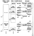
- FIG. 2 is a diagram illustrating a relationship between internal processing of the in-vehicle camera device 100 and control communication with the external device 500 in the first embodiment.
- An example of the internal processing of the in-vehicle camera device 100 and communication of control information (control communication) between the in-vehicle camera device 100 and the external device 500 according to the first embodiment of the present invention will be described with reference to FIG.
- the in-vehicle camera device 100 sequentially outputs image frames 210 and 220 based on the image signal 800.
- a vertical synchronization period 201 exists between the image frames 210 and 220.
- the in-vehicle camera device 100 internally performs image processing according to the image frame. Since the internal processing of the in-vehicle camera device 100 is performed in units of the entire frame, the processing is performed on the image one frame before.
- the normal processing is realized by the cooperative operation of the image processing circuit A120 and the microcomputer A140, and the interrupt processing is handled by using the interrupt execution function of the microcomputer A140.
- the cooperative operation of the image processing circuit A120 and the microcomputer A140 is realized by instructing the microcomputer A140 to start an image processing function to be executed by the image processing circuit A120 at a necessary timing.
- Processing A230 exposure correction
- processing B240 disortion correction
- processing C250 object recognition
- control information associated with control communication is exchanged. Note that these processes are examples, and normal processes can be added / deleted / changed by the function of the in-vehicle camera device 100. In the interrupt process, processes other than those shown in FIG. 2 may be performed.
- Process A230 is a process for correcting sensitivity variations of the image sensor module 110 and sensitivity variations due to pixels.
- process B240 disortion correction
- process C250 object recognition
- an object is detected from the image by image recognition processing, and the three-dimensional estimated position of the object is calculated.
- an edge detection process and a parallax image generation process are also performed first as necessary.
- the external device 500 outputs a communication request signal serving as a command for designating a communication operation at an appropriate timing based on the synchronization information included in the image signal 800 output from the in-vehicle camera device 100.
- the external apparatus 500 outputs the communication request B360 at a timing in time for the start of the process B240, and subsequently outputs the process B setting 361 for setting the operation of the process B240 to the in-vehicle camera apparatus 100.
- the external device 500 After completion of the process A230 and at a timing in time for the start of the process C, the external device 500 issues a communication request aC350, and subsequently outputs a process C setting 351 for setting the operation of the process C250 to the in-vehicle camera apparatus 100.
- the processing time for processing the communication request instruction in the in-vehicle camera device 100 if it can be ensured that the collection of data necessary for communication of the processing A result 315 is completed after the processing A230 is completed, the processing before the processing A230 is completed.
- the output of the communication request aC350 may be started from the timing.
- the result acquisition of the process B240 is the same, and the external apparatus 500 issues the communication request b365 at a timing at which it can be guaranteed that the in-vehicle camera device 100 starts collecting data necessary for the communication of the process B result 325 after the completion of the process B240. Output.
- the processing result necessary for communication is collected by the communication processing 290 of the in-vehicle camera device 100, and the control signal communication unit B150 automatically Set so that the processing result can be output.
- the external device 500 outputs a communication request to the in-vehicle camera device 100 via the control signal 820 in response to the timing when the in-vehicle camera device 100 can output the processing result, and the in-vehicle camera device 100 performs processing corresponding to the communication request.
- the process A result 315 is transmitted to the communication request aC350
- the process B result 325 is transmitted to the external apparatus 500 for the communication request b365.
- the in-vehicle camera apparatus 100 processes the communication request after the process C250 is completed, and the next frame The data is output from the external device 500 at a timing in time for the setting of the process A230.
- a function for issuing a request for performing only the result acquisition of the process A230 is added instead of issuing a request for both the setting to the vehicle-mounted camera device 100 and the result acquisition of the internal processing of the vehicle-mounted camera device 100 as in the communication request aC350.
- a communication request for performing only the process A setting 356 is prepared instead of the communication request cA355, and a communication request for acquiring only the process A result 315 is prepared instead of the communication request aC350. It can also be used.
- a loop correction process is performed in which a brightness correction value is provisionally set for the process A230 and the setting value is updated based on the brightness unevenness of the image acquired via the image signal 800. Further, statistical information (maximum luminance, minimum luminance, luminance distribution tendency, etc.) acquired in the image processing of the in-vehicle camera device 100 in the process A230 is acquired as a result of the process A230, and is used for setting value update control and adjustment end determination. To do.
- the adjustment processing for distortion correction is the same, and it is possible to prepare and use a communication request for performing only setting and result acquisition for the processing B240.
- an in-vehicle camera device 100 captures an image printed with a certain pattern, obtains a provisional distortion correction value from the difference between the image acquired via the image signal 800 and the ideal image, and sets the process B240. Perform loop processing to update the value.
- the statistical information acquired in the image processing of the in-vehicle camera device 100 in the process B240 is also used as a reference for the update control of the set value and the adjustment end determination. However, if the image processing result of the in-vehicle camera device 100 in process B240 is unnecessary, a communication request for acquiring the process B result 325 is also unnecessary.
- the in-vehicle camera device 100 may have different frame output start timing and internal processing start timing.
- the in-vehicle camera device 100 can communicate a control signal at a timing independent of the reference signal of the image signal output from the image signal transmission unit 130.
- a reference timing in the timing generation unit 560 of the external device 500, it is possible to deal with the in-vehicle camera device 100 in which the frame timing and the internal processing timing are different.
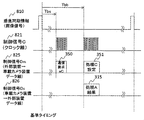
- FIG. 3 is an explanatory diagram of an example of timing when the external device 500 performs communication using the control signal with the in-vehicle camera device 100 in the first embodiment.
- each internal process of the in-vehicle camera device 100 is controlled to be executed within a certain time fluctuation Tf in order to realize a real-time process.
- the allowable time fluctuation Tf is the fluctuation time of the process of the microcomputer A140, and fluctuates around the dotted line between the processes A and B and the dotted line between the processes B and C shown in the figure.
- the communication timing is set by configuring the image processing circuit A120 of the in-vehicle camera device 100 to execute a specific process for a predetermined time, or performing an execution abort process of the software process executed by the microcomputer A140. That is, it is determined that the process A230 ends before the time Tai and before Taa from the reference timing (reference timing) determined based on the image frame, and the process B240 ends after the time Tbi and before Tba. For other processes, the same restriction is imposed on the end timing.
- the external device 500 sets the timing generation unit 560 so that necessary control communication can be performed at a target timing in advance. That is, the timing Tas for performing the communication request B and the process B setting 362 is set to a timing earlier than the time Tai (the end time of the process A). The timing Tbs for performing the communication request aC and the processing C setting 352 is set to a timing at which the in-vehicle camera device 100 processes the communication request after Taa and before Tbi.
- the timing Tbr at which the external device 500 fetches the processing A result 315 from the in-vehicle camera device 100 can process the communication request by the communication processing 290 on the in-vehicle camera device 100 side, and the result of the processing A230 can be transmitted to the external device 500 In order to secure the time required to become the time, the timing with which the time is separated from Tbs is set.
- FIG. 4 is a time chart when a control signal is transmitted and received between the in-vehicle camera device 100 and the external device 500 in the first embodiment, and the external device 500 sets a value for the internal processing of the in-vehicle camera device 100.
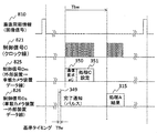
- 5 and 6 are control signal time charts when the external apparatus 500 acquires the internal processing result of the in-vehicle camera apparatus 100.
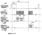
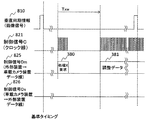
- the control signal 820 includes a control signal C821 serving as a clock for data communication, a control signal Dm825 that is a data signal communicated from the external device 500 to the in-vehicle camera device 100, and an external device from the in-vehicle camera device 100.
- the control signal Ds826 is a data signal to be communicated to 500.
- the data communication clock is always output from the external device 500.
- the vertical synchronization information 810 is information included in the image signal 800, and a portion indicating the vertical synchronization period 201 is described as an H state (high level state) for convenience.
- FIG. 4 is a diagram showing communication related to the communication request B 360 shown in FIG. 2 as an example in which the external device 500 sets a value for the internal processing of the in-vehicle camera device 100.
- a clock is output from the external device 500 to the control signal C821 after the lapse of Tas from the reference timing, which is the falling time of the vertical synchronization period, and the bit string indicating the communication request B360 and the processing B setting 361 are synchronized with this clock.
- the corresponding bit string is output to the control signal Dm825.
- FIG. 5 is a diagram illustrating communication related to the communication request aC350 as an example in which the external device 500 sets a value for the internal processing of the in-vehicle camera device 100 and acquires a result from the internal processing of the in-vehicle camera device 100.
- a clock is output from the external device 500 to the control signal C821 after the elapse of Tbs time from the reference timing which is the falling time of the vertical synchronization period, and the bit string indicating the communication request aC350 and the processing C setting 351 in accordance with this clock. Is output to the control signal Dm825.
- the in-vehicle camera apparatus 100 outputs a bit string corresponding to the process A result 315 to the control signal Ds826.
- FIG. 6 is a diagram illustrating communication related to the communication request B 360 as an example in which the external device 500 acquires the result of the internal processing of the in-vehicle camera device 100.
- Tcs and Tcr are determined based on the fluctuation range of the end time of the process C250 based on the same concept as the communication request aC350.
- a clock is output from the external device 500 to the control signal C821 after the elapse of Tcs time from the reference timing which is the falling time of the vertical synchronization period, and a bit string indicating the communication request b365 is output to the control signal Dm825 in accordance with this clock.
- the in-vehicle camera apparatus 100 outputs a bit string corresponding to the process B result 325 to the control signal Ds826.
- control signal 820 described above is an example, and it is only necessary that other configurations can realize the same function.
- bit length corresponding to the communication request, the bit length used for setting data communication, and the bit length used for processing result communication may be changed according to the required data amount.
- the bit length of the communication request is fixed, the bit length of the setting data and the bit length of the processing result can be uniquely determined from the content of the communication request, and there is a difference between the in-vehicle camera device 100 and the external device 500. It is necessary to prevent it from occurring.
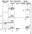
- FIG. 7 is a diagram illustrating an example of a relationship between in-vehicle camera internal processing and control communication when the external apparatus 500 according to the first embodiment writes adjustment data to the in-vehicle camera apparatus 100.
- the adjustment data 381 needs to be written with parameters (brightness correction value, distortion correction value) for each pixel or every several to several tens of pixels, and has a large data amount and a low communication speed control signal.
- parameters (brightness correction value, distortion correction value) for each pixel or every several to several tens of pixels, and has a large data amount and a low communication speed control signal.
- 820 communication may not be completed within one frame. Therefore, a communication mode is prepared for communication using the control signal 820 at an independent timing regardless of the timing of the image frame.
- the external device 500 In order to write the adjustment data 381 to the in-vehicle camera device 100, the external device 500 outputs a process X request 380 using the control signal 820.
- the in-vehicle camera apparatus 100 that has received the process X request 380 performs a process corresponding to the process X request 380 in the communication process 290, and sets a flag for shifting the normal process of the in-vehicle camera apparatus 100 to the process X280 (writing adjustment information).
- the in-vehicle camera apparatus 100 confirms the flag at the end of the process A230 and shifts the normal process to the process X280.
- the external device 500 starts outputting the adjustment data 381, and the in-vehicle camera device 100 writes the adjustment data received in the processing X280 into the flash memory in the microcomputer A140.
- the external device 500 receives the control signal C821 every time constant data transfer is performed when writing to the RAM of the microcomputer A140 or transferring the adjustment data 381. This can be done by temporarily suspending the clock to secure the time for writing to the flash memory.
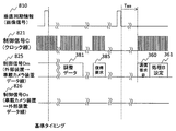
- FIG. 8 is a time chart of control signals when the external apparatus 500 transfers the processing X request and adjustment data to the in-vehicle camera apparatus 100 in the first embodiment.
- a clock is output from the external apparatus 500 to the control signal C821 at an arbitrary timing when other communication is not performed by the control signal 820.
- a bit string corresponding to the processing X request 380 is output to the control signal Dm825 in accordance with this clock.
- the external device 500 outputs the bit string of the processing X request 380, and then outputs the clock to the control signal C821 again after the lapse of Txw time from the start of the processing X request, and outputs the bit string corresponding to the adjustment data 381 according to this clock.
- the transfer of the adjustment data 381 can be continued regardless of the output timing of the vertical synchronization information of the vertical synchronization information 810.
- FIG. 9 is a diagram illustrating the relationship between the in-vehicle camera internal processing and control communication when the in-vehicle camera device 100 is returned to the operation synchronized with the image frame after the adjustment data 381 is transferred.
- the in-vehicle camera device 100 shifts to a process Y285 (waiting for instruction) state after the reception of the adjustment data 381 is completed.
- a process Z289 waiting for mode transition.
- the vehicle camera apparatus 100 waits for the completion of the vertical synchronization period 201 (specific timing), and then proceeds to process A (exposure correction) 230, which is a normal process state.
- FIG. 10 is a diagram illustrating the operation of each signal line constituting the control signal 820 when the in-vehicle camera device 100 shifts from the process X280 to the normal process state.
- the external device 500 stops the clock output to the control signal C821.
- the external device 500 wants to shift the in-vehicle camera device 100 to the normal processing state again, it outputs a clock to the control signal C821 at an arbitrary timing, and outputs a bit string corresponding to the return request 385 to the control signal Dm825 in accordance with the clock.
- the next vertical synchronization information 810 waits for the timing to be released, and the in-vehicle camera device 100 and the external device 500 shift to the normal processing state (processing state synchronized with the image frame).
- the image frame time may vary depending on the frame.
- the external processing device 500 issues a communication request to acquire information on the frame type corresponding to the frame time of the next image frame, and the frame is similar to the procedure for acquiring other processing results. It is also possible to acquire the type result and change the next communication request issue timing (Tas, Tbs, Tbr, etc.) to the timing corresponding to the frame type based on this information.
- the in-vehicle camera device 100 and the external device 500 are separated.
- the external device 500 uses the video signal output from the in-vehicle camera device 100 as a reference timing, and the processing result (exposure) of the in-vehicle camera device 100 Processing, distortion correction processing, object recognition processing) information is output to the in-vehicle camera apparatus 100, and the in-vehicle camera apparatus 100 transmits the processing result information to the external apparatus 500 by an interrupt process different from the normal process.
- the adjustment data 381 is output from the external device 500 to the in-vehicle camera device 100, and the mutual communication of control information such as the request signal, processing result information, and adjustment data between the in-vehicle camera device 100 and the external device is vertical synchronization. It is configured so that it can be executed not only in the period 201 but also in the image frame times 210 and 220.
- the control signal can be separated from the image signal even when the communication of the control signal operates at the timing based on the video signal, and even if the image has a high resolution or a high frame rate,
- the in-vehicle camera device 100 and the in-vehicle camera adjustment device 500 that can use a low-cost integrated circuit such as an inexpensive FPGA without complicating a high-speed circuit for processing a system signal can be realized.
- an in-vehicle camera adjustment system (100, 500) in which the in-vehicle camera device 100 and the in-vehicle camera adjustment device 500 are combined can be realized.
- the communication timing of the control information can be adjusted by the in-vehicle camera adjustment device 500 on the device side to which the in-vehicle camera device 100 is connected, it is also used for checking the internal state of the in-vehicle camera device 100 at a specific timing. This can be applied to debugging of the in-vehicle camera device 100.
- the second embodiment of the present invention is different from the first embodiment in the procedure in the case where a communication request for simultaneously performing setting and result reading from the external device 500 to the in-vehicle camera device 100 and the process X280 is performed.
- the second embodiment has the same configuration as the example shown in FIG.
- FIG. 11 is a diagram illustrating the relationship between the internal processing of the in-vehicle camera device 100 and the control communication between the external device 500 in the second embodiment
- FIG. 12 illustrates the relationship between the in-vehicle camera device 100 and the external device 500 in the second embodiment. It is a time chart of control signal transmission / reception.
- the setting and result acquisition for the in-vehicle camera device 100 are simultaneously performed from the external device 500 following the communication request aC350 and the communication request cA355.
- FIG. 12 shows the operation of each signal line of the control signal 820 corresponding to the communication request aC350 of FIG.
- a clock is output from the external device 500 to the control signal C821 after the elapse of Tbs time from the reference timing which is the fall of the vertical synchronization signal 810, and a bit string indicating the communication request aC350 is output to the control signal Dm825 in accordance with this clock. Is done.
- the clock is output again from the external device 500 to the control signal C821 after the time Tbb has elapsed from the reference timing.
- the external apparatus 500 In synchronization with this clock, the external apparatus 500 outputs a bit string corresponding to the process C setting 351 to the control signal Dm825, and the in-vehicle camera apparatus 100 outputs a bit string corresponding to the process A result 315 to the control signal Ds826.
- FIG. 13 is a diagram illustrating an example of a relationship between in-vehicle camera internal processing and control communication when the external apparatus 500 according to the second embodiment writes adjustment data to the in-vehicle camera apparatus 100.
- FIG. 14 is a time chart of control signals when the external apparatus 500 transfers the processing X request and adjustment data to the in-vehicle camera apparatus 100 in the second embodiment.
- FIG. 13 shows the relationship between the in-vehicle camera internal processing and control communication.
- Polling is performed by outputting the status confirmation 387 from the external device 500 to the control signal 820, and the in-vehicle camera device 100 responds to the status NG 345 or the status OK 346 via the control signal 820.
- FIG. 14 shows the operation of each signal line of the control signal 820 corresponding to the communication procedure of FIG.
- the external device 500 outputs a clock to the control signal C821 and outputs a bit string corresponding to the processing X request 380 to the control signal Dm825.
- the clock is again output to the control signal C821, and the bit string corresponding to the state confirmation 387 is set to the control signal Dm825. Output to.
- the output of the state confirmation 387 is performed at the interval Tpw until the state OK 346 is received from the in-vehicle camera device 100.
- the clock output to the control signal C821 is stopped.
- the external device 500 After the status confirmation 387 is output, the external device 500 outputs a clock to the control signal C821 again to ensure the time required for the in-vehicle camera device 100 to prepare the response data, and the external device 500 outputs a clock to the control signal C821 to state NG345. Alternatively, a bit string corresponding to the state OK 346 is received.
- the external device 500 When the external device 500 receives the bit string corresponding to the state OK 346, the external device 500 starts transmitting the adjustment data 381 to the in-vehicle camera device 100 together with the clock.
- the method of polling the in-vehicle camera device 100 by the external device 500 and confirming the state of the in-vehicle camera device 100 is not limited to confirming that the process has shifted to the process X280, but is assumed inside the in-vehicle camera device 100. It can also be applied to confirm whether or not For example, if a function of process A execution status confirmation for confirming the execution of process A230 is prepared for status confirmation, it is possible to detect whether or not process A230 is being executed. This can be used to confirm whether the control communication assumed between the apparatuses 100 is being performed.
- the same effect as in the first embodiment can be obtained, and the time required for a communication request from the external device 500 to the in-vehicle camera device 100 can be shortened.
- the third embodiment of the present invention is an example in which the timing for issuing a communication request from the external device 500 to the in-vehicle camera 100 is different from the first embodiment.
- Example 3 is also the same configuration as the example shown in FIG.
- the allowable range of fluctuation of the execution time of each process performed inside the in-vehicle camera device 100 is large, and a communication request is issued from the external device 500 after a specific time has elapsed from the reference timing based on the image signal 800.
- a communication request is issued from the external device 500 after a specific time has elapsed from the reference timing based on the image signal 800.
- Example 3 will be described with reference to FIGS.
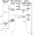
- FIG. 15 is a diagram illustrating the relationship between the internal processing of the in-vehicle camera device 100 and the control communication with the external device 500 in the third embodiment.
- the third embodiment is different from the first embodiment in that a completion notification 349 is transmitted from the control signal communication unit B150 of the in-vehicle camera device 100 to the external device 500.
- the external device 500 can determine the timing at which the next communication request is output by receiving the completion notification 349.
- FIG. 16 is an explanatory diagram of an example of timing when the external apparatus 500 performs communication using the control signal with the in-vehicle camera apparatus 100 in the third embodiment. Signals corresponding to the process A result 315 in FIG. Timing is shown.
- the communication request B and the process B setting 362 are output from the external device 500 to the in-vehicle camera device 100 after a lapse of Tas time from the reference timing because the range of fluctuation of the processing time of the processing A230 is kept constant.
- the communication request aC and the process C setting 352 need to consider the processing time fluctuation of the process B240 in addition to the processing time fluctuation of the process A230, and it is difficult to issue a communication request from the external device 500 at a specific timing.
- the communication request aC and the processing C setting 352 are issued, so that control communication is performed at an appropriate timing according to the progress of the processing of the in-vehicle camera device 100.
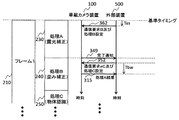
- FIG. 17 is a control signal time chart when the external device 500 acquires the processing result of the image processing circuit A120 of the in-vehicle camera device 100, and the operation of each signal line of the control signal 820 related to the communication request aC350 of FIG. Indicates.
- the in-vehicle camera device 100 outputs a pulse indicating the completion notification 349 to the control signal Ds826 when the clock of the control signal C821 is stopped.
- the pulse width Tfw of the completion notification 349 is set to three cycles of the clock carried on the control signal C821, and the control signal is obtained by allowing the external device 500 to continuously sample twice at the normal sampling rate of communication performed by the control signal 820.
- the completion notification 349 can be stably acquired while filtering the short-time noise on the Ds 826.
- the external device 500 waits for each internal process of the in-vehicle camera device 100 and issues the next communication request, there is no collision with the normal communication of the control signal Ds826 (communication synchronized with the clock of the control signal C821).
- the in-vehicle camera device 100 masks the output of the completion notification 349 and prioritizes communication corresponding to the clock.
- the communication procedure shown in the second embodiment is performed when communicating the setting or processing result corresponding to the communication request from the external device 500.
- the bit string indicating the state of the in-vehicle camera device 100 is always included in the bit string communicated by the control signal Ds 826 so that the external device 500 can grasp the processing state of the in-vehicle camera device 100 through normal communication.
- communication is performed according to the procedure shown in the first embodiment except that the completion notification 349 is used. Instead, communication may be performed according to the procedure shown in the second embodiment.
- the same effects as in the first embodiment can be obtained, and the allowable range of fluctuation of the execution time of each process performed by the in-vehicle camera device 100 is large, so that targeted setting and result acquisition are difficult. Even in this case, the control communication can be performed at an appropriate timing.
- FIG. 18 is a schematic configuration diagram of the in-vehicle camera device 100A according to the fourth embodiment of the present invention, and includes in-vehicle camera units 115A and 115B and an image processing unit 505.
- the in-vehicle camera device 100 is divided into in-vehicle camera units 115A and 115B, and the communication of the control signal 820 between the in-vehicle camera units 115A and 115B and the image processing unit 505 is performed from the first to the embodiments.
- This is an example in which any one of the communication procedures of 3 is used.
- a plurality of in-vehicle camera units 115A and 115B can be connected to one image processing unit 505.
- the on-vehicle camera units 115 ⁇ / b> A and 115 ⁇ / b> B are units mainly for imaging, and have a light image processing and a mutual communication function with the image processing unit 505.
- the image processing unit 505 controls the in-vehicle camera units 115A and 115B via control signals 820A and 820B.
- the image processing unit 505 performs image recognition processing based on the image data acquired from the in-vehicle camera units 115A and 115B.
- the outputs of the image sensor modules 110A and 110B are input to the image processing circuit C135, and after performing simple image processing (calculation of statistical information such as average luminance related to exposure), the image The image signals 800A and 800B are output via the signal transmission unit 130.
- the in-vehicle camera units 115A and 115B use the control signal communication unit F155 to receive communication requests that are the control signals 820A and 820B from the image processing unit 505, set the operation of the image processing circuit C135, and the image sensor
- the operation timing and exposure control parameters of the modules 110A and 110B are set, and information obtained by the image processing circuit C135 is returned to the image processing unit 505 in accordance with a communication request from the image processing unit 505.
- FIG. 19 is a diagram illustrating the relationship between the control communication between the in-vehicle camera units 115A and 115B of Example 4 and the image processing unit 505 and the internal processing of the in-vehicle camera unit 505.
- the in-vehicle camera units 115 ⁇ / b> A and 115 ⁇ / b> B output a completion notification 349 when the process H ⁇ b> 760 (exposure statistics) is completed.
- the image processing unit 505 receives the completion notification 349 and outputs a communication request h 710, and the in-vehicle camera units 115 A and 115 B respond with the communication processing 290 and return a processing H result 712 to the image processing unit 505.
- the image recognition unit 505 outputs data corresponding to the communication request I720 and the subsequent processing I setting 722 using the synchronization information included in the image signal 800A or 800B from any one of the in-vehicle camera units 115A and 115B as a reference timing.
- processing I770 exposure start timing correction
- the image processing unit 505 starts exposure of the next frame based on the clock edge output to the control signal C821 of the control signals 820A and 820B and the waiting time until the start of exposure included in the data of the process I setting 722. Adjust the time.
- the in-vehicle camera units 115A and 115B acquire a left image and a right image in stereo view, it is necessary to match the exposure timing on the left and right, and thus the process I770 is necessary.
- the completion notification 349 is used, so that the control signals 820A and 820B are communicated according to the procedure shown in the third embodiment.
- the timing of the communication request h710 can be determined by the elapsed time from the reference time determined from the image signal 800, so the first or second embodiment. It is conceivable to cope with the procedure shown in.
- the control signal can be separated from the image signal even when the communication of the control signal operates at the timing based on the video signal. Even in this case, there is no complication of a high-speed circuit for processing an image signal, and a low-cost integrated circuit such as an inexpensive FPGA can be used.
- the in-vehicle camera units 115A and 115B and the image processing unit 505 The in-vehicle camera device 100A can be realized.
- the present invention it is possible to synchronize the exposure timing of the in-vehicle camera units 115A and 115B by utilizing that the communication timing of the control information can be adjusted to the timing based on the video signal in the image processing unit 505. It is also possible to perform control.
- Process Y (Waiting for instruction), 289 ... Process Z (Waiting for mode transition), 290 ... Communication processing, 315 ... Processing A 325 ... Process B result 335 ... Result 345 ... G 346 ... K 349 ... Completion notification 350 ... Communication request aC 351 ... Process C setting 352: Communication request aC and process C setting, 355 ... Communication request cA, 356 ... Process A setting, 360 ... Communication request B, 361 ... Process B setting, 362 ... Communication Request B and processing B setting, 380 ... processing X request, 381 ... adjustment data, 385 ... return request, 387 ... status check, 500 ... external device (vehicle camera adjustment device), 530 ...
Landscapes
- Engineering & Computer Science (AREA)
- Multimedia (AREA)
- Signal Processing (AREA)
- Physics & Mathematics (AREA)
- General Physics & Mathematics (AREA)
- Closed-Circuit Television Systems (AREA)
- Studio Devices (AREA)
Abstract
本発明は、画像が高解像度の場合や高フレームレートの場合であっても、画像系の信号を処理する高速回路の複雑化を伴うことが無く、安価なFPGA等の低コスト集積回路を利用可能な車載カメラ装置及び車載カメラ調整装置を実現する。本発明は、外部装置500(車載カメラ調整装置など)は車載カメラ装置100から出力された映像信号を基準タイミングとして車載カメラ装置100の処理結果(露光処理等)情報を出力するように要求信号を車載カメラ装置100に出力する。車載カメラ装置100は通常処理とは異なる割り込み処理により処理結果情報を外部装置500に出力し、調整データ381を外部装置500から車載カメラ装置100に出力する。車載カメラ装置100と外部装置と間の要求信号、処理結果情報、調整データ等の制御情報の相互通信は垂直同期期間201のみならず、画像フレーム時間210、220にも実行することが可能となるように構成される。
Description
本発明は、自動車に搭載する車載カメラ装置、車載カメラ調整装置及び車載カメラ調整システムに関する。
近年、車載安全装置や運転補助装置の外界認識センサとして車載カメラが用いられることがある。このような車載カメラは撮影した画像を処理することで、車両の外界の障害物や先行車、道路情報などを認識する。この認識結果に基づき車両を適切に制御することで、予防安全や運転補助を実現している。
車両制御に認識結果を用いるには、認識した物体の位置を正確に検出する必要がある。
そこで、車載カメラの製造公差を調整する仕組みや、認識結果を評価する仕組みを考慮する必要があり、調整や評価に必要となる制御情報の通信が車載カメラに必要となっている。
そこで、車載カメラの製造公差を調整する仕組みや、認識結果を評価する仕組みを考慮する必要があり、調整や評価に必要となる制御情報の通信が車載カメラに必要となっている。
車載カメラによる画像処理は、画像1フレーム単位での処理を基本とするので、調整や評価、画像の撮像制御や認識処理の制御情報は、その全部あるいは一部を画像の各フレームに同期させて通信を行うことが通常である。
画像の各フレームに同期して制御情報の通信を行う装置としては、特許文献1に示された装置がある。特許文献1には、画像信号のブランキング期間を用いて画像信号に情報を重畳することが述べられており、情報は画像に同期して伝送される。
しかしながら、特に画像が高解像度の場合や高フレームレートの場合、画像信号に制御信号を重畳すると、画像系を取り扱う高速回路に制御情報を取り扱う回路の一部を組み込む必要が生じ、高速回路が複雑化することになる。
この結果、高速回路部分の回路遅延増加や高速回路の最適化の影響などで、取り扱う機能以上に論理の増大を招き、あるいは必要動作周波数での動作が困難になり、安価なFPGA(Field-Programmable Gate Array)など低コスト集積回路の利用ができない場合があるという課題があった。
本発明の目的は、高解像度、高フレームレート等の画像を取り扱うことが原因で、画像系の信号を処理する回路が高速となっても、当該高速回路が複雑となることを抑制し、安価なFPGA等の低コスト集積回路を利用可能な車載カメラ装置、車載カメラ調整装置及び車載カメラ調整システムを実現することである。
上記目的を達成するため、本発明は次のように構成される。
(1)車載カメラ装置において、画像を撮像する画像撮像部と、上記画像撮像部が撮像した画像の処理を行う画像処理部と、上記画像処理部が処理した画像情報を出力する画像信号送出部と、上記画像信号送出部が出力した画像情報に基づき、上記画像処理部が行う画像処理に関する情報を有する制御情報を通信する制御信号通信部とを備え、上記制御信号通信部は、上記画像信号送出部から出力される画像情報に含まれる画像フレーム内の基準信号に基づいて予め設定した時間後に上記制御情報を通信し、上記画像処理部は、上記制御情報に応答して画像処理を行う。
(2)車載カメラ装置を調整する車載カメラ調整装置であって、上記車載カメラ装置から画像情報を受信する画像信号受信部と、上記受信した画像情報に基づいて、制御情報を生成する信号処理部と、上記受信した画像情報に同期して上記車載カメラ装置と制御情報を通信する制御信号通信部とを備え、上記制御信号通信部は、上記画像信号受信部が受信した上記画情報に含まれる画像フレーム内の基準信号に基いて所定時間経過後に、上記車載カメラ装置に制御情報を出力し、上記所定時間は、上記車載カメラ装置が画像情報を処理するのに要する時間に基づいて設定される。
(3)車載カメラ装置及び車載カメラ調整装置を有する車載カメラ調整システムにおいて、上記車載カメラ調整装置は、上記車載カメラ装置から画像情報を受信する画像信号受信部と、上記画像情報に同期して制御情報を上記車載カメラ装置に送信する制御信号通信部とを有し、上記車載カメラ調整装置の上記制御信号通信部は、上記画像信号受信部で上記画像情報に含まれる画像フレーム内の基準信号を受信してから所定時間経過後に、上記車載カメラ装置に対して上記制御情報を前記制御信号へ出力し、上記記所定時間は、上記車載カメラ装置が上記画像情報を処理するのに要する時間に基づいて設定される。
(4)車載カメラ装置において、撮像機能を有する車載カメラユニットと、上記車載カメラユニットの画像情報出力を受信し画像認識処理を行う画像処理ユニットと、が分離されている構成では、上記車載カメラユニットと上記画像処理ユニットは制御情報を相互通信し、上記画像処理ユニットは、上記車載カメラユニットから画像情報を受信する画像信号受信部と、上記画像情報に同期して上記制御情報を送信する制御信号通信部とを有し、上記制御信号通信部は、上記画像信号受信部で受信した上記画像情報に含まれる画像フレーム内の基準信号を受信してから所定時間経過後に、上記車載カメラユニットに対して上記制御情報を出力し、上記所定時間は、上記車載カメラユニットが画像情報を処理するのに要する時間に基づいて設定される。
本発明によれば、画像が高解像度の場合や高フレームレートの場合であっても、画像系の信号を処理する高速回路の複雑化を伴うことが無く、安価なFPGA等の低コスト集積回路を利用可能な車載カメラ装置、車載カメラ調整装置及び車載カメラ調整システムを実現することができる。
以下、本発明の実施形態について添付図面を参照して説明する。
(実施例1)
図1は、本発明の実施例1による車載カメラ装置及び車載カメラ調整装置の概略構成図である。
図1は、本発明の実施例1による車載カメラ装置及び車載カメラ調整装置の概略構成図である。
図1において、車載カメラ装置100と、車載カメラ調整装置である外部装置500とにより車載カメラ調整システムが構成される。外部装置500は車載カメラ装置100の調整に用いる装置、あるいは動作情報の取得やデバッグに用いる装置などに相当する。
車載カメラ装置100は、画像を撮像し電気信号に変換する2つの画像センサモジュール(画像撮像部)110A、110Bと、画像処理のアクセラレータとして機能する画像処理回路(画像処理部)A120と、画像処理回路A120の制御やソフトウェアによる画像処理、及び車載カメラ装置100の全体制御を行うマイコンA140と、撮影した画像や画像処理回路A120で処理した画像を出力するインタフェースとなる画像信号送出部130と、マイコンA140が必要とする制御情報の通信インタフェースとなる制御信号通信部150とを備える。
画像処理回路A120は、マイコンA140で処理すると効率が悪く処理内容に対して実行時間を要する処理、例えば、画像の露光補正や歪み補正、エッジ抽出処理を行う。図1に示す車載カメラ装置100は、ステレオ視により対象物までの距離を検出する機能を有するカメラ装置であるため、画像センサモジュール110を2個有し、画像処理回路A120には左右画像から各画素グループ(画素を縦横数ピクセル単位で束ねたもの)に対する視差の大きさを検出する機能(視差画像生成機能)も有する。
マイコンA140は、CAN(Controller Area Network)に接続されており、車両に存在する他の制御装置(図示せず)とCAN信号で相互通信することができる。
外部装置500は、車載カメラ装置100から出力された画像信号800を受信するインタフェースとなる画像信号受信部A530と、車載カメラ装置100と制御信号820を相互通信するインタフェースとなる制御信号通信部A550と、画像信号800を分析処理し車載カメラ装置100から取得した制御情報も用いて車載カメラ装置100に出力する制御情報(画像処理回路A120が行う画像の露光補正や歪み補正、エッジ抽出処理等の調整に関する情報)を生成する信号処理部540と、画像信号800に含まれる同期情報(垂直同期信号や水平同期信号、あるいは画像信号800内の特定のデータパターンなど)を元に、画像の1フレーム内の基準となるタイミングを検出し、そのタイミングから特定の時間経過後に信号を出力するタイミング生成部560と、タイミング生成部560からの信号及び信号処理部540からの指示に従い、制御用のコマンドを生成するコマンド生成部570とを備える。
外部装置500を構成する信号処理部540は専用機器でもパソコンと専用のソフトウェアを組み合わせた構成でも構わない。
以上のような構成とすることで、外部装置500は画像信号800から検出できるタイミングを基準にした画像のフレーム内の特定のタイミングを狙って制御情報の通信を行うことが可能である。
車載カメラ装置100の調整は、車載カメラ装置100の製品としての出荷前等において行行われる。これは、2つの画像センサモジュール110A、110Bにより予め定めた、例えば、いくつかの幾何学模様を撮像し、画像処理回路A120、画像信号送出部130を介して出力された画像信号800を外部装置500が受信し、受信した信号から、車載カメラ装置100の例えば、歪補正やシェーディング補正が必要か否かを判断し、これらの補正が必要な場合は、補正信号を車載カメラ装置100に出力する。車載カメラ装置100は、受信した補正信号に従って、歪補正やシェーディング補正を行う。
本発明は、車載カメラ装置100と、車載カメラ調整装置である外部装置500との間の制御制情の送受信についての技術である。
図2は、実施例1における車載カメラ装置100の内部処理と外部装置500との制御通信の関係を示す図である。図2を用いて本発明の実施例1における車載カメラ装置100の内部処理と車載カメラ装置100と外部装置500との間の制御情報の通信(制御通信)の関係の一例を説明する。
車載カメラ装置100は、画像信号800により順次画像フレーム210、220を出力する。画像フレーム210と220との間には垂直同期期間201が存在する。車載カメラ装置100は、画像フレームに合わせて内部で画像処理を行う。車載カメラ装置100の内部処理はフレーム全体単位で実施するため、1フレーム前の画像に対して処理を行う。
車載カメラ装置100の内部では、順次処理が実行される通常処理と、通常処理に割り込み処理を行う割込処理がある。通常処理は画像処理回路A120とマイコンA140の協調動作により実現し、割込処理はマイコンA140の割り込み実行機能を用いて対応する。
画像処理回路A120とマイコンA140の協調動作は、マイコンA140が主体となって、必要なタイミングで画像処理回路A120の実行すべき画像処理機能を開始するよう指示することで実現する。
車載カメラ装置100の通常処理として、処理A230(露光補正)、処理B240(歪み補正)、処理C250(物体認識)を実行する。割込処理では制御通信に伴う制御情報のやり取りを実施する。尚、これらの処理は一例であり、通常処理は車載カメラ装置100の機能により追加・削除・変更が可能であり、割込処理では図2に示す以外の処理を行っても構わない。
処理A230(露光補正)は画像センサモジュール110の感度ばらつきや画素による感度ばらつきの補正を行う処理である。処理B240(歪み補正)では光学系で発生する画像の変形を補正する。処理C250(物体認識)では画像認識処理により画像の中から物体を検出し、また物体の3次元推定位置を算出する。処理C250では必要に応じて最初にエッジ検出処理や視差画像生成処理も行う。
制御通信では、外部装置500が車載カメラ装置100から出力される画像信号800に含まれる同期情報を元に適切なタイミングで通信動作を指定するコマンドとなる通信要求信号を出力する。外部装置500は、処理B240の開始に間に合うタイミングで通信要求B360を出力し、引き続き処理B240の動作設定をする処理B設定361を車載カメラ装置100に出力する。
処理A230完了後、かつ処理Cの開始に間に合うタイミングで、外部装置500は、通信要求aC350を出し、引き続き処理C250の動作設定をする処理C設定351を車載カメラ装置100に出力する。この際、車載カメラ装置100で通信要求指示を処理する処理時間を考慮し、処理A230完了後に処理A結果315の通信に必要なデータの収集を開始することが保証できれば、処理A230の完了前のタイミングから通信要求aC350の出力を開始しても構わない。
処理B240の結果取得も同様で、処理B240の完了以降に車載カメラ装置100が処理B結果325の通信に必要なデータの収集を開始することを保証できるタイミングで、外部装置500が通信要求b365を出力する。
車載カメラ装置100から処理結果を取得する通信要求、通信要求aC350や通信要求b365などでは、車載カメラ装置100の通信処理290で通信に必要な処理結果を集め、制御信号通信部B150が自動的に処理結果を出力できるように設定する。車載カメラ装置100が処理結果を出力可能になったタイミングを見計らって、外部装置500は制御信号820を介して車載カメラ装置100へ通信要求を出力し、車載カメラ装置100は通信要求に対応した処理結果、すなわち通信要求aC350に対しては処理A結果315、通信要求b365に対しては処理B結果325を外部装置500へ送信する。
通信要求cA355は処理C250の結果を取得し処理A230の設定を行う要求であるため、車載カメラ装置100が、処理C250が完了した以降に車載カメラ装置100が通信要求を処理し、次のフレームの処理A230の設定に間に合うタイミングで外部装置500より出力する。
調整や評価の目的により、一部の制御通信のみを実施しても構わない。また、通信要求aC350のように、車載カメラ装置100への設定と車載カメラ装置100内部処理の結果取得の両方の要求を出す代わりに、処理A230の結果取得のみ実施する要求を出す機能も追加して良い。例えば、露光補正の調整の際には均一の明るさとなっている画像を車載カメラ装置100で撮影しながら、処理A230の設定と結果取得のみを行うことが考えられる。この場合、通信要求cA355の代わりに処理A設定356のみを行うための通信要求を用意し、通信要求aC350の代わり処理A結果315を取得するのみの通信要求を用意して、これらの通信要求を用いることも有り得る。
露光補正の調整処理では、処理A230に対し暫定的に輝度補正値を設定し、画像信号800経由で取得した画像の輝度むらを元に設定値を更新するループ処理を行う。また、処理A230で車載カメラ装置100の画像処理にて取得した統計情報(最高輝度、最低輝度、輝度分布傾向など)を処理A230の結果として取得し、設定値の更新制御や調整終了判定に利用する。
歪み補正の調整処理も同様であり、処理B240に対する設定と結果取得のみを行う通信要求を用意して利用することも有り得る。
歪み補正の調整処理では、一定パターンを印刷した画像を車載カメラ装置100で撮影し、画像信号800経由で取得した画像と理想画像の差分から、暫定的な歪み補正値を求め、処理B240の設定値を更新するループ処理を行う。処理B240で車載カメラ装置100の画像処理にて取得した統計情報も参考にして、設定値の更新制御や調整終了判定に利用する。但し、処理B240の車載カメラ装置100の画像処理結果が不要な場合には、処理B結果325を取得する通信要求も不要となる。
尚、車載カメラ装置100はフレーム出力開始タイミングと内部処理の開始タイミングが異なっていても構わない。
すなわち、車載カメラ装置100は、画像信号送出部130が出力した画像信号の基準信号とは独立したタイミングで制御信号の通信を行うことができる。外部装置500のタイミング生成部560で基準となるタイミングを適切に設定することで、フレームのタイミングと内部処理のタイミングが異なる車載カメラ装置100にも対応可能である。
次に、図3を参照して、外部装置500が車載カメラ装置100と制御信号820を用いた通信を行う際のタイミングを説明する。
図3は、実施例1において、外部装置500が車載カメラ装置100と制御信号を用いた通信を行う際のタイミングの一例の説明図である。
図3において、本実施例1においては、車載カメラ装置100の内部処理それぞれはリアルタイム処理を実現するためにある程度の時間揺らぎTfの範囲内で実行されるように制御する。許容時間揺らぎTfは、マイコンA140の処理の揺らぎ時間であり、図示した処理AとBとの間の点線、処理BとCとの間の点線を中心として揺らぐものである。
通信タイミングの設定は、車載カメラ装置100の画像処理回路A120を一定時間で特定の処理を実行する構成にすることや、マイコンA140で実行するソフト処理の実行打ち切り処理などを行うことで対応する。すなわち、処理A230は画像フレームを元に決定した基準となるタイミング(基準タイミング)から時間Tai以降Taa以前に終了し、処理B240は時間Tbi以降Tba以前に終了することが決められている。他の処理についても終了タイミングに同様の制約をかける。
外部装置500は予め目的のタイミングで必要な制御通信を行えるように、タイミング生成部560の設定を行う。すなわち、通信要求B及び処理B設定362を行うタイミングTasは時間Tai(処理Aの終了時間)より早いタイミングに設定する。通信要求aC及び処理C設定352を行うタイミングTbsは、車載カメラ装置100が通信要求を処理する時刻がTaa以降Tbi以前になるタイミングに設定する。
また、外部装置500が、車載カメラ装置100から処理A結果315を取り込むタイミングTbrは、車載カメラ装置100側で通信処理290により通信要求を処理し、処理A230の結果を外部装置500に対し送信可能となるのに要する時間が確保できるように、Tbsから時間を空けたタイミングを設定する。
画像フレームの垂直同期タイミングを基準とする場合の、制御信号820を構成する各信号線の動作を図4から図6を用いて説明する。
図4は、実施例1における車載カメラ装置100と外部装置500との間で制御信号を送受し、外部装置500が車載カメラ装置100の内部処理に対して値を設定する際のタイムチャートであり、図5及び図6は、車載カメラ装置100の内部処理結果を外部装置500が取得する際の制御信号タイムチャートである。
図4~図6において、制御信号820は、データ通信のクロックとなる制御信号C821と、外部装置500から車載カメラ装置100へ通信するデータ信号である制御信号Dm825と、車載カメラ装置100から外部装置500へ通信するデータ信号である制御信号Ds826で構成する。データ通信のクロックは常に外部装置500から出力する。
垂直同期情報810は、画像信号800に含まれる情報で、垂直同期期間201を示す部分を便宜的にH状態(ハイレベル状態)として記している。
垂直同期情報810は、画像信号800に含まれる情報で、垂直同期期間201を示す部分を便宜的にH状態(ハイレベル状態)として記している。
図4は外部装置500が車載カメラ装置100の内部処理に対して値を設定する例として、図2に示した通信要求B360に関連する通信を示す図である。図4において、垂直同期期間の立下り時間である基準タイミングからTas時間経過後に外部装置500から制御信号C821にクロックが出力され、このクロックに合わせて通信要求B360を示すビット列及び処理B設定361に対応するビット列が制御信号Dm825に出力される。
図5は外部装置500が車載カメラ装置100の内部処理に対して値を設定し、さらに車載カメラ装置100の内部処理から結果を取得する例として通信要求aC350に関連する通信を示す図である。図5において、垂直同期期間の立下り時間である基準タイミングからTbs時間経過後に、外部装置500から制御信号C821にクロックが出力され、このクロックに合わせて通信要求aC350を示すビット列及び処理C設定351に対応するビット列が制御信号Dm825に出力される。一度、制御信号C821のクロックは停止され、基準タイミングからTbr時間経過後に外部装置500から制御信号C821に再びクロックを出力する。このクロックに合わせて車載カメラ装置100は制御信号Ds826に処理A結果315に対応するビット列を出力する。
図6は外部装置500が車載カメラ装置100の内部処理の結果を取得する例として通信要求B360に関連する通信を示す図である。図6において、Tcs、Tcrは、通信要求aC350と同様の考え方で、処理C250の終了時間の揺らぎ範囲を元に決める。
垂直同期期間の立下り時間である基準タイミングからTcs時間経過後に外部装置500から制御信号C821にクロックが出力され、このクロックに合わせて通信要求b365を示すビット列が制御信号Dm825に出力される。一度、制御信号C821のクロックは停止され、基準タイミングからTcr時間経過後に外部装置500から制御信号C821に再びクロックを出力する。このクロックに合わせて車載カメラ装置100は制御信号Ds826に処理B結果325に対応するビット列を出力する。
垂直同期期間の立下り時間である基準タイミングからTcs時間経過後に外部装置500から制御信号C821にクロックが出力され、このクロックに合わせて通信要求b365を示すビット列が制御信号Dm825に出力される。一度、制御信号C821のクロックは停止され、基準タイミングからTcr時間経過後に外部装置500から制御信号C821に再びクロックを出力する。このクロックに合わせて車載カメラ装置100は制御信号Ds826に処理B結果325に対応するビット列を出力する。
なお、上述した制御信号820の構成は一例であり、他の構成でも同様の機能を実現できれば構わない。また、通信要求に対応するビット長や設定データの通信に用いるビット長、処理結果の通信に用いるビット長も必要なデータ量に応じて変更して構わない。但し、通信要求はビット長を固定にして、設定データのビット長や処理結果のビット長は通信要求の内容から一意に決定できるようにして、車載カメラ装置100と外部装置500の間で齟齬が生じないようにする必要がある。
次に、外部装置500を用いて決定した車載カメラ装置100の調整データ381を車載カメラ装置100のマイコンA140に搭載されたフラッシュメモリなどに書き込む際の車載カメラ内部処理と制御通信の関係について図7を用い説明する。
図7は、実施例1における外部装置500が調整データを車載カメラ装置100に書き込む際の車載カメラ内部処理と制御通信の関係の一例を示す図である。
図7において、調整データ381は、各画素あるいは数個から数十個の画素単位ごとにパラメータ(輝度補正値、歪み補正値)を書き込む必要があり、データ量が多く、通信速度の遅い制御信号820では1フレーム内で通信を完了できない可能性がある。そこで、画像フレームのタイミングとは無関係に、独立したタイミングで制御信号820を用いて通信する通信モードを用意して対応する。
調整データ381を車載カメラ装置100に書き込むために、外部装置500は制御信号820を用いて処理X要求380を出力する。処理X要求380を受信した車載カメラ装置100は通信処理290で処理X要求380に対応する処理を行い、車載カメラ装置100の通常処理を処理X280(調整情報書き込み)用に移行するフラグを立てる。車載カメラ装置100は処理A230の区切りに当該フラグを確認し通常処理を処理X280に移行する。
車載カメラ装置100が処理X280に確実に移行する時刻を待ち、外部装置500は調整データ381の出力を開始し、車載カメラ装置100は処理X280で受け取った調整データをマイコンA140内のフラッシュメモリに書き込む。フラッシュメモリの書き込み速度より制御信号820のデータ転送速度が高速な場合は、マイコンA140のRAMに書きこんだり、調整データ381を転送する際に、一定データ転送毎に外部装置500が制御信号C821のクロックを一時停止してフラッシュメモリへの書き込み時間を確保したりして対応する。
次に、図8を用い処理X要求380及び調整データ381の転送に伴う制御信号820を構成する各信号線の動作を説明する。
図8は、実施例1において外部装置500が処理X要求及び調整データを車載カメラ装置100に転送する際の制御信号のタイムチャートである。
図8において、外部装置500より車載カメラ装置100に調整データ381を書き込む際には、他の通信を制御信号820で行っていない任意のタイミングで外部装置500より制御信号C821にクロックを出力し、このクロックに合わせて制御信号Dm825に処理X要求380に対応するビット列を出力する。外部装置500は処理X要求380のビット列を出力後、処理X要求を開始してからTxw時間経過後に再び制御信号C821にクロックを出力し、このクロックに合わせて調整データ381に対応するビット列を出力する。
車載カメラ装置100は処理X280実行中には画像フレームに関係なく動作するため、垂直同期情報810の垂直同期情報の出力タイミングとは関係なく調整データ381の転送を継続できる。
図9は、調整データ381の転送後、車載カメラ装置100を画像フレームに同期した動作に戻す際の車載カメラ内部処理と制御通信の関係を示す図である。
図9において、車載カメラ装置100は調整データ381の受信完了後、処理Y285(指示待ち)状態に移行する。この状態で外部装置500が復帰要求385を制御信号820経由で出力すると、車載カメラ装置100は処理Z289(モード移行待ち)となる。車載カメラ装置100は処理Z289状態になった後、垂直同期期間201の完了(特定のタイミング)を待って、通常の処理状態である処理A(露光補正)230に移行する。
図10は、車載カメラ装置100が処理X280から通常の処理状態へ移行する際の制御信号820を構成する各信号線の動作を示す図である。
図10に示すように、調整データ381の通信完了後、外部装置500は制御信号C821へのクロック出力を停止する。外部装置500は車載カメラ装置100を再度通常の処理状態へ移行させたい場合、任意のタイミングで制御信号C821にクロックを出力し、クロックに合わせて復帰要求385に対応するビット列を制御信号Dm825に出力する。その後、次の垂直同期情報810は解除されるタイミングを待って、車載カメラ装置100及び外部装置500は通常の処理状態(画像フレームに同期した処理状態)へ移行する。
なお、画像フレームに同期した処理状態が垂直同期を基準としない場合は、その基準とするタイミングにて通常の処理状態に移行することも考えられる。
また、外部装置500から車載カメラ装置100内部の処理の途中に通信要求を出し、その時の内部状態を結果として取得することで、車載カメラ装置100の内部で行われる処理のデバッグや処理速度の調査に活用することも考えられる。
さらに、車載カメラ装置100によっては画像フレーム時間が、フレームにより異なる場合がある。このような場合、例えば垂直同期期間201に外部処理装置500が次の画像フレームのフレーム時間に対応するフレームタイプの情報を取得する通信要求を出し、他の処理結果を取得する手順と同様にフレームタイプの結果を取得し、この情報に基づき、次の通信要求発行タイミング(Tas、Tbs、Tbrなど)をフレームタイプに対応するタイミングに変更して対応することも可能である。
外部装置500による車載カメラ装置100の調整が終了すると、車載カメラ装置100と外部装置500とは分離される。
以上のように、本発明の実施例1によれば、外部装置500(車載カメラ調整装置)は、車載カメラ装置100から出力された映像信号を基準タイミングとして、車載カメラ装置100の処理結果(露光処理、歪補正処理、物体認識処理)情報を出力するように要求信号を車載カメラ装置100に出力し、車載カメラ装置100は、通常処理とは異なる割り込み処理により上記処理結果情報を外部装置500に出力し、調整データ381を外部装置500から車載カメラ装置100に出力し、車載カメラ装置100と外部装置と間の上記要求信号、処理結果情報、調整データ等の制御情報の相互通信は、垂直同期期間201のみならず、画像フレーム時間210、220にも実行することが可能となるように構成されている。
したがって、映像信号を基準としたタイミングで動作する制御信号の通信であっても制御信号を画像信号から分離することができ、画像が高解像度の場合や高フレームレートの場合であっても、画像系の信号を処理する高速回路の複雑化を伴うことが無く、安価なFPGA等の低コスト集積回路を利用可能な車載カメラ装置100及び車載カメラ調整装置500を実現することができる。
また、車載カメラ装置100と車載カメラ調整装置500を組み合わせた車載カメラ調整システム(100、500)を実現することができる。
また、制御情報の通信タイミングを、車載カメラ装置100を接続する先の機器側である車載カメラ調整装置500で調整可能となるため、特定のタイミングで車載カメラ装置100の内部の状態確認にも利用でき、車載カメラ装置100のデバッグにも適用することが可能となる。
(実施例2)
次に、本発明の実施例2について説明する。
次に、本発明の実施例2について説明する。
本発明の実施例2は、外部装置500から車載カメラ装置100への設定と結果読み出しを同時に行う通信要求を出した場合の手順、及び処理X280への移行手順が実施例1と異なる。全体構成については、実施例2も図1に示した例と同等の構成であるので、図示及び詳細な説明は省略する。
図11は、実施例2における車載カメラ装置100の内部処理と外部装置500との制御通信の関係を示す図であり、図12は、実施例2における車載カメラ装置100と外部装置500との間の制御信号送受のタイムチャートである。
図11及び図12を参照して、外部装置500から車載カメラ100への設定と結果読み出しを同時に行う通信要求を出した場合の手順が異なる構成を説明する。
図11において、通信要求aC350及び通信要求cA355の後に続く外部装置500から車載カメラ装置100に対する設定と結果取得を同時に行っている。
つまり、通信要求aC350の後、処理A結果315と処理C設定351の通信を同時に行い、通信要求cA355の後、処理C結果335と処理A設定356の通信を同時に行う。
図11の通信要求aC350に対応する制御信号820の各信号線の動作を図12に示す。図12において、垂直同期信号810の立下りである基準タイミングからTbs時間経過後に外部装置500から制御信号C821にクロックが出力され、このクロックに合わせて通信要求aC350を示すビット列が制御信号Dm825に出力される。一度、制御信号C821のクロックは停止され、基準タイミングからTbb時間経過後に外部装置500から制御信号C821に再びクロックを出力する。このクロックに合わせて外部装置500は制御信号Dm825に処理C設定351に対応するビット列を出力し、車載カメラ装置100は制御信号Ds826に処理A結果315に対応するビット列を出力する。
処理C設定351に対応するビット列と処理A結果315に対応するビット列の長さが互いに異なる場合は、制御信号C821に出力するクロックは長いビット長に合わせて出力する。短いビット長のデータを受信した側(車載カメラ装置100または外部装置500)はビット列の最後に付加された余分なデータを無視する。実施例2におけるこの手順では、実施例1に対し処理C351の通信に用いる時間を削減できる利点がある。
図13は、実施例2における外部装置500が調整データを車載カメラ装置100に書き込む際の車載カメラ内部処理と制御通信の関係の一例を示す図である。また、図14は、実施例2において外部装置500が処理X要求及び調整データを車載カメラ装置100に転送する際の制御信号のタイムチャートである。
図13及び図14を用い、処理X280への移行手順を説明する。この手順は実施例1で説明した図8の時間Txwの決定が困難な場合に用いる。
図13は車載カメラ内部処理と制御通信の関係を示しており、外部装置500が処理X要求380を出力した後、車載カメラ装置100が調整データ381を受信可能な状態、すなわち処理X280を実行する状態となったことを、外部装置500から車載カメラ装置100に対しポーリングを行うことで確認する。
ポーリングは外部装置500から状態確認387を制御信号820に出力し、これに対して車載カメラ装置100が状態NG345あるいは状態OK346を制御信号820経由で応答することで行う。
図14は、図13の通信手順に対応する制御信号820の各信号線の動作を示す。図14において、外部装置500は制御信号C821にクロックを出力し、処理X要求380に対応するビット列を制御信号Dm825に出力する。御信号C821にクロックを出力してから、Tpfw時間経過後、状態確認387を出力するために、再び制御信号C821にクロックを出力し、制御信号Dm825に状態確認387に対応するビット列を制御信号Dm825に出力する。
状態確認387の出力は車載カメラ装置100から状態OK346を受信するまで、間隔Tpwで行う。状態確認387の出力が完了したら制御信号C821に出力するクロックを停止する。
状態確認387出力後、車載カメラ装置100が応答データの準備に要する時間を確保するためTp時間経過するのを待ち、外部装置500は再び制御信号C821にクロックを出力し車載カメラ装置100から状態NG345または状態OK346に対応するビット列を受信する。
外部装置500は状態OK346に対応するビット列を受信したら、調整データ381の車載カメラ装置100への送信をクロックと共に開始する。
尚、外部装置500が車載カメラ装置100に対しポーリングを行い、車載カメラ装置100の状態を確認する手法は、処理X280へ移行したことを確認するのに限らず、車載カメラ装置100の内部で想定した状態になっているかの確認にも応用可能である。例えば、状態確認に、処理A230の実行中を確認する処理A実行状態確認という機能を用意すれば、処理A230の実行中であるか否かを検出することも可能となり、外部装置500と車載カメラ装置100の間で想定している制御通信が行われているかの確認に利用することができる。
本発明の実施例2によれば、実施例1と同等な効果を得ることができる他、外部装置500から車載カメラ装置100への通信要求に必要な時間を短縮することができる。
(実施例3)
次に、本発明の実施例3について説明する。
次に、本発明の実施例3について説明する。
本発明の実施例3は、外部装置500から車載カメラ100への通信要求を出すタイミングが実施例1とは異なる例である。全体構成については、実施例3も図1に示した例と同等の構成であるので、図示及び詳細な説明は省略する。
実施例3は、車載カメラ装置100の内部で行われる各処理の実行時間の揺らぎの許容範囲が大きく、画像信号800を基にした基準タイミングから特定時間経過後に外部装置500から通信要求を出すのでは狙った設定や結果取得が困難な場合に対応可能な例である。
本実施例3を図15から図17を用いて説明する。
図15は、実施例3における車載カメラ装置100の内部処理と外部装置500との制御通信の関係を示す図である。図15において、実施例3では、車載カメラ装置100の制御信号通信部B150から完了通知349を外部装置500へ送信する点が実施例1とは異なる。外部装置500は完了通知349を受信することで次の通信要求が出力されるタイミングを判断可能である。
図16は、実施例3において、外部装置500が車載カメラ装置100と制御信号を用いた通信を行う際のタイミングの一例の説明図であり、図15の処理A結果315までに対応する信号のタイミングを示している。
図16において、通信要求B及び処理B設定362は処理A230の処理時間の揺らぎの範囲が一定に収まるので、基準タイミングからTas時間経過後に外部装置500から車載カメラ装置100に出力する。しかし、通信要求aC及び処理C設定352は、処理A230の処理時間揺らぎに加え処理B240の処理時間揺らぎも考慮する必要があり、外部装置500から特定のタイミングで通信要求を出すのが難しい。
そこで、車載カメラ100からの完了通知349を確認した後に、通信要求aC及び処理C設定352を出すことで、車載カメラ装置100の処理の進みに応じて適切なタイミングで制御通信を実施する。
図17は、車載カメラ装置100の画像処理回路A120の処理結果を外部装置500が取得する際の制御信号タイムチャートであり、図15の通信要求aC350に関係する制御信号820の各信号線の動作を示す。
図17において、車載カメラ装置100から主体的に完了通知349が出力されるため、制御信号C821のクロック停止時に車載カメラ装置100は制御信号Ds826に完了通知349を示すパルスを出力する。完了通知349のパルス幅Tfwは制御信号C821に乗せるクロックの3周期分とし、外部装置500が制御信号820で行う通信の通常のサンプリング速度で2回連続してサンプリング可能とすることで、制御信号Ds826に乗る短時間のノイズをフィルタしながら安定して完了通知349を取得できるようにする。
外部装置500が車載カメラ装置100の各内部処理を待って次の通信要求を出す場合、制御信号Ds826の通常の通信(制御信号C821のクロックに同期した通信)との衝突は発生しない。しかし、外部装置500から車載カメラ装置100内部の処理の途中に通信要求を出し、その時の内部状態を結果として取得する場合は衝突の可能性があるため、制御信号C821に外部装置500からクロックが出力されている期間は、車載カメラ装置100は完了通知349の出力をマスクし、クロックに対応する通信を優先する。
この場合、外部装置500は完了通知349の検出ができない場合が発生するため、外部装置500からの通信要求に対応した、設定あるいは処理結果を通信する際に、実施例2で示した通信手順を用いて、車載カメラ装置100の状態を示すビット列を必ず制御信号Ds826で通信するビット列に含め、通常の通信で外部装置500が車載カメラ装置100の処理状態を把握できるようにする。
尚、実施例3では完了通知349を用いる以外は実施例1に示した手順で通信を行うが、代わりに実施例2で示した手順で通信を行うことも考えられる。
本発明の実施例3によれば、実施例1と同様な効果が得られる他、車載カメラ装置100が行う各処理の実行時間の揺らぎの許容範囲が大きく、狙った設定や結果取得が困難な場合であっても、適切なタイミングで制御通信が可能となる効果を有する。
(実施例4)
次に、本発明の実施例4について説明する。
次に、本発明の実施例4について説明する。
図18は、本発明の実施例4による車載カメラ装置100Aの概略構成図であり、車載カメラユニット115Aと115B及び画像処理ユニット505を備える。
本発明の実施例4は、車載カメラ装置100を車載カメラユニット115Aと115Bとに分け、車載カメラユニット115A及び115Bと画像処理ユニット505との間の制御信号820の通信に実施例1から実施例3のいずれかの通信手順を用いた構成とする例である。
図18において、1台の画像処理ユニット505には複数の車載カメラユニット115A、115Bを接続可能である。車載カメラユニット115A及び115Bは撮像を主体とするユニットで、軽い画像処理及び画像処理ユニット505との相互通信機能を持つ。
画像処理ユニット505は車載カメラユニット115A及び115Bの制御を制御信号820A及び820B経由で行う。また、画像処理ユニット505は、車載カメラユニット115A及び115Bから取得した画像データを基に画像認識処理を行う。
画像処理ユニット505は車載カメラユニット115A及び115Bの制御を制御信号820A及び820B経由で行う。また、画像処理ユニット505は、車載カメラユニット115A及び115Bから取得した画像データを基に画像認識処理を行う。
車載カメラユニット115A及び115Bでは、画像センサモジュール110A、110Bの出力が画像処理回路C135に入力されており、簡単な画像処理(露光に関する平均輝度等の統計情報の算出など)を行った後に、画像信号送出部130を経由して画像信号800A、800Bを出力する。また、車載カメラユニット115A及び115Bでは、制御信号通信部F155を用いて画像処理ユニット505からの制御信号820A、820Bである通信要求を受け、画像処理回路C135の動作を設定し、また、画像センサモジュール110A、110Bの動作タイミングや露光制御パラメータ等の設定を行い、画像処理ユニット505からの通信要求に従い画像処理回路C135で得た情報を画像処理ユニット505に返す。
図19は、実施例4の車載カメラユニット115A及び115Bと、画像処理ユニット505との間の制御通信と車載カメラユニット505の内部処理の関係を示す図である。
図19において、車載カメラユニット115A、115Bは、処理H760(露光統計)が完了すると、完了通知349を出力する。画像処理ユニット505は完了通知349を受け通信要求h710を出力し、車載カメラユニット115A、115Bは、通信処理290で応答して処理H結果712を画像処理ユニット505に返す。
画像認識ユニット505は車載カメラユニット115A、115Bのいずれか1台からの画像信号800A又は800Bに含まれる同期情報を基準タイミングとして通信要求I720及びそれに続く処理I設定722に対応するデータを出力する。
車載カメラユニット505は処理I設定722を受信すると、処理I770(露光開始タイミング補正)を実行する。処理I770では、画像処理ユニット505が制御信号820A、820Bの制御信号C821に出力するクロックのエッジと処理I設定722のデータに含まれる露光開始までの待ち時間を基に、次のフレームの露光開始時間の調整を行う。特に、車載カメラユニット115A、115Bがステレオ視の左画像と右画像を取得する場合、左右で露光タイミングを合わせる必要があるため、処理I770の処理が必要となる。
実施例4で示す車載カメラユニット115A及び115Bと画像処理ユニット505と間の通信は完了通知349を用いるため実施例3で示した手順で制御信号820A、820Bの通信を行う。しかし、処理H720が1フレームの時間とほぼ一致する場合は、通信要求h710のタイミングを画像信号800から決定した基準時間からの経過時間で決めることも可能であるため、実施例1あるいは実施例2で示した手順で対応することも考えられる。
本発明の実施例4によれば、映像信号を基準としたタイミングで動作する制御信号の通信であっても制御信号を画像信号から分離することができ、画像が高解像度の場合や高フレームレートの場合であっても、画像系の信号を処理する高速回路の複雑化を伴うことが無く、安価なFPGA等の低コスト集積回路を利用可能で、車載カメラユニット115A、115B及び画像処理ユニット505を分離した車載カメラ装置100Aを実現することができる。
また、本発明によれば、画像処理ユニット505で制御情報の通信タイミングを、映像信号を基準としたタイミングに調整可能であることを利用することで、車載カメラユニット115A、115Bの露光タイミングの同期制御を行うことも可能となる。
100、100A・・・車載カメラ、110A、110B・・・画像センサモジュール、115A、115B・・・車載カメラユニット、120・・・画像処理回路A、130・・・画像信号送出部、134・・・画像処理回路B、135・・・画像処理回路C、140・・・マイコンA、145・・・マイコンB、150・・・制御信号通信部B、155・・・制御信号通信部F、201・・・垂直同期期間、210・・・フレーム1、220・・・フレーム2、230・・・処理A(露光補正)、240・・・処理B(歪み補正)、250・・・処理C(物体認識)、280・・・処理X(調整情報書き込み)、285・・・処理Y(指示待ち)、289・・・処理Z(モード移行待ち)、290・・・通信処理、315・・・処理A結果、325・・・処理B結果、335・・・結果、345・・・G、346・・・K、349・・・完了通知、350・・・通信要求aC、351・・・処理C設定、352・・・通信要求aC及び処理C設定、355・・・通信要求cA、356・・・処理A設定、360・・・通信要求B、361・・・処理B設定、362・・・通信要求B及び処理B設定、380・・・処理X要求、381・・・調整データ、385・・・復帰要求、387・・・状態確認、500・・・外部装置(車載カメラ調整装置)、530・・・画像信号受信部A、535・・・画像信号受信部B、540・・・信号処理部、550・・・制御信号通信部A、555・・・制御信号通信部E、560・・・タイミング生成部、570・・・コマンド生成部、710・・・通信要求h、712・・・処理H結果、720・・・通信要求I、722・・・処理I設定、760・・・処理H(露光統計)、770・・・処理I(露光開始タイミング補正)、800、800A、800B・・・画像信号、820、820A、820B・・・制御信号、810・・・垂直同期情報、821・・・制御信号C(クロック)、825・・・制御信号Dm、826・・・制御信号Ds
Claims (16)
- 画像を撮像する画像撮像部と、
上記画像撮像部が撮像した画像の処理を行う画像処理部と、
上記画像処理部が処理した画像情報を出力する画像信号送出部と、
上記画像信号送出部が出力した画像情報に基づき、上記画像処理部が行う画像処理に関する情報を有する制御情報を通信する制御信号通信部と、
を備え、上記制御信号通信部は、上記画像信号送出部から出力される画像情報に含まれる画像フレーム内の基準信号に基づいて予め設定した時間後に上記制御情報を通信し、上記画像処理部は、上記制御情報に応答して画像処理を行うことを特徴とする車両に搭載される車載カメラ装置。 - 請求項1に記載の車載カメラ装置において、
上記画像信号送出部から出力される画像情報に含まれる画像フレーム内の上記基準信号に基づいて予め設定した時間後に上記制御情報の通信を行う際に、上記画像処理部は、上記画像処理部が行う画像の処理動作を設定する情報を受け取り、上記制御情報に従った画像処理の結果を上記制御信号通信部に出力することを特徴とする、車載カメラ装置。 - 請求項1に記載の車載カメラ装置において、
上記制御信号通信部は、上記制御情報による指示に従い、上記画像フレーム内の基準信号のタイミングとは独立したタイミングで上記制御情報の通信を行う動作となることを特徴とする、車載カメラ装置。 - 請求項3に記載の車載カメラ装置において、
上記画像フレーム内の基準信号のタイミングとは独立したタイミングで上記制御情報の通信を行った後に、上記制御情報による指示に従い、上記画像フレーム内の基準信号のタイミングを基準とした動作に戻るために、上記画像フレーム内の基準信号フレーム内の特定の基準信号まで待機し、その後に上記画像フレーム内の基準信号のタイミングを基準とした動作を行うことを特徴とする、車載カメラ装置。 - 請求項2から請求項4のうちのいずれかに記載の車載カメラ装置において、
上記画像処理部は、上記画像処理部が行う画像の処理動作を設定する情報の受け取りと同時に、上記制御情報に従った画像処理の結果を上記制御信号通信部に出力することを特徴とする車載カメラ装置。 - 請求項4に記載の車載カメラ装置において、
上記画像フレーム内の基準信号のタイミングとは独立したタイミングで上記制御情報の通信を行う動作となる際に、上記独立したタイミングで上記制御情報の通信が可能な状態となったことを、上記制御情報を用いたポーリングにより行う機能を有することを特徴とする、車載カメラ装置。 - 請求項2に記載の車載カメラ装置において、
上記制御信号通信部は、上記画像処理部の処理単位ごとに、上記制御情報として処理の完了通知を出力することを特徴とする、車載カメラ装置。 - 車載カメラ装置を調整する車載カメラ調整装置であって、
上記車載カメラ装置から画像情報を受信する画像信号受信部と、
上記受信した画像情報に基いて、制御情報を生成する信号処理部と、
上記受信した画像情報に同期して上記車載カメラ装置と制御情報を通信する制御信号通信部と、
を備え、上記制御信号通信部は、上記画像信号受信部が受信した上記画情報に含まれる画像フレーム内の基準信号に基づいて所定時間経過後に、上記車載カメラ装置に制御情報を出力し、上記所定時間は、上記車載カメラ装置が画像情報を処理するのに要する時間に基づいて設定されることを特徴とする車載カメラ調整装置。 - 請求項8に記載の車載カメラ調整装置において、
上記画像信号受信部が上記画像情報に含まれる画像フレーム内の上記基準信号を受信してから所定時間経過後に、上記車載カメラ装置に対して上記制御信号通信部は、制御情報を出力し、上記制御情報を出力した後に、特定の時間の経過後に、上記車載カメラ装置が、上記制御信号通信部が出力した制御情報に応答するための信号を出力するために用いるクロックを出力することを特徴とする車載カメラ調整装置。 - 請求項8に記載の車載カメラ調整装置において、
上記画像信号受信部で受信した前記画像情報に含まれる画像フレーム内の基準信号に関わらず、上記制御信号通信部が上記制御情報を通信する通信モードをさらに有することを特徴とする車載カメラ調整装置。 - 請求項10に記載の車載カメラ調整装置において、
上記画像信号受信部で受信した上記画像情報に含まれる画像フレーム内の基準信号に関わらず、上記制御信号通信部が上記制御情報を通信する通信モードに移行する際に、上記車載カメラ装置が当該通信モードへ移行したことの確認を、上記制御情報を用いてポーリングすることを特徴とする車載カメラ調整装置。 - 請求項8から請求項11のうちのいずれか一項に記載の車載カメラ調整装置において、
上記画像信号受信部で受信した上記画像情報に含まれる画像フレーム内の基準信号を受信してから所定時間経過後に、上記制御信号通信部が上記車載カメラ装置に対して制御情報を出力する機能と、上記車載カメラ装置が内部処理単位ごとに制御情報を出力する完了通知を用いて、上記車載カメラ装置に対して上記制御情報を出力する機能を併用することを特徴とする車載カメラ調整装置。 - 車載カメラ装置及び車載カメラ調整装置を有する車載カメラ調整システムにおいて、
上記車載カメラ調整装置は、上記車載カメラ装置から画像情報を受信する画像信号受信部と、上記画像情報に同期して制御情報を上記車載カメラ装置に送信する制御信号通信部とを有し、
上記車載カメラ調整装置の上記制御信号通信部は、上記画像信号受信部で上記画像情報に含まれる画像フレーム内の基準信号を受信してから所定時間経過後に、上記車載カメラ装置に対して上記制御情報を前記制御信号へ出力し、上記記所定時間は、上記車載カメラ装置が上記画像情報を処理するのに要する時間に基づいて設定されることを特徴とする車載カメラ調整システム。 - 請求項13記載の車載カメラ調整システムであって、前記車載カメラは内部処理の単位で前記制御信号へ完了通知を出力する機能を有し、前記車載カメラ調整装置は前記完了通知を用いて前記制御情報を前記制御信号へ出力する機能も併用する、車載カメラ調整システム。
- 車載カメラ装置において、
撮像機能を有する車載カメラユニットと、
上記車載カメラユニットの画像情報出力を受信し、画像認識処理を行う画像処理ユニットと、
を備え、
上記車載カメラユニットと上記画像処理ユニットは制御情報を相互通信し、
上記画像処理ユニットは、上記車載カメラユニットから画像情報を受信する画像信号受信部と、上記画像情報に同期して上記制御情報を送信する制御信号通信部と、を有し、
上記制御信号通信部は、上記画像信号受信部で受信した上記画像情報に含まれる画像フレーム内の基準信号を受信してから所定時間経過後に、上記車載カメラユニットに対して上記制御情報を出力し、上記所定時間は、上記車載カメラユニットが画像情報を処理するのに要する時間に基づいて設定されることを特徴とする車載カメラ。 - 請求項15に記載の車載カメラにおいて、
上記制御情報を用いて上記車載カメラユニットの露光タイミングを制御する機能を有することを特徴とする車載カメラ。
Applications Claiming Priority (2)
| Application Number | Priority Date | Filing Date | Title |
|---|---|---|---|
| JP2016-151974 | 2016-08-02 | ||
| JP2016151974A JP6652463B2 (ja) | 2016-08-02 | 2016-08-02 | 車載カメラ装置、車載カメラ調整装置及び車載カメラ調整システム |
Publications (1)
| Publication Number | Publication Date |
|---|---|
| WO2018025607A1 true WO2018025607A1 (ja) | 2018-02-08 |
Family
ID=61072758
Family Applications (1)
| Application Number | Title | Priority Date | Filing Date |
|---|---|---|---|
| PCT/JP2017/025490 Ceased WO2018025607A1 (ja) | 2016-08-02 | 2017-07-13 | 車載カメラ装置、車載カメラ調整装置及び車載カメラ調整システム |
Country Status (2)
| Country | Link |
|---|---|
| JP (1) | JP6652463B2 (ja) |
| WO (1) | WO2018025607A1 (ja) |
Cited By (3)
| Publication number | Priority date | Publication date | Assignee | Title |
|---|---|---|---|---|
| CN108307117A (zh) * | 2018-02-09 | 2018-07-20 | 湖南大学 | 全场光测多功能同步控制装置与方法 |
| CN112019760A (zh) * | 2019-05-30 | 2020-12-01 | 杭州海康威视数字技术股份有限公司 | 曝光调节方法和装置以及摄像控制装置和监控摄像机 |
| CN115277994A (zh) * | 2022-04-26 | 2022-11-01 | 上海复宏微科技有限公司 | 一种基于fpga实现高实时性的微光车载云台摄像机 |
Families Citing this family (1)
| Publication number | Priority date | Publication date | Assignee | Title |
|---|---|---|---|---|
| US10965866B2 (en) | 2018-03-20 | 2021-03-30 | Panasonic Intellectual Property Management Co., Ltd. | Image generation system, image display system, image generation method, and moving vehicle |
Citations (3)
| Publication number | Priority date | Publication date | Assignee | Title |
|---|---|---|---|---|
| JP2012015576A (ja) * | 2010-06-29 | 2012-01-19 | Clarion Co Ltd | 画像のキャリブレーション方法および装置 |
| JP2012049919A (ja) * | 2010-08-27 | 2012-03-08 | Sony Corp | カメラ装置、カメラシステム及びカメラ制御方法 |
| JP2015106860A (ja) * | 2013-12-02 | 2015-06-08 | 株式会社リコー | 監視撮影システム及びプログラム |
-
2016
- 2016-08-02 JP JP2016151974A patent/JP6652463B2/ja not_active Expired - Fee Related
-
2017
- 2017-07-13 WO PCT/JP2017/025490 patent/WO2018025607A1/ja not_active Ceased
Patent Citations (3)
| Publication number | Priority date | Publication date | Assignee | Title |
|---|---|---|---|---|
| JP2012015576A (ja) * | 2010-06-29 | 2012-01-19 | Clarion Co Ltd | 画像のキャリブレーション方法および装置 |
| JP2012049919A (ja) * | 2010-08-27 | 2012-03-08 | Sony Corp | カメラ装置、カメラシステム及びカメラ制御方法 |
| JP2015106860A (ja) * | 2013-12-02 | 2015-06-08 | 株式会社リコー | 監視撮影システム及びプログラム |
Cited By (5)
| Publication number | Priority date | Publication date | Assignee | Title |
|---|---|---|---|---|
| CN108307117A (zh) * | 2018-02-09 | 2018-07-20 | 湖南大学 | 全场光测多功能同步控制装置与方法 |
| CN112019760A (zh) * | 2019-05-30 | 2020-12-01 | 杭州海康威视数字技术股份有限公司 | 曝光调节方法和装置以及摄像控制装置和监控摄像机 |
| CN112019760B (zh) * | 2019-05-30 | 2021-09-03 | 杭州海康威视数字技术股份有限公司 | 曝光调节方法和装置以及摄像控制装置和监控摄像机 |
| CN115277994A (zh) * | 2022-04-26 | 2022-11-01 | 上海复宏微科技有限公司 | 一种基于fpga实现高实时性的微光车载云台摄像机 |
| CN115277994B (zh) * | 2022-04-26 | 2023-10-13 | 上海复宏微科技有限公司 | 一种基于fpga实现高实时性的微光车载云台摄像机 |
Also Published As
| Publication number | Publication date |
|---|---|
| JP2018022974A (ja) | 2018-02-08 |
| JP6652463B2 (ja) | 2020-02-26 |
Similar Documents
| Publication | Publication Date | Title |
|---|---|---|
| CN110278418B (zh) | 视频数据的处理系统、方法和车辆 | |
| JP6652463B2 (ja) | 車載カメラ装置、車載カメラ調整装置及び車載カメラ調整システム | |
| JP6660751B2 (ja) | 撮像装置 | |
| JP6259132B2 (ja) | 車載用カメラ装置 | |
| US10228699B2 (en) | Image generation apparatus | |
| KR20240035988A (ko) | Gm 클럭 시간정보에 기반한 카메라 영상 동기화 방법 및 장치 | |
| JPWO2011055468A1 (ja) | 撮像装置、調整装置、および撮像装置の光軸調整システム | |
| EP2998858A1 (en) | Automatic installation method for video wall and related system | |
| US10887512B2 (en) | Camera system | |
| WO2014148161A1 (ja) | 故障検出装置 | |
| WO2012120814A1 (ja) | 撮像装置 | |
| KR102203687B1 (ko) | 스테레오 카메라 장치 및 그의 렉티피케이션 방법 | |
| EP3358842B1 (en) | Imaging display system and riding device | |
| JP6808753B2 (ja) | 画像補正装置および画像補正方法 | |
| JP2012138688A (ja) | 車載カメラの露出制御値の決定方法 | |
| JP4539427B2 (ja) | 画像処理装置 | |
| JP3272694B2 (ja) | フェールセーフ機能を有する車外監視装置 | |
| JP6161582B2 (ja) | 画像処理装置 | |
| JP2006300890A (ja) | 画像処理検査装置及び画像処理検査方法 | |
| WO2020021949A1 (ja) | 鉄道車両用撮像システム | |
| JP4797441B2 (ja) | 車両用画像処理装置 | |
| CN104247416B (zh) | 图像拾取设备 | |
| KR20140044978A (ko) | 가시광 통신 장치 및 방법 | |
| JP7464801B2 (ja) | 画像処理装置、および、画像データ送信方法 | |
| WO2023276221A1 (ja) | 画像処理システム、画像処理装置、及び画像処理方法 |
Legal Events
| Date | Code | Title | Description |
|---|---|---|---|
| 121 | Ep: the epo has been informed by wipo that ep was designated in this application |
Ref document number: 17836714 Country of ref document: EP Kind code of ref document: A1 |
|
| NENP | Non-entry into the national phase |
Ref country code: DE |
|
| 122 | Ep: pct application non-entry in european phase |
Ref document number: 17836714 Country of ref document: EP Kind code of ref document: A1 |