WO2018021084A1 - 冷却機能付き導電部材 - Google Patents
冷却機能付き導電部材 Download PDFInfo
- Publication number
- WO2018021084A1 WO2018021084A1 PCT/JP2017/025874 JP2017025874W WO2018021084A1 WO 2018021084 A1 WO2018021084 A1 WO 2018021084A1 JP 2017025874 W JP2017025874 W JP 2017025874W WO 2018021084 A1 WO2018021084 A1 WO 2018021084A1
- Authority
- WO
- WIPO (PCT)
- Prior art keywords
- conductive member
- refrigerant
- pipe
- cooling function
- bus bar
- Prior art date
- Legal status (The legal status is an assumption and is not a legal conclusion. Google has not performed a legal analysis and makes no representation as to the accuracy of the status listed.)
- Ceased
Links
Images



Classifications
-
- H—ELECTRICITY
- H01—ELECTRIC ELEMENTS
- H01M—PROCESSES OR MEANS, e.g. BATTERIES, FOR THE DIRECT CONVERSION OF CHEMICAL ENERGY INTO ELECTRICAL ENERGY
- H01M50/00—Constructional details or processes of manufacture of the non-active parts of electrochemical cells other than fuel cells, e.g. hybrid cells
- H01M50/50—Current conducting connections for cells or batteries
-
- H—ELECTRICITY
- H01—ELECTRIC ELEMENTS
- H01R—ELECTRICALLY-CONDUCTIVE CONNECTIONS; STRUCTURAL ASSOCIATIONS OF A PLURALITY OF MUTUALLY-INSULATED ELECTRICAL CONNECTING ELEMENTS; COUPLING DEVICES; CURRENT COLLECTORS
- H01R4/00—Electrically-conductive connections between two or more conductive members in direct contact, i.e. touching one another; Means for effecting or maintaining such contact; Electrically-conductive connections having two or more spaced connecting locations for conductors and using contact members penetrating insulation
- H01R4/58—Electrically-conductive connections between two or more conductive members in direct contact, i.e. touching one another; Means for effecting or maintaining such contact; Electrically-conductive connections having two or more spaced connecting locations for conductors and using contact members penetrating insulation characterised by the form or material of the contacting members
-
- Y—GENERAL TAGGING OF NEW TECHNOLOGICAL DEVELOPMENTS; GENERAL TAGGING OF CROSS-SECTIONAL TECHNOLOGIES SPANNING OVER SEVERAL SECTIONS OF THE IPC; TECHNICAL SUBJECTS COVERED BY FORMER USPC CROSS-REFERENCE ART COLLECTIONS [XRACs] AND DIGESTS
- Y02—TECHNOLOGIES OR APPLICATIONS FOR MITIGATION OR ADAPTATION AGAINST CLIMATE CHANGE
- Y02E—REDUCTION OF GREENHOUSE GAS [GHG] EMISSIONS, RELATED TO ENERGY GENERATION, TRANSMISSION OR DISTRIBUTION
- Y02E60/00—Enabling technologies; Technologies with a potential or indirect contribution to GHG emissions mitigation
- Y02E60/10—Energy storage using batteries
Definitions
- the technology disclosed in this specification relates to a conductive member with a cooling function.
- the heat generation amount of the conductive member used as the power distribution material increases.
- a countermeasure to increase the cross-sectional area of the conductive member can be considered.
- such countermeasures increase the size of power distribution equipment and increase the power distribution space.
- the conductive member with a cooling function disclosed in the present specification is a member constituted by a conductive pipe, and includes a refrigerant circulation part capable of circulating a refrigerant therein, and a pair of terminal parts connectable to an external terminal.
- Each of the pair of terminal portions is constituted by a part of the pipe and has a flat plate shape that is flattened so that the inner surfaces of the opposing pipes are in close contact with each other.
- circulation part is comprised by the part between a pair of said terminal parts in the said pipe.
- the heat dissipation of the conductive member can be promoted by circulating the refrigerant in the refrigerant circulation portion. According to such a configuration, it is not necessary to increase the cross-sectional area of the conductive member in order to suppress the temperature rise. For this reason, it is possible to cope with a large current while avoiding an increase in size and an increase in power distribution space.
- the conductive member with a cooling function connects a plurality of the conductive members, and one conductive member and the other conductive member among the plurality of conductive members, and the one conductive member and the other conductive member And a connecting part that constitutes a liquid supply path for the refrigerant. According to such a configuration, a plurality of conductive members can be efficiently cooled at the same time.
- the conductive member with a cooling function disclosed in this specification can cope with a large current while avoiding an increase in size and an increase in distribution space.
- the conductive member 1 with a cooling function of this embodiment is a member connected to a battery constituting a battery such as an electric vehicle or a hybrid vehicle.
- the battery is an assembled battery composed of a plurality of single cells.
- the conductive member 1 with a cooling function includes a bus bar 10, two joint members 21 attached to the bus bar 10, and two transmission members connected to the bus bar 10 through the joint members 21.
- a liquid tube 24 and an exterior material 25 that is externally mounted on the bus bar 10 are provided.
- the bus bar 10 is a member composed of a pipe P made of a metal such as copper, copper alloy, and aluminum. As shown in FIG. 4, both ends are connection portions 11, and the pair of connection portions 11 are connected to each other.
- the sandwiched portion is a cylindrical refrigerant circulation portion 16 that constitutes the refrigerant flow path.
- each connection portion 11 (the end portion opposite to the refrigerant flow portion 16) is a terminal portion 12 having a flattened flat shape so that the inner surfaces of the opposing pipes are in close contact with each other.
- a portion between the portion 12 and the refrigerant circulation portion 16 is a deforming portion 13 that is deformed so as to be gradually crushed from the refrigerant circulation portion 16 toward the terminal portion 12.
- the inner surfaces facing each other of the pipes P are in close contact with each other and are not closed (opened).
- Each connecting portion 11 has an insertion hole 14 penetrating from one surface to the other surface in the central portion.
- the end surface of the connecting portion 11 (the end surface opposite to the coolant circulation portion 16) and the inner peripheral surface of the insertion hole 14 are each covered with a caulking material 15, and the coolant is exposed to the outside through a gap between the facing inner surfaces. It is designed not to leak.
- the refrigerant circulation part 16 has a pair of through holes (an inlet 17 and an outlet 18) that penetrate from the outer peripheral surface to the inner peripheral surface.
- the inflow port 17 is disposed near one end portion of the refrigerant circulation portion 16, and the discharge port 18 is disposed near the other end portion.
- two liquid supply tubes 24 are attached to the refrigerant circulation part 16 via two joint members 21.
- Each of the two joint members 21 is formed of an elastic member such as rubber and is a general member for connecting two pipe lines, and is fitted into the inflow port 17 or the discharge port 18 as shown in FIG.
- a packing part 22 to be attached and a cylindrical joint cylinder part 23 connected to the packing part 22 are provided.
- One joint member 21 of the two joint members 21 has a packing portion 22 fitted to the inflow port 17 and a joint cylinder portion 23 connected to one liquid feeding tube 24.
- the joint member 21 and the liquid feeding tube 24 constitute a supply unit that serves as a refrigerant supply path to the inside of the refrigerant circulation unit 16.
- a liquid feed pump or the like (not shown) is connected.
- the packing portion 22 is fitted into the discharge port 18, and the joint tube portion 23 is connected to the other liquid feeding tube 24.
- the joint member 21 and the liquid feeding tube 24 constitute a discharge part that becomes a refrigerant discharge path from the refrigerant circulation part 16.
- the exterior member 25 is an insulating member that covers a portion of the bus bar 10 between the inlet 17 and the outlet 18, and for example, a heat shrinkable tube can be used.
- both ends of a metal pipe P as shown in FIG.
- the punched pipe P is drilled to form the insertion hole 14, the inlet 17, and the outlet 18.
- the end surface of the connecting portion 11 and the inner peripheral surface of the insertion hole 14 are sealed with a caulking material 15.
- the exterior material 25 is externally attached to the coolant circulation part 16, and the joint member 21 and the liquid feeding tube 24 are attached to complete the conductive member 1 with a cooling function.
- one terminal portion 12 is overlapped with the electrode terminal 31 ⁇ / b> A of one unit cell 30 ⁇ / b> A, and the bolt B is inserted into the insertion hole 14.
- the electrode terminal 31A is tightened and fixed.
- the other terminal portion 12 is overlapped with the electrode terminal 31B having a polarity different from that of the electrode terminal 31A of one unit cell 30A, and the bolt B is inserted into the insertion hole 14 to the electrode terminal 31B. Tighten and fix.
- a plurality of unit cells can be connected in series by sequentially attaching the conductive member 1 with a cooling function to other unit cells.
- the conductive member 1 with the cooling function includes the bus bar 10, the joint member 21, and the liquid feeding tube 24.
- the bus bar 10 is a member constituted by a conductive pipe P, and includes a refrigerant circulation part 16 that can circulate a refrigerant therein and a pair of terminal parts 12 that can be connected to the electrode terminals 31A and 31B.
- the joint member 21 and the liquid feeding tube 24 are connected to the refrigerant circulation part 16 and constitute a refrigerant supply path into the refrigerant circulation part 16 and a refrigerant discharge path from the refrigerant circulation part 16.
- Each of the pair of terminal portions 12 is constituted by a part of the pipe P, and has a flat plate shape that is flattened so that the inner surfaces of the opposing pipes P are in close contact with each other. In FIG. 2, the portion is formed between the pair of terminal portions 12.
- the heat dissipation of the bus bar 10 can be promoted by circulating the refrigerant in the refrigerant circulation portion 16. According to such a configuration, there is no need to increase the cross-sectional area of the bus bar in order to suppress the temperature rise. For this reason, it is possible to cope with a large current while avoiding an increase in size and an increase in power distribution space.
- the conductive member 40 with a cooling function may include a plurality of bus bars 41 and 51 that are connected in parallel.
- bus bars 41 and 51 are connected in parallel.
- the same reference numerals are given to the same configurations as those in the embodiment, and description thereof is omitted.
- first bus bar 41 of the two bus bars 41 and 51 has the same configuration as the bus bar 10 of the above embodiment.
- the other bus bar (second bus bar 51) has the same configuration as the first bus bar 41 except that it includes two inlets 52A and 52B and two outlets 53A and 53B. is doing.
- One inflow port (first inflow port 52A) and discharge port (first discharge port 53A) are arranged near one end of the refrigerant circulation portion 16 at positions facing each other, and the other inflow port (second discharge port).
- the inflow port 52B) and the discharge port (second discharge port 53B) are arranged near the other end of the refrigerant circulation part 16 at positions facing each other.
- the joint member 21 is fitted to the inflow ports 52A and 52B and the discharge ports 53A and 53B, respectively, as in the above embodiment.
- the joint member 21 fitted to the first inflow port 52A and the second discharge port 53B is connected to the liquid supply tube 24 and is connected to the first inflow port 52A, respectively, as in the above embodiment.
- a liquid feeding device is connected to the tube 24.
- connection tube 54 a general tube formed of a resin or the like can be used like the liquid feeding tube 24. In this way, the two bus bars 41 and 51 are connected in parallel, and the refrigerant can be circulated inside the bus bars 41 and 51.
- the one terminal portion 12 of the first bus bar 41 is overlaid on the one electrode terminal 62 ⁇ / b> A of the first unit cell 61, The bolt B is inserted into the insertion hole 14 and fixed to the electrode terminal 62A. Further, one terminal portion 12 of the second bus bar 51 is overlapped with the other electrode terminal 62B, and the bolt B is inserted into the insertion hole 14 and fastened and fixed to the electrode terminal 62B.
- the other terminal portion 12 of the first bus bar 41 is overlaid on the electrode terminal having a polarity different from that of the one electrode terminal 62A of the first unit cell 61, Secure with bolts.
- the other terminal portion 12 of the second bus bar 51 is overlapped with an electrode terminal having a polarity different from that of the other electrode terminal 62B of the first unit cell, and is fixed by a bolt. . In this way, a plurality of single cells are connected in series.
- the heat radiation from the bus bars 41 and 51 can be promoted by circulating the refrigerant in the refrigerant circulation portion 16 as in the embodiment, and the same effects as in the embodiment are exhibited. .
- the plurality of bus bars 41 and 51 can be efficiently cooled at the same time.
- connection between a battery and a junction box for distributing power from the battery to a plurality of devices connection between the junction box and devices, connection between a relay provided in the junction box and a service plug, battery and DC Examples include connection with a DC / DC converter, connection between a battery and an inverter, connection between an inverter and a motor, and connection between a motor and a device.
- connection portion 11 the end surface opposite to the coolant circulation portion 16
- the inner peripheral surface of the insertion hole 14 are covered with the caulking material 15, respectively.
- the configuration for preventing leakage to the outside of the bus bar is not limited to the above embodiment, for example, a method of performing laser welding on the end surface of the connection portion and the inner peripheral surface of the terminal insertion hole, and the connection portion in the metal pipe
- a method of pressing after applying an adhesive such as rubber on the inside of the portion to be used, a method of immersing the connection portion in a solder solution, or the like can be employed.
- bus bars 41 and 51 are connected in parallel
- three bus bars may be connected in parallel.
- the configuration in which three bus bars are arranged in parallel can be suitably used particularly for wiring for three-phase alternating current.
- four or more bus bars may be connected in parallel.
- a plurality of bus bars may be connected in series.
- Conductive member with cooling function 10 ...
- Bus bar (conductive member) 12 ... Terminal part 16 .
- Refrigerant circulation part 21 ...
- Joint member (supply part, discharge part, connecting part) 24 ...
- Liquid feeding tube (supplying section, discharging section) 41 ... 1st bus bar (one conductive member) 51.
- Connecting tube (connecting part) P ... pipe
Landscapes
- Chemical & Material Sciences (AREA)
- Chemical Kinetics & Catalysis (AREA)
- Electrochemistry (AREA)
- General Chemical & Material Sciences (AREA)
- Secondary Cells (AREA)
- Connection Of Batteries Or Terminals (AREA)
Abstract
冷却機能付き導電部材(1)は、導電性のパイプ(P)により構成された部材であって、内部に冷媒を流通可能な冷媒流通部(16)と、電極端子(31A、31B)と接続可能な一対の端子部(12)とを備えるバスバー(10)と、冷媒流通部(16)に接続されて冷媒流通部(16)の内部への冷媒の供給路、および、冷媒流通部(16)からの冷媒の排出路を構成するジョイント部材(21)と送液チューブ(24)とを備える。一対の端子部(12)のそれぞれが、パイプ(P)の一部により構成され、対向するパイプ(P)の内面同士が密着するように扁平に潰れた平板形状を有しており、冷媒流通部(16)が、パイプ(P)において一対の端子部(12)の間の部分により構成されている。
Description
本明細書によって開示される技術は、冷却機能付き導電部材に関する。
電気自動車やハイブリッド車に搭載されるバッテリは、通常のガソリンエンジン車に比べて高出力であるため、バッテリに接続される配電機器や配電材には、比較的大きな電流が流れる。近年、更なる燃費向上の観点から、バッテリが高出力化する傾向にあり、電源回路にはさらに大きな電流に対応することが求められている(特許文献1参照)。
流れる電流が大きくなると、配電材として用いられる導電部材の発熱量が大きくなる。発熱量を減らすためには、導電部材の断面積を大きくするという対応策が考えられる。しかし、このような対応策では、配電機器の大型化、配電スペースの増大を招いてしまう。
本明細書によって開示される冷却機能付き導電部材は、導電性のパイプにより構成された部材であって、内部に冷媒を流通可能な冷媒流通部と、外部端子と接続可能な一対の端子部とを備える導電部材と、前記冷媒流通部に接続されて前記冷媒流通部の内部への冷媒の供給路を構成する供給部と、前記冷媒流通部に接続されて前記冷媒流通部からの冷媒の排出路を構成する排出部とを備え、前記一対の端子部のそれぞれが、前記パイプの一部により構成され、対向する前記パイプの内面同士が密着するように扁平に潰れた平板形状を有しており、前記冷媒流通部が、前記パイプにおいて前記一対の端子部間の部分により構成されている。
上記の構成によれば、冷媒流通部内に冷媒を流通させることにより、導電部材の放熱を促進することができる。このような構成によれば、温度上昇を抑制するために導電部材の断面積を増大させる必要がない。このため、大型化や配電スペースの増大を避けつつ大電流に対応することができる。
上記の冷却機能付き導電部材が、複数の前記導電部材と、前記複数の導電部材のうち一の導電部材と他の導電部材とを接続して前記一の導電部材と前記他の導電部材との間での前記冷媒の送液路を構成する連結部とを備えていてもよい。
このような構成によれば、複数の導電部材を同時に、効率的に冷却することができる。
このような構成によれば、複数の導電部材を同時に、効率的に冷却することができる。
本明細書によって開示される冷却機能付き導電部材によれば、大型化や配電スペースの増大を避けつつ、大電流に対応できる。
実施形態を、図1~図5を参照しつつ説明する。本実施形態の冷却機能付き導電部材1は、電気自動車またはハイブリッド自動車等のバッテリを構成する電池に接続される部材である。電池は、詳細には図示しないが、複数の単電池により構成された組電池である。
冷却機能付き導電部材1は、図1に示すように、バスバー10と、このバスバー10に取り付けられる2つのジョイント部材21と、これらのジョイント部材21を介してバスバー10と接続される2本の送液チューブ24と、バスバー10に外装される外装材25とを備えている。
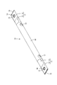
バスバー10は、銅、銅合金、アルミニウム等の金属からなるパイプPにより構成された部材であって、図4に示すように、両端がそれぞれ接続部11となっており、一対の接続部11に挟まれた部分が、冷媒の流路を構成する円筒状の冷媒流通部16となっている。
各接続部11の端部(冷媒流通部16とは反対側の端部)は、対向するパイプの内面同士が密着するように扁平に潰れた平板形状を有する端子部12となっており、端子部12と冷媒流通部16との間の部分は、冷媒流通部16から端子部12に向かって徐々に潰れるように変形する変形部13となっている。端子部12においては、パイプPの対向する内面同士が密着して閉じた(開口していない)状態となっている。各接続部11は、中央部分に、一面から他面まで貫通する挿通孔14を有している。接続部11の端面(冷媒流通部16と反対側の端面)と、挿通孔14の内周面とは、それぞれ、コーキング材15によって覆われており、対向する内面同士の隙間から冷媒が外部に漏れ出さないようになっている。
冷媒流通部16は、外周面から内周面まで貫通する一対の貫通孔(流入口17および吐出口18)を有している。流入口17は、冷媒流通部16の一方の端部付近に、吐出口18は他方の端部付近に、それぞれ配置されている。
冷媒流通部16には、図5に示すように、2つのジョイント部材21を介して2本の送液チューブ24が取り付けられている。
2つのジョイント部材21のそれぞれは、ゴムなどの弾性部材により構成され、2つの管路を繋ぐための一般的な部材であって、図5に示すように、流入口17または吐出口18に嵌め付けられるパッキン部22と、このパッキン部22から連なる筒状のジョイント筒部23とを備えている。2つのジョイント部材21のうち一方のジョイント部材21は、パッキン部22が流入口17に嵌め付けられ、ジョイント筒部23が一方の送液チューブ24に接続されている。このジョイント部材21と送液チューブ24とが、冷媒流通部16の内部への冷媒の供給路となる供給部を構成しており、送液チューブ24には、冷媒を送液する送液装置(送液ポンプなど;図示せず)が接続される。また、他方のジョイント部材21は、パッキン部22が吐出口18に嵌め付けられ、ジョイント筒部23が他方の送液チューブ24に接続されている。このジョイント部材21と送液チューブ24とが、冷媒流通部16からの冷媒の排出路となる排出部を構成している。送液チューブ24としては、樹脂などにより形成された一般的なものを使用できる。
外装材25は、図1に示すように、バスバー10のうち流入口17と吐出口18との間の部分を覆う絶縁性の部材であって、例えば、熱収縮チューブを用いることができる。
上記のような冷却機能付き導電部材1の製造方法の一例を以下に示す。
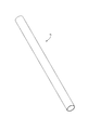
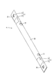
まず、図2に示すような金属製のパイプPの両端を、プレスにより潰し、接続部11を形成する。次に、図3に示すように、プレス後のパイプPに孔開け加工を施し、挿通孔14、流入口17および吐出口18を形成する。次いで、図4に示すように、接続部11の端面と、挿通孔14の内周面とをコーキング材15によりシールする。最後に、冷媒流通部16に外装材25を外装するとともに、ジョイント部材21および送液チューブ24を取り付けて、冷却機能付き導電部材1が完成する。
この冷却機能付き導電部材1を組電池に取り付ける際には、図1に示すように、一の単電池30Aの電極端子31Aに一方の端子部12を重ね、ボルトBを挿通孔14に挿通して電極端子31Aに締め付け固定する。同様に、他の単電池30Bにおいて一の単電池30Aの電極端子31Aとは異なる極性を有する電極端子31Bに他方の端子部12を重ね、ボルトBを挿通孔14に挿通して電極端子31Bに締め付け固定する。同様にして、他の単電池にも順次、冷却機能付き導電部材1を取り付けることによって、複数の単電池を直列に接続することができる。
電池の使用中には、バスバー10に大電流が流れるため、バスバー10が発熱するが、冷媒流通部16内に冷媒を流通させることにより、放熱を促進することができる。このような構成によれば、温度上昇を抑制するために導電部材の断面積を増大させる必要がない。このため、大型化や配電スペースの増大を避けつつ大電流に対応することができる。
以上のように本実施形態によれば、冷却機能付き導電部材1は、バスバー10と、ジョイント部材21と送液チューブ24とを備える。バスバー10は、導電性のパイプPにより構成された部材であって、内部に冷媒を流通可能な冷媒流通部16と、電極端子31A、31Bと接続可能な一対の端子部12とを備える。ジョイント部材21と送液チューブ24とは、冷媒流通部16に接続されて、冷媒流通部16の内部への冷媒の供給路、および、冷媒流通部16からの冷媒の排出路を構成する。一対の端子部12のそれぞれが、パイプPの一部により構成され、対向するパイプPの内面同士が密着するように扁平に潰れた平板形状を有しており、冷媒流通部16が、パイプPにおいて一対の端子部12の間の部分により構成されている。
上記の構成によれば、冷媒流通部16内に冷媒を流通させることにより、バスバー10の放熱を促進することができる。このような構成によれば、温度上昇を抑制するためにバスバーの断面積を増大させる必要がない。このため、大型化や配電スペースの増大を避けつつ大電流に対応することができる。
<変形例>
図6に示すように、冷却機能付き導電部材40は、並列され、連結された複数のバスバー41、51を備えていてもよい。本変形例では、2本のバスバー41、51が並列された例について説明する。なお、本変形例において、実施形態と同様の構成については同一の符号を付して説明を省略する。
図6に示すように、冷却機能付き導電部材40は、並列され、連結された複数のバスバー41、51を備えていてもよい。本変形例では、2本のバスバー41、51が並列された例について説明する。なお、本変形例において、実施形態と同様の構成については同一の符号を付して説明を省略する。
2本のバスバー41、51のうち一方のバスバー(第1バスバー41)は、上記実施形態のバスバー10と同様の構成を備えている。他方のバスバー(第2バスバー51)は、図7に示すように、流入口52A、52Bおよび吐出口53A、53Bを2つずつ備えている点を除き、第1バスバー41と同様の構成を有している。一方の流入口(第1流入口52A)および吐出口(第1吐出口53A)が、冷媒流通部16の一方の端部付近に、互いに対向する位置に配され、他方の流入口(第2流入口52B)および吐出口(第2吐出口53B)が、冷媒流通部16の他方の端部付近に、互いに対向する位置に配されている。
流入口52A、52Bおよび吐出口53A、53Bには、それぞれ、上記実施形態と同様に、ジョイント部材21が嵌め付けられている。
第1流入口52Aおよび第2吐出口53Bに嵌め付けられたジョイント部材21には、それぞれ、上記実施形態と同様に、送液チューブ24が接続され、第1流入口52Aに接続された送液チューブ24には、送液装置が接続される。
第1バスバー41の流入口17に嵌め付けられたジョイント部材21と、第2バスバー51の第1吐出口53Aに嵌め付けられたジョイント部材21との間、および、第1バスバー41の吐出口18に嵌め付けられたジョイント部材21と、第2バスバー51の第2流入口52Bに嵌め付けられたジョイント部材21との間が、それぞれ、連結チューブ54によって接続されている。これにより、第1バスバー41と第2バスバー51とが並列に連結されている。これらの連結チューブ54とジョイント部材21とが、第1バスバー41と第2バスバー51との間での冷媒の送液路となる連結部を構成している。連結チューブ54としては、送液チューブ24と同様に、樹脂などにより形成された一般的なものを使用できる。このようにして、2つのバスバー41、51が並列に接続され、バスバー41、51の内部に冷媒を流通させることができる。
この冷却機能付き導電部材40を組電池に取り付ける際には、図6に示すように、第1の単電池61の一方の電極端子62Aに、第1バスバー41の一方の端子部12を重ね、ボルトBを挿通孔14に挿通して電極端子62Aに締め付け固定する。また、他方の電極端子62Bに、第2バスバー51の一方の端子部12を重ね、ボルトBを挿通孔14に挿通して電極端子62Bに締め付け固定する。そして、同様に、第2の単電池(図示せず)において第1の単電池61の一方の電極端子62Aとは極性が異なる電極端子に、第1バスバー41の他方の端子部12を重ね、ボルトによって固定する。さらに、第3の単電池(図示せず)において第1の単電池の他方の電極端子62Bとは極性が異なる電極端子に、第2バスバー51の他方の端子部12を重ね、ボルトによって固定する。このようにして、複数の単電池が直列に接続される。
本変形例においても、実施形態と同様に、冷媒流通部16内に冷媒を流通させることにより、バスバー41、51からの放熱を促進することができ、実施形態と同様の作用効果が奏される。加えて、複数のバスバー41、51を同時に、効率的に冷却することができる。
なお、本変形例のように複数のバスバー41、51を接続して使用する場合、隣り合うバスバー41、51間の絶縁のため、絶縁性の冷媒を使用することを要する。また、隣り合うバスバー41、51同士を接続する連結チューブ54およびジョイント部材21のうち少なくとも一方が絶縁性であることを要する。
<他の実施形態>
本明細書によって開示される技術は上記記述及び図面によって説明した実施形態に限定されるものではなく、例えば次のような種々の態様も含まれる。
(1)上記実施形態では、冷却機能付き導電部材1を、組電池を構成する単電池同士の接続のために用いる例を示したが、冷却機能付き導電部材の用途は上記実施形態に限らず、例えば、バッテリと、バッテリからの電力を複数の機器に分配するためのジャンクションボックスとの接続、ジャンクションボックスと機器との接続、ジャンクションボックス内に設けられるリレーとサービスプラグとの接続、バッテリとDC/DCコンバータとの接続、バッテリとインバータとの接続、インバータとモータとの接続、モータと機器との接続などを挙げることができる。
本明細書によって開示される技術は上記記述及び図面によって説明した実施形態に限定されるものではなく、例えば次のような種々の態様も含まれる。
(1)上記実施形態では、冷却機能付き導電部材1を、組電池を構成する単電池同士の接続のために用いる例を示したが、冷却機能付き導電部材の用途は上記実施形態に限らず、例えば、バッテリと、バッテリからの電力を複数の機器に分配するためのジャンクションボックスとの接続、ジャンクションボックスと機器との接続、ジャンクションボックス内に設けられるリレーとサービスプラグとの接続、バッテリとDC/DCコンバータとの接続、バッテリとインバータとの接続、インバータとモータとの接続、モータと機器との接続などを挙げることができる。
(2)上記実施形態では、接続部11の端面(冷媒流通部16と反対側の端面)と、挿通孔14の内周面とが、それぞれ、コーキング材15によって覆われていたが、冷媒がバスバーの外部に漏れ出さないようにするための構成は、上記実施形態に限らず、例えば、接続部の端面と、端子挿通孔の内周面とにレーザ溶接を施す方法、金属パイプにおいて接続部となる部分の内側にゴム等の接着剤を塗布しておいてからプレスする方法、接続部をはんだ液に浸漬する方法等を採用することができる。
(3)上記変形例では、2本のバスバー41、51を並列に接続する例を示したが、3本のバスバーを並列して接続してもよい。3本のバスバーが並列された構成は、特に、三相交流用の配線に好適に使用できる。さらに、4本以上のバスバーを並列して接続しても構わない。また、複数のバスバーを直列に接続しても構わない。
1、40…冷却機能付き導電部材
10…バスバー(導電部材)
12…端子部
16…冷媒流通部
21…ジョイント部材(供給部、排出部、連結部)
24…送液チューブ(供給部、排出部)
41…第1バスバー(一の導電部材)
51…第2バスバー(他の導電部材)
54…連結チューブ(連結部)
P…パイプ
10…バスバー(導電部材)
12…端子部
16…冷媒流通部
21…ジョイント部材(供給部、排出部、連結部)
24…送液チューブ(供給部、排出部)
41…第1バスバー(一の導電部材)
51…第2バスバー(他の導電部材)
54…連結チューブ(連結部)
P…パイプ
Claims (2)
- 導電性のパイプにより構成された部材であって、内部に冷媒を流通可能な冷媒流通部と、外部端子と接続可能な一対の端子部とを備える導電部材と、
前記冷媒流通部に接続されて前記冷媒流通部の内部への冷媒の供給路を構成する供給部と、
前記冷媒流通部に接続されて前記冷媒流通部からの冷媒の排出路を構成する排出部とを備え、
前記一対の端子部のそれぞれが、前記パイプの一部により構成され、対向する前記パイプの内面同士が密着するように扁平に潰れた平板形状を有しており、
前記冷媒流通部が、前記パイプにおいて前記一対の端子部間の部分により構成されている、冷却機能付き導電部材。 - 複数の前記導電部材と、
前記複数の導電部材のうち一の導電部材と他の導電部材とを接続して前記一の導電部材と前記他の導電部材との間での前記冷媒の送液路を構成する連結部とを備える、請求項1に記載の冷却機能付き導電部材。
Applications Claiming Priority (2)
| Application Number | Priority Date | Filing Date | Title |
|---|---|---|---|
| JP2016-147278 | 2016-07-27 | ||
| JP2016147278A JP2018018661A (ja) | 2016-07-27 | 2016-07-27 | 冷却機能付き導電部材 |
Publications (1)
| Publication Number | Publication Date |
|---|---|
| WO2018021084A1 true WO2018021084A1 (ja) | 2018-02-01 |
Family
ID=61016785
Family Applications (1)
| Application Number | Title | Priority Date | Filing Date |
|---|---|---|---|
| PCT/JP2017/025874 Ceased WO2018021084A1 (ja) | 2016-07-27 | 2017-07-18 | 冷却機能付き導電部材 |
Country Status (2)
| Country | Link |
|---|---|
| JP (1) | JP2018018661A (ja) |
| WO (1) | WO2018021084A1 (ja) |
Cited By (7)
| Publication number | Priority date | Publication date | Assignee | Title |
|---|---|---|---|---|
| JP2019204633A (ja) * | 2018-05-22 | 2019-11-28 | 矢崎総業株式会社 | 接続部材 |
| WO2021111984A1 (ja) * | 2019-12-04 | 2021-06-10 | 株式会社オートネットワーク技術研究所 | 回路構成体 |
| WO2021259638A1 (de) * | 2020-06-24 | 2021-12-30 | Witzenmann Gmbh | Batteriezellen-verbindungselement, batteriezellen-verbindungsmodul, batteriezellen-verbindungsanordnung und verfahren zum temperieren und elektrischen kontaktieren von batteriezellen |
| US11411265B2 (en) * | 2017-04-26 | 2022-08-09 | Bayerische Motoren Werke Aktiengesellschaft | Cover for electrically coupling multiple storage cells of an electrical energy storage module |
| US11476654B2 (en) * | 2020-06-17 | 2022-10-18 | Yazaki Corporation | Single to multiple layer integral busbar structure |
| WO2024004727A1 (ja) * | 2022-06-27 | 2024-01-04 | 株式会社オートネットワーク技術研究所 | 回路構成体 |
| JP2025056468A (ja) * | 2023-09-27 | 2025-04-08 | 矢崎総業株式会社 | 冷却構造付き導電部材 |
Families Citing this family (14)
| Publication number | Priority date | Publication date | Assignee | Title |
|---|---|---|---|---|
| JP2021086735A (ja) * | 2019-11-28 | 2021-06-03 | 日本ケミコン株式会社 | 蓄電モジュールおよびその製造方法 |
| JP7474618B2 (ja) * | 2020-03-24 | 2024-04-25 | 日本特殊陶業株式会社 | バスバーおよび組電池 |
| JP7380384B2 (ja) * | 2020-03-30 | 2023-11-15 | 株式会社アイシン | 車両用駆動装置、中空バスバー、中空バスバー形成方法 |
| KR20220049724A (ko) * | 2020-10-15 | 2022-04-22 | 주식회사 엘지에너지솔루션 | 냉각성능이 향상된 전지 팩 및 이를 포함하는 디바이스 |
| DE102021111741A1 (de) * | 2021-05-06 | 2022-12-15 | Dr. Ing. H.C. F. Porsche Aktiengesellschaft | Funktionsintegrierter Separator, eine diesen aufweisende Batteriezelle sowie Verfahren zum Bereitstellen derselben |
| US20230113884A1 (en) * | 2021-10-12 | 2023-04-13 | Lg Energy Solution, Ltd. | Battery pack and vehicle including the same |
| US12463283B2 (en) | 2021-10-12 | 2025-11-04 | Lg Energy Solution, Ltd. | Battery pack and vehicle including the same |
| KR20240015312A (ko) | 2022-07-27 | 2024-02-05 | 주식회사 엘지에너지솔루션 | 냉각 부재를 포함하는 버스바 및 이를 포함하는 전지팩 |
| KR102881209B1 (ko) * | 2022-08-16 | 2025-11-05 | 주식회사 엘지에너지솔루션 | 소화액체가 포함된 인터-모듈 버스바 |
| JP2026034874A (ja) * | 2022-12-28 | 2026-03-04 | 住友ベークライト株式会社 | 温調機能付きコネクターおよび樹脂バッテリーモジュール |
| JP7745983B2 (ja) | 2023-09-20 | 2025-09-30 | 矢崎総業株式会社 | 冷却構造付き導体部材 |
| JP7745984B2 (ja) | 2023-09-20 | 2025-09-30 | 矢崎総業株式会社 | 冷却構造付き導体部材 |
| JP7717431B2 (ja) | 2023-09-20 | 2025-08-04 | 矢崎総業株式会社 | 冷媒流路付き導電部材 |
| KR20250153553A (ko) * | 2024-04-18 | 2025-10-27 | 삼성에스디아이 주식회사 | 이차 전지 |
Citations (3)
| Publication number | Priority date | Publication date | Assignee | Title |
|---|---|---|---|---|
| JPS5521546U (ja) * | 1978-07-28 | 1980-02-12 | ||
| JP2004095530A (ja) * | 2002-06-20 | 2004-03-25 | Furukawa Electric Co Ltd:The | パイプブスバー、その絶縁被覆方法及び絶縁被覆構造 |
| JP2014195392A (ja) * | 2013-02-27 | 2014-10-09 | Jtekt Corp | モータ駆動用制御装置 |
-
2016
- 2016-07-27 JP JP2016147278A patent/JP2018018661A/ja active Pending
-
2017
- 2017-07-18 WO PCT/JP2017/025874 patent/WO2018021084A1/ja not_active Ceased
Patent Citations (3)
| Publication number | Priority date | Publication date | Assignee | Title |
|---|---|---|---|---|
| JPS5521546U (ja) * | 1978-07-28 | 1980-02-12 | ||
| JP2004095530A (ja) * | 2002-06-20 | 2004-03-25 | Furukawa Electric Co Ltd:The | パイプブスバー、その絶縁被覆方法及び絶縁被覆構造 |
| JP2014195392A (ja) * | 2013-02-27 | 2014-10-09 | Jtekt Corp | モータ駆動用制御装置 |
Cited By (12)
| Publication number | Priority date | Publication date | Assignee | Title |
|---|---|---|---|---|
| US11411265B2 (en) * | 2017-04-26 | 2022-08-09 | Bayerische Motoren Werke Aktiengesellschaft | Cover for electrically coupling multiple storage cells of an electrical energy storage module |
| JP2019204633A (ja) * | 2018-05-22 | 2019-11-28 | 矢崎総業株式会社 | 接続部材 |
| WO2021111984A1 (ja) * | 2019-12-04 | 2021-06-10 | 株式会社オートネットワーク技術研究所 | 回路構成体 |
| CN114762204A (zh) * | 2019-12-04 | 2022-07-15 | 株式会社自动网络技术研究所 | 电路结构体 |
| CN114762204B (zh) * | 2019-12-04 | 2024-05-03 | 株式会社自动网络技术研究所 | 电路结构体 |
| US11476654B2 (en) * | 2020-06-17 | 2022-10-18 | Yazaki Corporation | Single to multiple layer integral busbar structure |
| WO2021259638A1 (de) * | 2020-06-24 | 2021-12-30 | Witzenmann Gmbh | Batteriezellen-verbindungselement, batteriezellen-verbindungsmodul, batteriezellen-verbindungsanordnung und verfahren zum temperieren und elektrischen kontaktieren von batteriezellen |
| DE102020116654A1 (de) | 2020-06-24 | 2021-12-30 | Witzenmann Gmbh | Batteriezellen-Verbindungselement, Batteriezellen-Verbindungsmodul, Batteriezellen-Verbindungsanordnung und Verfahren zum Temperieren und elektrischen Kontaktieren von Batteriezellen |
| WO2024004727A1 (ja) * | 2022-06-27 | 2024-01-04 | 株式会社オートネットワーク技術研究所 | 回路構成体 |
| JP2024003646A (ja) * | 2022-06-27 | 2024-01-15 | 株式会社オートネットワーク技術研究所 | 回路構成体 |
| JP7721066B2 (ja) | 2022-06-27 | 2025-08-12 | 株式会社オートネットワーク技術研究所 | 回路構成体 |
| JP2025056468A (ja) * | 2023-09-27 | 2025-04-08 | 矢崎総業株式会社 | 冷却構造付き導電部材 |
Also Published As
| Publication number | Publication date |
|---|---|
| JP2018018661A (ja) | 2018-02-01 |
Similar Documents
| Publication | Publication Date | Title |
|---|---|---|
| WO2018021084A1 (ja) | 冷却機能付き導電部材 | |
| US11641098B1 (en) | Cooling system for busbars | |
| US8568918B2 (en) | Battery having a plurality of single cells | |
| KR102403695B1 (ko) | 이차 전지 및 그 모듈 | |
| KR100987299B1 (ko) | 고무 냉각 매니폴드를 포함하는 전지모듈 | |
| US9936616B2 (en) | Electric power convertor | |
| CN102379058B (zh) | 电压感测部件和采用该电压感测部件的电池模块 | |
| US10449871B1 (en) | Electrical power terminal for a charging system | |
| US9882187B2 (en) | Battery cell, battery, or battery cell module, method for producing a battery cell, and motor vehicle | |
| US8470467B2 (en) | Battery connection topology | |
| JP5825264B2 (ja) | 電池システム | |
| CN110140233A (zh) | 电池系统及包括其的车辆 | |
| CN106803608A (zh) | 电池模组和新能源汽车 | |
| JP2016514345A (ja) | バッテリーハウジング | |
| US10608301B2 (en) | Power electronics with integrated busbar cooling | |
| KR101711979B1 (ko) | 이차 전지 및 그 모듈 | |
| WO2016091133A1 (zh) | 电发热部件的热管理装置 | |
| CN112117412A (zh) | 一种电动汽车动力电池组 | |
| KR20150100471A (ko) | 전지모듈 | |
| US20190305466A1 (en) | Connecting Element and Connecting Apparatus for Electrically Connecting a Cable to an Electrical Device of a Motor Vehicle | |
| KR20220166267A (ko) | 상호연결된 배터리 모듈 시스템, 조립체 및 방법 | |
| US12586841B2 (en) | Battery module coolant channels | |
| KR102721243B1 (ko) | 셀별 방열 구조가 적용된 소형 전기차용 배터리 팩 | |
| WO2025001163A1 (zh) | 储能装置 | |
| US12142742B2 (en) | Method of cooling battery cells |
Legal Events
| Date | Code | Title | Description |
|---|---|---|---|
| 121 | Ep: the epo has been informed by wipo that ep was designated in this application |
Ref document number: 17834092 Country of ref document: EP Kind code of ref document: A1 |
|
| NENP | Non-entry into the national phase |
Ref country code: DE |
|
| 122 | Ep: pct application non-entry in european phase |
Ref document number: 17834092 Country of ref document: EP Kind code of ref document: A1 |