WO2018020958A1 - 台棒 - Google Patents
台棒 Download PDFInfo
- Publication number
- WO2018020958A1 WO2018020958A1 PCT/JP2017/024210 JP2017024210W WO2018020958A1 WO 2018020958 A1 WO2018020958 A1 WO 2018020958A1 JP 2017024210 W JP2017024210 W JP 2017024210W WO 2018020958 A1 WO2018020958 A1 WO 2018020958A1
- Authority
- WO
- WIPO (PCT)
- Prior art keywords
- base
- unit
- main
- tip
- intermediate unit
- Prior art date
- Legal status (The legal status is an assumption and is not a legal conclusion. Google has not performed a legal analysis and makes no representation as to the accuracy of the status listed.)
- Ceased
Links
Images














Classifications
-
- B—PERFORMING OPERATIONS; TRANSPORTING
- B66—HOISTING; LIFTING; HAULING
- B66C—CRANES; LOAD-ENGAGING ELEMENTS OR DEVICES FOR CRANES, CAPSTANS, WINCHES, OR TACKLES
- B66C23/00—Cranes comprising essentially a beam, boom, or triangular structure acting as a cantilever and mounted for translatory of swinging movements in vertical or horizontal planes or a combination of such movements, e.g. jib-cranes, derricks, tower cranes
- B66C23/18—Cranes comprising essentially a beam, boom, or triangular structure acting as a cantilever and mounted for translatory of swinging movements in vertical or horizontal planes or a combination of such movements, e.g. jib-cranes, derricks, tower cranes specially adapted for use in particular purposes
- B66C23/26—Cranes comprising essentially a beam, boom, or triangular structure acting as a cantilever and mounted for translatory of swinging movements in vertical or horizontal planes or a combination of such movements, e.g. jib-cranes, derricks, tower cranes specially adapted for use in particular purposes for use on building sites; constructed, e.g. with separable parts, to facilitate rapid assembly or dismantling, for operation at successively higher levels, for transport by road or rail
- B66C23/28—Cranes comprising essentially a beam, boom, or triangular structure acting as a cantilever and mounted for translatory of swinging movements in vertical or horizontal planes or a combination of such movements, e.g. jib-cranes, derricks, tower cranes specially adapted for use in particular purposes for use on building sites; constructed, e.g. with separable parts, to facilitate rapid assembly or dismantling, for operation at successively higher levels, for transport by road or rail constructed to operate at successively higher levels
Definitions
- the present invention relates to a pole used for assembling and dismantling a steel tower.
- Patent Document 1 describes an example of a base bar. As described in Patent Document 1, the pedestal is attached to the main pillar material of the steel tower via an attachment fitting.
- a support wire is attached to the base bar.
- the angle formed by the base bar with respect to the vertical line is adjusted. Thereby, the operator can move the to-be-conveyed member suspended by the base bar to a desired position.
- the pedestal may come into contact with the main pillar material of the steel tower supporting the pedestal. For this reason, there is a limit to increasing the range in which the transported member can move.
- the present invention has been made in view of the above, and an object of the present invention is to provide a pedestal capable of increasing the range in which the transported member can move.
- a base rod includes a base attachment attached to the inside of a main pillar material of a steel tower, and a rotation axis along a horizontal direction passing through the base attachment.
- a base unit having a base body that can be rotated together with the base attachment, a tip unit to which a support wire is attached, and a plurality of intermediate units for connecting the base unit and the tip unit.
- the main pillar material is inclined such that the upper end portion is located inside the tower from the lower end portion, and the rotation axis passes through the center of gravity of the base body and is a center line along the longitudinal direction of the base body
- the intermediate unit that is located on the main column material side and is adjacent to the base unit, it is perpendicular to both the rotating shaft and the center line. Width such is smaller toward the base unit side.
- the pedestal makes it difficult for the pedestal to come into contact with the main column material even if the angle formed by the pedestal with respect to the horizontal plane increases.
- the angle that the pedestal makes with the horizontal plane is the upper limit angle in the prior art (the angle at which the pedestal contacts the main column material)
- the distance from the center line to the rotation axis is not more than half of the minimum width of the base body in the direction orthogonal to both the rotation axis and the center line.
- the base body includes four main members, and the four main members are respectively arranged at the apexes of a square when viewed from the longitudinal direction of the base body.
- FIG. 1 is a mimetic diagram showing the pedestal concerning this embodiment attached to the steel tower.
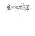
- FIG. 2 is a front view showing a pedestal according to the present embodiment.
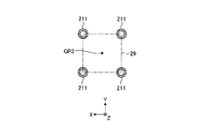
- FIG. 3 is a front view showing the base unit according to the present embodiment.
- 4 is a cross-sectional view taken along the line DD in FIG.
- FIG. 5 is a front view showing the tip unit according to the present embodiment.
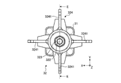
- FIG. 6 is a left side view showing the tip unit according to the present embodiment.
- 7 is a cross-sectional view taken along line EE in FIG.
- FIG. 10 is an enlarged view of a portion B in FIG. FIG.
- FIG. 11 is a perspective view of a portion B in FIG. 12 is a plan view of a portion B in FIG.
- FIG. 13 is an enlarged view of a portion C in FIG.
- FIG. 14 is a front view showing the mounting bracket according to the present embodiment.
- FIG. 15 is a plan view showing a mounting bracket according to the present embodiment.
- FIG. 16 is a right side view showing the mounting bracket according to the present embodiment.
- FIG. 17 is an enlarged view showing a lower end portion of the bar according to the first comparative example attached to the steel tower.
- 18 is a cross-sectional view taken along the line GG in FIG.
- FIG. 19 is an enlarged view showing a lower end portion of the bar according to the present embodiment attached to the steel tower.
- FIG. 20 is a cross-sectional view taken along the line II in FIG.
- FIG. 21 is an enlarged view showing a part of the bar according to the second comparative example attached to the steel tower.
- 22 is a cross-sectional view taken along line JJ in FIG.
- FIG. 23 is an enlarged view showing a part of a pedestal according to the present embodiment attached to a steel tower.
- 24 is a cross-sectional view taken along the line KK in FIG.
- FIG. 25 is a flowchart showing a method of assembling the base bar according to the present embodiment.
- FIG. 26 is a diagram illustrating a support bar according to the present embodiment in the middle of assembly.
- FIG. 27 is a view showing a support bar according to the present embodiment in the middle of assembly.
- FIG. 28 is a diagram showing the base bar according to the present embodiment in the middle of assembly.
- FIG. 29 is a view showing a support bar according to the present embodiment in the middle of assembly.
- FIG. 30 is a view showing a support bar according to the present embodiment in the middle of assembly.
- FIG. 31 is a front view showing a base unit according to a modification.
- FIG. 1 is a mimetic diagram showing the pedestal concerning this embodiment attached to the steel tower.
- the pole 1 is used when the steel tower 10 is assembled or when the steel tower 10 is disassembled. That is, the pedestal 1 is used for the steel tower 10 under construction or the steel tower 10 to be dismantled.
- the pedestal 1 is attached to the main pillar material 101 of the steel tower 10.
- the steel tower 10 has, for example, four main pillar materials 101.
- the main column 101 is angle steel. That is, the vertical cross section with respect to the longitudinal direction of the main pillar 101 is L-shaped.
- the four main pillar members 101 are arranged at positions corresponding to the vertices of the square in plan view.
- the longitudinal direction of the main column 101 is inclined with respect to the vertical line. Specifically, the main pillar material 101 is inclined so that the upper end portion is located inside the steel tower 10 from the lower end portion.
- the bar 1 is supported by the mounting bracket 5 and the support wire 72 shown in FIG.
- the pedestal 1 is attached to the main pillar material 101 via the mounting bracket 5.
- the mounting bracket 5 supports the pedestal 1 so that the pedestal 1 can rotate around the rotation axis Ax along the horizontal direction.
- One end of the support wire 72 is connected to the tip of the base bar 1, and the other end of the support wire 72 is connected to, for example, a winch installed on the ground.
- the support wire 72 is wound or unwound by the winch. Thereby, the angle which the base bar 1 makes with respect to a horizontal surface changes.
- a lifting wire 71 is attached to the base bar 1.
- the lifting wire 71 is a wire for lifting the constituent material 102 of the tower 10.
- the lifting wire 71 is attached to the pulley 81, the pulley 82, and the pulley 83.
- the pulley 81 is fixed to the mounting bracket 5, for example.
- the pulley 82 is fixed to the tip attachment 32 provided at the tip of the base rod 1, for example.
- the pulley 83 is suspended from the pulley 82 and connected to the component 102.
- the lifting wire 71 is connected to, for example, a winch installed on the ground.
- the lifting wire 71 is wound up or drawn out by the winch. Thereby, the constituent material 102 is conveyed in the up-down direction.
- FIG. 2 is a front view showing a pedestal according to this embodiment.
- the base bar 1 includes a base unit 2, a tip unit 3, and an intermediate unit 4.
- the base bar 1 includes ten intermediate units 4 and four intermediate unit pairs 40.
- the intermediate unit pair 40 is a pair of two intermediate units 4 assembled with bolts.
- an XYZ orthogonal coordinate system is used.
- the X axis is an axis along the rotation axis Ax when the pedestal 1 is attached to the steel tower 10.
- the Z axis is an axis along the longitudinal direction of the base bar 1.
- the Y axis is an axis orthogonal to the X axis and the Z axis.
- the direction from the base unit 2 toward the tip unit 3 is described as a + Z direction, and the direction opposite to the + Z direction is described as a ⁇ Z direction. That is, the left direction in FIG. 2 is the + Z direction, and the right direction in FIG. 2 is the ⁇ Z direction.
- the base unit 2, the intermediate unit 4, the four intermediate unit pairs 40 (eight intermediate units 4), the intermediate unit 4, and the tip unit 3 are arranged in this order from one end of the base 1.
- the base unit 2 is joined to the intermediate unit 4 with bolts.
- the intermediate unit 4 joined to the base unit 2 with a bolt is joined to the intermediate unit pair 40 with a pin.
- the intermediate unit pairs 40 are joined by pins.
- the tip unit 3 is joined to the intermediate unit 4 with a bolt.
- the intermediate unit 4 joined to the tip unit 3 with a bolt is joined to the intermediate unit pair 40 with a pin.
- first joint J1 that joins the base unit 2 and the intermediate unit 4 is the bolt joint 9.
- the second joint J2 that joins the tip unit 3 and the intermediate unit 4 is a bolt joint 9.
- the third joint J3 that joins the adjacent intermediate units 4 is the bolt joint 9 or the pin joint 6.
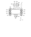
- FIG. 3 is a front view showing the base unit according to the present embodiment. 4 is a cross-sectional view taken along the line DD in FIG.
- the base unit 2 is located at the lower end when the base 1 is attached to the steel tower 10 as shown in FIG.
- the length of the base unit 2 in the Z direction is, for example, 1.5 m.
- the base unit 2 includes a base body 21 and a base attachment 22.
- the base body 21 includes four main members 211 and a plurality of diagonal members 212 that connect the main members 211 to each other.
- the main material 211 and the diagonal material 212 are cylindrical members made of, for example, steel.
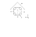
- the four main members 211 are arranged at the apexes of the square 29 when viewed from the Z direction.
- the main material 211 is inclined with respect to the Z axis. Specifically, when viewed from the X direction, the width D3 in the Y direction at the end portion in the ⁇ Z direction of the base body 21 is smaller than the width D2 in the Y direction at the end portion in the + Z direction of the base body 21.
- the base attachment 22 is attached to one end of the base body 21.
- the base attachment 22 is a plate-like member having an attachment hole 23 along the X axis.
- the base attachment 22 is attached to the inside of the main pillar member 101 via the attachment fitting 5.
- a connecting member 545 described later is inserted into the attachment hole 23.
- the pedestal 1 attached to the main pillar 101 rotates about a rotation axis Ax along the axial direction of the connecting member 545.
- the mounting hole 23 passes through the center of gravity GP2 of the base body 21 and is separated in the Y direction with respect to the center line L1 along the Z axis. That is, the rotation axis Ax is eccentric with respect to the center line L1.
- the distance D1 from the center line L1 to the mounting hole 23 is smaller than half of the width D2, for example. It can be said that the center line L1 is a bisector of a line segment connecting one end of one main member 211 and one end of another main member 211. Further, it can be said that the center line L1 is a straight line having the same distance from the two main members 211 when viewed from the X-axis direction. As shown in FIG. 3, when viewed from the X direction, the main material 211 makes an angle ⁇ with respect to the center line L1.
- the weight of the pedestal 1 acts on the base attachment 22. At this time, it is desirable that the bending moment generated in the base attachment 22 is as small as possible.
- the distance D1 is smaller than half of the width D2
- the bending moment generated in the base attachment 22 when the base bar 1 is attached to the steel tower 10 is suppressed. For this reason, damage to the base attachment 22 is prevented.
- the distance D1 is preferably smaller than half of the width D3. Thereby, damage to base attachment 22 is prevented more.
- FIG. 5 is a front view showing the tip unit according to the present embodiment.
- FIG. 6 is a left side view showing the tip unit according to the present embodiment.
- 7 is a cross-sectional view taken along line EE in FIG.
- the tip unit 3 is located at the upper end when the base 1 is attached to the steel tower 10 as shown in FIG.
- the length of the tip unit 3 in the Z direction is, for example, 1.5 m.
- the tip unit 3 includes a tip body 31 and a tip attachment 32.
- the front end body 31 includes four main members 311 and a plurality of diagonal members 312 that connect the main members 311 to each other.
- the main material 311 and the diagonal material 312 are cylindrical members made of steel, for example.
- the four main members 311 are arranged at the vertices of a square when viewed from the Z direction, similarly to the base body 21. As shown in FIG. 5, the main material 311 is inclined with respect to the Z axis.
- the width D5 in the Y direction at the end in the + Z direction of the front end body 31 is smaller than the width D4 in the Y direction at the end in the ⁇ Z direction of the front end body 31.
- the width D4 is the same as the width D2 (see FIG.
- the width D5 is the same as the width D3 (see FIG. 3).
- the main material 311 when viewed from the X direction, forms an angle ⁇ with respect to the center line L1.
- the size of the angle ⁇ is equal to the size of the angle ⁇ shown in FIG.
- the tip attachment 32 is attached to one end of the tip body 31. As shown in FIGS. 6 and 7, the tip attachment 32 includes a fixed portion 321, a shaft 322, a nut 323, a sleeve 325, a bearing 326, and a rotating portion 324.
- the fixing portion 321 is fixed to the end portion of the distal end body 31.
- the support wire 72 shown in FIG. 1 is attached to the fixing portion 321 through a hole provided in the fixing portion 321.
- the shaft 322 is a bolt fixed to the flange 329.
- the flange 329 is fixed to the end of the distal end body 31.
- the nut 323 is a member for positioning the rotating part 324.
- the sleeve 325 is a cylindrical member fitted to the shaft 322.
- the bearing 326 is fitted on the outer peripheral surface of the sleeve 325.
- the rotating part 324 is fitted on the outer ring of the bearing 326 and rotates around the shaft 322.
- the rotating unit 324 includes, for example, four wings 3241.
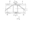
- a support wire 72 or a pulley 82 shown in FIG. 1 is attached to the wing 3241 through a hole provided in the wing 3241.
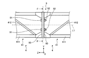
- FIG. 8 is an enlarged view of part A in FIG. 9 is a cross-sectional view taken along line FF in FIG.
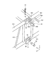
- FIG. 10 is an enlarged view of a portion B in FIG.
- FIG. 11 is a perspective view of a portion B in FIG. 12 is a plan view of a portion B in FIG.
- the intermediate unit 4 is a member for connecting the base unit 2 and the tip unit 3.
- FIG. 13 is an enlarged view of a portion C in FIG.
- the length of the intermediate unit 4 in the Z direction is, for example, 1.5 m.
- the intermediate unit 4 includes an intermediate body 41.
- the intermediate body 41 includes four main members 411 and a plurality of diagonal members 412 that connect the main members 411 to each other.
- the main material 411 and the diagonal material 412 are cylindrical members made of, for example, steel.
- the four main members 411 are arranged at the vertices of a square when viewed from the Z direction, similarly to the base body 21.
- the four main members 411 are parallel to each other.
- the center of gravity GP4 of the intermediate body 41 shown in FIG. 9 is collinear with the center of gravity GP2 of the base body 21 (see FIG. 3) and the center of gravity GP3 of the tip body 31 (see FIG. 5).
- diagonal members 412 adjacent in the Z direction are arranged in opposite directions. That is, the plurality of diagonal members 412 are arranged in a zigzag manner. Thereby, the torsional strength of the base bar 1 is improved.
- the bolt joint 9 includes a flange 93, a bolt 91, and a nut 92.
- the flange 93 is fixed to one end of the intermediate body 41.
- the adjacent intermediate units 4 are arranged so that the flanges 93 face each other.
- Adjacent intermediate units 4 are joined by bolts 91 and nuts 92 attached to holes provided in the flange 93.
- bolts 91 and nuts 92 are arranged, for example, at eight locations.
- the nut 92 is preferably tightened with a predetermined torque. Therefore, the nut 92 is tightened in a state where the two intermediate units 4 are placed sideways on the ground or the jig.
- the bolt joint 9 between the base unit 2 and the intermediate unit 4 and the bolt joint 9 between the tip unit 3 and the intermediate unit 4 are the same as the bolt joint 9 between the two intermediate units 4. is there.
- the pin joint 6 is provided at one end of the intermediate body 41.
- the pin joint 6 includes a female member 62, a male member 61, a pin 64, and a lock pin 65.
- the female member 62 is a member having a substantially U shape when viewed from the Y direction.
- the female member 62 includes two holes 62h that overlap when viewed from the X direction.
- the male member 61 fits into the female member 62.
- the male member 61 includes a hole 61h that overlaps the two holes 62h.
- the pin 64 is disposed at a position straddling the hole 62h and the hole 61h.
- the pin 64 includes a base portion 641, a retaining portion 642, a tapered portion 643, and a hole 644.
- the outer periphery of the retaining portion 642 is larger than the outer periphery of the base portion 641.
- the outer periphery of the tapered portion 643 is smaller than the outer periphery of the base portion 641.
- the outer periphery of the taper portion 643 decreases toward the tip. Thereby, the pin 64 is easily inserted into the hole 62h and the hole 61h.
- the lock pin 65 is a so-called snap pin.
- the lock pin 65 is inserted into the hole 644 after the pin 64 passes through the hole 62h and the hole 61h.
- the pin 64 is positioned by the retaining portion 642 and the lock pin 65.
- the two intermediate units 4 are joined by the pins 64.
- the two intermediate units 4 are joined by the pins 64.
- the connection work by the pin 64 can be performed even in a narrow place.
- the main material 411 is inclined with respect to the Z axis.
- the width D7 in the Y direction at the end in the ⁇ Z direction of the intermediate unit 4a is smaller than the width D6 in the Y direction at the end in the + Z direction of the intermediate unit 4a.
- the width D7 is the same as the width D2 (see FIG. 3).
- the main material 411 of the intermediate unit 4a forms an angle ⁇ with respect to the center line L1.
- the size of the angle ⁇ is equal to the size of the angle ⁇ shown in FIG.
- the main material 411 is inclined with respect to the Z axis.
- the width D9 in the Y direction at the end in the ⁇ Z direction of the intermediate unit 4b is smaller than the width D8 in the Y direction at the end in the + Z direction of the intermediate unit 4b.
- the width D9 is the same as the width D6.
- the main material 411 of the intermediate unit 4b forms an angle ⁇ with respect to the center line L1.
- the magnitude of the angle ⁇ is equal to the magnitude of the angle ⁇ .
- the third joint J3 between the intermediate unit 4a and the intermediate unit 4b is a pin joint 6.
- the male member 61 and the female member 62 of the pin joint 6 located between the intermediate unit 4a and the intermediate unit 4b are not inclined with respect to the Z axis. That is, as shown in FIG. 13, the straight line L2 forms an angle with the main material 411 and is parallel to the center line L1.
- the straight line L2 is a straight line parallel to the outer edges of the male member 61 and the female member 62 when viewed from the X direction. If the straight line L2 is inclined with respect to the center line L1, the positions of the holes 61h and the holes 62h are likely to be shifted between the pin joints 6 adjacent in the X direction.
- the straight line L2 is parallel to the center line L1
- alignment of the hole 61h and the hole 62h between the pin joints 6 adjacent to each other in the X direction becomes easy.
- the female member 62 is attached to the intermediate unit 4a in one of the two pin joints 6 arranged in the Y direction
- the male member 61 is attached to the intermediate unit 4b on the other side. That is, in the two pin joints 6 arranged in the Y direction, the arrangement of the male member 61 and the female member 62 is reversed.
- an intermediate unit 4a is attached to the tip unit 3
- an intermediate unit 4b is attached to the intermediate unit 4a.
- the intermediate unit 4 a and the intermediate unit 4 b arranged on the tip unit 3 side are also joined by the pin joint 6.
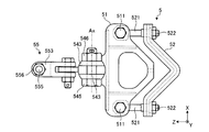
- FIG. 14 is a front view showing the mounting bracket according to the present embodiment.
- FIG. 15 is a plan view showing a mounting bracket according to the present embodiment.
- FIG. 16 is a right side view showing the mounting bracket according to the present embodiment.
- the mounting bracket 5 is a device arranged between the base bar 1 and the main pillar 101 of the steel tower 10.
- the mounting bracket 5 supports the pedestal 1 so that the pedestal 1 can rotate around a rotation axis Ax parallel to the horizontal plane.
- the mounting bracket 5 includes an inner plate 51, an outer plate 52, a base bar connecting portion 54, and a pulley connecting portion 55.
- the inner plate 51 is arranged inside the main pillar 101 made of angle steel.
- the outer plate 52 is disposed outside the main pillar material 101.
- Bolts 511 are attached to the inner plate 51 with nuts 512.
- An eyebolt 521 is attached to the outer plate 52 with a nut 522.
- the bolt 511 passes through the ring of the eyebolt 521.
- the nut 522 is tightened, the main pillar material 101 is sandwiched between the inner plate 51 and the outer plate 52. Thereby, the mounting bracket 5 is fixed to the main pillar material 101.
- the pedestal coupling portion 54 is a member that supports the pedestal 1. As shown in FIGS. 14 to 16, the base bar connecting portion 54 includes a bolt 541, a nut 542, a pair of hold plates 543, a connecting member 545, and a nut 546.
- the bolt 541 passes through the inner plate 51 and is fixed to the inner plate 51 with a nut 542.
- the pair of hold plates 543 are plate-like members that are parallel to each other. The pair of hold plates 543 protrude from the ends of the bolts 541.
- the base attachment 22 (see FIG. 3) of the base unit 2 is disposed between a pair of hold plates 543.
- the connecting member 545 passes through the holding plate 543 and the attachment hole 23 of the base attachment 22, and is fixed to the hold plate 543 with a nut 546. Thereby, the base bar 1 is connected to the base bar connecting portion 54.
- the pedestal 1 can rotate around a rotation axis Ax along the axial direction of the connecting member 545.
- the pulley connecting portion 55 is a member that supports the pulley 81 (see FIG. 1). As shown in FIGS. 14 and 15, the pulley coupling portion 55 includes a pair of hold plates 553, bolts 555, and nuts 556.
- the pair of hold plates 553 are plate-like members that are parallel to each other.
- the pair of hold plates 553 are fixed to the inner plate 51.
- the support fitting provided on the pulley 81 is disposed between the pair of hold plates 553.
- the bolt 555 passes through the hold plate 553 and the support fitting of the pulley 81 and is fixed to the hold plate 553 with a nut 556. As a result, the pulley 81 is connected to the pulley connecting portion 55.
- FIG. 17 is an enlarged view showing the lower end portion of the bar according to the first comparative example attached to the steel tower.
- 18 is a cross-sectional view taken along the line GG in FIG.
- FIG. 19 is an enlarged view showing a lower end portion of the bar according to the present embodiment attached to the steel tower.
- 20 is a cross-sectional view taken along the line II in FIG.
- the base unit 2Z according to the first comparative example includes a base attachment 22Z different from the base attachment 22 according to the present embodiment.
- the attachment hole 23Z provided in the base attachment 22Z is on the center line L1 when viewed in the X direction.
- the base unit 2Z according to the first comparative example and the base unit 2 according to the present embodiment are attached to the main column member 101 via the same mounting bracket 5. For this reason, the distance G1Z from the mounting hole 23Z to the corner portion 101a of the main column member 101 is the same as the distance G1 from the mounting hole 23 to the corner portion 101a of the main column member 101.
- the angle ⁇ Z formed by the center line L ⁇ b> 1 and the horizontal line H increases, the base unit 2 ⁇ / b> Z contacts the main pillar material 101.
- the angle ⁇ Z when the base unit 2Z is in contact with the main column member 101 is Z °
- the upper limit of the angle ⁇ Z is Z °.
- the mounting hole 23 is separated in the Y direction with respect to the center line L1. Therefore, even if the angle ⁇ 1 (see FIG. 19) formed by the center line L1 shown with respect to the horizontal line H reaches Z ° of the first comparative example, the base unit 2 does not contact the main column member 101. That is, as shown in FIG. 20, a gap is generated between the base unit 2 and the main pillar material 101. For this reason, the upper limit of the angle ⁇ 1 is larger than the upper limit (Z °) of the angle ⁇ Z. According to the pedestal 1 according to the present embodiment, the movable range of the tip unit 3 is increased as compared with the first comparative example.
- FIG. 21 is an enlarged view showing a part of the base bar according to the second comparative example attached to the steel tower.
- 22 is a cross-sectional view taken along line JJ in FIG.
- FIG. 23 is an enlarged view showing a part of a pedestal according to the present embodiment attached to a steel tower.
- 24 is a cross-sectional view taken along the line KK in FIG.
- the base bar 1Y according to the second comparative example is different from the present embodiment in that the main material 411 is parallel to the center line L1 in all the intermediate units 4. That is, the base bar 1Y does not include the intermediate unit 4 (the intermediate unit 4a and the intermediate unit 4b shown in FIG. 13) in which the main material 411 is inclined with respect to the center line L1.
- the bar 1Y has a base unit 2 similar to the present embodiment.
- the pulley 82 and the lifting wire 71 are in contact with the lower end portion of the tip unit 3 (the boundary portion between the tip unit 3 and the intermediate unit 4).
- the angle ⁇ Y at this time is X °.
- the intermediate unit 4a and the intermediate unit 4b shown in FIG. For this reason, even if the angle ⁇ 2 (see FIG. 23) formed by the center line L1 with respect to the horizontal line H reaches Y ° in the second comparative example, the base bar 1 does not contact the main pillar material 101. That is, as shown in FIG. 24, a gap is generated between the base bar 1 and the main pillar material 101. For this reason, the upper limit of the angle ⁇ 2 is larger than the upper limit (Y °) of the angle ⁇ Y. According to the pedestal 1 according to the present embodiment, the movable range of the tip unit 3 is increased as compared with the second comparative example.
- the intermediate unit 4a and the intermediate unit 4b shown in FIG. For this reason, even if the angle ⁇ 2 reaches X ° in the second comparative example, the pulley 82 and the lifting wire 71 do not contact the lower end portion of the tip unit 3. According to the pedestal 1 according to the present embodiment, the pulley 82 and the lifting wire 71 are less likely to contact the tip unit 3 as compared to the second comparative example.
- FIG. 25 is a flowchart showing a method of assembling the support bar according to the present embodiment.
- FIG. 26 is a diagram illustrating a support bar according to the present embodiment in the middle of assembly.
- FIG. 27 is a view showing a support bar according to the present embodiment in the middle of assembly.
- FIG. 28 is a diagram showing the base bar according to the present embodiment in the middle of assembly.
- FIG. 29 is a view showing a support bar according to the present embodiment in the middle of assembly.
- FIG. 30 is a view showing a support bar according to the present embodiment in the middle of assembly.
- the pedestal 1 is assembled at the construction site of the steel tower 10. Specifically, the base unit 2, the tip unit 3, and the plurality of intermediate units 4 assembled in advance in a factory or the like are transported to the construction site of the steel tower 10. The weight of the base unit 2, the tip unit 3, and the intermediate unit 4 is, for example, 45 kg or less. For this reason, the base unit 2, the tip unit 3, and the intermediate unit 4 can be transported manually. The base unit 2, the tip unit 3, and the plurality of intermediate units 4 are joined to each other by bolts or pins after being transported to the construction site of the steel tower 10.
- the base unit 2 is joined to the intermediate unit 4a with a bolt (step ST1 in FIG. 25). Specifically, as shown in FIG. 26, the base unit 2 and the intermediate unit 4 a are joined by a plurality of bolts 91 and nuts 92 that pass through the flange 93 of the intermediate unit 4 a and the flange 93 of the base unit 2.
- the tip unit 3 is joined to the intermediate unit 4a with a bolt (step ST2 in FIG. 25). Specifically, as shown in FIG. 27, the tip unit 3 and the intermediate unit 4a are joined by a plurality of bolts 91 and nuts 92 that pass through the flange 93 of the intermediate unit 4a and the flange 93 of the tip unit 3.
- step ST3 the two intermediate units 4 are joined with bolts to form an intermediate unit pair 40 (step ST3 in FIG. 25). Specifically, as shown in FIG. 28, the two intermediate units 4 are joined by a plurality of bolts 91 and nuts 92 that pass through the flanges 93 of the two intermediate units 4. In step ST3, four pairs of intermediate units 4 are joined. That is, four intermediate unit pairs 40 are formed.
- the tip unit 3 is lifted (step ST4 in FIG. 25).
- the tip unit 3 is lifted by a wire 75 attached to the tip attachment 32 and a winch connected to the wire 75.
- the intermediate unit 4a joined to the tip unit 3 is also lifted. For this reason, the front end unit 3 and the intermediate unit 4a are along the vertical direction.
- the intermediate unit pair 40 is joined with the pin 64 to the intermediate unit 4a joined to the tip unit 3 (step ST5 in FIG. 25).
- the male member 61 of the intermediate unit 4 a joined to the tip unit 3 is fitted into the female member 62 of the intermediate unit pair 40.
- the female member 62 of the intermediate unit 4a is fitted into the male member 61 of the intermediate unit pair 40.
- the pin 64 is inserted into the male member 61 and the female member 62, and the lock pin 65 is inserted into the pin 64.
- the pin joint 6 is formed between the intermediate unit 4 a and the intermediate unit pair 40 joined to the tip unit 3.
- the intermediate unit pairs 40 are joined with pins (step ST6 in FIG. 25). Specifically, as shown in FIG. 30, the male member 61 of the intermediate unit pair 40 is fitted into the female member 62 of the intermediate unit pair 40. Then, the pin 64 is inserted into the male member 61 and the female member 62, and the lock pin 65 is inserted into the pin 64. Thereby, the four intermediate unit pairs 40 are joined. That is, the pin joint 6 is formed between adjacent intermediate unit pairs 40. For example, after the joining of the pair of intermediate unit 40 is finished, the wire 75 is wound up, and the height of the base bar 1 during the assembly is adjusted. Specifically, the wire 75 corresponding to the length (3 m) of the intermediate unit pair 40 is wound up. Thereby, since the joining by the pin 64 is performed with a fixed height, working efficiency improves.
- the intermediate unit 4a joined to the base unit 2 is joined to the intermediate unit pair 40 with the pin 64 (step ST7 in FIG. 25).
- the male member 61 of the intermediate unit 4 a joined to the base unit 2 is fitted into the female member 62 of the intermediate unit pair 40.
- the female member 62 of the intermediate unit 4a is fitted into the male member 61 of the intermediate unit pair 40.
- the pin 64 is inserted into the male member 61 and the female member 62, and the lock pin 65 is inserted into the pin 64.
- the pin joint 6 is formed between the intermediate unit 4 a and the intermediate unit pair 40 joined to the base unit 2.
- the pedestal 1 is completed through the above steps ST1 to ST7.
- the steps performed in a state where the member is placed on the ground or the like are from step ST1 to step ST3.
- the sum of the length of the base unit 2 and the length of the intermediate unit 4a, the sum of the length of the tip unit 3 and the length of the intermediate unit 4a, and the length of the intermediate unit pair 40 are all 3 m.
- the horizontal length of the site required for assembling the base rod 1 is about 3 m. According to the method for assembling the pedestal 1 according to the present embodiment, the space required for assembling the pedestal 1 can be reduced.
- step ST1 to step ST7 is not restricted to the order mentioned above, It can replace suitably.
- step ST2 is before step ST4.
- Step ST3 is before step ST6.
- Step ST1 is before step ST7.
- step ST2, step ST4, step ST3, step ST5, step ST6, step ST1, and step ST7 may be performed in this order.
- the target to be lifted in step ST4 is not necessarily the tip unit 3, but may be the base unit 2.
- the arrangement of the bolt joint 9 and the pin joint 6 may be changed as appropriate.
- the arrangement of the bolt joint 9 and the pin joint 6 is changed according to the length of the base bar 1 and the weight of the constituent material 102 of the tower 10.
- the first joint J1, the second joint J2, and all the third joints J3 may be bolt joints 9, and the first joint J1, the second joint J2, and all the third joints J3 are pin joints 6. There may be.
- the base attachment 22 does not necessarily have the mounting hole 23.
- the base attachment 22 may include a connecting member protruding in the X direction instead of the attachment hole 23.
- the connection member provided in the base attachment 22 may be inserted into the attachment hole provided in the attachment fitting 5.
- the position of the connecting member provided in place of the mounting hole 23 is a position away from the center line L1 in the same manner as the position of the mounting hole 23.
- the pedestal 1 includes the base unit 2, the tip unit 3, and the plurality of intermediate units 4.
- the base unit 2 includes a base attachment 22 attached to the inside of the main pillar 101 of the steel tower 10, and a base body 21 that can rotate with the base attachment 22 about a rotation axis Ax passing through the base attachment 22 along the horizontal direction.
- a support wire 72 is attached to the tip unit 3.
- the intermediate unit 4 is a member for connecting the base unit 2 and the tip unit 3.
- the main pillar material 101 is inclined such that the upper end portion is located inside the steel tower 10 from the lower end portion.
- the rotation axis Ax is located on the main column member 101 side with respect to the center line L1 that passes through the center of gravity GP2 of the base body 21 and extends in the longitudinal direction of the base body 21.
- the width in the direction perpendicular to both the rotation axis Ax and the center line L1 (Y direction) decreases toward the base unit 2 side.
- the pedestal 1 is unlikely to contact the main pillar material 101.
- the angle formed by the pedestal 1 with respect to the horizontal plane is the upper limit angle in the prior art (the angle when the pedestal contacts the main column material)
- the pedestal 1 and the main column material 101 There is a gap between them. Therefore, the base 1 can increase the range in which the transported member can move.
- the boundary portion between the base unit 2 and the intermediate unit 4 is located at the main column member prior to the lower end of the base unit 2. There is a possibility of touching 101.
- the width of the intermediate unit 4 adjacent to the base unit 2 is reduced toward the base unit 2.
- the distance D1 from the center line L1 to the rotation axis Ax is the minimum width (width D3) of the base body 21 in the direction (Y direction) orthogonal to both the rotation axis Ax and the center line L1. Less than half.
- the base body 21 includes four main members 211.
- the four main members 211 are arranged at the apexes of the squares 29 as viewed from the longitudinal direction (Z direction) of the base body 21.
- FIG. 31 is a front view showing a base unit according to a modification.
- the base unit 2A of the base rod 1A according to the modification includes a base attachment 22A different from the base attachment 22 of the above-described embodiment. Note that the same components as those described in the above-described embodiment are denoted by the same reference numerals, and redundant description is omitted.
- the base attachment 22A is a plate-like member having a mounting hole 23A along the X axis. As shown in FIG. 31, the mounting hole 23A is separated from the center line L1 in the Y direction. The distance D1A from the center line L1 to the mounting hole 23A is larger than half of the width D3 and smaller than half of the width D2. Thereby, compared with embodiment mentioned above, it becomes easy to produce a clearance gap between 2 A of base units and the main pillar material 101. FIG. For this reason, the movable range of the tip unit 3 is increased.
Landscapes
- Engineering & Computer Science (AREA)
- Structural Engineering (AREA)
- Transportation (AREA)
- Mechanical Engineering (AREA)
- Suspension Of Electric Lines Or Cables (AREA)
- Jib Cranes (AREA)
- Electric Cable Installation (AREA)
- Conveying And Assembling Of Building Elements In Situ (AREA)
Abstract
台棒は、基部ユニットと、先端ユニットと、中間ユニットと、を備える。基部ユニットは、鉄塔の主柱材の内側に取り付けられる基部アタッチメント、及び基部アタッチメントを通る水平方向に沿う回転軸を中心に基部アタッチメントと共に回転することができる基部胴体を有する。先端ユニットには支持ワイヤが取り付けられる。中間ユニットは、基部ユニットと先端ユニットとを連結するための部材である。主柱材は、上端部が下端部より鉄塔の内側に位置するように傾斜している。回転軸は、基部胴体の重心を通り且つ基部胴体の長手方向に沿う中心線に対して主柱材側に位置する。基部ユニットに隣接する中間ユニットにおいて、回転軸及び中心線の両方に対して垂直な方向の幅は、基部ユニット側に向かって小さくなっている。
Description
本発明は、鉄塔の組み立て及び解体に用いられる台棒に関する。
従来、鉄塔が組み立てられる時及び解体される時には、移動式クレーン、クライミングクレーン又は台棒(ブーム)等が用いられている。ただし、移動式クレーンは、鉄塔の建設現場に繋がる比較的大きな搬入路を必要とする。クライミングクレーンは、部材を運搬するために仮設工事が必要となる。このため、移動式クレーン及びクライミングクレーンの使用に適さない場所に鉄塔の建設現場がある場合、搬入が容易である台棒が用いられる。例えば、特許文献1には、台棒の一例が記載されている。特許文献1に記載されているように、台棒は、鉄塔の主柱材に取付金具を介して取り付けられる。
台棒には支持ワイヤが取り付けられている。作業者が支持ワイヤを操作することによって、台棒が鉛直線に対してなす角度が調節される。これにより、作業者は台棒に吊られた被搬送部材を所望の位置に移動させることができる。しかし、従来技術においては、台棒が鉛直線に対してなす角度が小さくなると、台棒を支持している鉄塔の主柱材に台棒が接触することがあった。このため、被搬送部材が移動できる範囲を大きくすることには限界があった。
本発明は、上記に鑑みてなされたものであって、被搬送部材が移動できる範囲を大きくすることができる台棒を提供することを目的とする。
上述した課題を解決し、目的を達成するために、本発明の一態様に係る台棒は、鉄塔の主柱材の内側に取り付けられる基部アタッチメント、及び前記基部アタッチメントを通る水平方向に沿う回転軸を中心に前記基部アタッチメントと共に回転することができる基部胴体を有する基部ユニットと、支持ワイヤが取り付けられる先端ユニットと、前記基部ユニットと前記先端ユニットとを連結するための複数の中間ユニットと、を備え、前記主柱材は、上端部が下端部より前記鉄塔の内側に位置するように傾斜しており、前記回転軸は、前記基部胴体の重心を通り且つ前記基部胴体の長手方向に沿う中心線に対して前記主柱材側に位置し、前記基部ユニットに隣接する前記中間ユニットにおいて、前記回転軸及び前記中心線の両方に対して垂直な方向の幅は、前記基部ユニット側に向かって小さくなっている。
これにより、台棒が水平面に対してなす角度が大きくなっても、台棒が主柱材に接触しにくい。言い換えると、台棒が水平面に対してなす角度が、従来技術における上限の角度(台棒が主柱材に接触する時の角度)になっても、台棒と主柱材との間には隙間が生じる。したがって、台棒は、被搬送部材が移動できる範囲を大きくすることができる。
台棒の望ましい態様として、前記中心線から前記回転軸までの距離は、前記回転軸及び前記中心線の両方に対して直交する方向における前記基部胴体の最小幅の半分以下であることが好ましい。
これにより、台棒が鉄塔に取り付けられた時に基部アタッチメントに生じる曲げモーメントが抑制される。したがって、基部アタッチメントの破損がより防止される。
台棒の望ましい態様として、前記基部胴体は、4つの主材を備え、前記4つの主材は、前記基部胴体の長手方向から見てそれぞれ正方形の頂点に配置されていることが好ましい。
これにより、基部胴体が3つの主材で構成されている場合に比較して、基部ユニットの強度が向上しやすくなる一方で、中心線が主柱材から遠くなる。このため、従来技術のように回転軸が中心線と重なる場合、台棒が主柱材に接触しやすい。これに対して、回転軸が中心線に対して主柱材側に位置し且つ4つの主材が正方形の頂点に配置されることで、基部ユニットの強度の向上と被搬送部材が移動できる範囲の拡大とが両立する。
本発明によれば、被搬送部材が移動できる範囲を大きくすることができる台棒を提供することができる。
以下、本発明につき図面を参照しつつ詳細に説明する。なお、下記の発明を実施するための形態(以下、実施形態という)により本発明が限定されるものではない。また、下記実施形態における構成要素には、当業者が容易に想定できるもの、実質的に同一のもの、いわゆる均等の範囲のものが含まれる。さらに、下記実施形態で開示した構成要素は適宜組み合わせることが可能である。
(実施形態)
図1は、鉄塔に取り付けられた本実施形態に係る台棒を示す模式図である。台棒1は、鉄塔10が組み立てられる時又は鉄塔10が解体される時に使用される。すなわち、台棒1は、建設途中の鉄塔10又は解体される鉄塔10に用いられる。図1に示すように、台棒1は、鉄塔10の主柱材101に取り付けられる。鉄塔10は、例えば4つの主柱材101を有する。主柱材101は山形鋼である。すなわち、主柱材101の長手方向に対する垂直断面はL字形状である。4つの主柱材101は、平面視で正方形の頂点に対応する位置に配置されている。主柱材101の長手方向は鉛直線に対して傾斜している。具体的には、主柱材101は、上端部が下端部より鉄塔10の内側に位置するように傾斜している。
図1は、鉄塔に取り付けられた本実施形態に係る台棒を示す模式図である。台棒1は、鉄塔10が組み立てられる時又は鉄塔10が解体される時に使用される。すなわち、台棒1は、建設途中の鉄塔10又は解体される鉄塔10に用いられる。図1に示すように、台棒1は、鉄塔10の主柱材101に取り付けられる。鉄塔10は、例えば4つの主柱材101を有する。主柱材101は山形鋼である。すなわち、主柱材101の長手方向に対する垂直断面はL字形状である。4つの主柱材101は、平面視で正方形の頂点に対応する位置に配置されている。主柱材101の長手方向は鉛直線に対して傾斜している。具体的には、主柱材101は、上端部が下端部より鉄塔10の内側に位置するように傾斜している。
台棒1は、図1に示す取付金具5及び支持ワイヤ72によって支持されている。台棒1は、取付金具5を介して主柱材101に取り付けられる。取付金具5は、水平方向に沿う回転軸Axを中心に台棒1が回転できるように台棒1を支持する。支持ワイヤ72の一端は台棒1の先端に連結されており、支持ワイヤ72の他端は例えば地面に設置されたウインチに連結されている。ウインチによって支持ワイヤ72が巻き上げられる又は繰り出される。これにより、台棒1が水平面に対してなす角度が変化する。
図1に示すように、台棒1には吊上ワイヤ71が取り付けられる。吊上ワイヤ71は、鉄塔10の構成材102を吊り上げるためのワイヤである。吊上ワイヤ71は、滑車81、滑車82及び滑車83に取り付けられている。滑車81は、例えば取付金具5に固定されている。滑車82は、例えば台棒1の先端に設けられる先端アタッチメント32に固定される。滑車83は、滑車82に吊り下げられており、構成材102に連結される。吊上ワイヤ71は、例えば地面に設置されたウインチに連結されている。ウインチによって吊上ワイヤ71が巻き上げられる又は繰り出される。これにより、構成材102が上下方向に搬送される。
図2は、本実施形態に係る台棒を示す正面図である。図2に示すように、台棒1は、基部ユニット2と、先端ユニット3と、中間ユニット4と、を備える。具体的には、台棒1は、10個の中間ユニット4と、4つの中間ユニットペア40とを備える。中間ユニットペア40は、ボルトで組み立てられた2つの中間ユニット4のペアである。以下の説明において、XYZ直交座標系が用いられる。X軸は、台棒1が鉄塔10に取り付けられた時の回転軸Axに沿う軸である。Z軸は、台棒1の長手方向に沿う軸である。Y軸は、X軸及びZ軸に対して直交する軸である。Z軸に沿う方向のうち、基部ユニット2から先端ユニット3に向かう方向は+Z方向と記載され、+Z方向とは逆方向は-Z方向と記載される。すなわち、図2の左方向が+Z方向であり、図2の右方向が-Z方向である。
図2に示すように、台棒1の一端から、基部ユニット2、中間ユニット4、4つの中間ユニットペア40(8つの中間ユニット4)、中間ユニット4、先端ユニット3の順に配置されている。基部ユニット2は、ボルトで中間ユニット4に接合されている。ボルトで基部ユニット2に接合された中間ユニット4は、ピンで中間ユニットペア40に接合されている。中間ユニットペア40同士は、ピンで接合されている。先端ユニット3は、ボルトで中間ユニット4に接合されている。ボルトで先端ユニット3に接合された中間ユニット4は、ピンで中間ユニットペア40に接合されている。
言い換えると、基部ユニット2と中間ユニット4とを接合する第1ジョイントJ1は、ボルトジョイント9である。先端ユニット3と中間ユニット4とを接合する第2ジョイントJ2は、ボルトジョイント9である。隣接する中間ユニット4を接合する第3ジョイントJ3は、ボルトジョイント9又はピンジョイント6である。
図3は、本実施形態に係る基部ユニットを示す正面図である。図4は、図3におけるD-D断面図である。基部ユニット2は、図1に示すように台棒1が鉄塔10に取り付けられた時、下端に位置する。基部ユニット2のZ方向の長さは、例えば1.5mである。図3に示すように、基部ユニット2は、基部胴体21と、基部アタッチメント22と、を備える。
基部胴体21は、4つの主材211と、主材211同士を繋ぐ複数の斜材212と、を備える。主材211及び斜材212は、例えば鋼で形成された円筒部材である。4つの主材211は、図4に示すように、Z方向から見て正方形29の頂点に配置されている。また、図3に示すように、主材211はZ軸に対して傾斜している。具体的には、X方向から見た時、基部胴体21の-Z方向の端部におけるY方向の幅D3が、基部胴体21の+Z方向の端部におけるY方向の幅D2よりも小さい。
基部アタッチメント22は、基部胴体21の一端に取り付けられている。基部アタッチメント22は、X軸に沿う取付孔23を有する板状部材である。基部アタッチメント22は、取付金具5を介して主柱材101の内側に取り付けられる。台棒1が主柱材101に取り付けられる時、取付孔23に後述する連結部材545が挿入される。主柱材101に取り付けられた台棒1は、連結部材545の軸方向に沿う回転軸Axを中心に回転する。図3に示すように、取付孔23は、基部胴体21の重心GP2を通り且つZ軸に沿う中心線L1に対してY方向に離れている。すなわち、回転軸Axは、中心線L1に対して偏芯している。中心線L1から取付孔23までの距離D1は、例えば幅D2の半分より小さい。中心線L1は、1つの主材211の一端と他の主材211の一端とを結ぶ線分の二等分線であるとも言える。また、中心線L1は、X軸方向から見た時に2つの主材211からの距離が等しい直線であるとも言える。図3に示すように、X方向から見た場合、主材211は、中心線L1に対して角度αをなしている。
台棒1が鉄塔10に取り付けられた時、基部アタッチメント22には台棒1の自重が作用する。この時、基部アタッチメント22に生じる曲げモーメントは、なるべく小さいことが望ましい。基部ユニット2においては、距離D1が幅D2の半分より小さいので、台棒1が鉄塔10に取り付けられた時に基部アタッチメント22に生じる曲げモーメントが抑制される。このため、基部アタッチメント22の破損が防止される。さらに、距離D1は幅D3の半分より小さいことが好ましい。これにより、基部アタッチメント22の破損がより防止される。
図5は、本実施形態に係る先端ユニットを示す正面図である。図6は、本実施形態に係る先端ユニットを示す左側面図である。図7は、図6におけるE-E断面図である。先端ユニット3は、図1に示すように台棒1が鉄塔10に取り付けられた時、上端に位置する。先端ユニット3のZ方向の長さは、例えば1.5mである。図5に示すように、先端ユニット3は、先端胴体31と、先端アタッチメント32と、を備える。
先端胴体31は、4つの主材311と、主材311同士を繋ぐ複数の斜材312と、を備える。主材311及び斜材312は、例えば鋼で形成された円筒部材である。4つの主材311は、基部胴体21と同様に、Z方向から見て正方形の頂点に配置されている。図5に示すように、主材311はZ軸に対して傾斜している。具体的には、先端胴体31の+Z方向の端部におけるY方向の幅D5が、先端胴体31の-Z方向の端部におけるY方向の幅D4よりも小さい。例えば、幅D4は幅D2(図3参照)と同じであり、幅D5は、幅D3(図3参照)と同じである。図5に示すように、X方向から見た場合、主材311は、中心線L1に対して角度βをなしている。角度βの大きさは、図3に示す角度αの大きさに等しい。
先端アタッチメント32は、先端胴体31の一端に取り付けられている。図6及び図7に示すように、先端アタッチメント32は、固定部321と、シャフト322と、ナット323と、スリーブ325と、軸受326と、回転部324と、を備える。固定部321は、先端胴体31の端部に固定されている。例えば、図1に示す支持ワイヤ72が、固定部321に設けられた孔を介して固定部321に取り付けられる。シャフト322は、フランジ329に固定されたボルトである。フランジ329は、先端胴体31の端部に固定されている。ナット323は、回転部324を位置決めするための部材である。スリーブ325は、シャフト322に嵌められた円筒部材である。軸受326は、スリーブ325の外周面に嵌められている。回転部324は、軸受326の外輪に嵌められており、シャフト322を中心に回転する。回転部324は、例えば4つのウィング3241を備える。図1に示す支持ワイヤ72又は滑車82が、ウィング3241に設けられた孔を介してウィング3241に取り付けられる。
図8は、図2におけるA部の拡大図である。図9は、図8におけるF-F断面図である。図10は、図2におけるB部の拡大図である。図11は、図2におけるB部の斜視図である。図12は、図2におけるB部の平面図である。中間ユニット4は、基部ユニット2と先端ユニット3と連結するための部材である。図13は、図2におけるC部の拡大図である。中間ユニット4のZ方向の長さは、例えば1.5mである。図8に示すように、中間ユニット4は、中間胴体41を備える。
中間胴体41は、4つの主材411と、主材411同士を繋ぐ複数の斜材412と、を備える。主材411及び斜材412は、例えば鋼で形成された円筒部材である。4つの主材411は、基部胴体21と同様に、Z方向から見て正方形の頂点に配置されている。4つの主材411は互いに平行である。図9に示す中間胴体41の重心GP4は、基部胴体21の重心GP2(図3参照)及び先端胴体31の重心GP3(図5参照)と同一直線上にある。例えば、1つの中間ユニット4において、Z方向に隣接する斜材412は互いに逆向きに配置されている。すなわち、複数の斜材412がジグザグに配置されている。これにより、台棒1のねじり強度が向上する。
図8に示すように、ボルトジョイント9は、フランジ93と、ボルト91と、ナット92とを備える。フランジ93は、中間胴体41の一端に固定されている。隣接する中間ユニット4は、フランジ93が対向するように配置される。フランジ93に設けられた孔に取り付けられるボルト91及びナット92によって、隣接する中間ユニット4が接合される。図9に示すように、ボルト91及びナット92は例えば8箇所に配置されている。ナット92は所定のトルクで締め付けられることが望ましい。このため、2つの中間ユニット4が地面又は治具の上に横向きに置かれた状態で、ナット92が締め付けられる。また、基部ユニット2と中間ユニット4との間のボルトジョイント9、及び先端ユニット3と中間ユニット4との間のボルトジョイント9は、2つの中間ユニット4の間のボルトジョイント9と同様のものである。
図10に示すように、ピンジョイント6は、中間胴体41の一端に設けられている。図11及び図12に示すように、ピンジョイント6は、雌部材62と、雄部材61と、ピン64と、ロックピン65と、を備える。雌部材62は、Y方向から見て略U字形状を有する部材である。雌部材62は、X方向から見て重なる2つの孔62hを備える。雄部材61は、雌部材62に嵌まる。雄部材61は、2つの孔62hに重なる孔61hを備える。ピン64は、孔62h及び孔61hに跨る位置に配置される。ピン64は、基部641と、抜止部642と、テーパー部643と、孔644とを備える。抜止部642の外周は基部641の外周より大きい。テーパー部643の外周は基部641の外周より小さい。テーパー部643の外周は、先端に向かって小さくなっている。これにより、ピン64が孔62h及び孔61hに容易に挿入される。ロックピン65は、いわゆるスナップピンである。ロックピン65は、ピン64が孔62h及び孔61hを貫通した後、孔644に挿入される。抜止部642及びロックピン65により、ピン64が位置決めされる。これにより、2つの中間ユニット4がピン64により接合される。例えば、一方の中間ユニット44が吊り上げられた状態で、2つの中間ユニット4がピン64によって接合される。このため、ピン64による連結作業は、狭い場所でも行うことができる。
図13に示すように、基部ユニット2に隣接する中間ユニット4(以下において中間ユニット4aという)において、主材411はZ軸に対して傾斜している。具体的には、中間ユニット4aの-Z方向の端部におけるY方向の幅D7が、中間ユニット4aの+Z方向の端部におけるY方向の幅D6よりも小さい。例えば、幅D7は幅D2(図3参照)と同じである。X方向から見た場合、中間ユニット4aの主材411は、中心線L1に対して角度γをなしている。角度γの大きさは、図3に示す角度αの大きさに等しい。
図13に示すように、中間ユニット4aに隣接する中間ユニット4(以下において中間ユニット4bという)において、主材411はZ軸に対して傾斜している。具体的には、中間ユニット4bの-Z方向の端部におけるY方向の幅D9が、中間ユニット4bの+Z方向の端部におけるY方向の幅D8よりも小さい。例えば、幅D9は幅D6と同じである。X方向から見た場合、中間ユニット4bの主材411は、中心線L1に対して角度δをなしている。角度δの大きさは、角度γの大きさに等しい。
図13に示すように、中間ユニット4aと中間ユニット4bとの間の第3ジョイントJ3は、ピンジョイント6である。中間ユニット4aと中間ユニット4bとの間にあるピンジョイント6の雄部材61及び雌部材62は、Z軸に対して傾斜していない。すなわち、図13に示すように、直線L2は、主材411に対して角度をなしており、中心線L1に平行である。直線L2は、X方向から見た場合の雄部材61及び雌部材62の外縁に平行な直線である。仮に直線L2が中心線L1に対して傾斜する場合、X方向に隣接するピンジョイント6の間で、孔61h及び孔62hの位置がずれやすくなる。これに対して、直線L2が中心線L1と平行であることにより、X方向に隣接するピンジョイント6の間の孔61h及び孔62hの位置合わせが容易になる。また、図13に示すように、Y方向に並ぶ2つのピンジョイント6の一方において雌部材62が中間ユニット4aに取り付けられ、他方において雄部材61が中間ユニット4bに取り付けられている。すなわち、Y方向に並ぶ2つのピンジョイント6において、雄部材61及び雌部材62の配置が逆になっている。
また、図2に示すように、先端ユニット3に中間ユニット4aが取り付けられており、この中間ユニット4aに中間ユニット4bが取り付けられている。先端ユニット3側に配置された中間ユニット4a及び中間ユニット4bにおいても、ピンジョイント6で接合されている。
図14は、本実施形態に係る取付金具を示す正面図である。図15は、本実施形態に係る取付金具を示す平面図である。図16は、本実施形態に係る取付金具を示す右側面図である。取付金具5は、台棒1と鉄塔10の主柱材101との間に配置される装置である。取付金具5は、台棒1が水平面に平行な回転軸Axを中心に回転できるように台棒1を支持する。取付金具5は、インナープレート51と、アウタープレート52と、台棒連結部54と、滑車連結部55と、を備える。
インナープレート51は、山形鋼である主柱材101の内側に配置される。アウタープレート52は、主柱材101の外側に配置される。ボルト511がナット512でインナープレート51に取り付けられている。アイボルト521がナット522でアウタープレート52に取り付けられている。ボルト511は、アイボルト521のリングを貫通している。ナット522が締め付けられると、主柱材101がインナープレート51及びアウタープレート52に挟まれる。これにより、取付金具5が主柱材101に固定される。
台棒連結部54は、台棒1を支持する部材である。図14から図16に示すように、台棒連結部54は、ボルト541と、ナット542と、1対のホールドプレート543と、連結部材545と、ナット546と、を備える。ボルト541は、インナープレート51を貫通しており、ナット542でインナープレート51に固定されている。1対のホールドプレート543は、互いに平行である板状部材である。1対のホールドプレート543は、ボルト541の端部から突出している。基部ユニット2の基部アタッチメント22(図3参照)が、1対のホールドプレート543の間に配置される。連結部材545は、ホールドプレート543及び基部アタッチメント22の取付孔23を貫通し、ナット546でホールドプレート543に固定される。これにより、台棒1が台棒連結部54に連結される。台棒1は連結部材545の軸方向に沿う回転軸Axを中心に回転することができる。
滑車連結部55は、滑車81(図1参照)を支持する部材である。図14及び図15に示すように、滑車連結部55は、1対のホールドプレート553と、ボルト555と、ナット556と、を備える。1対のホールドプレート553は、互いに平行である板状部材である。1対のホールドプレート553は、インナープレート51に固定されている。例えば、滑車81に設けられた支持金具が、1対のホールドプレート553の間に配置される。ボルト555は、ホールドプレート553及び滑車81の支持金具を貫通し、ナット556でホールドプレート553に固定される。これにより、滑車81が滑車連結部55に連結される。
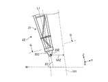
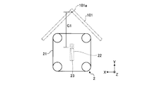
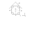
図17は、鉄塔に取り付けられた第1比較例に係る台棒の下端部を示す拡大図である。図18は、図17におけるG-G断面図である。図19は、鉄塔に取り付けられた本実施形態に係る台棒の下端部を示す拡大図である。図20は、図19におけるI-I断面図である。第1比較例に係る基部ユニット2Zは、本実施形態に係る基部アタッチメント22とは異なる基部アタッチメント22Zを備える。基部アタッチメント22Zに設けられた取付孔23Zは、X方向で見て中心線L1上にある。
第1比較例に係る基部ユニット2Z及び本実施形態に係る基部ユニット2は、同じ取付金具5を介して主柱材101に取り付けられている。このため、取付孔23Zから主柱材101の隅角部101aまでの距離G1Zは、取付孔23から主柱材101の隅角部101aまでの距離G1と同じである。図17に示すように、中心線L1が水平線Hとなす角度θZが大きくなると、基部ユニット2Zは、主柱材101に接する。基部ユニット2Zが主柱材101に接する時の角度θZをZ°とすると、角度θZの上限はZ°である。
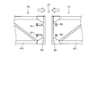
一方、本実施形態に係る基部ユニット2においては、取付孔23は、中心線L1に対してY方向に離れている。このため、仮に示す中心線L1が水平線Hに対してなす角度θ1(図19参照)が第1比較例のZ°に達したとしても、基部ユニット2は主柱材101に接しない。すなわち、図20に示すように、基部ユニット2と主柱材101との間には隙間が生じる。このため、角度θ1の上限は角度θZの上限(Z°)よりも大きくなる。本実施形態に係る台棒1によれば、第1比較例と比較して先端ユニット3の可動範囲が大きくなる。
図21は、鉄塔に取り付けられた第2比較例に係る台棒の一部を示す拡大図である。図22は、図21におけるJ-J断面図である。図23は、鉄塔に取り付けられた本実施形態に係る台棒の一部を示す拡大図である。図24は、図23におけるK-K断面図である。第2比較例に係る台棒1Yは、全ての中間ユニット4において主材411が中心線L1に平行である点で本実施形態と異なる。すなわち、台棒1Yは、主材411が中心線L1に対して傾斜した中間ユニット4(図13に示す中間ユニット4a及び中間ユニット4b)を備えない。台棒1Yは、第1比較例とは異なり、本実施形態と同様の基部ユニット2を有する。
図21及び図22に示すように、第2比較例においては、中心線L1が水平線Hとなす角度θYが大きくなると、基部ユニット2の上端部(基部ユニット2と中間ユニット4との間の境界部分)が主柱材101に接する。取付孔23が中心線L1よりも主柱材101側に位置するため、基部ユニット2の下端部よりも先に基部ユニット2の上端部が主柱材101に接する。台棒1Yが主柱材101に接する時の角度θYをY°とすると、角度θYの上限はY°である。Y°は、第1比較例のZ°よりも大きい。
また、角度θYが大きくなると、滑車82及び吊上ワイヤ71が先端ユニット3の下端部(先端ユニット3と中間ユニット4との間の境界部分)と接する。この時の角度θYをX°とする。滑車82及び吊上ワイヤ71が先端ユニット3に接すると、吊上ワイヤ71の動きが阻害される。このため、滑車82及び吊上ワイヤ71は先端ユニット3に接触しないことが望ましい。
一方、本実施形態に係る台棒1においては、基部ユニット2に、図13に示す中間ユニット4a及び中間ユニット4bが取り付けられている。このため、仮に中心線L1が水平線Hに対してなす角度θ2(図23参照)が第2比較例のY°に達したとしても、台棒1は主柱材101に接しない。すなわち、図24に示すように、台棒1と主柱材101との間には隙間が生じる。このため、角度θ2の上限は角度θYの上限(Y°)よりも大きくなる。本実施形態に係る台棒1によれば、第2比較例と比較して先端ユニット3の可動範囲が大きくなる。
また、本実施形態においては、先端ユニット3に図13に示す中間ユニット4a及び中間ユニット4bが取り付けられている。このため、角度θ2が第2比較例のX°に達したとしても、滑車82及び吊上ワイヤ71が先端ユニット3の下端部に接しない。本実施形態に係る台棒1によれば、第2比較例と比較して滑車82及び吊上ワイヤ71が先端ユニット3に接触しにくくなる。
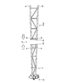
図25は、本実施形態に係る台棒の組み立て方法を示すフローチャートである。図26は、組み立てられる途中の本実施形態に係る台棒を示す図である。図27は、組み立てられる途中の本実施形態に係る台棒を示す図である。図28は、組み立てられる途中の本実施形態に係る台棒を示す図である。図29は、組み立てられる途中の本実施形態に係る台棒を示す図である。図30は、組み立てられる途中の本実施形態に係る台棒を示す図である。
台棒1は、鉄塔10の建設現場で組み立てられる。具体的には、工場等で予め組み立てられた基部ユニット2、先端ユニット3及び複数の中間ユニット4が、鉄塔10の建設現場に搬送される。基部ユニット2、先端ユニット3及び中間ユニット4の重量は、例えば45kg以下である。このため、基部ユニット2、先端ユニット3及び中間ユニット4は、それぞれ人力で搬送することができる。基部ユニット2、先端ユニット3及び複数の中間ユニット4は、鉄塔10の建設現場まで搬送された後、ボルト又はピンによって接合される。
まず基部ユニット2が中間ユニット4aにボルトで接合される(図25のステップST1)。具体的には、図26に示すように、中間ユニット4aのフランジ93と基部ユニット2のフランジ93を貫通する複数のボルト91及びナット92によって、基部ユニット2及び中間ユニット4aが接合される。
次に、先端ユニット3が中間ユニット4aにボルトで接合される(図25のステップST2)。具体的には、図27に示すように、中間ユニット4aのフランジ93と先端ユニット3のフランジ93を貫通する複数のボルト91及びナット92によって、先端ユニット3及び中間ユニット4aが接合される。
次に、2つの中間ユニット4がボルトで接合され、中間ユニットペア40が形成される(図25のステップST3)。具体的には、図28に示すように、2つの中間ユニット4のフランジ93を貫通する複数のボルト91及びナット92によって、2つの中間ユニット4が接合される。ステップST3において、4対の中間ユニット4が接合される。すなわち、4つの中間ユニットペア40が形成される。
次に、先端ユニット3が吊り上げられる(図25のステップST4)。例えば、図29に示すように、先端アタッチメント32に取り付けられたワイヤ75、及びワイヤ75に連結されたウインチによって先端ユニット3が吊り上げられる。先端ユニット3が吊り上げられると、先端ユニット3に接合された中間ユニット4aも吊り上げられる。このため、先端ユニット3及び中間ユニット4aが鉛直方向に沿う。
次に、先端ユニット3に接合された中間ユニット4aに中間ユニットペア40がピン64で接合される(図25のステップST5)。具体的には、図29に示すように、先端ユニット3に接合された中間ユニット4aの雄部材61が中間ユニットペア40の雌部材62に嵌められる。これと同時に、中間ユニット4aの雌部材62が中間ユニットペア40の雄部材61に嵌められる。そして、雄部材61及び雌部材62にピン64が挿入され、ピン64にロックピン65が挿入される。これにより、先端ユニット3に接合された中間ユニット4aと中間ユニットペア40との間にピンジョイント6が形成される。
次に、中間ユニットペア40同士がピンで接合される(図25のステップST6)。具体的には、図30に示すように、中間ユニットペア40の雄部材61が中間ユニットペア40の雌部材62に嵌められる。そして、雄部材61及び雌部材62にピン64が挿入され、ピン64にロックピン65が挿入される。これにより、4つの中間ユニットペア40が接合される。すなわち、隣接する中間ユニットペア40の間にピンジョイント6が形成される。例えば、1対の中間ユニットペア40の接合が終わった後、ワイヤ75が巻き取られ、組み立て途中の台棒1の高さが調節される。具体的には、中間ユニットペア40の長さ(3m)分のワイヤ75が巻き取られる。これにより、一定の高さでピン64による接合が行われるので、作業効率が向上する。
次に、基部ユニット2に接合された中間ユニット4aが中間ユニットペア40にピン64で接合される(図25のステップST7)。具体的には、図30に示すように、基部ユニット2に接合された中間ユニット4aの雄部材61が中間ユニットペア40の雌部材62に嵌められる。これと同時に、中間ユニット4aの雌部材62が中間ユニットペア40の雄部材61に嵌められる。そして、雄部材61及び雌部材62にピン64が挿入され、ピン64にロックピン65が挿入される。これにより、基部ユニット2に接合された中間ユニット4aと中間ユニットペア40との間にピンジョイント6が形成される。
以上のステップST1からステップST7によって、台棒1が完成する。部材を地面等に横向きに置いた状態で行われる工程は、ステップST1からステップST3までである。基部ユニット2の長さと中間ユニット4aの長さとの和、先端ユニット3の長さと中間ユニット4aの長さとの和、及び中間ユニットペア40の長さは、いずれも3mである。このため、台棒1の組み立てのために必要となる敷地の水平方向の長さは、3m程度である。本実施形態に係る台棒1の組み立て方法によれば、台棒1の組み立てに必要となるスペースを小さくすることができる。
なお、ステップST1からステップST7の順番は、上述した順番に限られず、適宜入れ替えることができる。ただし、ステップST2はステップST4より前である。また、ステップST3はステップST6より前である。また、ステップST1はステップST7より前である。例えば、ステップST2、ステップST4、ステップST3、ステップST5、ステップST6、ステップST1、ステップST7の順に進められてもよい。また、ステップST4において吊り上げられる対象は、必ずしも先端ユニット3でなくてもよく、基部ユニット2であってもよい。
なお、ボルトジョイント9及びピンジョイント6の配置は、適宜変更されてよい。例えば、台棒1の長さ及び鉄塔10の構成材102の重量等に応じて、ボルトジョイント9及びピンジョイント6の配置は変更される。例えば、第1ジョイントJ1、第2ジョイントJ2及び全ての第3ジョイントJ3がボルトジョイント9であってもよいし、第1ジョイントJ1、第2ジョイントJ2及び全ての第3ジョイントJ3がピンジョイント6であってもよい。
なお、基部アタッチメント22は、必ずしも取付孔23を備えていなくてもよい。例えば、基部アタッチメント22は、取付孔23に代えて、X方向に突出する連結部材を備えていてもよい。このような場合、基部アタッチメント22に設けられた連結部材が、取付金具5に設けられた取付孔に挿入されればよい。ただし、取付孔23に代えて設けられた連結部材の位置は、取付孔23の位置と同様に中心線L1から離れた位置である。
以上で説明したように、台棒1は、基部ユニット2と、先端ユニット3と、複数の中間ユニット4と、を備える。基部ユニット2は、鉄塔10の主柱材101の内側に取り付けられる基部アタッチメント22、及び基部アタッチメント22を通る水平方向に沿う回転軸Axを中心に基部アタッチメント22と共に回転することができる基部胴体21を有する。先端ユニット3には、支持ワイヤ72が取り付けられる。中間ユニット4は、基部ユニット2と先端ユニット3とを連結するための部材である。主柱材101は、上端部が下端部より鉄塔10の内側に位置するように傾斜している。回転軸Axは、基部胴体21の重心GP2を通り且つ基部胴体21の長手方向に沿う中心線L1に対して主柱材101側に位置する。基部ユニット2に隣接する中間ユニット4において、回転軸Ax及び中心線L1の両方に対して垂直な方向(Y方向)の幅は、基部ユニット2側に向かって小さくなっている。
これにより、台棒1が水平面に対してなす角度が大きくなっても、台棒1が主柱材101に接触しにくい。言い換えると、台棒1が水平面に対してなす角度が、従来技術における上限の角度(台棒が主柱材に接触する時の角度)になっても、台棒1と主柱材101との間には隙間が生じる。したがって、台棒1は、被搬送部材が移動できる範囲を大きくすることができる。
また、回転軸Axが中心線L1に対して主柱材101側に位置することにより、基部ユニット2の下端部よりも先に基部ユニット2と中間ユニット4との間の境界部分が主柱材101に接する可能性がある。これに対して、本実施形態においては基部ユニット2に隣接する中間ユニット4の幅が基部ユニット2に向かって小さくなっている。これにより、台棒1が水平面に対してなす角度が大きくなっても、基部ユニット2と中間ユニット4との間の境界部分が主柱材101に接触しにくい。したがって、台棒1は、被搬送部材が移動できる範囲を大きくすることができる。
また、台棒1において、中心線L1から回転軸Axまでの距離D1は、回転軸Ax及び中心線L1の両方に対して直交する方向(Y方向)における基部胴体21の最小幅(幅D3)の半分以下である。
これにより、台棒1が鉄塔10に取り付けられた時に基部アタッチメント22に生じる曲げモーメントが抑制される。したがって、基部アタッチメント22の破損がより防止される。
また、台棒1において、基部胴体21は、4つの主材211を備える。4つの主材211は、基部胴体21の長手方向(Z方向)から見てそれぞれ正方形29の頂点に配置されている。
これにより、基部胴体21が3つの主材211で構成されている場合に比較して、基部ユニット2の強度が向上しやすくなる一方で、中心線L1が主柱材101から遠くなる。このため、従来技術のように回転軸Axが中心線L1と重なる場合、台棒1が主柱材101に接触しやすい。これに対して、回転軸Axが中心線L1に対して主柱材101側に位置し且つ4つの主材211が正方形29の頂点に配置されることで、基部ユニット2の強度の向上と被搬送部材が移動できる範囲の拡大とが両立する。
(変形例)
図31は、変形例に係る基部ユニットを示す正面図である。変形例に係る台棒1Aの基部ユニット2Aは、上述した実施形態の基部アタッチメント22とは異なる基部アタッチメント22Aを備える。なお、上述した実施形態で説明したものと同じ構成要素には同一の符号を付して重複する説明は省略する。
図31は、変形例に係る基部ユニットを示す正面図である。変形例に係る台棒1Aの基部ユニット2Aは、上述した実施形態の基部アタッチメント22とは異なる基部アタッチメント22Aを備える。なお、上述した実施形態で説明したものと同じ構成要素には同一の符号を付して重複する説明は省略する。
基部アタッチメント22Aは、X軸に沿う取付孔23Aを有する板状部材である。図31に示すように、取付孔23Aは、中心線L1に対してY方向に離れている。中心線L1から取付孔23Aまでの距離D1Aは、幅D3の半分より大きく且つ幅D2の半分より小さい。これにより、上述した実施形態に比較して、基部ユニット2Aと主柱材101との間に隙間が生じやすくなる。このため、先端ユニット3の可動範囲が大きくなる。
1、1A 台棒
10 鉄塔
101 主柱材
101a 隅角部
102 構成材
2、2A 基部ユニット
21 基部胴体
211 主材
212 斜材
22、22A 基部アタッチメント
23、23A 取付孔
3 先端ユニット
31 先端胴体
311 主材
312 斜材
32 先端アタッチメント
321 固定部
322 シャフト
323 ナット
324 回転部
3241 ウィング
325 スリーブ
326 軸受
329 フランジ
4、4a、4b 中間ユニット
40 中間ユニットペア
41 中間胴体
411 主材
412 斜材
5 取付金具
51 インナープレート
511 ボルト
512 ナット
52 アウタープレート
521 アイボルト
522 ナット
54 台棒連結部
541 ボルト
542 ナット
543 ホールドプレート
545 連結部材
546 ナット
55 滑車連結部
553 ホールドプレート
555 ボルト
556 ナット
6 ピンジョイント
61 雄部材
61h 孔
62 雌部材
62h 孔
64 ピン
641 基部
642 抜止部
643 テーパー部
644 孔
65 ロックピン
71 吊上ワイヤ
72 支持ワイヤ
75 ワイヤ
81、82、83 滑車
9 ボルトジョイント
91 ボルト
92 ナット
Ax 回転軸
GP2、GP3、GP4 重心
J1 第1ジョイント
J2 第2ジョイント
J3 第3ジョイント
L1 中心線
L2 直線
10 鉄塔
101 主柱材
101a 隅角部
102 構成材
2、2A 基部ユニット
21 基部胴体
211 主材
212 斜材
22、22A 基部アタッチメント
23、23A 取付孔
3 先端ユニット
31 先端胴体
311 主材
312 斜材
32 先端アタッチメント
321 固定部
322 シャフト
323 ナット
324 回転部
3241 ウィング
325 スリーブ
326 軸受
329 フランジ
4、4a、4b 中間ユニット
40 中間ユニットペア
41 中間胴体
411 主材
412 斜材
5 取付金具
51 インナープレート
511 ボルト
512 ナット
52 アウタープレート
521 アイボルト
522 ナット
54 台棒連結部
541 ボルト
542 ナット
543 ホールドプレート
545 連結部材
546 ナット
55 滑車連結部
553 ホールドプレート
555 ボルト
556 ナット
6 ピンジョイント
61 雄部材
61h 孔
62 雌部材
62h 孔
64 ピン
641 基部
642 抜止部
643 テーパー部
644 孔
65 ロックピン
71 吊上ワイヤ
72 支持ワイヤ
75 ワイヤ
81、82、83 滑車
9 ボルトジョイント
91 ボルト
92 ナット
Ax 回転軸
GP2、GP3、GP4 重心
J1 第1ジョイント
J2 第2ジョイント
J3 第3ジョイント
L1 中心線
L2 直線
Claims (3)
- 鉄塔の主柱材の内側に取り付けられる基部アタッチメント、及び前記基部アタッチメントを通る水平方向に沿う回転軸を中心に前記基部アタッチメントと共に回転することができる基部胴体を有する基部ユニットと、
支持ワイヤが取り付けられる先端ユニットと、
前記基部ユニットと前記先端ユニットとを連結するための複数の中間ユニットと、
を備え、
前記主柱材は、上端部が下端部より前記鉄塔の内側に位置するように傾斜しており、
前記回転軸は、前記基部胴体の重心を通り且つ前記基部胴体の長手方向に沿う中心線に対して前記主柱材側に位置し、
前記基部ユニットに隣接する前記中間ユニットにおいて、前記回転軸及び前記中心線の両方に対して垂直な方向の幅は、前記基部ユニット側に向かって小さくなっている
台棒。 - 前記中心線から前記回転軸までの距離は、前記回転軸及び前記中心線の両方に対して直交する方向における前記基部胴体の最小幅の半分以下である
請求項1に記載の台棒。 - 前記基部胴体は、4つの主材を備え、
前記4つの主材は、前記基部胴体の長手方向から見てそれぞれ正方形の頂点に配置されている
請求項1又は2に記載の台棒。
Priority Applications (1)
| Application Number | Priority Date | Filing Date | Title |
|---|---|---|---|
| JP2018500592A JP6328360B1 (ja) | 2016-07-26 | 2017-06-30 | 台棒 |
Applications Claiming Priority (2)
| Application Number | Priority Date | Filing Date | Title |
|---|---|---|---|
| PCT/JP2016/071859 WO2018020574A1 (ja) | 2016-07-26 | 2016-07-26 | 台棒 |
| JPPCT/JP2016/071859 | 2016-07-26 |
Publications (1)
| Publication Number | Publication Date |
|---|---|
| WO2018020958A1 true WO2018020958A1 (ja) | 2018-02-01 |
Family
ID=59969410
Family Applications (2)
| Application Number | Title | Priority Date | Filing Date |
|---|---|---|---|
| PCT/JP2016/071859 Ceased WO2018020574A1 (ja) | 2016-07-26 | 2016-07-26 | 台棒 |
| PCT/JP2017/024210 Ceased WO2018020958A1 (ja) | 2016-07-26 | 2017-06-30 | 台棒 |
Family Applications Before (1)
| Application Number | Title | Priority Date | Filing Date |
|---|---|---|---|
| PCT/JP2016/071859 Ceased WO2018020574A1 (ja) | 2016-07-26 | 2016-07-26 | 台棒 |
Country Status (2)
| Country | Link |
|---|---|
| JP (2) | JP6204629B1 (ja) |
| WO (2) | WO2018020574A1 (ja) |
Families Citing this family (1)
| Publication number | Priority date | Publication date | Assignee | Title |
|---|---|---|---|---|
| JP7193374B2 (ja) * | 2019-02-20 | 2022-12-20 | 株式会社タワーライン・ソリューション | 台棒の取付金具及び当該取付金具を使用した台棒の取り付け方法 |
Citations (3)
| Publication number | Priority date | Publication date | Assignee | Title |
|---|---|---|---|---|
| JPS62222993A (ja) * | 1986-03-22 | 1987-09-30 | 三和テッキ株式会社 | 鉄塔建設用簡易クレ−ン及びこれを用いた鉄塔建設方法 |
| JP2000291261A (ja) * | 1999-04-09 | 2000-10-17 | Sanwa Tekki Corp | 鉄塔建設用ブーム |
| JP2014065572A (ja) * | 2012-09-26 | 2014-04-17 | Kobelco Cranes Co Ltd | 起伏部材の案内ブラケット、及びジブの連結方法 |
Family Cites Families (1)
| Publication number | Priority date | Publication date | Assignee | Title |
|---|---|---|---|---|
| JP2005335828A (ja) * | 2004-05-24 | 2005-12-08 | Ishikawajima Transport Machinery Co Ltd | クライミングクレーン |
-
2016
- 2016-07-26 WO PCT/JP2016/071859 patent/WO2018020574A1/ja not_active Ceased
- 2016-07-26 JP JP2017514590A patent/JP6204629B1/ja active Active
-
2017
- 2017-06-30 JP JP2018500592A patent/JP6328360B1/ja active Active
- 2017-06-30 WO PCT/JP2017/024210 patent/WO2018020958A1/ja not_active Ceased
Patent Citations (3)
| Publication number | Priority date | Publication date | Assignee | Title |
|---|---|---|---|---|
| JPS62222993A (ja) * | 1986-03-22 | 1987-09-30 | 三和テッキ株式会社 | 鉄塔建設用簡易クレ−ン及びこれを用いた鉄塔建設方法 |
| JP2000291261A (ja) * | 1999-04-09 | 2000-10-17 | Sanwa Tekki Corp | 鉄塔建設用ブーム |
| JP2014065572A (ja) * | 2012-09-26 | 2014-04-17 | Kobelco Cranes Co Ltd | 起伏部材の案内ブラケット、及びジブの連結方法 |
Also Published As
| Publication number | Publication date |
|---|---|
| JP6204629B1 (ja) | 2017-09-27 |
| JP6328360B1 (ja) | 2018-05-23 |
| WO2018020574A1 (ja) | 2018-02-01 |
| JPWO2018020574A1 (ja) | 2018-07-26 |
| JPWO2018020958A1 (ja) | 2018-07-26 |
Similar Documents
| Publication | Publication Date | Title |
|---|---|---|
| JP4843709B2 (ja) | 大空間建物の構築方法 | |
| JP6004537B2 (ja) | ジブ | |
| CN113233346B (zh) | 回转总成及其上支座、回转总成组件和塔式起重机 | |
| JP6328360B1 (ja) | 台棒 | |
| CN204024090U (zh) | 一种劲性柱校正总成 | |
| JP7021474B2 (ja) | ラチス構造物の製造方法 | |
| JP6188287B2 (ja) | 伸縮管の固定装置 | |
| JP6204630B1 (ja) | 台棒及び台棒の組み立て方法 | |
| WO2022001622A1 (zh) | 盾构机的盾尾的安装方法 | |
| CN105464213B (zh) | 一种大跨度预应力圆顶结构及其制作方法 | |
| JP6210608B1 (ja) | 支保工 | |
| JP2012001997A (ja) | 折り畳み式支保工 | |
| JP2008308899A (ja) | 油圧シリンダの連結構造及びそれを備えた建設機械 | |
| US20240183375A1 (en) | Connecting device for securing two beams to each other, a method for using the connecting device, and tower including the connecting device | |
| JP7555596B2 (ja) | セントルフォーム側板におけるカラーの固定方法及びセントルフォーム側板の反転装置 | |
| KR20120071002A (ko) | 각형 강관의 이음 장치 및 그 이음 방법 | |
| JP6837885B2 (ja) | ピン結合装置 | |
| CN102310845B (zh) | 一种轮式起重机及其承重结构 | |
| JP6884262B2 (ja) | 巻上機組立治具及び巻上機組立治具を用いた巻上機組立方法 | |
| CN104060697B (zh) | 一种连接杆件的接头装置 | |
| JP6805036B2 (ja) | ピン結合装置 | |
| JP6622514B2 (ja) | 建設機械およびカーボディウエイトの取付方法 | |
| CN115583561B (zh) | 一种起重机回转装置的组装方法 | |
| CN220201224U (zh) | 一种塔式起重机塔身调整节 | |
| JP7330007B2 (ja) | 制振装置 |
Legal Events
| Date | Code | Title | Description |
|---|---|---|---|
| ENP | Entry into the national phase |
Ref document number: 2018500592 Country of ref document: JP Kind code of ref document: A |
|
| 121 | Ep: the epo has been informed by wipo that ep was designated in this application |
Ref document number: 17833967 Country of ref document: EP Kind code of ref document: A1 |
|
| NENP | Non-entry into the national phase |
Ref country code: DE |
|
| 122 | Ep: pct application non-entry in european phase |
Ref document number: 17833967 Country of ref document: EP Kind code of ref document: A1 |