WO2018012544A1 - 樹脂成型品の接合方法 - Google Patents
樹脂成型品の接合方法 Download PDFInfo
- Publication number
- WO2018012544A1 WO2018012544A1 PCT/JP2017/025431 JP2017025431W WO2018012544A1 WO 2018012544 A1 WO2018012544 A1 WO 2018012544A1 JP 2017025431 W JP2017025431 W JP 2017025431W WO 2018012544 A1 WO2018012544 A1 WO 2018012544A1
- Authority
- WO
- WIPO (PCT)
- Prior art keywords
- molded product
- resin
- molded article
- irradiation
- ultraviolet light
- Prior art date
- Legal status (The legal status is an assumption and is not a legal conclusion. Google has not performed a legal analysis and makes no representation as to the accuracy of the status listed.)
- Ceased
Links
Images




Classifications
-
- B—PERFORMING OPERATIONS; TRANSPORTING
- B29—WORKING OF PLASTICS; WORKING OF SUBSTANCES IN A PLASTIC STATE IN GENERAL
- B29C—SHAPING OR JOINING OF PLASTICS; SHAPING OF MATERIAL IN A PLASTIC STATE, NOT OTHERWISE PROVIDED FOR; AFTER-TREATMENT OF THE SHAPED PRODUCTS, e.g. REPAIRING
- B29C65/00—Joining or sealing of preformed parts, e.g. welding of plastics materials; Apparatus therefor
- B29C65/02—Joining or sealing of preformed parts, e.g. welding of plastics materials; Apparatus therefor by heating, with or without pressure
- B29C65/14—Joining or sealing of preformed parts, e.g. welding of plastics materials; Apparatus therefor by heating, with or without pressure using wave energy, i.e. electromagnetic radiation, or particle radiation
Definitions
- the present invention relates to a method for joining resin molded products in which a resin molded product is joined by irradiating light.
- a three-dimensional hollow body made of a resin composition and having a hollow portion formed therein is used for a flow path of an analytical instrument, piping parts, a case cover of an engine control unit (ECU), and the like.
- ECU engine control unit
- a plurality of constituent members of a resin molded product made of a resin composition are joined to each other.
- Patent Documents 1-4 and Non-Patent Document 1 techniques for processing and bonding resin molded products with vacuum ultraviolet light (VUV) are provided (see Patent Documents 1-4 and Non-Patent Document 1). According to this technique, it takes several minutes to several tens of minutes to join the resin molded product, but the deformation of the bonded resin molded product is small, and the deformation of the hollow portion is also small.
- Patent Documents 1 and 2 and Non-Patent Document 1 assume that the resin molded product is made of an amorphous resin such as polymethyl methacrylate (PMMA) resin or cyclic olefin resin, and the bonding strength is 1 MPa or less.
- Patent Documents 3 and 4 assume silicone adhesion.
- a resin having high heat resistance, robustness and stability such as polybutylene terephthalate (PBT)
- PBT polybutylene terephthalate
- a crystalline thermoplastic resin such as a resin or polyphenylene sulfide (PPS) resin can be used.
- the present invention is proposed in view of the above circumstances, and even when a resin molded product made of a resin composition having a relatively high heat resistance is joined, the deformation of the resin molded product or the deformation of the hollow portion It is an object of the present invention to provide a method for joining resin molded products that can keep the joint strength small and obtain high joint strength (1 MPa or more).
- a method for joining resin molded products is a method for joining resin molded products made of a resin composition, and provides a first molded product and a second molded product.
- the first molded product and the second molded product are irradiated such that predetermined ultraviolet irradiation areas are respectively irradiated on predetermined irradiation regions on the surfaces of the first molded product and the second molded product, and the irradiation regions are opposed to each other.
- the resin composition comprising: The Vicat softening temperature is 140 ° C. or higher, and the first molded product and the second molded product are joined at a pressure of 10 MPa or higher.
- the vacuum ultraviolet light may be applied to the first molded product and the second molded product for a time of more than 0 minutes and not more than 15 minutes.
- the resin composition may be a thermoplastic crystalline resin.
- the thermoplastic crystalline resin may include polyacetal, polybutylene terephthalate, polyethylene terephthalate, polyphenylene sulfide, or a liquid crystal polymer.
- Each of the first molded product and the second molded product may include a facing surface on the surface, and the irradiation region may include at least a part of the facing surface.
- the facing surface refers to a surface that can be opposed and contacted, such as flat surfaces, for example, even if the surface has irregularities, the concave portion of the first molded product and the convex portion of the second molded product (or If the convex part of a 1st molded product and the recessed part of a 2nd molded product) can respond
- the present invention even a resin composition having a relatively high heat resistance can be bonded while suppressing deformation of the resin molded product, in particular, deformation of the hollow portion in the resin molded product constituting the three-dimensional hollow body. Moreover, the joined resin molded product has high joining strength.
- the resin composition has a relatively high heat resistance such as a Vicat softening temperature of 140 ° C. or higher.
- the resin composition may be a thermoplastic crystalline resin.
- the Vicat softening temperature in the present invention refers to a value measured in accordance with ISO 306 B50 method (test load 10 N and heating rate 50 ° C./h).
- thermoplastic crystalline resin for example, polyacetal (POM), polybutylene terephthalate (PBT), polyethylene terephthalate (PET), polyphenylene sulfide (PPS), or liquid crystal polymer (LCP) may be used.
- POM polyacetal
- PBT polybutylene terephthalate
- PET polyethylene terephthalate
- PPS polyphenylene sulfide
- LCP liquid crystal polymer
- Thermoplastic crystalline resins are generally opaque, but may be translucent or transparent for resins with low crystallinity.
- Glass fiber may be added to the thermoplastic crystalline resin.
- you may add the compound and elastomer which have a polar functional group to a crystalline thermoplastic resin.
- the compound having a polar functional group may be an epoxy compound such as a bisphenol A epoxy compound, a bisphenol F type epoxy compound, a novolac type epoxy compound, an aliphatic type epoxy compound, a glycidylamine type epoxy compound, an oxazoline compound, an oxazine It may be a compound, a carbodiimide compound, or an aziridine compound.
- the elastomer may be an olefin elastomer such as an ethylene ethyl acrylate copolymer or an ethylene glycidyl methacrylate copolymer, an acrylic elastomer (for example, an acrylic core shell polymer), a urethane elastomer, a styrene elastomer, or a polyester elastomer. Further, it may be a diene elastomer.
- the first molded product and the second molded product made of the resin composition are used, and these are joined to each other.
- the first molded product and the second molded product include opposing surfaces joined to each other on the surface, and these opposing surfaces are formed in corresponding shapes.
- the opposing surfaces of the first molded product and the second molded product may be formed substantially flat.
- the opposing surface is a surface having irregularities, the concave portion of the first molded product and the convex portion of the second molded product (or the convex portion of the first molded product and the concave portion of the second molded product) are in close contact with each other. Any surface that can be used.
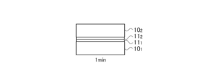
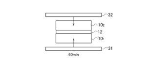
- FIG. 1A to 1C are diagrams schematically illustrating a series of steps of the present embodiment.
- the first prepared molded article 10 1 is irradiated with vacuum ultraviolet (VUV) light to the first molded product 10 1 of the irradiated surface 10 1 a using a vacuum ultraviolet light irradiation device 20.
- vacuum ultraviolet light refers to ultraviolet light having a wavelength of 200 nm or less, and is not necessarily irradiated in vacuum, but ultraviolet light in the wavelength region has a large absorption by air. Therefore, when irradiating in the air, it is necessary to shorten the distance that the vacuum ultraviolet light propagates.
- the vacuum ultraviolet light irradiation apparatus 20 includes a light source 21 such as an Xe excimer lamp, and a reflection plate 22 that reflects light emitted from the light source 21 toward an irradiation object.
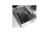
- FIG. 2 is a photograph showing an example of a vacuum ultraviolet light irradiation apparatus. The vacuum ultraviolet light irradiation apparatus shown in this photograph can irradiate vacuum ultraviolet light from the opening formed on the upper surface of the housing toward the upper part.
- the first molded product 10 1 has a substantially flat illumination surface 10 1 a.
- the vacuum ultraviolet light irradiation for 2 minutes toward the irradiated surface 10 1 a of the first molded product 10 1 from the vacuum ultraviolet light irradiation device 20 Such irradiation treatment, the first molded product 10 1 of the irradiated surface 10 1 a, the processing layer 11 1 properties has changed in the resin composition is formed from the irradiated surface 10 1 a to a predetermined depth.
- the second providing a molded article 10 2 and the vacuum ultraviolet light irradiation for 2 minutes towards the vacuum ultraviolet light irradiation device 20 in the second molded product 10 second irradiation surface 10 2 a The second molded product 10 2 is directed to the irradiation surface 10 2 a first molded product 10 1 and the opposing surface to be bonded.
- the processing layer 11 2 that property changes of the resin composition is formed from the irradiated surface 10 2 a to a predetermined depth.
- irradiation of vacuum ultraviolet light to the first molded product 10 1 and the second molding 10 2 is not limited to two minutes, even 15 minutes or less than 0 minutes Good. Moreover, the time of 5 seconds or more and 11 minutes or less (for example, 30 seconds or more and 10 minutes or less, or 1 minute or more and 7 minutes or less) may be sufficient.
- the rather bonding strength may be reduced, it is preferable irradiation of vacuum ultraviolet light to the first molded product 10 1 and the second molding 10 2 is within a predetermined time.
- the vacuum ultraviolet light irradiation first molded product 10 1 and to the second molding 10 2 may be performed simultaneously using the same vacuum ultraviolet light irradiation device. Moreover, contrary to the above order, performs irradiation of vacuum ultraviolet light to the second molded product 10 2 above, may be irradiated with vacuum ultraviolet light followed by the first molded product 10 1.
- the first molded product 10 1 of the irradiated surface 10 1 a and the second molded product 10 second irradiation surface 10 2 a are in contact with opposed first molded product 10 1 and the second the positioning of the molded article 10 2. That is, the first molded product 10 1 of the opposing surface and the second molding 10 second opposing surfaces to be in close contact with the corresponding.
- the positioned state, the first molded product 10 1 generally planar illuminated surface 10 1 a and the second substantially planar illuminated surface 10 2 a of the molded article 10 2 are in contact throughout its substantially from each other.
- the first press member 31 and the second press member 32, the first molded product 10 1 of the irradiated surface 10 1 a and the pressure above 10MPa in the direction of pressing together the irradiated surface 10 2 a of the second molded product 10 2 Add What is necessary is just to adjust this pressure suitably in the range of 10 Mpa or more.
- the upper limit of the pressure is not particularly limited, but when pressing at an extremely high pressure, deformation of the molded product may cause a problem, and therefore, it is preferably 60 MPa or less, and may be, for example, 30 MPa.
- the pressurization time may be appropriately adjusted within a range of 2 minutes or more and 120 minutes or less, and for example, pressurization may be performed over 60 minutes.
- the first press member 31 and the second press member 32 may be provided with a heating device, by the heating apparatus, the irradiation surface 10 1 a and the irradiation surface of the second molded product 10 2 of first molded product 10 1 10 2 a may be heated. May be appropriately adjusted within the range from 50 ° C. of the melting point of the resin according to the resin temperature at the irradiated surface 10 2 a of the first molded product 10 1 of the irradiated surface 10 1 a and the second molded product 10 2 are used, for example, 120 You may heat so that it may maintain at ° C. As a guide, it may be adjusted in the range of 0.5 to 2 times the deflection temperature under load of the resin to be joined.
- the deflection temperature under load in the present invention refers to a value measured under a load of 1.8 MPa in accordance with ISO 75-1 and 2.
- first molded product 10 1 of the treatment layer 11 1 and the processing layer 11 of the second molded product 10 2 fused, so to form a single bonding layer 12. That is, the first molded product 10 1 and the second molding 10 2 are linked fused together at respective opposing surfaces. Accordingly, the first molded product 10 1 and the second molding 10 2 is integrally connected through a bonding layer 12, so constituting a single molded product (for example, a three-dimensional hollow bodies).
- Bonding layer 12 is first molded product 10 1 of the treatment layer 11 1 and the treatment layer 11 of the second molded product 10 2 activated by the vacuum ultraviolet light, fused by a process of heat and pressure over a predetermined time It is a thing.
- the connection of the bonding layer 12 by the first molded product 10 1 and the second molding 10 2 are mechanically robust, which is chemically stable.
- first molded product 10 1 made of a resin composition °C as above have a relatively high heat resistance and a second molded product 10 2 Even so, it can be reliably bonded.
- This resin composition may be made of a thermoplastic crystalline resin.
- This embodiment has high heat resistance (for example, Vicat softening temperature of 140 ° C. or higher), and has a robust and stable property, such as polyacetal (POM) resin, polybutylene terephthalate (PBT) resin, polyethylene terephthalate (PET) resin.
- a thermoplastic crystalline resin such as polyphenylene sulfide (PPS) resin or liquid crystal polymer (LCP) can be used.
- PPS polyphenylene sulfide
- LCP liquid crystal polymer
- Such a thermoplastic crystalline resin can be used for production of a molded product (particularly a three-dimensional hollow body) to which heat or a large mechanical stress is applied over a long period of time, such as a water pump component.
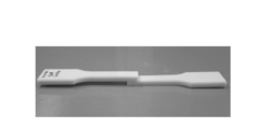
- FIG. 3 is a photograph showing a bonding test piece.
- bonding test pieces as shown in the photograph of FIG. 3 are used.
- Joining test pieces were made of tensile test pieces Type 1A conforming to ISO 3167 using various resin compositions, then cut into two equal parts at the center in the longitudinal direction, and 10 mm from the cut ends were overlapped as joining areas. Yes.
- two bonding test pieces are mounted to be bonded to each other in the bonding region.
- FIG. 4 is a graph showing the relationship between irradiation time and bonding strength in a PBT resin composition. This graph shows the result of measuring the bonding strength using a tensile tester in accordance with ISO527-1 and 2 using a bonding test piece bonded in accordance with the series of steps described in FIGS. 1A to 1C.
- the ultraviolet light vacuum ultraviolet light having a wavelength of 172 nm and an illuminance of 6 mW / cm 2 was used, and the bonding test piece positioning step shown in FIG. 1B was performed within 5 minutes from the end of the irradiation of the vacuum ultraviolet light.
- the heating and pressurizing steps shown in FIG. 1C were performed at a temperature of 120 ° C. and a pressure of 30 MPa for 1 hour.
- the broken line a in FIG. 4 is a polybutylene terephthalate (PBT) resin (Dulanex (registered trademark) 3300 manufactured by Wintech Polymer Co., Ltd., Vicat) reinforced with 30% by mass of glass fiber in both the first molded product and the second molded product.
- PBT polybutylene terephthalate
- the bonding strength of a bonding test piece having a softening temperature of 214 ° C., a deflection temperature under load of 213 ° C., and a melting point of 224 ° C. is shown.
- the measured value b is obtained by adding a small amount of epoxy resin to PBT resin reinforced with 30% by mass of glass fiber.
- These PBT resins reinforced with 30% glass fiber and those added with a small amount of epoxy resin have a Vicat softening temperature of 140 ° C. or higher.
- the PBT resin reinforced with 30% glass fiber mass has a certain bonding strength in the region where the irradiation time exceeds 0 minutes, and reaches the maximum bonding strength of 9.3 MPa in the irradiation time of 2 minutes. did.
- the measured value b is a bisphenol A type epoxy resin (Mitsubishi Chemical) in PBT resin (Juranex (registered trademark) 3300 manufactured by Wintech Polymer Co., Ltd.) reinforced with 30% by mass of glass fiber in both the first molded product and the second molded product. It is the joint strength of a joint test piece made of a composition (Vicat softening temperature 215 ° C., load deflection temperature 209 ° C., melting point 224 ° C.) to which 1.5% by mass of Epicoat (registered trademark) JER1004K) manufactured by Co., Ltd. is added.
- the irradiation time is 2 minutes when the bonding strength of the 30% glass fiber reinforced PBT resin shown in FIG. In the irradiation time of 2 minutes, the bonding strength of 30% glass fiber reinforced PBT resin added with epoxy resin is 10.0 MPa, which is higher than 9.3 MPa of 30% glass fiber reinforced PBT resin not added with epoxy resin. Strength increased.
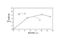
- FIG. 5 is a graph showing the relationship between irradiation time and bonding strength in the PPS resin composition.
- a wavelength of 172 nm is applied to the joining region of the joining test piece according to the series of steps described with reference to FIGS. 1A to 1C.
- Irradiate vacuum ultraviolet light with an illuminance of 6 mW / cm 2 and position the bonding test piece within 5 minutes from the end of irradiation, the broken line c is a temperature of 200 ° C. and a pressure of 30 MPa, the measurement value d is 160 ° C. and a pressure of 30 MPa, respectively. They were joined together by heating and pressing for 1 hour. Thereafter, the bonding strength of the bonded bonding tester was measured by a tensile tester in accordance with ISO527-1,2.
- the broken line c is a composition in which 30% by mass of glass fiber is added to polyphenylene sulfide (PPS) resin (Durafide (registered trademark) 0220A9 manufactured by Polyplastics Co., Ltd.) for both the first molded product and the second molded product (load deflection). Temperature 265 ° C., melting point 280 ° C.).
- the measured value d is an elastomer (Sumitomo Chemical Co., Ltd.) containing 30% by mass of glass fiber and PLS resin (Durafide (registered trademark) 0220A9, manufactured by Polyplastics Co., Ltd.) for both the first molded product and the second molded product.
- the irradiation time is constant in a region exceeding 0 minutes (particularly 2 minutes or more). Bonding strength was ensured.
- the molded article which consists of a composition which added 30 mass% of glass fibers and the elastomer containing a glycidyl group to PPS resin, compared with the broken line c in irradiation time 2 minutes, as shown in the measured value d. Even when the pressure was applied under a low heating temperature, the bonding strength was remarkably increased.
- FIG. 6 is a graph showing the relationship between irradiation time and bonding strength in the POM resin composition.
- a wavelength of 172 nm is applied to the bonding region of the bonding test piece according to the series of steps described in FIGS. 1A to 1C.
- the sample was irradiated with vacuum ultraviolet light having an illuminance of 6 mW / cm 2 , the bonding test piece was positioned within 5 minutes from the end of irradiation, and bonded to each other by heating and pressurizing at a temperature of 140 ° C. and a pressure of 15 MPa for 1 hour. Thereafter, the bonding strength of the bonded bonding tester was measured by a tensile tester in accordance with ISO527-1,2.
- both the first molded product and the second molded product are made of POM resin (Duracon (registered trademark) M90-44 manufactured by Polyplastics Co., Ltd.) and polyurethane resin (Rezamin P-4088 manufactured by Dainichi Seika Kogyo Co., Ltd.). It consists of a composition added with 13% by mass (load deflection temperature 82 ° C., melting point 165 ° C.). The Vicat softening temperature of this POM resin composition is 140 ° C. or higher.
- FIG. 7 shows the joining region of the joining test piece according to the series of steps described in FIGS. 1A to 1C using joining test pieces made of the LCP resin composition described below as the first molded product and the second molded product.
- the bonding test piece is positioned within 5 minutes from the end of irradiation, and heated and pressed at a temperature of 120 ° C. and a pressure of 15 MPa for 1 hour to bond each other. did. Thereafter, the bonding strength of the bonded bonding tester was measured by a tensile tester in accordance with ISO527-1,2.
- the broken line f is composed of a composition in which a liquid crystal polymer (LCP) having a melting point of about 280 ° C. is reinforced with 30% by mass of glass fiber (a deflection temperature under load of 240 ° C. and a melting point of 280 ° C.) in both the first molded product and the second molded product. It is.
- the Vicat softening temperature of this LCP composition is 140 ° C. or higher.
- both the first molded product and the second molded product are similar to the broken line a in FIG. 4 except that the ultraviolet light is irradiated only on the first molded product and not on the second molded product.
Landscapes
- Physics & Mathematics (AREA)
- Health & Medical Sciences (AREA)
- Electromagnetism (AREA)
- Toxicology (AREA)
- Engineering & Computer Science (AREA)
- Mechanical Engineering (AREA)
- Lining Or Joining Of Plastics Or The Like (AREA)
- Blow-Moulding Or Thermoforming Of Plastics Or The Like (AREA)
Abstract
比較的高い耐熱性を有する樹脂成型品について、樹脂成型品の変形や中空部の変形を小さく抑え、十分な接合強度が得られるように接続する。樹脂組成物からなる樹脂成型品を接合する接合方法であって、第1成型品101及び第2成型品102を提供し、第1成型品101及び第2成型品102の表面の所定の照射面101a、102aに真空紫外光をそれぞれ照射し、照射面101a、102aが対向して接触するように、第1成型品101及び第2成型品102を位置決めし、第1成型品101及び第2成型品102がそれぞれの照射面101a、102aで接合するように、第1成型品101及び第2成型品102を加圧し、樹脂組成物はビカット軟化温度140℃以上であり、第1成型品101及び第2成型品102は10MPa以上の圧力で接合する。
Description
本発明は、光線を照射して樹脂成型品を接合する樹脂成型品の接合方法に関する。
従来、分析機器の流路、配管部品、エンジンコントロールユニット(ECU)のケースカバー等に、樹脂組成物によって作製され、内部に中空部が形成された三次元中空体が利用されている。三次元中空体の多くは、樹脂組成物でなる樹脂成型品の複数の構成部材が、互いに接合されて構成されている。
樹脂成型品の構成部材を接合するためには、接着剤や熱溶着など、各種の接合技術が提供されている。ただし、樹脂成型品を接着剤で接合する技術は、樹脂成型品を変形させることなく接合することができるが、一般的に接着剤の硬化には数時間かかるため生産性に劣る上、接着剤が中空部に漏出して溝が埋没するといった問題から微細な流路部品の接合には適さないものであった。そして、樹脂成型品を熱溶着する技術は、数分で接合することが可能であるが、接合した樹脂成型品にバリが発生したり、中空部が熱変形したりすることがあった。
また、真空紫外光(VUV)により樹脂成型品を処理して接合する技術が提供されている(特許文献1-4、非特許文献1を参照)。この技術によると、樹脂成型品の接合に数分から数十分程度の時間を要するが、接合した樹脂成型品の変形は小さく、中空部の変形も小さい。特許文献1、2、非特許文献1は、樹脂成型品にポリメタクリル酸メチル(PMMA)樹脂や環状オレフィン樹脂等の非晶性樹脂でなるものを想定し、接合強度は1MPa以下である。特許文献3、4は、シリコーン接着を想定している。
谷口義尚、他4名、「光表面活性化によるシクロオレフィンポリマーの接合:接合強度評価とマイクロ流路への応用」、表面技術、表面技術協会、2014、第65巻、第5号、p.36-41
一方、ウォーターポンプ部品等の長期間にわたり熱や大きな機械的応力が加わる成型品(特に三次元中空体)には、耐熱性が高く堅牢で安定した性質を有する樹脂、例えばポリブチレンテレフタレート(PBT)樹脂やポリフェニレンサルファイド(PPS)樹脂のような結晶性の熱可塑性樹脂を利用することができる。また、そのような樹脂でなる樹脂成型品を接合することにより三次元中空体を作製する際には、接合による樹脂成型品の変形が小さく、中空部の変形も小さくすることが求められる。
前述の真空紫外光で樹脂成型品を処理して接合する技術は、樹脂成型品の変形や中空部の変形を小さく抑えることができたが、非晶性樹脂でなる樹脂成型品の接合やシリコーン接着剤の硬化を想定したものであった。しかし、例えばビカット軟化温度140℃以上のように比較的高い耐熱性を有する樹脂、特に結晶性の熱可塑性樹脂を接合する際には、十分な接合強度を確保することができなった。
本発明は、上述の実情に鑑みて提案されるものであって、比較的高い耐熱性を有する樹脂組成物でなる樹脂成型品を接合する場合についても、樹脂成型品の変形や中空部の変形を小さく抑えることができ、高い接合強度(1MPa以上)が得られるような樹脂成型品の接合方法を提供することを目的とする。
上述の課題を解決するために、本発明に係る樹脂成型品の接合方法は、樹脂組成物からなる樹脂成型品を接合する接合方法であって、第1成型品及び第2成型品を提供し、前記第1成型品及び前記第2成型品の表面の所定の照射領域に真空紫外光をそれぞれ照射し、前記照射領域が対向して接触するように、前記第1成型品及び前記第2成型品を位置決めし、前記第1成型品及び前記第2成型品がそれぞれの照射領域で接合するように、前記第1成型品及び前記第2成型品を加圧することを含み、前記樹脂組成物はビカット軟化温度140℃以上であり、前記第1成型品及び前記第2成型品は10MPa以上の圧力で接合する。
前記真空紫外光は、前記第1成型品及び前記第2成型品に0分を超え15分以下の時間にわたり照射してもよい。前記樹脂組成物は、熱可塑性結晶性樹脂でなってもよい。前記熱可塑性結晶性樹脂は、ポリアセタール、ポリブチレンテレフタレート、ポリエチレンテレフタレート、ポリフェニレンサルファイド又は液晶ポリマーを含んでもよい。前記第1成型品及び前記第2成型品はそれぞれ表面に対向面を含み、前記照射領域は前記対向面の少なくとも一部を含んでもよい。ここで対向面とは、例えば平坦面同士のように対向して接触することができる面を指し、凹凸を有する面であっても第1成型品の凹部と第2成型品の凸部(または第1成型品の凸部と第2成型品の凹部)が対応して密着可能な面であれば特に限定されない。
本発明によると、比較的高い耐熱性を有する樹脂組成物についても、樹脂成型品の変形、特に三次元中空体を構成する樹脂成型品における中空部の変形を小さく抑えて接合することができる。また、接合した樹脂成型品は、高い接合強度を有する。
以下、本発明に係る樹脂成型品の接合方法の実施の形態について、図面を参照して詳細に説明する。本実施の形態では、樹脂組成物は、例えばビカット軟化温度140℃以上のように比較的高い耐熱性を有している。この樹脂組成物は、熱可塑性結晶性樹脂であってもよい。なお本発明におけるビカット軟化温度とは、ISO306のB50法(試験荷重10Nおよび昇温速度50℃/h)に準拠して測定される値をいう。
熱可塑性結晶性樹脂には、例えば、ポリアセタール(POM)、ポリブチレンテレフタレート(PBT)、ポリエチレンテレフタレート(PET)、ポリフェニレンサルファイド(PPS)、液晶ポリマー(LCP)を使用してもよい。熱可塑性結晶性樹脂は、一般的に不透明であるが、結晶化度が低い樹脂では半透明ないしは透明であってもよい。
熱可塑性結晶性樹脂には、ガラス繊維を添加してもよい。また、結晶性熱可塑性樹脂には、極性官能基を有する化合物やエラストマーを添加してもよい。極性官能基を有する化合物は、ビスフェノールAエポキシ化合物、ビスフェノールF型エポキシ化合物、ノボラック型エポキシ化合物、脂肪族型エポキシ化合物、グリシジルアミン型エポキシ化合物などのエポキシ系化合物であってもよく、オキサゾリン化合物、オキサジン化合物、カルボジイミド化合物、アジリジン化合物であってもよい。また、エラストマーはエチレンエチルアクリレート共重合体やエチレングリシジルメタクリレート共重合体等のオレフィン系エラストマーであってもよく、アクリル系エラストマー(例えばアクリル系コアシェルポリマー)、ウレタン系エラストマー、スチレン系エラストマー、ポリエステル系エラストマー、ジエン系エラストマーであってもよい。
本実施の形態では、樹脂組成物によって作製された第1成型品及び第2成型品を用い、これらを互いに接合する。第1成型品及び第2成型品には、表面に互いに接合される対向面が含まれ、これらの対向面は対応するような形状に形成されている。例えば、第1成型品及び第2成型品の対向面は、それぞれ略平坦に形成されていてもよい。また、対向面は、凹凸を有する面であっても第1成型品の凹部と第2成型品の凸部(または第1成型品の凸部と第2成型品の凹部)が対応して密着可能な面であればよい。
図1Aから図1Cは、本実施の形態の一連の工程を概略的に説明する図である。図1Aに示すように、第1成型品101を用意し、真空紫外光照射装置20を用いて第1成型品101の照射面101aに真空紫外(VUV)光を照射する。ここで、真空紫外光とは、紫外光の内で波長が200nm以下のものを指し、必ずしも真空中で照射しなければならないものではないが、当該波長域の紫外光は、空気による吸収が大きいため、空気中で照射する場合は、真空紫外光が伝播する距離を短くする必要がある。
図1Aにおいて、真空紫外光照射装置20は、Xeエキシマランプなどの光源21と、光源21から放出された光を照射物に向けて反射する反射板22とを有している。図2は、真空紫外光照射装置の一例を示す写真である。この写真に示す真空紫外光照射装置は、筐体上面に形成された開口から上部に向けて真空紫外光を照射することができる。
図1Aに示すように、第1成型品101は略平坦な照射面101aを有している。本実施の形態では、真空紫外光照射装置20から第1成型品101の照射面101aに向けて2分間にわたって真空紫外光を照射する。このような照射処理によって、第1成型品101の照射面101aには、照射面101aから所定深さまで樹脂組成物の性状が変化した処理層111が形成される。
同様に、第2成型品102を用意し、真空紫外光照射装置20から第2成型品102の照射面102aに向けて2分間にわたって真空紫外光を照射する。第2成型品102は、照射面102aを第1成型品101と接合される対向面としている。このような照射処理によって、第2成型品102の照射面102aにも、照射面102aから所定深さまで樹脂組成物の性状が変化した処理層112が形成される。
本実施の形態では、第1成型品101及び第2成型品102への真空紫外光の照射は、2分に限られることはなく、0分を超え15分以下の時間であってもよい。また、5秒以上11分以下(例えば30秒以上10分以下、あるいは1分以上7分以下)の時間であってもよい。真空紫外光の照射により、第1成型品101の照射面101aと第2成型品102の照射面102aの劣化が進むことで、かえって接合強度が低下する場合があるため、第1成型品101及び第2成型品102への真空紫外光の照射は所定の時間内であることが好ましい。
なお、第1成型品101と第2成型品102に対する真空紫外光の照射は、同一の真空紫外光照射装置を用いて同時に行ってもよい。また、上記の順番とは逆に、第2成型品102への真空紫外光の照射を先に行い、その後で第1成型品101へ真空紫外光を照射してもよい。
図1Bに示すように、第1成型品101の照射面101aと第2成型品102の照射面102aが対向して接触するように、第1成型品101及び第2成型品102とを位置決めする。すなわち、第1成型品101の対向面と第2成型品102の対向面とが対応して密着するようにする。位置決めされた状態では、第1成型品101の略平坦な照射面101aと第2成型品102の略平坦な照射面102aとは、互いにその略全体で接触している。
第1成型品101及び第2成型品102を位置決めする操作は、第1成型品101及び第2成型品102に真空紫外光を照射する工程(図1Aを参照)を終えてから、できるだけ短時間(好ましくは5分以内、例えば1分以内)で行うことが望ましい。なお、紫外光として真空紫外光を照射する場合は、照射を終えてから位置決めする操作を行う時間を比較的長くした場合(例えば1ヶ月、好ましくは1週間以内、より好ましくは3時間以内、さらに好ましくは1時間以内、特に好ましくは30分以内)でも、高い接合強度を得やすいため有利である。
図1Cに示すように、位置決めされた第1成型品101及び第2成型品102を第1プレス部材31及び第2プレス部材32により挟持する。そして、第1プレス部材31及び第2プレス部材32によって、第1成型品101及び第2成型品102を加圧する。
例えば、第1プレス部材31及び第2プレス部材32により、第1成型品101の照射面101aと第2成型品102の照射面102aを互いに押圧する方向に10MPa以上の圧力を加える。この圧力は、10MPa以上の範囲で適宜調整すれば良い。圧力の上限は特に限定されないが、極端に高い圧力で押圧する場合、成型品の変形が問題となりうるため、60MPa以下とすることが好ましく、例えば30MPaであってもよい。加圧時間も2分以上、120分以下の範囲で適宜調整すれば良く、例えば60分にわたって加圧してもよい。
同時に、第1プレス部材31及び第2プレス部材32は加熱装置を備えていても良く、当該加熱装置により、第1成型品101の照射面101aと第2成型品102の照射面102aとを加熱しても良い。第1成型品101の照射面101aと第2成型品102の照射面102aにおける温度は使用する樹脂に応じ50℃から樹脂の融点の範囲で適宜調整すればよく、例えば120℃で維持されるように加熱してもよい。目安としては接合する樹脂の荷重たわみ温度の0.5倍から2倍の範囲で調整すればよい。なお、本発明における荷重たわみ温度とは、ISO75-1,2に準拠して荷重1.8MPaの条件で測定される値をいう。
このような加圧によって、第1成型品101の処理層111と第2成型品102の処理層112とは融合し、単一の接合層12を形成するようになる。すなわち、第1成型品101と第2成型品102とは、それぞれの対向面において互いに融合されて連結される。これによって、第1成型品101及び第2成型品102は、接合層12を通じて一体として接続され、単一の成型品(例えば三次元中空体)を構成するようになる。
接合層12は、真空紫外光により活性化された第1成型品101の処理層111と第2成型品102の処理層112とが、所定時間にわたる加熱及び加圧の工程によって融合したものである。したがって、接合層12による第1成型品101及び第2成型品102の接続は、機械的に堅牢であり、化学的にも安定である。
本実施の形態では、10MPa以上の圧力を加えることにより、例えばビカット軟化温度140℃以上のように比較的高い耐熱性を有する樹脂組成物でなる第1成型品101及び第2成型品102であっても、確実に接合することができる。この樹脂組成物は、熱可塑性結晶性樹脂でなるものでもよい。
本実施の形態では、真空紫外光により形成した第1成型品101の処理層111と第2成型品102の処理層112とを互いに融合させる接合層12とすることにより接続するものである。したがって、接合層12における変形は小さく、バリが発生することもない。また、接合層12に溝など微細な構造の中空部が存在する場合も、そのような中空部が変形によりつぶれることはない。
本実施の形態は、耐熱性が高く(例えばビカット軟化温度140℃以上)、堅牢で安定した性質を有する樹脂、例えばポリアセタール(POM)樹脂、ポリブチレンテレフタレート(PBT)樹脂、ポリエチレンテレフタレート(PET)樹脂、ポリフェニレンサルファイド(PPS)樹脂や液晶ポリマー(LCP)のような熱可塑性結晶性樹脂を利用することができる。このような熱可塑性結晶性樹脂は、ウォーターポンプ部品等の長期間にわたり熱や大きな機械的応力が加わる成型品(特に三次元中空体)の作製に利用することができる。
上述の本実施の形態を適用した実施例について説明する。図3は、接合試験片を示す写真である。本実施例では、第1成型品及び第2成型品として、図3の写真に示すような接合試験片を用いる。接合試験片は、各種の樹脂組成物によってISO3167に準拠した引張試験片Type1Aを作成した後、それを長手方向の中央で2等分に切断し、それぞれ切断端部から10mmを接合領域として重ねている。写真では、2つの接合試験片が接合領域で互いに接合されて載置されている。
図4は、PBT樹脂組成物における、照射時間と接合強度との関係を示すグラフである。このグラフは、図1Aから図1Cで説明した一連の工程に従い接合した接合試験片を用い、ISO527-1,2に準拠して引っ張り試験機によって接合強度を測定した結果を示している。ここで、紫外光としては波長172nm、照度6mW/cm2の真空紫外光を用い、図1Bに示した接合試験片の位置決めの工程は、真空紫外光の照射終了から5分以内に行った。また、図1Cに示した加熱及び加圧の工程は、温度120℃及び圧力30MPaであり、1時間にわたり維持した。
図4中の折線aは、第1成型品及び第2成型品ともに、ガラス繊維30質量%で強化したポリブチレンテレフタレート(PBT)樹脂(ウィンテックポリマー株式会社製 ジュラネックス(登録商標)3300、ビカット軟化温度214℃、荷重たわみ温度213℃、融点224℃)からなる接合試験片の接合強度を示している。測定値bは、ガラス繊維30質量%で強化したPBT樹脂にエポキシ樹脂を少量添加したものである。これらガラス繊維30%で強化したPBT樹脂及びそれにエポキシ樹脂を少量添加したものは、いずれもビカット軟化温度140℃以上である。
折線aに示されるように、ガラス繊維30%質量強化のPBT樹脂は、照射時間が0分を超える領域において一定の接合強度が確保され、照射時間2分で最大の接合強度9.3MPaに達した。
測定値bは、第1成型品及び第2成型品ともに、ガラス繊維30質量%で強化したPBT樹脂(ウィンテックポリマー株式会社製 ジュラネックス(登録商標)3300)にビスフェノールA型エポキシ樹脂(三菱化学株式会社製 エピコート(登録商標) JER1004K)を1.5質量%添加した組成物(ビカット軟化温度215℃、荷重たわみ温度209℃、融点224℃)からなる接合試験片の接合強度であり、折線aに示したガラス繊維30%強化のPBT樹脂の接合強度が最大となった照射時間2分におけるものである。照射時間2分において、エポキシ樹脂を添加したガラス繊維30%強化のPBT樹脂の接合強度は10.0MPaとなり、エポキシ樹脂を添加していないガラス繊維30%強化のPBT樹脂の9.3MPaよりも接合強度が増加した。
図5は、PPS樹脂組成物における、照射時間と接合強度との関係を示すグラフである。第1成型品及び第2成型品として、以下に記載するPPS樹脂組成物からなる接合試験片を用い、図1Aから図1Cで説明した一連の工程に従い、接合試験片の接合領域に波長172nm、照度6mW/cm2の真空紫外光を照射し、照射終了から5分以内に接合試験片の位置決めを行い、折線cは温度200℃及び圧力30MPa、測定値dは160℃及び圧力30MPaで、それぞれ1時間にわたり加熱及び加圧することで互いに接合した。その後、接合した接合試験器の接合強度をISO527-1,2に準拠して引っ張り試験機によって測定した。
折線cは、第1成型品及び第2成型品ともに、ポリフェニレンサルファイド(PPS)樹脂(ポリプラスチックス株式会社製 ジュラファイド(登録商標)0220A9)にガラス繊維を30質量%添加した組成物(荷重たわみ温度265℃、融点280℃)からなるものである。測定値dは、第1成型品及び第2成型品ともに、PPS樹脂(ポリプラスチックス株式会社製 ジュラファイド(登録商標)0220A9)にガラス繊維を30質量%及びグリシジル基を含むエラストマー(住友化学株式会社製 ボンドファースト7L)を4質量%添加した組成物(荷重たわみ温度235℃、融点280℃)からなるものである。これらガラス繊維30%強化のPPS樹脂及び、それにグリシジル基を含むエラストマーを少量添加したものは、いずれもビカット軟化温度140℃以上である。
PPS樹脂については、折線cに示すように、ガラス繊維30質量%強化のPPS樹脂組成物からなる成型品の接合においては、照射時間が0分を超える(特に2分以上の)領域で一定の接合強度が確保された。また、PPS樹脂にガラス繊維30質量%とグリシジル基を含むエラストマーを少量添加した組成物からなる成型品を接合したものは、測定値dに示すように、照射時間2分において、折線cと比較して、加熱温度が低い条件で加圧しても接合強度が顕著に増加した。
図6は、POM樹脂組成物における、照射時間と接合強度との関係を示すグラフである。第1成型品及び第2成型品として、以下に記載するPOM樹脂組成物からなる接合試験片を用い、図1Aから図1Cで説明した一連の工程に従い、接合試験片の接合領域に波長172nm、照度6mW/cm2の真空紫外光を照射し、照射終了から5分以内に接合試験片の位置決めを行い、温度140℃及び圧力15MPaで1時間にわたり加熱及び加圧することで互いに接合した。その後、接合した接合試験器の接合強度をISO527-1,2に準拠して引っ張り試験機によって測定した。
折線eは、第1成型品及び第2成型品ともに、POM樹脂(ポリプラスチックス株式会社製 ジュラコン(登録商標)M90-44)にポリウレタン樹脂(大日精化工業株式会社製 レザミンP-4088)を13質量%添加した組成物(荷重たわみ温度82℃、融点165℃)からなるものである。このPOM樹脂組成物のビカット軟化温度は140℃以上である。
POM樹脂組成物からなる成型品については、折線eに示すように、照射時間が0分を超える領域において一定の接合強度が確保され、照射時間7分において特に高い接合強度が得られた。
図7は、第1成型品及び第2成型品として、以下に記載するLCP樹脂組成物からなる接合試験片を用い、図1Aから図1Cで説明した一連の工程に従い、接合試験片の接合領域に波長172nm、照度6mW/cm2の真空紫外光を照射し、照射終了から5分以内に接合試験片の位置決めを行い、温度120℃及び圧力15MPaで1時間にわたり加熱及び加圧することで互いに接合した。その後、接合した接合試験器の接合強度をISO527-1,2に準拠して引っ張り試験機によって測定した。
折線fは、第1成型品及び第2成型品ともに、融点約280℃の液晶ポリマー(LCP)をガラス繊維30質量%で強化した組成物(荷重たわみ温度240℃、融点280℃)からなるものである。このLCP組成物のビカット軟化温度は140℃以上である。
LCP樹脂組成物からなる成型品についても、折線fに示すように、PPS樹脂組成物からなる成型品と同様に、照射時間が0分を超える領域において一定の接合強度が確保され、照射時間7分において特に高い接合強度が得られた。
比較例として、紫外線を第1成型品と第2成型品の一方のみへ照射した場合についても検討した。ここでは、紫外光の照射を第1成型品のみに行い、第2成型品には照射しないこと以外は図4中の折線aと同じく、第1成型品及び第2成型品ともに、ガラス繊維30質量%で強化したポリブチレンテレフタレート(PBT)樹脂(ウィンテックポリマー株式会社製 ジュラネックス(登録商標)3300)樹脂を用い、波長172nm、照度6mW/cm2の真空紫外光を2分間照射してから5分以内に位置決めした後、温度120℃及び圧力30MPaで加熱及び加圧し、1時間にわたり維持したところ、接合強度は0MPaであった。すなわち、第1成型品と第2成型品の一方のみへの紫外光の照射では、十分な接合は得られないことが確認された。
101 第1成型品
102 第2成型品
31 第1プレス部材
32 第2プレス部材
102 第2成型品
31 第1プレス部材
32 第2プレス部材
Claims (5)
- 樹脂組成物からなる樹脂成型品を接合する接合方法であって、
第1成型品及び第2成型品を提供し、
前記第1成型品及び前記第2成型品の表面の所定の照射領域に真空紫外光をそれぞれ照射し、
前記照射領域が対向して接触するように、前記第1成型品及び前記第2成型品を位置決めし、
前記第1成型品及び前記第2成型品がそれぞれの照射領域で接合するように、前記第1成型品及び前記第2成型品を加圧すること
を含み、前記樹脂組成物はビカット軟化温度140℃以上であり、前記第1成型品及び前記第2成型品は10MPa以上の圧力で接合する接合方法。 - 前記真空紫外光の照射時間が0分を超え15分未満である請求項1に記載の接合方法。
- 前記樹脂組成物は、熱可塑性結晶性樹脂でなる請求項1に記載の接合方法。
- 前記熱可塑性結晶性樹脂は、ポリアセタール、ポリブチレンテレフタレート、ポリエチレンテレフタレート、ポリフェニレンサルファイド又は液晶ポリマーを含む請求項3に記載の接合方法。
- 前記第1成型品及び前記第2成型品はそれぞれ表面に対向面を含み、前記照射領域は前記対向面の少なくとも一部を含む請求項1から4のいずれか一項に記載の接合方法。
Priority Applications (2)
| Application Number | Priority Date | Filing Date | Title |
|---|---|---|---|
| JP2017562369A JP6330113B1 (ja) | 2016-07-13 | 2017-07-12 | 樹脂成型品の接合方法 |
| CN201780043285.9A CN109476089B (zh) | 2016-07-13 | 2017-07-12 | 树脂成型品的接合方法 |
Applications Claiming Priority (2)
| Application Number | Priority Date | Filing Date | Title |
|---|---|---|---|
| JP2016-138471 | 2016-07-13 | ||
| JP2016138471 | 2016-07-13 |
Publications (1)
| Publication Number | Publication Date |
|---|---|
| WO2018012544A1 true WO2018012544A1 (ja) | 2018-01-18 |
Family
ID=60952995
Family Applications (1)
| Application Number | Title | Priority Date | Filing Date |
|---|---|---|---|
| PCT/JP2017/025431 Ceased WO2018012544A1 (ja) | 2016-07-13 | 2017-07-12 | 樹脂成型品の接合方法 |
Country Status (3)
| Country | Link |
|---|---|
| JP (1) | JP6330113B1 (ja) |
| CN (1) | CN109476089B (ja) |
| WO (1) | WO2018012544A1 (ja) |
Citations (4)
| Publication number | Priority date | Publication date | Assignee | Title |
|---|---|---|---|---|
| JP2003191387A (ja) * | 2001-12-27 | 2003-07-08 | Mitsubishi Engineering Plastics Corp | 複合成形体およびその製造方法 |
| JP2003220667A (ja) * | 2002-01-31 | 2003-08-05 | Mitsubishi Engineering Plastics Corp | 複合成形体及びその製造方法 |
| JP2009023337A (ja) * | 2007-06-18 | 2009-02-05 | Seiko Epson Corp | 接合方法、接合体、液滴吐出ヘッドおよび液滴吐出装置 |
| JP2012232446A (ja) * | 2011-04-28 | 2012-11-29 | Dainippon Printing Co Ltd | 積層体およびその製造方法 |
Family Cites Families (3)
| Publication number | Priority date | Publication date | Assignee | Title |
|---|---|---|---|---|
| JP4697243B2 (ja) * | 2008-02-22 | 2011-06-08 | セイコーエプソン株式会社 | 接合体および接合方法 |
| JP5249084B2 (ja) * | 2009-02-25 | 2013-07-31 | ポリプラスチックス株式会社 | 樹脂成形品の接合方法 |
| JP2010229272A (ja) * | 2009-03-26 | 2010-10-14 | Seiko Epson Corp | 接合方法および接合体 |
-
2017
- 2017-07-12 WO PCT/JP2017/025431 patent/WO2018012544A1/ja not_active Ceased
- 2017-07-12 CN CN201780043285.9A patent/CN109476089B/zh active Active
- 2017-07-12 JP JP2017562369A patent/JP6330113B1/ja active Active
Patent Citations (4)
| Publication number | Priority date | Publication date | Assignee | Title |
|---|---|---|---|---|
| JP2003191387A (ja) * | 2001-12-27 | 2003-07-08 | Mitsubishi Engineering Plastics Corp | 複合成形体およびその製造方法 |
| JP2003220667A (ja) * | 2002-01-31 | 2003-08-05 | Mitsubishi Engineering Plastics Corp | 複合成形体及びその製造方法 |
| JP2009023337A (ja) * | 2007-06-18 | 2009-02-05 | Seiko Epson Corp | 接合方法、接合体、液滴吐出ヘッドおよび液滴吐出装置 |
| JP2012232446A (ja) * | 2011-04-28 | 2012-11-29 | Dainippon Printing Co Ltd | 積層体およびその製造方法 |
Also Published As
| Publication number | Publication date |
|---|---|
| JP6330113B1 (ja) | 2018-05-23 |
| CN109476089B (zh) | 2020-08-14 |
| JPWO2018012544A1 (ja) | 2018-07-12 |
| CN109476089A (zh) | 2019-03-15 |
Similar Documents
| Publication | Publication Date | Title |
|---|---|---|
| CN101641204B (zh) | 树脂部件的接合方法 | |
| CN104968483B (zh) | 激光接合装置及激光接合方法 | |
| CN103561937A (zh) | 激光接合方法 | |
| US20060237128A1 (en) | Method for adhering plastic | |
| JP6330113B1 (ja) | 樹脂成型品の接合方法 | |
| JP7256481B2 (ja) | 構造体の製造方法 | |
| US8262834B2 (en) | Method for manufacturing lens | |
| CN109476090B (zh) | 树脂成型品的接合方法 | |
| WO2013166499A2 (en) | Method of curing and adhesive between two or more panels | |
| JP6861043B2 (ja) | 樹脂成型品の接合方法 | |
| JP4307897B2 (ja) | 接合方法、接合装置及び該接合装置を用いた部品接合装置 | |
| US10781926B2 (en) | Valve body and method for producing the valve body | |
| JPWO2018216804A1 (ja) | 樹脂成形品の接合方法 | |
| JP6379323B1 (ja) | 樹脂成型品の接合方法 | |
| CN107735243A (zh) | 接合体以及接合体的制造方法 | |
| JP2015160383A (ja) | 部品の固定方法 | |
| KR20210023928A (ko) | 불투과성의 플라스틱과 투과성의 플라스틱을 용착시키는 시스템 | |
| TWI576189B (zh) | 以雷射接合構件的方法及該方法獲得的組合體 | |
| CN111194259B (zh) | 树脂接合体及其制造方法 | |
| JP2019038203A (ja) | 接合方法及び接合体の製造方法 | |
| JPH08320402A (ja) | 接合光学素子及びその保持装置 | |
| CN112351877B (zh) | 用于粘附到部件表面的连接元件及其制造方法和固定方法 | |
| JPWO2017002973A1 (ja) | 接合体及び接合体の製造方法 | |
| WO2022172898A1 (ja) | 基材接着方法、基材接着システムおよびマイクロ流体デバイス | |
| WO2019230241A1 (ja) | 樹脂体接合品の製造方法及び樹脂体接合品 |
Legal Events
| Date | Code | Title | Description |
|---|---|---|---|
| ENP | Entry into the national phase |
Ref document number: 2017562369 Country of ref document: JP Kind code of ref document: A |
|
| 121 | Ep: the epo has been informed by wipo that ep was designated in this application |
Ref document number: 17827670 Country of ref document: EP Kind code of ref document: A1 |
|
| NENP | Non-entry into the national phase |
Ref country code: DE |
|
| 122 | Ep: pct application non-entry in european phase |
Ref document number: 17827670 Country of ref document: EP Kind code of ref document: A1 |