WO2018012364A1 - 組電池回路、容量係数検出方法、および容量係数検出プログラム - Google Patents
組電池回路、容量係数検出方法、および容量係数検出プログラム Download PDFInfo
- Publication number
- WO2018012364A1 WO2018012364A1 PCT/JP2017/024613 JP2017024613W WO2018012364A1 WO 2018012364 A1 WO2018012364 A1 WO 2018012364A1 JP 2017024613 W JP2017024613 W JP 2017024613W WO 2018012364 A1 WO2018012364 A1 WO 2018012364A1
- Authority
- WO
- WIPO (PCT)
- Prior art keywords
- potential difference
- capacity coefficient
- characteristic curve
- cell
- standard
- Prior art date
- Legal status (The legal status is an assumption and is not a legal conclusion. Google has not performed a legal analysis and makes no representation as to the accuracy of the status listed.)
- Ceased
Links
Images





Classifications
-
- H—ELECTRICITY
- H01—ELECTRIC ELEMENTS
- H01M—PROCESSES OR MEANS, e.g. BATTERIES, FOR THE DIRECT CONVERSION OF CHEMICAL ENERGY INTO ELECTRICAL ENERGY
- H01M10/00—Secondary cells; Manufacture thereof
- H01M10/42—Methods or arrangements for servicing or maintenance of secondary cells or secondary half-cells
- H01M10/48—Accumulators combined with arrangements for measuring, testing or indicating the condition of cells, e.g. the level or density of the electrolyte
- H01M10/482—Accumulators combined with arrangements for measuring, testing or indicating the condition of cells, e.g. the level or density of the electrolyte for several batteries or cells simultaneously or sequentially
-
- G—PHYSICS
- G01—MEASURING; TESTING
- G01R—MEASURING ELECTRIC VARIABLES; MEASURING MAGNETIC VARIABLES
- G01R31/00—Arrangements for testing electric properties; Arrangements for locating electric faults; Arrangements for electrical testing characterised by what is being tested not provided for elsewhere
- G01R31/36—Arrangements for testing, measuring or monitoring the electrical condition of accumulators or electric batteries, e.g. capacity or state of charge [SoC]
- G01R31/367—Software therefor, e.g. for battery testing using modelling or look-up tables
-
- G—PHYSICS
- G01—MEASURING; TESTING
- G01R—MEASURING ELECTRIC VARIABLES; MEASURING MAGNETIC VARIABLES
- G01R31/00—Arrangements for testing electric properties; Arrangements for locating electric faults; Arrangements for electrical testing characterised by what is being tested not provided for elsewhere
- G01R31/36—Arrangements for testing, measuring or monitoring the electrical condition of accumulators or electric batteries, e.g. capacity or state of charge [SoC]
- G01R31/396—Acquisition or processing of data for testing or for monitoring individual cells or groups of cells within a battery
-
- H—ELECTRICITY
- H01—ELECTRIC ELEMENTS
- H01M—PROCESSES OR MEANS, e.g. BATTERIES, FOR THE DIRECT CONVERSION OF CHEMICAL ENERGY INTO ELECTRICAL ENERGY
- H01M10/00—Secondary cells; Manufacture thereof
- H01M10/42—Methods or arrangements for servicing or maintenance of secondary cells or secondary half-cells
- H01M10/44—Methods for charging or discharging
- H01M10/441—Methods for charging or discharging for several batteries or cells simultaneously or sequentially
-
- H—ELECTRICITY
- H01—ELECTRIC ELEMENTS
- H01M—PROCESSES OR MEANS, e.g. BATTERIES, FOR THE DIRECT CONVERSION OF CHEMICAL ENERGY INTO ELECTRICAL ENERGY
- H01M10/00—Secondary cells; Manufacture thereof
- H01M10/42—Methods or arrangements for servicing or maintenance of secondary cells or secondary half-cells
- H01M10/48—Accumulators combined with arrangements for measuring, testing or indicating the condition of cells, e.g. the level or density of the electrolyte
-
- H—ELECTRICITY
- H02—GENERATION; CONVERSION OR DISTRIBUTION OF ELECTRIC POWER
- H02J—ELECTRIC POWER NETWORKS; CIRCUIT ARRANGEMENTS OR SYSTEMS FOR SUPPLYING OR DISTRIBUTING ELECTRIC POWER; SYSTEMS FOR STORING ELECTRIC ENERGY
- H02J7/00—Circuit arrangements for charging or discharging batteries or for supplying loads from batteries
- H02J7/50—Circuit arrangements for charging or discharging batteries or for supplying loads from batteries acting upon multiple batteries simultaneously or sequentially
- H02J7/52—Circuit arrangements for charging or discharging batteries or for supplying loads from batteries acting upon multiple batteries simultaneously or sequentially for charge balancing, e.g. equalisation of charge between batteries
- H02J7/54—Passive balancing, e.g. using resistors or parallel MOSFETs
-
- H—ELECTRICITY
- H02—GENERATION; CONVERSION OR DISTRIBUTION OF ELECTRIC POWER
- H02J—ELECTRIC POWER NETWORKS; CIRCUIT ARRANGEMENTS OR SYSTEMS FOR SUPPLYING OR DISTRIBUTING ELECTRIC POWER; SYSTEMS FOR STORING ELECTRIC ENERGY
- H02J7/00—Circuit arrangements for charging or discharging batteries or for supplying loads from batteries
- H02J7/80—Circuit arrangements for charging or discharging batteries or for supplying loads from batteries including monitoring or indicating arrangements
- H02J7/82—Control of state of charge [SOC]
-
- H—ELECTRICITY
- H02—GENERATION; CONVERSION OR DISTRIBUTION OF ELECTRIC POWER
- H02J—ELECTRIC POWER NETWORKS; CIRCUIT ARRANGEMENTS OR SYSTEMS FOR SUPPLYING OR DISTRIBUTING ELECTRIC POWER; SYSTEMS FOR STORING ELECTRIC ENERGY
- H02J7/00—Circuit arrangements for charging or discharging batteries or for supplying loads from batteries
- H02J7/80—Circuit arrangements for charging or discharging batteries or for supplying loads from batteries including monitoring or indicating arrangements
- H02J7/84—Control of state of health [SOH]
-
- Y—GENERAL TAGGING OF NEW TECHNOLOGICAL DEVELOPMENTS; GENERAL TAGGING OF CROSS-SECTIONAL TECHNOLOGIES SPANNING OVER SEVERAL SECTIONS OF THE IPC; TECHNICAL SUBJECTS COVERED BY FORMER USPC CROSS-REFERENCE ART COLLECTIONS [XRACs] AND DIGESTS
- Y02—TECHNOLOGIES OR APPLICATIONS FOR MITIGATION OR ADAPTATION AGAINST CLIMATE CHANGE
- Y02E—REDUCTION OF GREENHOUSE GAS [GHG] EMISSIONS, RELATED TO ENERGY GENERATION, TRANSMISSION OR DISTRIBUTION
- Y02E60/00—Enabling technologies; Technologies with a potential or indirect contribution to GHG emissions mitigation
- Y02E60/10—Energy storage using batteries
Definitions
- the present invention relates to an assembled battery circuit, and more particularly to an assembled battery circuit that controls charging / discharging of an assembled battery formed by a plurality of cells having a standard capacity.
- the present invention also relates to a capacity coefficient detection method and a capacity coefficient detection program for detecting a capacity coefficient of a cell constituting an assembled battery.
- Patent Document 1 a charge depth detection lithium ion secondary battery (detection cell) and a non-charge depth detection lithium ion secondary battery (normal cell) having different initial battery capacities are connected in series. Thus, an assembled battery is configured. This makes it possible to accurately evaluate the charging depth without requiring a complicated determination circuit even during charging / discharging with a large current.
- a main object of the present invention is to provide an assembled battery circuit capable of detecting a capacity coefficient easily and with high accuracy even in a potential plateau region.
- the capacity coefficient / voltage characteristic curve representing the change in voltage with respect to the capacity coefficient assigned to the reference axis is a standard curve (CVst)
- An assembled battery composed of a standard cell (20st) to be drawn and a specific cell (20sh) to draw a shift curve (CVsh) in which the capacity coefficient / voltage characteristic curve is shifted by a predetermined amount in the direction in which the standard axis extends from the standard curve ( 20)
- a battery pack circuit (10) that controls charging / discharging, and obtains from the memory (16m) a capacity coefficient / potential difference characteristic curve (CVdf) representing a change with respect to the capacity coefficient of the potential difference between the standard cell and the specific cell.
- Capacitance coefficient / potential difference characteristic curve acquisition means S1, S31
- potential difference detection means S19, S37
- the potential difference detected by the potential difference detection means are capacitance coefficient / potential difference characteristic curves Acquired by acquisition means
- the capacity coefficient / voltage characteristic curve of a standard cell draws a standard curve, while the capacity coefficient / voltage characteristic curve of a specific cell draws a shift curve obtained by shifting the standard curve by a predetermined amount in the extending direction of the reference axis. Therefore, even in the capacity coefficient region (potential plateau region) where the voltage variation of the standard cell is small, the potential difference can vary greatly on the capacity coefficient / potential difference characteristic curve. By referring to such a capacity coefficient / potential difference characteristic curve, the capacity coefficient of the standard cell can be detected easily and with high accuracy even in the potential plateau region.
- the number of capacity coefficient values detected by the capacity coefficient / voltage characteristic curve acquisition means (S1, S31) for acquiring the standard curve (CVst) and / or the shift curve (CVtw) from the memory, and the capacity coefficient value detection means
- capacity coefficient value selection means (S23, S25, S41, S43) for selecting a unique capacitance coefficient value based on the curve acquired by the capacity coefficient / voltage characteristic curve acquisition means when is 2 or more is further provided.
- capacity coefficient value output means for outputting the capacity coefficient value detected by the capacity coefficient value detection means is further provided.
- capacity coefficient value of the standard cell can be easily confirmed.
- the number of standard cells is plural, and each of the potential difference detecting means and the capacity coefficient value detecting means executes a detection process for each standard cell, and the standard is based on the capacity coefficient value detected by the capacity coefficient value detecting means.
- Balance adjustment means (S49 to S63) for adjusting the charge balance between cells is further provided.
- the charge balance between standard cells can be adjusted even in the potential plateau region.
- the capacity coefficient is a coefficient representing the current capacity of the target cell based on the full charge capacity of the target cell before deterioration.
- the capacity coefficient detection method includes a standard cell (20st) in which a capacity coefficient / voltage characteristic curve representing a change in voltage with respect to a capacity coefficient assigned to a reference axis draws a standard curve (CVst), and a capacity coefficient / voltage characteristic.
- An assembled battery circuit (10) that controls charging / discharging of the assembled battery (20) including a specific cell (20sh) that draws a shift curve (CVsh) in which the curve is shifted from the standard curve by a predetermined amount in the extending direction of the reference axis.
- the capacitance coefficient / potential difference characteristic is obtained by acquiring a capacity coefficient / potential difference characteristic curve (CVdf) representing the change of the potential difference between the standard cell and the specific cell with respect to the capacity coefficient from the memory (16m).
- the curve acquisition step (S1, S31), the potential difference detection step (S19, S37) for detecting the potential difference between the standard cell and the specific cell, and the potential difference detected by the potential difference detection step are used as the capacitance coefficient / potential difference characteristic curve acquisition step.
- a capacity coefficient value detection step (S21, S39) is provided for detecting the current capacity coefficient value of the standard cell by collating with the acquired capacity coefficient / potential difference characteristic curve.
- the capacity coefficient detection program includes a standard cell (20st) in which a capacity coefficient / voltage characteristic curve representing a change in voltage with respect to the capacity coefficient assigned to the reference axis draws a standard curve (CVst), and a capacity coefficient / voltage characteristic.
- An assembled battery circuit (10) that controls charging / discharging of the assembled battery (20) including a specific cell (20sh) that draws a shift curve (CVsh) in which the curve is shifted from the standard curve by a predetermined amount in the extending direction of the reference axis.
- a capacity factor detection program For executing the capacity coefficient value detecting step of detecting a capacity coefficient values of the current standard cell against the coefficient-potential curve (S21, S39), a capacity factor detection program.
- the capacitance coefficient can be detected easily and with high accuracy even in the potential plateau region.
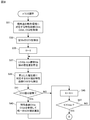
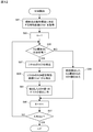
- FIG. 10 is a flowchart showing yet another portion of the operation of the system control circuit shown in FIG. 1. It is a flowchart which shows a part of other operation
- the assembled battery circuit 10 of this embodiment includes a system control circuit 16 that controls charging / discharging of the assembled battery 20 through the charging / discharging circuit 18.
- the charge / discharge circuit 18 charges the assembled battery 20 with the electric power supplied from the system power supply 12 or discharges the electric power of the assembled battery 20 to the load 14 under the control of the system control circuit 16.
- the assembled battery 20 is formed by connecting Kmax standard cells 20st and a single shift cell (specific cell) 20sh in series.
- the standard cell 20st and the shift cell 20sh are formed by laminating a positive electrode and a negative electrode with a separator interposed between them, housed in a laminate, filled with an electrolytic solution, and sealed.
- the constant Kmax is an integer equal to or greater than 2, for example, “7”.
- the standard cell 20st and the shift cell 20sh both have standard capacities, but the curves representing changes in the open circuit voltage (OCV) with respect to the SOC are different between the standard cell 20st and the shift cell 20sh (details will be described later).
- the standard cell 20st is configured in detail as shown in FIG. According to FIG. 2, one end of the switch SWst is connected to the positive electrode of the cell Est, and the other end of the switch SWst is connected to one end of the external short-circuit resistor Rst. The other end of the external short-circuit resistor Rst is connected to the negative electrode of the cell Est.
- the value of the current discharged from the cell Est when the switch SWst is turned on is defined by the terminal voltage value of the cell Est and the value of the external short-circuit resistance Rst.
- One of the capacity coefficients representing the capacity of each of the standard cell 20st and the shift cell 20sh is SOC.
- the SOC of the standard cell 20st is determined based on “the full charge capacity of the standard cell 20st before deterioration”.
- the current charge capacity of the standard cell 20st is defined, and the SOC of the shift cell 20sh is defined as "current charge capacity of the shift cell 20sh with reference to the full charge capacity of the shift cell 20sh before deterioration".
- the positive electrode and the negative electrode are made of olivine-type lithium iron phosphate (LFP) and graphite (Gr), respectively, and the AC ratio (the opposite charge capacity ratio between the positive electrode and the negative electrode) is “1”. .75 ".
- a region where the SOC gradient of the positive electrode is 2 [mV / SOC%] or less is 30% or more of the cell effective SOC, and a region where the SOC gradient of the negative electrode is 2.5 [mV / SOC%] is the cell effective SOC. 30% or more. Furthermore, the capacity is 4.5 Ah. That is, the material and design of the shift cell 20sh are the same as the material and design of the standard cell 20st.
- a curve CVst is a curve representing a change in the open circuit voltage of the standard cell 20st with respect to the SOC of the standard cell 20st assigned to the horizontal axis (reference axis), and the curve CVsh is assigned to the horizontal axis. It is a curve showing the change of the open circuit voltage of the shift cell 20sh with respect to the SOC of the shift cell 20sh. That is, both of the curves CVst and CVsh represent changes in the open circuit voltage of the target cell with respect to the SOC of the target cell.
- the open circuit voltage value of the standard cell 20st is distributed in the range of SOC from 0% to 100%, while the open circuit voltage value of the shift cell 20sh is distributed in the range of SOC from ⁇ 30% to 70%.
- the curve CVsh overlaps the curve obtained by shifting the curve CVst by 30 points (predetermined amount) to the negative side in the horizontal axis direction.
- the curve CVst is defined as “SOC / standard cell voltage characteristic curve”
- the curve CVsh is defined as “SOC / shift cell voltage characteristic curve”.
- the SOC / standard cell voltage characteristic curve CVst and the SOC / shift cell voltage characteristic curve CVsh may be referred to as a “standard curve” and a “shift curve”, respectively.
- each of the SOC / standard cell voltage characteristic curve CVst and the SOC / shift cell voltage characteristic curve CVsh has a potential plateau region (an SOC region in which voltage fluctuation is small).
- the SOC / standard cell voltage characteristic curve CVst and the SOC / shift cell voltage characteristic curve CVsh have the relationship as described above, the position of the potential plateau region is determined by the SOC / standard cell voltage characteristic curve CVst and the SOC / shift cell voltage characteristic curve CVsh. Differ between.
- the assembled battery 20 is provided with Kmax standard cells 20st and there are individual differences between the standard cells 20st, the relationship between the open circuit voltage of the standard cell 20st and the SOC of the standard cell 20st is as follows. Slightly different for each.
- the relationship between the open circuit voltage of the standard cell 20st and the SOC of the standard cell 20st varies depending on the operating environment of the battery pack circuit 10 (separate charge / discharge, temperature of the battery pack 20), and the open circuit voltage of the shift cell 20sh and the shift cell 20sh.
- the relationship with the SOC also varies depending on the operating environment of the battery pack circuit 10.
- the number of SOC / standard cell voltage characteristic curves CVst equal to Kmax ⁇ the number of operating environments and the number of SOC / shift cell voltage characteristic curves CVsh equal to the number of operating environments are stored in the memory 16m in advance.
- the potential difference between the standard cell 20st and the shift cell 20sh. Reflects the difference between the SOC / standard cell voltage characteristic curve CVst and the SOC / shift cell voltage characteristic curve CVsh, and a partial region where the SOC shows a value in the vicinity of 60%. Except for the fluctuations.
- the curve CVdf has a plurality of extreme values, and the plateau region appears only in a partial region. This means that a slight error occurs in the vicinity of 60% when the SOC value is detected with reference to the curve CVdf.
- a curve CVdf is defined as an “SOC / potential difference characteristic curve”.
- the number of SOC / standard cell voltage characteristic curves CVst is equal to Kmax ⁇ the number of operating environments
- the number of SOC / shift cell voltage characteristic curves CVsh is equal to the number of operating environments. Accordingly, the number of SOC / potential difference characteristic curves CVdf equal to Kmax ⁇ the number of operating environments is stored in the memory 16m in advance.
- the standard cell 20st and the shift cell 20sh adopting a common material and design cause aging deterioration in the same manner.
- the SOC / standard cell voltage characteristic curve CVst draws a locus shown in FIG.
- the shift cell 20sh also draws a similar locus with deterioration. That is, the SOC / standard cell voltage characteristic curve CVst and the SOC / shift cell voltage characteristic curve CVsh are compressed at a predetermined compression rate in a region other than the low SOC region.
- the SOC / standard cell voltage characteristic curve CVst shown in FIG. 5 shows a locus when the output characteristics deteriorate in the order of 100%, 97%, 90%, 83%, 73%, 64%, and 58%.
- the system control circuit (processor) 26 repeatedly detects the SOC value of the standard cell 20st according to the flow charts shown in FIGS. 6 to 7, and adjusts the charge balance of the standard cell 20st and the shift cell 20sh according to the flow charts shown in FIGS. Adjust repeatedly.
- a control program corresponding to these flowcharts is also stored in the memory 16m.
- step S1 SOC / standard cell voltage characteristic curve CVst, SOC / shift cell voltage characteristic curve CVsh, and SOC / potential difference characteristic curve CVdf corresponding to the current operating environment are obtained from memory 16m.
- the For the SOC / potential difference characteristic curve CVdf a curve representing a change in potential difference between the shift cell 20sh and the reference standard cell 20st with respect to the SOC of the reference standard cell 20st is acquired.
- step S3 the current open circuit voltage of the shift cell 20sh is detected.
- step S5 it is determined whether or not the SOC value corresponding to the detected open circuit voltage belongs to the potential plateau region on the SOC / shift cell voltage characteristic curve CVsh acquired in step S1. If the determination result is NO, the process proceeds to step S7, and if the determination result is YES, the process proceeds to step S11.
- step S7 the open circuit voltage detected in step S3 is collated with the SOC / shift cell voltage characteristic curve CVsh acquired in step S1, and the current SOC value of the shift cell 20sh is detected.
- step S9 a value obtained by adding 30 points to the detected SOC value is output from the monitor (not shown) as the current SOC value of the standard cell 20st, and then the current SOC detection processing is terminated.
- step S11 the current open circuit voltage of the reference standard cell 20st is detected.
- step S13 it is determined whether or not the SOC value corresponding to the detected open circuit voltage belongs to the potential plateau region on the SOC / standard cell voltage characteristic curve CVst acquired in step S1. If the determination result is NO, the process proceeds to step S15, and if the determination result is YES, the process proceeds to step S19.
- step S15 the open circuit voltage detected in step S11 is collated with the SOC / standard cell voltage characteristic curve CVst acquired in step S1, and the current SOC value of the reference standard cell 20st is detected.
- step S17 the detected SOC value is output from the monitor as the current SOC value of the standard cell 20st, and then the current SOC detection process is terminated.
- step S19 shown in FIG. 7 the current potential difference between the shift cell 20sh and the reference standard cell 20st is calculated.
- step S21 one or two or more SOC values corresponding to the calculated potential difference are obtained from the SOC ⁇ Detection is performed on the potential difference characteristic curve CVdf.
- step S21 If the SOC / potential difference characteristic curve CVdf acquired in step S1 draws the curve shown in FIG. 4 and the potential difference calculated in step S19 is 0.05 V, two SOC values are detected in step S21.
- step S23 it is determined whether or not the number of detected SOC values is 2 or more. If the determination result is NO, the process proceeds to step S27 as it is. If the determination result is YES, the following processing is performed in step S25. After execution, the process proceeds to step S27.
- step S25 with reference to at least one of the SOC / standard cell voltage characteristic curve CVst and the SOC / shift cell voltage characteristic curve CVsh acquired in step S1, a unique SOC value corresponding to the open circuit voltage of the reference standard cell 20st is obtained.
- Select As can be seen from FIGS. 3 and 4, when the open circuit voltage of the reference standard cell 20st is 3.25V and the open circuit voltage of the shift cell 20sh is 3.3V, “35%” is selected as the only SOC value in step S25. Is done.
- step S27 the only SOC value thus detected or selected is output from the monitor, and then the current SOC detection process is terminated.
- step S31 Kmax SOC / standard cell voltage characteristic curves CVst corresponding to the current operating environment, a single SOC / shift cell voltage characteristic curve CVsh, and Kmax corresponding to the current operating environment.
- the SOC / potential difference characteristic curve CVdf is obtained from the memory 16m.
- step S33 the current open circuit voltage of each of the Kmax standard cells 20st and the single shift cell 20sh is detected.
- step S35 the variable K is set to “1”, and in step S37, the current potential difference between the shift cell 20sh and the Kth standard cell 20st is calculated.
- step S39 one or more SOC values corresponding to the calculated potential difference are detected on the Kth SOC / potential difference characteristic curve CVdf acquired in step S31.
- step S41 it is determined whether or not the number of detected SOC values is 2 or more. If the determination result is NO, the process proceeds to step S45 as it is. If the determination result is YES, the following processing is performed in step S43. After execution, the process proceeds to step S45.
- step S43 with reference to at least one of the Kth SOC / standard cell voltage characteristic curve CVst and the SOC / shift cell voltage characteristic curve CVsh acquired in step S31, the circuit corresponds to the open circuit voltage of the Kth standard cell 20st. Select a unique SOC value.
- step S45 the variable K is incremented, and in step S47, it is determined whether or not the variable K exceeds a constant Kmax. If a determination result is NO, it will return to Step S37, and if a determination result is YES, it will progress to Step S49.
- step S49 the standard cell 20st having the minimum SOC value is detected from the Kmax standard cells 20st.
- step S51 the identification number of the detected standard cell 20st is set to the variable L.
- step S53 the variable K is set to “1”.
- step S55 it is determined whether or not the variable K is equal to the variable L. If the determination result is YES, the process proceeds directly to step S61, while if the determination result is NO, the following processing is executed in steps S57 to S59, and then the process proceeds to step S61.
- step S59 for the Kth standard cell 20st, the switch SWst is turned on, the balance current value is calculated from the value of the external short-circuit resistance Rst and the characteristics of the cell Est, and the calculated balance current value
- the discharge time of the Kth standard cell 20st is calculated. The calculated discharge time is a time until the SOC value of the Kth standard cell 20st falls below the minimum SOC value.
- step S61 the variable K is incremented, and in step S63, it is determined whether or not the variable K exceeds a constant Kmax. If a determination result is NO, it will return to Step S55, and if a determination result is YES, it will progress to Step S65.
- step S65 the switch SWst is turned on for the standard cells 20st other than the Lth standard cell 20st. As a result, discharge is started.
- step S67 the variable K is set to “1”.
- step S69 it is determined whether or not the variable K is equal to the variable L.
- step S75 it is determined whether or not the variable K has reached a constant Kmax.
- step S79 it is determined whether or not all the discharge operations of the Kmax standard cells 20st have been completed. If the decision result in the step S75 is NO, the variable K is incremented in a step S77, and thereafter, the process returns to the step S69.
- step S75 If the determination result of step S75 is YES, if the determination result of step S79 is NO, the process returns to step S67. If both the determination result in step S75 and the determination result in step S79 are YES, the current balance adjustment process is terminated.
- the open circuit voltage of the standard cell 20st changes along the SOC / standard cell voltage characteristic curve CVst
- the open circuit voltage of the shift cell 20sh changes along the SOC / shift cell voltage characteristic curve CVsh.
- the SOC / shift cell voltage characteristic curve CVsh overlaps a curve obtained by shifting the SOC / standard cell voltage characteristic curve CVst by a predetermined amount in the horizontal axis direction.
- the system control circuit 16 acquires Kmax SOC / potential difference characteristic curves CVdf corresponding to the Mmax standard cells 20st from the memory 16m (S31). ), A potential difference between each of the Kth (K: 1 to Kmax) standard cells 20st and the shift cell 20sh is detected (S37), and the detected potential difference is collated with the Kth SOC / potential difference characteristic curve CVdf. Then, the SOC value of the Kth standard cell 20st is detected (S39).
- the SOC / shift cell voltage characteristic curve CVsh overlaps the curve obtained by shifting the SOC / standard cell voltage characteristic curve CVst by a predetermined amount in the horizontal axis direction. Therefore, even in the capacitance coefficient region (potential plateau region) where the voltage variation of the standard cell 20st is small, the potential difference can vary greatly on the SOC / potential difference characteristic curve CVdf.
- the SOC value of the standard cell 20st can be detected easily and with high accuracy even in the potential plateau region, and the standard cell based on the detected SOC value.
- the charging balance for 20 st can be adjusted.
- the material and design of the shift cell 20sh are the same as the material and design of the standard cell 20st, the same rate characteristic and life characteristic can be obtained. As a result, it is possible to suppress the work load required to rebalance the shift cell 20sh and the standard cell 20st.
- FIG. 11 shows changes in power when a constant current is output from the reference assembled battery in a state where a load is applied. According to FIG. 11, the former power changes along the curve CWsh, while the latter power changes along the curve CWst.
- the increase in the total voltage of the assembled battery 20 in the low SOC region means that the total voltage of the assembled battery 20 is flattened in a region having a large gradient other than the plateau region. Accordingly, the assembled battery 20 is an assembled battery having a high potential flatness and a wide SOC detection range.
- the number of shift cells 20sh provided in the assembled battery 20 is one, but two or more shift cells 20sh may be provided in the assembled battery 20.
- the shift amount is set to 30%, but the shift amount may be appropriately changed within a range of 10% or more and less than 50%.
- the assembled battery circuit 10 is provided with a single assembled battery 20, but a plurality of assembled batteries 20 are connected in parallel or in series, and the processing shown in FIGS. It may be executed for each battery 20.
- the SOC value of the standard cell 20st is detected, but the SOH value of the standard cell 20st may be detected instead.
- the SOH of the standard cell 20st can be defined as “the current full charge capacity of the standard cell 20st based on the full charge capacity of the standard cell 20st before deterioration”, and the SOH of the shift cell 20sh is “the shift cell before deterioration”. It can be defined as “the full charge capacity of the current shift cell 20 sh with reference to the full charge capacity of 20 sh”.
- step S81 SOH / shift cell voltage characteristic curve CVsh ′ corresponding to the current operating environment is acquired from memory 16m.
- step S83 the variable K is set to “1”, and in step S85, it is determined whether or not the Kth standard cell 20st is fully charged.
- step S87 the process proceeds to step S87, and the current open circuit voltage of the shift cell 20sh is detected.
- step S89 the open circuit voltage detected in step S87 is collated with the SOH / shift cell voltage characteristic curve CVsh ′ acquired in step S81 to detect the current SOH value of the shift cell 20sh.
- step S91 a value obtained by adding 30 points to the detected SOH value is output from the monitor as the current SOH value of the Kth standard cell 20st. When the output is completed, the process proceeds to step S95.
- step S85 If the decision result in the step S85 is NO, the process proceeds to a step S93, and the SOH value obtained by the previous step S91 for the Kth standard cell is outputted from the monitor. When the output is completed, the process proceeds to step S95.
- step S95 the variable K is incremented, and in step S97, it is determined whether or not the variable K exceeds a constant Kmax. If the determination result is NO, the process returns to step S85, while if the determination result is YES, the current SOH detection process is terminated.
Landscapes
- Engineering & Computer Science (AREA)
- Power Engineering (AREA)
- Manufacturing & Machinery (AREA)
- Chemical & Material Sciences (AREA)
- Chemical Kinetics & Catalysis (AREA)
- Electrochemistry (AREA)
- General Chemical & Material Sciences (AREA)
- Physics & Mathematics (AREA)
- General Physics & Mathematics (AREA)
- Secondary Cells (AREA)
- Charge And Discharge Circuits For Batteries Or The Like (AREA)
- Tests Of Electric Status Of Batteries (AREA)
Abstract
標準セル20stの開路電圧はSOC・標準セル電圧特性曲線に沿って変化する一方、シフトセル20shの開路電圧はSOC・シフトセル電圧特性曲線に沿って変化する。SOC・シフトセル電圧特性曲線は、SOC・標準セル電圧特性曲線を横軸方向に既定量シフトさせた曲線と重なる。システム制御回路16は、標準セル20st・シフトセル20sh間の電位差のSOCに対する変化を表すSOC・電位差特性曲線をメモリ16mから取得し、標準セル20st・シフトセル20sh間の現時点の電位差を算出する。システム制御回路16はまた、算出された現時点の電位差をSOC・電位差特性曲線と照合して、標準セル20stの現時点のSOC値を検出する。
Description
この発明は、組電池回路に関し、特に標準容量を有する複数のセルによって形成された組電池の充放電を制御する、組電池回路に関する。この発明はまた、組電池を構成するセルの容量係数を検出する、容量係数検出方法、および容量係数検出プログラムに関する。
電池のSOC(State Of Charge:電池の容量係数であり、具体的には充電深度)を検知する場合、通常は、電圧-SOCテーブルが準備され、電池を測定して得られた電圧が電圧-SOCテーブルと照合される。
しかし、正極LFP-負極Gr系電池などの電位プラトー領域の大きい電池については、電位プラトー領域でSOCを検知するのは容易ではない。つまり、実際には、電位プラトー領域以外の領域で検知したSOCとその後の電流量の積算値とに基づいて、電位プラトー領域におけるSOCを検知することになる。このような方法では、SOCの検知精度に限界がある。
SOH(State Of Health:電池の容量係数であり、具体的には劣化度)についても、一般的な電池では、劣化に伴ってΔ容量/ΔV(=電位の変動幅に対する容量の変動幅の割合)が小さくなることを検知して、電池の劣化状態を判定することができる。しかし、正極LFP-負極Gr系電池では、劣化に伴って電位プラトー領域のみが縮退するのみであり、Δ容量/ΔVが変化することはないため、電池の劣化状態を判定することは不可能である。つまり、電位プラトー領域の大きい電池では電流値を積算してSOHを定量化するため、SOHの検知精度に限界がある。
これを踏まえて、特許文献1では、初期電池容量が互いに異なる充電深度検知用リチウムイオン二次電池(検知用セル)と非充電深度検知用リチウムイオン二次電池(通常セル)とを直列接続して、組電池が構成される。これによって、大電流による充放電中でも、複雑な判定回路を必要とせず、充電深度を精度良く評価できる。
特許文献1のような組電池を長期にわたって安定的に利用するためには、検知用セルの劣化状態に基づく電圧-SOCテーブルと、通常セルの劣化状態に基づく電圧-SOCテーブルとを個別に準備し、各セルの劣化状態を監視してSOCをリセットする(セル間でSOCを揃える)必要がある。
ただし、性能や劣化特性の異なる2種類のセルを対象とする監視・リセットは、煩雑さを増大させる。また、低抵抗で大電流を流すパワータイプの電池においては、材料系の異なる2種類のセルを設計すること自体が困難である。さらに、従来の巻回缶タイプの電池においては、缶に自由度がなく、容量アップなどの異種設計を行うことは容易ではない。したがって、特許文献1のような組電池は、実用性に欠ける。
それゆえに、この発明の主たる目的は、電位プラトー領域においても簡単かつ高精度で容量係数を検知することができる、組電池回路を提供することである。
この発明に係る組電池回路(10:実施例で相当する参照符号。以下同じ)は、基準軸に割り当てられた容量係数に対する電圧の変化を表す容量係数・電圧特性曲線が標準曲線(CVst)を描く標準セル(20st)と、容量係数・電圧特性曲線が標準曲線を基準軸の延在方向に既定量シフトさせたシフト曲線(CVsh)を描く特定セル(20sh)とによって構成された組電池(20)の充放電を制御する組電池回路(10)であって、標準セルおよび特定セル間の電位差の容量係数に対する変化を表す容量係数・電位差特性曲線(CVdf)をメモリ(16m)から取得する容量係数・電位差特性曲線取得手段(S1, S31)、標準セルおよび特定セル間の電位差を検出する電位差検出手段(S19, S37)、および電位差検出手段によって検出された電位差を容量係数・電位差特性曲線取得手段によって取得された容量係数・電位差特性曲線と照合して標準セルの現時点の容量係数値を検出する容量係数値検出手段(S21, S39)を備える。
標準セルの容量係数・電圧特性曲線は標準曲線を描く一方、特定セルの容量係数・電圧特性曲線は標準曲線を基準軸の延在方向に既定量シフトさせたシフト曲線を描く。したがって、標準セルの電圧の変動が少ない容量係数領域(電位プラトー領域)においても、容量係数・電位差特性曲線上では電位差が大きく変動し得る。このような容量係数・電位差特性曲線を参照することで、電位プラトー領域においても簡単かつ高精度で標準セルの容量係数を検出することができる。
好ましくは、標準曲線(CVst)および/またはシフト曲線(CVtw)をメモリから取得する容量係数・電圧特性曲線取得手段(S1, S31)、および容量係数値検出手段によって検出された容量係数値の数が2以上のとき容量係数・電圧特性曲線取得手段によって取得された曲線に基づいて唯一の容量係数値を選定する容量係数値選定手段(S23, S25, S41, S43)がさらに備えられる。
標準曲線および/またはシフト曲線を参照することで、標準セルの容量係数値が誤検出される懸念を軽減することができる。
好ましくは、容量係数値検出手段によって検出された容量係数値を出力する容量係数値出力手段(S27)がさらに備えられる。これによって、標準セルの容量係数値を容易に確認することができる。
好ましくは、標準セルの数は複数であり、電位差検出手段および容量係数値検出手段の各々は標準セル毎に検出処理を実行し、容量係数値検出手段によって検出された容量係数値に基づいて標準セル間の充電バランスを調整するバランス調整手段(S49~S63)がさらに備えられる。
容量係数・電位差特性曲線を参照することで、電位プラトー領域においても標準セル間の充電バランスを調整することができる。
好ましくは、容量係数は劣化前の対象セルの満充電容量を基準とする現時点の対象セルの容量を表す係数である。
この発明に係る容量係数検出方法は、基準軸に割り当てられた容量係数に対する電圧の変化を表す容量係数・電圧特性曲線が標準曲線(CVst)を描く標準セル(20st)と、容量係数・電圧特性曲線が標準曲線を基準軸の延在方向に既定量シフトさせたシフト曲線(CVsh)を描く特定セル(20sh)とによって構成された組電池(20)の充放電を制御する組電池回路(10)によって実行される容量係数検出方法であって、標準セルおよび特定セル間の電位差の容量係数に対する変化を表す容量係数・電位差特性曲線(CVdf)をメモリ(16m)から取得する容量係数・電位差特性曲線取得ステップ(S1, S31)、標準セルおよび特定セル間の電位差を検出する電位差検出ステップ(S19, S37)、および電位差検出ステップによって検出された電位差を容量係数・電位差特性曲線取得ステップによって取得された容量係数・電位差特性曲線と照合して標準セルの現時点の容量係数値を検出する容量係数値検出ステップ(S21, S39)を備える。
この発明に係る容量係数検出プログラムは、基準軸に割り当てられた容量係数に対する電圧の変化を表す容量係数・電圧特性曲線が標準曲線(CVst)を描く標準セル(20st)と、容量係数・電圧特性曲線が標準曲線を基準軸の延在方向に既定量シフトさせたシフト曲線(CVsh)を描く特定セル(20sh)とによって構成された組電池(20)の充放電を制御する組電池回路(10)のプロセッサ(16)に、標準セルおよび特定セル間の電位差の容量係数に対する変化を表す容量係数・電位差特性曲線(CVdf)をメモリ(16m)から取得する容量係数・電位差特性曲線取得ステップ(S1, S31)、標準セルおよび特定セル間の電位差を検出する電位差検出ステップ(S19, S37)、および電位差検出ステップによって検出された電位差を容量係数・電位差特性曲線取得ステップによって取得された容量係数・電位差特性曲線と照合して標準セルの現時点の容量係数値を検出する容量係数値検出ステップ(S21, S39)を実行させるための、容量係数検出プログラムである。
この発明によれば、電位プラトー領域においても簡単かつ高精度で容量係数を検知することができる。
この発明の上述の目的,その他の目的,特徴および利点は、図面を参照して行う以下の実施例の詳細な説明から一層明らかとなろう。
図1を参照して、この実施例の組電池回路10は、充放電回路18を通して組電池20の充放電を制御するシステム制御回路16を含む。充放電回路18は、システム制御回路16の制御の下で、系統電源12から供給された電力を組電池20に充電し、或いは組電池20の電力を負荷14に対して放電する。
組電池20は、Kmax個の標準セル20stと単一のシフトセル(特定セル)20shとを直列接続してなる。標準セル20stとシフトセル20shは正極と負極とをセパレータを介して積層し、ラミネートに収納し、電解液を充填して封止してなる。ここで、定数Kmaxは2以上の整数であり、たとえば“7”である。また、標準セル20stおよびシフトセル20shはいずれも標準容量を有するが、SOCに対する開路電圧(OCV)の変化を表す曲線は標準セル20stおよびシフトセル20shの間で相違する(詳細は後述)。
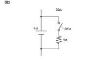
標準セル20stは、詳しくは図2に示すように構成される。図2によれば、スイッチSWstの一方端はセルEstの正極に接続され、スイッチSWstの他方端は外部短絡抵抗Rstの一方端に接続される。また、外部短絡抵抗Rstの他方端はセルEstの負極に接続される。スイッチSWstをオンしたときにセルEstから放電される電流の値は、セルEstの端子電圧値と外部短絡抵抗Rstの値とによって規定される。
標準セル20stおよびシフトセル20shの各々の容量を表す容量係数の1つとしてSOCがあるが、この実施例では特に、標準セル20stのSOCを“劣化前の標準セル20stの満充電容量を基準とする現時点の標準セル20stの充電容量”と定義し、シフトセル20shのSOCを“劣化前のシフトセル20shの満充電容量を基準とする現時点のシフトセル20shの充電容量”と定義する。
標準セル20stおよびシフトセル20shのいずれについても、正極および負極はそれぞれ、オリビン型リン酸鉄リチウム(LFP)およびグラファイト(Gr)を材料とし、AC比(正極と負極の対向充電容量比)は“1.75”である。
また、正極のSOC勾配が2[mV/SOC%]以下の領域はセル実効SOCの30%以上であり、かつ、負極のSOC勾配が2.5[mV/SOC%]の領域はセル実効SOCの30%以上である。さらに、容量は4.5Ahである。つまり、シフトセル20shの材料および設計は、標準セル20stの材料および設計と同一である。
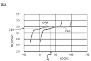
図3を参照して、曲線CVstは、横軸(基準軸)に割り当てられた標準セル20stのSOCに対する標準セル20stの開路電圧の変化を表す曲線であり、曲線CVshは、横軸に割り当てられたシフトセル20shのSOCに対するシフトセル20shの開路電圧の変化を表す曲線である。つまり、曲線CVstおよびCVshはいずれも、対象セルのSOCに対する対象セルの開路電圧の変化を表す。
図3によれば、標準セル20stの開路電圧値はSOCが0%から100%までの範囲に分布する一方、シフトセル20shの開路電圧値はSOCが-30%から70%までの範囲に分布する。ただし、シフトセル20shの材料および設計は標準セル20stの材料および設計と同一であるため、曲線CVshは、曲線CVstを横軸方向の負側に30ポイント(既定量)シフトさせた曲線と重なる。
以下では、曲線CVstを“SOC・標準セル電圧特性曲線”と定義し、曲線CVshを“SOC・シフトセル電圧特性曲線”と定義する。なお、SOC・標準セル電圧特性曲線CVstおよびSOC・シフトセル電圧特性曲線CVshはそれぞれ、“標準曲線”および“シフト曲線”呼んでもよい。
図3から分かるように、SOC・標準セル電圧特性曲線CVstおよびSOC・シフトセル電圧特性曲線CVshの各々は、電位プラトー領域(電圧の変動が少ないSOC領域)を有する。しかし、SOC・標準セル電圧特性曲線CVstおよびSOC・シフトセル電圧特性曲線CVshが上述のような関係を有するため、電位プラトー領域の位置はSOC・標準セル電圧特性曲線CVstおよびSOC・シフトセル電圧特性曲線CVshの間で相違する。
なお、組電池20にはKmax個の標準セル20stが設けられ、かつ標準セル20st間には個体差があるため、標準セル20stの開路電圧と標準セル20stのSOCとの関係は、標準セル20st毎に僅かに異なる。
また、標準セル20stの開路電圧と標準セル20stのSOCとの関係は組電池回路10の動作環境(充電/放電の別,組電池20の温度)によって変動し、シフトセル20shの開路電圧とシフトセル20shのSOCとの関係もまた組電池回路10の動作環境によって変動する。
これを踏まえて、メモリ16mには、Kmax×動作環境数に等しい数のSOC・標準セル電圧特性曲線CVstと、動作環境数に等しい数のSOC・シフトセル電圧特性曲線CVshとが予め記憶される。
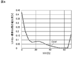
図4を参照して、曲線CVdfは、0%以上70%未満のSOC領域における、標準セル20stのSOCに対する標準セル20st・シフトセル20sh間の開路電圧の差(=電位差)の変化を表す曲線である。標準セル20st・シフトセル20sh・間の電位差は、SOC・標準セル電圧特性曲線CVstおよびSOC・シフトセル電圧特性曲線CVshの相違を反映し、SOCが60%の近傍の値を示す極一部の領域を除いて激しく変動する。
つまり、曲線CVdfは複数の極値を有し、プラトー領域は極一部の領域に現れるに過ぎない。これは、曲線CVdfを参照してSOC値を検出する場合に、60%の近傍において僅かな誤差が生じるに過ぎないことを意味する。以下では、このような曲線CVdfを“SOC・電位差特性曲線”と定義する。
上述したように、SOC・標準セル電圧特性曲線CVstの数はKmax×動作環境数に等しく、SOC・シフトセル電圧特性曲線CVshの数は動作環境数に等しい。したがって、メモリ16mには、Kmax×動作環境数に等しい数のSOC・電位差特性曲線CVdfが予め記憶される。
ただし、共通の材料および設計を採用する標準セル20stおよびシフトセル20shは、互いに同じ要領で経年劣化を起こす。たとえば標準セル20stの出力特性が58%まで徐々に劣化したとき、SOC・標準セル電圧特性曲線CVstは図5に示す軌跡を描く。シフトセル20shもまた、劣化に伴って同様の軌跡を描く。つまり、SOC・標準セル電圧特性曲線CVstおよびSOC・シフトセル電圧特性曲線CVshは、低SOC領域以外の領域において、所定の圧縮率で圧縮される。
なお、図5に示すSOC・標準セル電圧特性曲線CVstは、出力特性が100%,97%,90%,83%,73%,64%,58%の順で劣化したときの軌跡を示す。
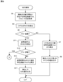
システム制御回路(プロセッサ)26は、図6~図7に示すフロー図に従って標準セル20stのSOC値を繰り返し検知し、図8~図10に示すフロー図に従って標準セル20stおよびシフトセル20shの充電バランスを繰り返し調整する。なお、これらのフロー図に対応する制御プログラムもまた、メモリ16mに記憶される。
図6を参照して、ステップS1では、現時点の動作環境に対応するSOC・標準セル電圧特性曲線CVst,SOC・シフトセル電圧特性曲線CVsh,SOC・電位差特性曲線CVdfをメモリ16mから取得する。
SOC・標準セル電圧特性曲線CVstについては、参照標準セル(=Kmax個の標準セル20stのうち予め指定された標準セル20st)のSOCに対する参照標準セル20stの開路電圧の変化を表す曲線が取得される。また、SOC・電位差特性曲線CVdfについては、参照標準セル20stのSOCに対するシフトセル20sh・参照標準セル20st間の電位差の変化を表す曲線が取得される。
ステップS3では、シフトセル20shの現時点の開路電圧を検出する。ステップS5では、検出された開路電圧に対応するSOC値がステップS1で取得したSOC・シフトセル電圧特性曲線CVsh上の電位プラトー領域に属するか否かを判別する。判別結果がNOであればステップS7に進み、判別結果がYESであればステップS11に進む。
ステップS7では、ステップS3で検出された開路電圧をステップS1で取得したSOC・シフトセル電圧特性曲線CVshと照合して、シフトセル20shの現時点のSOC値を検出する。ステップS9では、検出されたSOC値に30ポイントを加算した値を標準セル20stの現時点のSOC値としてモニタ(図示せず)から出力し、その後に今回のSOC検知処理を終了する。
ステップS11では、参照標準セル20stの現時点の開路電圧を検出する。ステップS13では、検出された開路電圧に対応するSOC値がステップS1で取得したSOC・標準セル電圧特性曲線CVst上の電位プラトー領域に属するか否かを判別する。判別結果がNOであればステップS15に進み、判別結果がYESであればステップS19に進む。
ステップS15では、ステップS11で検出された開路電圧をステップS1で取得したSOC・標準セル電圧特性曲線CVstと照合して、参照標準セル20stの現時点のSOC値を検出する。ステップS17では、検出されたSOC値を標準セル20stの現時点のSOC値としてモニタから出力し、その後に今回のSOC検知処理を終了する。
図7に示すステップS19では、シフトセル20shと参照標準セル20stとの間の現時点の電位差を算出し、ステップS21では算出した電位差に対応する1または2以上のSOC値をステップS1で取得したSOC・電位差特性曲線CVdf上で検出する。
ステップS1で取得したSOC・電位差特性曲線CVdfが図4に示す曲線を描き、ステップS19で算出した電位差が0.05Vであれば、ステップS21では2つのSOC値が検出される。
ステップS23では検出されたSOC値の数が2以上であるか否かを判別し、判別結果がNOであればそのままステップS27に進む一方、判別結果がYESであればステップS25で以下の処理を実行してからステップS27に進む。
つまり、ステップS25では、ステップS1で取得したSOC・標準セル電圧特性曲線CVstおよびSOC・シフトセル電圧特性曲線CVshの少なくとも一方を参照して、参照標準セル20stの開路電圧に対応する唯一のSOC値を選定する。図3および図4から分かるように、参照標準セル20stの開路電圧が3.25Vでかつシフトセル20shの開路電圧が3.3Vである場合、ステップS25では“35%”が唯一のSOC値として選定される。
ステップS27では、こうして検出ないし選定された唯一のSOC値をモニタから出力し、その後に今回のSOC検知処理を終了する。
図8を参照して、ステップS31では、現時点の動作環境に対応するKmax個のSOC・標準セル電圧特性曲線CVst,単一のSOC・シフトセル電圧特性曲線CVsh,現時点の動作環境に対応するKmax個のSOC・電位差特性曲線CVdfをメモリ16mから取得する。
ステップS33では、Kmax個の標準セル20stおよび単一のシフトセル20shの各々の現時点の開路電圧を検出する。ステップS35では変数Kを“1”に設定し、ステップS37ではシフトセル20shとK番目の標準セル20stとの間の現時点の電位差を算出する。ステップS39では、算出した電位差に対応する1または2以上のSOC値を、ステップS31で取得したK番目のSOC・電位差特性曲線CVdf上で検出する。
ステップS41では検出されたSOC値の数が2以上であるか否かを判別し、判別結果がNOであればそのままステップS45に進む一方、判別結果がYESであればステップS43で以下の処理を実行してからステップS45に進む。
つまり、ステップS43では、ステップS31で取得したK番目のSOC・標準セル電圧特性曲線CVstおよびSOC・シフトセル電圧特性曲線CVshの少なくとも一方を参照して、K番目の標準セル20stの開路電圧に対応する唯一のSOC値を選定する。
ステップS45では変数Kをインクリメントし、ステップS47では変数Kが定数Kmaxを上回るか否かを判別する。判別結果がNOであればステップS37に戻り、判別結果がYESであればステップS49に進む。
ステップS49では、SOC値が最小値を示す標準セル20stをKmax個の標準セル20stの中から検出する。ステップS51では、検出した標準セル20stの識別番号を変数Lに設定する。ステップS53では変数Kを“1”に設定し、ステップS55では変数Kが変数Lに等しいか否かを判別する。判別結果がYESであればそのままステップS61に進む一方、判別結果がNOであればステップS57~S59で以下の処理を実行してからステップS61に進む。
ステップS57では、K番目の標準セル20stのSOC値と最小SOC値(=L番目の標準セル20stのSOC値)との差分を算出する。ステップS59では、K番目の標準セル20stを対象として、スイッチSWstをオン状態にした上で、外部短絡抵抗Rstの値とセルEstの特性からバランス電流値を算出し、算出されたバランス電流値とステップS57で算出された差分とに基づいて、K番目の標準セル20stの放電時間を算出する。算出される放電時間は、K番目の標準セル20stのSOC値が最小SOC値を下回るまでの時間である。
ステップS61では変数Kをインクリメントし、ステップS63では変数Kが定数Kmaxを上回るか否かを判別する。判別結果がNOであればステップS55に戻り、判別結果がYESであればステップS65に進む。ステップS65では、L番目の標準セル20st以外の標準セル20stについて、スイッチSWstをオンする。これによって、放電が開始される。
ステップS67では変数Kを“1”に設定し、ステップS69では変数Kが変数Lに等しいか否かを判別し、ステップS71ではK番目の標準セル20stについて設定された放電時間が経過したか否かを判別する。ステップS69の判別結果がYESであるか或いはステップS71の判別結果がNOであればそのままステップS75に進み、ステップS69の判別結果がNOでかつステップS71の判別結果がYESであればステップS73でK番目の標準セル20stの放電動作を終了(=K番目の標準セル20stに設けられたスイッチSWstをオフ)してからステップS75に進む。
ステップS75では変数Kが定数Kmaxに達したか否かを判別し、ステップS79ではKmax個の標準セル20stの全ての放電動作が終了したか否かを判別する。ステップS75の判別結果がNOであれば、ステップS77で変数Kをインクリメントし、その後にステップS69に戻る。
ステップS75の判別結果がYESである一方、ステップS79の判別結果がNOであれば、ステップS67に戻る。ステップS75の判別結果およびステップS79の判別結果のいずれもがYESであれば、今回のバランス調整処理を終了する。
以上の説明から分かるように、標準セル20stの開路電圧はSOC・標準セル電圧特性曲線CVstに沿って変化する一方、シフトセル20shの開路電圧はSOC・シフトセル電圧特性曲線CVshに沿って変化する。ここで、SOC・シフトセル電圧特性曲線CVshは、SOC・標準セル電圧特性曲線CVstを横軸方向に既定量シフトさせた曲線と重なる。
参照標準セル20st(=Kmax個の標準セル20stの中から予め指定された標準セル20st)のSOCを検出する際、システム制御回路16は、参照標準セル20st・シフトセル20sh間の電位差のSOCに対する変化を表すSOC・電位差特性曲線CVdfをメモリ16mから取得し(S1)、参照標準セル20st・シフトセル20sh間の現時点の電位差を算出する(S19)。システム制御回路16はまた、算出された現時点の電位差をSOC・電位差特性曲線CVdfと照合して、参照標準セル20stの現時点のSOC値を検出する(S21)。
システム制御回路16はまた、Kmax個の標準セル20stの間の充電バランスを調整する際、Mmax個の標準セル20stにそれぞれ対応するKmax個のSOC・電位差特性曲線CVdfをメモリ16mから取得し(S31)、K番目(K:1~Kmax)の標準セル20stの各々とシフトセル20shとの間の電位差を検出し(S37)、そして検出された電位差をK番目のSOC・電位差特性曲線CVdfと照合してK番目の標準セル20stのSOC値を検出する(S39)。
SOC・シフトセル電圧特性曲線CVshは、SOC・標準セル電圧特性曲線CVstを横軸方向に既定量シフトさせた曲線と重なる。したがって、標準セル20stの電圧の変動が少ない容量係数領域(電位プラトー領域)においても、SOC・電位差特性曲線CVdf上では電位差が大きく変動し得る。このようなSOC・電位差特性曲線CVdfを参照することで、電位プラトー領域においても簡単かつ高精度で標準セル20stのSOC値を検出することができ、さらには検出されたSOC値に基づいて標準セル20st間の充電バランスを調整することができる。
また、シフトセル20shの材料および設計は、標準セル20stの材料および設計と同一であるため、同一のレート特性および寿命特性が得られる。これによって、シフトセル20shと標準セル20stとのリバランスに掛かる作業負担を抑制することができる。
参考までに、この実施例の組電池20に47A負荷を掛けた状態で組電池20から定電流を出力させたときの電力の変化と、8つの標準セル20stによって構成された参照組電池に47A負荷を掛けた状態で参照組電池から定電流を出力させたときの電力の変化とを、図11に示す。図11によれば、前者の電力は曲線CWshに沿って変化する一方、後者の電力は曲線CWstに沿って変化する。
SOC・シフトセル電圧特性曲線CVshは図3に示すように変化するため、組電池20の総電圧は低SOC領域において上昇し、これによって組電池20の出力電力特性が向上する。
また、低SOC領域における組電池20の総電圧の上昇は、組電池20の総電圧がプラトー領域以外の勾配の大きい領域において平坦化されることを意味する。これより、組電池20は、電位平坦性が高くかつSOC検知範囲が広い組電池となる。
なお、この実施例では、組電池20に設けられたシフトセル20shの数は1つであるが、2以上のシフトセル20shを組電池20に設けるようにしてもよい。また、この実施例では、シフト量を30%としているが、シフト量は10%以上50%未満の範囲で適宜変更してもよい。
さらに、この実施例では、組電池回路10には単一の組電池20を設けるようにしているが、複数の組電池20を並列接続または直列接続し、図6~図10に示す処理を組電池20毎に実行するようにしてもよい。
また、この実施例では、標準セル20stのSOC値を検出するようにしているが、これに代えて標準セル20stのSOH値を検出するようにしてもよい。
なお、標準セル20stのSOHは“劣化前の標準セル20stの満充電容量を基準とする現時点の標準セル20stの満充電容量”と定義することができ、シフトセル20shのSOHは“劣化前のシフトセル20shの満充電容量を基準とする現時点のシフトセル20shの満充電容量”と定義することができる。
このような容量係数を検出する場合、シフトセル20shの開路電圧とシフトセル20shのSOHとの関係を示すSOH・シフトセル電圧特性曲線CVsh´をメモリ16mに記憶し(記憶する曲線CVsh´の数=動作環境数)、図6~図7の処理に代えて図12に示す処理を実行する必要がある。なお、SOHの性質上、図8~図10に示すようなバランス調整は不要である。
図12を参照して、ステップS81では、現時点の動作環境に対応するSOH・シフトセル電圧特性曲線CVsh´をメモリ16mから取得する。ステップS83では変数Kを“1”に設定し、ステップS85ではK番目の標準セル20stが満充電状態であるか否かを判別する。
判別結果がYESであればステップS87に進み、シフトセル20shの現時点の開路電圧を検出する。ステップS89では、ステップS87で検出された開路電圧をステップS81で取得したSOH・シフトセル電圧特性曲線CVsh´と照合して、シフトセル20shの現時点のSOH値を検出する。ステップS91では、検出されたSOH値に30ポイントを加算した値をK番目の標準セル20stの現時点のSOH値としてモニタから出力する。出力が完了すると、ステップS95に進む。
ステップS85の判別結果がNOであればステップS93に進み、K番目の標準セルを対象とする前回のステップS91の処理によって得られたSOH値をモニタから出力する。出力が完了すると、ステップS95に進む。
ステップS95では変数Kをインクリメントし、ステップS97では変数Kが定数Kmaxを上回るか否かを判別する。判別結果がNOであればステップS85に戻る一方、判別結果がYESであれば今回のSOH検知処理を終了する。
10 …組電池回路
12 …系統電源
14 …負荷
16 …システム制御回路
18 …充放電回路
20 …組電池
20sh …シフトセル
20st …標準セル
12 …系統電源
14 …負荷
16 …システム制御回路
18 …充放電回路
20 …組電池
20sh …シフトセル
20st …標準セル
Claims (7)
- 基準軸に割り当てられた容量係数に対する電圧の変化を表す容量係数・電圧特性曲線が標準曲線を描く標準セルと、前記容量係数・電圧特性曲線が前記標準曲線を前記基準軸の延在方向に既定量シフトさせたシフト曲線を描く特定セルとによって構成された組電池の充放電を制御する組電池回路であって、
前記標準セルおよび前記特定セル間の電位差の前記容量係数に対する変化を表す容量係数・電位差特性曲線をメモリから取得する容量係数・電位差特性曲線取得手段、
前記標準セルおよび前記特定セル間の電位差を検出する電位差検出手段、および
前記電位差検出手段によって検出された電位差を前記容量係数・電位差特性曲線取得手段によって取得された容量係数・電位差特性曲線と照合して前記標準セルの現時点の容量係数値を検出する容量係数値検出手段を備える、組電池回路。 - 前記標準曲線および/または前記シフト曲線を前記メモリから取得する容量係数・電圧特性曲線取得手段、および
前記容量係数値検出手段によって検出された容量係数値の数が2以上のとき前記容量係数・電圧特性曲線取得手段によって取得された曲線に基づいて唯一の容量係数値を選定する容量係数値選定手段をさらに備える、請求項1記載の組電池回路。 - 前記容量係数値検出手段によって検出された容量係数値を出力する容量係数値出力手段をさらに備える、請求項1または2記載の組電池回路。
- 前記標準セルの数は複数であり、
前記電位差検出手段および前記容量係数値検出手段の各々は前記標準セル毎に検出処理を実行し、
前記容量係数値検出手段によって検出された容量係数値に基づいて前記標準セル間の充電バランスを調整するバランス調整手段をさらに備える、請求項1ないし3のいずれかに記載の組電池回路。 - 前記容量係数は劣化前の対象セルの満充電容量を基準とする現時点の前記対象セルの容量を表す係数である、請求項1ないし4のいずれかに記載の組電池回路。
- 基準軸に割り当てられた容量係数に対する電圧の変化を表す容量係数・電圧特性曲線が標準曲線を描く標準セルと、前記容量係数・電圧特性曲線が前記標準曲線を前記基準軸の延在方向に既定量シフトさせたシフト曲線を描く特定セルとによって構成された組電池の充放電を制御する組電池回路によって実行される容量係数検出方法であって、
前記標準セルおよび前記特定セル間の電位差の前記容量係数に対する変化を表す容量係数・電位差特性曲線をメモリから取得する容量係数・電位差特性曲線取得ステップ、
前記標準セルおよび前記特定セル間の電位差を検出する電位差検出ステップ、および
前記電位差検出ステップによって検出された電位差を前記容量係数・電位差特性曲線取得ステップによって取得された容量係数・電位差特性曲線と照合して前記標準セルの現時点の容量係数値を検出する容量係数値検出ステップを備える、容量係数検出方法。 - 基準軸に割り当てられた容量係数に対する電圧の変化を表す容量係数・電圧特性曲線が標準曲線を描く標準セルと、前記容量係数・電圧特性曲線が前記標準曲線を前記基準軸の延在方向に既定量シフトさせたシフト曲線を描く特定セルとによって構成された組電池の充放電を制御する組電池回路のプロセッサに、
前記標準セルおよび前記特定セル間の電位差の前記容量係数に対する変化を表す容量係数・電位差特性曲線をメモリから取得する容量係数・電位差特性曲線取得ステップ、
前記標準セルおよび前記特定セル間の電位差を検出する電位差検出ステップ、および
前記電位差検出ステップによって検出された電位差を前記容量係数・電位差特性曲線取得ステップによって取得された容量係数・電位差特性曲線と照合して前記標準セルの現時点の容量係数値を検出する容量係数値検出ステップを実行させるための、容量係数検出プログラム。
Priority Applications (3)
| Application Number | Priority Date | Filing Date | Title |
|---|---|---|---|
| JP2018527536A JP6607316B2 (ja) | 2016-07-13 | 2017-07-05 | 組電池回路、容量係数検出方法、および容量係数検出プログラム |
| CN201780040605.5A CN109463022B (zh) | 2016-07-13 | 2017-07-05 | 电池组电路、容量系数检测方法以及存储介质 |
| US16/190,643 US11269015B2 (en) | 2016-07-13 | 2018-11-14 | Battery pack circuit, capacity coefficient detection method, and capacity coefficient detection program |
Applications Claiming Priority (2)
| Application Number | Priority Date | Filing Date | Title |
|---|---|---|---|
| JP2016138110 | 2016-07-13 | ||
| JP2016-138110 | 2016-07-13 |
Related Child Applications (1)
| Application Number | Title | Priority Date | Filing Date |
|---|---|---|---|
| US16/190,643 Continuation US11269015B2 (en) | 2016-07-13 | 2018-11-14 | Battery pack circuit, capacity coefficient detection method, and capacity coefficient detection program |
Publications (1)
| Publication Number | Publication Date |
|---|---|
| WO2018012364A1 true WO2018012364A1 (ja) | 2018-01-18 |
Family
ID=60951776
Family Applications (1)
| Application Number | Title | Priority Date | Filing Date |
|---|---|---|---|
| PCT/JP2017/024613 Ceased WO2018012364A1 (ja) | 2016-07-13 | 2017-07-05 | 組電池回路、容量係数検出方法、および容量係数検出プログラム |
Country Status (4)
| Country | Link |
|---|---|
| US (1) | US11269015B2 (ja) |
| JP (1) | JP6607316B2 (ja) |
| CN (1) | CN109463022B (ja) |
| WO (1) | WO2018012364A1 (ja) |
Cited By (7)
| Publication number | Priority date | Publication date | Assignee | Title |
|---|---|---|---|---|
| WO2022209343A1 (ja) * | 2021-03-29 | 2022-10-06 | パナソニックIpマネジメント株式会社 | 残量通知装置、残量通知方法、および残量通知プログラム |
| JP2023018592A (ja) * | 2021-07-27 | 2023-02-08 | 株式会社デンソー | 電池監視装置、及びプログラム |
| JP2023522463A (ja) * | 2021-02-16 | 2023-05-30 | エルジー エナジー ソリューション リミテッド | バッテリー管理システム、バッテリーパック、エネルギー貯蔵システム及びバッテリー管理方法 |
| JP2023096944A (ja) * | 2021-12-27 | 2023-07-07 | プライムアースEvエナジー株式会社 | 非水電解液二次電池の検査方法 |
| JP2023530297A (ja) * | 2020-11-25 | 2023-07-14 | エルジー エナジー ソリューション リミテッド | バッテリー管理装置及び方法 |
| JP2025503926A (ja) * | 2022-01-26 | 2025-02-06 | フオルクスワーゲン・アクチエンゲゼルシヤフト | マルチセルバッテリを充電する方法及び装置 |
| JP2025525135A (ja) * | 2022-08-02 | 2025-08-01 | 瑞浦蘭鈞能源股分有限公司 | バッテリシステムにおけるバッテリ充電状態の推定方法及び装置 |
Families Citing this family (4)
| Publication number | Priority date | Publication date | Assignee | Title |
|---|---|---|---|---|
| CN115754755A (zh) * | 2021-09-02 | 2023-03-07 | 比亚迪股份有限公司 | 电池荷电状态的估计方法和装置 |
| CN115684966B (zh) * | 2022-09-16 | 2026-04-24 | 始途科技(杭州)有限公司 | 一种锂离子电池soc修正方法、系统、设备及介质 |
| CN119619885B (zh) * | 2023-09-07 | 2025-12-16 | 中车时代电动汽车股份有限公司 | 电池系统soc的标定方法、装置、电子设备及存储介质 |
| FR3156918A1 (fr) * | 2023-12-13 | 2025-06-20 | Stellantis Auto Sas | Procede de commande d’un systeme de batterie pour l’equilibrage et la detection d’une cellule defectueuse |
Citations (4)
| Publication number | Priority date | Publication date | Assignee | Title |
|---|---|---|---|---|
| JP2002010504A (ja) * | 2000-06-27 | 2002-01-11 | Sanyo Electric Co Ltd | 電気自動車の電源装置 |
| JP2007220658A (ja) * | 2006-01-18 | 2007-08-30 | Matsushita Electric Ind Co Ltd | 組電池、電源システム及び組電池の製造方法 |
| JP2011041452A (ja) * | 2009-07-17 | 2011-02-24 | Toshiba Corp | 組電池装置及び車両 |
| WO2015059746A1 (ja) * | 2013-10-21 | 2015-04-30 | トヨタ自動車株式会社 | 電池システム |
Family Cites Families (9)
| Publication number | Priority date | Publication date | Assignee | Title |
|---|---|---|---|---|
| JP2004311308A (ja) | 2003-04-09 | 2004-11-04 | Nissan Motor Co Ltd | 容量検知用単電池を備えた二次電池、組電池、組電池ユニットおよびこの組電池、組電池ユニットを搭載した電気自動車 |
| CN100576624C (zh) * | 2006-01-18 | 2009-12-30 | 松下电器产业株式会社 | 组合电池、电源系统及组合电池的制造方法 |
| JP5154076B2 (ja) | 2006-12-27 | 2013-02-27 | パナソニック株式会社 | 組電池ならびにそれを用いる電池モジュールおよびハイブリッド自動車 |
| CN102088118B (zh) * | 2010-12-28 | 2013-09-18 | 深圳市航盛电子股份有限公司 | 一种电池管理系统、电动车及荷电状态的估算方法 |
| JP6056125B2 (ja) | 2011-10-20 | 2017-01-11 | Tdk株式会社 | 組電池及び蓄電装置 |
| US9130248B2 (en) * | 2012-05-25 | 2015-09-08 | GM Global Technology Operations LLC | Modeling changes in the state-of-charge open circuit voltage curve by using regressed parameters in a reduced order physics based model |
| JP6033155B2 (ja) * | 2013-03-29 | 2016-11-30 | 日立オートモティブシステムズ株式会社 | 電池制御装置 |
| CN103344922B (zh) * | 2013-07-12 | 2015-10-28 | 清华大学 | 混合电动车电池单体荷电状态差异检测方法 |
| JP6566136B2 (ja) * | 2016-06-22 | 2019-08-28 | 株式会社村田製作所 | 組電池回路、容量係数検出方法、および容量係数検出プログラム |
-
2017
- 2017-07-05 CN CN201780040605.5A patent/CN109463022B/zh active Active
- 2017-07-05 JP JP2018527536A patent/JP6607316B2/ja active Active
- 2017-07-05 WO PCT/JP2017/024613 patent/WO2018012364A1/ja not_active Ceased
-
2018
- 2018-11-14 US US16/190,643 patent/US11269015B2/en active Active
Patent Citations (4)
| Publication number | Priority date | Publication date | Assignee | Title |
|---|---|---|---|---|
| JP2002010504A (ja) * | 2000-06-27 | 2002-01-11 | Sanyo Electric Co Ltd | 電気自動車の電源装置 |
| JP2007220658A (ja) * | 2006-01-18 | 2007-08-30 | Matsushita Electric Ind Co Ltd | 組電池、電源システム及び組電池の製造方法 |
| JP2011041452A (ja) * | 2009-07-17 | 2011-02-24 | Toshiba Corp | 組電池装置及び車両 |
| WO2015059746A1 (ja) * | 2013-10-21 | 2015-04-30 | トヨタ自動車株式会社 | 電池システム |
Cited By (14)
| Publication number | Priority date | Publication date | Assignee | Title |
|---|---|---|---|---|
| JP2023530297A (ja) * | 2020-11-25 | 2023-07-14 | エルジー エナジー ソリューション リミテッド | バッテリー管理装置及び方法 |
| US12500433B2 (en) | 2020-11-25 | 2025-12-16 | Lg Energy Solution, Ltd. | Battery management apparatus and method |
| JP7517661B2 (ja) | 2020-11-25 | 2024-07-17 | エルジー エナジー ソリューション リミテッド | バッテリー管理装置及び方法 |
| JP2023522463A (ja) * | 2021-02-16 | 2023-05-30 | エルジー エナジー ソリューション リミテッド | バッテリー管理システム、バッテリーパック、エネルギー貯蔵システム及びバッテリー管理方法 |
| WO2022209343A1 (ja) * | 2021-03-29 | 2022-10-06 | パナソニックIpマネジメント株式会社 | 残量通知装置、残量通知方法、および残量通知プログラム |
| JP7762873B2 (ja) | 2021-03-29 | 2025-10-31 | パナソニックIpマネジメント株式会社 | 残量通知装置、残量通知方法、および残量通知プログラム |
| JPWO2022209343A1 (ja) * | 2021-03-29 | 2022-10-06 | ||
| JP2023018592A (ja) * | 2021-07-27 | 2023-02-08 | 株式会社デンソー | 電池監視装置、及びプログラム |
| JP7632155B2 (ja) | 2021-07-27 | 2025-02-19 | 株式会社デンソー | 電池監視装置、及びプログラム |
| JP2023096944A (ja) * | 2021-12-27 | 2023-07-07 | プライムアースEvエナジー株式会社 | 非水電解液二次電池の検査方法 |
| JP7695879B2 (ja) | 2021-12-27 | 2025-06-19 | トヨタバッテリー株式会社 | 非水電解液二次電池の検査方法 |
| JP2025503926A (ja) * | 2022-01-26 | 2025-02-06 | フオルクスワーゲン・アクチエンゲゼルシヤフト | マルチセルバッテリを充電する方法及び装置 |
| JP7804086B2 (ja) | 2022-01-26 | 2026-01-21 | パワーコ エス・エー | マルチセルバッテリを充電する方法及び装置 |
| JP2025525135A (ja) * | 2022-08-02 | 2025-08-01 | 瑞浦蘭鈞能源股分有限公司 | バッテリシステムにおけるバッテリ充電状態の推定方法及び装置 |
Also Published As
| Publication number | Publication date |
|---|---|
| CN109463022B (zh) | 2022-05-06 |
| US11269015B2 (en) | 2022-03-08 |
| JPWO2018012364A1 (ja) | 2019-02-28 |
| US20190079138A1 (en) | 2019-03-14 |
| JP6607316B2 (ja) | 2019-11-20 |
| CN109463022A (zh) | 2019-03-12 |
Similar Documents
| Publication | Publication Date | Title |
|---|---|---|
| JP6607316B2 (ja) | 組電池回路、容量係数検出方法、および容量係数検出プログラム | |
| JP6566136B2 (ja) | 組電池回路、容量係数検出方法、および容量係数検出プログラム | |
| CN111175664B (zh) | 确定电池的老化状态的方法以及控制器和交通工具 | |
| JP6056730B2 (ja) | 蓄電システム | |
| US8581547B2 (en) | Method for detecting cell state-of-charge and state-of-discharge divergence of a series string of batteries or capacitors | |
| EP3961233A1 (en) | Battery cell diagnosis device and method | |
| KR102431931B1 (ko) | 직렬 배터리 충방전 장치 | |
| KR102167428B1 (ko) | 듀티 제어를 통한 효과적인 배터리 셀 밸런싱 방법 및 시스템 | |
| US20170279283A1 (en) | Apparatus and method of balance charging battery pack using charge characteristic curve | |
| JP7147809B2 (ja) | 二次電池の劣化度判定装置及び組電池 | |
| KR20120123346A (ko) | 2차 전지의 충전 상태 측정 장치 및 2차 전지의 충전 상태 측정 방법 | |
| US20140365150A1 (en) | Method and device for determining a charge state of an electric energy store | |
| CN103138026A (zh) | 电池组的控制装置 | |
| KR20120065293A (ko) | 배터리 셀의 전압 변화 거동을 이용한 셀 밸런싱 장치 및 방법 | |
| US11495838B2 (en) | Method for balancing states of charge of an electrical energy store | |
| KR102789151B1 (ko) | 셀 밸런싱 방법 및 이를 적용한 배터리 관리 시스템 | |
| CN113242977A (zh) | 估算电化学元件的soh和soc | |
| CN109148978A (zh) | 一种电池组的容量均衡方法及系统 | |
| CN115825774B (zh) | 电池的检测方法、装置、设备、存储介质和程序产品 | |
| JP2021009032A (ja) | 断線検知装置および断線検知方法 | |
| CN111066197A (zh) | 确定电能存储单元的状态的方法、执行该方法的相应设备以及相应的电能存储单元 | |
| KR101776507B1 (ko) | 배터리 충전 방법 및 시스템 | |
| JP2013029445A (ja) | バッテリ管理装置及び電力供給システム | |
| JP6787220B2 (ja) | 蓄電システム | |
| US12374910B2 (en) | Charging/discharging control device and charging/discharging control method |
Legal Events
| Date | Code | Title | Description |
|---|---|---|---|
| ENP | Entry into the national phase |
Ref document number: 2018527536 Country of ref document: JP Kind code of ref document: A |
|
| 121 | Ep: the epo has been informed by wipo that ep was designated in this application |
Ref document number: 17827492 Country of ref document: EP Kind code of ref document: A1 |
|
| NENP | Non-entry into the national phase |
Ref country code: DE |
|
| 122 | Ep: pct application non-entry in european phase |
Ref document number: 17827492 Country of ref document: EP Kind code of ref document: A1 |