WO2018003326A1 - ガスセンサ - Google Patents
ガスセンサ Download PDFInfo
- Publication number
- WO2018003326A1 WO2018003326A1 PCT/JP2017/018249 JP2017018249W WO2018003326A1 WO 2018003326 A1 WO2018003326 A1 WO 2018003326A1 JP 2017018249 W JP2017018249 W JP 2017018249W WO 2018003326 A1 WO2018003326 A1 WO 2018003326A1
- Authority
- WO
- WIPO (PCT)
- Prior art keywords
- gas chamber
- sensor
- solid electrolyte
- electrolyte body
- electrode
- Prior art date
- Legal status (The legal status is an assumption and is not a legal conclusion. Google has not performed a legal analysis and makes no representation as to the accuracy of the status listed.)
- Ceased
Links
Images




Classifications
-
- G—PHYSICS
- G01—MEASURING; TESTING
- G01N—INVESTIGATING OR ANALYSING MATERIALS BY DETERMINING THEIR CHEMICAL OR PHYSICAL PROPERTIES
- G01N27/00—Investigating or analysing materials by the use of electric, electrochemical, or magnetic means
- G01N27/26—Investigating or analysing materials by the use of electric, electrochemical, or magnetic means by investigating electrochemical variables; by using electrolysis or electrophoresis
- G01N27/416—Systems
- G01N27/417—Systems using cells, i.e. more than one cell and probes with solid electrolytes
- G01N27/419—Measuring voltages or currents with a combination of oxygen pumping cells and oxygen concentration cells
-
- F—MECHANICAL ENGINEERING; LIGHTING; HEATING; WEAPONS; BLASTING
- F01—MACHINES OR ENGINES IN GENERAL; ENGINE PLANTS IN GENERAL; STEAM ENGINES
- F01N—GAS-FLOW SILENCERS OR EXHAUST APPARATUS FOR MACHINES OR ENGINES IN GENERAL; GAS-FLOW SILENCERS OR EXHAUST APPARATUS FOR INTERNAL-COMBUSTION ENGINES
- F01N13/00—Exhaust or silencing apparatus characterised by constructional features
- F01N13/008—Mounting or arrangement of exhaust sensors in or on exhaust apparatus
-
- G—PHYSICS
- G01—MEASURING; TESTING
- G01N—INVESTIGATING OR ANALYSING MATERIALS BY DETERMINING THEIR CHEMICAL OR PHYSICAL PROPERTIES
- G01N27/00—Investigating or analysing materials by the use of electric, electrochemical, or magnetic means
- G01N27/26—Investigating or analysing materials by the use of electric, electrochemical, or magnetic means by investigating electrochemical variables; by using electrolysis or electrophoresis
- G01N27/403—Cells and electrode assemblies
- G01N27/406—Cells and probes with solid electrolytes
- G01N27/407—Cells and probes with solid electrolytes for investigating or analysing gases
- G01N27/4071—Cells and probes with solid electrolytes for investigating or analysing gases using sensor elements of laminated structure
-
- G—PHYSICS
- G01—MEASURING; TESTING
- G01N—INVESTIGATING OR ANALYSING MATERIALS BY DETERMINING THEIR CHEMICAL OR PHYSICAL PROPERTIES
- G01N27/00—Investigating or analysing materials by the use of electric, electrochemical, or magnetic means
- G01N27/26—Investigating or analysing materials by the use of electric, electrochemical, or magnetic means by investigating electrochemical variables; by using electrolysis or electrophoresis
- G01N27/403—Cells and electrode assemblies
- G01N27/406—Cells and probes with solid electrolytes
- G01N27/407—Cells and probes with solid electrolytes for investigating or analysing gases
- G01N27/4071—Cells and probes with solid electrolytes for investigating or analysing gases using sensor elements of laminated structure
- G01N27/4072—Cells and probes with solid electrolytes for investigating or analysing gases using sensor elements of laminated structure characterized by the diffusion barrier
-
- G—PHYSICS
- G01—MEASURING; TESTING
- G01N—INVESTIGATING OR ANALYSING MATERIALS BY DETERMINING THEIR CHEMICAL OR PHYSICAL PROPERTIES
- G01N27/00—Investigating or analysing materials by the use of electric, electrochemical, or magnetic means
- G01N27/26—Investigating or analysing materials by the use of electric, electrochemical, or magnetic means by investigating electrochemical variables; by using electrolysis or electrophoresis
- G01N27/403—Cells and electrode assemblies
- G01N27/406—Cells and probes with solid electrolytes
- G01N27/407—Cells and probes with solid electrolytes for investigating or analysing gases
- G01N27/4075—Composition or fabrication of the electrodes and coatings thereon, e.g. catalysts
-
- G—PHYSICS
- G01—MEASURING; TESTING
- G01N—INVESTIGATING OR ANALYSING MATERIALS BY DETERMINING THEIR CHEMICAL OR PHYSICAL PROPERTIES
- G01N27/00—Investigating or analysing materials by the use of electric, electrochemical, or magnetic means
- G01N27/26—Investigating or analysing materials by the use of electric, electrochemical, or magnetic means by investigating electrochemical variables; by using electrolysis or electrophoresis
- G01N27/403—Cells and electrode assemblies
- G01N27/406—Cells and probes with solid electrolytes
- G01N27/407—Cells and probes with solid electrolytes for investigating or analysing gases
- G01N27/4075—Composition or fabrication of the electrodes and coatings thereon, e.g. catalysts
- G01N27/4076—Reference electrodes or reference mixtures
-
- G—PHYSICS
- G01—MEASURING; TESTING
- G01N—INVESTIGATING OR ANALYSING MATERIALS BY DETERMINING THEIR CHEMICAL OR PHYSICAL PROPERTIES
- G01N27/00—Investigating or analysing materials by the use of electric, electrochemical, or magnetic means
- G01N27/26—Investigating or analysing materials by the use of electric, electrochemical, or magnetic means by investigating electrochemical variables; by using electrolysis or electrophoresis
- G01N27/403—Cells and electrode assemblies
- G01N27/406—Cells and probes with solid electrolytes
- G01N27/407—Cells and probes with solid electrolytes for investigating or analysing gases
- G01N27/41—Oxygen pumping cells
-
- G—PHYSICS
- G01—MEASURING; TESTING
- G01N—INVESTIGATING OR ANALYSING MATERIALS BY DETERMINING THEIR CHEMICAL OR PHYSICAL PROPERTIES
- G01N27/00—Investigating or analysing materials by the use of electric, electrochemical, or magnetic means
- G01N27/26—Investigating or analysing materials by the use of electric, electrochemical, or magnetic means by investigating electrochemical variables; by using electrolysis or electrophoresis
- G01N27/416—Systems
-
- F—MECHANICAL ENGINEERING; LIGHTING; HEATING; WEAPONS; BLASTING
- F01—MACHINES OR ENGINES IN GENERAL; ENGINE PLANTS IN GENERAL; STEAM ENGINES
- F01N—GAS-FLOW SILENCERS OR EXHAUST APPARATUS FOR MACHINES OR ENGINES IN GENERAL; GAS-FLOW SILENCERS OR EXHAUST APPARATUS FOR INTERNAL-COMBUSTION ENGINES
- F01N2560/00—Exhaust systems with means for detecting or measuring exhaust gas components or characteristics
- F01N2560/02—Exhaust systems with means for detecting or measuring exhaust gas components or characteristics the means being an exhaust gas sensor
- F01N2560/026—Exhaust systems with means for detecting or measuring exhaust gas components or characteristics the means being an exhaust gas sensor for measuring or detecting NOx
Definitions
- the present disclosure relates to a gas sensor that measures the concentration of a specific gas component in a measurement gas.
- a gas sensor that measures the concentration of a specific gas component such as oxygen or nitrogen oxide in exhaust gas as a measurement gas is used.
- a sensor element of a gas sensor described in Patent Document 1 includes two solid electrolyte bodies having oxygen ion conductivity, a measurement gas chamber formed between the two solid electrolyte bodies, and into which a measurement gas is introduced, Two reference gas chambers that are formed adjacent to each solid electrolyte body and into which a reference gas is introduced are provided, and a heater that is disposed to face the outside of the solid electrolyte body.
- Each solid electrolyte body is provided with a pump cell for adjusting the oxygen concentration in the measurement gas chamber, and any one of the solid electrolyte bodies has a sensor cell for measuring a specific gas component in the measurement gas. It is provided at a position downstream of the position where each pump cell is arranged in the flow direction of the measurement gas. In each pump cell, oxygen unnecessary for measurement of the specific gas component in the sensor cell is discharged to each reference gas chamber. In the sensor cell, a current of oxygen ions conducted through the solid electrolyte body is output as a sensor output according to the concentration of the specific gas component.
- the volume of the reference gas chamber adjacent to the first solid electrolyte body provided with the sensor cell is equal to the volume of the reference gas chamber adjacent to the second solid electrolyte body provided with no sensor cell. It is. According to the inventors, it has been found that if the contrivance of the volume of the two reference gas chambers is not made, it is difficult to suppress the fluctuation of the sensor output by the sensor cell when the rich gas is introduced. .
- the present disclosure is intended to provide a gas sensor that can suppress fluctuations in sensor output due to a sensor cell.
- One aspect of the present disclosure is a gas sensor including a sensor element for measuring a concentration of a specific gas component in a measurement gas containing oxygen,
- the sensor element is A measurement gas chamber into which the measurement gas is introduced;
- a second solid electrolyte body having a second main surface;
- the first reference electrode formed on the first main surface of the first solid electrolyte body, the first pump electrode formed on the second main surface of the first solid electrolyte body, the first reference electrode and the above
- a part of the first solid electrolyte body sandwiched between the first pump electrode and the oxygen concentration in the measurement gas chamber is reduced by energization between the first reference electrode and the first pump electrode.
- a first pump cell to be adjusted The second pump electrode formed on the first main surface of the second solid electrolyte body, the second reference electrode formed on the second main surface of the second solid electrolyte body, the second pump electrode and the above A part of the second solid electrolyte body sandwiched between the second reference electrode and the oxygen concentration in the measurement gas chamber is reduced by energization between the second reference electrode and the second pump electrode.
- a second pump cell to be adjusted A third reference electrode formed on the first main surface of the first solid electrolyte body, and a downstream side of the second main surface of the first solid electrolyte body in the flow direction of the measurement gas from the first pump cell.
- a sensor cell for measuring a specific gas component in the measurement gas after the oxygen concentration is adjusted by each pump cell based on the flowing current;
- a heater disposed opposite to the first main surface of the first solid electrolyte body or the second main surface of the second solid electrolyte body, The value obtained by dividing the first average cross-sectional area perpendicular to the flow direction of the first reference gas chamber by the first length of the first reference gas chamber in the flow direction is the flow of the second reference gas chamber.
- the second average cross-sectional area perpendicular to the direction is larger than a value obtained by dividing the second average cross-sectional area by the second length in the flow direction of the second reference gas chamber.
- the value in the first reference gas chamber facing the first main surface of the first solid electrolyte body provided with the sensor cell is the surface of the second main surface of the second solid electrolyte body not provided with the sensor cell. Larger than the value in the second reference gas chamber.
- each value is a scale indicating the ease of introduction of the reference gas into each reference gas chamber.
- Each value increases as the average cross-sectional area of each reference gas chamber increases, and decreases as the length of each reference gas chamber increases. And it shows that it is easy to introduce reference gas into each reference gas chamber, so that each value is large.
- the so-called rich gas is introduced into the measurement gas chamber as the measurement gas due to the configuration of the sensor element, the oxygen concentration in the first reference gas chamber facing the first main surface of the first solid electrolyte body provided with the sensor cell is reduced. The decrease can be suppressed. As a result, even when the measurement gas introduced into the gas sensor fluctuates between the rich gas and the lean gas, it is possible to suppress fluctuations that occur in the sensor output when the concentration of the specific gas component is measured by the sensor cell.
- the reason why it is possible to suppress the fluctuation of the sensor output by the configuration of the sensor element is not necessarily clear, but is considered as follows.
- the first pump cell is provided in the measurement gas chamber in order to convert CO and HC in the rich gas into CO 2 and H 2 O.
- oxygen is supplied from the first reference gas chamber and the second reference gas chamber by the second pump cell. Then, the oxygen concentration in the first reference gas chamber and the second reference gas chamber tends to decrease. At this time, when the oxygen concentration in the first reference gas chamber decreases, the potential of the third reference electrode changes, and the sensor output changes.
- NOx decomposition reaction and H 2 O electrolysis may be performed.
- oxygen ions at the time of NOx decomposition and oxygen ions at the time of H 2 O decomposition are conducted from the measurement gas chamber to the first reference gas chamber.
- the oxygen concentration in the first reference gas chamber is reduced, it is considered that the electrolysis of H 2 O is promoted. Therefore, in the sensor element, the value in the first reference gas chamber is set larger than the value in the second reference gas chamber, thereby suppressing a decrease in oxygen concentration in the first reference gas chamber.
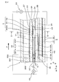
- FIG. 1 is an explanatory view showing a cross section of a sensor element in Embodiment 1.
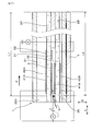
- 2 is a cross-sectional view taken along line II-II in FIG.
- FIG. 3 is an explanatory diagram showing a cross section of the sensor element in the first embodiment.
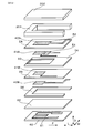
- FIG. 4 is an exploded perspective view schematically showing the sensor element in the first embodiment.
- FIG. 5 is a cross-sectional view of a gas sensor including a sensor element in Embodiment 1.
- FIG. 6 is an explanatory diagram showing a cross section of another sensor element in the first embodiment.
- FIG. 7 is an explanatory diagram showing a cross section of another sensor element in the first embodiment.
- FIG. 8 is an explanatory diagram showing a cross section of another sensor element in the first embodiment.
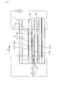
- FIG. 9 is an explanatory diagram illustrating operations of the pump cell and the sensor cell in the first embodiment.
- FIG. 10 is an explanatory view showing a cross section of the sensor element in the second embodiment.
- FIG. 11 is a graph showing the relationship between the ratio of the value (S1 / L1) in the first reference gas chamber to the value (S2 / L2) in the second reference gas chamber in the confirmation test 1 and the deviation amount of the sensor output.
- FIG. 12 is a graph showing the relationship between the sum of the value (S1 / L1) and the value (S2 / L2) and the amount of deviation of the sensor output in the confirmation test 2.
- the gas sensor 10 of this embodiment includes a sensor element 1 for measuring the concentration of a specific gas component in the measurement gas G containing oxygen.
- the sensor element 1 includes a first solid electrolyte body 2A and a second solid electrolyte body 2B having oxygen ion conductivity, a measurement gas chamber 3 into which a measurement gas G is introduced, and a reference gas A.
- the first solid electrolyte body 2 ⁇ / b> A is disposed between the first reference gas chamber 31 and the measurement gas chamber 3.
- the first solid electrolyte body 2 ⁇ / b> A has a first main surface 21 facing the first reference gas chamber 31 and a second main surface 22 facing the measurement gas chamber 3.
- the second solid electrolyte body 2B is arranged to face the first solid electrolyte body 2A with the measurement gas chamber 3 interposed therebetween.
- the second solid electrolyte body 2 ⁇ / b> B has a first main surface 23 facing the measurement gas chamber 3 and a second main surface 24 facing the second reference gas chamber 32.
- the first pump cell 4A is formed on the first reference electrode 42A formed on the first main surface 21 of the first solid electrolyte body 2A and on the second main surface 22 of the first solid electrolyte body 2A.
- the first pump cell 4A is used to adjust the oxygen concentration in the measurement gas chamber 3 by energization between the first reference electrode 42A and the first pump electrode 41A.
- the second pump cell 4B includes a second pump electrode 41B formed at a position facing the first pump electrode 41A on the first main surface 23 of the second solid electrolyte body 2B, and a second main electrode of the second solid electrolyte body 2B.
- the second reference electrode 42B formed on the surface 24 and a part 201B of the second solid electrolyte body sandwiched between the second pump electrode 41B and the second reference electrode 42B.
- the second pump cell 4B is used to adjust the oxygen concentration in the measurement gas chamber 3 by energization between the second reference electrode 42B and the second pump electrode 41B.
- the sensor cell 5 includes a third reference electrode 52 formed on the first main surface 21 of the first solid electrolyte body 2A, and a second main surface 22 of the first solid electrolyte body 2A.
- the sensor cell 5 measures the concentration of a specific gas component in the measurement gas G after the oxygen concentration is adjusted by the pump cells 4A and 4B based on the current flowing between the third reference electrode 52 and the sensor electrode 51. Used for.
- the heater 6 is disposed to face the second main surface 24 of the second solid electrolyte body 2B.
- the first average cross-sectional area S1 orthogonal to the flow direction F of the first reference gas chamber 31 is divided by the first length L1 of the first reference gas chamber 31 in the flow direction F.
- the value is S1 / L1.
- a value obtained by dividing the second average cross-sectional area S2 orthogonal to the flow direction F of the second reference gas chamber 32 by the second length L2 of the flow direction F of the second reference gas chamber 32 is S2 / L2. .
- S1 / L1 is larger than S2 / L2.
- the gas sensor 10 of this embodiment will be described in further detail.
- the gas sensor 10 is arranged and used in an exhaust passage of an internal combustion engine in a vehicle.
- the exhaust gas flowing through the exhaust passage is used as a measurement gas G, and the atmosphere having a constant oxygen concentration is used as a reference gas A.
- the concentration of NOx (nitrogen oxide) as a specific gas contained in the exhaust gas is measured.
- the gas sensor 10 includes a sensor element 1, a housing 11, insulators 12 and 13, a contact terminal 14, a lead wire 15, a cover 16, a bush 17, double covers 18A and 18B, and the like.
- the sensor element 1 is held by an insulator 12, and the insulator 12 is held by a housing 11.
- the gas sensor 10 is attached to the exhaust passage by the housing 11, and the tip of the sensor element 1 is disposed in the exhaust passage.
- double covers 18 ⁇ / b> A and 18 ⁇ / b> B that cover the tip of the sensor element 1 are attached to the housing 11.
- the solid electrolyte bodies 2 ⁇ / b> A and 2 ⁇ / b> B are formed of plate-shaped yttria-stabilized zirconia.
- the measurement gas chamber 3 is formed by being sandwiched between the second main surface 22 of the first solid electrolyte body 2A and the first main surface 23 of the second solid electrolyte body 2B, and includes the pump electrodes 41A and 41B and the sensor.
- the electrode 51 is disposed in the measurement gas chamber 3.
- the measurement gas chamber 3 is surrounded and formed by a diffusion resistance layer 33 that allows the measurement gas G to pass at a predetermined diffusion rate and an insulator 34 made of ceramics such as alumina.
- the diffusion resistance layer 33 is made of porous ceramics.
- the measurement gas G passes through the diffusion resistance layer 33 and is introduced into the measurement gas chamber 3.
- a cutout for forming the measurement gas chamber 3 is formed in the insulator 34.
- the sensor element 1 is formed in an elongated shape, and the diffusion resistance layer 33 is provided at the tip of the elongated sensor element 1.
- the measurement gas G is introduced into the measurement gas chamber 3 from the diffusion resistance layer 33 at the tip of the sensor element 1, and flows along the longitudinal direction L of the elongated sensor element 1 in the measurement gas chamber 3.
- the flow direction F is a direction from the distal end side to the proximal end side along the longitudinal direction L of the elongated sensor element 1.
- a first reference gas chamber 31 into which the reference gas A is introduced is formed adjacent to the first main surface 21 of the first solid electrolyte body 2A.
- the first reference electrode 42A and the third reference electrode 52 are Arranged in the first reference gas chamber 31.
- the first reference gas chamber 31 is formed surrounded by insulators 351 and 352 made of ceramics such as alumina.
- the insulator 351 has a notch for forming the first reference gas chamber 31.
- a second reference gas chamber 32 into which the reference gas A is introduced is formed adjacent to the second main surface 24 of the second solid electrolyte body 2B, and the second reference electrode 42B is formed in the second reference gas chamber 32. Is arranged.
- the second reference gas chamber 32 is formed to be surrounded by the heater 6 and an insulator 36 made of ceramics such as alumina. A cutout for forming the second reference gas chamber 32 is formed in the insulator 36.
- the first pump cell 4A and the second pump cell 4B have a voltage between the first pump electrode 41A and the first reference electrode 42A and between the second pump electrode 41B and the second reference electrode 42B.
- a voltage application circuit 43 for applying is connected.
- the voltage application circuit 43 is provided in the control unit (SCU) of the gas sensor 10.
- the SCU operates in response to a command from an internal combustion engine control unit (ECU).
- ECU internal combustion engine control unit
- the first pump electrode 41A and the second pump electrode 41B are formed to have the same size and are arranged at the same position in the flow direction F.
- the position of the first pump electrode 41A in the flow direction F and the position of the second pump electrode 41B in the flow direction F may be different from each other.
- the size of the first pump electrode 41A and the size of the second pump electrode 41B may be different from each other.
- the sensor cell 5 detects a current flowing between the electrodes 51 and 52 in a state where a predetermined voltage is applied between the sensor electrode 51 and the third reference electrode 52.
- a current detection circuit 53 is connected.
- oxygen ions permeate from the sensor electrode 51 to the third reference electrode 52 through the first solid electrolyte body 2A. The current is detected by the current detection circuit 53.
- the third reference electrode 52 of this embodiment is formed integrally with the first reference electrode 42A of the first pump cell 4A. As shown in FIG. 8, the third reference electrode 52 may be formed separately from the first reference electrode 42A at a position facing the sensor electrode 51 via the first solid electrolyte body 2A.
- the heater 6 includes a heating element 61 that generates heat when energized, and a ceramic substrate 62 in which the heating element 61 is embedded.
- the heating element 61 When a voltage is applied to the heating element 61 of the heater 6, the heating element 61 generates heat and the sensor element 1 is heated.
- the gas sensor 10 is started, the solid electrolyte bodies 2A and 2B, the pump cells 4A and 4B, and the sensor cell 5 are activated by the heating of the heater 6.
- the temperature of the sensor element 1 is controlled by the heater 6.
- the voltage applied to the heating element 61 of the heater 6 is adjusted so as to keep the temperature of the sensor element 1 at a predetermined target temperature.
- the first reference gas chamber 31 of this embodiment has an upstream end in the flow direction F of the measurement gas G closed by an insulator 351, and an end on the downstream side in the flow direction F.
- the part is formed in an open state.
- the second reference gas chamber 32 is formed in a state where the upstream end in the flow direction F of the measurement gas G is closed by the insulator 36 and the downstream end in the flow direction F is opened.
- the first length L1 of the first reference gas chamber 31 of the present embodiment is the length in the flow direction F of the notch formed in the insulator 351. In other words, the end surface inside the longitudinal direction L of the insulator 351. To the base end of the insulator 351 (or sensor element 1). Further, the second length L2 of the second reference gas chamber 32 of the present embodiment is the length in the flow direction F of the notch formed in the insulator 36. In other words, the second reference gas chamber 32 is located on the inner side of the insulator 36 in the longitudinal direction L. This is the length from the end surface to the base end of the insulator 36 (or sensor element 1).
- the first reference gas chamber 31 and the second reference gas chamber 32 of this embodiment are formed in a straight line along the longitudinal direction L, and the first length L1 and the second length L2 are the same.
- At least one base end portion of the first reference gas chamber 31 and the second reference gas chamber 32 is not formed up to the base end of the sensor element 1 and is laterally formed at an intermediate portion in the longitudinal direction L of the sensor element 1. It can also be in an open state. In this case, one of the first length L1 and the second length L2 may be shorter than the other.
- the reason why the first average cross-sectional area S1 is divided by the first length L1 and the second average cross-sectional area S2 is divided by the second length L2 is that when each of the lengths L1 and L2 becomes longer, the reference gas A is changed to each reference gas chamber. This is because the resistance (or loss) for flowing into 31 and 32 increases. Therefore, instead of directly comparing the first average cross-sectional area S1 and the second average cross-sectional area S2, the first average cross-sectional area S1 is also taken into consideration when the first length L1 and the second length L2 are different. Is divided by the first length L1 and the value S2 / L2 obtained by dividing the second average cross-sectional area S2 by the second length L2.
- the first average cross-sectional area S1 of the first reference gas chamber 31 does not consider the thickness of the first reference electrode 42A, and the first main surface 21 and the insulator 352 of the first solid electrolyte body 2A.
- the average value of values obtained by the product of the distance in the stacking direction D between the inner surface and the distance in the width direction W of the notch in the insulator 351 is obtained.
- the second average cross-sectional area S2 of the second reference gas chamber 32 does not take into account the thickness of the second reference electrode 42B, and is between the second main surface 24 of the second solid electrolyte body 2B and the inner surface of the ceramic substrate 62.
- the average value of the values obtained by the product of the distance in the stacking direction D between them and the distance in the width direction W of the notch in the insulator 36 is obtained.
- the stacking direction D refers to the direction in which the solid electrolyte bodies 2A, 2B and the insulators 34, 351, 352, 36 are stacked.
- the width direction W refers to a direction orthogonal to the longitudinal direction L (or the flow direction F of the measurement gas G) and the stacking direction D.
- the distance in the stacking direction D between the first main surface 21 of the first solid electrolyte body 2A and the inner surface of the insulator 352 and the distance in the width direction W of the notch in the insulator 351 are made constant. ing.
- the distance in the stacking direction D between the second main surface 24 of the second solid electrolyte body 2B and the inner surface of the ceramic substrate 62 and the distance in the width direction W of the notch in the insulator 36 are made constant. ing.
- the cross-sectional areas perpendicular to the flow direction F of the first reference gas chamber 31 and the second reference gas chamber 32 are preferably constant, but are not necessarily constant depending on how the sensor element 1 is manufactured.
- a curved corner 355 may be formed on the inner wall of the first reference gas chamber 31 that forms the upstream end in the flow direction F.
- the curved corner portion 355 is formed when a portion corresponding to the first reference gas chamber 31 is removed by a tool or the like when a ceramic sheet in which the insulator 351 and the insulator 352 are integrated is used. Part.
- the value S1 / L1 in the first reference gas chamber 31 is 2.6 times or more and 70 times or less than the value S2 / L2 in the second reference gas chamber 32. Moreover, the sum total of S1 / L1 and S2 / L2 is 0.006 mm or more. Further, the first length L1 of the first reference gas chamber 31 and the second length L2 of the second reference gas chamber 32 are used to further promote the supply of the reference gas A to the reference electrodes 42A, 42B, 52. It is preferable to be 80 mm or less.
- the value S1 / L1 in the first reference gas chamber 31 facing the first main surface 21 of the first solid electrolyte body 2A provided with the sensor cell 5 is the second solid electrolyte. It is larger than the value S2 / L2 in the second reference gas chamber 32 facing the second main surface 24 of the body 2B.
- each value S1 / L1, S2 / L2 is a scale indicating the ease of introduction of the reference gas A into the reference gas chambers 31 and 32.
- Each value S1 / L1, S2 / L2 increases as the average cross-sectional areas S1, S2 of the reference gas chambers 31, 32 increase, and decreases as the lengths L1, L2 of the reference gas chambers 31, 32 increase.
- the so-called rich gas is introduced into the measurement gas chamber 3 as the measurement gas G due to the configuration of the sensor element 1, the first reference gas that faces the first main surface 21 of the first solid electrolyte body 2 ⁇ / b> A provided with the sensor cell 5.
- a decrease in the oxygen concentration in the chamber 31 can be suppressed.
- the measurement gas G introduced into the gas sensor 10 fluctuates between the rich gas and the lean gas, it is possible to suppress fluctuations that occur in the sensor output when the concentration of the specific gas component is measured by the sensor cell 5. become.
- the rich gas means that the air-fuel ratio (A / F) that is the mass ratio of air to fuel in the internal combustion engine is richer than the stoichiometric air-fuel ratio that indicates the ratio of air when the fuel is completely burned (fuel ratio). It means the exhaust gas when it is on the side where the ratio is high.
- lean gas refers to exhaust gas when the air-fuel ratio in the internal combustion engine is on the lean side (the side with the larger air ratio) than the stoichiometric air-fuel ratio.
- exhaust gas after being burned with rich gas or lean gas is introduced as the measurement gas G.
- the reason why the variation in sensor output can be suppressed by the configuration of the sensor element 1 is not necessarily clear, but is considered as follows.
- rich gas G1 containing CO, HC, H 2 or the like is introduced into the measurement gas chamber 3
- CO and HC in the rich gas G1 are converted into CO 2 and H 2 O.
- the measurement gas chamber 3 is supplied with oxygen from the first reference gas chamber 31 and the second reference gas chamber 32 by the first pump cell 4A and the second pump cell 4B as indicated by arrows T1 and T2 in FIG. .
- the oxygen concentration in the first reference gas chamber 31 and the second reference gas chamber 32 tends to decrease.
- the potential of the third reference electrode 52 changes, and the sensor output changes.
- NOx decomposition reaction may be performed and H 2 O electrolysis may also be performed.
- the first solid electrolyte body 2A as shown by an arrow T3 in FIG. 9, from the measurement gas chamber 3 to the first reference gas chamber 31, oxygen ions at the time of NOx decomposition and oxygen at the time of H 2 O decomposition Conduction with ions.
- the oxygen concentration in the first reference gas chamber 31 is lowered, it is considered that the electrolysis of H 2 O is promoted. Therefore, in the gas sensor 10 of this embodiment, the value S1 / L1 in the first reference gas chamber 31 is made larger than the value S2 / L2 in the second reference gas chamber 32, whereby the oxygen in the first reference gas chamber 31 is increased.
- the formation length of the pump cells 4A and 4B in the flow direction F is shortened.
- the time until the measurement gas G whose oxygen concentration is adjusted by the pump electrodes 41A and 41B of the pump cells 4A and 4B reaches the sensor electrode 51 of the sensor cell 5 is shortened, and the specific gas concentration in the measurement gas G is reduced. High responsiveness of measurement can be maintained.
- Embodiment 2 In this embodiment, another aspect of the heater 6 is shown. In this embodiment, the arrangement position of the heater 6 is different from that in the first embodiment. As shown in FIG. 10, the heater 6 is disposed to face the first main surface 21 of the first solid electrolyte body 2A. Other configurations are the same as those of the first embodiment. Of the reference numerals used in the second and subsequent embodiments, the same reference numerals as those used in the above-described embodiments represent the same components as those in the above-described embodiments unless otherwise indicated.
- the heater 6 in the gas sensor 10 of the present embodiment is disposed to face the first main surface 21 of the first solid electrolyte body 2A where the sensor cell 5 is formed. Therefore, compared with the case of Embodiment 1 where the heater 6 is arranged facing the second main surface 24 of the second solid electrolyte body 2B where the sensor cell 5 is not formed, the arrangement position of the sensor cell 5 is arranged. It is possible to approach the position, and heat generated when the heater 6 is operated can be quickly transferred to the sensor cell 5 when the gas sensor 10 is started and used. Thereby, even when the ambient temperature of the gas sensor 10 changes transiently, it becomes easy to keep the temperature of the sensor cell 5 within the target temperature range. As a result, the temperature fluctuation of the sensor cell 5 is suppressed, and the measurement accuracy of the specific gas concentration in the measurement gas G by the sensor cell 5 can be improved. In addition, the same effects as those of the first embodiment can be obtained.
- the total S1 / L1 + S2 / L2 of the value S1 / L1 in the first reference gas chamber 31 and the value S2 / L2 in the second reference gas chamber 32 in each sample was 0.008 mm.
- the total S1 + S2 of the first average cross-sectional area S1 of the first reference gas chamber 31 and the second average cross-sectional area S2 of the second reference gas chamber 32 is 0.36 mm 2, and the first length of the first reference gas chamber 31 is The second length L2 of L1 and the second reference gas chamber 32 was 45 mm.
- the heater 6 of each sample was heated until the temperature of the sensor cell 5 of each sample reached 750 ° C.
- the oxygen concentration is 21%
- the nitric oxide concentration is 400 ppm
- the balance is nitrogen for the elapsed time of 0 to 600 seconds.
- Measurement gas G was supplied.
- the oxygen concentration is 0%
- the nitric oxide concentration is 400 ppm
- the carbon monoxide concentration is 1.5%
- the hydrogen concentration is passed to the measurement gas chamber 3 of each sample.
- a measuring gas G having a concentration of 4% and a propane concentration of 2%.
- FIG. 11 shows the deviation of the sensor output of each sample when the measurement gas G is changed to lean gas, rich gas, and lean gas.
- the deviation amount of the sensor output of each sample is determined to be 0. which is a criterion when (S1 / L1) / (S2 / L2) is 2.6 times or more and 70 times or less. Within 1 ⁇ A.
- the deviation amount of the sensor output of each sample markedly exceeded the judgment criterion of 0.1 ⁇ A when (S1 / L1) / (S2 / L2) was less than 2.6 times. This is because the value S1 / L1 in the first reference gas chamber 31 is not sufficiently larger than the value S2 / L2 in the second reference gas chamber 32, so that the oxygen concentration in the first reference gas chamber 31 decreases. This is probably because H 2 O was electrolyzed in the sensor cell 5.
- the deviation amount of the sensor output of each sample was within 0.1 ⁇ A which is a criterion when S1 / L1 + S2 / L2 is 0.006 mm or more.
- the deviation amount of the sensor output of each sample markedly exceeds 0.1 ⁇ A which is a criterion. This is because the oxygen amount in the first reference gas chamber 31 and the second reference gas chamber 32 for converting CO in the rich gas into CO 2 is insufficient, and the reaction between CO and NO occurs in the sensor electrode 51 of the sensor cell 5. This is thought to be caused by this. From this, it was found that S1 / L1 + S2 / L2 is preferably set to 0.006 mm or more in order to suppress the fluctuation of the sensor output of the gas sensor 10 to be small.
Landscapes
- Chemical & Material Sciences (AREA)
- Life Sciences & Earth Sciences (AREA)
- Health & Medical Sciences (AREA)
- Analytical Chemistry (AREA)
- Biochemistry (AREA)
- Immunology (AREA)
- Physics & Mathematics (AREA)
- Chemical Kinetics & Catalysis (AREA)
- Molecular Biology (AREA)
- General Health & Medical Sciences (AREA)
- General Physics & Mathematics (AREA)
- Electrochemistry (AREA)
- Pathology (AREA)
- Engineering & Computer Science (AREA)
- Combustion & Propulsion (AREA)
- Mechanical Engineering (AREA)
- General Engineering & Computer Science (AREA)
- Measuring Oxygen Concentration In Cells (AREA)
Priority Applications (2)
| Application Number | Priority Date | Filing Date | Title |
|---|---|---|---|
| DE112017003290.3T DE112017003290T5 (de) | 2016-06-29 | 2017-05-15 | Gassensor |
| US16/313,551 US11209388B2 (en) | 2016-06-29 | 2017-05-15 | Gas sensor |
Applications Claiming Priority (2)
| Application Number | Priority Date | Filing Date | Title |
|---|---|---|---|
| JP2016-128761 | 2016-06-29 | ||
| JP2016128761A JP6640665B2 (ja) | 2016-06-29 | 2016-06-29 | ガスセンサ |
Publications (1)
| Publication Number | Publication Date |
|---|---|
| WO2018003326A1 true WO2018003326A1 (ja) | 2018-01-04 |
Family
ID=60786623
Family Applications (1)
| Application Number | Title | Priority Date | Filing Date |
|---|---|---|---|
| PCT/JP2017/018249 Ceased WO2018003326A1 (ja) | 2016-06-29 | 2017-05-15 | ガスセンサ |
Country Status (4)
| Country | Link |
|---|---|
| US (1) | US11209388B2 (https=) |
| JP (1) | JP6640665B2 (https=) |
| DE (1) | DE112017003290T5 (https=) |
| WO (1) | WO2018003326A1 (https=) |
Families Citing this family (1)
| Publication number | Priority date | Publication date | Assignee | Title |
|---|---|---|---|---|
| WO2020004763A1 (ko) * | 2018-06-29 | 2020-01-02 | 엘지전자 주식회사 | 무선랜 시스템에서의 신호 송수신 방법 및 이를 위한 장치 |
Citations (4)
| Publication number | Priority date | Publication date | Assignee | Title |
|---|---|---|---|---|
| JP2000180411A (ja) * | 1998-12-17 | 2000-06-30 | Riken Corp | 窒素酸化物センサ |
| JP2001159620A (ja) * | 1999-09-22 | 2001-06-12 | Ngk Insulators Ltd | ガス分析計およびその校正方法 |
| JP2002340845A (ja) * | 2001-05-17 | 2002-11-27 | Denso Corp | ガスセンサ素子及びその製造方法 |
| JP2013088119A (ja) * | 2011-10-13 | 2013-05-13 | Nippon Soken Inc | ガスセンサ素子および内燃機関用ガスセンサ |
Family Cites Families (7)
| Publication number | Priority date | Publication date | Assignee | Title |
|---|---|---|---|---|
| JP4563606B2 (ja) * | 2000-03-31 | 2010-10-13 | 株式会社デンソー | 積層型センサ素子 |
| JP2002071641A (ja) * | 2000-08-28 | 2002-03-12 | Riken Corp | 複合ガス検知装置 |
| US6787014B2 (en) * | 2001-10-09 | 2004-09-07 | Kabushiki Kaisha Riken | Gas-detecting element and gas-detecting device comprising same |
| JP2004037100A (ja) * | 2002-06-28 | 2004-02-05 | Denso Corp | ガスセンサ素子 |
| DE10339976A1 (de) * | 2002-08-29 | 2004-04-22 | Denso Corp., Kariya | Gasmessfühler |
| JP2007255985A (ja) * | 2006-03-22 | 2007-10-04 | Denso Corp | ガスセンサ素子 |
| JP6422348B2 (ja) | 2015-01-09 | 2018-11-14 | 有限会社豊栄産業 | 放射線遮蔽用コンクリート組成物及び放射線遮蔽用コンクリート組成物により形成された放射性物質保管用容器 |
-
2016
- 2016-06-29 JP JP2016128761A patent/JP6640665B2/ja active Active
-
2017
- 2017-05-15 US US16/313,551 patent/US11209388B2/en not_active Expired - Fee Related
- 2017-05-15 WO PCT/JP2017/018249 patent/WO2018003326A1/ja not_active Ceased
- 2017-05-15 DE DE112017003290.3T patent/DE112017003290T5/de active Pending
Patent Citations (4)
| Publication number | Priority date | Publication date | Assignee | Title |
|---|---|---|---|---|
| JP2000180411A (ja) * | 1998-12-17 | 2000-06-30 | Riken Corp | 窒素酸化物センサ |
| JP2001159620A (ja) * | 1999-09-22 | 2001-06-12 | Ngk Insulators Ltd | ガス分析計およびその校正方法 |
| JP2002340845A (ja) * | 2001-05-17 | 2002-11-27 | Denso Corp | ガスセンサ素子及びその製造方法 |
| JP2013088119A (ja) * | 2011-10-13 | 2013-05-13 | Nippon Soken Inc | ガスセンサ素子および内燃機関用ガスセンサ |
Also Published As
| Publication number | Publication date |
|---|---|
| US20190227027A1 (en) | 2019-07-25 |
| DE112017003290T5 (de) | 2019-03-14 |
| JP6640665B2 (ja) | 2020-02-05 |
| JP2018004349A (ja) | 2018-01-11 |
| US11209388B2 (en) | 2021-12-28 |
Similar Documents
| Publication | Publication Date | Title |
|---|---|---|
| US20220113280A1 (en) | Gas sensor | |
| CN110672698B (zh) | 气体传感器及传感器元件 | |
| CN107941885A (zh) | 气体传感器 | |
| JP7122958B2 (ja) | センサ素子及びガスセンサ | |
| CN115087863B (zh) | 气体传感器元件 | |
| JP7547251B2 (ja) | センサ素子及びガスセンサ | |
| WO2022123866A1 (ja) | ガスセンサ | |
| JP6731283B2 (ja) | ガスセンサ | |
| JP2020003284A (ja) | ガスセンサ | |
| US20250258129A1 (en) | Gas sensor and concentration measurement method using gas sensor | |
| US20170122897A1 (en) | Gas sensor | |
| JP6640665B2 (ja) | ガスセンサ | |
| JP7737921B2 (ja) | センサ素子及びセンサ素子を用いたガス検出方法 | |
| US11940406B2 (en) | Sensor element and gas sensor | |
| US10934958B2 (en) | Air-fuel ratio detection device and air-fuel ratio detection method | |
| US20210302358A1 (en) | Sensor element and gas sensor | |
| US20240011938A1 (en) | Sensor element and gas sensor | |
| JP2022153758A (ja) | センサ素子及びガスセンサ | |
| JP2022153759A (ja) | センサ素子及びガスセンサ | |
| WO2025191992A1 (ja) | ガスセンサ | |
| JP2017146199A (ja) | 硫黄酸化物検出装置 | |
| JP2024061252A (ja) | ガスセンサ | |
| CN119998655A (zh) | 气体传感器 | |
| JP2024119106A (ja) | ガスセンサ | |
| JP2017075794A (ja) | センサ制御装置 |
Legal Events
| Date | Code | Title | Description |
|---|---|---|---|
| 121 | Ep: the epo has been informed by wipo that ep was designated in this application |
Ref document number: 17819693 Country of ref document: EP Kind code of ref document: A1 |
|
| 122 | Ep: pct application non-entry in european phase |
Ref document number: 17819693 Country of ref document: EP Kind code of ref document: A1 |