WO2018003092A1 - 非接触電力伝送装置、非接触電力伝送システム、及び誘導加熱調理器 - Google Patents
非接触電力伝送装置、非接触電力伝送システム、及び誘導加熱調理器 Download PDFInfo
- Publication number
- WO2018003092A1 WO2018003092A1 PCT/JP2016/069532 JP2016069532W WO2018003092A1 WO 2018003092 A1 WO2018003092 A1 WO 2018003092A1 JP 2016069532 W JP2016069532 W JP 2016069532W WO 2018003092 A1 WO2018003092 A1 WO 2018003092A1
- Authority
- WO
- WIPO (PCT)
- Prior art keywords
- coil
- inverter circuit
- power transmission
- power
- impedance
- Prior art date
- Legal status (The legal status is an assumption and is not a legal conclusion. Google has not performed a legal analysis and makes no representation as to the accuracy of the status listed.)
- Ceased
Links
Images



Classifications
-
- H—ELECTRICITY
- H05—ELECTRIC TECHNIQUES NOT OTHERWISE PROVIDED FOR
- H05B—ELECTRIC HEATING; ELECTRIC LIGHT SOURCES NOT OTHERWISE PROVIDED FOR; CIRCUIT ARRANGEMENTS FOR ELECTRIC LIGHT SOURCES, IN GENERAL
- H05B6/00—Heating by electric, magnetic or electromagnetic fields
- H05B6/02—Induction heating
- H05B6/10—Induction heating apparatus, other than furnaces, for specific applications
- H05B6/12—Cooking devices
- H05B6/1209—Cooking devices induction cooking plates or the like and devices to be used in combination with them
- H05B6/1236—Cooking devices induction cooking plates or the like and devices to be used in combination with them adapted to induce current in a coil to supply power to a device and electrical heating devices powered in this way
-
- H—ELECTRICITY
- H02—GENERATION; CONVERSION OR DISTRIBUTION OF ELECTRIC POWER
- H02J—ELECTRIC POWER NETWORKS; CIRCUIT ARRANGEMENTS OR SYSTEMS FOR SUPPLYING OR DISTRIBUTING ELECTRIC POWER; SYSTEMS FOR STORING ELECTRIC ENERGY
- H02J50/00—Circuit arrangements or systems for wireless supply or distribution of electric power
- H02J50/10—Circuit arrangements or systems for wireless supply or distribution of electric power using inductive coupling
- H02J50/12—Circuit arrangements or systems for wireless supply or distribution of electric power using inductive coupling of the resonant type
-
- H—ELECTRICITY
- H01—ELECTRIC ELEMENTS
- H01F—MAGNETS; INDUCTANCES; TRANSFORMERS; SELECTION OF MATERIALS FOR THEIR MAGNETIC PROPERTIES
- H01F38/00—Adaptations of transformers or inductances for specific applications or functions
- H01F38/14—Inductive couplings
-
- H—ELECTRICITY
- H02—GENERATION; CONVERSION OR DISTRIBUTION OF ELECTRIC POWER
- H02J—ELECTRIC POWER NETWORKS; CIRCUIT ARRANGEMENTS OR SYSTEMS FOR SUPPLYING OR DISTRIBUTING ELECTRIC POWER; SYSTEMS FOR STORING ELECTRIC ENERGY
- H02J50/00—Circuit arrangements or systems for wireless supply or distribution of electric power
- H02J50/80—Circuit arrangements or systems for wireless supply or distribution of electric power involving the exchange of data, concerning supply or distribution of electric power, between transmitting devices and receiving devices
-
- H—ELECTRICITY
- H05—ELECTRIC TECHNIQUES NOT OTHERWISE PROVIDED FOR
- H05B—ELECTRIC HEATING; ELECTRIC LIGHT SOURCES NOT OTHERWISE PROVIDED FOR; CIRCUIT ARRANGEMENTS FOR ELECTRIC LIGHT SOURCES, IN GENERAL
- H05B6/00—Heating by electric, magnetic or electromagnetic fields
- H05B6/02—Induction heating
- H05B6/06—Control, e.g. of temperature, of power
- H05B6/062—Control, e.g. of temperature, of power for cooking plates or the like
-
- H—ELECTRICITY
- H05—ELECTRIC TECHNIQUES NOT OTHERWISE PROVIDED FOR
- H05B—ELECTRIC HEATING; ELECTRIC LIGHT SOURCES NOT OTHERWISE PROVIDED FOR; CIRCUIT ARRANGEMENTS FOR ELECTRIC LIGHT SOURCES, IN GENERAL
- H05B2213/00—Aspects relating both to resistive heating and to induction heating, covered by H05B3/00 and H05B6/00
- H05B2213/05—Heating plates with pan detection means
Definitions
- the present invention relates to a non-contact power transmission device, a non-contact power transmission system, and an induction heating cooker for transmitting power to a power receiving device.
- the non-contact power transmission device described in Patent Document 1 is based on a change in input current value when the conduction time of a semiconductor switch is changed. Power receiving device).
- the material, shape, size, etc. of the object to be heated by induction vary, and there are objects to be heated whose relationship between the change in the conduction time of the semiconductor switch and the change in the input current value is close to the characteristics of the electrical equipment. To do. For this reason, an error may occur in the determination result of the load determination unit.
- there is an error in the determination result of the load determination unit there is a problem in that appropriate electric power cannot be supplied to the electrical device.
- the present invention has been made to solve the above-described problems, and provides a non-contact power transmission device, a non-contact power transmission system, and an induction heating cooker that can supply appropriate power to a power receiving device. Is.
- a non-contact power transmission device is a non-contact power transmission device for transmitting power to a power receiving device having a resonance circuit, the coil generating a high-frequency magnetic field by supplying a high-frequency current,
- a control body configured to support the power receiving device in a high-frequency magnetic field; an inverter circuit that supplies the high-frequency current to the coil; and a control device that controls driving of the inverter circuit.
- the non-contact power transmission device When the impedance on the output side of the inverter circuit has resonance characteristics, the non-contact power transmission device according to the present invention performs a power transmission operation for transmitting power to the power receiving device, so that appropriate power can be supplied to the power receiving device. it can.
- FIG. (Constitution) 1 is an exploded perspective view showing an induction heating cooker according to Embodiment 1 of the present invention.
- an induction heating cooker 100 has a top plate 4 on which an object to be heated 5 such as a pan is placed.
- power receiving device 200 is also placed on top plate 4 as will be described later with reference to FIG.
- Induction heating cooker 100 according to the first embodiment functions as a non-contact power device that transmits power to power receiving device 200.
- the top plate 4 includes a first induction heating port 1 and a second induction heating port 2 as heating ports for induction heating of the article 5 to be heated.
- the first induction heating port 1 and the second induction heating port 2 are juxtaposed in the lateral direction on the front side of the top plate 4. Moreover, the induction heating cooking appliance 100 which concerns on this Embodiment 1 is also provided with the 3rd induction heating port 3 as a 3rd heating port.
- the third induction heating port 3 is provided on the back side of the first induction heating port 1 and the second induction heating port 2 and at a substantially central position in the lateral direction of the top plate 4. Below each of the first induction heating port 1, the second induction heating port 2, and the third induction heating port 3, a first induction heating coil 11 that heats an object to be heated placed on the heating port.
- a second induction heating coil 12 and a third induction heating coil 13 are provided below each of the first induction heating port 1, the second induction heating port 2, and the third induction heating port 3.
- the entire top plate 4 is made of a material that transmits infrared rays, such as heat-resistant tempered glass or crystallized glass.
- a circular pan position display indicating the position is formed by applying paint or printing.
- An operation unit 40 is provided as an input device for setting a cooking menu (water heating mode, fried food mode, etc.) and the like.
- the operation unit 40 is divided for each induction heating coil to form the operation unit 40a, the operation unit 40b, and the operation unit 40c.
- a display unit 41 is provided as an informing means for displaying the operation state of each induction heating coil, the input from the operation unit 40, the operation content, and the like.
- the display unit 41 is divided for each induction heating coil to form a display unit 41a, a display unit 41b, and a display unit 41c.
- the operation part 40 and the display part 41 are not specifically limited when providing for every induction heating coil as mentioned above, when providing as a thing common to each induction heating coil, etc.
- the operation unit 40 includes, for example, a mechanical switch such as a push switch and a tact switch, a touch switch that detects an input operation based on a change in the capacitance of the electrode, and the like.
- the display unit 41 includes, for example, an LCD (Liquid Crystal Device), an LED, and the like.
- the operation unit 40 and the display unit 41 may be a display operation unit 43 configured integrally with them.
- the display operation unit 43 is configured by, for example, a touch panel in which touch switches are arranged on the upper surface of the LCD.
- the first induction heating coil 11, the second induction heating coil 12, and the third induction heating coil 13 are configured as follows, for example.
- the 1st induction heating coil 11, the 2nd induction heating coil 12, and the 3rd induction heating coil 13 have the same structure. For this reason, the structure of the 1st induction heating coil 11 is demonstrated below representatively.
- FIG. 2 is a plan view showing the induction heating coil of the induction heating cooker according to Embodiment 1 of the present invention.
- the first induction heating coil 11 is composed of a plurality of coils arranged substantially concentrically.
- the first induction heating coil 11 is composed of quadruple coils 11-1 to 11-4 arranged substantially concentrically. These coils 11-1 to 11-4 are connected together.
- the coils 11-1 to 11-4 are configured by winding a conductive wire made of an arbitrary metal (for example, copper, aluminum, etc.) with an insulating film.
- a high frequency magnetic field is generated from each induction heating coil by supplying high frequency power to the first induction heating coil 11, the second induction heating coil 12, and the third induction heating coil 13 by the drive circuit 50.
- the detailed configuration of the drive circuit 50 will be described later.
- a control unit 45 for controlling the entire operation of the induction heating cooker 100 including the drive circuit 50 is accommodated in the induction heating cooker 100.
- the control unit 45 is a dedicated hardware or a CPU (Central Processing Unit) that executes a program stored in the memory 48 (see FIG. 3), a central processing unit, a processing unit, an arithmetic unit, a microprocessor, a microcomputer, and a processor. Consists of).
- the control unit 45 may be, for example, a single circuit, a composite circuit, an application specific integrated circuit (ASIC), a field-programmable gate array (FPGA), or a combination of these. Applicable.
- Each functional unit realized by the control unit 45 may be realized by individual hardware, or each functional unit may be realized by one piece of hardware.
- each function executed by the control unit 45 is realized by software, firmware, or a combination of software and firmware.
- Software and firmware are described as programs and stored in the memory 48.
- the CPU implements each function of the control unit 45 by reading and executing the program stored in the memory 48.
- the memory 48 is a nonvolatile or volatile semiconductor memory such as a RAM, a ROM, a flash memory, an EPROM, or an EEPROM.
- a part of the function of the control unit 45 may be realized by dedicated hardware, and a part may be realized by software or firmware.
- FIG. 3 is a block diagram showing the configuration of the induction heating cooker according to Embodiment 1 of the present invention and the power receiving device placed on the top plate of the induction heating cooker.
- FIG. 3 shows a state where the power receiving device 200 is placed in the first induction heating port 1 on the top plate 4 of the induction heating cooker 100.
- the induction heating cooker 100 that functions as a non-contact power transmission device and the power receiving device 200 constitute a non-contact power transmission system.
- the power receiving apparatus 200 is, for example, a cooking device (such as a fryer, a steamer, a roaster, or a toaster) that performs cooking other than induction heating cooking. Further, for example, the power receiving device 200 is a cooking device (a blender, a mixer, a mill, a frothing device, a food processor, or the like) that prepares and prepares dishes.
- a cooking device such as a fryer, a steamer, a roaster, or a toaster
- the power receiving device 200 is a cooking device (a blender, a mixer, a mill, a frothing device, a food processor, or the like) that prepares and prepares dishes.
- the power receiving device 200 includes a power receiving coil 65 that receives power by electromagnetic induction, a power receiving circuit 81 that rectifies and smoothes the power received by the power receiving coil 65, and a load circuit 82 that is connected to the output side of the power receiving circuit 81. And a secondary control unit 83 that controls the power receiving circuit 81 and the load circuit 82.
- the power receiving device 200 is placed on the top plate 4 of the induction heating cooker 100 and receives electric power from the induction heating cooker 100 in a non-contact manner. That is, a high frequency magnetic field is generated from the first induction heating coil 11 by supplying high frequency power to the first induction heating coil 11 under the top plate 4 of the induction heating cooker 100 by the drive circuit 50. .
- the high-frequency magnetic field is received by a power receiving coil 65 provided in the power receiving device 200, and power is supplied to the power receiving device 200 in a non-contact manner.
- the secondary control unit 83 of the power reception device 200 controls the power reception circuit 81 so that the power received by the power reception coil 65 is supplied to the load circuit 82 with an alternating current.
- the secondary control unit 83 rectifies and smoothes the electric power received by the power receiving coil 65, converts the electric power to an arbitrary alternating current by an inverter circuit or the like, and supplies the alternating current to the load circuit 82.
- the power receiving circuit 81 is controlled.
- the load circuit 82 when the load circuit 82 is a motor load, the load circuit 82 is driven at a variable speed. Note that direct current may be applied to the heater load by rectification and smoothing. Needless to say, the motor load may be driven at a constant speed.
- the power receiving device 200 is preferably provided with an operation unit and a display unit.
- the operation unit for example, start and stop of power supply to the power receiving apparatus 200 are operated.
- the display unit for example, the power receiving state of the power receiving device 200 is displayed.
- the operation unit and the display unit are integrally configured as a display operation unit 84.
- the primary side transmission / reception part 47 may be provided in the induction heating cooker 100, and the secondary side transmission / reception part 85 may be provided in the power receiving apparatus 200.
- the secondary transmission / reception unit 85 outputs a device identification signal of the power receiving device 200 to the primary transmission / reception unit 47.
- the primary side transmission / reception unit 47 receives the control signal output from the secondary side transmission / reception unit 85 and sends it to the control unit 45.
- the power reception coil 65 has the same configuration as that of the first induction heating coil 11, for example.
- ferrite as a magnetic material is disposed below the first induction heating coil 11.
- the shape of the ferrite is, for example, a flat plate shape.
- a protrusion inserted between the coils constituting the first induction heating coil 11 may be provided on the upper surface of the flat ferrite, and the vertical cross-sectional shape of the ferrite may be a convex type, an F type, an E type, or the like.
- ferrite as a magnetic material is arranged on the upper portion of the power receiving coil 65.
- the shape of the ferrite is, for example, a flat plate shape.
- a protrusion inserted between the coils constituting the power receiving coil 65 may be provided on the lower surface of the flat ferrite plate, and the vertical cross-sectional shape of the ferrite may be a convex shape, an F shape, an E shape, or the like.
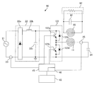
- FIG. 4 is a diagram showing a circuit configuration of the drive circuit of the induction heating cooker and the power receiving device according to Embodiment 1 of the present invention.
- FIG. 4 shows the circuit configuration of the drive circuit 50 of the first induction heating coil 11, the control unit 45, the load determination means in the control unit 45, and the power receiving device 200.
- the drive circuit, the control unit, and the load determination unit connected to the second induction heating coil 12 and the third induction heating coil 13 have the same configuration as the drive circuit 50 and the control unit 45 shown in FIG.
- the drive circuit 50 is a half-bridge drive circuit, and includes a DC power supply circuit 22, an inverter circuit 123, and a power transmission side resonance capacitor 24.
- the input current detection means 23 is composed of, for example, a current sensor, detects a current input from the AC power supply (commercial power supply) 21 to the DC power supply circuit 22, and outputs a voltage signal corresponding to the input current value to the control unit 45. .
- the DC power supply circuit 22 includes a diode bridge 22a, a reactor 22b, and a smoothing capacitor 22c, converts an AC voltage input from the AC power supply 21 into a DC voltage, and outputs the DC voltage to the inverter circuit 123.
- the inverter circuit 123 is a half-bridge type inverter in which IGBTs 123 a and 123 b as switching elements are connected in series to the output of the DC power supply circuit 22.
- diodes 123c and 123d are connected in parallel with the IGBTs 123a and 123b as flywheel diodes, respectively.
- the IGBT 123 a and the IGBT 123 b are driven on and off by a drive signal output from the control unit 45.
- the control unit 45 turns off the IGBT 123b while turning on the IGBT 123a, turns on the IGBT 123b while turning off the IGBT 123a, and outputs a drive signal that turns on and off alternately.
- the inverter circuit 123 converts the DC power output from the DC power supply circuit 22 into AC power having a specified frequency, and supplies power to the resonance circuit including the first induction heating coil 11 and the power transmission side resonance capacitor 24.
- the specified frequency AC power is, for example, high frequency AC power of about 20 kHz to 100 kHz.
- the power transmission side resonance capacitor 24 is connected in series to the first induction heating coil 11, and this resonance circuit has a resonance frequency according to the inductance of the first induction heating coil 11, the capacity of the power transmission side resonance capacitor 24, and the like. .
- a high-frequency current flows through the first induction heating coil 11, and on the top plate 4 immediately above the first induction heating coil 11 by the high-frequency magnetic flux generated by the flowing high-frequency current. Electric power can be transmitted in a non-contact manner to the power receiving coil 65 of the power receiving device 200 placed thereon.
- the IGBTs 123a and 123b which are switching elements, are composed of, for example, a silicon-based semiconductor, but the switching elements may be formed of a wide band gap semiconductor such as silicon carbide or a gallium nitride-based material.
- a wide band gap semiconductor such as silicon carbide or a gallium nitride-based material.
- the coil current detection means 25 is connected to a resonance circuit composed of the first induction heating coil 11 and the power transmission side resonance capacitor 24.
- the coil current detection means 25 is composed of, for example, a current sensor, detects a current flowing through the first induction heating coil 11, and outputs a voltage signal corresponding to the coil current value to the control unit 45.
- FIG. 4 shows a half-bridge drive circuit
- a full-bridge drive circuit composed of four IGBTs and four diodes may be used.
- the power receiving device 200 is provided with a power receiving resonance capacitor 62 that forms a resonance circuit together with the power receiving coil 65.
- the power reception side resonance capacitor 62 is connected in parallel to the power reception coil 65, and this resonance circuit has a resonance frequency corresponding to the inductance of the power reception coil 65, the capacity of the power reception side resonance capacitor 62, and the like.
- the inductance of the power receiving coil 65 is determined by a resonance circuit when the first induction heating coil 11 is magnetically coupled.
- FIG. 4 shows a resonance circuit in which the power reception side resonance capacitor 62 is connected in parallel to the power reception coil 65, it may be a resonance circuit in which the power reception side resonance capacitor 62 is connected in series to the power reception coil 65.
- control unit 45 includes a load determination unit 46.
- the load determination unit 46 determines whether the load placed on the top 4 receives power depending on whether the impedance characteristic on the output side of the inverter circuit 123 has resonance characteristics when the drive frequency of the inverter circuit 123 is changed. It is determined whether or not the device 200 is used.
- the 1st induction heating coil 11, the 2nd induction heating coil 12, and the 3rd induction heating coil 13 are equivalent to the "coil” of this invention.
- the top plate 4 corresponds to the “support” of the present invention.
- the control unit 45 corresponds to a “control device” of the present invention.
- the load determination unit 46 is included in the “control device” of the present invention.
- the display unit 41 corresponds to “notification means” of the present invention.
- the memory 48 corresponds to the “storage means” of the present invention.
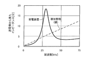
- impedance characteristics Here, impedance characteristics of the power receiving device 200 having a resonance circuit and the object to be heated 5 such as a pan will be described.
- FIG. 5 is a diagram illustrating an example of impedance characteristics between the power receiving apparatus and the object to be heated.
- the horizontal axis indicates the drive frequency of the inverter circuit 123
- the vertical axis indicates the impedance on the output side of the inverter circuit 123 (impedance viewed from the power transmission side).
- the impedance becomes maximum at the resonance frequency of the resonance circuit, and the impedance decreases at a frequency lower than the resonance frequency and a frequency higher than the resonance frequency. That is, in the range higher than the resonance frequency, the impedance when the load is the power receiving device 200 has resonance characteristics in which the impedance increases as the drive frequency decreases.
- the impedance when the load is the power receiving device 200 has a resonance characteristic in which the impedance increases as the drive frequency increases. Furthermore, in the frequency range including the resonance frequency, the impedance when the load is the power receiving device 200 has a resonance characteristic including an increase and a decrease in impedance with a change in the drive frequency.
- the impedance monotonously decreases as the drive frequency decreases. That is, the impedance when the load is the object to be heated 5 has a characteristic that the impedance decreases monotonously as the drive frequency decreases. Further, the impedance when the load is the object to be heated 5 has a characteristic that the impedance increases monotonously as the drive frequency increases.
- the load determination unit 46 provided in the control unit 45 starts a load determination operation based on the operation start signal from the operation unit 40.
- the control unit 45 drives the inverter circuit 123 with a specific drive signal for load determination.
- the load determination unit 46 detects the coil current from the current detection signal of the coil current detection means 25.
- the control unit 45 decreases the drive frequency of the inverter circuit 123 from a high frequency to a low frequency.
- the load determination unit 46 sequentially detects the coil current from the current detection signal of the coil current detection means 25.
- the DC output voltage of the DC power supply circuit 22 is output as a rectangular wave as the output voltage of the inverter circuit 123 by the switching operation of the inverter circuit 123.
- the change in the output voltage of the inverter circuit 123 is small, the change in the coil current flowing through the first induction heating coil 11 is substantially equivalent to the change in the impedance of the load. That is, when the impedance increases, the coil current decreases, and when the impedance decreases, the coil current increases.
- the load determination unit 46 according to the first embodiment performs load determination based on whether or not the coil current has resonance characteristics when the drive frequency of the inverter circuit 123 is changed.
- the load on the top 4 is the power receiving device 200. Is determined.
- the current detection signal of the coil current detection means 25 increases (impedance decreases) as the drive frequency of the inverter circuit 123 decreases, it is determined that the load on the top 4 is the object to be heated 5.
- the drive frequency that is changed in the load determination operation is set to a frequency that is higher than the resonance frequency of the first induction heating coil 11 and the power transmission side resonance capacitor 24.
- the resonance frequency of the first induction heating coil 11 and the power transmission side resonance capacitor 24 is 18 kHz
- the drive frequency changed in the load determination operation is set to 20 kHz or more.
- the range in which the drive frequency of the inverter circuit 123 is changed in the load determination operation may be set to an arbitrary frequency range included in the range of 20 kHz to less than 100 kHz.
- the resonance frequency of the resonance circuit of the power receiving device 200 is about 28 kHz by a learning function (described later) by repetition
- the drive frequency of the inverter circuit 123 is changed from 50 kHz to 20 kHz in the load determination operation. It may be decreased. Thereby, the time of load determination operation
- control unit 45 After performing the above load determination operation, the control unit 45 performs a control operation based on the load determination result.
- the control unit 45 performs a power transmission operation for transmitting power to the power receiving device 200. That is, the control unit 45 controls the drive circuit 50 according to the power transmitted to the power receiving coil 65 and supplies high frequency power to the first induction heating coil 11. As a result, the high frequency power supplied from the first induction heating coil 11 is received by the power receiving coil 65 arranged in the power receiving device 200. The received power is supplied from the power receiving circuit 81 to the load circuit 82, and the load circuit 82 is driven.
- the control unit 45 performs a heating operation for inductively heating the object to be heated 5. That is, the control unit 45 controls the drive circuit 50 according to the heating power to be induction-heated, and performs a heating operation for supplying high-frequency power to the first induction heating coil 11. Thereby, the to-be-heated object 5 arrange
- the control unit 45 supplies power to the power receiving device 200 when the output-side impedance of the inverter circuit 123 has resonance characteristics when the drive frequency of the inverter circuit 123 is changed.
- the power transmission operation is performed. For this reason, appropriate electric power can be supplied to the power receiving apparatus 200.
- the load determination unit 46 determines that the load is the power receiving device 200 when the load determination unit 46 has a resonance characteristic in which the impedance increases as the drive frequency of the inverter circuit 123 decreases. That is, since load determination is performed based on the presence or absence of resonance characteristics that are not present in the heated object 5 such as a pan, the accuracy of load determination can be improved.
- the load determination unit 46 determines that the load is the power receiving device 200 when the coil current has resonance characteristics when the drive frequency of the inverter circuit 123 is changed. For this reason, the configuration required for load determination can be simplified.
- Embodiment 2 a load determination operation for increasing the drive frequency of the inverter circuit 123 from a low frequency to a high frequency will be described.
- the load determination operation in the second embodiment will be described focusing on the differences from the first embodiment.
- the load determination unit 46 provided in the control unit 45 starts a load determination operation based on the operation start signal from the operation unit 40.
- the control unit 45 drives the inverter circuit 123 with a specific drive signal for load determination.
- the load determination unit 46 detects the coil current from the current detection signal of the coil current detection means 25.
- the control unit 45 increases the drive frequency of the inverter circuit 123 from a low frequency to a high frequency.
- the load determination unit 46 sequentially detects the coil current from the current detection signal of the coil current detection means 25.
- the load is the power receiving device 200
- the impedance decreases (current increases) from a certain frequency.
- the heated object 5 or the power receiving device 200 can be determined based on the presence or absence of this resonance characteristic. That is, in the load determination unit 46, when the current detection signal of the coil current detection unit 25 increases (impedance decreases) as the drive frequency of the inverter circuit 123 increases, the load on the top 4 is the power receiving device 200. Is determined. On the other hand, when the current detection signal of the coil current detection means 25 decreases (impedance increases) as the drive frequency of the inverter circuit 123 increases, it is determined that the load on the top 4 is the object to be heated 5.
- the drive frequency that is changed in the load determination operation is set to a frequency that is higher than the resonance frequency of the first induction heating coil 11 and the power transmission side resonance capacitor 24.
- the resonance frequency of the first induction heating coil 11 and the power transmission side resonance capacitor 24 is 18 kHz
- the drive frequency changed in the load determination operation is set to 20 kHz or more.
- the load determination unit 46 determines that the load is the power receiving device 200 when the load determination unit 46 has a resonance characteristic in which the impedance decreases as the drive frequency of the inverter circuit 123 increases. That is, since load determination is performed based on the presence or absence of resonance characteristics that are not present in the heated object 5 such as a pan, the accuracy of load determination can be improved. Therefore, appropriate power can be supplied to the power receiving device 200. In addition, it is possible to easily and reliably determine whether the load is the object to be heated 5 to be induction-heated or the power receiving device 200 to be contactlessly fed using the resonance characteristics of impedance.
- load determination is performed based on the presence or absence of an increase in impedance when the drive frequency is decreased.
- load determination is performed based on whether or not the impedance is decreased when the drive frequency is increased.
- the present invention is not limited to this.
- the load determination unit 46 determines that the load is the power receiving device 200 when the drive frequency of the inverter circuit 123 has a resonance characteristic including an increase and decrease in impedance when the drive frequency of the inverter circuit 123 is changed within a preset range. Also good.
- the load on the top plate 4 is the power receiving device 200.
- load determination can be performed based on the presence or absence of resonance characteristics that are not present in the heated object 5 such as a pan, and the accuracy of load determination can be improved.
- Embodiment 3 a load determination operation for determining a load based on the amount of change in impedance when the drive frequency of the inverter circuit 123 is changed within a preset range will be described.
- the load determination operation in the third embodiment will be described focusing on the differences from the first embodiment.
- the load determination unit 46 provided in the control unit 45 starts a load determination operation based on the operation start signal from the operation unit 40. In the load determination operation, the control unit 45 drives the inverter circuit 123 with a specific drive signal for load determination. The load determination unit 46 detects the coil current from the current detection signal of the coil current detection means 25. Next, the control unit 45 changes the drive frequency of the inverter circuit 123 within a preset range. This range may be set to an arbitrary frequency range included in the range of 20 kHz or more and less than 100 kHz, for example. The load determination unit 46 sequentially detects the coil current from the current detection signal of the coil current detection means 25.
- the amount of change in impedance differs between when the load is the power receiving device 200 and when the load is the heated object 5 such as a pan.
- the impedance is reduced by about 30% in the case of the heated object 5 such as a pan, but in the case of the power receiving device 200
- the impedance increases by about 400%, and the amount of change is clearly different.
- the load determination unit 46 makes a load determination using this impedance change amount (coil current change amount).
- the load determination unit 46 changes the drive frequency of the inverter circuit 123 within a preset range, if the current detection signal of the coil current detection means 25 changes by a preset change amount or more, Is determined to be the power receiving apparatus 200. On the other hand, when the current detection signal of the coil current detection means 25 does not change more than a preset change amount, it is determined that the load on the top 4 is the object to be heated 5.
- the drive frequency that is changed in the load determination operation is set to a frequency that is higher than the resonance frequency of the first induction heating coil 11 and the power transmission side resonance capacitor 24.
- the resonance frequency of the first induction heating coil 11 and the power transmission side resonance capacitor 24 is 18 kHz
- the drive frequency changed in the load determination operation is set to 20 kHz or more.
- the load determination unit 46 has a resonance characteristic in which the impedance changes by a predetermined amount or more when the drive frequency of the inverter circuit 123 is changed within a preset range. In this case, it is determined that the load is the power receiving device 200. That is, since load determination is performed based on the presence or absence of resonance characteristics that are not present in the heated object 5 such as a pan, the accuracy of load determination can be improved. Therefore, appropriate power can be supplied to the power receiving device 200. In addition, it is possible to easily and reliably determine whether the load is the object to be heated 5 to be induction-heated or the power receiving device 200 to be contactlessly fed using the resonance characteristics of impedance.
- Embodiment 4 FIG.
- the configuration and operation of the induction heating cooker 100 according to the fourth embodiment will be described focusing on differences from the first to third embodiments.
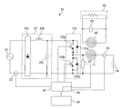
- FIG. 6 is a diagram showing a circuit configuration of a drive circuit and a power receiving device of an induction heating cooker according to Embodiment 4 of the present invention.
- the drive circuit 50 according to the fourth embodiment includes output voltage detection means 27 that detects the output voltage of the inverter circuit 123.
- the output voltage detection means 27 is composed of, for example, a voltage sensor, detects the output voltage of the inverter circuit 123, and outputs a voltage signal corresponding to the output voltage value to the control unit 45.
- the load determination unit 46 detects the coil current from the current detection signal of the coil current detection unit 25 and detects the output voltage from the voltage detection signal of the output voltage detection unit 27. The load determination unit 46 calculates the load impedance based on the coil current and the output voltage. Then, the load determination unit 46 performs load determination based on whether or not the impedance has resonance characteristics when the drive frequency of the inverter circuit 123 is changed.
- the subsequent load determination operation is the same as any of the load determination operations in the first to third embodiments described above.
- the load determination unit 46 determines that the load on the top 4 is the power receiving device 200 when the calculated impedance increases as the drive frequency of the inverter circuit 123 decreases. Further, for example, the load determination unit 46 determines that the load on the top 4 is the power receiving device 200 when the calculated impedance decreases as the drive frequency of the inverter circuit 123 increases. Further, for example, when the load determination unit 46 changes the driving frequency of the inverter circuit 123 within a preset range, when the calculated impedance changes more than a preset change amount, the load on the top 4 is connected to the power receiving device. 200 is determined.
- the load determination unit 46 calculates the impedance based on the coil current and the output voltage, and the impedance when the drive frequency of the inverter circuit 123 is changed has resonance characteristics. In this case, it is determined that the load is the power receiving device 200. That is, since load determination is performed based on the presence or absence of resonance characteristics that are not present in the heated object 5 such as a pan, the accuracy of load determination can be improved. Therefore, appropriate power can be supplied to the power receiving device 200. In addition, it is possible to easily and reliably determine whether the load is the object to be heated 5 to be induction-heated or the power receiving device 200 to be contactlessly fed using the resonance characteristics of impedance.
- the impedance is calculated based on the coil current and the output voltage, for example, even when the voltage fluctuation of the AC power source 21 occurs and the output voltage of the inverter circuit 123 fluctuates, a change in the impedance of the load is accurately detected. It becomes possible to do. Therefore, more accurate determination can be made.
- Embodiment 5 FIG.
- the configuration and operation of the induction heating cooker 100 according to the fifth embodiment will be described focusing on differences from the first to third embodiments.
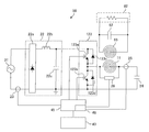
- FIG. 7 is a diagram showing a circuit configuration of a drive circuit and a power receiving device of an induction heating cooker according to Embodiment 5 of the present invention.
- the drive circuit 50 according to the fifth embodiment includes coil voltage detection means 26 that detects a coil voltage applied to the first induction heating coil 11.
- the coil voltage detection means 26 is constituted by, for example, a voltage sensor, detects a voltage applied to the first induction heating coil 11, and outputs a voltage signal corresponding to the coil voltage value to the control unit 45.
- the load determination unit 46 detects the coil current from the current detection signal of the coil current detection unit 25 and detects the coil voltage from the voltage detection signal of the coil voltage detection unit 26. The load determination unit 46 calculates the impedance of the load based on the coil current and the coil voltage. Then, the load determination unit 46 performs load determination based on whether or not the impedance has resonance characteristics when the drive frequency of the inverter circuit 123 is changed.
- the subsequent load determination operation is the same as any of the load determination operations in the first to fourth embodiments described above.
- the load determination unit 46 determines that the load on the top 4 is the power receiving device 200 when the calculated impedance increases as the drive frequency of the inverter circuit 123 decreases. Further, for example, the load determination unit 46 determines that the load on the top 4 is the power receiving device 200 when the calculated impedance decreases as the drive frequency of the inverter circuit 123 increases. Further, for example, when the load determination unit 46 changes the driving frequency of the inverter circuit 123 within a preset range, when the calculated impedance changes more than a preset change amount, the load on the top 4 is connected to the power receiving device. 200 is determined.
- the load determination unit 46 calculates the impedance based on the coil current and the coil voltage, and the impedance when the drive frequency of the inverter circuit 123 is changed has resonance characteristics. In this case, it is determined that the load is the power receiving device 200. That is, since load determination is performed based on the presence or absence of resonance characteristics that are not present in the heated object 5 such as a pan, the accuracy of load determination can be improved. Therefore, appropriate power can be supplied to the power receiving device 200. In addition, it is possible to easily and reliably determine whether the load is the object to be heated 5 to be induction-heated or the power receiving device 200 to be contactlessly fed using the resonance characteristics of impedance.
- the impedance is calculated based on the coil current and the coil voltage, for example, even when the voltage fluctuation of the AC power source 21 occurs and the output voltage of the inverter circuit 123 fluctuates, a change in the impedance of the load is accurately detected. It becomes possible to do. Therefore, more accurate determination can be made. Furthermore, since the resonance characteristics of the power reception coil 65 and the power reception side resonance capacitor 62 of the power reception device 200 can be directly detected without being affected by the resonance characteristics of the first induction heating coil 11 and the power transmission side resonance capacitor 24, more accurate. Judgment can be made.
- Embodiment 6 FIG.
- the configuration and operation of the induction heating cooker 100 according to the sixth embodiment will be described focusing on differences from the first to fifth embodiments.
- FIG. 8 is a diagram showing an induction heating coil of the induction heating cooker according to the sixth embodiment of the present invention.
- the first induction heating coil 11 is composed of an inner peripheral coil 11a disposed in the center and outer peripheral coils 11e and 11d disposed around the inner peripheral coil 11a.
- the outer periphery of the first induction heating coil 11 has a substantially circular shape corresponding to the first induction heating port 1.
- the inner peripheral coil 11a is composed of an inner peripheral inner coil 111a and an inner peripheral outer coil 112a that are arranged substantially concentrically.
- the inner circumference inner coil 111a and the inner circumference outer coil 112a have a circular planar shape, and a conductive wire made of any metal (for example, copper, aluminum, etc.) coated with an insulating film is wound in the circumferential direction. It is configured.
- the inner circumference inner coil 111a and the inner circumference outer coil 112a are connected in series and are driven and controlled by one drive circuit 50a. Note that the inner peripheral inner coil 111a and the inner peripheral outer coil 112a may be connected in parallel, or may be driven using independent drive circuits (inverter circuits).
- the outer peripheral coil 11d is composed of an outer peripheral upper coil 111d and an outer peripheral lower coil 112d.
- the outer peripheral coil 11e is composed of an outer peripheral left coil 111e and an outer peripheral right coil 112e.
- the outer periphery upper coil 111d and the outer periphery lower coil 112d are connected in series and are driven and controlled by one drive circuit 50d.
- the outer peripheral left coil 111e and the outer peripheral right coil 112e are connected in series and are driven and controlled by one drive circuit 50e.
- the outer circumference upper coil 111d, the outer circumference lower coil 112d, the outer circumference left coil 111e, and the outer circumference right coil 112e are substantially aligned with the circular outer shape of the inner circumference coil 11a. It is arranged around.
- Each of the four outer peripheral coils has a substantially 1 ⁇ 4 arc shape (banana shape or pepper shape) planar shape, and a conductive wire made of any metal (for example, copper, aluminum, etc.) coated with an insulating film is connected to each outer periphery. It is configured by winding along a quarter arc shape of the coil.
- each outer peripheral coil is configured to extend substantially along the circular planar shape of the inner peripheral coil 11a in a 1 ⁇ 4 arc-shaped region adjacent to the inner peripheral coil 11a.
- the number of outer peripheral coils is not limited to four.
- the shape of each outer periphery coil is not restricted to this, For example, the structure using multiple circular outer periphery coils may be sufficient.
- Each outer coil may be connected in parallel.
- the outer periphery upper coil 111d and the outer periphery lower coil 112d may be driven using one drive circuit (inverter circuit).
- the drive circuits 50a, 50d, and 50e have the same configuration as the drive circuit 50 of the first embodiment.
- the control unit 45 performs load determination of the load placed above each of the drive circuits 50a, 50d, and 50e.
- the load determination operation is the same as in any of the first to fifth embodiments.
- the load determination unit 46 of the control unit 45 changes the drive frequency of the inverter circuit 123 for each of the drive circuits 50a, 50d, and 50e, and places it on the upper side using the impedance characteristic on the output side of each inverter circuit 123. The load of the load that is being used is judged.
- the control unit 45 controls the drive circuit in which the determination result of the load determination unit 46 is the object to be heated 5 among the drive circuits 50 a, 50 d, and 50 e according to the heating power for induction heating, and induces the object to be heated 5 A heating operation for heating is performed. Thereby, the to-be-heated object 5 arrange
- the control unit 45 controls the drive circuit in which the determination result of the load determination unit 46 is the power receiving device 200 among the drive circuits 50a, 50d, and 50e according to the power transmitted to the power receiving coil 65. Power transmission operation for supplying power to 65 is performed.
- the load determination unit 46 may determine whether or not there is a load. In this case, the control unit 45 stops the operation of the drive circuit determined to be no load.
- the control unit 45 controls each drive circuit so that the total value of the power for inductively heating the article to be heated 5 and the power transmitted to the power receiving coil 65 is equal to or less than a predetermined power (rated power). Control. For example, it is controlled to 3 kW or less.
- a predetermined power rated power
- Control For example, it is controlled to 3 kW or less.
- the object 5 to be heated such as a heating plate
- the power receiving device 200 is placed above the outer circumference coil 11d
- the outer circumference coil The maximum power of 1.5 kW can be input to 11d, and the remaining power can be input to the object to be heated 5 such as a heating plate at the maximum.
- the inverter circuit 123 having resonance characteristics is caused to perform power transmission operation, and among the plurality of inverter circuits 123, the inverter circuit 123 having no resonance characteristics.
- the heating operation is performed. For this reason, the heating by induction heating and the heating by non-contact electric power transmission can be performed simultaneously with one heating port, and the convenience can be improved. Further, heating by induction heating and heating by non-contact power transmission can be individually controlled.
- Embodiment 7 FIG.
- the configuration and operation of the induction heating cooker 100 according to the seventh embodiment will be described focusing on differences from the first to sixth embodiments.
- the load determination unit 46 performs a load determination operation as in any of the first to fifth embodiments.
- the control unit 45 causes the display unit 41 to display the result of the load determination by the load determination unit 46. Thereby, the user can confirm the result of the load determination by the load determination unit 46.
- the determination result of the load determination unit 46 may be corrected by an operation from the operation unit 40.
- the control unit 45 displays the determination result on the display unit 41 and then an operation for correcting the determination result is input by an input operation from the operation unit 40, induction heating is performed according to the corrected determination result. Perform the operation or power transmission operation.
- the determination result can be corrected by an operation from the user. Therefore, when the load determination result of the load determination unit 46 and the load actually placed on the top plate 4 do not coincide with each other, the power receiving apparatus 200 is heated or the object to be heated 5 is heated. This prevents power transmission operation.
- Embodiment 8 FIG.
- the configuration and operation of the induction heating cooker 100 according to the eighth embodiment will be described focusing on differences from the first to seventh embodiments.
- the control unit 45 stores information (learning data) on the impedance on the output side of the inverter circuit 123 in the memory 48 when the load determination unit 46 performs load determination. In the next load determination operation, the load determination unit 46 sets the amount of change in the drive frequency of the inverter circuit 123 based on the information stored in the memory 48.
- the resonance characteristics (relationship between frequency and impedance) of the power receiving device 200 are stored in the memory 48 in the load determination operation.
- the drive frequency is changed based on information (learning data) stored in the memory 48. For example, in the case of the resonance characteristics shown in FIG. 5, when the drive frequency is changed from a high frequency to a low frequency, the impedance (coil current) is detected only at two points of 50 kHz and 30 kHz, and the power receiving device 200 is present. Determine whether or not. Thereby, the speed of the load determination operation can be increased.
- the impedance value or the coil current value is stored in the memory 48 at a preset frequency interval (for example, every 5 kHz). Then, in the load determination operation after the next time, when the drive frequency of the inverter circuit 123 is changed, the frequency range band in which the previous impedance value or the amount of change in the coil current value is small is skipped. Further, for example, in the load determination operation, the frequency at which the amount of change in impedance (coil current) peaks is stored in the memory 48.
- the drive frequency of the inverter circuit 123 is changed in the load determination operation after the next time, the drive frequency of the inverter circuit 123 is only in a predetermined frequency range including the frequency at which the change amount has peaked in the previous load determination operation. To change.
- the drive frequency of the inverter circuit 123 A normal load determination operation may be performed to generalize within a preset range.
- Embodiment 9 FIG.
- the induction heating cooker 100 that transmits power to the power receiving device 200 and heats the article to be heated 5 has been described.
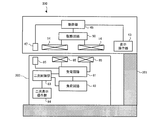
- a non-contact power transmission apparatus 300 that omits the function of heating the article to be heated 5 and only transmits power to the power receiving apparatus 200 will be described.
- FIG. 9 is a block diagram showing configurations of the non-contact power transmission apparatus and the power receiving apparatus according to Embodiment 9 of the present invention.
- the non-contact power transmission device 300 and the power receiving device 200 constitute a non-contact power transmission system.
- the non-contact power transmission device 300 includes a support body 301 configured to support the power receiving device 200 in a high-frequency magnetic field (electromagnetic field) generated from the power supply coil 14.
- the configuration of power reception device 200 is the same as in the first to eighth embodiments.
- the power supply coil 14 of the non-contact power transmission apparatus 300 has a circular planar shape corresponding to the power reception coil 65 of the power reception apparatus 200, and a conductive wire made of an arbitrary metal (for example, copper, aluminum, etc.) coated with an insulating film. It is configured by being wound in the circumferential direction.
- Other configurations of the non-contact power transmission apparatus 300 are the same as those in the first to eighth embodiments.
- the load determination unit 46 of the control unit 45 in the ninth embodiment performs the load determination operation described above. In addition, the control unit 45 in the ninth embodiment performs the above-described power transmission operation.
- the support body 301 of the non-contact power transmission device 300 may be configured to support the power receiving device 200 below the non-contact power transmission device 300.
- this invention is not limited to this, You may support the power receiving apparatus 200 in arbitrary positions with respect to the non-contact electric power transmission apparatus 300. FIG.
- the non-contact power transmission apparatus 300 may be configured not to perform a heating operation. Even in such a configuration, it is possible to supply appropriate power to the power receiving apparatus 200. In addition, since the load determination is performed using the resonance characteristic of the impedance of the power receiving device 200, it can be easily and reliably determined whether or not the power receiving device 200 is used. Therefore, appropriate power can be supplied to the power receiving device 200. Therefore, a highly reliable contactless power transmission system can be obtained.
Landscapes
- Engineering & Computer Science (AREA)
- Power Engineering (AREA)
- Computer Networks & Wireless Communication (AREA)
- Physics & Mathematics (AREA)
- Electromagnetism (AREA)
- Induction Heating Cooking Devices (AREA)
Abstract
Description
しかしながら、誘導加熱すべき被加熱物の材質、形状、大きさ等は様々であり、半導体スイッチの導通時間の変化と入力電流値の変化との関係が電気機器の特性に近い被加熱物が存在する。このため、負荷判別部の判別結果に誤りが発生する場合がある。負荷判別部の判別結果に誤りがある場合、電気機器へ適切な電力を供給することができない、という課題があった。
(構成)
図1は、本発明の実施の形態1に係る誘導加熱調理器を示す分解斜視図である。
図1に示すように、誘導加熱調理器100の上部には、鍋等の被加熱物5が載置される天板4を有している。本実施の形態1に係る誘導加熱調理器100においては、図3等で後述するように、天板4上に受電装置200も載置される。本実施の形態1に係る誘導加熱調理器100は、受電装置200に電力を伝送する非接触電力装置として機能する。
天板4には、被加熱物5を誘導加熱するための加熱口として、第一の誘導加熱口1及び第二の誘導加熱口2を備えている。第一の誘導加熱口1及び第二の誘導加熱口2は、天板4の手前側において、横方向に並設されている。また、本実施の形態1に係る誘導加熱調理器100は、3口目の加熱口として、第三の誘導加熱口3も備えている。第三の誘導加熱口3は、第一の誘導加熱口1及び第二の誘導加熱口2の奥側であって、天板4の横方向のほぼ中央位置に設けられている。
第一の誘導加熱口1、第二の誘導加熱口2及び第三の誘導加熱口3のそれぞれの下方には、加熱口に載置された被加熱物を加熱する第一の誘導加熱コイル11、第二の誘導加熱コイル12及び第三の誘導加熱コイル13が設けられている。
また、操作部40の近傍には、報知手段として、各誘導加熱コイルの動作状態、操作部40からの入力及び操作内容等を表示する表示部41が設けられている。なお、本実施の形態1では、誘導加熱コイル毎に表示部41を分けて、表示部41a、表示部41b及び表示部41cとしている。
なお、操作部40と表示部41とは、これらを一体に構成した表示操作部43としても良い。表示操作部43は、例えば、LCDの上面にタッチスイッチを配置したタッチパネル等によって構成される。
第一の誘導加熱コイル11は、略同心円状に配置された複数のコイルで構成されている。例えば、第一の誘導加熱コイル11は、略同心円状に配置された4重のコイル11-1~11-4で構成されている。これらコイル11-1~11-4は、ひと繋ぎに接続されている。また、これらコイル11-1~11-4は、絶縁皮膜された任意の金属(例えば銅、アルミ等)からなる導電線を巻き付けることにより構成される。
駆動回路50により高周波電力が、第一の誘導加熱コイル11、第二の誘導加熱コイル12及び第三の誘導加熱コイル13に供給されることで、各誘導加熱コイルからは高周波磁界が発生する。なお、駆動回路50の詳細構成については、後述する。
制御部45が専用のハードウェアである場合、制御部45は、例えば、単一回路、複合回路、ASIC(application specific integrated circuit)、FPGA(field-programmable gate array)、又はこれらを組み合わせたものが該当する。制御部45が実現する各機能部のそれぞれを、個別のハードウェアで実現しても良いし、各機能部を一つのハードウェアで実現しても良い。
制御部45がCPUの場合、制御部45が実行する各機能は、ソフトウェア、ファームウェア、又はソフトウェアとファームウェアとの組み合わせにより実現される。ソフトウェアやファームウェアはプログラムとして記述され、メモリ48に格納される。CPUは、メモリ48に格納されたプログラムを読み出して実行することにより、制御部45の各機能を実現する。ここで、メモリ48は、例えば、RAM、ROM、フラッシュメモリ、EPROM、EEPROM等の、不揮発性又は揮発性の半導体メモリである。
なお、制御部45の機能の一部を専用のハードウェアで実現し、一部をソフトウェア又はファームウェアで実現するようにしても良い。
この受電装置200は、誘導加熱調理器100の天板4の上に載置され、誘導加熱調理器100から非接触で電力を受電する。即ち、誘導加熱調理器100の天板4の下の第一の誘導加熱コイル11に、駆動回路50により高周波電力が供給されることで、第一の誘導加熱コイル11からは高周波磁界が発生する。この高周波磁界を受電装置200の中に設けられた受電コイル65で受け、非接触で受電装置200への給電を行う。
この際、受電装置200の二次制御部83は、負荷回路82がヒータ負荷の場合、受電コイル65で受けた電力を交流のまま負荷回路82に供給するように、受電回路81を制御する。
また例えば、二次制御部83は、負荷回路82がモータ負荷の場合、受電コイル65で受けた電力を整流及び平滑し、インバータ回路等で任意の交流に変換して負荷回路82に供給するように、受電回路81を制御する。つまり、負荷回路82がモータ負荷の場合、負荷回路82を可変速駆動する。なお、ヒータ負荷に整流及び平滑して直流を印加しても良い。また、モータ負荷を一定速で駆動しても良いことは言うまでもない。
また、図3に図示はしていないが、第一の誘導加熱コイル11の下部に磁性体としてフェライトを配置する。フェライトの形状は、例えば平板形状である。第一の誘導加熱コイル11を構成するコイル間に挿入される突起を平板状のフェライト上面に設け、フェライトの縦断面形状を凸型、F型又はE型等にしても良い。また、図3に図示はしていないが、受電コイル65の上部に磁性体としてフェライトを配置する。フェライトの形状は、例えば平板形状である。受電コイル65を構成するコイル間に挿入される突起を平板状のフェライト下面に設け、フェライトの縦断面形状を凸型、F型又はE型等にしても良い。
入力電流検出手段23は、例えば電流センサで構成され、交流電源(商用電源)21から直流電源回路22へ入力される電流を検出し、入力電流値に相当する電圧信号を制御部45へ出力する。
受電側共振コンデンサ62は、受電コイル65に並列接続されており、この共振回路は受電コイル65のインダクタンス及び受電側共振コンデンサ62の容量等に応じた共振周波数を有する。なお、受電コイル65のインダクタンスは第一の誘導加熱コイル11が磁気結合した際の共振回路で共振周波数が定まる。
また、天板4は、本発明の「支持体」に相当する。
また、制御部45は、本発明の「制御装置」に相当する。
また、負荷判定部46は、本発明の「制御装置」に含まれる。
また、表示部41は、本発明の「報知手段」に相当する。
また、メモリ48は、本発明の「記憶手段」に相当する。
ここで、共振回路を有する受電装置200と、鍋などの被加熱物5のインピーダンス特性について説明する。
図5においては、横軸がインバータ回路123の駆動周波数を示し、縦軸がインバータ回路123の出力側のインピーダンス(送電側から見たインピーダンス)を示す。
図5に示すように、共振回路を有する受電装置200が負荷である場合、共振回路の共振周波数にてインピーダンスが最大となり、共振周波数より低い周波数及び共振周波数より高い周波数にてインピーダンスが減少する。
即ち、共振周波数よりも高い範囲において、負荷が受電装置200である場合のインピーダンスは、駆動周波数の減少に伴いインピーダンスが増加する共振特性を有する。
また、共振周波数よりも低い範囲において、負荷が受電装置200である場合のインピーダンスは、駆動周波数の増加に伴いインピーダンスが増加する共振特性を有する。
更に、共振周波数を含む周波数範囲において、負荷が受電装置200である場合のインピーダンスは、駆動周波数の変化に伴いインピーダンスの増加と減少とを含む共振特性を有する。
次に、上述したインピーダンス特性を用いて負荷判定を行う負荷判定動作について説明する。
負荷判定動作において、制御部45は、負荷判定用の特定の駆動信号でインバータ回路123を駆動する。負荷判定部46は、コイル電流検出手段25の電流検知信号からコイル電流を検出する。
次に、制御部45は、インバータ回路123の駆動周波数を、高い周波数から低い周波数へ減少させる。負荷判定部46は、コイル電流検出手段25の電流検知信号からコイル電流を逐次検出する。
このため、本実施の形態1における負荷判定部46は、インバータ回路123の駆動周波数を変化させた際の、コイル電流が共振特性を有するか否かにより負荷判定を行う。
一方、インバータ回路123の駆動周波数の減少に伴い、コイル電流検出手段25の電流検知信号が増加(インピーダンスが減少)する場合、天板4上の負荷が被加熱物5であると判定する。
例えば、第一の誘導加熱コイル11と送電側共振コンデンサ24との共振周波数が18kHzである場合、負荷判定動作で変化させる駆動周波数を20kHz以上とする。
これにより、インバータ回路123に進相電流が流れて、インバータ回路123が破壊するのを防ぐことができる。
例えば、繰り返しによる学習機能(後述)により、受電装置200の共振回路の共振周波数が28kHz程度であると想定されている場合には、負荷判定動作において、インバータ回路123の駆動周波数を50kHzから20kHzまで減少させても良い。これにより、負荷判定動作の時間を短くすることができる。
負荷判定部46の判定結果が受電装置200である場合、制御部45は、受電装置200に電力を伝送する電力伝送動作を行う。
すなわち、制御部45は、受電コイル65へ送電する電力に応じて駆動回路50を制御して、第一の誘導加熱コイル11に高周波電力を供給する。これにより、第一の誘導加熱コイル11から供給された高周波電力は、受電装置200に配置された受電コイル65により受電される。受電された電力は、受電回路81から負荷回路82へ供給され、負荷回路82が駆動する。
負荷判定部46の判定結果が被加熱物5である場合、制御部45は、被加熱物5を誘導加熱する加熱動作を行う。
すなわち、制御部45は、誘導加熱させる火力に応じて駆動回路50を制御して、第一の誘導加熱コイル11に高周波電力を供給する加熱動作を行う。これにより、天板4上に配置された被加熱物5が誘導加熱される。
このため、受電装置200へ適切な電力を供給することができる。また、インピーダンスの共振特性を利用して、負荷が誘導加熱すべき被加熱物5か、非接触給電すべき受電装置200か否か容易にかつ確実に判定することができる。
本実施の形態2においては、インバータ回路123の駆動周波数を、低い周波数から高い周波数へ増加させる負荷判定動作について説明する。
以下、本実施の形態2における負荷判定動作を、上記実施の形態1との相違点を中心に説明する。
制御部45内に設けられた負荷判定部46は、操作部40からの動作開始信号に基づいて、負荷判定動作を開始する。
負荷判定動作において、制御部45は、負荷判定用の特定の駆動信号でインバータ回路123を駆動する。負荷判定部46は、コイル電流検出手段25の電流検知信号からコイル電流を検出する。
次に、制御部45は、インバータ回路123の駆動周波数を、低い周波数から高い周波数へ増加させる。負荷判定部46は、コイル電流検出手段25の電流検知信号からコイル電流を逐次検出する。
すなわち、負荷判定部46は、インバータ回路123の駆動周波数の増加に伴い、コイル電流検出手段25の電流検知信号が増加(インピーダンスが減少)する場合、天板4上の負荷が受電装置200であると判定する。
一方、インバータ回路123の駆動周波数の増加に伴い、コイル電流検出手段25の電流検知信号が減少(インピーダンスが増加)する場合、天板4上の負荷が被加熱物5であると判定する。
例えば、第一の誘導加熱コイル11と送電側共振コンデンサ24との共振周波数が18kHzである場合、負荷判定動作で変化させる駆動周波数を20kHz以上とする。
これにより、インバータ回路123に進相電流が流れて、インバータ回路123が破壊するのを防ぐことができる。
したがって、受電装置200へ適切な電力を供給することができる。また、インピーダンスの共振特性を利用して、負荷が誘導加熱すべき被加熱物5か、非接触給電すべき受電装置200か否かを容易にかつ確実に判定することができる。
上記実施の形態1では、駆動周波数を減少させた際のインピーダンスの増加の有無により負荷判定を行い、本実施の形態2では駆動周波数を増加させた際のインピーダンスの減少の有無により負荷判定を行ったが、本発明はこれに限定されない。
例えば、負荷判定部46は、インバータ回路123の駆動周波数を予め設定した範囲で変化させた際、インピーダンスの増加と減少とを含む共振特性を有する場合、負荷が受電装置200であると判定してもよい。
例えば、インバータ回路123の駆動周波数を予め設定した範囲で増加又は減少させた際、コイル電流が減少から増加に転じた場合(インピーダンスが増加から減少)、天板4上の負荷が受電装置200であると判定する。
このような動作においても、鍋などの被加熱物5には無い共振特性の有無によって負荷判定を行うことができ、負荷判定の精度を向上させることができる。
本実施の形態3においては、インバータ回路123の駆動周波数を予め設定した範囲で変化させた際、インピーダンスの変化量によって負荷を判定する負荷判定動作について説明する。
以下、本実施の形態3における負荷判定動作を、上記実施の形態1との相違点を中心に説明する。
制御部45内に設けられた負荷判定部46は、操作部40からの動作開始信号に基づいて、負荷判定動作を開始する。
負荷判定動作において、制御部45は、負荷判定用の特定の駆動信号でインバータ回路123を駆動する。負荷判定部46は、コイル電流検出手段25の電流検知信号からコイル電流を検出する。
次に、制御部45は、インバータ回路123の駆動周波数を予め設定した範囲で変化させる。この範囲は、例えば、20kHz以上100kHz未満の範囲に含まれる任意の周波数範囲に設定して良い。
負荷判定部46は、コイル電流検出手段25の電流検知信号からコイル電流を逐次検出する。
例えば、図5に示した例においては、インバータ回路123の駆動周波数を50kHzから30kHzまで変化させると、鍋などの被加熱物5の場合はインピーダンスが約30%減少するが、受電装置200の場合はインピーダンスが約400%増加し、変化量に明らかに違いがある。
本実施の形態3における負荷判定部46は、このインピーダンスの変化量(コイル電流の変化量)を利用して負荷判定する。
すなわち、負荷判定部46は、インバータ回路123の駆動周波数を予め設定した範囲で変化させた際、コイル電流検出手段25の電流検知信号が予め設定された変化量以上変化する場合、天板4上の負荷が受電装置200であると判定する。
一方、コイル電流検出手段25の電流検知信号が予め設定された変化量以上変化しない場合、天板4上の負荷が被加熱物5であると判定する。
例えば、第一の誘導加熱コイル11と送電側共振コンデンサ24との共振周波数が18kHzである場合、負荷判定動作で変化させる駆動周波数を20kHz以上とする。
これにより、インバータ回路123に進相電流が流れて、インバータ回路123が破壊するのを防ぐことができる。
したがって、受電装置200へ適切な電力を供給することができる。また、インピーダンスの共振特性を利用して、負荷が誘導加熱すべき被加熱物5か、非接触給電すべき受電装置200か否かを容易にかつ確実に判定することができる。
以下、本実施の形態4における誘導加熱調理器100の構成及び動作を、上記実施の形態1~3との相違点を中心に説明する。
図6に示すように、本実施の形態4における駆動回路50は、インバータ回路123の出力電圧を検出する出力電圧検出手段27を備える。出力電圧検出手段27は、例えば電圧センサで構成され、インバータ回路123の出力電圧を検出し、出力電圧値に相当する電圧信号を制御部45へ出力する。
負荷判定動作において、負荷判定部46は、コイル電流検出手段25の電流検知信号からコイル電流を検出し、出力電圧検出手段27の電圧検知信号から出力電圧を検出する。負荷判定部46は、コイル電流と出力電圧とに基づき負荷のインピーダンスを算出する。
そして、負荷判定部46は、インバータ回路123の駆動周波数を変化させた際の、インピーダンスが共振特性を有するか否かにより負荷判定を行う。
例えば、負荷判定部46は、インバータ回路123の駆動周波数の減少に伴い、算出したインピーダンスが増加する場合、天板4上の負荷が受電装置200であると判定する。
また例えば、負荷判定部46は、インバータ回路123の駆動周波数の増加に伴い、算出したインピーダンスが減少する場合、天板4上の負荷が受電装置200であると判定する。
また例えば、負荷判定部46は、インバータ回路123の駆動周波数を予め設定した範囲で変化させた際、算出したインピーダンスが予め設定された変化量以上変化する場合、天板4上の負荷が受電装置200であると判定する。
さらに、コイル電流と出力電圧とに基づきインピーダンスを算出するので、例えば交流電源21の電圧変動が生じてインバータ回路123の出力電圧が変動した場合であっても、負荷のインピーダンスの変化を精度良く検知することが可能となる。よって、より正確な判定をすることができる。
以下、本実施の形態5における誘導加熱調理器100の構成及び動作を、上記実施の形態1~3との相違点を中心に説明する。
図7に示すように、本実施の形態5における駆動回路50は、第一の誘導加熱コイル11に印加されるコイル電圧を検出するコイル電圧検出手段26を備える。コイル電圧検出手段26は、例えば電圧センサで構成され、第一の誘導加熱コイル11に印加される電圧を検出し、コイル電圧値に相当する電圧信号を制御部45へ出力する。
負荷判定動作において、負荷判定部46は、コイル電流検出手段25の電流検知信号からコイル電流を検出し、コイル電圧検出手段26の電圧検知信号からコイル電圧を検出する。負荷判定部46は、コイル電流とコイル電圧とに基づき負荷のインピーダンスを算出する。
そして、負荷判定部46は、インバータ回路123の駆動周波数を変化させた際の、インピーダンスが共振特性を有するか否かにより負荷判定を行う。
例えば、負荷判定部46は、インバータ回路123の駆動周波数の減少に伴い、算出したインピーダンスが増加する場合、天板4上の負荷が受電装置200であると判定する。
また例えば、負荷判定部46は、インバータ回路123の駆動周波数の増加に伴い、算出したインピーダンスが減少する場合、天板4上の負荷が受電装置200であると判定する。
また例えば、負荷判定部46は、インバータ回路123の駆動周波数を予め設定した範囲で変化させた際、算出したインピーダンスが予め設定された変化量以上変化する場合、天板4上の負荷が受電装置200であると判定する。
また、コイル電流とコイル電圧とに基づきインピーダンスを算出するので、例えば交流電源21の電圧変動が生じてインバータ回路123の出力電圧が変動した場合であっても、負荷のインピーダンスの変化を精度良く検知することが可能となる。よって、より正確な判定をすることができる。
さらに、受電装置200の受電コイル65と受電側共振コンデンサ62の共振特性が、第一の誘導加熱コイル11と送電側共振コンデンサ24の共振特性の影響を受けずに直接検知できるため、更に正確な判定をすることができる。
以下、本実施の形態6における誘導加熱調理器100の構成及び動作を、上記実施の形態1~5との相違点を中心に説明する。
図8において、第一の誘導加熱コイル11は、中央に配置された内周コイル11aと、内周コイル11aの周囲に配置された外周コイル11e、11dとで構成されている。第一の誘導加熱コイル11の外周は、第一の誘導加熱口1に対応した略円形状である。
4つの各外周コイルは、略1/4円弧状(バナナ状または胡瓜状)の平面形状を有しており、絶縁皮膜された任意の金属(例えば銅、アルミなど)からなる導電線を各外周コイルの1/4円弧状の形状に沿って巻きつけることで構成される。すなわち、各外周コイルは、内周コイル11aに隣接する1/4円弧状領域において、内周コイル11aの円形の平面形状に実質的に沿って延びるように構成されている。なお、各外周コイルの数は4つに限定されるものではない。また、各外周コイルの形状もこれに限るものではなく、例えば円形の外周コイルを複数用いた構成でも良い。なお、各外周コイルはそれぞれ並列接続しても良い。また、外周上コイル111dと外周下コイル112dを一つの駆動回路(インバータ回路)を用いて駆動しても良い。
なお、駆動回路50a、50d、50eは、上記実施の形態1の駆動回路50と同じ構成である。
第一の誘導加熱口1上に、被加熱物5と受電装置200とが載置された場合の動作を説明する。
制御部45の負荷判定部46は、駆動回路50a、50d、50eのそれぞれについて、インバータ回路123の駆動周波数を変化させ、それぞれのインバータ回路123の出力側のインピーダンス特性を用いて、上方に載置されている負荷の負荷判定を行う。
一方、制御部45は、駆動回路50a、50d、50eのうち、負荷判定部46の判定結果が受電装置200である駆動回路を、受電コイル65へ送電する電力に応じて制御して、受電コイル65へ電力を供給する電力伝送動作を行う。
なお、負荷判定部46により、負荷の有無を判定するようにしても良い。この場合、制御部45は、無負荷であると判定した駆動回路の動作を停止させる。
例えば、内周コイル11a、及び外周コイル11eの上方に、加熱プレートなどの磁性体である被加熱物5が載置され、外周コイル11dの上方に受電装置200が載置された場合、外周コイル11dには最大1.5kWの電力が投入可能で、加熱プレートなどの被加熱物5には残りの電力を最大として電力の投入が可能である。
このため、1つの加熱口で、誘導加熱による加熱と非接触電力伝送による加熱とを同時に行うことができ、利便性を向上することができる。また、誘導加熱による加熱と非接触電力伝送による加熱とを個別に制御することができる。
以下、本実施の形態7における誘導加熱調理器100の構成及び動作を、上記実施の形態1~6との相違点を中心に説明する。
負荷判定部46は、上記実施の形態1~5の何れかと同様に、負荷判定動作を行う。
制御部45は、負荷判定部46による負荷判定の結果を、表示部41に表示させる。
これにより、使用者が、負荷判定部46の負荷判定の結果を確認することが可能となる。
これにより、使用者からの操作により判定結果を修正することが可能となる。よって、負荷判定部46の負荷判定の結果と、実際に天板4上に載置した負荷とが一致していない場合に、受電装置200に対して加熱動作させたり、被加熱物5に対して電力伝送動作をさせることがなくなる。
以下、本実施の形態8における誘導加熱調理器100の構成及び動作を、上記実施の形態1~7との相違点を中心に説明する。
また例えば、負荷判定動作において、インピーダンス(コイル電流)の変化量がピークとなる周波数をメモリ48に記憶させる。そして、次回以降の負荷判定動作において、インバータ回路123の駆動周波数を変化させる際、前回の負荷判定動作において、変化量がピークとなった周波数を含む所定の周波数範囲のみ、インバータ回路123の駆動周波数を変化させる。
上記実施の形態1~8においては、受電装置200への電力の伝送と被加熱物5の加熱とを行う誘導加熱調理器100について説明した。本実施の形態9では、被加熱物5の加熱を行う機能を省略し、受電装置200への電力の伝送のみを行う非接触電力伝送装置300について説明する。
図9において、非接触電力伝送装置300と、受電装置200とにより非接触電力伝送システムを構成している。
受電装置200の構成は、上記実施の形態1~8と同様である。
非接触電力伝送装置300の給電コイル14は、受電装置200の受電コイル65に対応した例えば円形の平面形状を有し、絶縁被膜された任意の金属(例えば銅、アルミなど)からなる導電線が円周方向に巻回されることにより構成されている。非接触電力伝送装置300のその他の構成は、上記実施の形態1~8と同様である。
本実施の形態9における制御部45の負荷判定部46は、上述した負荷判定動作を行う。また、本実施の形態9における制御部45は、上述した電力伝送動作を行う。
また、受電装置200のインピーダンスの共振特性を利用して、負荷判定を行うので受電装置200か否かを容易にかつ確実に判定することができる。よって、受電装置200へ適切な電力を供給することができる。したがって、信頼性の高い非接触電力伝送システムを得ることができる。
Claims (15)
- 共振回路を有する受電装置に電力を伝送するための非接触電力伝送装置であって、
高周波電流が供給されることによって高周波磁場を発生するコイルと、
前記高周波磁場内に前記受電装置を支持するように構成された支持体と、
前記コイルに前記高周波電流を供給するインバータ回路と、
前記インバータ回路の駆動を制御する制御装置と、
を備え、
前記制御装置は、
前記インバータ回路の駆動周波数を変化させた際の、前記インバータ回路の出力側のインピーダンスが共振特性を有する場合、前記受電装置に電力を伝送する電力伝送動作を行うように構成された
非接触電力伝送装置。 - 前記共振特性は、
前記インバータ回路の駆動周波数の減少に伴い、前記インピーダンスが増加する特性である
請求項1に記載の非接触電力伝送装置。 - 前記共振特性は、
前記インバータ回路の駆動周波数の増加に伴い、前記インピーダンスが減少する特性である
請求項1に記載の非接触電力伝送装置。 - 前記共振特性は、
前記インバータ回路の駆動周波数を予め設定した範囲で変化させた際、前記インピーダンスの増加と減少とを含む特性である
請求項1に記載の非接触電力伝送装置。 - 前記共振特性は、
前記インバータ回路の駆動周波数を予め設定した範囲で変化させた際、前記インピーダンスが予め設定された変化量以上変化する特性である
請求項1に記載の非接触電力伝送装置。 - 前記コイルと共に共振回路を形成する送電側共振コンデンサを備え、
前記制御装置は、
前記インバータ回路の駆動周波数を変化させる際、前記駆動周波数を前記コイルと前記送電側共振コンデンサとの共振周波数より大きくする
請求項1~5の何れか一項に記載の非接触電力伝送装置。 - 前記インバータ回路の駆動周波数を変化させる範囲は、20kHz以上100kHz未満の範囲に含まれる
請求項1~6の何れか一項に記載の非接触電力伝送装置。 - 前記コイルに流れるコイル電流を検出するコイル電流検出手段を備え、
前記制御装置は、
前記インバータ回路の駆動周波数を変化させた際の、前記コイル電流が共振特性を有する場合、前記受電装置に電力を伝送する電力伝送動作を行う
請求項1~7の何れか一項に記載の非接触電力伝送装置。 - 前記コイルに流れるコイル電流を検出するコイル電流検出手段と、
前記インバータ回路の出力電圧を検出する出力電圧検出手段と、を備え、
前記制御装置は、
前記コイル電流と前記出力電圧とに基づき前記インピーダンスを求め、
前記インバータ回路の駆動周波数を変化させた際の、前記インピーダンスが共振特性を有する場合、前記受電装置に電力を伝送する電力伝送動作を行う
請求項1~7の何れか一項に記載の非接触電力伝送装置。 - 前記コイルに流れるコイル電流を検出するコイル電流検出手段と、
前記コイルに印加されるコイル電圧を検出するコイル電圧検出手段と、を備え、
前記制御装置は、
前記コイル電流と前記コイル電圧とに基づき前記インピーダンスを求め、
前記インバータ回路の駆動周波数を変化させた際の、前記インピーダンスが共振特性を有する場合、前記受電装置に電力を伝送する電力伝送動作を行う
請求項1~7の何れか一項に記載の非接触電力伝送装置。 - 報知手段を備え、
前記制御装置は、
前記インバータ回路の出力側のインピーダンスが共振特性を有する場合、負荷が前記受電装置である旨を前記報知手段により報知させる
請求項1~10の何れか一項に記載の非接触電力伝送装置。 - 前記インバータ回路の駆動周波数を変化させた際の、前記インバータ回路の出力側のインピーダンスに関する情報を記憶する記憶手段を備え、
前記制御装置は、
前記記憶手段に記憶された情報に基づき、前記インバータ回路の駆動周波数の変化量を設定する
請求項1~11の何れか一項に記載の非接触電力伝送装置。 - 請求項1~12の何れか一項に記載の非接触電力伝送装置と、
前記非接触電力伝送装置と着脱可能に支持される受電装置と、
を備え、
前記受電装置は、
前記コイルの前記高周波磁場内に配置されると、前記コイルから電力を受電する受電コイルと、
前記受電コイルと共に共振回路を形成する受電側共振コンデンサと、
を備えた非接触電力伝送システム。 - 共振回路を有する受電装置への電力の伝送と被加熱物の加熱とを行う誘導加熱調理器であって、
前記受電装置又は前記被加熱物が載置される天板と、
前記天板の下に配置されたコイルと、
前記コイルに高周波電流を供給するインバータ回路と、
前記インバータ回路の駆動を制御して、前記受電装置に電力を伝送する電力伝送動作と、前記被加熱物を誘導加熱する加熱動作と、を切り換えるように構成された制御装置と、
を備え、
前記制御装置は、
前記インバータ回路の駆動周波数を変化させた際の、前記インバータ回路の出力側のインピーダンスが共振特性を有する場合、前記電力伝送動作を行い、
前記インバータ回路の駆動周波数を変化させた際の、前記インバータ回路の出力側のインピーダンスが共振特性を有しない場合、前記加熱動作を行う
誘導加熱調理器。 - 前記天板は、前記被加熱物の載置位置を示す加熱口が形成され、
前記コイルは、一つの前記加熱口に対して複数設けられ、
前記インバータ回路は、複数の前記コイルにそれぞれ設けられ、
前記制御装置は、
複数の前記インバータ回路のそれぞれについて、前記インバータ回路の駆動周波数を変化させた際の、前記インバータ回路の出力側のインピーダンスが、共振特性を有するか否かを判定し、
複数の前記インバータ回路のうち、前記共振特性を有する前記インバータ回路を、前記電力伝送動作させ、
複数の前記インバータ回路のうち、前記共振特性を有しない前記インバータ回路を、前記加熱動作させる
請求項14に記載の誘導加熱調理器。
Priority Applications (6)
| Application Number | Priority Date | Filing Date | Title |
|---|---|---|---|
| PCT/JP2016/069532 WO2018003092A1 (ja) | 2016-06-30 | 2016-06-30 | 非接触電力伝送装置、非接触電力伝送システム、及び誘導加熱調理器 |
| CN201680087099.0A CN109417311B (zh) | 2016-06-30 | 2016-06-30 | 非接触电力传送系统以及感应加热烹调器 |
| GB1818921.7A GB2565930B (en) | 2016-06-30 | 2016-06-30 | Wireless power transmission system and induction heating cooker |
| US16/095,631 US10734845B2 (en) | 2016-06-30 | 2016-06-30 | Wireless power transmission system and induction heating cooker |
| DE112016007024.1T DE112016007024T5 (de) | 2016-06-30 | 2016-06-30 | Drahtlose leistungsübertragungs-einrichtung, drahtloses leistungsübertragungs-system und induktionsherd |
| JP2018524686A JP6559348B2 (ja) | 2016-06-30 | 2016-06-30 | 非接触電力伝送システム及び誘導加熱調理器 |
Applications Claiming Priority (1)
| Application Number | Priority Date | Filing Date | Title |
|---|---|---|---|
| PCT/JP2016/069532 WO2018003092A1 (ja) | 2016-06-30 | 2016-06-30 | 非接触電力伝送装置、非接触電力伝送システム、及び誘導加熱調理器 |
Publications (1)
| Publication Number | Publication Date |
|---|---|
| WO2018003092A1 true WO2018003092A1 (ja) | 2018-01-04 |
Family
ID=60786205
Family Applications (1)
| Application Number | Title | Priority Date | Filing Date |
|---|---|---|---|
| PCT/JP2016/069532 Ceased WO2018003092A1 (ja) | 2016-06-30 | 2016-06-30 | 非接触電力伝送装置、非接触電力伝送システム、及び誘導加熱調理器 |
Country Status (6)
| Country | Link |
|---|---|
| US (1) | US10734845B2 (ja) |
| JP (1) | JP6559348B2 (ja) |
| CN (1) | CN109417311B (ja) |
| DE (1) | DE112016007024T5 (ja) |
| GB (1) | GB2565930B (ja) |
| WO (1) | WO2018003092A1 (ja) |
Cited By (2)
| Publication number | Priority date | Publication date | Assignee | Title |
|---|---|---|---|---|
| WO2021194173A1 (ko) * | 2020-03-27 | 2021-09-30 | 엘지전자 주식회사 | 유도 가열 방식의 쿡탑 |
| JP2022542125A (ja) * | 2019-08-19 | 2022-09-29 | ▲広▼▲東▼美的白色家▲電▼技▲術▼▲創▼新中心有限公司 | 検出回路、電気器具及び制御方法 |
Families Citing this family (11)
| Publication number | Priority date | Publication date | Assignee | Title |
|---|---|---|---|---|
| AU2015411672B2 (en) * | 2015-10-16 | 2019-02-07 | Mitsubishi Electric Corporation | Heating cooker system, inductive heating cooker, and electric apparatus |
| US11483903B2 (en) * | 2018-05-18 | 2022-10-25 | Hatco Corporation | Multi-coil induction warming system |
| US11582837B2 (en) | 2018-05-18 | 2023-02-14 | Hateo Corporation | Temperature-regulating appliance with removable base |
| US11609121B2 (en) | 2018-05-18 | 2023-03-21 | Hatco Corporation | Sensor and control systems for food preparation |
| CN112394243B (zh) * | 2019-08-19 | 2024-11-08 | 广东美的白色家电技术创新中心有限公司 | 检测模组及电器设备 |
| KR102835207B1 (ko) * | 2020-02-27 | 2025-07-16 | 엘지전자 주식회사 | 유도 가열 구현 가능한 무선 전력 전송 장치 및 그의 제어 방법 |
| KR102822543B1 (ko) * | 2020-02-27 | 2025-06-18 | 엘지전자 주식회사 | 유도 가열 구현 가능한 무선 전력 전송 장치 및 그의 제어 방법 |
| KR102828703B1 (ko) * | 2020-02-27 | 2025-07-02 | 엘지전자 주식회사 | 유도 가열 구현 가능한 무선 전력 전송 장치 및 그의 제어 방법 |
| KR102809808B1 (ko) * | 2020-02-27 | 2025-05-16 | 엘지전자 주식회사 | 유도 가열 구현 가능한 무선 전력 전송 장치 및 그의 제어 방법 |
| EP4213592A4 (en) * | 2020-09-11 | 2023-11-01 | Mitsubishi Electric Corporation | WARMING COOKER AND WARMING COOKER SYSTEM |
| EP4156455A4 (en) * | 2020-11-04 | 2024-03-06 | Samsung Electronics Co., Ltd. | WIRELESS POWER SYSTEM, WIRELESS POWER TRANSMISSION APPARATUS, AND WIRELESS POWER TRANSMISSION APPARATUS CONTROL METHOD |
Citations (4)
| Publication number | Priority date | Publication date | Assignee | Title |
|---|---|---|---|---|
| JP2012070614A (ja) * | 2010-08-25 | 2012-04-05 | Murata Mfg Co Ltd | 送電装置および電力伝送システム |
| WO2013094174A1 (ja) * | 2011-12-20 | 2013-06-27 | パナソニック株式会社 | 非接触給電装置および非接触電力伝送システム |
| JP2013187963A (ja) * | 2012-03-06 | 2013-09-19 | Murata Mfg Co Ltd | 電力伝送システムおよび送電装置 |
| WO2015125263A1 (ja) * | 2014-02-21 | 2015-08-27 | 株式会社日立製作所 | 送電装置、無線電力伝送システム |
Family Cites Families (18)
| Publication number | Priority date | Publication date | Assignee | Title |
|---|---|---|---|---|
| US4151387A (en) * | 1971-04-06 | 1979-04-24 | Environment/One Corporation | Metal base cookware induction heating apparatus having improved power control circuit for insuring safe operation |
| GB1446737A (en) * | 1972-11-15 | 1976-08-18 | Matsushita Electric Industrial Co Ltd | Induction cooking appliances |
| JP2688862B2 (ja) | 1990-07-31 | 1997-12-10 | シャープ株式会社 | 誘導加熱調理器 |
| CN100521484C (zh) * | 2003-08-19 | 2009-07-29 | 高周波热錬株式会社 | 电力供给装置以及感应加热装置 |
| JP4142609B2 (ja) * | 2004-04-07 | 2008-09-03 | 松下電器産業株式会社 | 高周波加熱装置 |
| EP1784052B1 (en) * | 2004-08-25 | 2009-10-21 | Panasonic Corporation | Induction heating cooking apparatus |
| US7989986B2 (en) * | 2006-03-23 | 2011-08-02 | Access Business Group International Llc | Inductive power supply with device identification |
| US7355150B2 (en) * | 2006-03-23 | 2008-04-08 | Access Business Group International Llc | Food preparation system with inductive power |
| JP4978062B2 (ja) * | 2006-06-02 | 2012-07-18 | パナソニック株式会社 | 高周波誘電加熱用電力制御装置およびその制御方法 |
| JP2010108796A (ja) | 2008-10-31 | 2010-05-13 | Hitachi Appliances Inc | 誘導加熱調理器 |
| WO2013086064A1 (en) * | 2011-12-06 | 2013-06-13 | Access Business Group International Llc | Selective shielding for portable heating applications |
| JP5903624B2 (ja) * | 2012-03-09 | 2016-04-13 | パナソニックIpマネジメント株式会社 | 非接触電力伝達装置の駆動方法及び非接触電力伝達装置 |
| US20140014647A1 (en) * | 2012-07-12 | 2014-01-16 | Daniel Vincent Brosnan | Induction cooktop pan sensing |
| KR101981671B1 (ko) * | 2012-07-27 | 2019-05-24 | 삼성전자주식회사 | 유도가열조리기 및 그 제어방법 |
| WO2014068647A1 (ja) * | 2012-10-30 | 2014-05-08 | 三菱電機株式会社 | 誘導加熱調理器 |
| WO2015033860A1 (ja) * | 2013-09-04 | 2015-03-12 | 株式会社村田製作所 | 送電装置、ワイヤレス電力伝送システム及び電力伝送判別方法 |
| JP6328572B2 (ja) * | 2015-01-22 | 2018-05-23 | 三菱電機株式会社 | 非接触給電機能付き誘導加熱調理器およびその制御方法 |
| JP6920582B2 (ja) * | 2016-08-23 | 2021-08-18 | パナソニックIpマネジメント株式会社 | 誘導加熱装置 |
-
2016
- 2016-06-30 WO PCT/JP2016/069532 patent/WO2018003092A1/ja not_active Ceased
- 2016-06-30 GB GB1818921.7A patent/GB2565930B/en not_active Expired - Fee Related
- 2016-06-30 DE DE112016007024.1T patent/DE112016007024T5/de not_active Ceased
- 2016-06-30 JP JP2018524686A patent/JP6559348B2/ja not_active Expired - Fee Related
- 2016-06-30 CN CN201680087099.0A patent/CN109417311B/zh not_active Expired - Fee Related
- 2016-06-30 US US16/095,631 patent/US10734845B2/en active Active
Patent Citations (4)
| Publication number | Priority date | Publication date | Assignee | Title |
|---|---|---|---|---|
| JP2012070614A (ja) * | 2010-08-25 | 2012-04-05 | Murata Mfg Co Ltd | 送電装置および電力伝送システム |
| WO2013094174A1 (ja) * | 2011-12-20 | 2013-06-27 | パナソニック株式会社 | 非接触給電装置および非接触電力伝送システム |
| JP2013187963A (ja) * | 2012-03-06 | 2013-09-19 | Murata Mfg Co Ltd | 電力伝送システムおよび送電装置 |
| WO2015125263A1 (ja) * | 2014-02-21 | 2015-08-27 | 株式会社日立製作所 | 送電装置、無線電力伝送システム |
Cited By (5)
| Publication number | Priority date | Publication date | Assignee | Title |
|---|---|---|---|---|
| JP2022542125A (ja) * | 2019-08-19 | 2022-09-29 | ▲広▼▲東▼美的白色家▲電▼技▲術▼▲創▼新中心有限公司 | 検出回路、電気器具及び制御方法 |
| JP7338942B2 (ja) | 2019-08-19 | 2023-09-05 | ▲広▼▲東▼美的白色家▲電▼技▲術▼▲創▼新中心有限公司 | 検出回路、電気器具及び制御方法 |
| US12235298B2 (en) | 2019-08-19 | 2025-02-25 | Guangdong Midea White Home Appliance Technology Innovation Center Co., Ltd. | Detection circuit, appliance and control method |
| WO2021194173A1 (ko) * | 2020-03-27 | 2021-09-30 | 엘지전자 주식회사 | 유도 가열 방식의 쿡탑 |
| US12526883B2 (en) | 2020-03-27 | 2026-01-13 | Lg Electronics Inc. | Induction heating cooktop |
Also Published As
| Publication number | Publication date |
|---|---|
| GB2565930B (en) | 2021-11-03 |
| JP6559348B2 (ja) | 2019-08-14 |
| US10734845B2 (en) | 2020-08-04 |
| DE112016007024T5 (de) | 2019-03-21 |
| GB201818921D0 (en) | 2019-01-02 |
| US20190131824A1 (en) | 2019-05-02 |
| JPWO2018003092A1 (ja) | 2019-02-14 |
| GB2565930A (en) | 2019-02-27 |
| CN109417311B (zh) | 2021-12-14 |
| CN109417311A (zh) | 2019-03-01 |
Similar Documents
| Publication | Publication Date | Title |
|---|---|---|
| JP6559348B2 (ja) | 非接触電力伝送システム及び誘導加熱調理器 | |
| US10856368B2 (en) | Heating cooker system, inductive heating cooker, and electric apparatus | |
| JP6173623B2 (ja) | 誘導加熱調理器及びその制御方法 | |
| JP6403808B2 (ja) | 非接触電力伝送装置、及び非接触電力伝送システム | |
| US11324079B2 (en) | Induction heating cooker | |
| JP6636168B2 (ja) | 非接触電力伝送装置、及び非接触電力伝送システム | |
| WO2015159451A1 (ja) | 誘導加熱調理器およびその制御方法 | |
| EP3927114B1 (en) | Induction heating cooker | |
| EP3809801B1 (en) | Induction heating cooker | |
| US11805577B2 (en) | Induction cooker | |
| US20210227645A1 (en) | Induction heating cooking apparatus | |
| WO2015159353A1 (ja) | 誘導加熱調理器 | |
| JP7755958B2 (ja) | エネルギー供給装置 | |
| JP2017174531A (ja) | 誘導加熱調理器 | |
| JP2017183020A (ja) | 加熱調理システム、受電装置、及び誘導加熱調理器 |
Legal Events
| Date | Code | Title | Description |
|---|---|---|---|
| WWE | Wipo information: entry into national phase |
Ref document number: 2018524686 Country of ref document: JP |
|
| ENP | Entry into the national phase |
Ref document number: 201818921 Country of ref document: GB Kind code of ref document: A Free format text: PCT FILING DATE = 20160630 |
|
| 121 | Ep: the epo has been informed by wipo that ep was designated in this application |
Ref document number: 16907325 Country of ref document: EP Kind code of ref document: A1 |
|
| 122 | Ep: pct application non-entry in european phase |
Ref document number: 16907325 Country of ref document: EP Kind code of ref document: A1 |