WO2017221866A1 - 人工光合成モジュール及び人工光合成装置 - Google Patents
人工光合成モジュール及び人工光合成装置 Download PDFInfo
- Publication number
- WO2017221866A1 WO2017221866A1 PCT/JP2017/022461 JP2017022461W WO2017221866A1 WO 2017221866 A1 WO2017221866 A1 WO 2017221866A1 JP 2017022461 W JP2017022461 W JP 2017022461W WO 2017221866 A1 WO2017221866 A1 WO 2017221866A1
- Authority
- WO
- WIPO (PCT)
- Prior art keywords
- electrode
- fluid
- diaphragm
- artificial photosynthesis
- oxygen
- Prior art date
- Legal status (The legal status is an assumption and is not a legal conclusion. Google has not performed a legal analysis and makes no representation as to the accuracy of the status listed.)
- Ceased
Links
Images





Classifications
-
- C—CHEMISTRY; METALLURGY
- C25—ELECTROLYTIC OR ELECTROPHORETIC PROCESSES; APPARATUS THEREFOR
- C25B—ELECTROLYTIC OR ELECTROPHORETIC PROCESSES FOR THE PRODUCTION OF COMPOUNDS OR NON-METALS; APPARATUS THEREFOR
- C25B13/00—Diaphragms; Spacing elements
- C25B13/02—Diaphragms; Spacing elements characterised by shape or form
-
- H—ELECTRICITY
- H10—SEMICONDUCTOR DEVICES; ELECTRIC SOLID-STATE DEVICES NOT OTHERWISE PROVIDED FOR
- H10F—INORGANIC SEMICONDUCTOR DEVICES SENSITIVE TO INFRARED RADIATION, LIGHT, ELECTROMAGNETIC RADIATION OF SHORTER WAVELENGTH OR CORPUSCULAR RADIATION
- H10F77/00—Constructional details of devices covered by this subclass
- H10F77/20—Electrodes
- H10F77/206—Electrodes for devices having potential barriers
- H10F77/211—Electrodes for devices having potential barriers for photovoltaic cells
-
- C—CHEMISTRY; METALLURGY
- C25—ELECTROLYTIC OR ELECTROPHORETIC PROCESSES; APPARATUS THEREFOR
- C25B—ELECTROLYTIC OR ELECTROPHORETIC PROCESSES FOR THE PRODUCTION OF COMPOUNDS OR NON-METALS; APPARATUS THEREFOR
- C25B1/00—Electrolytic production of inorganic compounds or non-metals
- C25B1/01—Products
- C25B1/02—Hydrogen or oxygen
- C25B1/04—Hydrogen or oxygen by electrolysis of water
-
- C—CHEMISTRY; METALLURGY
- C25—ELECTROLYTIC OR ELECTROPHORETIC PROCESSES; APPARATUS THEREFOR
- C25B—ELECTROLYTIC OR ELECTROPHORETIC PROCESSES FOR THE PRODUCTION OF COMPOUNDS OR NON-METALS; APPARATUS THEREFOR
- C25B1/00—Electrolytic production of inorganic compounds or non-metals
- C25B1/50—Processes
- C25B1/55—Photoelectrolysis
-
- C—CHEMISTRY; METALLURGY
- C25—ELECTROLYTIC OR ELECTROPHORETIC PROCESSES; APPARATUS THEREFOR
- C25B—ELECTROLYTIC OR ELECTROPHORETIC PROCESSES FOR THE PRODUCTION OF COMPOUNDS OR NON-METALS; APPARATUS THEREFOR
- C25B11/00—Electrodes; Manufacture thereof not otherwise provided for
-
- C—CHEMISTRY; METALLURGY
- C25—ELECTROLYTIC OR ELECTROPHORETIC PROCESSES; APPARATUS THEREFOR
- C25B—ELECTROLYTIC OR ELECTROPHORETIC PROCESSES FOR THE PRODUCTION OF COMPOUNDS OR NON-METALS; APPARATUS THEREFOR
- C25B9/00—Cells or assemblies of cells; Constructional parts of cells; Assemblies of constructional parts, e.g. electrode-diaphragm assemblies; Process-related cell features
- C25B9/70—Assemblies comprising two or more cells
- C25B9/73—Assemblies comprising two or more cells of the filter-press type
-
- Y—GENERAL TAGGING OF NEW TECHNOLOGICAL DEVELOPMENTS; GENERAL TAGGING OF CROSS-SECTIONAL TECHNOLOGIES SPANNING OVER SEVERAL SECTIONS OF THE IPC; TECHNICAL SUBJECTS COVERED BY FORMER USPC CROSS-REFERENCE ART COLLECTIONS [XRACs] AND DIGESTS
- Y02—TECHNOLOGIES OR APPLICATIONS FOR MITIGATION OR ADAPTATION AGAINST CLIMATE CHANGE
- Y02E—REDUCTION OF GREENHOUSE GAS [GHG] EMISSIONS, RELATED TO ENERGY GENERATION, TRANSMISSION OR DISTRIBUTION
- Y02E60/00—Enabling technologies; Technologies with a potential or indirect contribution to GHG emissions mitigation
- Y02E60/30—Hydrogen technology
- Y02E60/36—Hydrogen production from non-carbon containing sources, e.g. by water electrolysis
Definitions
- the present invention relates to an artificial photosynthesis module having a first electrode that decomposes a raw material fluid with light to obtain a first fluid, and a second electrode that decomposes the raw material fluid with light to obtain a second fluid.
- the present invention relates to an artificial photosynthesis module and an artificial photosynthesis device in which a transparent diaphragm is disposed between a first electrode and a second electrode, which is composed of a porous film and is immersed in water. .
- Patent Document 1 discloses production of hydrogen and oxygen including a hydrogen generation cell including a visible light responsive photocatalyst, a redox medium and a counter electrode, an oxygen generation cell having a semiconductor electrode, and a means for conducting the counter electrode and the semiconductor electrode.
- An apparatus is described.
- a hydrogen production cell and an oxygen production cell are communicated with each other through an ion exchange membrane.
- Nafion registered trademark
- Patent Document 1 In the hydrogen and oxygen production apparatus of Patent Document 1, a hydrogen generation cell and an oxygen generation cell are brought into conduction without providing a through hole in an electrode, and an ion exchange membrane is inserted therebetween. In this case, since the amount of movement of ions generated in the oxygen generation cell in the electrolytic solution increases, energy conversion efficiency decreases. Moreover, when Nafion (registered trademark) is used for the ion exchange membrane as in Patent Document 1, the in-migration efficiency is lowered and the overvoltage is raised. In addition, Nafion (registered trademark) conducts protons and ions, is a polymer electrolyte, and is not porous. Therefore, the electrolyte solution cannot be moved.
- Nafion registered trademark
- An object of the present invention is to provide an artificial photosynthesis module and an artificial photosynthesis apparatus that solve the above-described problems based on the prior art and have excellent energy conversion efficiency.
- the present invention provides a first electrode that decomposes a raw material fluid with light to obtain a first fluid, and a second electrode that decomposes the raw material fluid with light to obtain a second fluid.
- an artificial photosynthetic module having a diaphragm provided between the first electrode and the second electrode, wherein the diaphragm is composed of a film having a through-hole and having a temperature of 25 ° C.
- an artificial photosynthesis module When immersed in pure water for 1 minute and immersed in pure water, the light transmittance in the wavelength range of 380 nm to 780 nm is 60% or more, and the average pore diameter of the through holes of the diaphragm is more than 0.1 ⁇ m and less than 50 ⁇ m Therefore, an artificial photosynthesis module is provided.
- the diaphragm is preferably composed of a porous membrane having a hydrophilic surface.
- the first electrode includes a first substrate, a first conductive layer provided on the first substrate, a first photocatalyst layer provided on the first conductive layer, and a first photocatalyst layer.
- the first fluid is preferably a gas or a liquid
- the second fluid is preferably a gas or a liquid.
- the source fluid is water
- the first fluid is oxygen
- the second fluid is hydrogen.
- the present invention relates to an artificial photosynthesis module that decomposes a raw material fluid to obtain a fluid, a tank that stores the raw material fluid, a supply pipe that is connected to the tank and the artificial photosynthesis module and supplies the raw material fluid to the artificial photosynthesis module, a tank, and an artificial photosynthesis module
- An artificial photosynthesis apparatus having a gas recovery unit for recovery, wherein a first substrate is obtained by decomposing a raw material fluid by light to obtain a first fluid, and a first conductive provided on the first substrate
- a first electrode having a layer, a first photocatalyst layer provided on the first conductive layer, and a first promoter supported on at least a part of the first photocatalyst layer;
- a second substrate that decomposes the raw material fluid to obtain
- the first electrode and the second electrode are electrically connected to each other through a conducting wire, and the diaphragm is composed of a film having a through hole, and is immersed in pure water at a temperature of 25 ° C. for 1 minute.
- a plurality of artificial photosynthetic modules having a light transmittance of 60% or more in the wavelength range of 380 nm to 780 nm and an average pore diameter of the diaphragm through hole of more than 0.1 ⁇ m and less than 50 ⁇ m are arranged.
- the present invention provides an artificial photosynthesis device characterized by the above.
- the artificial photosynthetic module has a first compartment provided with a first electrode and a second compartment provided with a second electrode, which are partitioned by a diaphragm, and the supply pipe includes the first compartment and The raw material fluid is supplied to the second compartment, the discharge pipe collects the raw material fluid in the first compartment and the second compartment, and the tank for storing the raw material fluid is the raw material fluid in the first compartment of the artificial photosynthesis module
- the raw material fluid in the second compartment is mixed and stored, and the raw material fluid mixed and stored in the tank supplies the raw fluid to the first compartment and the second compartment through a supply pipe by a pump.
- the first fluid is preferably a gas or a liquid
- the second fluid is preferably a gas or a liquid.
- the source fluid is water
- the first fluid is oxygen
- the second fluid is hydrogen.
- the energy conversion efficiency can be excellent.
- the artificial photosynthesis module of the present invention decomposes a raw material fluid to be decomposed using light energy to obtain a substance different from the raw material fluid.
- the fluid and the second fluid are obtained.
- the artificial photosynthesis module includes a first electrode that decomposes the raw material fluid with light to obtain a first fluid, and a second electrode that decomposes the raw material fluid with light to obtain a second fluid.
- the first fluid and the second fluid are not particularly limited as long as they are fluids, and are gas or liquid.
- the above-mentioned another substance is a substance obtained by oxidizing or reducing a raw material fluid.
- the artificial photosynthesis module and the artificial photosynthesis apparatus will be described.
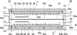
- FIG. 1 is a schematic cross-sectional view showing a first example of the artificial photosynthesis module according to the embodiment of the present invention
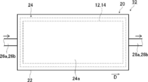
- FIG. 2 is a schematic plan view showing a first example of the artificial photosynthesis module according to the embodiment of the present invention. is there.
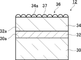
- FIG. 3 is a schematic cross-sectional view showing an example of an oxygen generating electrode
- FIG. 4 is a schematic cross-sectional view showing an example of a hydrogen generating electrode.
- FIG. 5 is a schematic perspective view showing a diaphragm.
- the artificial photosynthesis module 10 includes, for example, an oxygen generation electrode 12, a hydrogen generation electrode 14, and a diaphragm 16 provided between the oxygen generation electrode 12 and the hydrogen generation electrode 14.
- the artificial photosynthesis module 10 is a two-electrode water splitting module having an oxygen generating electrode 12 and a hydrogen generating electrode 14.
- the oxygen generating electrode 12 and the hydrogen generating electrode 14 are decomposed in water AQ while being immersed in water AQ. Used.
- the artificial photosynthesis module 10 includes a container 20 that houses an oxygen generation electrode 12, a hydrogen generation electrode 14, and a diaphragm 16.
- the container 20 is arrange
- the oxygen generation electrode 12 decomposes the water AQ while being immersed in the water AQ to generate oxygen gas.
- the oxygen generation electrode 12 has a flat plate shape as shown in FIG.
- the hydrogen generating electrode 14 decomposes the water AQ while being immersed in the water AQ to generate hydrogen gas, and has a flat plate shape as shown in FIG. 2, for example.
- the container 20 includes a housing 22 whose one surface is released, and a transparent member 24 that covers a released portion of the housing 22.
- the inside of the container 20 is partitioned into a first partition 23a on the transparent member 24 side and a second partition 23b on the bottom surface 22b side.
- the light L is, for example, sunlight and is incident from the transparent member 24 side. Also about the transparent member 24, it is preferable to satisfy
- the oxygen generation electrode 12 and the hydrogen generation electrode 14 are electrically connected by, for example, a conductive wire 18.
- the oxygen generation electrode 12 and the hydrogen generation electrode 14 are arranged in order of the oxygen generation electrode 12 and the hydrogen generation electrode 14 with the diaphragm 16 sandwiched in the container 20 in series along the traveling direction Di of the light L.
- the oxygen generation electrode 12 and the hydrogen generation electrode 14 are arranged so as to overlap each other with a gap therebetween.
- the gap Wd between the oxygen generation electrode 12 and the hydrogen generation electrode 14 is preferably 1 mm to 20 mm, and the smaller the gap, the better the energy conversion efficiency.
- the gap Wd between the oxygen generation electrode 12 and the hydrogen generation electrode 14 is the distance between the surface 34a of the first photocatalyst layer 34 of the oxygen generation electrode 12 and the surface 44a of the second photocatalyst layer 44 of the hydrogen generation electrode 14. .
- the oxygen generating electrode 12 is disposed in the first section 23a, and oxygen gas is generated in the first section 23a.
- the second substrate 40 is in contact with the bottom surface 22b and the hydrogen generating electrode 14 is disposed, and hydrogen gas is generated in the second compartment 23b.
- the light L is incident on the container 20 from the transparent member 24 side, that is, the light L is incident from the oxygen generation electrode 12 side.
- the traveling direction Di of the light L described above is a direction perpendicular to the surface 24 a of the transparent member 24.
- a supply pipe 26a is provided on the first wall surface 22c, and a discharge pipe 28a is provided on the second wall surface 22d facing the first wall surface 22c.
- a supply pipe 26b is provided on the first wall surface 22c, and a discharge pipe 28b is provided on the second wall surface 22d facing the first wall surface 22c.
- Water AQ is supplied into the container 20 from the supply pipe 26a and the supply pipe 26b, and the container 20 is filled with the water AQ.
- the water AQ flows in the direction D, and the water AQ containing oxygen is discharged from the discharge pipe 28a. Is recovered. Water AQ containing hydrogen is discharged from the discharge pipe 28b, and hydrogen is recovered.
- the flow direction F A water AQ is the direction D.
- the direction D is a direction from the first wall surface 22c toward the second wall surface 22d.
- casing 22 is comprised with an electrically insulating material of the grade which does not generate
- the housing 22 is made of, for example, acrylic resin. It is preferable that the container 20 satisfy
- the water AQ includes distilled water and cooling water used in a cooling tower or the like.
- the water AQ includes an electrolytic aqueous solution.
- the electrolytic aqueous solution is a liquid mainly composed of H 2 O, and may be an aqueous solution containing water as a solvent and containing a solute.
- strong alkaline KOH (potassium hydroxide)
- H 2 SO 4 an electrolyte solution containing 4 or a sodium sulfate electrolyte solution
- a potassium phosphate buffer solution or the like.
- H 3 BO 3 adjusted to pH (hydrogen ion index) 9.5 is preferable.
- the artificial photosynthesis module 10 may include a supply unit (not shown) for supplying water AQ and a recovery unit (not shown) for collecting water AQ discharged from the artificial photosynthesis module 10. .
- a known water supply device such as a pump can be used for the supply unit, and a known water recovery device such as a tank can be used for the recovery unit.
- the supply unit is connected to the artificial photosynthesis module 10 via the supply pipes 26a and 26b, and the recovery unit is connected to the artificial photosynthesis module 10 via the discharge pipes 28a and 28b to supply the water AQ recovered by the recovery unit. It is also possible to recycle water AQ by circulating the water. Further, water AQ is caused to flow parallel to the front surface 16a (see FIG. 5) and the back surface 16b (see FIG.
- the flow of water AQ does not include turbulent flow, and the flow of water AQ in the flow direction F A does not include turbulent flow.
- the oxygen generating electrode 12 includes a first substrate 30, a first conductive layer 32 provided on the first substrate 30, that is, on the surface 30a, and a first conductive layer. 32, that is, the first photocatalyst layer 34 provided on the surface 32a, and the first cocatalyst 36 supported on at least a part of the first photocatalyst layer 34.
- the oxygen generation electrode 12 is the first electrode.
- the first promoter 36 is composed of a plurality of promoter particles 37, for example. Thereby, the fall of the incident light quantity of the light L to the surface 34a of the 1st photocatalyst layer 34 is suppressed.
- the first cocatalyst 36 In the oxygen generating electrode 12, the first cocatalyst 36 must be in contact with the first photocatalyst layer 34, or be present through a layer in which holes can move, and in contact with water AQ.
- the absorption edge of the first photocatalyst layer 34 is, for example, about 400 nm to 800 nm.
- the absorption edge is a portion where the absorption rate suddenly decreases when the wavelength becomes longer in the continuous absorption spectrum or the edge thereof, and the unit of the absorption edge is nm.
- the oxygen generating electrode 12 preferably has a total thickness of about 2 mm.
- the oxygen generation electrode 12 can transmit the light L so that the light L is incident on the hydrogen generation electrode 14. In order to irradiate the hydrogen generating electrode 14 with the light L, the light L needs to pass through the oxygen generating electrode 12, and the first substrate 30 is transparent.
- the hydrogen generating electrode 14 does not need to be transparent in the second substrate 40 (see FIG. 4) described later.
- Transparent in the first substrate 30 means that the light transmittance of the first substrate 30 is at least 60% in the wavelength range of 380 nm to 780 nm.
- the above-mentioned light transmittance is measured by a spectrophotometer.
- the spectrophotometer for example, V-770 (product name) manufactured by JASCO Corporation, which is an ultraviolet-visible spectrophotometer, is used.
- T ( ⁇ (measurement substance + substrate) / ⁇ (substrate)) ⁇ 100%.
- the above-mentioned measurement substance is a glass substrate, and the substrate reference is air.
- the range of integration is up to the light receiving wavelength of the photocatalyst layer in the light with a wavelength of 380 nm to 780 nm.
- JIS Japanese Industrial Standard
- R 3106-1998 can be referred to for the measurement of light transmittance.
- the hydrogen generating electrode 14 includes a second substrate 40, a second conductive layer 42 provided on the second substrate 40, that is, on the surface 40a, and a second conductive layer. It has the 2nd photocatalyst layer 44 provided on the layer 42, ie, the surface 42a, and the 2nd cocatalyst 46 carry
- the hydrogen generation electrode 14 is the second electrode.
- the absorption edge of the second photocatalyst layer 44 of the hydrogen generating electrode 14 is, for example, about 600 nm to 1300 nm.
- the second promoter 46 is provided on the surface 44 a of the second photocatalyst layer 44.
- the second promoter 46 is composed of a plurality of promoter particles 47, for example. Thereby, the fall of the incident light quantity of the light L to the surface 44a of the 2nd photocatalyst layer 44 is suppressed.
- the hydrogen generation electrode 14 carriers generated when the light L is absorbed are generated, and water AQ is decomposed to generate hydrogen gas.
- it is also preferable to form a pn junction by laminating a material having n-type conductivity on the surface 44a of the second photocatalyst layer 44. Each configuration of the hydrogen generating electrode 14 will be described in detail later.
- the light L is incident from the oxygen generation electrode 12 side, and the oxygen generation electrode 12 is provided with the first photocatalyst layer 34 on the opposite side of the light L incidence side.
- the first photocatalyst layer 34 is provided on the opposite side of the light L incident side, so that the attenuation effect by the first photocatalyst layer 34 can be suppressed.
- the hydrogen generating electrode 14 is provided with a second photocatalyst layer 44 on the light L incident side.
- the diaphragm 16 is composed of a film having a through-hole 17 (see FIG. 5), and is immersed in pure water at a temperature of 25 ° C. for 1 minute.
- the light transmittance is 60% or more. That is, the diaphragm 16 has a minimum light transmittance of 60% in the wavelength range of 380 nm to 780 nm.
- the diaphragm 16 has a light transmittance of 60% or more in the wavelength range of 380 nm to 780 nm as described above, it is said to be transparent.
- the state in which the diaphragm 16 is immersed in pure water is a state in which the entire diaphragm 16 is in pure water and pure water is present on the front surface 16a and the back surface 16b of the diaphragm 16. .
- the transmittance of the diaphragm 16 is measured using a transmittance measuring device (SH7000 manufactured by Nippon Denshoku Industries Co., Ltd.). After the diaphragm 16 is immersed in pure water for 1 minute, the light transmittance of the diaphragm 16 is measured in a state of being immersed in pure water.
- the light transmittance is calculated by integrating all the light transmitted in the wavelength range of 380 nm to 780 nm with an integrating sphere as a transmitted light amount.
- the diaphragm 16 has a plurality of through holes 17.
- Each through-hole 17 penetrates from the front surface 16a to the back surface 16b, for example.
- the through-hole 17 is not particularly limited to one that penetrates the surface 16a perpendicularly to the surface 16a as long as it penetrates from the surface 16a to the back surface 16b.
- the opening of the mesh is the through hole 17.
- the network is the through hole 17.
- the diaphragm 16 is made of a fiber, a hole formed by a gap between the fibers is also included in the through hole 17.
- oxygen gas is generated at the oxygen generation electrode 12 and hydrogen gas is generated at the hydrogen generation electrode 14.
- the generated oxygen gas and the generated hydrogen gas are both dissolved in the water AQ.
- the oxygen gas and the hydrogen gas are dissolved. May exist in a gaseous state in water AQ.
- Oxygen gas bubbles are those in which oxygen gas not dissolved in water AQ is aggregated in water AQ.
- the hydrogen gas not dissolved in the water AQ is an aggregate in the water AQ is referred to as hydrogen gas bubbles.
- Both the oxygen gas bubbles and the hydrogen gas bubbles have a diameter of about 10 ⁇ m to 1 mm.
- the bubbles of oxygen gas and hydrogen gas are collectively referred to simply as bubbles.
- the diameter of the bubble is a diameter if the bubble is a sphere, and is an equivalent diameter corresponding to the diameter of the sphere if it is not a sphere.
- the oxygen gas bubbles and the hydrogen gas bubbles are on the surface of the first photocatalyst layer 34 of the oxygen generating electrode 12 and the surface of the second photocatalyst layer 44 of the hydrogen generating electrode 14 until both of the bubbles become a certain size. Therefore, bubbles having a small diameter, that is, bubbles having a small size do not exist in the water AQ.
- bubbles having a large diameter that is, bubbles having a large size, are detached from the surface of the first photocatalyst layer 34 of the oxygen generating electrode 12 and the surface of the second photocatalyst layer 44 of the hydrogen generating electrode 14, but the diaphragm 16. Is hydrophilic, it does not adhere to the diaphragm 16 and is carried from the container 20 to the outside by the flow of water AQ.
- the diameter of oxygen gas bubbles and the diameter of hydrogen gas bubbles can be measured as follows.
- the inside of the container 20 is imaged using a digital microscope including the surface of the first photocatalyst layer 34 of the oxygen generation electrode 12 and the surface of the second photocatalyst layer 44 of the hydrogen generation electrode 14 and is magnified and imaged.
- a captured image in the container 20 is obtained.
- Check for bubbles in the captured image For example, VHX-5000 manufactured by Keyence Corporation can be used for the digital microscope, and image analysis software for VHX-5000 users (manufactured by Keyence Corporation) can be used for air bubble confirmation.
- the average bubble diameter can be obtained by obtaining the bubble diameter of the oxygen gas bubbles and the bubble diameter of the hydrogen gas bubbles.
- the diaphragm 16 allows water AQ to pass through, but does not allow oxygen gas bubbles and hydrogen gas bubbles to pass therethrough. For this reason, it is preferable that the diaphragm 16 has the through-holes 17 having a pore diameter smaller than the average bubble diameter of the oxygen gas bubbles 50 and the average bubble diameter of the hydrogen gas bubbles 52. Specifically, as shown in FIG. 5, when the average bubble diameter of the oxygen gas bubbles 50 and the hydrogen gas bubbles 52 is Db and the hole diameter of the through holes 17 is Dh, Dh ⁇ Db.
- the average pore diameter of the through holes 17 of the diaphragm 16 is more than 0.1 ⁇ m and less than 50 ⁇ m, preferably more than 1 ⁇ m and less than 50 ⁇ m. If the average hole diameter of the through-holes 17 is more than 0.1 ⁇ m and less than 50 ⁇ m, the water AQ passes through the through-holes 17, and as a result, oxygen gas and hydrogen gas dissolved in the water AQ pass through the diaphragm 16. The passage of the bubbles 50 and the bubbles 52 of hydrogen gas is suppressed.
- the size of protons and ions that need to pass is much smaller than the pore size, and in the diaphragm 16, unlike Nafion (registered trademark), resistance does not occur due to the passage of protons and ions. For this reason, about the diaphragm 16, since the one where a hole diameter is larger can make a film thickness thick, it is excellent in durability and preferable.
- a polymer electrolyte such as Nafion (registered trademark)
- only protons and ions necessary for electrolysis are conducted by water molecules contained between the polymers.
- the diaphragm 16 does not allow air bubbles of a certain size to pass therethrough, but the water AQ itself has large pores that can freely go back and forth.
- the conductivity of ions is high, and the electrolysis voltage can be kept low.
- hydrogen generated conventionally has been required to have high purity, it is impossible to conceive of the diaphragm 16 itself, in which the water AQ itself can freely move back and forth to reduce the purity of hydrogen. .
- the average pore diameter of the through-holes 17 of the diaphragm 16 is determined using the following microscopic observation method.
- the surface 16a of the diaphragm 16 is observed with an electron microscope at a magnification of about 100 to 10,000 times.
- images of at least 20 through-holes 17 selected in descending order are picked up, and a circle that is inscribed in the through-hole 17 is formed with respect to the indeterminate through-hole 17 appearing in the image obtained by the image pickup.
- the diameter of the inscribed circle is defined as the diameter of the through hole 17.
- the standard deviation ⁇ of the hole diameter distribution of at least 20 through holes 17 is calculated, and the size covering 3 ⁇ is obtained.
- the size covering 3 ⁇ is defined as the average hole diameter of the through holes 17 of the diaphragm 16.
- “Particle Analysis Ver.3.5” manufactured by Nippon Steel & Sumikin Technology Co., Ltd. can be used as analysis software.
- the minimum diameter of “Particle Analysis Ver.3.5” corresponds to the diameter of the inscribed circle.
- the average pore diameter of the through holes 17 of the diaphragm 16 may be a catalog value.
- the light transmittance of the diaphragm 16 is dependent on the thickness of the diaphragm 16. Therefore, it is preferable that the diaphragm 16 has a thickness d at which the light transmittance in the wavelength region of 380 nm to 780 nm is 60% at the minimum.
- the thickness d is preferably 0.01 mm to 0.5 mm, and the upper limit of the thickness d is more preferably 0.2 mm.
- the thickness d of the diaphragm 16 is the distance between the front surface 16a and the back surface 16b of the diaphragm 16.
- the diaphragm 16 is preferably composed of a porous film having a hydrophilic surface. That is, it is preferable that the front surface 16a and the back surface 16b of the diaphragm 16 be a porous film having a hydrophilic surface.
- the front surface 16a and the back surface 16b of the diaphragm 16 are surfaces in contact with oxygen gas bubbles 50 or hydrogen gas bubbles 52, respectively.
- the hydrophilic surface may be the property of the diaphragm 16 itself, or may be subjected to a hydrophilic treatment to form a hydrophilic surface.
- PTFE polytetrafluoroethylene
- PTFE usually has water repellency, but, for example, by subjecting it to a hydrophilic treatment such as immersion in alcohol, the contact angle with respect to water becomes small and exhibits hydrophilicity.
- a hydrophilic treatment such as immersion in alcohol
- crosslinking In this method, durability of a hydrophilization process can be improved.
- the method shown in WO2014 / 2167 can also be used as the hydrophilic treatment.
- the hydrophilic surface is defined by the contact angle with water. The hydrophilicity and hydrophobicity are determined based on [Measurement and determination of hydrophilicity and hydrophobicity] described later.
- the diaphragm 16 having a hydrophilic surface By using the diaphragm 16 having a hydrophilic surface, water AQ can easily penetrate into the diaphragm 16, and the through holes 17 are not blocked by the oxygen gas bubbles 50 or the hydrogen gas bubbles 52. As a result, the water AQ easily passes through the through-holes 17 of the diaphragm 16, and as a result, the protons and ions in the water AQ easily pass and the energy conversion efficiency increases. Further, by forming the diaphragm 16 having a hydrophilic surface, the oxygen gas bubbles 50 or the hydrogen gas bubbles 52 are repelled by the front surface 16a and the back surface 16b of the diaphragm 16, and the oxygen gas bubbles 50 and the hydrogen gas bubbles 52 are formed. It becomes difficult to pass through the through hole 17.
- oxygen gas and hydrogen gas can be recovered. Since the oxygen gas bubbles 50 and the hydrogen gas bubbles 52 are less likely to pass through the through-hole 17, the oxygen gas bubbles 50 and the hydrogen gas bubbles 52 are less likely to adhere to the front surface 16 a and the back surface 16 b of the diaphragm 16. The gas bubbles 50 and the hydrogen gas bubbles 52 are quickly discharged together with the flow of water AQ. Further, since the oxygen gas bubbles 50 and the hydrogen gas bubbles 52 do not adhere to the diaphragm 16, the effective area of the diaphragm 16 is ensured, and the energy conversion efficiency is increased. Further, when oxygen gas bubbles 50 and hydrogen gas bubbles 52 adhere to the diaphragm 16, the utilization efficiency of the light L may be lowered, but this is also suppressed and the energy conversion efficiency is increased.
- reference numeral 80 denotes a Nafion (registered trademark) film having a thickness of 0.1 mm.
- Reference numeral 82 denotes a porous cellulose membrane.
- Reference numeral 84 is a hydrophilic PTFE (polyethylene terephthalate) membrane having a pore diameter of 0.1 ⁇ m
- reference numeral 86 is a hydrophilic PTFE (polyethylene terephthalate) membrane having a pore diameter of 1.0 ⁇ m
- reference numeral 88 is a hydrophilic PTFE (polyethylene terephthalate) having a pore diameter of 10 ⁇ m.
- the membrane is shown.
- Reference numeral 89 denotes a hydrophilic PTFE membrane having a pore diameter of 10 ⁇ m, and is a transmittance measured in air.
- Reference numerals 80, 82, 84, 86, and 88 other than the reference numeral 89 are light transmittances in a state where they are immersed in pure water at a temperature of 25 ° C. for 1 minute and immersed in pure water.
- Nafion (registered trademark) conventionally used for a diaphragm is not a porous membrane.
- the porous cellulose film denoted by reference numeral 82 has low light resistance.
- hydrophilic PTFE polyethylene terephthalate films denoted by reference numerals 84, 86 and 88 shown in FIG.
- the hydrophilic PTFE membrane looks white in the air and has a low transmittance as indicated by reference numeral 89.
- the diaphragm 16 is made of a porous film as described above, and is transparent when immersed in pure water.
- Water AQ is supplied into the first compartment 23a of the container 20 through the supply pipe 26a
- water AQ is supplied into the second compartment 23b of the container 20 through the supply pipe 26b
- the light L is transmitted through the transparent member 24.
- water AQ containing oxygen gas is discharged
- Water AQ containing hydrogen gas is discharged from the discharge pipe 28b, and hydrogen is recovered from the discharged water AQ containing hydrogen gas.
- water AQ passes through the diaphragm 16 as described above, unlike the ion exchange membrane.
- the oxygen gas and hydrogen gas dissolved in the water AQ pass through the through-hole 17, but the oxygen gas bubbles 50 and the hydrogen gas bubbles 52 are less likely to pass through the through-hole 17, and as described above, the electrolytic efficiency That is, the energy conversion efficiency increases.
- the oxygen generation electrode 12 and the hydrogen generation electrode 14 are arranged in series along the traveling direction Di of the light L, and the light L is used by the oxygen generation electrode 12 and the hydrogen generation electrode 14.
- the utilization efficiency of the light L can be increased, and the energy conversion efficiency is high. That is, the current density indicating water splitting can be increased.
- energy conversion efficiency can be increased without increasing the installation area of the oxygen generation electrode 12 and the hydrogen generation electrode 14.
- the absorption edge of the first photocatalyst layer 34 of the oxygen generation electrode 12 is, for example, about 500 nm to 800 nm
- the absorption edge of the second photocatalyst layer 44 of the hydrogen generation electrode 14 is For example, it is about 600 nm to 1300 nm.
- the absorption edge of the first photocatalyst layer 34 of the oxygen generation electrode 12 is ⁇ 1
- the absorption edge of the second photocatalyst layer 44 of the hydrogen generation electrode 14 is ⁇ 2 , ⁇ 1 ⁇ 2
- the light L when the light L is sunlight, the light L is used as the hydrogen generating electrode even if the first photocatalyst layer 34 of the oxygen generating electrode 12 is first used to generate oxygen by absorbing light of a specific wavelength. 14 is absorbed in the second photocatalyst layer 44 and can be used for generation of hydrogen, and the hydrogen generation electrode 14 provides a necessary amount of carrier generation. Thereby, the utilization efficiency of light L can be raised more.
- connection form is not particularly limited, and is not limited to the conductive wire 18.
- the hydrogen generation electrode 14 and the oxygen generation electrode 12 should just be electrically connected, and the connection method is not specifically limited.
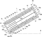
- the artificial photosynthesis module 10 is arranged with the container 20 on the horizontal plane B, but may be arranged with a predetermined angle ⁇ tilted with respect to the horizontal plane B as shown in FIG.
- the discharge pipe 28a and the discharge pipe 28b are higher than the supply pipe 26a and the supply pipe 26b, and the generated oxygen gas and hydrogen gas are easily recovered.
- the generated oxygen gas can be quickly moved from the oxygen generating electrode 12, and the generated hydrogen gas can be quickly moved from the hydrogen generating electrode 14. Accordingly, retention of the generated oxygen gas bubbles and hydrogen gas bubbles can be suppressed, and the light L is prevented from being blocked by the generated oxygen gas bubbles and hydrogen gas bubbles. For this reason, it is possible to reduce the influence of the generated oxygen gas and hydrogen gas on the reaction efficiency.
- the inclination angle is not particularly limited, and sunlight can be efficiently used by inclining in the sunlight incident direction according to the latitude.
- the oxygen generation electrode 12 that is an example of the first electrode and the hydrogen generation electrode 14 that is an example of the second electrode will be described.
- a photocatalyst layer and a promoter suitable for the oxygen generating electrode 12 will be described.
- a known photo catalyst can be used, and is a photo semiconductor containing at least one metal element.
- the metal element Ti, V, Nb, Ta, W, Mo, Zr, Ga, and the like are preferable in that the onset potential is better, the photocurrent density is higher, or the durability by continuous irradiation is more excellent.
- Zn, Cu, Ag, Cd, Cr, or Sn is preferable, and Ti, V, Nb, Ta, or W is more preferable.
- the optical semiconductor include oxides, nitrides, oxynitrides, sulfides, and selenides containing the above metal elements.
- the photocatalyst layer usually contains a photo semiconductor as a main component.
- the main component means that the optical semiconductor is 80% by mass or more with respect to the total mass of the second photocatalyst layer, and preferably 90% by mass or more. Although an upper limit is not specifically limited, It is 100 mass%.
- optical semiconductor examples include, for example, Bi 2 WO 6 , BiVO 4 , BiYWO 6 , In 2 O 3 (ZnO) 3 , InTaO 4 , InTaO 4 : Ni (“optical semiconductor: M” is M in the optical semiconductor.
- a doped body containing AB (O, N) 3 as a main component can be used.
- the shape of the optical semiconductor contained in the photocatalyst layer is not particularly limited, and examples thereof include a film shape, a column shape, and a particle shape.
- the particle size of the primary particles is not particularly limited, but is usually preferably 0.01 ⁇ m or more, more preferably 0.1 ⁇ m or more, and usually 10 ⁇ m or less. More preferably, it is 2 ⁇ m or less.
- the above-mentioned particle size is an average particle size, and the particle size (diameter) of any 100 optical semiconductors observed with a transmission electron microscope or a scanning electron microscope is measured and arithmetically averaged. . If the particle shape is not a perfect circle, the major axis is measured.
- the optical semiconductor When the optical semiconductor is columnar, it is preferably a columnar optical semiconductor that extends along the normal direction of the surface of the conductive layer.
- the diameter of the columnar optical semiconductor is not particularly limited, but is usually preferably 0.025 ⁇ m or more, more preferably 0.05 ⁇ m or more, and usually 10 ⁇ m or less, more preferably 2 ⁇ m or less. .
- the above-mentioned diameter is an average diameter, and is observed with a transmission electron microscope (device name: Hitachi High-Technologies Corporation H-8100) or a scanning electron microscope (device name: Hitachi High-Technologies Corporation SU-8020 model SEM). Further, the diameters of 100 arbitrary columnar optical semiconductors are measured, and they are arithmetically averaged.
- the thickness of a photocatalyst layer is not specifically limited, In the case of an oxide or nitride, it is preferable that it is 300 nm or more and 2 micrometers or less. Note that the optimum thickness of the photocatalyst layer is determined by the penetration length of the light L or the diffusion length of the excited carriers.
- many photocatalyst layer materials such as BiVO 4 that is often used as a photocatalyst layer material, have a reaction efficiency that is not maximum at such a thickness that all light having a wavelength that can be absorbed can be utilized. When the thickness is large, it is difficult to transport carriers generated at a place far from the film surface to the film surface without deactivation due to problems of carrier life and mobility.
- the thickness of the photocatalyst layer is 300 nm or more and 2 ⁇ m or less, current can be taken out.
- the thickness of the photocatalyst layer can be obtained from an acquired image obtained by acquiring a scanning electron microscope image of the cross-sectional state of the photocatalyst electrode.
- the method for forming the photocatalyst layer is not particularly limited, but a known method (for example, a method of depositing a particulate photo semiconductor on a substrate) can be employed.
- a known method for example, a method of depositing a particulate photo semiconductor on a substrate
- Specific examples of the forming method include vapor deposition methods such as an electron beam evaporation method, a sputtering method, and a CVD (Chemical Vapor Deposition) method, a transfer method described in Chem. Sci., 2013, 4, 1120-1124, Adv. Mater. , 2013, 25, 125-131.
- another layer for example, an adhesive layer, may be included between the substrate and the photocatalyst layer as necessary.
- the cocatalyst is supported using a vacuum deposition method, a sputtering method, an electrodeposition method, or the like.
- the cocatalyst is formed with a set film thickness of, for example, about 1 nm to 5 nm, it is not formed as a film but becomes an island shape.
- the first co-catalyst 36 include simple substances composed of Pt, Pd, Ni, Au, Ag, Ru, Cu, Co, Rh, Ir, Mn, Fe, and the like, and alloys combining them.
- the oxides thereof for example, CoOx such as FeOx and CoO, NiOx and RuO 2 can be used.
- the second substrate 40 of the hydrogen generation electrode 14 shown in FIG. 4 supports the second photocatalyst layer 44 and is configured to have electrical insulation.
- the second substrate 40 is not particularly limited.
- a soda lime glass substrate or a ceramic substrate can be used.
- the second substrate 40 may be a metal substrate having an insulating layer formed thereon.
- a metal substrate such as an Al substrate or a SUS (Steel Stainless) substrate, or a composite metal substrate such as a composite Al substrate made of a composite material of Al and another metal such as SUS, for example.
- the composite metal substrate is also a kind of metal substrate, and the metal substrate and the composite metal substrate are collectively referred to simply as a metal substrate.
- the second substrate 40 a metal substrate with an insulating film having an insulating layer formed by anodizing the surface of an Al substrate or the like can also be used.
- the second substrate 40 may or may not be flexible.
- a glass plate such as high strain point glass and non-alkali glass, or a polyimide material can be used.
- the thickness of the second substrate 40 is not particularly limited, and may be, for example, about 20 ⁇ m to 2000 ⁇ m, preferably 100 ⁇ m to 1000 ⁇ m, and more preferably 100 ⁇ m to 500 ⁇ m.
- the alkali ion for example, sodium (Na) ion: If there is a material that supplies Na + ), the photoelectric conversion efficiency is improved. Therefore, it is preferable to provide an alkali supply layer that supplies alkali ions on the surface 40 a of the second substrate 40. Note that when the constituent element of the second substrate 40 contains an alkali metal, the alkali supply layer is unnecessary.
- the second conductive layer 42 collects and transports the carriers generated in the second photocatalyst layer 44.
- the 2nd conductive layer 42 has electroconductivity,
- it is comprised with metals, such as Mo, Cr, and W, or those which combined these.
- the second conductive layer 42 may have a single layer structure or a laminated structure such as a two-layer structure. Of these, the second conductive layer 42 is preferably composed of Mo.
- the second conductive layer 42 preferably has a thickness of 200 nm to 1000 nm.
- the second photocatalyst layer 44 which generates a carrier by light absorption, are intended to be monument side than the potential (H 2 / H +) to the conduction band lower end to produce hydrogen by decomposing water.
- the second photocatalyst layer 44 has a p-type conductivity that generates holes and transports them to the second conductive layer 42.
- the surface 44a of the second photocatalyst layer 44 has an n-type conductivity. It is also preferable to form a pn junction by stacking layers.
- the thickness of the second photocatalyst layer 44 is preferably 500 nm to 3000 nm.
- the optical semiconductor constituting the p-type conductivity is an optical semiconductor containing at least one metal element.
- the metal element Ti, V, Nb, Ta, W, Mo, Zr, Ga, and the like are preferable in that the onset potential is better, the photocurrent density is higher, or the durability by continuous irradiation is more excellent.
- Zn, Cu, Ag, Cd, Cr, or Sn is preferable, and Ga, In, Zn, Cu, Zr, or Sn is more preferable.
- examples of the optical semiconductor include oxides, nitrides, oxynitrides, (oxy) chalcogenides, and the like containing the above metal elements, and include GaAs, GaInP, AlGaInP, CdTe, CuInGaSe, and a CIGS compound having a chalcopyrite crystal structure. It is preferably composed of a semiconductor or a CZTS compound semiconductor such as Cu 2 ZnSnS 4 . A CIGS compound semiconductor having a chalcopyrite crystal structure or a CZTS compound semiconductor such as Cu 2 ZnSnS 4 is particularly preferable.
- the CIGS compound semiconductor layer may be composed of not only Cu (In, Ga) Se 2 (CIGS) but also CuInSe 2 (CIS), CuGaSe 2 (CGS), or the like. Further, the CIGS compound semiconductor layer may be formed by replacing all or part of Se with S.
- CIGS compound semiconductor layer As a formation method of a CIGS compound semiconductor layer, 1) multi-source vapor deposition method, 2) selenization method, 3) sputtering method, 4) hybrid sputtering method, and 5) mechanochemical process method are known. Examples of other CIGS compound semiconductor layer forming methods include screen printing, proximity sublimation, MOCVD (Metal Organic Chemical Vapor Deposition), and spray (wet film formation).
- a fine particle film containing a group 11 element, a group 13 element, and a group 16 element is formed on a substrate by a screen printing method (wet film forming method) or a spray method (wet film forming method), and a thermal decomposition treatment ( At this time, a crystal having a desired composition can be obtained by performing a thermal decomposition treatment in a group 16 element atmosphere) (JP-A-9-74065, JP-A-9-74213, etc.).
- the CIGS compound semiconductor layer is also simply referred to as a CIGS layer.
- a pn junction is formed.
- materials having n-type conductivity include CdS, ZnS, Zn (S, O), and / or Zn (S, O, OH), SnS, Sn (S, O), and / or Sn (S, S, O).
- the film thickness of the material layer having n-type conductivity is preferably 20 nm to 100 nm.
- the layer of material having n-type conductivity is formed by, for example, a CBD (Chemical Bath Deposition) method.
- the configuration of the second photocatalyst layer 44 is not particularly limited as long as the second photocatalyst layer 44 is made of an inorganic semiconductor and can generate hydrogen gas by causing a photodecomposition reaction of water and generating hydrogen gas.
- the photoelectric conversion element used for the photovoltaic cell which comprises a solar cell is used preferably.
- a photoelectric conversion element in addition to the above-described CIGS compound semiconductor or a CZTS compound semiconductor such as Cu 2 ZnSnS 4 , a thin film silicon thin film photoelectric conversion element, a CdTe thin film photoelectric conversion element, and a dye A sensitized thin film photoelectric conversion element or an organic thin film photoelectric conversion element can be used.
- ⁇ Promoter for hydrogen generating electrode As the second promoter 46, for example, Pt, Pd, Ni, Ag, Ru, Cu, Co, Rh, Ir, Mn, and RuO 2 are preferably used.
- a transparent conductive layer (not shown) may be provided between the second photocatalyst layer 44 and the second promoter 46.
- the transparent conductive layer is required to have a function of electrically connecting the second photocatalyst layer 44 and the second promoter 46, and the transparent conductive layer is required to have transparency, water resistance, and water shielding, The durability of the hydrogen generating electrode 14 is improved by the transparent conductive layer.
- the transparent conductive layer is preferably, for example, a metal, a conductive oxide (overvoltage is 0.5 V or less), or a composite thereof.
- the transparent conductive layer is appropriately selected according to the absorption wavelength of the second photocatalyst layer 44.
- ITO Indium Tin Oxide
- FTO fluorine-doped tin oxide
- ZnO doped with Al, B, Ga, or In or IMO (In 2 O 3 doped with Mo), etc.
- the transparent conductive film can be used.
- the transparent conductive layer may have a single layer structure or a laminated structure such as a two-layer structure.
- the thickness of the transparent conductive layer is not particularly limited, and is preferably 30 nm to 500 nm.
- the method for forming the transparent conductive layer is not particularly limited, but a vacuum film formation method is preferable, and it is formed by a vapor phase film formation method such as an electron beam evaporation method, a sputtering method, or a CVD (Chemical Vapor Deposition) method. can do.
- a vapor phase film formation method such as an electron beam evaporation method, a sputtering method, or a CVD (Chemical Vapor Deposition) method. can do.
- a protective film for protecting the second promoter 46 may be provided on the surface of the second promoter 46 instead of the transparent conductive layer.
- the protective film is composed of one that matches the absorption wavelength of the second promoter 46.
- an oxide such as TiO 2 , ZrO 2, and Ga 2 O 3 is used.
- the protective film is an insulator, for example, the thickness is 5 nm to 50 nm, and a film forming method such as an ALD (Atomic Layer Deposition) method is selected.
- the protective film When the protective film is conductive, for example, it has a thickness of 5 nm to 500 nm, and can be formed by sputtering or the like in addition to ALD (Atomic Layer Deposition) and CVD (Chemical Vapor Deposition).
- the protective film can be made thicker in the case of the conductor than in the case of the insulating property.
- the oxygen generation electrode 12 and the hydrogen generation electrode 14 are both flat as a whole, but the present invention is not limited to this, and a structure having a through-hole penetrating in the thickness direction of the electrode may be used.
- the electrode configuration may be a mesh electrode.
- the oxygen generating electrode 12 may be a mesh-like electrode as a whole.
- the first substrate 30 may be formed of a mesh or a sheet having a plurality of through holes.
- the hydrogen generation electrode 14 or the whole electrode may be a mesh-like electrode
- the second substrate 40 may be formed of a mesh or a sheet body having a plurality of through holes.
- FIG. 8 is a schematic cross-sectional view showing a third example of the artificial photosynthesis module according to the embodiment of the present invention.
- FIG. 9 is a schematic cross-sectional view showing a fourth example of the artificial photosynthesis module according to the embodiment of the present invention. 8 and 9, the same components as those of the artificial photosynthesis module shown in FIG.
- the raw material fluid is water
- the first fluid is oxygen
- the second fluid is the same as the first example of the artificial photosynthesis module described above. Hydrogen.
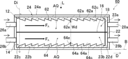
- the artificial photosynthesis module 60 shown in FIG. 8 has the same configuration as the artificial photosynthesis module 10 shown in FIG. 1 except that the configurations of the oxygen generation electrode 12 and the hydrogen generation electrode 14 are different.
- the oxygen generation electrode 12 and the hydrogen generation electrode 14 are shown in cross-sectional shapes. The same as module 10.
- the oxygen generation electrode 12 and the hydrogen generation electrode 14 are provided with at least one protrusion that protrudes with respect to the diaphragm 16.
- Protrusion may be configured provided with a plurality against water AQ flow direction F A.
- the protrusions 62 a that are the protrusions 62 and the recesses 62 b are alternately arranged in the direction D.
- the convex portions 64 a that are the protruding portions 64 and the concave portions 64 b are alternately arranged with respect to the direction D.
- the convex part 62a and the concave part 62b of the oxygen generating electrode 12 can be formed by machining such as cutting an uneven groove on the surface of the first substrate 30, for example.
- the convex portions 64a and the concave portions 64b of the hydrogen generating electrode 14 can also be formed on the surface of the second substrate 40 by machining such as cutting as described above.
- the convex portions 62a and concave portions 62b are repeatedly provided to the flow direction F A water AQ, with a rectangular concavo-convex structure.
- Protrusions 62a surface 62c is a surface parallel to the flow direction F A water AQ.
- Recesses 62b are surface 62d is a surface parallel to the flow direction F A water AQ.
- the convex portions 64a and concave portions 64b are repeatedly provided to the flow direction F A water AQ, with a rectangular concavo-convex structure.
- Protrusions 64a surface 64c is a surface parallel to the flow direction F A water AQ.
- the concave portion 64b is a surface whose surface 64d is parallel to the flow direction F A of the water AQ.
- the convex portion 62a is arranged on the upstream side in the flow direction F A, the present invention is not limited to this, and the concave portion 62b may be arranged on the upstream side in the flow direction F A by replacing the convex portion 62a and the concave portion 62b. .
- the number of the convex portions 62a and the concave portions 62b in the protruding portion 64 may be at least one, and the number of the convex portions 62a and the number of the concave portions 62b may be the same or different.
- the length of the water AQ flow direction F A length and recess 62b of the water AQ flow direction F A of the convex portion 62a can be different even for the same.
- the length of the water AQ flow direction F A of the convex portion 62a is that the pitch of the projecting portion 64 with respect to the flow direction F A water AQ, is preferably less than 1.0mm 20mm or less.
- the length of the water AQ flow direction F A of the convex portion 62a is 1.0mm or 20mm or less, it is possible to obtain a high electrolytic current.
- the length of the water AQ flow direction F A recess 62b is not particularly limited, may be the same as the length of the water AQ flow direction F A of the convex portion 62a, for example, 1.0 mm It may be 20 mm or less.
- the height from the surface 62d of the recessed part 62b of the protrusion part 62 is 0.1 mm or more and 5.0 mm or less.
- the protrusion 62 has a height of unevenness, that is, a height h of 0.1 mm or more.
- the above-mentioned height is a distance from the surface 62d of the concave portion 62b to the surface 62c of the convex portion 62a. If the height is 0.1 mm or more and 5.0 mm or less, a high electrolysis current can be obtained.
- a narrower interval Wd between the oxygen generating electrode 12 and the hydrogen generating electrode 14 is preferable because of higher efficiency, and the interval Wd is preferably 1 mm to 20 mm.
- the interval Wd is the distance between the surface 62c of the convex portion 62a of the oxygen generating electrode 12 and the surface 64c of the convex portion 64a of the hydrogen generating electrode 14.
- a method for measuring the length of the water AQ in the flow direction F A of the convex portions 62a and 64a, the length of the water AQ in the flow direction F A of the concave portions 62b and 64b, and the above-described height will be described.
- a digital image is acquired from the side surface direction of the protruding portion 64, the digital image is taken into a personal computer, displayed on a monitor, and a line corresponding to the above length and the above height is displayed on the monitor. Then, find the length of each line. Thereby, the above-mentioned length and the above-mentioned height can be obtained.
- the oxygen generation electrode 12 and the hydrogen generation electrode 14 may have the same length or the same height as described above.
- the convex part 62a of the protrusion part 62 and the convex part 64a of the protrusion part 64 are provided in the range of 50% or more with respect to the area of the surface in which the protrusion parts 62 and 64 were provided.
- the total length of the oxygen generation electrode 12 and the hydrogen generation electrode 14 is half or more.
- the total length of the convex portions 62a and 64a is preferably half or more of the length Wc. For this reason, by making the total number of the convex parts 62a and 64a larger than the total number of the concave parts 62b and 64b, the range of 50% or more with respect to the area of the surface on which the projecting parts 62 and 64 are provided. Can do.
- a water AQ when flowing in a direction parallel to the direction D, the flow direction F A water AQ is a direction parallel to the direction D, transverse protrusions 62a, 64a and the recess 62b, and 64b Direction.
- the oxygen generation electrode 12 and the hydrogen generation electrode 14 have a rectangular uneven structure as described above, so that a turbulent flow is generated in the flow of water AQ and oxygen gas adhering to the diaphragm 16 flows. The effect that the bubbles and the bubbles of hydrogen gas are peeled off is obtained, and the decrease in the utilization efficiency of the light L is suppressed. Thereby, an electrolysis voltage falls and energy conversion efficiency rises.
- the protruding portion 62 of the oxygen generating electrode 12 and the protruding portion 64 of the hydrogen generating electrode 14 both have convex portions 62a and 64a whose surfaces 62c and 64c are inclined surfaces. Further, it may be arranged continuously with respect to the flow direction F A of the water AQ and have a periodic structure in which the height from the surface changes periodically with respect to the flow direction F A of the water AQ. Even in this case, the turbulent flow is generated in the flow of the water AQ as in the rectangular uneven structure described above, and the effect of peeling off the oxygen gas bubbles and the hydrogen gas bubbles adhering to the diaphragm 16 is obtained. Reduction in utilization efficiency is suppressed.
- the inclination angle of the slope although 90 ° or less with respect to water AQ flow direction F A, the embodiment is not limited thereto. Angle of inclination may be greater than 90 °, in this case, the inclined surface is inclined against the flow direction F A water AQ.
- the inclination angle is preferably 5 ° or more and 45 ° or less, and more preferably the upper limit value is 30 ° or less.
- the lower limit value of the tilt angle is 5 °, for example. If the tilt angle is 45 ° or less, a high electrolysis current can be obtained.
- a narrower interval Wd between the oxygen generating electrode 12 and the hydrogen generating electrode 14 is preferable because of higher efficiency, and the interval Wd is preferably 1 mm to 20 mm.
- the interval Wd is the distance between the most protruding end 62e of the surface 62c of the convex portion 62a of the oxygen generating electrode 12 and the most protruding end 64e of the surface 64c of the convex portion 64a of the hydrogen generating electrode 14.
- the inclination angle of the oxygen generation electrode 12 and the hydrogen generation electrode 14 is obtained by acquiring a digital image from the side surface direction of the oxygen generation electrode 12 and the hydrogen generation electrode 14, expecting the digital image to be captured on a personal computer, and displaying it on a monitor. Then, a horizontal line is drawn, and an angle formed by the horizontal line and the surfaces of the oxygen generating electrode 12 and the inclined surface of the hydrogen generating electrode 14 is obtained.
- the sizes of the protrusions 62 and 64 may be the same or different.
- Either one of the oxygen generation electrode 12 and the hydrogen generation electrode 14 may be configured as a so-called solid electrode having no protrusion.
- the entire surface is relative to the flow direction F A water AQ, may be configured to have inclined so that the thickness becomes thicker.
- the inclination angles of the oxygen generation electrode 12 and the hydrogen generation electrode 14 may be the same or different.
- the entire surface is relative to the flow direction F A water AQ, it may be configured inclined such that the thickness becomes thinner.
- the inclination angles of the oxygen generation electrode 12 and the hydrogen generation electrode 14 may be the same or different. In any of the above cases, the inclination angle is preferably 5 ° or more and 45 ° or less.
- FIGS. 10 and 7 and the artificial photosynthesis module 60 shown in FIGS. 8 and 9 both are arranged in order of the oxygen generation electrode 12 and the hydrogen generation electrode 14 from the incident side of the light L.
- the configuration is not limited to this, and the hydrogen generation electrode 14 and the oxygen generation electrode 12 may be arranged in this order.
- the oxygen generating electrode 12 and the hydrogen generating electrode 14 may have a comb structure shown in FIGS.
- FIG. 10 is a schematic sectional view showing a fifth example of the artificial photosynthesis module of the embodiment of the present invention
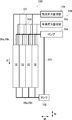
- FIG. 11 shows the electrode configuration of the fifth example of the artificial photosynthesis module of the embodiment of the present invention. It is a schematic plan view to show.
- the artificial photosynthesis module 70 shown in FIG. 10 has the same configuration as the artificial photosynthesis module 10 shown in FIG. 1 except that the configurations of the oxygen generation electrode 12 and the hydrogen generation electrode 14 are different.
- the oxygen generation electrode 12 and the hydrogen generation electrode 14 of the artificial photosynthesis module 70 shown in FIG. is there.
- the first photocatalytic layer 34 (see FIG. 3) of the oxygen generating electrode 12 is provided on the light L incident side.
- the second photocatalytic layer 44 (see FIG. 4) of the hydrogen generating electrode 14 is also provided on the light L incident side.
- the oxygen generation electrode 12 is configured by, for example, a flat plate, and includes a rectangular first electrode portion 72 a, a rectangular first gap 72 b, and a plurality of first electrode portions 72 a. Are connected to each other, and the first electrode portions 72a and the first gaps 72b are alternately arranged in the direction D.
- the plurality of first electrode portions 72a are integral with the base portion 72c, and the plurality of first electrode portions 72a are electrically connected to each other.
- the hydrogen generation electrode 14 is formed of, for example, a flat plate, and includes a rectangular second electrode portion 74a, a rectangular second gap 74b, and a base portion 74c to which the plurality of second electrode portions 74a are connected.
- the second electrode portions 74a and the second gaps 74b are alternately arranged in the direction D.
- the plurality of second electrode portions 74a are integral with the base portion 74c, and the plurality of second electrode portions 74a are electrically connected to each other.
- the arrangement direction of the first electrode part 72a and the arrangement direction of the second electrode part 74a are parallel to the direction D.
- the oxygen generating electrode 12 and the hydrogen generating electrode 14 are both comb-like electrodes, and the first electrode portion 72a and the second electrode portion 74a correspond to comb teeth of the comb-tooth electrode. To do.
- the oxygen generation electrode 12 and the hydrogen generation electrode 14 are both called comb electrodes.
- the oxygen generation electrode 12 and the hydrogen generation electrode 14 are arranged such that the first electrode portion 72a is disposed in the second gap 74b, and the second electrode portion 74a is the first gap. 72b. In this case, there may be a gap in the direction D between the second gap 74b and the first electrode portion 72a.
- the flow direction F A water AQ is a direction parallel to the direction D, water AQ flows across the first electrode portion 72a and the second electrode portion 74a.
- the oxygen generation electrode 12 and the hydrogen generation electrode 14 are arranged in this order from the light L incident side, but the configuration is not limited to this, and the hydrogen generation electrode is not limited to this configuration. 14.
- the order of the oxygen generation electrode 12 may be sufficient.
- the oxygen generating electrode 12 may be disposed on the opposite side of the diaphragm 16 from the incidence of the light L.
- the oxygen generation electrode 12 has an absorption edge of, for example, about 400 nm to 800 nm. Therefore, it is preferable that the diaphragm 16 has a high transmittance even in the ultraviolet region where the wavelength is around 400 nm.
- the first electrode portion 72a of the oxygen generation electrode 12 and the second electrode portion 74a of the hydrogen generation electrode 14 are respectively in the flow direction F A of the water AQ. It may be inclined.
- the inclination angle is preferably 5 ° or more and 45 ° or less, and more preferably the upper limit value is 30 ° or less.
- the inclination angle is 5 ° or more and 45 ° or less, a high electrolysis current can be obtained.
- the inclination angle of the first electrode portion 72a of the oxygen generation electrode 12 and the second electrode portion 74a of the hydrogen generation electrode 14 is large, the flow resistance of the water AQ increases and the flow velocity decreases. Increasing the flow rate of water AQ increases the energy consumed to supply water AQ, and increasing the flow rate of water AQ increases energy loss. For this reason, the total energy conversion efficiency of the artificial photosynthesis module 70 is lowered.
- the tilt angle of the first electrode portion 72a and the tilt angle of the second electrode portion 74a may be the same angle or different angles.
- the inclination direction of the first electrode portion 72a of the oxygen generation electrode 12 and the second electrode portion 74a of the hydrogen generation electrode 14 may be inclined with respect to the flow direction F A or may be inclined to the opposite side. Good. Further, any one of the first electrode portion 72a of the oxygen generation electrode 12 and the second electrode portion 74a of the hydrogen generation electrode 14 may be in a state where the inclination angle is 0 °, that is, not inclined.
- the tilt angle can be measured by the same method as the tilt angle of the artificial photosynthesis module 60 shown in FIG.
- the comb-tooth electrode is not formed of a flat plate, but may be formed of a polygonal surface, a curved surface, or a combination of a flat surface and a curved surface. Even in this case, at least one of the oxygen generation electrode and the hydrogen generation electrode may not be configured by a plane, but may be configured by the above-described polygonal surface, a curved surface, or a combination of a plane and a curved surface. Further, the oxygen generation electrode 12 and the hydrogen generation electrode 14 may be in a horizontally placed form other than the comb electrode structure.
- the flatly arranged form is, for example, a form in which a flat oxygen generating electrode 12 and a flat hydrogen generating electrode 14 are arranged in parallel on the same surface with a diaphragm 16 therebetween.
- the raw material fluid to be decomposed can be a liquid and gas other than water AQ, and the raw material fluid to be decomposed is not limited to water AQ.
- the first fluid and the second fluid to be generated are not limited to oxygen and hydrogen, but by adjusting the electrode configuration, A liquid or gas can be obtained.
- persulfuric acid can be obtained from sulfuric acid.
- Hydrogen peroxide can be obtained from water, hypochlorite can be obtained from salt, periodate can be obtained from iodate, and tetravalent cerium can be obtained from trivalent cerium .
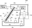
- FIG. 12 is a schematic diagram showing a first example of the artificial photosynthesis apparatus according to the embodiment of the present invention.
- An artificial photosynthesis apparatus 100 shown in FIG. 12 is connected to, for example, an artificial photosynthesis module 10 that decomposes water as a raw material fluid to obtain a fluid such as a gas, a tank 102 that stores water, and the tank 102 and the artificial photosynthesis module 10.
- the artificial light synthesizing modules 10 are arranged with the direction D and the direction W parallel to each other and arranged in a direction M orthogonal to the direction W. Since the configuration of the artificial photosynthesis module 10 is the same as the configuration shown in FIG. 1, detailed description thereof is omitted.
- the number of artificial photosynthesis modules 10 is not particularly limited as long as it is plural, and it is sufficient that there are at least two.
- the tank 102 stores water as a raw material fluid as described above.
- water supplied to the artificial photosynthesis module 10 is stored, and water discharged from the artificial photosynthesis module 10 through the discharge pipes 28a and 28b.
- the raw material fluid such as is also stored.
- the tank 102 is not particularly limited as long as it can store a raw fluid such as water.
- the pump 104 is connected to the tank 102 via the pipe 103, and supplies a raw material fluid such as water stored in the tank 102 to the artificial photosynthesis module 10.
- the pump 104 also supplies a raw material fluid such as water discharged from the artificial photosynthesis module 10 and stored in the tank 102 to the artificial photosynthesis module 10.
- the pump 104 circulates a raw material fluid such as water between the tank 102 and the artificial photosynthesis module 10 via the supply pipes 26a and 26b and the discharge pipes 28a and 28b.
- the pump 104 is not particularly limited as long as a raw material fluid such as water can be circulated between the tank 102 and the artificial photosynthesis module 10. Is appropriately selected based on the above.
- the gas recovery unit 105 recovers the obtained hydrogen gas, for example, generated by the artificial gas synthesis module 10 and the oxygen gas recovery unit 106 that recovers the obtained oxygen gas, for example, generated by the artificial photosynthesis module 10. And a hydrogen gas recovery unit 108.
- the oxygen gas recovery unit 106 is connected to the artificial photosynthesis module 10 via an oxygen tube 107.
- the configuration of the oxygen gas recovery unit 106 is not particularly limited as long as the obtained gas or liquid fluid such as oxygen gas can be recovered.
- an apparatus using an adsorption method is used. Can do.
- the hydrogen gas recovery unit 108 is connected to the artificial photosynthesis module 10 through a hydrogen pipe 109.
- the configuration of the hydrogen gas recovery unit 108 is not particularly limited as long as the obtained gas or liquid fluid such as hydrogen gas can be recovered.
- an apparatus using an adsorption method, a diaphragm method, or the like Can be used.
- the artificial photosynthesis module 10 may be tilted with respect to the direction W. In this case, the artificial photosynthesis module 10 shown in FIG. 7 is used. By tilting the artificial photosynthesis module 10, it becomes easier for water to move toward the tank 102, the efficiency of generation of oxygen gas and hydrogen gas can be increased, and the generated oxygen gas is transferred to the oxygen pipe 107 side with hydrogen. The gas easily moves to the hydrogen pipe 109 side, and oxygen gas and hydrogen gas can be efficiently recovered.
- the artificial photosynthesis module 10 is not limited to the one shown in FIG. 1, and the artificial photosynthesis module 60 shown in FIG. 8, the artificial photosynthesis module 60 shown in FIG. 9, and the artificial photosynthesis module 70 shown in FIG. it can.
- the hydrogen gas recovery unit 108 and the oxygen gas recovery unit 106 are provided on the pump 104 side, the present invention is not limited to this and may be provided on the tank 102 side.
- the artificial photosynthesis apparatus 100 when a constant current is supplied to the oxygen generation electrode 12 and the hydrogen generation electrode 14 of the artificial photosynthesis module 10 using a potentiostat, oxygen is generated from the oxygen generation electrode 12 and hydrogen is generated from the hydrogen generation electrode. .
- Oxygen and hydrogen are stored as gases in the upper part of the artificial photosynthesis module 10, oxygen is recovered in the oxygen gas recovery unit 106, and hydrogen is recovered in the hydrogen gas recovery unit 108.
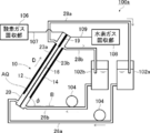
- FIG. 13 is a schematic diagram showing a second example of the artificial photosynthesis apparatus according to the embodiment of the present invention
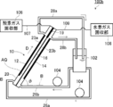
- FIG. 14 is a schematic diagram showing a third example of the artificial photosynthesis apparatus according to the embodiment of the present invention.
- These are the schematic diagrams which show the 4th example of the artificial photosynthesis apparatus of embodiment of this invention. 13 to 15, the same components as those of the artificial light synthesizing module 10 shown in FIG. 1 and the artificial light synthesizing device 100 shown in FIG. 12 are denoted by the same reference numerals, and detailed description thereof will be omitted.
- the artificial photosynthesis apparatus 100a shown in FIG. 13 is provided with an oxygen tube 107 in the first section 23a, and an oxygen gas recovery unit 106 is connected to the oxygen pipe 107. ing.
- a hydrogen pipe 109 is provided in the second compartment 23 b, and a hydrogen gas recovery unit 108 is connected to the hydrogen pipe 109.
- the discharge pipe 28a is connected to the first tank 102a, and the discharge pipe 28b is connected to the second tank 102b.
- the first tank 102a and the first compartment 23a are connected by a supply pipe 26a.
- a pump 104 is provided in the supply pipe 26a. Water AQ stored in the first tank 102a is supplied to the first compartment 23a by the pump 104.
- the second tank 102b and the second compartment 23b are connected by a supply pipe 26b.
- a pump 104 is provided in the supply pipe 26b. Water AQ stored in the second tank 102b is supplied to the second compartment 23b by the pump 104.
- water AQ is supplied in the direction D.
- a partition wall 19 is provided instead of the diaphragm 16 on the oxygen tube 107 and hydrogen tube 109 side in the container 20.
- the partition wall 19 is configured not to allow gas to permeate, and mixing of hydrogen and oxygen generated in the container 20 is suppressed.
- the artificial photosynthesis module 10 is disposed with an inclination of 45 ° with respect to the horizontal plane B.
- the artificial photosynthesis device 100a when a constant current is supplied to the oxygen generation electrode 12 and the hydrogen generation electrode 14 of the artificial photosynthesis module 10 using a potentiostat, oxygen is generated from the oxygen generation electrode 12 and hydrogen is generated from the hydrogen generation electrode. .
- Oxygen and hydrogen accumulate in the upper part of the artificial photosynthesis module 10 as gas, mixing of hydrogen and oxygen is suppressed by the partition wall 19, oxygen is recovered by the oxygen gas recovery unit 106, and hydrogen is recovered by the hydrogen gas recovery unit 108. .
- the artificial photosynthesis apparatus 100b shown in FIG. 14 is provided with an oxygen pipe 107 in the first section 23a, and an oxygen gas recovery unit 106 is connected to the oxygen pipe 107. ing.
- a hydrogen pipe 109 is provided in the second compartment 23 b, and a hydrogen gas recovery unit 108 is connected to the hydrogen pipe 109.
- the discharge pipe 28 a and the discharge pipe 28 b are connected to the tank 102.
- the artificial photosynthesis apparatus 100b shown in FIG. 14 has one tank 102.
- the tank 102 and the first compartment 23a are connected by a supply pipe 26a.
- a pump 104 is provided in the supply pipe 26a. Water AQ stored in the tank 102 is supplied to the first compartment 23a by the pump 104.
- the tank 102 and the second compartment 23b are connected by a supply pipe 26b.
- a pump 104 is provided in the supply pipe 26b. Water AQ stored in the tank 102 is supplied to the second compartment 23b by the pump 104.
- the difference in pH of the water AQ between the first compartment 23a and the second compartment 23b becomes uneven as time passes, and the uneven pH of the water AQ inevitably increases the electrolysis voltage, that is, the conversion efficiency decreases. Although it occurs, by using one tank 102, the deviation in pH of the water AQ can be suppressed, and the effect of suppressing the time-dependent increase in electrolytic voltage can be obtained.
- the artificial photosynthesis module 10 water AQ is supplied in the direction D.
- a partition wall 19 is provided instead of the diaphragm 16 on the oxygen tube 107 and hydrogen tube 109 side in the container 20.
- the partition wall 19 is configured not to allow gas to permeate, and mixing of hydrogen and oxygen generated in the container 20 is suppressed.
- the artificial photosynthesis module 10 is disposed with an inclination of 45 ° with respect to the horizontal plane B.
- oxygen is generated from the oxygen generation electrode 12 and hydrogen is generated from the hydrogen generation electrode.
- Oxygen and hydrogen accumulate in the upper part of the artificial photosynthesis module 10 as gas, mixing of hydrogen and oxygen is suppressed by the partition wall 19, oxygen is recovered by the oxygen gas recovery unit 106, and hydrogen is recovered by the hydrogen gas recovery unit 108.
- the artificial photosynthesis apparatus 100 c shown in FIG. 15 is provided with an oxygen pipe 107 in the first section 23 a, and an oxygen gas recovery unit 106 is connected to the oxygen pipe 107. ing.
- a hydrogen pipe 109 is provided in the second compartment 23 b, and a hydrogen gas recovery unit 108 is connected to the hydrogen pipe 109.
- the discharge pipe 28a is connected to the first tank 102a, and the discharge pipe 28b is connected to the second tank 102b.
- the first tank 102a and the first compartment 23a are connected by a supply pipe 26a.
- a pump 104 is provided in the supply pipe 26a. Water AQ stored in the first tank 102a is supplied to the first compartment 23a by the pump 104.
- the second tank 102b and the second compartment 23b are connected by a supply pipe 26b.
- a pump 104 is provided in the supply pipe 26b. Water AQ stored in the second tank 102b is supplied to the second compartment 23b by the pump 104.
- water AQ is supplied in the direction D.
- a partition wall 19 is provided instead of the diaphragm 16 on the oxygen tube 107 and hydrogen tube 109 side in the container 20.
- the partition wall 19 is configured not to allow gas to permeate, and mixing of hydrogen and oxygen generated in the container 20 is suppressed.
- the artificial photosynthesis module 10 is disposed with an inclination of 45 ° with respect to the horizontal plane B.
- the artificial photosynthesis apparatus 100c when a constant current is supplied to the oxygen generation electrode 12 and the hydrogen generation electrode 14 of the artificial photosynthesis module 10 using a potentiostat, oxygen is generated from the oxygen generation electrode 12 and hydrogen is generated from the hydrogen generation electrode. .
- Oxygen and hydrogen accumulate in the upper part of the artificial photosynthesis module 10 as gas, mixing of hydrogen and oxygen is suppressed by the partition wall 19, oxygen is recovered by the oxygen gas recovery unit 106, and hydrogen is recovered by the hydrogen gas recovery unit 108.
- the artificial photosynthesis apparatus 100c may be configured with only one tank 102 as in the artificial photosynthesis apparatus 100b described above. As described above, by using one tank 102, it is possible to suppress the unevenness of the pH of the recovered water AQ and to obtain the effect of suppressing the time-dependent increase in the electrolytic voltage.
- the oxygen generating electrode 12 is provided with a through hole 12a
- the hydrogen generating electrode 14 is provided with a through hole 14a.
- a diaphragm 16 is disposed between the hydrogen generation electrode 12 and the oxygen generation electrode 14. Due to the through holes 12a and 14a, the generated bubbles escape to the opposite side of the electrodes and flow through the back of each electrode. As a result, air bubbles are sandwiched between the diaphragm 16 and the electrode, and the flow of water AQ and the flow of ions through the diaphragm 16 can be prevented and the electrolytic voltage can be prevented from rising.
- the electrolytic voltage can be lowered, that is, the conversion efficiency can be increased.
- the oxygen generation electrode does not need to be transparent, and a transparent electrode having high resistance such as an ITO (Indium Tin Oxide) film having high electrical resistance. The use of a film becomes unnecessary, and the electrolysis voltage can be further reduced.
- the inclination angle is set to 45 °.
- the inclination angle is not limited to this, and sunlight is efficiently used by inclining in the sunlight incident direction according to the latitude. be able to.
- the concentration of hydrogen that has passed through the diaphragm 16 and moved from the second compartment 23b to the first compartment 23a is defined as the hydrogen permeation concentration. Since hydrogen moved from the second section 23b to the first section 23a is regarded as an impurity for oxygen, the hydrogen permeation concentration is ideally 0%, but the upper limit is 4% or less. In order to increase the oxygen purity in the subsequent process, considering the oxygen generation efficiency, the hydrogen permeation concentration is practically preferably 2% or less, and if it is 2% or less, the decrease in oxygen generation efficiency is suppressed. .
- the concentration of oxygen that has passed through the diaphragm 16 and moved from the first compartment 23a to the second compartment 23b is defined as the oxygen transmission concentration. Since oxygen that has moved from the first section 23a to the second section 23b is regarded as an impurity for hydrogen, the oxygen transmission concentration is ideally 0%, but the upper limit is 4% or less. In order to increase the hydrogen purity in the subsequent process, considering the hydrogen generation efficiency, it is desirable that the oxygen permeation concentration is practically suppressed to 2% or less, and if it is 2% or less, the decrease in hydrogen generation efficiency is suppressed. . For this reason, when there is less mixing of oxygen and hydrogen, energy for obtaining high-purity oxygen and hydrogen can be reduced, and the generation efficiency of oxygen and hydrogen can be increased.
- the present invention is basically configured as described above. Although the artificial photosynthesis module and the artificial photosynthesis apparatus of the present invention have been described in detail above, the present invention is not limited to the above-described embodiment, and various improvements or modifications can be made without departing from the gist of the present invention. Of course it is good.
- a gas chromatography device includes oxygen generated from an oxygen generation electrode from the first compartment on the oxygen generation side and hydrogen that has passed through the diaphragm from the second compartment on the hydrogen generation side and permeated into the first compartment on the oxygen generation side. Is detected.
- the hydrogen permeation concentration was defined as the hydrogen permeation concentration when the concentration of hydrogen passing through and the amount of oxygen generated originally was 100%.
- the light transmittance of the diaphragm used in Example 1 and Comparative Example 1 was measured.
- Reference Example 1 does not use a diaphragm.
- the light transmittance was measured as follows. [Measurement of light transmittance]
- SH7000 manufactured by Nippon Denshoku Industries Co., Ltd. which is generally used, was used as a transmittance measuring device.
- the diaphragm was immersed in pure water and set in a transmittance measuring device to measure the light transmittance.
- the light transmittance was calculated by integrating all the light transmitted in the wavelength range of 380 nm to 780 nm with an integrating sphere as the transmitted light amount.
- the hydrogen generating electrode and the oxygen generating electrode are arranged in a container provided with the electrolytic aqueous solution inlet and the electrolytic aqueous solution outlet.
- a diaphragm was disposed between the hydrogen generating electrode and the oxygen generating electrode.
- the distance between the hydrogen generating electrode surface and the oxygen generating electrode surface, that is, the distance was set to 4 mm.
- the container was placed at an angle of 45 °.
- the electrolytic aqueous solution is allowed to flow in parallel with the hydrogen generating electrode surface and the oxygen generating electrode surface, and a honeycomb rectifying plate is further provided so that the flow of the electrolytic aqueous solution is above the hydrogen generating electrode surface and the oxygen generating electrode surface.
- a honeycomb rectifying plate is further provided so that the flow of the electrolytic aqueous solution is above the hydrogen generating electrode surface and the oxygen generating electrode surface.
- Example 1 In the artificial photosynthesis module of Example 1, the hydrogen generation electrode and the oxygen generation electrode are flat plates and are called solid electrodes.
- an electrode obtained by subjecting a surface of a flat titanium substrate having an electrode size of 100 mm ⁇ 100 mm to a platinum plating treatment with a thickness of 1 ⁇ m (Excelroad EA: Nippon Carlit Co., Ltd.)) was used.
- a PTFE membrane ADVANTEC H100A (product name) (film thickness: 35 ⁇ m (0.035 mm), average pore diameter: 1.0 ⁇ m)
- the diaphragm of Example 1 is hydrophilic and the film quality is a membrane.
- the aqueous electrolytic solution was flowed in the direction D shown in FIG. 1 at a flow rate of 1.0 liter / min.
- Comparative Example 1 In the artificial photosynthesis module of Comparative Example 1, a Teflon (registered trademark) fiber-reinforced Nafion (registered trademark) film (sigma-aldrich Nafion (registered trademark) 324 (product name) (film thickness: 152 ⁇ m (0.152 mm), average) The same configuration as in Example 1 was used except that a pore diameter of less than 0.001 ⁇ m and a fiber reinforced mesh) were used. The diaphragm of Comparative Example 1 is hydrophilic and the film quality is a membrane. For this reason, the detailed description is abbreviate
- the hydrogen generation electrode and the oxygen generation electrode of Comparative Example 1 have a configuration called a solid electrode.
- Reference Example 1 The artificial photosynthesis module of Reference Example 1 has the same configuration as that of Example 1 except that no diaphragm is used. For this reason, the detailed description is abbreviate
- the hydrogen generation electrode and the oxygen generation electrode of Reference Example 1 have a configuration called a solid electrode.
- the hydrogen permeation concentration and the oxygen permeation concentration were not measured.
- “mixing” is described.
- Example 1 had a lower electrolysis voltage and better energy conversion efficiency than Comparative Example 1.
- the generated hydrogen and oxygen are mixed, and it is necessary to separate the oxygen and hydrogen, resulting in poor conversion efficiency.
- the electrolysis voltage was about the same as in Reference Example 1.
- Example 2 is different from Example 1 above in that a PTFE membrane (Millipore Omnipore 1.0 (product name) (film thickness 85 ⁇ m (0.085 mm), average pore diameter 1.0 ⁇ m)) is used as the diaphragm.
- the same configuration as that of Example 1 was adopted.
- the diaphragm of Example 2 is hydrophilic and the film quality is a membrane.
- Example 3 is different from Example 1 described above except that a PTFE membrane (Millipore Omnipore 10 (product name) (film thickness 85 ⁇ m (0.085 mm), average pore diameter 10.0 ⁇ m)) is used as the diaphragm.
- Example 4 The configuration was the same as in Example 1.
- the diaphragm of Example 3 is hydrophilic and the film quality is a membrane.
- Example 4 is different from Example 1 described above except that a PTFE membrane (Millipore Omnipore 0.1 (product name) (film thickness 30 ⁇ m (0.030 mm), average pore diameter 0.1 ⁇ m)) is used as the diaphragm.
- the same configuration as that of Example 1 was adopted.
- the diaphragm of Example 4 is hydrophilic and the film quality is a membrane.
- Example 5 In Example 5, a PTFE membrane (Tobutsu Techno Co., Ltd.
- FP-100-100 (product name) (film thickness: 100 ⁇ m (0.100 mm), average pore diameter: 3.2 ⁇ m)) is used as a diaphragm as compared with Example 1 described above.
- the configuration was the same as in Example 1 except for the points used.
- the diaphragm of Example 5 is obtained by hydrophilizing hydrophobicity, and the film quality is porous.
- the method shown in WO2014 / 21167 was used.
- Comparative Example 2 uses a PET film (YUASA MF-250BN (product name) (film thickness: 170 ⁇ m (0.170 mm), average pore diameter: 2.5 ⁇ m)) as a diaphragm as compared with Example 1 described above. Except for this, the configuration was the same as in Example 1.
- the diaphragm of Comparative Example 2 is obtained by hydrophobizing hydrophobicity, and the film quality is nonwoven paper. For the hydrophilic treatment, the method shown in WO2014 / 21167 was used.
- Comparative Example 3 In Comparative Example 3, as compared with Example 1 described above, a PET film (SEFER Co., Ltd.
- PET51-HD product name (film thickness 60 ⁇ m (0.060 mm), average pore diameter less than 50.0 ⁇ m)) is used as a diaphragm.
- the configuration is the same as that of Example 1, except that The diaphragm of Comparative Example 3 is obtained by hydrophilizing hydrophobicity, and the film quality is mesh.
- the method shown in WO2014 / 21167 was used. “> 4.0” in the column of oxygen transmission concentration shown in Table 2 below indicates that the oxygen transmission concentration exceeds 4.0%.
- Comparative Example 4 Comparative Example 4 was different from Example 1 described above except that a PTFE membrane (Futamura Chemical Cellophane (product name) (thickness 22 ⁇ m (0.022 mm), average pore diameter less than 0.1 ⁇ m)) was used as the diaphragm.
- the configuration was the same as in Example 1.
- the membrane of Comparative Example 4 is hydrophilic and the film quality is a membrane.
- Examples 2 to 4 have the same configuration except that the thickness and the average pore diameter are different. From Examples 2 to 4, it was confirmed that the electrolytic voltage was practical at least when the average pore size was 0.1 ⁇ m to 10.0 ⁇ m and the film thickness was 35 ⁇ m to 85 ⁇ m or less. In Examples 2 to 4, the oxygen permeation concentration and the hydrogen permeation concentration of oxygen passing through the diaphragm and passing through to the opposite side are less than 2%, which is practical for increasing the purity in the subsequent process. It was confirmed that. In Example 5, the hydrophilic treatment was performed, but the light transmittance could be 90% or more, and the electrolysis voltage could be 3.0V or less and the hydrogen permeability could be 2% or less.
- Comparative Example 2 has low light transmittance, high electrolytic voltage after 10 minutes, and poor conversion efficiency.
- Comparative Example 3 the average pore size was large, the hydrogen permeation concentration was as high as 3.29%, and the oxygen permeation concentration was as high as over 4.0%, which was unsuitable for practical performance.
- Comparative Example 4 the electrolysis voltage after 10 minutes is high and the conversion efficiency is poor.
- Example 6 uses the artificial photosynthesis apparatus having the configuration shown in FIG. 13, and Example 7 uses the artificial photosynthesis apparatus having the configuration shown in FIG.
- Example 6 and Example 7 the electrolysis voltage was measured after 10 minutes, 20 minutes, 60 minutes, and 120 minutes. The results are shown in Table 3 below.
- the electrolytic voltage was measured by using a 1M Na 2 SO 4 electrolytic solution as the electrolytic aqueous solution, flowing the electrolytic aqueous solution in the direction D shown in FIGS. 13 and 14, and the flow rate of the electrolytic aqueous solution being 4.2 cm / second. Except for certain points, the second embodiment is the same as the first embodiment, and a detailed description thereof will be omitted.
- Example 6 Example 6 was the same as Example 1 except that the electrolyte solution was separately circulated between the oxygen generation electrode and the hydrogen generation electrode, as compared to Example 1.
- Example 7 has the same configuration as Example 1 except that the electrolyte solution was collected and circulated in a single tank using an oxygen generation electrode and a hydrogen generation electrode, as compared to Example 1. .
- Example 7 As shown in Table 3, in the separation circulation method of Example 6 and the mixing circulation method of Example 7, the electrolytic voltage is maintained lower in the mixed circulation method of Example 7 after 60 minutes or more have elapsed. That is, the conversion efficiency of Example 7 is maintained higher.
- the diaphragm since the oxygen generating electrode and the hydrogen generating electrode are partitioned by the diaphragm, the pH of the electrolytic aqueous solution in each section is biased with time. As a result, an increase in electrolytic voltage, that is, a reduction in conversion efficiency inevitably occurs.
- the mixed circulation system of Example 7 since the electrolytic aqueous solution collected in one tank is circulated and used, the uneven pH of the electrolytic aqueous solution in the tank is eliminated and the increase in electrolytic voltage with time is suppressed. Excellent effect.
- Example 8 having a flat electrode configuration called a solid electrode and Example 9 having a mesh electrode configuration.
- the results are shown in Table 4 below.
- the method of measuring the electrolytic voltage is that the electrolytic solution of 1M Na 2 SO 4 is used as the electrolytic aqueous solution, the electrolytic aqueous solution is flowed in the direction D shown in FIG. 15, and the flow rate of the electrolytic aqueous solution is 4.2 cm / second. Since this is the same as the first embodiment described above, a detailed description thereof will be omitted.
- Example 8 and Example 9 will be described.
- the eighth embodiment has the same configuration as the first embodiment.
- an artificial photosynthesis apparatus having the configuration shown in FIG. 13 was used.
- Example 9 Example 9 is different from Example 1 except that the oxygen generation electrode and the hydrogen generation electrode were made of a mesh electrode configuration in which platinum wires having a diameter of 0.08 mm were knitted at a density of 80 wires / inch. The configuration was the same as in Example 1.
- an artificial photosynthesis apparatus having the configuration shown in FIG. 15 was used.
- Example 9 having a mesh electrode configuration was able to maintain an electrolytic voltage equivalent to that of Example 8, and was able to maintain high conversion efficiency.
- Example 9 due to the through holes of the oxygen generation electrode and the hydrogen generation electrode, the generated bubbles escape to the opposite electrode and flow through the back of the electrode.
- bubbles are sandwiched between the diaphragm and the electrode, and the flow of the electrolyte and the flow of ions through the diaphragm are prevented, and the electrolytic voltage is suppressed from increasing.
- the electrolytic voltage can be lowered, that is, the conversion efficiency can be increased.
- the oxygen generation electrode since sunlight passes through the through hole of the oxygen generation electrode to the hydrogen generation electrode, the oxygen generation electrode does not need to be transparent, and a transparent electrode film such as ITO (Indium Tin Oxide) with high electrical resistance is used. It becomes unnecessary and the electrolytic voltage can be further lowered.
- ITO Indium Tin Oxide
Landscapes
- Chemical & Material Sciences (AREA)
- Engineering & Computer Science (AREA)
- Metallurgy (AREA)
- Chemical Kinetics & Catalysis (AREA)
- Electrochemistry (AREA)
- Materials Engineering (AREA)
- Organic Chemistry (AREA)
- Inorganic Chemistry (AREA)
- Electrolytic Production Of Non-Metals, Compounds, Apparatuses Therefor (AREA)
- Catalysts (AREA)
- Oxygen, Ozone, And Oxides In General (AREA)
- Electrodes For Compound Or Non-Metal Manufacture (AREA)
- Life Sciences & Earth Sciences (AREA)
- Sustainable Development (AREA)
- Sustainable Energy (AREA)
Abstract
エネルギー変換効率が優れた人工光合成モジュール及び人工光合成装置を提供する。人工光合成モジュールは光により原料流体を分解して第1の流体を得る、第1の電極と、光により原料流体を分解して第2の流体を得る、第2の電極と、第1の電極と第2の電極の間に設けられた隔膜とを有する、人工光合成モジュールであって、隔膜は、貫通孔を有する膜で構成され、且つ、温度25℃の純水に1分浸漬させ、純水に浸漬された状態において、波長380nm~780nmの波長域の光透過率が60%以上であり、隔膜の貫通孔の平均孔径は、0.1μm超50μm未満である。人工光合成装置は上述の人工光合成モジュールを有する。
Description
本発明は、光により原料流体を分解して第1の流体を得る、第1の電極と、光により原料流体を分解して第2の流体を得る、第2の電極とを有する人工光合成モジュール及び人工光合成装置に関し、特に第1の電極と第2の電極の間に、多孔質膜で構成され、且つ水に浸漬された状態で透明な隔膜が配置された人工光合成モジュール及び人工光合成装置に関する。
現在、光触媒を用い、再生可能なエネルギーである太陽光エネルギーを利用して水を分解し、水素ガス及び酸素ガス等の気体を得ることがなされている。
例えば、特許文献1には、可視光応答性光触媒、レドックス媒体及び対極含む水素生成セルと、半導体電極を有する酸素生成セルと、対極と半導体電極を導通する手段とを備えた水素及び酸素の製造装置が記載されている。特許文献1では、水素生成セルと酸素生成セルがイオン交換膜で連通されている。イオン交換膜として、ナフィオン(登録商標)が例示されている。
例えば、特許文献1には、可視光応答性光触媒、レドックス媒体及び対極含む水素生成セルと、半導体電極を有する酸素生成セルと、対極と半導体電極を導通する手段とを備えた水素及び酸素の製造装置が記載されている。特許文献1では、水素生成セルと酸素生成セルがイオン交換膜で連通されている。イオン交換膜として、ナフィオン(登録商標)が例示されている。
特許文献1の水素及び酸素の製造装置では、電極に貫通孔を設けることなく、水素生成セルと酸素生成セルと導通をさせ、その間にイオン交換膜を挿入している。この場合、酸素生成セルで発生したイオンの電解液中の移動量が大きくなるため、エネルギー変換効率が下がる。
また、特許文献1のようにイオン交換膜にナフィオン(登録商標)を用いた場合、イン移動効率が低下し、過電圧が上昇する。また、ナフィオン(登録商標)は、プロトン及びイオンを伝導させるものであり、しかも高分子電解質であり、多孔質ではないため、電解液を移動させることはできない。このため、ナフィオン(登録商標)では、プロトン及びイオンは電解液と共に抵抗なく移動できず、移動抵抗が発生する。これにより、エネルギー変換効率が下がる。
また、上述の移動抵抗を抑制するために電極に貫通孔を設けた場合、貫通孔が大きいと、発生した酸素と水素とが混合し、発生した酸素と水素について、高い純度での回収が困難になる。このことから、酸素及び水素の生成効率も低下する。
また、特許文献1のようにイオン交換膜にナフィオン(登録商標)を用いた場合、イン移動効率が低下し、過電圧が上昇する。また、ナフィオン(登録商標)は、プロトン及びイオンを伝導させるものであり、しかも高分子電解質であり、多孔質ではないため、電解液を移動させることはできない。このため、ナフィオン(登録商標)では、プロトン及びイオンは電解液と共に抵抗なく移動できず、移動抵抗が発生する。これにより、エネルギー変換効率が下がる。
また、上述の移動抵抗を抑制するために電極に貫通孔を設けた場合、貫通孔が大きいと、発生した酸素と水素とが混合し、発生した酸素と水素について、高い純度での回収が困難になる。このことから、酸素及び水素の生成効率も低下する。
本発明の目的は、前述の従来技術に基づく問題点を解消し、エネルギー変換効率が優れた人工光合成モジュール及び人工光合成装置を提供することにある。
上述の目的を達成するために、本発明は、光により原料流体を分解して第1の流体を得る、第1の電極と、光により原料流体を分解して第2の流体を得る、第2の電極と、第1の電極と第2の電極の間に設けられた隔膜とを有する、人工光合成モジュールであって、隔膜は、貫通孔を有する膜で構成され、且つ、温度25℃の純水に1分浸漬させ、純水に浸漬された状態において、波長380nm~780nmの波長域の光透過率が60%以上であり、隔膜の貫通孔の平均孔径は、0.1μm超50μm未満であることを特徴とする、人工光合成モジュールを提供するものである。
隔膜は、親水性表面を有する多孔質膜で構成されることが好ましい。
第1の電極は、第1の基板と、第1の基板上に設けられた第1の導電層と、第1の導電層上に設けられた第1の光触媒層と、第1の光触媒層の少なくとも一部に担持された第1の助触媒とを有し、第2の電極は、第2の基板と、第2の基板上に設けられた第2の導電層と、第2の導電層上に設けられた第2の光触媒層と、第2の光触媒層の少なくとも一部に担持された第2の助触媒とを有し、第1の電極と隔膜と第2の電極が、光の進行方向に沿って直列に配置されていることが好ましい。
光が第1の電極側から入射され、且つ、第1の電極が有する第1の基板が透明であることが好ましい。
また、第1の電極と第2の電極とは、複数の貫通孔を有し、隔膜は、第1の電極と第2の電極と間に配置されて挟まれていることが好ましい。
第1の流体は気体又は液体であり、第2の流体は気体又は液体であることが好ましい。
原料流体が水であり、第1の流体が酸素であり、第2の流体が水素であることが好ましい。
第1の電極は、第1の基板と、第1の基板上に設けられた第1の導電層と、第1の導電層上に設けられた第1の光触媒層と、第1の光触媒層の少なくとも一部に担持された第1の助触媒とを有し、第2の電極は、第2の基板と、第2の基板上に設けられた第2の導電層と、第2の導電層上に設けられた第2の光触媒層と、第2の光触媒層の少なくとも一部に担持された第2の助触媒とを有し、第1の電極と隔膜と第2の電極が、光の進行方向に沿って直列に配置されていることが好ましい。
光が第1の電極側から入射され、且つ、第1の電極が有する第1の基板が透明であることが好ましい。
また、第1の電極と第2の電極とは、複数の貫通孔を有し、隔膜は、第1の電極と第2の電極と間に配置されて挟まれていることが好ましい。
第1の流体は気体又は液体であり、第2の流体は気体又は液体であることが好ましい。
原料流体が水であり、第1の流体が酸素であり、第2の流体が水素であることが好ましい。
本発明は、原料流体を分解して流体を得る人工光合成モジュール、原料流体を貯蔵するタンク、タンクと人工光合成モジュールに接続され、人工光合成モジュールに原料流体を供給する供給管、タンクと人工光合成モジュールに接続され、人工光合成モジュールから原料流体を回収する排出管、原料流体を供給管と排出管を介してタンクと人工光合成モジュールとの間で循環させるポンプ、及び人工光合成モジュールで得られた流体を回収するガス回収部、を有する、人工光合成装置であって、光により原料流体を分解して第1の流体を得る、第1の基板と、第1の基板上に設けられた第1の導電層と、第1の導電層上に設けられた第1の光触媒層と、第1の光触媒層の少なくとも一部に担持された第1の助触媒とを有する第1の電極と、光により原料流体を分解して第2の流体を得る、第2の基板と、第2の基板上に設けられた第2の導電層と、第2の導電層上に設けられた第2の光触媒層と、第2の光触媒層の少なくとも一部に担持された第2の助触媒とを有する第2の電極と、第1の電極と第2の電極の間に設けられた隔膜とを具備し、第1の電極と第2の電極は、互いに導線を介して電気的に接続されており、隔膜は、貫通孔を有する膜で構成され、且つ、温度25℃の純水に1分浸漬させ、純水に浸漬された状態において、波長380nm~780nmの波長域の光透過率が60%以上であり、隔膜貫通孔の平均孔径は、0.1μm超50μm未満である人工光合成モジュールが複数配置されていることを特徴とする、人工光合成装置を提供するものである。
人工光合成モジュールは隔膜で区画された、第1の電極が設けられた第1の区画と、第2の電極が設けられた第2の区画とを有し、供給管は、第1の区画及び第2の区画に原料流体を供給し、排出管は、第1の区画及び第2の区画の原料流体を回収し、原料流体を貯蔵するタンクは、人工光合成モジュールの第1の区画の原料流体、及び第2の区画の原料流体が、混合されて貯蔵され、タンクに混合されて貯蔵された原料流体が、ポンプにより供給管を介して第1の区画及び第2の区画に原料流体を供給されることが好ましい。
第1の流体は気体又は液体であり、第2の流体は気体又は液体であることが好ましい。
原料流体が水であり、第1の流体が酸素であり、第2の流体が水素であることが好ましい。
第1の流体は気体又は液体であり、第2の流体は気体又は液体であることが好ましい。
原料流体が水であり、第1の流体が酸素であり、第2の流体が水素であることが好ましい。
本発明によれば、エネルギー変換効率が優れたものとすることができる。
以下に、添付の図面に示す好適実施形態に基づいて、本発明の人工光合成モジュール及び人工光合成装置を詳細に説明する。
なお、以下において数値範囲を示す「~」とは両側に記載された数値を含む。例えば、εが数値α1~数値β1とは、εの範囲は数値α1と数値β1を含む範囲であり、数学記号で示せばα1≦ε≦β1である。
「平行」及び「垂直」を含め角度については、特に断りがなければ、技術分野で一般的に許容される誤差範囲を含むものとする。
なお、以下において数値範囲を示す「~」とは両側に記載された数値を含む。例えば、εが数値α1~数値β1とは、εの範囲は数値α1と数値β1を含む範囲であり、数学記号で示せばα1≦ε≦β1である。
「平行」及び「垂直」を含め角度については、特に断りがなければ、技術分野で一般的に許容される誤差範囲を含むものとする。
本発明の人工光合成モジュールは、分解対象となる原料流体を、光エネルギーを利用して分解して、原料流体とは別の物質を得るものであり、光により原料流体を分解して第1の流体と第2の流体を得るものである。
人工光合成モジュールは、光により原料流体を分解して第1の流体を得る第1の電極と、光により原料流体を分解して第2の流体を得る第2の電極とを有する。
なお、第1の流体と第2の流体は、それぞれ流体であれば、特に限定されるものではなく、気体又は液体である。なお、上述の別の物質とは、原料流体を酸化又は還元して得らえる物質のことである。
以下、人工光合成モジュール及び人工光合成装置について説明する。
人工光合成モジュールは、光により原料流体を分解して第1の流体を得る第1の電極と、光により原料流体を分解して第2の流体を得る第2の電極とを有する。
なお、第1の流体と第2の流体は、それぞれ流体であれば、特に限定されるものではなく、気体又は液体である。なお、上述の別の物質とは、原料流体を酸化又は還元して得らえる物質のことである。
以下、人工光合成モジュール及び人工光合成装置について説明する。
原料流体が水であり、第1の流体が酸素であり、第2の流体が水素である場合を例にして、人工光合成モジュールを説明する。
図1は本発明の実施形態の人工光合成モジュールの第1の例を示す模式的断面図であり、図2は本発明の実施形態の人工光合成モジュールの第1の例を示す模式的平面図である。図3は酸素発生電極の一例を示す模式的断面図であり、図4は水素発生電極の一例を示す模式的断面図である。図5は隔膜を示す模式的斜視図である。
図1に示す人工光合成モジュール10は、例えば、光Lにより、原料流体である水AQを分解して、第1の流体である酸素と、第2の流体である水素を発生させる等して得るものである。人工光合成モジュール10は、例えば、酸素発生電極12と、水素発生電極14と、酸素発生電極12と水素発生電極14の間に設けられた隔膜16とを有する。人工光合成モジュール10は、酸素発生電極12と水素発生電極14を有する2電極水分解モジュールであり、例えば、酸素発生電極12と水素発生電極14は水AQに浸漬された状態で水AQの分解に利用される。
図1は本発明の実施形態の人工光合成モジュールの第1の例を示す模式的断面図であり、図2は本発明の実施形態の人工光合成モジュールの第1の例を示す模式的平面図である。図3は酸素発生電極の一例を示す模式的断面図であり、図4は水素発生電極の一例を示す模式的断面図である。図5は隔膜を示す模式的斜視図である。
図1に示す人工光合成モジュール10は、例えば、光Lにより、原料流体である水AQを分解して、第1の流体である酸素と、第2の流体である水素を発生させる等して得るものである。人工光合成モジュール10は、例えば、酸素発生電極12と、水素発生電極14と、酸素発生電極12と水素発生電極14の間に設けられた隔膜16とを有する。人工光合成モジュール10は、酸素発生電極12と水素発生電極14を有する2電極水分解モジュールであり、例えば、酸素発生電極12と水素発生電極14は水AQに浸漬された状態で水AQの分解に利用される。
人工光合成モジュール10は、酸素発生電極12、水素発生電極14及び隔膜16を収納する容器20を有する。容器20は、例えば、水平面B上に配置されている。
酸素発生電極12は、水AQに浸漬された状態で水AQを分解して酸素ガスを発生させるものであり、例えば、図2に示すように全体が平板状である。
水素発生電極14は、水AQに浸漬された状態で水AQを分解して水素ガスを発生させるものであり、例えば、図2に示すように全体が平板状である。
酸素発生電極12は、水AQに浸漬された状態で水AQを分解して酸素ガスを発生させるものであり、例えば、図2に示すように全体が平板状である。
水素発生電極14は、水AQに浸漬された状態で水AQを分解して水素ガスを発生させるものであり、例えば、図2に示すように全体が平板状である。
図1に示すように容器20は、一面が解放された筐体22と、筐体22の解放部分を覆う透明部材24を有する。隔膜16により、容器20内は、透明部材24側の第1の区画23aと、底面22b側の第2の区画23bに区画される。光Lは、例えば、太陽光であり、透明部材24側から入射される。透明部材24についても、後述の透明の規定を満たすことが好ましい。
酸素発生電極12と水素発生電極14とは、例えば、導線18により電気的に接続されている。且つ酸素発生電極12と水素発生電極14とは、光Lの進行方向Diに沿って直列に容器20内で隔膜16を挟んで、酸素発生電極12と水素発生電極14の順に配置されている。図1では、酸素発生電極12と水素発生電極14とが、隙間をあけて互いに平行にして重ねて配置されている。
酸素発生電極12と水素発生電極14とは、例えば、導線18により電気的に接続されている。且つ酸素発生電極12と水素発生電極14とは、光Lの進行方向Diに沿って直列に容器20内で隔膜16を挟んで、酸素発生電極12と水素発生電極14の順に配置されている。図1では、酸素発生電極12と水素発生電極14とが、隙間をあけて互いに平行にして重ねて配置されている。
酸素発生電極12と水素発生電極14の隙間Wdは、1mm~20mmが好ましく、隙間は小さい方が、エネルギー変換効率が良くなる。なお、酸素発生電極12と水素発生電極14の隙間Wdは、酸素発生電極12の第1の光触媒層34の表面34aと、水素発生電極14の第2の光触媒層44の表面44aの距離である。
第1の区画23aに酸素発生電極12が配置されており、第1の区画23a内で酸素ガスが発生される。第2の区画23bに第2の基板40が底面22bに接して、水素発生電極14が配置されており、第2の区画23b内に水素ガスが発生される。
なお、光Lは容器20に対して透明部材24側から、すなわち、光Lは酸素発生電極12側から入射される。上述の光Lの進行方向Diは透明部材24の表面24aに垂直な方向である。
なお、光Lは容器20に対して透明部材24側から、すなわち、光Lは酸素発生電極12側から入射される。上述の光Lの進行方向Diは透明部材24の表面24aに垂直な方向である。
第1の区画23aでは、第1の壁面22cに供給管26aが設けられ、第1の壁面22cと対向する第2の壁面22dに排出管28aが設けられている。第2の区画23bでは、第1の壁面22cに供給管26bが設けられ、第1の壁面22cと対向する第2の壁面22dに排出管28bが設けられている。供給管26aと供給管26bから水AQが容器20内に供給されて容器20内が水AQで満たされ、水AQは方向Dに流れ、排出管28aから酸素を含む水AQが排出され、酸素が回収される。排出管28bから水素を含む水AQが排出され、水素が回収される。この場合、水AQの流れ方向FAは方向Dである。
方向Dは第1の壁面22cから第2の壁面22dに向かう方向である。なお、筐体22は、例えば、水素発生電極14及び酸素発生電極12を使用した際に、短絡等が発生しない程度の電気絶縁性材料で構成される。筐体22は、例えば、アクリル樹脂で構成される。容器20は、後述の第1の基板30における透明の規定を満たすことが好ましい。
方向Dは第1の壁面22cから第2の壁面22dに向かう方向である。なお、筐体22は、例えば、水素発生電極14及び酸素発生電極12を使用した際に、短絡等が発生しない程度の電気絶縁性材料で構成される。筐体22は、例えば、アクリル樹脂で構成される。容器20は、後述の第1の基板30における透明の規定を満たすことが好ましい。
水AQには、蒸留水、及び冷却塔等で用いられる冷却水が含まれる。また、水AQには電解水溶液も含まれる。ここで、電解水溶液とは、H2Oを主成分とする液体であり、水を溶媒とし溶質を含む水溶液であってもよく、例えば、強アルカリ(KOH(水酸化カリウム))、H2SO4を含む電解液、又は硫酸ナトリウム電解液、リン酸カリウム緩衝液等である。電解水溶液としては、pH(水素イオン指数)9.5に調整したH3BO3が好ましい。
なお、人工光合成モジュール10では、水AQを供給するための供給部(図示せず)と、人工光合成モジュール10から排出される水AQを回収する回収部(図示せず)とを設けてもよい。
供給部には、ポンプ等の公知の水の供給装置が利用可能であり、回収部にはタンク等の公知の水の回収装置が利用可能である。
供給部は供給管26a、26bを介して人工光合成モジュール10に接続し、回収部は排出管28a、28bを介して人工光合成モジュール10に接続して、回収部で回収された水AQを供給部に循環させて、水AQを再利用することもできる。
また、水AQを隔膜16の表面16a(図5参照)及び裏面16b(図5参照)に対して平行に流し、水AQの流れを電極表面の上で層流にする。この場合、更にハニカム整流板を設けてもよい。水AQの流れは、乱流を含まず、水AQの流れ方向FAの流れにも乱流は含まれない。
供給部には、ポンプ等の公知の水の供給装置が利用可能であり、回収部にはタンク等の公知の水の回収装置が利用可能である。
供給部は供給管26a、26bを介して人工光合成モジュール10に接続し、回収部は排出管28a、28bを介して人工光合成モジュール10に接続して、回収部で回収された水AQを供給部に循環させて、水AQを再利用することもできる。
また、水AQを隔膜16の表面16a(図5参照)及び裏面16b(図5参照)に対して平行に流し、水AQの流れを電極表面の上で層流にする。この場合、更にハニカム整流板を設けてもよい。水AQの流れは、乱流を含まず、水AQの流れ方向FAの流れにも乱流は含まれない。
以下、人工光合成モジュール10の各部について説明する。
酸素発生電極12は、図1及び図3に示すように第1の基板30と、第1の基板30上、すなわち、表面30aに設けられた第1の導電層32と、第1の導電層32上、すなわち、表面32aに設けられた第1の光触媒層34と、第1の光触媒層34の少なくとも一部に担持された第1の助触媒36とを有する。酸素発生電極12が第1の電極である。
第1の助触媒36は、例えば、複数の助触媒粒子37で構成されている。これにより、第1の光触媒層34の表面34aへの光Lの入射光量の低下が抑制される。酸素発生電極12では、第1の助触媒36は第1の光触媒層34に接しているか、又は正孔が移動できる層を介在して存在し、水AQと接していることが必要である。
第1の光触媒層34の吸収端は、例えば、400nm~800nm程度である。
ここで、吸収端とは、連続吸収スペクトルにおいて波長がこれ以上長くなると吸収率が急激に減少するようになる部分又はその端のことであり、吸収端の単位はnmである。酸素発生電極12は、全体の厚みが2mm程度であることが好ましい。
酸素発生電極12は、図1及び図3に示すように第1の基板30と、第1の基板30上、すなわち、表面30aに設けられた第1の導電層32と、第1の導電層32上、すなわち、表面32aに設けられた第1の光触媒層34と、第1の光触媒層34の少なくとも一部に担持された第1の助触媒36とを有する。酸素発生電極12が第1の電極である。
第1の助触媒36は、例えば、複数の助触媒粒子37で構成されている。これにより、第1の光触媒層34の表面34aへの光Lの入射光量の低下が抑制される。酸素発生電極12では、第1の助触媒36は第1の光触媒層34に接しているか、又は正孔が移動できる層を介在して存在し、水AQと接していることが必要である。
第1の光触媒層34の吸収端は、例えば、400nm~800nm程度である。
ここで、吸収端とは、連続吸収スペクトルにおいて波長がこれ以上長くなると吸収率が急激に減少するようになる部分又はその端のことであり、吸収端の単位はnmである。酸素発生電極12は、全体の厚みが2mm程度であることが好ましい。
酸素発生電極12は、水素発生電極14に光Lを入射させるために、光Lが透過可能なものである。光Lを水素発生電極14に照射させるためには、光Lが酸素発生電極12を透過する必要があり、第1の基板30は透明である。水素発生電極14は、後述する第2の基板40(図4参照)が透明である必要がない。
第1の基板30において透明とは、第1の基板30の光透過率が、波長380nm~780nmの領域において、最低で60%である。上述の光透過率は分光光度計により測定される。分光光度計としては、例えば、紫外可視分光光度計である日本分光株式会社製V-770(品名)が用いられる。
なお、光透過率をT%とするとき、T=(Σλ(測定物質+基板)/Σλ(基板))×100%で表される。上述の測定物質はガラス基板で、基板リファレンスは空気である。積分の範囲は波長380nm~780nmの光のうち、光触媒層の受光波長までとする。なお、光透過率の測定にはJIS(日本工業規格) R 3106-1998を参考にすることができる。
第1の基板30において透明とは、第1の基板30の光透過率が、波長380nm~780nmの領域において、最低で60%である。上述の光透過率は分光光度計により測定される。分光光度計としては、例えば、紫外可視分光光度計である日本分光株式会社製V-770(品名)が用いられる。
なお、光透過率をT%とするとき、T=(Σλ(測定物質+基板)/Σλ(基板))×100%で表される。上述の測定物質はガラス基板で、基板リファレンスは空気である。積分の範囲は波長380nm~780nmの光のうち、光触媒層の受光波長までとする。なお、光透過率の測定にはJIS(日本工業規格) R 3106-1998を参考にすることができる。
水素発生電極14は、図1及び図4に示すように、第2の基板40と、第2の基板40上、すなわち、表面40aに設けられた第2の導電層42と、第2の導電層42上、すなわち、表面42aに設けられた第2の光触媒層44と、第2の光触媒層44の少なくとも一部に担持された第2の助触媒46とを有する。水素発生電極14が第2の電極である。水素発生電極14の第2の光触媒層44の吸収端は、例えば、600nm~1300nm程度である。
第2の助触媒46は第2の光触媒層44の表面44aに設けられている。第2の助触媒46は、例えば、複数の助触媒粒子47で構成されている。これにより、第2の光触媒層44の表面44aへの光Lの入射光量の低下が抑制される。
水素発生電極14では、光Lを吸収した際に生成するキャリアが発生し、水AQを分解して水素ガスが発生する。水素発生電極14では、第2の光触媒層44の表面44aにn型伝導性を持つ材料を積層させpn接合を形成することも好ましい。水素発生電極14の各構成については後に詳細に説明する。
水素発生電極14では、光Lを吸収した際に生成するキャリアが発生し、水AQを分解して水素ガスが発生する。水素発生電極14では、第2の光触媒層44の表面44aにn型伝導性を持つ材料を積層させpn接合を形成することも好ましい。水素発生電極14の各構成については後に詳細に説明する。
図1に示すように人工光合成モジュール10では、光Lが酸素発生電極12側から入射され、酸素発生電極12は第1の光触媒層34が、光Lの入射側の反対側に設けられている。第1の光触媒層34を光Lの入射側の反対側に設けることで、光Lが第1の基板30を通して裏面から入射されるため、第1の光触媒層34による減衰効果を抑えることができる。水素発生電極14は、光Lの入射側に第2の光触媒層44が設けられている。
隔膜16は、貫通孔17(図5参照)を有する膜で構成され、且つ、温度25℃の純水に1分浸漬させ、純水に浸漬された状態において、波長380nm~780nmの波長域の光透過率が60%以上である。すなわち、隔膜16は波長380nm~780nmの波長域において、光透過率が最低で60%である。隔膜16において、上述のように波長380nm~780nmの波長域におい光透過率が60%以上であることを透明であるという。
なお、隔膜16が純水に浸漬された状態とは、隔膜16の全体が純水の内部にあり、隔膜16の表面16a上と裏面16b上に純水が存在している状態のことである。
隔膜16の光透過率の測定は、透過率測定装置(日本電色工業株式会社製SH7000)が用いられる。隔膜16を純水に1分間浸漬した後、純水に浸漬させた状態で、隔膜16の光透過率の測定を行う。光透過率は、波長380nm~780nmの波長域において透過する全ての光を積分球により積分して透過光量として、光透過率を計算する。
なお、隔膜16が純水に浸漬された状態とは、隔膜16の全体が純水の内部にあり、隔膜16の表面16a上と裏面16b上に純水が存在している状態のことである。
隔膜16の光透過率の測定は、透過率測定装置(日本電色工業株式会社製SH7000)が用いられる。隔膜16を純水に1分間浸漬した後、純水に浸漬させた状態で、隔膜16の光透過率の測定を行う。光透過率は、波長380nm~780nmの波長域において透過する全ての光を積分球により積分して透過光量として、光透過率を計算する。
図5に示すように隔膜16は、複数の貫通孔17がある。各貫通孔17は、例えば、表面16aから裏面16bに貫通するものである。貫通孔17は、表面16aから裏面16bを貫通していれば、表面16aに対して垂直に貫通するものに、特に限定されるものではない。隔膜16が2次元メッシュ構造の場合、メッシュの開口部が貫通孔17である。隔膜16が3次元網目構造の場合、網目が貫通孔17である。隔膜16が繊維で構成されている場合、繊維同士の隙間により形成される穴も貫通孔17に含まれる。
上述のように酸素発生電極12では酸素ガスが発生し、水素発生電極14では水素ガスが発生する。発生した酸素ガス及び発生した水素ガスは、いずれも水AQ内に溶存するが、発生した酸素ガス及び発生した水素ガスが多く、水AQに溶存しきれない場合には、酸素ガス及び水素ガスが水AQ内で気体の状態で存在することがある。水AQ内に溶存しない酸素ガスが水AQ内で集合体となったものを酸素ガスの気泡という。水AQ内に溶存しない水素ガスが水AQ内で集合体となったものを水素ガスの気泡という。
酸素ガスの気泡及び水素ガスの気泡は、いずれも径が10μm以上1mm以下程度である。酸素ガスの気泡及び水素ガスの気泡のことを、まとめて、単に気泡ともいう。気泡の径は、気泡が球であれば直径であり、球でなければ球の直径に相当する相当径である。
酸素ガスの気泡及び水素ガスの気泡は、いずれも一定の大きさになるまでは、酸素発生電極12の第1の光触媒層34の表面及び水素発生電極14の第2の光触媒層44の表面に留まるため、径が小さい気泡、すなわち、小さいサイズの気泡は水AQ内には存在しない。
また、径が大きい気泡、すなわち、大きいサイズの気泡は、酸素発生電極12の第1の光触媒層34の表面及び水素発生電極14の第2の光触媒層44の表面から脱離するが、隔膜16が親水性の場合、隔膜16には付着せず、水AQの流れにより容器20内から外部に運ばれる。
酸素ガスの気泡及び水素ガスの気泡は、いずれも一定の大きさになるまでは、酸素発生電極12の第1の光触媒層34の表面及び水素発生電極14の第2の光触媒層44の表面に留まるため、径が小さい気泡、すなわち、小さいサイズの気泡は水AQ内には存在しない。
また、径が大きい気泡、すなわち、大きいサイズの気泡は、酸素発生電極12の第1の光触媒層34の表面及び水素発生電極14の第2の光触媒層44の表面から脱離するが、隔膜16が親水性の場合、隔膜16には付着せず、水AQの流れにより容器20内から外部に運ばれる。
酸素ガスの気泡の径及び水素ガスの気泡の径は、以下のようにして測定することができる。
容器20内を、酸素発生電極12の第1の光触媒層34の表面及び水素発生電極14の第2の光触媒層44の表面を含めて、デジタルマイクロスコープを用いて撮像し、拡大して撮像された、容器20内の撮像画像を得る。撮像画像内で気泡を確認する。
例えば、デジタルマイクロスコープには、株式会社キーエンス製VHX-5000を用い、気泡の確認には、VHX-5000ユーザー用 画像解析ソフト(株式会社キーエンス製)を用いることができる。
平均気泡径を求めるための気泡の数を予め設定しておくことにより、酸素ガスの気泡の気泡径及び水素ガスの気泡の気泡径を求めることで、平均気泡径を得ることができる。
容器20内を、酸素発生電極12の第1の光触媒層34の表面及び水素発生電極14の第2の光触媒層44の表面を含めて、デジタルマイクロスコープを用いて撮像し、拡大して撮像された、容器20内の撮像画像を得る。撮像画像内で気泡を確認する。
例えば、デジタルマイクロスコープには、株式会社キーエンス製VHX-5000を用い、気泡の確認には、VHX-5000ユーザー用 画像解析ソフト(株式会社キーエンス製)を用いることができる。
平均気泡径を求めるための気泡の数を予め設定しておくことにより、酸素ガスの気泡の気泡径及び水素ガスの気泡の気泡径を求めることで、平均気泡径を得ることができる。
隔膜16は、水AQを通過させるが、酸素ガスの気泡と水素ガスの気泡を通過させるものではない。このため、隔膜16は、酸素ガスの気泡50の平均気泡径及び水素ガスの気泡52の平均気泡径よりも小さい孔径の貫通孔17を有することが好ましい。
具体的には、図5に示すように、酸素ガスの気泡50及び水素ガスの気泡52の平均気泡径をDbとし、貫通孔17の孔径をDhとするとき、Dh<Dbである。この場合、隔膜16の貫通孔17を水AQは通過するので、水AQに溶存した酸素ガス及び水素ガスは貫通孔17を通過することになるが、酸素ガスの気泡50及び水素ガスの気泡52が貫通孔17を通過することは抑制される。
具体的には、図5に示すように、酸素ガスの気泡50及び水素ガスの気泡52の平均気泡径をDbとし、貫通孔17の孔径をDhとするとき、Dh<Dbである。この場合、隔膜16の貫通孔17を水AQは通過するので、水AQに溶存した酸素ガス及び水素ガスは貫通孔17を通過することになるが、酸素ガスの気泡50及び水素ガスの気泡52が貫通孔17を通過することは抑制される。
隔膜16の貫通孔17の平均孔径は0.1μm超50μm未満であり、好ましくは1μm超50μm未満である。貫通孔17の平均孔径が0.1μm超50μm未満であれば、水AQは貫通孔17を通過し、結果として水AQに溶存した酸素ガス及び水素ガスが隔膜16を通過するが、酸素ガスの気泡50及び水素ガスの気泡52の通過は抑制される。なお、水AQに溶存した酸素ガスと水素ガスが移動しても、水AQ内の酸素ガス及び水素ガスの溶存量は少ないため、酸素ガスと水素ガスが混合する量は、発生する酸素ガスと水素ガスに比して少ない。これにより、第1の区画23aから酸素ガスが回収され、第2の区画23bから水素ガスが回収される。
通過が必要なプロトン及びイオンのサイズは孔径に比較して遥かに小さいものであり、隔膜16では、ナフィオン(登録商標)とは異なり、プロトン及びイオンの通過により抵抗は生じない。このため、隔膜16については、孔径が大きい方が膜厚を厚くできるため、耐久性に優れ好ましい。
また、ナフィオン(登録商標)のような高分子電解質では、電解に必要なプロトン及びイオンのみを、その高分子間に含有する水分子によって伝導する。
一方、隔膜16では、一定サイズの気泡は通さないが、水AQ自体は自由に行き来できる大きな孔を有するので、ナフィオン(登録商標)に比較して膜内に多くの水分子を含有し、プロトン及びイオンの伝導度は高く、電解電圧を低く抑えることができる。
また、従来は発生する水素は、純度が高純度であることが求められていたため、水AQ自体が自由に行き来することで、水素の純度が下がる虞がある隔膜16自体、着想することができない。
また、ナフィオン(登録商標)のような高分子電解質では、電解に必要なプロトン及びイオンのみを、その高分子間に含有する水分子によって伝導する。
一方、隔膜16では、一定サイズの気泡は通さないが、水AQ自体は自由に行き来できる大きな孔を有するので、ナフィオン(登録商標)に比較して膜内に多くの水分子を含有し、プロトン及びイオンの伝導度は高く、電解電圧を低く抑えることができる。
また、従来は発生する水素は、純度が高純度であることが求められていたため、水AQ自体が自由に行き来することで、水素の純度が下がる虞がある隔膜16自体、着想することができない。
隔膜16の貫通孔17の平均孔径は、以下に示す顕微鏡観察法を用いて求める。
顕微鏡観察法は、隔膜16の表面16aについて、電子顕微鏡を用いて倍率100倍~10000倍程度で観察する。観察の結果、大きい順に選定した、最低20個の貫通孔17について撮像し、撮像して得られた画像に現れる不定形の貫通孔17に対して、その貫通孔17に内接する様な円を描き、内接する円の直径をその貫通孔17の孔径とする。
最低20個の貫通孔17の孔径分布の標準偏差σを計算し、3σをカバーする大きさを求める。3σをカバーする大きさを、隔膜16の貫通孔17の平均孔径とする。
隔膜16の貫通孔17の平均孔径の測定には、解析ソフトとして、日鉄住金テクノロジー株式会社製の「粒子解析 Ver.3.5」を用いることができる。「粒子解析 Ver.3.5」の最小径が、上述の内接する円の直径に相当する。
また、隔膜16の貫通孔17の平均孔径としては、カタログ値でもよい。
顕微鏡観察法は、隔膜16の表面16aについて、電子顕微鏡を用いて倍率100倍~10000倍程度で観察する。観察の結果、大きい順に選定した、最低20個の貫通孔17について撮像し、撮像して得られた画像に現れる不定形の貫通孔17に対して、その貫通孔17に内接する様な円を描き、内接する円の直径をその貫通孔17の孔径とする。
最低20個の貫通孔17の孔径分布の標準偏差σを計算し、3σをカバーする大きさを求める。3σをカバーする大きさを、隔膜16の貫通孔17の平均孔径とする。
隔膜16の貫通孔17の平均孔径の測定には、解析ソフトとして、日鉄住金テクノロジー株式会社製の「粒子解析 Ver.3.5」を用いることができる。「粒子解析 Ver.3.5」の最小径が、上述の内接する円の直径に相当する。
また、隔膜16の貫通孔17の平均孔径としては、カタログ値でもよい。
隔膜16の光透過率は、隔膜16の厚み依存性がある。このため、隔膜16は、波長380nm~780nmの波長域の光透過率が最低で60%となる厚みdとすることが好ましい。厚みdは、0.01mm~0.5mmであることが好ましく、厚みdの上限値は0.2mmであることがより好ましい。
隔膜16の厚みdは、隔膜16の表面16aと裏面16bとの距離のことである。
隔膜16の厚みdは、隔膜16の表面16aと裏面16bとの距離のことである。
隔膜16は親水性表面を有する多孔質膜で構成されることが好ましい。すなわち、隔膜16の表面16a及び裏面16bが親水性面の多孔質膜であることが好ましい。隔膜16の表面16aと裏面16bは、それぞれ酸素ガスの気泡50又は水素ガスの気泡52と接する面である。
親水性表面は、隔膜16自体の性質であってもよいし、隔膜16に親水性処理を施して親水性表面としてもよい。隔膜16には、例えば、PTFE(ポリテトラフルオロエチレン)が用いられる。PTFEは、通常、撥水性を有するが、例えば、アルコールに浸す等の親水性処理を施すことにより、水に対する接触角が小さくなり、親水性を示すものとなる。
また、隔膜16への親水性処理としては、PVA(ポリビニルアルコール)樹脂を含浸させて架橋させる方法があり、この方法では、親水化処理の耐久性を向上させることができる。親水性処理としては、これ以外に、WO2014/21167号に示されている方法を用いることもできる。
親水性表面とは、水に対する接触角で規定されるものである。親水性と疎水性とは、後述の[親水性と疎水性の測定と判定]に基づいて決定される。
親水性表面は、隔膜16自体の性質であってもよいし、隔膜16に親水性処理を施して親水性表面としてもよい。隔膜16には、例えば、PTFE(ポリテトラフルオロエチレン)が用いられる。PTFEは、通常、撥水性を有するが、例えば、アルコールに浸す等の親水性処理を施すことにより、水に対する接触角が小さくなり、親水性を示すものとなる。
また、隔膜16への親水性処理としては、PVA(ポリビニルアルコール)樹脂を含浸させて架橋させる方法があり、この方法では、親水化処理の耐久性を向上させることができる。親水性処理としては、これ以外に、WO2014/21167号に示されている方法を用いることもできる。
親水性表面とは、水に対する接触角で規定されるものである。親水性と疎水性とは、後述の[親水性と疎水性の測定と判定]に基づいて決定される。
親水性表面を有する隔膜16とすることで、隔膜16に水AQが浸み込みやすくなり、酸素ガスの気泡50又は水素ガスの気泡52により貫通孔17が塞がれなくなる。これにより、隔膜16の貫通孔17を水AQが通過しやすくなり、結果として水AQ中のプロトン及びイオンが通過しやすくなり、エネルギー変換効率が上がる。また、親水性表面を有する隔膜16とすることで、酸素ガスの気泡50又は水素ガスの気泡52が隔膜16の表面16a及び裏面16bで弾かれ、酸素ガスの気泡50及び水素ガスの気泡52が貫通孔17を通過しにくくなる。これにより、酸素ガスと水素ガスの混合が抑制され、酸素ガス及び水素ガスを回収することができる。
酸素ガスの気泡50及び水素ガスの気泡52が貫通孔17を通過しにくくなると同時に、隔膜16の表面16a及び裏面16bに酸素ガスの気泡50及び水素ガスの気泡52が付着しにくくなるので、酸素ガスの気泡50及び水素ガスの気泡52が速やかに水AQの流れと共に排出される。更には酸素ガスの気泡50及び水素ガスの気泡52が隔膜16に付着しないことにより、隔膜16の有効面積が確保されるため、エネルギー変換効率が上がる。また、隔膜16に酸素ガスの気泡50及び水素ガスの気泡52が付着した場合、光Lの利用効率を下げる虞があるが、このことも抑制され、エネルギー変換効率が上がる。
酸素ガスの気泡50及び水素ガスの気泡52が貫通孔17を通過しにくくなると同時に、隔膜16の表面16a及び裏面16bに酸素ガスの気泡50及び水素ガスの気泡52が付着しにくくなるので、酸素ガスの気泡50及び水素ガスの気泡52が速やかに水AQの流れと共に排出される。更には酸素ガスの気泡50及び水素ガスの気泡52が隔膜16に付着しないことにより、隔膜16の有効面積が確保されるため、エネルギー変換効率が上がる。また、隔膜16に酸素ガスの気泡50及び水素ガスの気泡52が付着した場合、光Lの利用効率を下げる虞があるが、このことも抑制され、エネルギー変換効率が上がる。
隔膜16に利用可能なものを含め、透過率の例を図6に示す。図6において、符号80は厚みが0.1mmのナフィオン(登録商標)膜を示す。符号82は多孔質のセルロース膜を示す。符号84は孔径が0.1μmの親水性PTFE(ポリエチレンテレフタレート)膜、符号86は孔径が1.0μmの親水性PTFE(ポリエチレンテレフタレート)膜、符号88は孔径が10μmの親水性PTFE(ポリエチレンテレフタレート)膜を示す。符号89は孔径が10μmの親水性PTFE膜であるが、空気中で測定した透過率である。符号89以外の符号80、82、84、86,88は温度25℃の純水に1分浸漬させ、純水に浸漬された状態における光透過率である。
従来から隔膜に用いられるナフィオン(登録商標)は多孔質膜ではない。符号82に示す多孔質のセルロース膜は耐光性が低い。このため、隔膜16としては、例えば、図6に示す符号84、86、88の親水性PTFE(ポリエチレンテレフタレート)膜を用いることが好ましい。なお、親水性PTFE膜は、空気中では白く見え、符号89に示すように透過率が低い。
従来から隔膜に用いられるナフィオン(登録商標)は多孔質膜ではない。符号82に示す多孔質のセルロース膜は耐光性が低い。このため、隔膜16としては、例えば、図6に示す符号84、86、88の親水性PTFE(ポリエチレンテレフタレート)膜を用いることが好ましい。なお、親水性PTFE膜は、空気中では白く見え、符号89に示すように透過率が低い。
図1に示す人工光合成モジュール10では、上述のように隔膜16を、多孔質膜で構成し、且つ、純水に浸漬された状態において透明なものとしている。供給管26aを介して容器20の第1の区画23a内に水AQを供給し、供給管26bを介して容器20の第2の区画23b内に水AQを供給し、光Lを透明部材24側から入射させることで、酸素発生電極12から第1の光触媒層34で酸素ガスが発生し、酸素発生電極12を透過した光が隔膜16を透過し、この透過光により、水素発生電極14では第2の光触媒層44で水素ガスが発生する。そして、酸素ガスを含む水AQが排出管28aから排出され、排出された酸素ガスを含む水AQから酸素が回収される。水素ガスを含む水AQが排出管28bから排出され、排出された水素ガスを含む水AQから水素が回収される。この場合、上述のように隔膜16を多孔質膜で構成することにより、イオン交換膜と異なり水AQが通過する。これにより、水AQに溶存した酸素ガス及び水素ガスは貫通孔17を通過するが、酸素ガスの気泡50及び水素ガスの気泡52は貫通孔17を通過しにくくなり、上述のように、電解効率、すなわち、エネルギー変換効率が上がる。
なお、隔膜16を、酸素ガスが溶存した水AQと水素ガスが溶存した水AQが通過するため、酸素発生電極12側に水素ガスが移動し、水素発生電極側に酸素ガスが移動するが、上述のように水AQに溶存する酸素ガスの量及び水素ガスの量は少ないため、第1の区画23a内では酸素ガスと水素ガスとの混合が抑制され、第2の区画23b内では水素ガスと酸素ガスとの混合が抑制される。
人工光合成モジュール10では、酸素発生電極12と水素発生電極14が、光Lの進行方向Diに沿って直列に配置されており、光Lを酸素発生電極12と水素発生電極14で利用することで、光Lの利用効率が高くでき、エネルギー変換効率が高い。すなわち、水分解を示す電流密度を高くすることができる。
また、人工光合成モジュール10では、酸素発生電極12及び水素発生電極14の設置面積を増大させることなく、エネルギー変換効率を高くすることができる。
また、人工光合成モジュール10では、酸素発生電極12及び水素発生電極14の設置面積を増大させることなく、エネルギー変換効率を高くすることができる。
人工光合成モジュール10では、上述のように酸素発生電極12の第1の光触媒層34の吸収端は、例えば、500nm~800nm程度であり、水素発生電極14の第2の光触媒層44の吸収端は、例えば、600nm~1300nm程度である。
ここで、酸素発生電極12の第1の光触媒層34の吸収端をλ1とし、水素発生電極14の第2の光触媒層44の吸収端をλ2とするとき、λ1<λ2、且つλ2-λ1≧100nmであることが好ましい。これにより、光Lが太陽光である場合、先に酸素発生電極12の第1の光触媒層34に特定波長の光が吸収されての酸素の発生に利用されても、光Lが水素発生電極14の第2の光触媒層44に吸収されて水素の発生に利用することができ、水素発生電極14では必要なキャリア生成量が得られる。これにより、光Lの利用効率をより高めることができる。
ここで、酸素発生電極12の第1の光触媒層34の吸収端をλ1とし、水素発生電極14の第2の光触媒層44の吸収端をλ2とするとき、λ1<λ2、且つλ2-λ1≧100nmであることが好ましい。これにより、光Lが太陽光である場合、先に酸素発生電極12の第1の光触媒層34に特定波長の光が吸収されての酸素の発生に利用されても、光Lが水素発生電極14の第2の光触媒層44に吸収されて水素の発生に利用することができ、水素発生電極14では必要なキャリア生成量が得られる。これにより、光Lの利用効率をより高めることができる。
なお、水素発生電極14と酸素発生電極12とは、電気的に接続されていれば、接続形態は、特に限定されるものではなく、導線18に限定されるものではない。また、水素発生電極14と酸素発生電極12とは、電気的に接続されていればよく、接続の仕方は特に限定されるものではない。
また、人工光合成モジュール10は、図1では水平面B上に容器20を配置したが、図7に示すように水平面Bに対して予め定められた角度φ傾けて配置してもよい。この場合、供給管26a及び供給管26bに比して、排出管28a及び排出管28bが高くなり、発生した酸素ガス及び水素ガスを回収しやすくなる。また、発生した酸素ガスを酸素発生電極12から速やかに移動させ、発生した水素ガスを水素発生電極14から速やかに移動させることができる。これにより、発生した酸素ガスの気泡及び水素ガスの気泡の滞留を抑でき、発生した酸素ガスの気泡及び水素ガスの気泡により光Lが遮られることが抑制される。このため、発生した酸素ガス及び水素ガスの反応効率に与える影響を小さくすることができる。人工光合成モジュール10では、傾斜角度は特に限定されるものではなく、緯度に合わせた太陽光入射方向に傾斜させることにより太陽光を効率よく利用することができる。
図7に示すように水平面Bに対して角度φ傾けた場合、光Lは透明部材24の表面24aに対して垂直に入射されないが、酸素発生電極12では第1の光触媒層34は光Lの入射側と第1の基板30に対し、反対側に設けられている。図7に示す角度φ傾けた人工光合成モジュール10でも、光Lの進行方向Diは図1と同じとする。
以下、第1の電極の一例である酸素発生電極12及び第2の電極の一例である水素発生電極14について説明する。
まず、酸素発生電極12に適した光触媒層及び助触媒について説明する。
まず、酸素発生電極12に適した光触媒層及び助触媒について説明する。
<酸素発生電極の光触媒層>
光触媒層を構成する光半導体としては、公知の光触媒を使用でき、少なくとも1種の金属元素を含む光半導体である。
なかでも、オンセットポテンシャルがより良好、光電流密度がより高い、又は連続照射による耐久性がより優れる点で、金属元素としては、Ti、V、Nb、Ta、W、Mo、Zr、Ga、In、Zn,Cu、Ag、Cd,Cr、又はSnが好ましく、Ti、V、Nb、Ta、又はWがより好ましい。
また、光半導体としては、上述の金属元素を含む酸化物、窒化物、酸窒化物、硫化物、及びセレン化物等が挙げられる。
また、光触媒層中には、通常、光半導体が主成分として含まれる。主成分とは、第2の光触媒層全質量に対して、光半導体が80質量%以上であることを意図し、90質量%以上が好ましい。上限は特に限定されるものではないが、100質量%である。
光触媒層を構成する光半導体としては、公知の光触媒を使用でき、少なくとも1種の金属元素を含む光半導体である。
なかでも、オンセットポテンシャルがより良好、光電流密度がより高い、又は連続照射による耐久性がより優れる点で、金属元素としては、Ti、V、Nb、Ta、W、Mo、Zr、Ga、In、Zn,Cu、Ag、Cd,Cr、又はSnが好ましく、Ti、V、Nb、Ta、又はWがより好ましい。
また、光半導体としては、上述の金属元素を含む酸化物、窒化物、酸窒化物、硫化物、及びセレン化物等が挙げられる。
また、光触媒層中には、通常、光半導体が主成分として含まれる。主成分とは、第2の光触媒層全質量に対して、光半導体が80質量%以上であることを意図し、90質量%以上が好ましい。上限は特に限定されるものではないが、100質量%である。
光半導体の具体例としては、例えば、Bi2WO6,BiVO4,BiYWO6,In2O3(ZnO)3,InTaO4,InTaO4:Ni(「光半導体:M」は、光半導体にMをドープしていることを示す。以下同様。),TiO2:Ni,TiO2:Ru,TiO2Rh,TiO2:Ni/Ta(「光半導体:M1/M2」は、光半導体にM1とM2を共ドープしていることを示す。以下同様。),TiO2:Ni/Nb,TiO2:Cr/Sb,TiO2:Ni/Sb,TiO2:Sb/Cu,TiO2:Rh/Sb,TiO2:Rh/Ta,TiO2:Rh/Nb,SrTiO3:Ni/Ta,SrTiO3:Ni/Nb,SrTiO3:Cr,SrTiO3:Cr/Sb,SrTiO3:Cr/Ta,SrTiO3:Cr/Nb,SrTiO3:Cr/W,SrTiO3:Mn,SrTiO3:Ru,SrTiO3:Rh,SrTiO3:Rh/Sb,SrTiO3:Ir,CaTiO3:Rh,La2Ti2O7:Cr,La2Ti2O7:Cr/Sb,La2Ti2O7:Fe,PbMoO4:Cr,RbPb2Nb3O10,HPb2Nb3O10,PbBi2Nb2O9,BiVO4,BiCu2VO6,BiSn2VO6,SnNb2O6,AgNbO3,AgVO3,AgLi1/3Ti2/3O2,AgLi1/3Sn2/3O2,WO3、BaBi1-xInxO3、BaZr1-xSnxO3、BaZr1-xGexO3、及びBaZr1-xSixO3等の酸化物、LaTiO2N,Ca0.25La0.75TiO2.25N0.75,TaON,CaNbO2N,BaNbO2N,CaTaO2N,SrTaO2N,BaTaO2N,LaTaO2N,Y2Ta2O5N2,(Ga1-xZnx)(N1-xOx),(Zn1+xGe)(N2Ox)(xは、0-1の数値を表す),及びTiNxOyFz等の酸窒化物、NbN,及びTa3N5等の窒化物、CdS等の硫化物、CdSe等のセレン化物、Ln2Ti2S2O5(Ln:Pr,Nd,Sm,Gd,Tb,Dy,Ho,及びEr)、ならびにLa,Inを含むオキシサルファイド化合物(Chemistry Letters、2007,36,854-855)を含むことができるが、ここに例示した材料に限定されるものではない。
なかでも、光半導体としては、BaBi1-xInxO3、BaZr1-xSnxO3、BaZr1-xGexO3、BaZr1-xSixO3、NbN、TiO2、WO3、TaON、BiVO4、Ta3N5、ペロブスカイト構造を持つAB(O,N)3{A=Li,Na,K,Rb,Cs,Mg,Ca,Sr,Ba,La,Y、B=Ta,Nb,Sc,Y,La,Ti}、又は、上述のペロブスカイト構造を持つAB(O,N)3を主成分として含む固溶体、又はTaON、BiVO4、Ta3N5、又はペロブスカイト構造を持つAB(O,N)3を主成分として含むドープ体を用いることができる。
光触媒層に含まれる光半導体の形状は特に限定されるものではなく、膜状、柱状、及び粒子状等が挙げられる。
光半導体が粒子状の場合、その一次粒子の粒径は、特に限定されるものではないが、通常、0.01μm以上が好ましく、より好ましくは0.1μm以上であり、通常、10μm以下が好ましく、より好ましくは2μm以下である。
上述の粒径は平均粒径であり、透過型電子顕微鏡又は走査型電子顕微鏡にて観察された任意の100個の光半導体の粒径(直径)を測定し、それらを算術平均したものである。なお、粒子形状が真円状でない場合は、長径を測定する。
光半導体が柱状である場合、導電層表面の法線方向に沿って延びる柱状の光半導体であることが好ましい。柱状の光半導体の直径は、特に限定されるものではないが、通常、0.025μm以上が好ましく、より好ましくは0.05μm以上であり、通常、10μm以下が好ましく、より好ましくは2μm以下である。
上述の直径は平均直径であり、透過型電子顕微鏡(装置名:株式会社 日立ハイテクノロジーズ H-8100)又は走査型電子顕微鏡(装置名:株式会社 日立ハイテクノロジーズ SU-8020型SEM)にて観察された任意の100個の柱状光半導体の直径を測定し、それらを算術平均したものである。
光半導体が粒子状の場合、その一次粒子の粒径は、特に限定されるものではないが、通常、0.01μm以上が好ましく、より好ましくは0.1μm以上であり、通常、10μm以下が好ましく、より好ましくは2μm以下である。
上述の粒径は平均粒径であり、透過型電子顕微鏡又は走査型電子顕微鏡にて観察された任意の100個の光半導体の粒径(直径)を測定し、それらを算術平均したものである。なお、粒子形状が真円状でない場合は、長径を測定する。
光半導体が柱状である場合、導電層表面の法線方向に沿って延びる柱状の光半導体であることが好ましい。柱状の光半導体の直径は、特に限定されるものではないが、通常、0.025μm以上が好ましく、より好ましくは0.05μm以上であり、通常、10μm以下が好ましく、より好ましくは2μm以下である。
上述の直径は平均直径であり、透過型電子顕微鏡(装置名:株式会社 日立ハイテクノロジーズ H-8100)又は走査型電子顕微鏡(装置名:株式会社 日立ハイテクノロジーズ SU-8020型SEM)にて観察された任意の100個の柱状光半導体の直径を測定し、それらを算術平均したものである。
光触媒層の厚みは特に限定されるものではないが、酸化物又は窒化物の場合には、300nm以上2μm以下であることが好ましい。なお、光触媒層の最適な厚みについては光Lの浸入長又は励起されたキャリアの拡散長によって決まる。
ここで、光触媒層の材料として良く用いられるBiVO4をはじめとして、多くの光触媒層の材料は吸収できる波長の光を全て活用できるほどの厚みでは反応効率が最大ではない。厚みが厚い場合にはキャリア寿命及び移動度の問題により膜面から遠い場所で発生したキャリアを膜面まで失活させることなく輸送することが難しい。そのため膜厚を厚くしても、期待されるほどの電流を取り出すことができない。
また、粒子系でよく用いられる粒子転写電極では粒子径が大きいほど電極膜は租になり、厚み、すなわち、粒径が増すほど膜密度は下がることになり、期待されるほどの電流を取り出すことができない。光触媒層の厚みが300nm以上2μm以下であれば、電流を取り出すことができる。
光触媒層の厚みは、光触媒電極の断面状態の走査型電子顕微鏡像を取得して、取得した画像から求めることができる。
ここで、光触媒層の材料として良く用いられるBiVO4をはじめとして、多くの光触媒層の材料は吸収できる波長の光を全て活用できるほどの厚みでは反応効率が最大ではない。厚みが厚い場合にはキャリア寿命及び移動度の問題により膜面から遠い場所で発生したキャリアを膜面まで失活させることなく輸送することが難しい。そのため膜厚を厚くしても、期待されるほどの電流を取り出すことができない。
また、粒子系でよく用いられる粒子転写電極では粒子径が大きいほど電極膜は租になり、厚み、すなわち、粒径が増すほど膜密度は下がることになり、期待されるほどの電流を取り出すことができない。光触媒層の厚みが300nm以上2μm以下であれば、電流を取り出すことができる。
光触媒層の厚みは、光触媒電極の断面状態の走査型電子顕微鏡像を取得して、取得した画像から求めることができる。
上述の光触媒層の形成方法は特に限定されるものではないが、公知の方法(例えば、粒子状の光半導体を基板上に堆積させる方法)を採用できる。形成方法として、具体的には、電子ビーム蒸着法、スパッタ法及びCVD(Chemical Vapor Deposition)法等の気相成膜法、Chem. Sci., 2013, 4, 1120-1124に記載の転写法、Adv.Mater.,2013,25,125-131に記載の方法が挙げられる。
なお、基板と光触媒層との間には、必要に応じて他の層、例えば、接着剤層が含まれていてもよい。
なお、基板と光触媒層との間には、必要に応じて他の層、例えば、接着剤層が含まれていてもよい。
<酸素発生電極の助触媒>
助触媒としては、貴金属及び遷移金属酸化物が用いられる。助触媒は、真空蒸着法、スパッタ法、及び電着法等を用いて担持される。助触媒が、例えば、1nm~5nm程度の設定膜厚で形成されると、膜として形成されず島状になる。
第1の助触媒36としては、例えば、Pt、Pd、Ni、Au、Ag、Ru、Cu、Co、Rh、Ir、Mn、又はFe等により構成される単体、及びそれらを組み合わせた合金、ならびにその酸化物、例えば、FeOx、CoO等のCoOx、NiOx及びRuO2を用いることができる。
助触媒としては、貴金属及び遷移金属酸化物が用いられる。助触媒は、真空蒸着法、スパッタ法、及び電着法等を用いて担持される。助触媒が、例えば、1nm~5nm程度の設定膜厚で形成されると、膜として形成されず島状になる。
第1の助触媒36としては、例えば、Pt、Pd、Ni、Au、Ag、Ru、Cu、Co、Rh、Ir、Mn、又はFe等により構成される単体、及びそれらを組み合わせた合金、ならびにその酸化物、例えば、FeOx、CoO等のCoOx、NiOx及びRuO2を用いることができる。
次に、水素発生電極14の第2の導電層42、第2の光触媒層44及び第2の助触媒46について説明する。
図4に示す水素発生電極14の第2の基板40は、第2の光触媒層44を支持するものであり、電気絶縁性を有するもので構成される。第2の基板40は、特に限定されるものではないが、例えば、ソーダライムガラス基板又はセラミックス基板を用いることができる。また、第2の基板40には、金属基板上に絶縁層が形成されたものを用いることができる。ここで、金属基板としては、Al基板又はSUS(Steel Use Stainless)基板等の金属基板、又はAlと、例えば、SUS等の他の金属との複合材料からなる複合Al基板等の複合金属基板が利用可能である。なお、複合金属基板も金属基板の一種であり、金属基板及び複合金属基板をまとめて、単に金属基板ともいう。更には、第2の基板40としては、Al基板等の表面を陽極酸化して形成された絶縁層を有する絶縁膜付金属基板を用いることもできる。第2の基板40は、フレキシブルなものであっても、そうでなくてもよい。なお、上述のもの以外に、第2の基板40として、例えば、高歪点ガラス及び無アルカリガラス等のガラス板、又はポリイミド材を用いることもできる。
第2の基板40の厚みは、特に限定されるものではなく、例えば、20μm~2000μm程度あればよく、100μm~1000μmが好ましく、100μm~500μmがより好ましい。なお、第2の光触媒層44に、CIGS(Copper indium gallium (di)selenide)化合物半導体を含むものを用いる場合には、第2の基板40側に、アルカリイオン(例えば、ナトリウム(Na)イオン:Na+)を供給するものがあると、光電変換効率が向上するので、第2の基板40の表面40aにアルカリイオンを供給するアルカリ供給層を設けておくことが好ましい。なお、第2の基板40の構成元素にアルカリ金属を含む場合には、アルカリ供給層は不要である。
<水素発生電極の導電層>
第2の導電層42は、第2の光触媒層44で発生したキャリアを捕集し輸送するものである。第2の導電層42は、導電性を有していれば、特に限定されるものではないが、例えば、Mo、Cr及びW等の金属、又はこれらを組み合わせたものにより構成される。この第2の導電層42は、単層構造でもよいし、2層構造等の積層構造でもよい。この中で、第2の導電層42は、Moで構成することが好ましい。第2の導電層42は厚みが200nm~1000nmであることが好ましい。
第2の導電層42は、第2の光触媒層44で発生したキャリアを捕集し輸送するものである。第2の導電層42は、導電性を有していれば、特に限定されるものではないが、例えば、Mo、Cr及びW等の金属、又はこれらを組み合わせたものにより構成される。この第2の導電層42は、単層構造でもよいし、2層構造等の積層構造でもよい。この中で、第2の導電層42は、Moで構成することが好ましい。第2の導電層42は厚みが200nm~1000nmであることが好ましい。
<水素発生電極の光触媒層>
第2の光触媒層44は、光吸収によりキャリアを生成するものであり、その導電帯下端が水を分解し水素を生成する電位(H2/H+)よりも碑側にあるものである。第2の光触媒層44は正孔を生成し、第2の導電層42に輸送するp型伝導性を持つものであるが、第2の光触媒層44の表面44aにn型伝導性を持つ材料を積層させpn接合を形成することも好ましい。第2の光触媒層44の厚みは、好ましくは500nm~3000nmである。
第2の光触媒層44は、光吸収によりキャリアを生成するものであり、その導電帯下端が水を分解し水素を生成する電位(H2/H+)よりも碑側にあるものである。第2の光触媒層44は正孔を生成し、第2の導電層42に輸送するp型伝導性を持つものであるが、第2の光触媒層44の表面44aにn型伝導性を持つ材料を積層させpn接合を形成することも好ましい。第2の光触媒層44の厚みは、好ましくは500nm~3000nmである。
p型伝導性を持つものを構成する光半導体は少なくとも1種の金属元素を含む光半導体である。なかでも、オンセットポテンシャルがより良好、光電流密度がより高い、又は連続照射による耐久性がより優れる点で、金属元素としては、Ti、V、Nb、Ta、W、Mo、Zr、Ga、In、Zn,Cu、Ag、Cd,Cr又はSnが好ましく、Ga、In、Zn,Cu、Zr、又はSnがより好ましい。
また、光半導体としては、上述の金属元素を含む酸化物、窒化物、酸窒化物、(オキシ)カルコゲナイド等が挙げられ、GaAs、GaInP、AlGaInP、CdTe、CuInGaSe、カルコパイライト結晶構造を有するCIGS化合物半導体、又はCu2ZnSnS4等のCZTS化合物半導体で構成されるのが好ましい。
カルコパイライト結晶構造を有するCIGS化合物半導体、又はCu2ZnSnS4等のCZTS化合物半導体で構成されるのが特に好ましい。
CIGS化合物半導体層は、Cu(In,Ga)Se2(CIGS)のみならず、CuInSe2(CIS)、又はCuGaSe2(CGS)等で構成してもよい。更にCIGS化合物半導体層は、Seの全部又は一部をSで置換したもので構成してもよい。
また、光半導体としては、上述の金属元素を含む酸化物、窒化物、酸窒化物、(オキシ)カルコゲナイド等が挙げられ、GaAs、GaInP、AlGaInP、CdTe、CuInGaSe、カルコパイライト結晶構造を有するCIGS化合物半導体、又はCu2ZnSnS4等のCZTS化合物半導体で構成されるのが好ましい。
カルコパイライト結晶構造を有するCIGS化合物半導体、又はCu2ZnSnS4等のCZTS化合物半導体で構成されるのが特に好ましい。
CIGS化合物半導体層は、Cu(In,Ga)Se2(CIGS)のみならず、CuInSe2(CIS)、又はCuGaSe2(CGS)等で構成してもよい。更にCIGS化合物半導体層は、Seの全部又は一部をSで置換したもので構成してもよい。
なお、CIGS化合物半導体層の形成方法としては、1)多源蒸着法、2)セレン化法、3)スパッタ法、4)ハイブリッドスパッタ法、及び5)メカノケミカルプロセス法等が知られている。
その他のCIGS化合物半導体層の形成方法としては、スクリーン印刷法、近接昇華法、MOCVD(Metal Organic Chemical Vapor Deposition)法、及びスプレー法(ウェット成膜法)等が挙げられる。例えば、スクリーン印刷法(ウェット成膜法)又はスプレー法(ウェット成膜法)等で、11族元素、13族元素、及び16族元素を含む微粒子膜を基板上に形成し、熱分解処理(この際、16族元素雰囲気での熱分解処理でもよい)を実施する等により、所望の組成の結晶を得ることができる(特開平9-74065号公報、特開平9-74213号公報等)。以下、CIGS化合物半導体層のことを単にCIGS層ともいう。
その他のCIGS化合物半導体層の形成方法としては、スクリーン印刷法、近接昇華法、MOCVD(Metal Organic Chemical Vapor Deposition)法、及びスプレー法(ウェット成膜法)等が挙げられる。例えば、スクリーン印刷法(ウェット成膜法)又はスプレー法(ウェット成膜法)等で、11族元素、13族元素、及び16族元素を含む微粒子膜を基板上に形成し、熱分解処理(この際、16族元素雰囲気での熱分解処理でもよい)を実施する等により、所望の組成の結晶を得ることができる(特開平9-74065号公報、特開平9-74213号公報等)。以下、CIGS化合物半導体層のことを単にCIGS層ともいう。
上述のようにn型伝導性を持つ材料を第2の光触媒層44の表面44aに積層した場合、pn接合が形成される。
n型伝導性を持つ材料は、例えば、CdS、ZnS,Zn(S,O)、及び/又はZn(S,O,OH)、SnS,Sn(S,O)、及び/又はSn(S,O,OH)、InS,In(S,O)、及び/又はIn(S,O,OH)等の、Cd,Zn,Sn,及びInからなる群より選ばれる少なくとも1種の金属元素を含む金属硫化物を含むもので形成される。n型伝導性を持つ材料の層の膜厚は、20nm~100nmが好ましい。n型伝導性を持つ材料の層は、例えば、CBD(Chemical Bath Deposition)法により形成される。
n型伝導性を持つ材料は、例えば、CdS、ZnS,Zn(S,O)、及び/又はZn(S,O,OH)、SnS,Sn(S,O)、及び/又はSn(S,O,OH)、InS,In(S,O)、及び/又はIn(S,O,OH)等の、Cd,Zn,Sn,及びInからなる群より選ばれる少なくとも1種の金属元素を含む金属硫化物を含むもので形成される。n型伝導性を持つ材料の層の膜厚は、20nm~100nmが好ましい。n型伝導性を持つ材料の層は、例えば、CBD(Chemical Bath Deposition)法により形成される。
第2の光触媒層44については、無機半導体からなり、水の光分解反応を生じさせ、水素ガスを発生させる等して、水素ガスを得ることができれば、その構成は特に限定されるものではない。
例えば、太陽電池を構成する太陽電池セルに用いられる光電変換素子が好ましく用いられる。このような光電変換素子としては、上述のCIGS化合物半導体、又はCu2ZnSnS4等のCZTS化合物半導体を用いたもの以外に、薄膜シリコン系薄膜型光電変換素子、CdTe系薄膜型光電変換素子、色素増感系薄膜型光電変換素子、又は有機系薄膜型光電変換素子を用いることができる。
<水素発生電極の助触媒>
第2の助触媒46としては、例えば、Pt、Pd、Ni、Ag、Ru、Cu、Co、Rh、Ir、Mn及びRuO2を用いることが好ましい。
例えば、太陽電池を構成する太陽電池セルに用いられる光電変換素子が好ましく用いられる。このような光電変換素子としては、上述のCIGS化合物半導体、又はCu2ZnSnS4等のCZTS化合物半導体を用いたもの以外に、薄膜シリコン系薄膜型光電変換素子、CdTe系薄膜型光電変換素子、色素増感系薄膜型光電変換素子、又は有機系薄膜型光電変換素子を用いることができる。
<水素発生電極の助触媒>
第2の助触媒46としては、例えば、Pt、Pd、Ni、Ag、Ru、Cu、Co、Rh、Ir、Mn及びRuO2を用いることが好ましい。
第2の光触媒層44と第2の助触媒46との間に透明導電層(図示せず)を設けてもよい。透明導電層は、第2の光触媒層44と第2の助触媒46とを電気的に接続する機能が必要であり、透明導電層には、透明性、耐水性、及び遮水性も要求され、透明導電層により水素発生電極14の耐久性が向上する。
透明導電層は、例えば、金属又は導電性酸化物(過電圧が0.5V以下)もしくはその複合物であることが好ましい。透明導電層は、第2の光触媒層44の吸収波長に合わせて適宜選択されるものである。透明導電層には、ITO(Indium Tin Oxide)、FTO(フッ素ドープ酸化スズ)、Al、B、Ga、又はIn等がドープされたZnO、又はIMO(MoがドープされたIn2O3)等の透明導電膜を用いることができる。透明導電層は単層構造でもよいし、2層構造等の積層構造でもよい。また、透明導電層の厚さは、特に限定されるものではなく、好ましくは、30nm~500nmである。
なお、透明導電層の形成方法は、特に限定されるものではないが、真空成膜法が好ましく、電子ビーム蒸着法、スパッタ法及びCVD(Chemical Vapor Deposition)法等の気相成膜法により形成することができる。
なお、透明導電層の形成方法は、特に限定されるものではないが、真空成膜法が好ましく、電子ビーム蒸着法、スパッタ法及びCVD(Chemical Vapor Deposition)法等の気相成膜法により形成することができる。
また、透明導電層にかえて第2の助触媒46の表面に、第2の助触媒46を保護する保護膜を設けるようにしてもよい。
保護膜は、第2の助触媒46の吸収波長に合わせたもので構成される。保護膜には、例えば、TiO2、ZrO2及びGa2O3等の酸化物が用いられる。保護膜は絶縁体の場合、例えば、厚みが5nm~50nmであり、ALD(Atomic Layer Deposition)法等の成膜法が選択される。保護膜が導電性の場合には、例えば、厚みが5nm~500nmであり、ALD(Atomic Layer Deposition)法及びCVD(Chemical Vapor Deposition)に加えスパッタ法等で形成することもできる。保護膜は、導電体の場合の方が、絶縁性の場合に比して厚くすることができる。
保護膜は、第2の助触媒46の吸収波長に合わせたもので構成される。保護膜には、例えば、TiO2、ZrO2及びGa2O3等の酸化物が用いられる。保護膜は絶縁体の場合、例えば、厚みが5nm~50nmであり、ALD(Atomic Layer Deposition)法等の成膜法が選択される。保護膜が導電性の場合には、例えば、厚みが5nm~500nmであり、ALD(Atomic Layer Deposition)法及びCVD(Chemical Vapor Deposition)に加えスパッタ法等で形成することもできる。保護膜は、導電体の場合の方が、絶縁性の場合に比して厚くすることができる。
酸素発生電極12及び水素発生電極14は、いずれも全体が平板状であるが、これに限定されるものではなく、電極の厚さ方向に貫通する貫通孔を有する構成でもよい。貫通孔を有する場合、酸素発生電極12及び水素発生電極14は、いずれも電極の厚さ方向に貫通する貫通孔に限定されるものではなく、電極構成がメッシュ状の電極でもよい。この場合、酸素発生電極12では、電極全体がメッシュ状の電極でもよく、例えば、第1の基板30が、メッシュ又は複数の貫通孔を有するシート体で構成されてもよい。水素発生電極14でも、電極全体がメッシュ状の電極でもよく、第2の基板40が、メッシュ又は複数の貫通孔を有するシート体で構成されてもよい。
図8は本発明の実施形態の人工光合成モジュールの第3の例を示す模式的断面図である。図9は本発明の実施形態の人工光合成モジュールの第4の例を示す模式的断面図である。
図8及び図9において、図1に示す人工光合成モジュールと同一構成物には同一符号を付して、その詳細な説明は省略する。人工光合成モジュールの第3の例及び第4の例は、上述の人工光合成モジュールの第1の例と同様に、原料流体が水であり、第1の流体が酸素であり、第2の流体が水素である。
図8及び図9において、図1に示す人工光合成モジュールと同一構成物には同一符号を付して、その詳細な説明は省略する。人工光合成モジュールの第3の例及び第4の例は、上述の人工光合成モジュールの第1の例と同様に、原料流体が水であり、第1の流体が酸素であり、第2の流体が水素である。
図8に示す人工光合成モジュール60は、図1に示す人工光合成モジュール10に比して、酸素発生電極12と水素発生電極14の構成が異なる以外は、同じ構成である。
図8に示す人工光合成モジュール60では、酸素発生電極12と水素発生電極14については断面形状を示しているが、酸素発生電極12の構成と水素発生電極14の構成は、図1に示す人工光合成モジュール10と同じである。
人工光合成モジュール60では、酸素発生電極12及び水素発生電極14は、隔膜16に対して突出する突出部が少なくとも1つ設けられるものである。
突出部は、水AQの流れ方向FAに対して複数設けられている構成でもよい。突出部は、水AQの流れ方向FAに対して周期的に表面からの高さが変わる周期構造を有するものでもよい。
図8に示す人工光合成モジュール60では、酸素発生電極12と水素発生電極14については断面形状を示しているが、酸素発生電極12の構成と水素発生電極14の構成は、図1に示す人工光合成モジュール10と同じである。
人工光合成モジュール60では、酸素発生電極12及び水素発生電極14は、隔膜16に対して突出する突出部が少なくとも1つ設けられるものである。
突出部は、水AQの流れ方向FAに対して複数設けられている構成でもよい。突出部は、水AQの流れ方向FAに対して周期的に表面からの高さが変わる周期構造を有するものでもよい。
酸素発生電極12では、例えば、突出部62である凸部62aと、凹部62bが方向Dに対して交互に配置されている。また、水素発生電極14では、例えば、突出部64である凸部64aと、凹部64bが方向Dに対して交互に配置されている。
酸素発生電極12の凸部62aと凹部62bは、例えば、第1の基板30の表面に凹凸溝を切削等の機械加工で形成することができる。水素発生電極14の凸部64aと凹部64bも、酸素発生電極12と同様に、第2の基板40の表面に、上述のように切削等の機械加工で形成することができる。
酸素発生電極12の凸部62aと凹部62bは、例えば、第1の基板30の表面に凹凸溝を切削等の機械加工で形成することができる。水素発生電極14の凸部64aと凹部64bも、酸素発生電極12と同様に、第2の基板40の表面に、上述のように切削等の機械加工で形成することができる。
酸素発生電極12では、図8に示すように、凸部62aと凹部62bが水AQの流れ方向FAに対して繰り返し設けられており、矩形状の凹凸構造を有する。凸部62aは表面62cが水AQの流れ方向FAに対して平行な面である。凹部62bは表面62dが水AQの流れ方向FAに対して平行な面である。
水素発生電極14では、図8に示すように、凸部64aと凹部64bが水AQの流れ方向FAに対して繰り返し設けられており、矩形状の凹凸構造を有する。凸部64aは表面64cが水AQの流れ方向FAに対して平行な面である。凹部64bは表面64dが水AQの流れ方向FAに対して平行な面である。
流れ方向FAの上流側に凸部62aを配置したが、これに限定されるものではなく、凸部62aと凹部62bを入れ換えて凹部62bを流れ方向FAの上流側に配置してもよい。
水素発生電極14では、図8に示すように、凸部64aと凹部64bが水AQの流れ方向FAに対して繰り返し設けられており、矩形状の凹凸構造を有する。凸部64aは表面64cが水AQの流れ方向FAに対して平行な面である。凹部64bは表面64dが水AQの流れ方向FAに対して平行な面である。
流れ方向FAの上流側に凸部62aを配置したが、これに限定されるものではなく、凸部62aと凹部62bを入れ換えて凹部62bを流れ方向FAの上流側に配置してもよい。
突出部64における凸部62aと凹部62bの数は、少なくとも1つずつあればよく、凸部62aの数と凹部62bの数は同じであっても違っていてもよい。また、凸部62aの水AQの流れ方向FAの長さ及び凹部62bの水AQの流れ方向FAの長さは、同じであっても違っていてもよい。凸部62aの水AQの流れ方向FAの長さは水AQの流れ方向FAに対する突出部64のピッチのことであり、1.0mm以上20mm以下であることが好ましい。
凸部62aの水AQの流れ方向FAの長さが1.0mm以上20mm以下であれば、高い電解電流を得ることができる。
凹部62bの水AQの流れ方向FAの長さは、特に限定されるものではないが、凸部62aの水AQの流れ方向FAの長さと同じであってもよく、例えば、1.0mm以上20mm以下でもよい。
凸部62aの水AQの流れ方向FAの長さが1.0mm以上20mm以下であれば、高い電解電流を得ることができる。
凹部62bの水AQの流れ方向FAの長さは、特に限定されるものではないが、凸部62aの水AQの流れ方向FAの長さと同じであってもよく、例えば、1.0mm以上20mm以下でもよい。
また、突出部62の凹部62bの表面62dからの高さは0.1mm以上5.0mm以下であることが好ましい。凹凸の高さ、すなわち、高さhが0.1mm以上のものが突出部62である。上述の高さとは、凹部62bの表面62dから凸部62aの表面62c迄の距離である。高さが0.1mm以上5.0mm以下であれば、高い電解電流を得ることができる。
酸素発生電極12と水素発生電極14の間の間隔Wdは、狭い方が効率が高くなるため好ましく、間隔Wdは1mm~20mmであることが好ましい。間隔Wdは、酸素発生電極12の凸部62aの表面62cと、水素発生電極14の凸部64aの表面64c迄の距離のことである。
酸素発生電極12と水素発生電極14の間の間隔Wdは、狭い方が効率が高くなるため好ましく、間隔Wdは1mm~20mmであることが好ましい。間隔Wdは、酸素発生電極12の凸部62aの表面62cと、水素発生電極14の凸部64aの表面64c迄の距離のことである。
凸部62a、64aの水AQの流れ方向FAの長さ及び凹部62b、64bの水AQの流れ方向FAの長さ、ならびに上述の高さの測定方法について説明する。まず、突出部64の側面方向から、デジタル画像を取得し、デジタル画像をパーソナルコンピュータに取り見込む、モニタに表示し、モニタ上で上述の長さ、ならびに上述の高さに該当する箇所の線をひき、それぞれの線の長さを求める。これにより、上述の長さ、及び上述の高さを得ることができる。
なお、酸素発生電極12と水素発生電極14では、上述の長さ及び上述の高さは同じでも、違っていてもよい。
なお、酸素発生電極12と水素発生電極14では、上述の長さ及び上述の高さは同じでも、違っていてもよい。
突出部62の凸部62a及び突出部64の凸部64aは、突出部62、64が設けられた表面の面積に対して50%以上の範囲に設けられていることが好ましい。例えば、酸素発生電極12及び水素発生電極14の全体の長さの半分以上であることが好ましい。
この場合、凸部62a、64aの長さの合計が、長さWcの半分以上であることが好ましい。このため、凸部62a、64aの合計数を、凹部62b、64bの合計数よりも多くすることによって、突出部62、64が設けられた表面の面積に対して50%以上の範囲にすることができる。
この場合、凸部62a、64aの長さの合計が、長さWcの半分以上であることが好ましい。このため、凸部62a、64aの合計数を、凹部62b、64bの合計数よりも多くすることによって、突出部62、64が設けられた表面の面積に対して50%以上の範囲にすることができる。
人工光合成モジュール60では、水AQを、方向Dと平行な方向に流す場合、水AQの流れ方向FAは、方向Dと平行な方向であり、凸部62a、64aと凹部62b、64bを横切る方向である。
人工光合成モジュール60では、酸素発生電極12と水素発生電極14を、上述のように矩形状の凹凸構造とすることで、水AQの流れに乱流が発生し、隔膜16に付着する酸素ガスの気泡及び水素ガスの気泡が剥がされる効果が得られ、光Lの利用効率の低下が抑制される。これにより、電解電圧が下がり、エネルギー変換効率が上がる。
人工光合成モジュール60では、酸素発生電極12と水素発生電極14を、上述のように矩形状の凹凸構造とすることで、水AQの流れに乱流が発生し、隔膜16に付着する酸素ガスの気泡及び水素ガスの気泡が剥がされる効果が得られ、光Lの利用効率の低下が抑制される。これにより、電解電圧が下がり、エネルギー変換効率が上がる。
また、図9に示す人工光合成モジュール60のように、酸素発生電極12の突出部62と、水素発生電極14の突出部64は、いずれも表面62c、64cが斜面である凸部62a、64aが、水AQの流れ方向FAに対して連続して配置されて、水AQの流れ方向FAに対して周期的に表面からの高さが変わる周期構造を有するものとしてもよい。この場合でも、上述の矩形状の凹凸構造と同じく、水AQの流れに乱流が発生し、隔膜16に付着する酸素ガスの気泡及び水素ガスの気泡が剥がされる効果が得られ、光Lの利用効率の低下が抑制される。これにより、電解電圧が下がり、エネルギー変換効率が上がる。
斜面の傾斜角度は、水AQの流れ方向FAに対して90°以下であるが、これに限定されるのではない。傾斜角度は90°よりも大きくてもよく、この場合、斜面は水AQの流れ方向FAに対して逆らって傾斜する。
斜面の傾斜角度は、水AQの流れ方向FAに対して90°以下であるが、これに限定されるのではない。傾斜角度は90°よりも大きくてもよく、この場合、斜面は水AQの流れ方向FAに対して逆らって傾斜する。
斜面の傾斜角度が大きいと、水AQの流れ抵抗が大きくなって、流速が小さくなる。水AQの流速を上げると水AQを供給するための消費エネルギーが大きくなり、水AQの流速を上げるとエネルギー損失が大きくなる。このため、人工光合成モジュール60の総合的なエネルギー変換効率が落ちる。
そこで、傾斜角度は5°以上45°以下であることが好ましく、より好ましくは、上限値は30°以下である。傾斜角度の下限値は、例えば、5°である。傾斜角度が45°以下であれば、高い電解電流を得ることができる。
酸素発生電極12と水素発生電極14の間の間隔Wdは、狭い方が効率が高くなるため好ましく、間隔Wdは1mm~20mmであることが好ましい。間隔Wdは、酸素発生電極12の凸部62aの表面62cの最突端62eと、水素発生電極14の凸部64aの表面64cの最突端64eとの距離のことである。
そこで、傾斜角度は5°以上45°以下であることが好ましく、より好ましくは、上限値は30°以下である。傾斜角度の下限値は、例えば、5°である。傾斜角度が45°以下であれば、高い電解電流を得ることができる。
酸素発生電極12と水素発生電極14の間の間隔Wdは、狭い方が効率が高くなるため好ましく、間隔Wdは1mm~20mmであることが好ましい。間隔Wdは、酸素発生電極12の凸部62aの表面62cの最突端62eと、水素発生電極14の凸部64aの表面64cの最突端64eとの距離のことである。
酸素発生電極12と水素発生電極14の傾斜角度は、酸素発生電極12と水素発生電極14の側面方向から、デジタル画像を取得し、デジタル画像をパーソナルコンピュータに取り見込み、モニタに表示し、モニタ上で水平線をひき、この水平線と酸素発生電極12と水素発生電極14の斜面の表面とのなす角度を求める。
なお、酸素発生電極12と水素発生電極14では、突出部62、64の大きさは同じでも違っていてもよい。酸素発生電極12と水素発生電極14のいずれか一方を、突出部がない、いわゆるベタ電極の構成としてもよい。
酸素発生電極12と水素発生電極14のうち、少なくとも一方において、表面の全面が水AQの流れ方向FAに対して、厚みが厚くなるように傾斜している構成でもよい。この場合、酸素発生電極12と水素発生電極14の傾斜角度は、同じでも違っていてもよい。
逆に、酸素発生電極12と水素発生電極14のうち、少なくとも一方において、表面の全面が水AQの流れ方向FAに対して、厚みが薄くなるように傾斜している構成でもよい。この場合でも、酸素発生電極12と水素発生電極14の傾斜角度は、同じでも違っていてもよい。上述のいずれの場合も、傾斜角度は、5°以上45°以下であることが好ましい。
逆に、酸素発生電極12と水素発生電極14のうち、少なくとも一方において、表面の全面が水AQの流れ方向FAに対して、厚みが薄くなるように傾斜している構成でもよい。この場合でも、酸素発生電極12と水素発生電極14の傾斜角度は、同じでも違っていてもよい。上述のいずれの場合も、傾斜角度は、5°以上45°以下であることが好ましい。
なお、図1及び図7に示す人工光合成モジュール10、図8及び図9に示す人工光合成モジュール60では、いずれも光Lの入射側から酸素発生電極12と水素発生電極14の順に配置したが、この構成に限定されるものではなく、水素発生電極14、酸素発生電極12の順でもよい。
なお、酸素発生電極12と水素発生電極14は、図10及び図11に示す櫛歯構造でもよい。
ここで、図10は本発明の実施形態の人工光合成モジュールの第5の例を示す模式的断面図であり、図11は本発明の実施形態の人工光合成モジュールの第5の例の電極構成を示す模式的平面図である。
図10及び図11において、図1に示す人工光合成モジュールと同一構成物には同一符号を付して、その詳細な説明は省略する。なお、図11では隔膜16の図示は省略している。
なお、酸素発生電極12と水素発生電極14は、図10及び図11に示す櫛歯構造でもよい。
ここで、図10は本発明の実施形態の人工光合成モジュールの第5の例を示す模式的断面図であり、図11は本発明の実施形態の人工光合成モジュールの第5の例の電極構成を示す模式的平面図である。
図10及び図11において、図1に示す人工光合成モジュールと同一構成物には同一符号を付して、その詳細な説明は省略する。なお、図11では隔膜16の図示は省略している。
図10に示す人工光合成モジュール70は、図1に示す人工光合成モジュール10に比して、酸素発生電極12と水素発生電極14の構成が異なる以外は、同じ構成である。
図10に示す人工光合成モジュール70の酸素発生電極12及び水素発生電極14は櫛歯電極である点以外、層構成を含め、人工光合成モジュール10の酸素発生電極12及び水素発生電極14と同じ構成である。この場合、酸素発生電極12の第1の光触媒層34(図3参照)は光Lの入射側に設けられている。水素発生電極14の第2の光触媒層44(図4参照)も光Lの入射側に設けられている。
図10に示す人工光合成モジュール70の酸素発生電極12及び水素発生電極14は櫛歯電極である点以外、層構成を含め、人工光合成モジュール10の酸素発生電極12及び水素発生電極14と同じ構成である。この場合、酸素発生電極12の第1の光触媒層34(図3参照)は光Lの入射側に設けられている。水素発生電極14の第2の光触媒層44(図4参照)も光Lの入射側に設けられている。
図11に示すように、酸素発生電極12は、例えば、平板で構成されており、長方形状の第1の電極部72aと長方形状の第1の隙間72bと、複数の第1の電極部72aが接続される基部72cとを有し、第1の電極部72aと第1の隙間72bとが方向Dに交互に配置されている。複数の第1の電極部72aは基部72cと一体であり、複数の第1の電極部72aはそれぞれ電気的に接続されている。
水素発生電極14は、例えば、平板で構成されており、長方形状の第2の電極部74aと長方形状の第2の隙間74bと、複数の第2の電極部74aが接続される基部74cを有し、第2の電極部74aと第2の隙間74bとが方向Dに交互に配置されている。複数の第2の電極部74aは基部74cと一体であり、複数の第2の電極部74aはそれぞれ電気的に接続されている。
第1の電極部72aの配置方向と、第2の電極部74aの配置方向は、方向Dに平行にされている。
水素発生電極14は、例えば、平板で構成されており、長方形状の第2の電極部74aと長方形状の第2の隙間74bと、複数の第2の電極部74aが接続される基部74cを有し、第2の電極部74aと第2の隙間74bとが方向Dに交互に配置されている。複数の第2の電極部74aは基部74cと一体であり、複数の第2の電極部74aはそれぞれ電気的に接続されている。
第1の電極部72aの配置方向と、第2の電極部74aの配置方向は、方向Dに平行にされている。
図11に示すように酸素発生電極12と水素発生電極14とは、いずれも櫛歯状の電極であり、第1の電極部72aと第2の電極部74aが櫛歯電極の櫛歯に相当する。酸素発生電極12と水素発生電極14は、いずれも櫛形電極と呼ばれるものである。
酸素発生電極12と水素発生電極14とは、光Lの入射側から見た場合に、第1の電極部72aが第2の隙間74bに配置され、第2の電極部74aが第1の隙間72bに配置されている。この場合、第2の隙間74bと第1の電極部72aとの間には方向Dにおいて隙間があってもよい。
酸素発生電極12と水素発生電極14とは、光Lの入射側から見た場合に、第1の電極部72aが第2の隙間74bに配置され、第2の電極部74aが第1の隙間72bに配置されている。この場合、第2の隙間74bと第1の電極部72aとの間には方向Dにおいて隙間があってもよい。
人工光合成モジュール70では、水AQの流れ方向FAは、方向Dと平行な方向であり、第1の電極部72a及び第2の電極部74aを横切るように水AQが流れる。
また、人工光合成モジュール70でも、光Lの入射側から酸素発生電極12と水素発生電極14の順に配置しているが、この構成に限定されるものではなく、光Lの入射側から水素発生電極14、酸素発生電極12の順でもよい。このため、酸素発生電極12が隔膜16の光Lの入射の反対側に配置される場合もある。ここで、酸素発生電極12は吸収端が、例えば、400nm~800nm程度である。そこで、隔膜16は波長が400nm付近の紫外域においても透過率が高いことが好ましい。
また、人工光合成モジュール70でも、光Lの入射側から酸素発生電極12と水素発生電極14の順に配置しているが、この構成に限定されるものではなく、光Lの入射側から水素発生電極14、酸素発生電極12の順でもよい。このため、酸素発生電極12が隔膜16の光Lの入射の反対側に配置される場合もある。ここで、酸素発生電極12は吸収端が、例えば、400nm~800nm程度である。そこで、隔膜16は波長が400nm付近の紫外域においても透過率が高いことが好ましい。
櫛歯電極構成とした人工光合成モジュール70では、酸素発生電極12の第1の電極部72aと、水素発生電極14の第2の電極部74aは、それぞれ、水AQの流れ方向FAに対して傾斜させてもよい。この場合、傾斜角度は5°以上45°以下であることが好ましく、より好ましくは、上限値は30°以下である。傾斜角度が5°以上45°以下であれば、高い電解電流を得ることができる。
なお、酸素発生電極12の第1の電極部72aと、水素発生電極14の第2の電極部74aは、傾斜角度が大きいと、水AQの流れ抵抗が大きくなって、流速が小さくなる。水AQの流速を上げると水AQを供給するための消費エネルギーが大きくなり、水AQの流速を上げるとエネルギー損失が大きくなる。このため、人工光合成モジュール70の総合的なエネルギー変換効率が落ちる。
なお、酸素発生電極12の第1の電極部72aと、水素発生電極14の第2の電極部74aは、傾斜角度が大きいと、水AQの流れ抵抗が大きくなって、流速が小さくなる。水AQの流速を上げると水AQを供給するための消費エネルギーが大きくなり、水AQの流速を上げるとエネルギー損失が大きくなる。このため、人工光合成モジュール70の総合的なエネルギー変換効率が落ちる。
なお、第1の電極部72aの傾斜角度と第2の電極部74aの傾斜角度は同じ角度でも、違う角度でもよい。酸素発生電極12の第1の電極部72a及び水素発生電極14の第2の電極部74aの傾斜の向きは、流れ方向FAに対して、傾斜していても、反対側に傾斜してもよい。
また、酸素発生電極12の第1の電極部72a及び水素発生電極14の第2の電極部74aのうち、いずれか一方が、傾斜角度が0°、すなわち、傾いていない状態でもよい。少なくとも一方の電極部が傾くことで、両方の電極部が傾いていない平坦な構成に比して、電解電流が高くなり、優れたエネルギー変換効率を得ることができる。
傾斜角度については、上述の図9に示す人工光合成モジュール60の傾斜角度と同じ方法で測定することができるため、詳細な説明は省略する。
また、酸素発生電極12の第1の電極部72a及び水素発生電極14の第2の電極部74aのうち、いずれか一方が、傾斜角度が0°、すなわち、傾いていない状態でもよい。少なくとも一方の電極部が傾くことで、両方の電極部が傾いていない平坦な構成に比して、電解電流が高くなり、優れたエネルギー変換効率を得ることができる。
傾斜角度については、上述の図9に示す人工光合成モジュール60の傾斜角度と同じ方法で測定することができるため、詳細な説明は省略する。
櫛歯電極が、平板で構成されるのではなく、多角形面、曲面、又は平面と曲面面の組合せで構成してもよい。この場合でも、酸素発生電極と水素発生電極のうち、少なくとも一方が、平面で構成されるのではなく、上述の多角形面、曲面、又は平面と曲面面の組合せで構成してもよい。
また、酸素発生電極12と水素発生電極14は、櫛歯電極構造以外に、平置きの形態でもよい。平置きの形態とは、例えば、平板状の酸素発生電極12と平板状の水素発生電極14が、同一面上に隔膜16を隔てて並列に配置された形態である。
また、酸素発生電極12と水素発生電極14は、櫛歯電極構造以外に、平置きの形態でもよい。平置きの形態とは、例えば、平板状の酸素発生電極12と平板状の水素発生電極14が、同一面上に隔膜16を隔てて並列に配置された形態である。
上述の人工光合成モジュールでは、水AQを分解して酸素及び水素を発生させることを例にして説明したが、これに限定されるものではなく、メタン等を発生させることができる。
分解する対象である原料流体は、水AQ以外の液体、及び気体とすることができ、分解する対象である原料流体は、水AQに限定されない。また、人工光合成モジュール用電極及び人工光合成モジュールでは、発生させる第1の流体及び第2の流体についても、酸素及び水素に限定されるものではなく、電極の構成を調整することにより、原料流体から液体又は気体を得ることができる。例えば、硫酸から過硫酸を得ることができる。水から過酸化水素を得ることができ、食塩から次亜塩素酸塩を得ることができ、ヨウ素酸塩から過ヨウ素酸塩を得ることができ、三価セリウムから四価セリウムを得ることができる。
分解する対象である原料流体は、水AQ以外の液体、及び気体とすることができ、分解する対象である原料流体は、水AQに限定されない。また、人工光合成モジュール用電極及び人工光合成モジュールでは、発生させる第1の流体及び第2の流体についても、酸素及び水素に限定されるものではなく、電極の構成を調整することにより、原料流体から液体又は気体を得ることができる。例えば、硫酸から過硫酸を得ることができる。水から過酸化水素を得ることができ、食塩から次亜塩素酸塩を得ることができ、ヨウ素酸塩から過ヨウ素酸塩を得ることができ、三価セリウムから四価セリウムを得ることができる。
上述の人工光合成モジュール10は、人工光合成装置に利用することができる。人工光合成装置においても、原料流体が水であり、第1の流体が酸素であり、第2の流体が水素である場合を例にして説明する。
図12は本発明の実施形態の人工光合成装置の第1の例を示す模式図である。
図12に示す人工光合成装置100は、例えば、原料流体である水を分解してガス等の流体を得る人工光合成モジュール10と、水を貯蔵するタンク102と、タンク102と人工光合成モジュール10に接続され、人工光合成モジュール10に水を供給する供給管26a、26bと、タンク102と人工光合成モジュールに接続され、人工光合成モジュールから水を回収する排出管28a、28bと、水を供給管26a、26bと排出管28a、28bを介してタンク102と人工光合成モジュール10との間で循環させるポンプ104と、人工光合成モジュール10で発生した発生ガス等の得られた流体を回収するガス回収部105を有する。
人工光合成装置100では、人工光合成モジュール10が、方向Dと方向Wを平行にして配置され、且つ方向Wと直交する方向Mに並べて複数配置されている。人工光合成モジュール10の構成は、図1に示す構成と同じであるため、その詳細な説明は省略する。人工光合成モジュール10の数は複数であれば、特に限定されるものではなく、少なくとも2つあればよい。
図12は本発明の実施形態の人工光合成装置の第1の例を示す模式図である。
図12に示す人工光合成装置100は、例えば、原料流体である水を分解してガス等の流体を得る人工光合成モジュール10と、水を貯蔵するタンク102と、タンク102と人工光合成モジュール10に接続され、人工光合成モジュール10に水を供給する供給管26a、26bと、タンク102と人工光合成モジュールに接続され、人工光合成モジュールから水を回収する排出管28a、28bと、水を供給管26a、26bと排出管28a、28bを介してタンク102と人工光合成モジュール10との間で循環させるポンプ104と、人工光合成モジュール10で発生した発生ガス等の得られた流体を回収するガス回収部105を有する。
人工光合成装置100では、人工光合成モジュール10が、方向Dと方向Wを平行にして配置され、且つ方向Wと直交する方向Mに並べて複数配置されている。人工光合成モジュール10の構成は、図1に示す構成と同じであるため、その詳細な説明は省略する。人工光合成モジュール10の数は複数であれば、特に限定されるものではなく、少なくとも2つあればよい。
タンク102は、上述のように原料流体である水を貯蔵するものであり、例えば、人工光合成モジュール10に供給する水が貯蔵され、人工光合成モジュール10から排出管28a、28bを経て排出された水等の原料流体も貯蔵される。タンク102は、水等の原料流体を貯蔵することができれば、特に限定されるものではない。
ポンプ104は、タンク102と配管103介して接続されており、タンク102に貯蔵された水等の原料流体を人工光合成モジュール10に供給するものである。ポンプ104は、人工光合成モジュール10からタンク102に排出されて貯蔵された水等の原料流体も人工光合成モジュール10に供給する。このように、ポンプ104は、供給管26a、26bと排出管28a、28bを介してタンク102と人工光合成モジュール10との間で、水等の原料流体を循環させる。ポンプ104は、水等の原料流体をタンク102と人工光合成モジュール10との間で循環させることができれば、特に限定されるものではなく、循環させる水等の原料流体の量、及び配管長さ等に基づいて適宜選択されるものである。
ポンプ104は、タンク102と配管103介して接続されており、タンク102に貯蔵された水等の原料流体を人工光合成モジュール10に供給するものである。ポンプ104は、人工光合成モジュール10からタンク102に排出されて貯蔵された水等の原料流体も人工光合成モジュール10に供給する。このように、ポンプ104は、供給管26a、26bと排出管28a、28bを介してタンク102と人工光合成モジュール10との間で、水等の原料流体を循環させる。ポンプ104は、水等の原料流体をタンク102と人工光合成モジュール10との間で循環させることができれば、特に限定されるものではなく、循環させる水等の原料流体の量、及び配管長さ等に基づいて適宜選択されるものである。
ガス回収部105は、例えば、人工光合成モジュール10で生成される等、得られた酸素ガスを回収する酸素ガス回収部106と、人工光合成モジュール10で生成される等、得られた水素ガスを回収する水素ガス回収部108とを有する。
酸素ガス回収部106は酸素用管107を介して人工光合成モジュール10に接続されている。酸素ガス回収部106は、酸素ガス等の得られた気体又は液体の流体を回収することができれば、その構成は、特に限定されるものではなく、例えば、吸着法を用いた装置を利用することができる。
水素ガス回収部108は水素用管109を介して人工光合成モジュール10に接続されている。水素ガス回収部108は、水素ガス等の得られた気体又は液体の流体を回収することができれば、その構成は、特に限定されるものではなく、例えば、吸着法及び隔膜法等を用いた装置を利用することができる。
酸素ガス回収部106は酸素用管107を介して人工光合成モジュール10に接続されている。酸素ガス回収部106は、酸素ガス等の得られた気体又は液体の流体を回収することができれば、その構成は、特に限定されるものではなく、例えば、吸着法を用いた装置を利用することができる。
水素ガス回収部108は水素用管109を介して人工光合成モジュール10に接続されている。水素ガス回収部108は、水素ガス等の得られた気体又は液体の流体を回収することができれば、その構成は、特に限定されるものではなく、例えば、吸着法及び隔膜法等を用いた装置を利用することができる。
人工光合成装置100では、人工光合成モジュール10を方向Wに対して傾けてもよい。この場合、図7に示す人工光合成モジュール10の形態となる。人工光合成モジュール10を傾けることにより、水がタンク102側に移動しやすくなり、酸素ガス及び水素ガスの生成の効率を高くすることができ、しかも発生した酸素ガスが酸素用管107側に、水素ガスが水素用管109側に移動しやすくなり、酸素ガス及び水素ガスを効率良く回収することができる。人工光合成モジュール10は、図1に示すものに限定されるものではなく、図8に示す人工光合成モジュール60、図9に示す人工光合成モジュール60、及び図10に示す人工光合成モジュール70を用いることができる。
なお、水素ガス回収部108及び酸素ガス回収部106をポンプ104側に設けたが、これに限定されるものではなくタンク102側に設けてもよい。
なお、水素ガス回収部108及び酸素ガス回収部106をポンプ104側に設けたが、これに限定されるものではなくタンク102側に設けてもよい。
人工光合成装置100では、ポテンショスタットを用いて、人工光合成モジュール10の酸素発生電極12と水素発生電極14に一定の電流を供給すると、酸素発生電極12から酸素が、水素発生電極ら水素が発生する。人工光合成モジュール10の上部に酸素と水素が気体として溜まり、酸素が酸素ガス回収部106に回収され、水素が水素ガス回収部108に回収される。
図13は本発明の実施形態の人工光合成装置の第2の例を示す模式図であり、図14は本発明の実施形態の人工光合成装置の第3の例を示す模式図であり、図15は本発明の実施形態の人工光合成装置の第4の例を示す模式図である。図13~図15において、図1に示す人工光合成モジュール10及び図12に示す人工光合成装置100と同一構成物には同一符号を付して、その詳細な説明は省略する。
図13に示す人工光合成装置100aは、図12に示す人工光合成装置100に比して、第1の区画23aに酸素用管107が設けられ、酸素用管107に酸素ガス回収部106が接続されている。第2の区画23bに水素用管109が設けられ、水素用管109に水素ガス回収部108が接続されている。排出管28aが第1のタンク102aに接続され、排出管28bが第2のタンク102bに接続されている。
第1のタンク102aと第1の区画23aとが供給管26aにより接続されている。供給管26aには、ポンプ104が設けられている。ポンプ104により、第1のタンク102aに貯蔵された水AQが第1の区画23aに供給される。
第2のタンク102bと第2の区画23bとが供給管26bにより接続されている。供給管26bには、ポンプ104が設けられている。ポンプ104により、第2のタンク102bに貯蔵された水AQが第2の区画23bに供給される。人工光合成モジュール10では水AQは、方向Dに供給される。また、人工光合成モジュール10は、容器20内は酸素用管107及び水素用管109側では、隔膜16ではなく隔壁19が設けられている。隔壁19は気体を透過させない構成であり、容器20内で発生した水素と酸素との混合が抑制される。なお、人工光合成装置100aでは人工光合成モジュール10は、水平面Bに対して45°傾けて配置されている。
第2のタンク102bと第2の区画23bとが供給管26bにより接続されている。供給管26bには、ポンプ104が設けられている。ポンプ104により、第2のタンク102bに貯蔵された水AQが第2の区画23bに供給される。人工光合成モジュール10では水AQは、方向Dに供給される。また、人工光合成モジュール10は、容器20内は酸素用管107及び水素用管109側では、隔膜16ではなく隔壁19が設けられている。隔壁19は気体を透過させない構成であり、容器20内で発生した水素と酸素との混合が抑制される。なお、人工光合成装置100aでは人工光合成モジュール10は、水平面Bに対して45°傾けて配置されている。
人工光合成装置100aでは、ポテンショスタットを用いて、人工光合成モジュール10の酸素発生電極12と水素発生電極14に一定の電流を供給すると、酸素発生電極12から酸素が、水素発生電極ら水素が発生する。人工光合成モジュール10の上部に酸素と水素が気体として溜まり、隔壁19で水素と酸素との混合が抑制され、酸素が酸素ガス回収部106に回収され、水素が水素ガス回収部108に回収される。
図14に示す人工光合成装置100bは、図12に示す人工光合成装置100に比して、第1の区画23aに酸素用管107が設けられ、酸素用管107に酸素ガス回収部106が接続されている。第2の区画23bに水素用管109が設けられ、水素用管109に水素ガス回収部108が接続される。排出管28aと排出管28bとはタンク102に接続されている。図14に示す人工光合成装置100bはタンク102が1つである。
タンク102と第1の区画23aとが供給管26aにより接続されている。供給管26aには、ポンプ104が設けられている。ポンプ104により、タンク102に貯蔵された水AQが第1の区画23aに供給される。
タンク102と第2の区画23bとが供給管26bにより接続されている。供給管26bには、ポンプ104が設けられている。ポンプ104により、タンク102に貯蔵された水AQが第2の区画23bに供給される。タンク102が1つであり、タンク102には第1の区画23aからの水AQと、第2の区画23bからの水AQとが混合されて貯蔵される。これにより、ポンプ104で供給する水AQのpHが、最初に供給される水AQのpHに近くなる。第1の区画23aと第2の区画23bでの水AQのpHの差が時間が経るにあたり偏りが発生し、水AQのpHの偏りが電解電圧の上昇、すなわち、変換効率低下が必然的に発生するが、タンク102を1つすることにより、水AQのpHの偏りが抑制され、更に電解電圧の経時上昇を抑制する効果を得ることができる。
タンク102と第2の区画23bとが供給管26bにより接続されている。供給管26bには、ポンプ104が設けられている。ポンプ104により、タンク102に貯蔵された水AQが第2の区画23bに供給される。タンク102が1つであり、タンク102には第1の区画23aからの水AQと、第2の区画23bからの水AQとが混合されて貯蔵される。これにより、ポンプ104で供給する水AQのpHが、最初に供給される水AQのpHに近くなる。第1の区画23aと第2の区画23bでの水AQのpHの差が時間が経るにあたり偏りが発生し、水AQのpHの偏りが電解電圧の上昇、すなわち、変換効率低下が必然的に発生するが、タンク102を1つすることにより、水AQのpHの偏りが抑制され、更に電解電圧の経時上昇を抑制する効果を得ることができる。
人工光合成モジュール10では水AQは、方向Dに供給される。また、人工光合成モジュール10は、容器20内は酸素用管107及び水素用管109側では、隔膜16ではなく隔壁19が設けられている。隔壁19は気体を透過させない構成であり、容器20内で発生した水素と酸素との混合が抑制される。なお、人工光合成装置100bでは人工光合成モジュール10は、水平面Bに対して45°傾けて配置されている。
人工光合成装置100bでは、ポテンショスタットを用いて、人工光合成モジュール10の酸素発生電極12と水素発生電極14に一定の電流を供給すると、酸素発生電極12から酸素が、水素発生電極ら水素が発生する。人工光合成モジュール10の上部に酸素と水素が気体として溜まり、隔壁19で水素と酸素との混合が抑制され、酸素が酸素ガス回収部106に回収され、水素が水素ガス回収部108に回収される。
人工光合成装置100bでは、ポテンショスタットを用いて、人工光合成モジュール10の酸素発生電極12と水素発生電極14に一定の電流を供給すると、酸素発生電極12から酸素が、水素発生電極ら水素が発生する。人工光合成モジュール10の上部に酸素と水素が気体として溜まり、隔壁19で水素と酸素との混合が抑制され、酸素が酸素ガス回収部106に回収され、水素が水素ガス回収部108に回収される。
図15に示す人工光合成装置100cは、図12に示す人工光合成装置100に比して、第1の区画23aに酸素用管107が設けられ、酸素用管107に酸素ガス回収部106が接続されている。第2の区画23bに水素用管109が設けられ、水素用管109に水素ガス回収部108が接続される。排出管28aが第1のタンク102aに接続され、排出管28bが第2のタンク102bに接続されている。
第1のタンク102aと第1の区画23aとが供給管26aにより接続されている。供給管26aには、ポンプ104が設けられている。ポンプ104により、第1のタンク102aに貯蔵された水AQが第1の区画23aに供給される。
第2のタンク102bと第2の区画23bとが供給管26bにより接続されている。供給管26bには、ポンプ104が設けられている。ポンプ104により、第2のタンク102bに貯蔵された水AQが第2の区画23bに供給される。人工光合成モジュール10では水AQは、方向Dに供給される。また、人工光合成モジュール10は、容器20内は酸素用管107及び水素用管109側では、隔膜16ではなく隔壁19が設けられている。隔壁19は気体を透過させない構成であり、容器20内で発生した水素と酸素との混合が抑制される。なお、人工光合成装置100cでは人工光合成モジュール10は、水平面Bに対して45°傾けて配置されている。
第2のタンク102bと第2の区画23bとが供給管26bにより接続されている。供給管26bには、ポンプ104が設けられている。ポンプ104により、第2のタンク102bに貯蔵された水AQが第2の区画23bに供給される。人工光合成モジュール10では水AQは、方向Dに供給される。また、人工光合成モジュール10は、容器20内は酸素用管107及び水素用管109側では、隔膜16ではなく隔壁19が設けられている。隔壁19は気体を透過させない構成であり、容器20内で発生した水素と酸素との混合が抑制される。なお、人工光合成装置100cでは人工光合成モジュール10は、水平面Bに対して45°傾けて配置されている。
人工光合成装置100cでは、ポテンショスタットを用いて、人工光合成モジュール10の酸素発生電極12と水素発生電極14に一定の電流を供給すると、酸素発生電極12から酸素が、水素発生電極ら水素が発生する。人工光合成モジュール10の上部に酸素と水素が気体として溜まり、隔壁19で水素と酸素との混合が抑制され、酸素が酸素ガス回収部106に回収され、水素が水素ガス回収部108に回収される。
人工光合成装置100cでも、上述の人工光合成装置100bのように、タンク102が1つだけの構成でもよい。上述のように、タンク102を1つすることにより、回収した水AQのpHの偏りが抑制され、更に電解電圧の経時上昇を抑制する効果を得ることができる。
人工光合成装置100cでも、上述の人工光合成装置100bのように、タンク102が1つだけの構成でもよい。上述のように、タンク102を1つすることにより、回収した水AQのpHの偏りが抑制され、更に電解電圧の経時上昇を抑制する効果を得ることができる。
酸素発生電極12に貫通孔12aが設けられ、水素発生電極14に貫通孔14aが設けられている。水素発生電極12と酸素発生電極14と間に隔膜16が配置されて挟まれている。
貫通孔12a、14aにより、発生した気泡が電極の反対側に逃げて、各電極の裏を通って流れていく。これにより、隔膜16と電極間に気泡が挟まれ、水AQの流れ、隔膜16を通したイオンの流れを妨げ電解電圧が上昇することを抑制することができる。また、気泡が挟まれることが抑制されることにより、更に電極間隔を狭くすることができるため、電解電圧を下げること、すなわち、変換効率を上げることができる。また、酸素発生電極の貫通孔から太陽光が、水素発生電極に透過するため、酸素発生電極が透明である必要がなく、電気抵抗が高いITO(Indium Tin Oxide)膜等の抵抗の高い透明電極膜を使用が不要になり、更に電解電圧を下げることができる。
貫通孔12a、14aにより、発生した気泡が電極の反対側に逃げて、各電極の裏を通って流れていく。これにより、隔膜16と電極間に気泡が挟まれ、水AQの流れ、隔膜16を通したイオンの流れを妨げ電解電圧が上昇することを抑制することができる。また、気泡が挟まれることが抑制されることにより、更に電極間隔を狭くすることができるため、電解電圧を下げること、すなわち、変換効率を上げることができる。また、酸素発生電極の貫通孔から太陽光が、水素発生電極に透過するため、酸素発生電極が透明である必要がなく、電気抵抗が高いITO(Indium Tin Oxide)膜等の抵抗の高い透明電極膜を使用が不要になり、更に電解電圧を下げることができる。
上述の人工光合成装置100a、100b、100cでは、傾斜角度を45°としたが、これに限定されるものではなく、緯度に合わせた太陽光入射方向に傾斜させることにより太陽光を効率よく利用することができる。
また、上述の人工光合成装置100、100a、100b、100cでは、隔膜16を透過して、第2の区画23bから第1の区画23aに移動した水素の濃度を水素透過濃度とする。第2の区画23bから第1の区画23aに移動した水素は酸素に対する不純物としてみなされるため、水素透過濃度は、理想的には0%であるが、上限として4%以下である。後工程で酸素純度をあげるため、酸素の生成効率を考慮すると、水素透過濃度は実用的には2%以下に抑えることが望ましく、2%以下であれば酸素の生成効率の低下が抑制される。
また、上述の人工光合成装置100、100a、100b、100cでは、隔膜16を透過して、第2の区画23bから第1の区画23aに移動した水素の濃度を水素透過濃度とする。第2の区画23bから第1の区画23aに移動した水素は酸素に対する不純物としてみなされるため、水素透過濃度は、理想的には0%であるが、上限として4%以下である。後工程で酸素純度をあげるため、酸素の生成効率を考慮すると、水素透過濃度は実用的には2%以下に抑えることが望ましく、2%以下であれば酸素の生成効率の低下が抑制される。
また、隔膜16を透過して、第1の区画23aから第2の区画23bに移動した酸素の濃度を酸素透過濃度とする。第1の区画23aから第2の区画23bに移動した酸素は水素に対する不純物としてみなされるため、酸素透過濃度は、理想的には0%であるが、上限として4%以下である。後工程で水素純度をあげるため、水素の生成効率を考慮すると、酸素透過濃度は実用的には2%以下に抑えることが望ましく、2%以下であれば水素の生成効率の低下が抑制される。このようなことから、酸素と水素の混合は少ない方が、純度の高い酸素及び水素を得るためのエネルギーを少なくでき、酸素及び水素の生成効率を高めることができる。
本発明は、基本的に以上のように構成されるものである。以上、本発明の人工光合成モジュール及び人工光合成装置について詳細に説明したが、本発明は上述の実施形態に限定されず、本発明の主旨を逸脱しない範囲において、種々の改良又は変更をしてもよいのはもちろんである。
以下に実施例を挙げて本発明の特徴を更に具体的に説明する。以下の実施例に示す材料、試薬、使用量、物質量、割合、処理内容、処理手順等は、本発明の趣旨を逸脱しない限り適宜変更することができる。従って、本発明の範囲は以下に示す具体例により限定的に解釈されるべきものではない。
第1実施例では、本発明の効果を確認するために、以下に示す実施例1、比較例1及び参考例1の人工光合成モジュールを作製した。
第1実施例では、実施例1、比較例1及び参考例1の人工光合成モジュールに、電解水溶液を供給しながら、変換効率10%相当の電流値が一定となるようにポテンションスタットで制御し、制御開始から10分間電解電圧の変化を測定し、10分後の電解電圧を求めた。その結果を表1に示す。ポテンションスタットには、北斗電工社株式会社製 HZ-7000を用いた。
なお、10分後の電解電圧は、エネルギー変換効率を評価するパラメータである。上述の変換効率10%相当の、ある一定量の電解電流を流すための電解電圧が小さいほど、エネルギー変換効率が良いことを示す。
また、実施例1、比較例1及び参考例1の人工光合成モジュールについて水素透過濃度及び酸素透過濃度を測定した。なお、水素透過濃度及び酸素透過濃度は以下のようにして測定した。
第1実施例では、実施例1、比較例1及び参考例1の人工光合成モジュールに、電解水溶液を供給しながら、変換効率10%相当の電流値が一定となるようにポテンションスタットで制御し、制御開始から10分間電解電圧の変化を測定し、10分後の電解電圧を求めた。その結果を表1に示す。ポテンションスタットには、北斗電工社株式会社製 HZ-7000を用いた。
なお、10分後の電解電圧は、エネルギー変換効率を評価するパラメータである。上述の変換効率10%相当の、ある一定量の電解電流を流すための電解電圧が小さいほど、エネルギー変換効率が良いことを示す。
また、実施例1、比較例1及び参考例1の人工光合成モジュールについて水素透過濃度及び酸素透過濃度を測定した。なお、水素透過濃度及び酸素透過濃度は以下のようにして測定した。
[水素透過濃度の測定方法]
最初に、人工光合成モジュールの酸素発生側の区画の気体回収口とガスクロマトグラフィ装置(Agilent製マイクロGC490(品名))とを接続し、人工光合成モジュール内の空気を窒素で置換した。ガスクロマトグラフィ装置で窒素以外の酸素及び水素が測定限度以下であることを確認した後、人工光合成モジュールに変換効率10%相当の電流値が一定となるように電流を流して、水素及び酸素を発生させた。酸素発生側の第1の区画からは酸素発生電極から発生する酸素と、水素発生側の第2の区画から隔膜を通過して酸素発生側の第1の区画に透過した水素が、ガスクロマトグラフィ装置で検出される。上述のように通過した水素と元々発生した酸素の量を足した濃度を100%とした時の、透過した水素の濃度を水素透過濃度とした。
最初に、人工光合成モジュールの酸素発生側の区画の気体回収口とガスクロマトグラフィ装置(Agilent製マイクロGC490(品名))とを接続し、人工光合成モジュール内の空気を窒素で置換した。ガスクロマトグラフィ装置で窒素以外の酸素及び水素が測定限度以下であることを確認した後、人工光合成モジュールに変換効率10%相当の電流値が一定となるように電流を流して、水素及び酸素を発生させた。酸素発生側の第1の区画からは酸素発生電極から発生する酸素と、水素発生側の第2の区画から隔膜を通過して酸素発生側の第1の区画に透過した水素が、ガスクロマトグラフィ装置で検出される。上述のように通過した水素と元々発生した酸素の量を足した濃度を100%とした時の、透過した水素の濃度を水素透過濃度とした。
[酸素透過濃度の測定方法]
最初に、人工光合成モジュールの水素発生側の区画の気体回収口とガスクロマトグラフィ装置(Agilent製マイクロGC490(品名))とを接続し、人工光合成モジュール内の空気を窒素で置換した。ガスクロマトグラフィ装置で窒素以外の酸素及び水素が測定限度以下であることを確認した後、人工光合成モジュールに変換効率10%相当の電流値が一定となるように電流を流して、水素及び酸素を発生させた。水素発生側の第2の区画からは水素発生電極から発生する水素と、酸素発生側の第1の区画から隔膜を通過して水素発生側の第2の区画に透過した酸素が、ガスクロマトグラフィ装置で検出される。上述のように通過した酸素と元々発生した水素の量を足した濃度を100%とした時の、透過した酸素の濃度を酸素透過濃度とした。
最初に、人工光合成モジュールの水素発生側の区画の気体回収口とガスクロマトグラフィ装置(Agilent製マイクロGC490(品名))とを接続し、人工光合成モジュール内の空気を窒素で置換した。ガスクロマトグラフィ装置で窒素以外の酸素及び水素が測定限度以下であることを確認した後、人工光合成モジュールに変換効率10%相当の電流値が一定となるように電流を流して、水素及び酸素を発生させた。水素発生側の第2の区画からは水素発生電極から発生する水素と、酸素発生側の第1の区画から隔膜を通過して水素発生側の第2の区画に透過した酸素が、ガスクロマトグラフィ装置で検出される。上述のように通過した酸素と元々発生した水素の量を足した濃度を100%とした時の、透過した酸素の濃度を酸素透過濃度とした。
また、実施例1及び比較例1に用いた隔膜の光透過率を測定した。参考例1は隔膜を用いていない。光透過率は、以下のように測定した。
[光透過率の測定]
隔膜の光透過率の測定には、透過率測定装置として、一般的に用いられる日本電色工業株式会社製SH7000を用いた。隔膜の光透過率の測定においては、隔膜を純水に1分間浸漬した後、隔膜を純水に浸漬させた状態で、透過率測定装置にセットして光透過率を測定した。透過率測定装置では、波長380nm~780nmの波長域において透過する全ての光を積分球により積分して透過光量として、光透過率を計算した。
[光透過率の測定]
隔膜の光透過率の測定には、透過率測定装置として、一般的に用いられる日本電色工業株式会社製SH7000を用いた。隔膜の光透過率の測定においては、隔膜を純水に1分間浸漬した後、隔膜を純水に浸漬させた状態で、透過率測定装置にセットして光透過率を測定した。透過率測定装置では、波長380nm~780nmの波長域において透過する全ての光を積分球により積分して透過光量として、光透過率を計算した。
[親水性と疎水性の測定と判定]
親水性と疎水性の測定は、接触角の測定に用いる2θ法を用いた。まず、隔膜表面に超純水、5マイクロリットルの液滴を滴下して、側面からマイクロスコープ(キーエンス製VHS-5000)で。液滴と隔膜の画像を撮った後、液滴と隔膜の接点から液滴頂点まで線を引き、その線と隔膜表面との角度を2倍したものを接触角とした。
液滴が親水性により隔膜に浸透し、接触角測定不可能の場合を親水性と判定した。液滴が隔膜に浸透せずに、液滴状態で隔膜上に残った場合を疎水性と判定した。なお、液滴が残った場合の接触角は、全て90°以上であった。
なお、隔膜の厚さ及び平均孔径は、使用する隔膜のカタログ値を用いた。
親水性と疎水性の測定は、接触角の測定に用いる2θ法を用いた。まず、隔膜表面に超純水、5マイクロリットルの液滴を滴下して、側面からマイクロスコープ(キーエンス製VHS-5000)で。液滴と隔膜の画像を撮った後、液滴と隔膜の接点から液滴頂点まで線を引き、その線と隔膜表面との角度を2倍したものを接触角とした。
液滴が親水性により隔膜に浸透し、接触角測定不可能の場合を親水性と判定した。液滴が隔膜に浸透せずに、液滴状態で隔膜上に残った場合を疎水性と判定した。なお、液滴が残った場合の接触角は、全て90°以上であった。
なお、隔膜の厚さ及び平均孔径は、使用する隔膜のカタログ値を用いた。
以下、実施例1、比較例1及び参考例1の人工光合成モジュールについて説明する。実施例1、比較例1及び参考例1の人工光合成モジュールは、いずれも電解水溶液入口部と電解水溶液出口部が設けられた容器内に水素発生電極と酸素発生電極が配置されている。水素発生電極と酸素発生電極の間には隔膜を配置した。水素発生電極表面と酸素発生電極表面の距離、すなわち、間隔を4mmとした。容器は45°傾斜させて配置した。
電解水溶液の供給方法については、電解水溶液を水素発生電極表面と酸素発生電極表面に対して平行に流し、更にハニカム整流板を設けて電解水溶液の流れが水素発生電極表面の上と酸素発生電極表面の上で層流になるようにした。電解水溶液には0.5M Na2SO4+Pi(リン酸バッファー) pH6.5の電解液を用いた。
電解水溶液の供給方法については、電解水溶液を水素発生電極表面と酸素発生電極表面に対して平行に流し、更にハニカム整流板を設けて電解水溶液の流れが水素発生電極表面の上と酸素発生電極表面の上で層流になるようにした。電解水溶液には0.5M Na2SO4+Pi(リン酸バッファー) pH6.5の電解液を用いた。
(実施例1)
実施例1の人工光合成モジュールでは、水素発生電極と酸素発生電極は平板で、ベタ電極と呼ばれるものである。水素発生電極と酸素発生電極には、電極寸法が100mm×100mmの平坦なチタン製基材の表面に、厚さ1μmの白金めっき処理が施された電極(エクセロードEA:日本カーリット株式会社))を用いた。
実施例1では、隔膜にPTFE膜(ADVANTEC H100A(品名)(膜厚35μm(0.035mm)、平均孔径1.0μm))を用いた。実施例1の隔膜は親水性であり、膜質はメンブレンである。
なお、実施例1では、電解水溶液を図1に示す方向Dに、流速1.0リットル/分で流した。
実施例1の人工光合成モジュールでは、水素発生電極と酸素発生電極は平板で、ベタ電極と呼ばれるものである。水素発生電極と酸素発生電極には、電極寸法が100mm×100mmの平坦なチタン製基材の表面に、厚さ1μmの白金めっき処理が施された電極(エクセロードEA:日本カーリット株式会社))を用いた。
実施例1では、隔膜にPTFE膜(ADVANTEC H100A(品名)(膜厚35μm(0.035mm)、平均孔径1.0μm))を用いた。実施例1の隔膜は親水性であり、膜質はメンブレンである。
なお、実施例1では、電解水溶液を図1に示す方向Dに、流速1.0リットル/分で流した。
(比較例1)
比較例1の人工光合成モジュールは、隔膜に、テフロン(登録商標)繊維強化ナフィオン(登録商標)膜(sigma-aldrich Nafion(登録商標)324(製品名)(膜厚152μm(0.152mm)、平均孔径0.001μm未満、繊維強化メッシュ))を用いた以外は、実施例1と同じ構成とした。比較例1の隔膜は親水性であり、膜質はメンブレンである。このため、その詳細な説明は省略する。比較例1の水素発生電極と酸素発生電極はベタ電極と呼ばれる構成である。
(参考例1)
参考例1の人工光合成モジュールは、隔膜を用いない点以外は、実施例1と同じ構成とした。このため、その詳細な説明は省略する。参考例1の水素発生電極と酸素発生電極はベタ電極と呼ばれる構成である。参考例1は、隔膜がなく発生した酸素と水素とが混合してしまうため、水素透過濃度及び酸素透過濃度を測定しなかった。下記表1の「水素透過濃度」及び「酸素透過濃度」の欄には「混合」と記した。
比較例1の人工光合成モジュールは、隔膜に、テフロン(登録商標)繊維強化ナフィオン(登録商標)膜(sigma-aldrich Nafion(登録商標)324(製品名)(膜厚152μm(0.152mm)、平均孔径0.001μm未満、繊維強化メッシュ))を用いた以外は、実施例1と同じ構成とした。比較例1の隔膜は親水性であり、膜質はメンブレンである。このため、その詳細な説明は省略する。比較例1の水素発生電極と酸素発生電極はベタ電極と呼ばれる構成である。
(参考例1)
参考例1の人工光合成モジュールは、隔膜を用いない点以外は、実施例1と同じ構成とした。このため、その詳細な説明は省略する。参考例1の水素発生電極と酸素発生電極はベタ電極と呼ばれる構成である。参考例1は、隔膜がなく発生した酸素と水素とが混合してしまうため、水素透過濃度及び酸素透過濃度を測定しなかった。下記表1の「水素透過濃度」及び「酸素透過濃度」の欄には「混合」と記した。

表1に示すように、実施例1は、比較例1に比して電解電圧が小さく、エネルギー変換効率が良かった。なお、参考例は発生した水素と酸素が混合してしまい、酸素と水素とを分離する必要があり、変換効率が悪い。実施例1は電解電圧が参考例1と同程度であった。
第2実施例では、以下に示す実施例2~実施例5及び比較例2~比較例4の人工光合成モジュールを作製した。各人工光合成モジュールを用いて図13に示す構成の人工光合成装置を構成した。
第2実施例では、実施例2~実施例5及び比較例2~比較例4の人工光合成モジュールについて、10分後の電解電圧、並びに水素透過濃度及び酸素透過濃度を測定した。その結果を下記表2に示す。なお、10分後の電解電圧、並びに水素透過濃度及び酸素透過濃度の測定は、電解水溶液に1M Na2SO4の電解液を用いた点、電解水溶液を図13に示す方向Dに流し、かつ電解水溶液の流量が4.2cm/秒である点以外は、上述の第1実施例と同じであるため、詳細な説明は省略する。
実施例2~実施例5及び比較例2~比較例4の光透過率、親疎水性、並びに隔膜の厚さ及び平均孔径を下記表2に示す。なお、光透過率の測定、親水性と疎水性の測定と判定、及び隔膜の厚さ及び平均孔径は、上述の第1実施例と同じであるため、詳細な説明は省略する。
第2実施例では、実施例2~実施例5及び比較例2~比較例4の人工光合成モジュールについて、10分後の電解電圧、並びに水素透過濃度及び酸素透過濃度を測定した。その結果を下記表2に示す。なお、10分後の電解電圧、並びに水素透過濃度及び酸素透過濃度の測定は、電解水溶液に1M Na2SO4の電解液を用いた点、電解水溶液を図13に示す方向Dに流し、かつ電解水溶液の流量が4.2cm/秒である点以外は、上述の第1実施例と同じであるため、詳細な説明は省略する。
実施例2~実施例5及び比較例2~比較例4の光透過率、親疎水性、並びに隔膜の厚さ及び平均孔径を下記表2に示す。なお、光透過率の測定、親水性と疎水性の測定と判定、及び隔膜の厚さ及び平均孔径は、上述の第1実施例と同じであるため、詳細な説明は省略する。
以下、実施例2~実施例5及び比較例2~比較例4について説明する。
(実施例2)
実施例2は、上述の実施例1に比して、隔膜にPTFE膜(ミリポア オムニポア1.0(品名)(膜厚85μm(0.085mm)、平均孔径1.0μm))を用いた点以外は、実施例1と同じ構成とした。実施例2の隔膜は親水性であり、膜質はメンブレンである。
(実施例3)
実施例3は、上述の実施例1に比して、隔膜にPTFE膜(ミリポア オムニポア10(品名)(膜厚85μm(0.085mm)、平均孔径10.0μm))を用いた点以外は、実施例1と同じ構成とした。実施例3の隔膜は親水性であり、膜質はメンブレンである。
(実施例4)
実施例4は、上述の実施例1に比して、隔膜にPTFE膜(ミリポア オムニポア0.1(品名)(膜厚30μm(0.030mm)、平均孔径0.1μm))を用いた点以外は、実施例1と同じ構成とした。実施例4の隔膜は親水性であり、膜質はメンブレンである。
(実施例5)
実施例5は、上述の実施例1に比して、隔膜にPTFE膜(トーブツテクノ株式会社 FP-100-100(品名)(膜厚100μm(0.100mm)、平均孔径3.2μm))を用いた点以外は、実施例1と同じ構成とした。実施例5の隔膜は疎水性を親水化処理したものであり、膜質は多孔質である。親水化処理は、WO2014/21167号に示されている方法を用いた。
(実施例2)
実施例2は、上述の実施例1に比して、隔膜にPTFE膜(ミリポア オムニポア1.0(品名)(膜厚85μm(0.085mm)、平均孔径1.0μm))を用いた点以外は、実施例1と同じ構成とした。実施例2の隔膜は親水性であり、膜質はメンブレンである。
(実施例3)
実施例3は、上述の実施例1に比して、隔膜にPTFE膜(ミリポア オムニポア10(品名)(膜厚85μm(0.085mm)、平均孔径10.0μm))を用いた点以外は、実施例1と同じ構成とした。実施例3の隔膜は親水性であり、膜質はメンブレンである。
(実施例4)
実施例4は、上述の実施例1に比して、隔膜にPTFE膜(ミリポア オムニポア0.1(品名)(膜厚30μm(0.030mm)、平均孔径0.1μm))を用いた点以外は、実施例1と同じ構成とした。実施例4の隔膜は親水性であり、膜質はメンブレンである。
(実施例5)
実施例5は、上述の実施例1に比して、隔膜にPTFE膜(トーブツテクノ株式会社 FP-100-100(品名)(膜厚100μm(0.100mm)、平均孔径3.2μm))を用いた点以外は、実施例1と同じ構成とした。実施例5の隔膜は疎水性を親水化処理したものであり、膜質は多孔質である。親水化処理は、WO2014/21167号に示されている方法を用いた。
(比較例2)
比較例2は、上述の実施例1に比して、隔膜にPET膜(株式会社ユアサ MF-250BN(品名)(膜厚170μm(0.170mm)、平均孔径2.5μm))を用いた点以外は、実施例1と同じ構成とした。比較例2の隔膜は疎水性を親水化処理したものであり、膜質は不織紙である。親水化処理は、WO2014/21167号に示されている方法を用いた。
(比較例3)
比較例3は、上述の実施例1に比して、隔膜にPET膜(株式会社スイス(SEFER)社 PET51-HD(品名)(膜厚60μm(0.060mm)、平均孔径50.0μm未満))を用いた点以外は、実施例1と同じ構成とした。比較例3の隔膜は疎水性を親水化処理したものであり、膜質はメッシュである。親水化処理は、WO2014/21167号に示されている方法を用いた。下記表2に示す酸素透過濃度の欄の「>4.0」は、酸素透過濃度が4.0%を超えていることを示す。
(比較例4)
比較例4は、上述の実施例1に比して、隔膜にPTFE膜(フタムラ化学 セロハン(品名)(膜厚22μm(0.022mm)、平均孔径0.1μm未満))を用いた点以外は、実施例1と同じ構成とした。比較例4の隔膜親水性であり、膜質はメンブレンである。
比較例2は、上述の実施例1に比して、隔膜にPET膜(株式会社ユアサ MF-250BN(品名)(膜厚170μm(0.170mm)、平均孔径2.5μm))を用いた点以外は、実施例1と同じ構成とした。比較例2の隔膜は疎水性を親水化処理したものであり、膜質は不織紙である。親水化処理は、WO2014/21167号に示されている方法を用いた。
(比較例3)
比較例3は、上述の実施例1に比して、隔膜にPET膜(株式会社スイス(SEFER)社 PET51-HD(品名)(膜厚60μm(0.060mm)、平均孔径50.0μm未満))を用いた点以外は、実施例1と同じ構成とした。比較例3の隔膜は疎水性を親水化処理したものであり、膜質はメッシュである。親水化処理は、WO2014/21167号に示されている方法を用いた。下記表2に示す酸素透過濃度の欄の「>4.0」は、酸素透過濃度が4.0%を超えていることを示す。
(比較例4)
比較例4は、上述の実施例1に比して、隔膜にPTFE膜(フタムラ化学 セロハン(品名)(膜厚22μm(0.022mm)、平均孔径0.1μm未満))を用いた点以外は、実施例1と同じ構成とした。比較例4の隔膜親水性であり、膜質はメンブレンである。
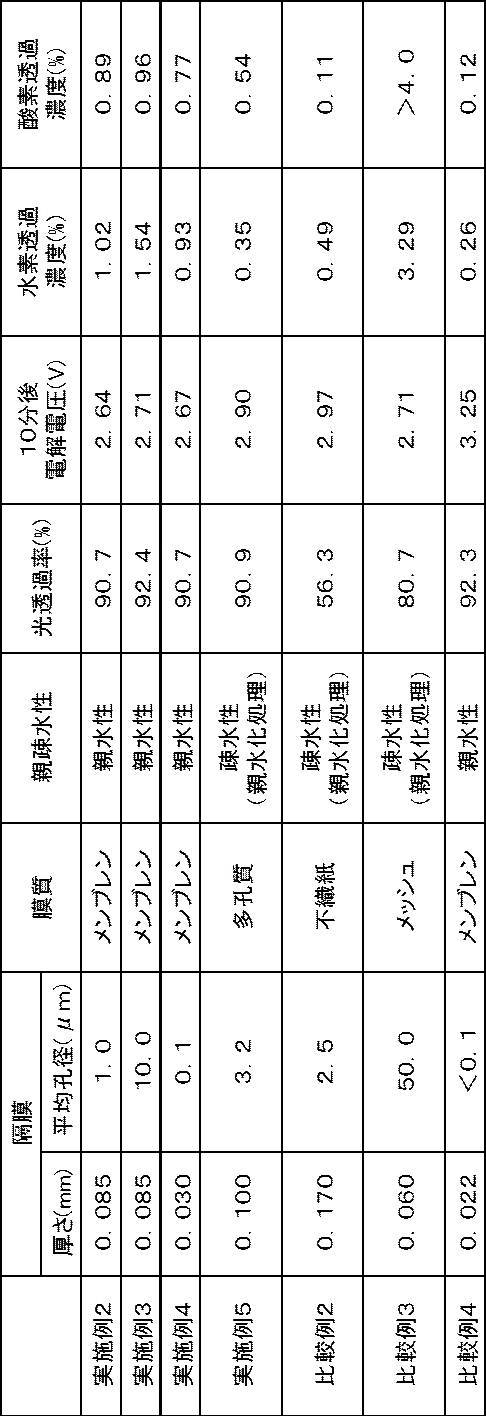
表2に示すように、実施例2~実施例4は、厚さと平均孔径が異なり以外は同じ構成である。実施例2~実施例4から、少なくとも平均孔径が0.1μm~10.0μm、膜厚が35μm~85μm以下において実用的な電解電圧であることを確認した。また、実施例2~実施例4については、隔膜を通過して反対側に通り抜けた酸素の、酸素透過濃度及び水素の水素透過濃度は、後工程で純度をあげるのに実用的な2%以下であることを確認した。
実施例5は、親水化処理を行っているが、光透過率を90%以上にでき、しかも電解電圧を3.0V以下、水素透過率を2%以下にすることができた。
比較例2は、光透過率が低く10分後の電解電圧が高く、変換効率が悪い。
比較例3は、平均孔径が大きく水素透過濃度が3.29%と高く、かつ酸素透過濃度も4.0%超と高く、実用性能としては不適であった。比較例4は、10分後の電解電圧が高く、変換効率が悪い。
実施例5は、親水化処理を行っているが、光透過率を90%以上にでき、しかも電解電圧を3.0V以下、水素透過率を2%以下にすることができた。
比較例2は、光透過率が低く10分後の電解電圧が高く、変換効率が悪い。
比較例3は、平均孔径が大きく水素透過濃度が3.29%と高く、かつ酸素透過濃度も4.0%超と高く、実用性能としては不適であった。比較例4は、10分後の電解電圧が高く、変換効率が悪い。
第3実施例は、電解液を別々に循環させた分離循環方式と、電解液を1つのタンクにまとめて回収して循環させた混合循環方式の効果について調べた。
実施例6が図13に示す構成の人工光合成装置を用いたものであり、実施例7が図14に示す構成の人工光合成装置を用いたものである。
実施例6及び実施例7について、電解電圧を10分後、20分後、60分後、120分後について測定した。その結果を下記表3に示す。
電解電圧の測定方法は、電解水溶液に1M Na2SO4の電解液を用いた点、電解水溶液を図13及び図14に示す方向Dに流し、かつ電解水溶液の流量が4.2cm/秒である点以外、上述の第1実施例と同じであるため、その詳細な説明は省略する。
実施例6が図13に示す構成の人工光合成装置を用いたものであり、実施例7が図14に示す構成の人工光合成装置を用いたものである。
実施例6及び実施例7について、電解電圧を10分後、20分後、60分後、120分後について測定した。その結果を下記表3に示す。
電解電圧の測定方法は、電解水溶液に1M Na2SO4の電解液を用いた点、電解水溶液を図13及び図14に示す方向Dに流し、かつ電解水溶液の流量が4.2cm/秒である点以外、上述の第1実施例と同じであるため、その詳細な説明は省略する。
以下、実施例6及び実施例7について説明する。
(実施例6)
実施例6は、実施例1に比して、酸素発生電極と、水素発生電極とで電解液を別々に循環させた点以外は、実施例1と同じ構成とした。
(実施例7)
実施例7は、実施例1に比して、酸素発生電極と、水素発生電極とで電解液を1つのタンクにまとめて回収して循環させた点以外は、実施例1と同じ構成とした。
(実施例6)
実施例6は、実施例1に比して、酸素発生電極と、水素発生電極とで電解液を別々に循環させた点以外は、実施例1と同じ構成とした。
(実施例7)
実施例7は、実施例1に比して、酸素発生電極と、水素発生電極とで電解液を1つのタンクにまとめて回収して循環させた点以外は、実施例1と同じ構成とした。

表3に示すように、実施例6の分離循環方式と、実施例7の混合循環方式とでは、60分以上経過すると、実施例7の混合循環方式の方が電解電圧が低く維持されている、すなわち、実施例7の方が変換効率が高く維持されている。隔膜を用いた場合、隔膜により酸素発生電極と水素発生電極が仕切られているため、時間が経るにつれて、各区画の電解水溶液のpHの偏りが生じる。これにより電解電圧の上昇、すなわち、変換効率低下が必然的に発生する。しかしながら、実施例7の混合循環方式では、1つのタンクに回収された電解水溶液が循環して利用されるため、タンク内での電解水溶液のpHの偏りが解消され電解電圧の経時上昇を抑制する効果が優れる。
第4実施例は、酸素発生電極と水素発生電極の構成の違いによる効果について調べた。
ベタ電極と呼ばれる平板の電極構成の実施例8と、メッシュ電極構成の実施例9について、10分後の電解電圧を測定した。その結果を下記表4に示す。
電解電圧の測定方法は、電解水溶液に1M Na2SO4の電解液を用いた点、電解水溶液を図15に示す方向Dに流し、かつ電解水溶液の流量が4.2cm/秒である点以外は、上述の第1実施例と同じであるため、その詳細な説明は省略する。
ベタ電極と呼ばれる平板の電極構成の実施例8と、メッシュ電極構成の実施例9について、10分後の電解電圧を測定した。その結果を下記表4に示す。
電解電圧の測定方法は、電解水溶液に1M Na2SO4の電解液を用いた点、電解水溶液を図15に示す方向Dに流し、かつ電解水溶液の流量が4.2cm/秒である点以外は、上述の第1実施例と同じであるため、その詳細な説明は省略する。
以下、実施例8及び実施例9について説明する。
(実施例8)
実施例8は、実施例1と同じ構成である。実施例8は、図13に示す構成の人工光合成装置を用いた。
(実施例9)
実施例9は、実施例1に比して、酸素発生電極及び水素発生電極を、直径0.08mmのプラチナ線が、80本/インチの密度で編まれたメッシュ電極構成とした点以外は、実施例1と同じ構成とした。実施例9は、図15に示す構成の人工光合成装置を用いた。
(実施例8)
実施例8は、実施例1と同じ構成である。実施例8は、図13に示す構成の人工光合成装置を用いた。
(実施例9)
実施例9は、実施例1に比して、酸素発生電極及び水素発生電極を、直径0.08mmのプラチナ線が、80本/インチの密度で編まれたメッシュ電極構成とした点以外は、実施例1と同じ構成とした。実施例9は、図15に示す構成の人工光合成装置を用いた。

表4に示すように、メッシュ電極構成の実施例9は、実施例8と同等の電解電圧を維持でき、高い変換効率を維持できた。
実施例9は、酸素発生電極及び水素発生電極の貫通孔により、発生した気泡が反対側の電極に逃げて、電極の裏を通って流れる。これにより、隔膜と電極間に気泡が挟まれ、電解液の流れ、及び隔膜を通したイオンの流れを妨げ電解電圧が上昇することが抑制される。また、気泡が挟まれることが抑制されることにより、更に電極間隔を狭くすることができるため、電解電圧を下げること、すなわち、変換効率を上げることができる。また、酸素発生電極の貫通孔から太陽光が、水素発生電極に透過するため、酸素発生電極が透明である必要がなく、電気抵抗が高いITO(Indium Tin Oxide)等の透明電極膜を使用が不要になり、更に電解電圧を下げることができる。
実施例9は、酸素発生電極及び水素発生電極の貫通孔により、発生した気泡が反対側の電極に逃げて、電極の裏を通って流れる。これにより、隔膜と電極間に気泡が挟まれ、電解液の流れ、及び隔膜を通したイオンの流れを妨げ電解電圧が上昇することが抑制される。また、気泡が挟まれることが抑制されることにより、更に電極間隔を狭くすることができるため、電解電圧を下げること、すなわち、変換効率を上げることができる。また、酸素発生電極の貫通孔から太陽光が、水素発生電極に透過するため、酸素発生電極が透明である必要がなく、電気抵抗が高いITO(Indium Tin Oxide)等の透明電極膜を使用が不要になり、更に電解電圧を下げることができる。
10、60、70 人工光合成モジュール
12 酸素発生電極
12a、14a 貫通孔
14 水素発生電極
16 隔膜
16a、24a、34a、40a、42a、44a 表面
16b 裏面
17 貫通孔
18 導線
20 容器
22b 底面
22c 第1の壁面
22d 第2の壁面
23a 第1の区画
23b 第2の区画
24 透明部材
26a、26b 供給管
28a、28b 排出管
30 第1の基板
32 第1の導電層
34 第1の光触媒層
36 第1の助触媒
37 助触媒粒子
40 第2の基板
42 第2の導電層
44 第2の光触媒層
46 第2の助触媒
47 助触媒粒子
50、51、52 気泡
62、64 突出部
62a、64a 凸部
62b、64b 凹部
62c、62d、64c、64d 表面
62e、64e 最突端
72a 第1の電極部
72b 第1の隙間
72c、74c 基部
74a 第2の電極部
74b 第2の隙間
80 厚みが0.1mmのナフィオン(登録商標)膜
82 多孔質のセルロース膜
84 孔径が0.1μmの親水性PTFE(ポリエチレンテレフタレート)膜
86 孔径が1.0μmの親水性PTFE(ポリエチレンテレフタレート)膜
88 孔径が10μmの親水性PTFE(ポリエチレンテレフタレート)膜
100、100a、100b、100c 人工光合成装置
102、102a、102b タンク
103 配管
104 ポンプ
105 ガス回収部
106 酸素ガス回収部
107 酸素用管
108 水素ガス回収部
109 水素用管
AQ 水
B 水平面
D 方向
Db 平均気泡径
Dh 孔径
Di 進行方向
Dp 孔径
FA 方向
L 光
Lq 液体
W 方向
d 厚み
h 高さ
φ 角度
12 酸素発生電極
12a、14a 貫通孔
14 水素発生電極
16 隔膜
16a、24a、34a、40a、42a、44a 表面
16b 裏面
17 貫通孔
18 導線
20 容器
22b 底面
22c 第1の壁面
22d 第2の壁面
23a 第1の区画
23b 第2の区画
24 透明部材
26a、26b 供給管
28a、28b 排出管
30 第1の基板
32 第1の導電層
34 第1の光触媒層
36 第1の助触媒
37 助触媒粒子
40 第2の基板
42 第2の導電層
44 第2の光触媒層
46 第2の助触媒
47 助触媒粒子
50、51、52 気泡
62、64 突出部
62a、64a 凸部
62b、64b 凹部
62c、62d、64c、64d 表面
62e、64e 最突端
72a 第1の電極部
72b 第1の隙間
72c、74c 基部
74a 第2の電極部
74b 第2の隙間
80 厚みが0.1mmのナフィオン(登録商標)膜
82 多孔質のセルロース膜
84 孔径が0.1μmの親水性PTFE(ポリエチレンテレフタレート)膜
86 孔径が1.0μmの親水性PTFE(ポリエチレンテレフタレート)膜
88 孔径が10μmの親水性PTFE(ポリエチレンテレフタレート)膜
100、100a、100b、100c 人工光合成装置
102、102a、102b タンク
103 配管
104 ポンプ
105 ガス回収部
106 酸素ガス回収部
107 酸素用管
108 水素ガス回収部
109 水素用管
AQ 水
B 水平面
D 方向
Db 平均気泡径
Dh 孔径
Di 進行方向
Dp 孔径
FA 方向
L 光
Lq 液体
W 方向
d 厚み
h 高さ
φ 角度
Claims (11)
- 光により原料流体を分解して第1の流体を得る、第1の電極と、
前記光により前記原料流体を分解して第2の流体を得る、第2の電極と、
前記第1の電極と前記第2の電極の間に設けられた隔膜とを有する、人工光合成モジュールであって、
前記隔膜は、貫通孔を有する膜で構成され、且つ、温度25℃の純水に1分浸漬させ、前記純水に浸漬された状態において、波長380nm~780nmの波長域の光透過率が60%以上であり、
前記隔膜の前記貫通孔の平均孔径は、0.1μm超50μm未満であることを特徴とする、人工光合成モジュール。 - 前記隔膜は、親水性表面を有する多孔質膜で構成される、請求項1に記載の人工光合成モジュール。
- 前記第1の電極は、第1の基板と、前記第1の基板上に設けられた第1の導電層と、前記第1の導電層上に設けられた第1の光触媒層と、前記第1の光触媒層の少なくとも一部に担持された第1の助触媒とを有し、
前記第2の電極は、第2の基板と、前記第2の基板上に設けられた第2の導電層と、前記第2の導電層上に設けられた第2の光触媒層と、前記第2の光触媒層の少なくとも一部に担持された第2の助触媒とを有し、前記第1の電極と前記隔膜と前記第2の電極が、前記光の進行方向に沿って直列に配置されている、請求項1又は2に記載の人工光合成モジュール。 - 前記光が前記第1の電極側から入射され、且つ、前記第1の電極が有する前記第1の基板が透明である、請求項3に記載の人工光合成モジュール。
- 前記第1の電極と前記第2の電極とは、複数の貫通孔を有し、
前記隔膜は、前記第1の電極と前記第2の電極と間に配置されて挟まれている請求項1~4のいずれか1項に記載の人工光合成モジュール。 - 前記第1の流体は気体又は液体であり、前記第2の流体は気体又は液体である、請求項1~5のいずれか1項に記載の人工光合成モジュール。
- 前記原料流体が水であり、前記第1の流体が酸素であり、前記第2の流体が水素である、請求項1~6のいずれか1項に記載の人工光合成モジュール。
- 原料流体を分解して流体を得る人工光合成モジュール、
前記原料流体を貯蔵するタンク、
前記タンクと前記人工光合成モジュールに接続され、前記人工光合成モジュールに前記原料流体を供給する供給管、
前記タンクと前記人工光合成モジュールに接続され、前記人工光合成モジュールから前記原料流体を回収する排出管、
前記原料流体を前記供給管と前記排出管を介して前記タンクと前記人工光合成モジュールとの間で循環させるポンプ、及び
前記人工光合成モジュールで得られた流体を回収するガス回収部、を有する、人工光合成装置であって、
光により前記原料流体を分解して第1の流体を得る、第1の基板と、前記第1の基板上に設けられた第1の導電層と、前記第1の導電層上に設けられた第1の光触媒層と、前記第1の光触媒層の少なくとも一部に担持された第1の助触媒とを有する第1の電極と、
前記光により前記原料流体を分解して第2の流体を得る、第2の基板と、前記第2の基板上に設けられた第2の導電層と、前記第2の導電層上に設けられた第2の光触媒層と、前記第2の光触媒層の少なくとも一部に担持された第2の助触媒とを有する第2の電極と、
前記第1の電極と前記第2の電極の間に設けられた隔膜とを具備し、前記第1の電極と前記第2の電極は、互いに導線を介して電気的に接続されており、
前記隔膜は、貫通孔を有する膜で構成され、且つ、温度25℃の純水に1分浸漬させ、前記純水に浸漬された状態において、波長380nm~780nmの波長域の光透過率が60%以上であり、前記隔膜前記貫通孔の平均孔径は、0.1μm超50μm未満である前記人工光合成モジュールが複数配置されていることを特徴とする、人工光合成装置。 - 前記人工光合成モジュールは前記隔膜で区画された、前記第1の電極が設けられた第1の区画と、前記第2の電極が設けられた第2の区画とを有し、
前記供給管は、前記第1の区画及び前記第2の区画に前記原料流体を供給し、
前記排出管は、前記第1の区画及び前記第2の区画の前記原料流体を回収し、
前記原料流体を貯蔵するタンクは、前記人工光合成モジュールの前記第1の区画の前記原料流体、及び前記第2の区画の前記原料流体が、混合されて貯蔵され、
前記タンクに混合されて貯蔵された前記原料流体が、前記ポンプにより前記供給管を介して前記第1の区画及び前記第2の区画に前記原料流体を供給される、請求項8に記載の人工光合成装置。 - 前記第1の流体は気体又は液体であり、前記第2の流体は気体又は液体である、請求項8又は9に記載の人工光合成装置。
- 前記原料流体が水であり、前記第1の流体が酸素であり、前記第2の流体が水素である、請求項8~10のいずれか1項に記載の人工光合成装置。
Priority Applications (3)
| Application Number | Priority Date | Filing Date | Title |
|---|---|---|---|
| CN201780038929.5A CN109415824B (zh) | 2016-06-23 | 2017-06-19 | 人工光合作用模块及人工光合作用装置 |
| JP2018524068A JP6535818B2 (ja) | 2016-06-23 | 2017-06-19 | 人工光合成モジュール及び人工光合成装置 |
| US16/228,398 US20190131470A1 (en) | 2016-06-23 | 2018-12-20 | Artificial photosynthesis module and artificial photosynthesis device |
Applications Claiming Priority (2)
| Application Number | Priority Date | Filing Date | Title |
|---|---|---|---|
| JP2016124514 | 2016-06-23 | ||
| JP2016-124514 | 2016-06-23 |
Related Child Applications (1)
| Application Number | Title | Priority Date | Filing Date |
|---|---|---|---|
| US16/228,398 Continuation US20190131470A1 (en) | 2016-06-23 | 2018-12-20 | Artificial photosynthesis module and artificial photosynthesis device |
Publications (1)
| Publication Number | Publication Date |
|---|---|
| WO2017221866A1 true WO2017221866A1 (ja) | 2017-12-28 |
Family
ID=60783442
Family Applications (1)
| Application Number | Title | Priority Date | Filing Date |
|---|---|---|---|
| PCT/JP2017/022461 Ceased WO2017221866A1 (ja) | 2016-06-23 | 2017-06-19 | 人工光合成モジュール及び人工光合成装置 |
Country Status (4)
| Country | Link |
|---|---|
| US (1) | US20190131470A1 (ja) |
| JP (1) | JP6535818B2 (ja) |
| CN (1) | CN109415824B (ja) |
| WO (1) | WO2017221866A1 (ja) |
Cited By (9)
| Publication number | Priority date | Publication date | Assignee | Title |
|---|---|---|---|---|
| JP2020012135A (ja) * | 2018-07-13 | 2020-01-23 | 富士フイルム株式会社 | 人工光合成モジュール |
| JP2020122169A (ja) * | 2019-01-29 | 2020-08-13 | 富士通株式会社 | 酸素発生電極、及び酸素発生装置 |
| JP2020139172A (ja) * | 2019-02-26 | 2020-09-03 | 国立研究開発法人産業技術総合研究所 | 過酸化水素の製造方法及び過酸化水素の製造装置 |
| JP2020176301A (ja) * | 2019-04-18 | 2020-10-29 | 三井化学株式会社 | 水素発生用電極及び水素発生用電極の製造方法 |
| JP2023081781A (ja) * | 2021-12-01 | 2023-06-13 | 国立大学法人 東京大学 | 電極、水電解槽、水電解装置、二酸化炭素還元電解槽及び二酸化炭素電解装置 |
| WO2023182282A1 (ja) * | 2022-03-22 | 2023-09-28 | 千代田化工建設株式会社 | 光触媒を用いた水分解装置及びこれを備えた水分解システム |
| WO2024195073A1 (ja) * | 2023-03-23 | 2024-09-26 | 三菱電機株式会社 | 光化学反応器 |
| WO2025079345A1 (ja) * | 2023-10-12 | 2025-04-17 | パナソニックホールディングス株式会社 | 水分解装置に用いるための水分解セル、及び、水分解装置 |
| WO2025173297A1 (ja) * | 2024-02-15 | 2025-08-21 | パナソニックホールディングス株式会社 | 水分解装置 |
Families Citing this family (5)
| Publication number | Priority date | Publication date | Assignee | Title |
|---|---|---|---|---|
| TR201907838A2 (tr) * | 2019-05-23 | 2020-12-21 | Arcelik As | Oksi̇jen üreten bi̇r ci̇haz ve çalişma yöntemi̇ |
| CN217869114U (zh) * | 2020-08-19 | 2022-11-22 | 爱可依科技(上海)有限公司 | 一种电极片单元及臭氧发生器 |
| KR102568691B1 (ko) * | 2021-01-27 | 2023-08-21 | 인천대학교 산학협력단 | 광전기화학반응에 의하여 수소를 생성하는 광음극구조층 및 이의 제조방법 |
| CN114956004B (zh) * | 2022-05-17 | 2023-12-05 | 宝武清洁能源鄂州有限公司 | 一种利用光合作用生产出氧气的制氧机 |
| FR3141947A1 (fr) * | 2022-11-10 | 2024-05-17 | Engie | Cellule d’électrolyse photo-assistée à boîtier conducteur et électrolyseur la comportant |
Citations (4)
| Publication number | Priority date | Publication date | Assignee | Title |
|---|---|---|---|---|
| JPH01134429A (ja) * | 1987-11-20 | 1989-05-26 | Brother Ind Ltd | エレクトロクロミック表示装置 |
| JPH07150379A (ja) * | 1993-11-29 | 1995-06-13 | Japan Energy Corp | 水分解装置および水分解方法 |
| JP2005044758A (ja) * | 2003-07-25 | 2005-02-17 | National Institute Of Advanced Industrial & Technology | 可視光応答性の膜状多孔質半導体光電極 |
| JP2006089336A (ja) * | 2004-09-24 | 2006-04-06 | National Institute Of Advanced Industrial & Technology | 水の光分解反応により水素および酸素を製造する装置 |
Family Cites Families (11)
| Publication number | Priority date | Publication date | Assignee | Title |
|---|---|---|---|---|
| US4466869A (en) * | 1983-08-15 | 1984-08-21 | Energy Conversion Devices, Inc. | Photolytic production of hydrogen |
| US6471834B2 (en) * | 2000-01-31 | 2002-10-29 | A. Nicholas Roe | Photo-assisted electrolysis apparatus |
| GB0204028D0 (en) * | 2002-02-20 | 2002-04-03 | Stamford Memory Polymers Ltd | Method of photoelectrolysis |
| WO2006110613A2 (en) * | 2005-04-11 | 2006-10-19 | The University Of Toledo | Integrated photovoltaic-electrolysis cell |
| US8388818B1 (en) * | 2007-07-16 | 2013-03-05 | Shalini Menezes | Photoelectrochemical generation of hydrogen |
| EP2439313B1 (en) * | 2009-06-02 | 2016-09-21 | Panasonic Intellectual Property Management Co., Ltd. | Photoelectrochemical cell |
| IN2012DN02262A (ja) * | 2009-09-09 | 2015-08-21 | Mitsui Chemicals Inc | |
| JP5719555B2 (ja) * | 2010-09-28 | 2015-05-20 | シャープ株式会社 | 水素製造装置および水素製造方法 |
| BR112014030589A2 (pt) * | 2012-06-08 | 2017-06-27 | Tennant Co | sistema de limpeza, e, método para limpar uma superfície |
| US9774052B2 (en) * | 2013-02-21 | 2017-09-26 | Panasonic Intellectual Property Management Co., Ltd. | Hydrogen producing device and hydrogen producing unit and energy system including the hydrogen producing device and the hydrogen producing unit |
| WO2016148302A1 (ja) * | 2015-03-18 | 2016-09-22 | 旭化成株式会社 | アルカリ水電解用隔膜、アルカリ水電解装置、水素の製造方法及びアルカリ水電解用隔膜の製造方法 |
-
2017
- 2017-06-19 WO PCT/JP2017/022461 patent/WO2017221866A1/ja not_active Ceased
- 2017-06-19 CN CN201780038929.5A patent/CN109415824B/zh not_active Expired - Fee Related
- 2017-06-19 JP JP2018524068A patent/JP6535818B2/ja not_active Expired - Fee Related
-
2018
- 2018-12-20 US US16/228,398 patent/US20190131470A1/en not_active Abandoned
Patent Citations (4)
| Publication number | Priority date | Publication date | Assignee | Title |
|---|---|---|---|---|
| JPH01134429A (ja) * | 1987-11-20 | 1989-05-26 | Brother Ind Ltd | エレクトロクロミック表示装置 |
| JPH07150379A (ja) * | 1993-11-29 | 1995-06-13 | Japan Energy Corp | 水分解装置および水分解方法 |
| JP2005044758A (ja) * | 2003-07-25 | 2005-02-17 | National Institute Of Advanced Industrial & Technology | 可視光応答性の膜状多孔質半導体光電極 |
| JP2006089336A (ja) * | 2004-09-24 | 2006-04-06 | National Institute Of Advanced Industrial & Technology | 水の光分解反応により水素および酸素を製造する装置 |
Cited By (17)
| Publication number | Priority date | Publication date | Assignee | Title |
|---|---|---|---|---|
| JP2020012135A (ja) * | 2018-07-13 | 2020-01-23 | 富士フイルム株式会社 | 人工光合成モジュール |
| JP2020122169A (ja) * | 2019-01-29 | 2020-08-13 | 富士通株式会社 | 酸素発生電極、及び酸素発生装置 |
| JP7205255B2 (ja) | 2019-01-29 | 2023-01-17 | 富士通株式会社 | 酸素発生電極、及び酸素発生装置 |
| JP2020139172A (ja) * | 2019-02-26 | 2020-09-03 | 国立研究開発法人産業技術総合研究所 | 過酸化水素の製造方法及び過酸化水素の製造装置 |
| JP7215727B2 (ja) | 2019-02-26 | 2023-01-31 | 国立研究開発法人産業技術総合研究所 | 過酸化水素の製造方法及び過酸化水素の製造装置 |
| JP2020176301A (ja) * | 2019-04-18 | 2020-10-29 | 三井化学株式会社 | 水素発生用電極及び水素発生用電極の製造方法 |
| JP7320775B2 (ja) | 2019-04-18 | 2023-08-04 | 三井化学株式会社 | 水素発生用電極及び水素発生用電極の製造方法 |
| JP7831757B2 (ja) | 2021-12-01 | 2026-03-17 | 国立大学法人 東京大学 | 電極、水電解槽、水電解装置、二酸化炭素還元電解槽及び二酸化炭素電解装置 |
| JP2023081781A (ja) * | 2021-12-01 | 2023-06-13 | 国立大学法人 東京大学 | 電極、水電解槽、水電解装置、二酸化炭素還元電解槽及び二酸化炭素電解装置 |
| WO2023182282A1 (ja) * | 2022-03-22 | 2023-09-28 | 千代田化工建設株式会社 | 光触媒を用いた水分解装置及びこれを備えた水分解システム |
| JP7809277B2 (ja) | 2022-03-22 | 2026-02-02 | 千代田化工建設株式会社 | 光触媒を用いた水分解装置及びこれを備えた水分解システム |
| JP2023139749A (ja) * | 2022-03-22 | 2023-10-04 | 千代田化工建設株式会社 | 光触媒を用いた水分解装置及びこれを備えた水分解システム |
| WO2024195073A1 (ja) * | 2023-03-23 | 2024-09-26 | 三菱電機株式会社 | 光化学反応器 |
| JPWO2024195073A1 (ja) * | 2023-03-23 | 2024-09-26 | ||
| JP7811949B2 (ja) | 2023-03-23 | 2026-02-06 | 三菱電機株式会社 | 光化学反応器 |
| WO2025079345A1 (ja) * | 2023-10-12 | 2025-04-17 | パナソニックホールディングス株式会社 | 水分解装置に用いるための水分解セル、及び、水分解装置 |
| WO2025173297A1 (ja) * | 2024-02-15 | 2025-08-21 | パナソニックホールディングス株式会社 | 水分解装置 |
Also Published As
| Publication number | Publication date |
|---|---|
| JPWO2017221866A1 (ja) | 2019-05-16 |
| JP6535818B2 (ja) | 2019-06-26 |
| US20190131470A1 (en) | 2019-05-02 |
| CN109415824B (zh) | 2019-12-27 |
| CN109415824A (zh) | 2019-03-01 |
Similar Documents
| Publication | Publication Date | Title |
|---|---|---|
| JP6535818B2 (ja) | 人工光合成モジュール及び人工光合成装置 | |
| US11098410B2 (en) | Artificial photosynthesis module | |
| CN104797741B (zh) | 光化学反应装置 | |
| US10406516B2 (en) | Electrode for water-splitting reaction and method for producing the same | |
| US10351964B2 (en) | Artificial photosynthesis module | |
| US10258971B2 (en) | Photocatalyst electrode and artificial photosynthesis module | |
| US9593053B1 (en) | Photoelectrosynthetically active heterostructures | |
| JP5641501B2 (ja) | 水素製造装置 | |
| Benton et al. | Utilisation of GaN and InGaN/GaN with nanoporous structures for water splitting | |
| JP6184312B2 (ja) | 人工光合成アレイ | |
| JP6371854B2 (ja) | 人工光合成モジュール | |
| US10384195B2 (en) | Artificial photosynthesis module | |
| WO2009002424A2 (en) | Nano engineered photo electrode for photoelectrochemical, photovoltaic and sensor applications | |
| JP6559710B2 (ja) | 水素発生電極 | |
| JP2020012134A (ja) | 人工光合成モジュール | |
| WO2018198861A1 (ja) | 人工光合成モジュール用電極及び人工光合成モジュール | |
| KR102156188B1 (ko) | 실리콘 나노 피라미드 전극을 구비한 광전기화학 시스템 | |
| JP2020012135A (ja) | 人工光合成モジュール |
Legal Events
| Date | Code | Title | Description |
|---|---|---|---|
| 121 | Ep: the epo has been informed by wipo that ep was designated in this application |
Ref document number: 17815334 Country of ref document: EP Kind code of ref document: A1 |
|
| ENP | Entry into the national phase |
Ref document number: 2018524068 Country of ref document: JP Kind code of ref document: A |
|
| NENP | Non-entry into the national phase |
Ref country code: DE |
|
| 122 | Ep: pct application non-entry in european phase |
Ref document number: 17815334 Country of ref document: EP Kind code of ref document: A1 |