WO2017221791A1 - レンズ駆動装置、カメラモジュール及びカメラ搭載装置 - Google Patents
レンズ駆動装置、カメラモジュール及びカメラ搭載装置 Download PDFInfo
- Publication number
- WO2017221791A1 WO2017221791A1 PCT/JP2017/022000 JP2017022000W WO2017221791A1 WO 2017221791 A1 WO2017221791 A1 WO 2017221791A1 JP 2017022000 W JP2017022000 W JP 2017022000W WO 2017221791 A1 WO2017221791 A1 WO 2017221791A1
- Authority
- WO
- WIPO (PCT)
- Prior art keywords
- magnet
- coil
- driving device
- lens driving
- unit
- Prior art date
Links
Images


Classifications
-
- G—PHYSICS
- G02—OPTICS
- G02B—OPTICAL ELEMENTS, SYSTEMS OR APPARATUS
- G02B7/00—Mountings, adjusting means, or light-tight connections, for optical elements
- G02B7/02—Mountings, adjusting means, or light-tight connections, for optical elements for lenses
- G02B7/04—Mountings, adjusting means, or light-tight connections, for optical elements for lenses with mechanism for focusing or varying magnification
- G02B7/09—Mountings, adjusting means, or light-tight connections, for optical elements for lenses with mechanism for focusing or varying magnification adapted for automatic focusing or varying magnification
-
- G—PHYSICS
- G02—OPTICS
- G02B—OPTICAL ELEMENTS, SYSTEMS OR APPARATUS
- G02B13/00—Optical objectives specially designed for the purposes specified below
- G02B13/001—Miniaturised objectives for electronic devices, e.g. portable telephones, webcams, PDAs, small digital cameras
-
- G—PHYSICS
- G02—OPTICS
- G02B—OPTICAL ELEMENTS, SYSTEMS OR APPARATUS
- G02B27/00—Optical systems or apparatus not provided for by any of the groups G02B1/00 - G02B26/00, G02B30/00
- G02B27/64—Imaging systems using optical elements for stabilisation of the lateral and angular position of the image
- G02B27/646—Imaging systems using optical elements for stabilisation of the lateral and angular position of the image compensating for small deviations, e.g. due to vibration or shake
-
- G—PHYSICS
- G02—OPTICS
- G02B—OPTICAL ELEMENTS, SYSTEMS OR APPARATUS
- G02B7/00—Mountings, adjusting means, or light-tight connections, for optical elements
- G02B7/02—Mountings, adjusting means, or light-tight connections, for optical elements for lenses
-
- G—PHYSICS
- G02—OPTICS
- G02B—OPTICAL ELEMENTS, SYSTEMS OR APPARATUS
- G02B7/00—Mountings, adjusting means, or light-tight connections, for optical elements
- G02B7/02—Mountings, adjusting means, or light-tight connections, for optical elements for lenses
- G02B7/023—Mountings, adjusting means, or light-tight connections, for optical elements for lenses permitting adjustment
-
- G—PHYSICS
- G02—OPTICS
- G02B—OPTICAL ELEMENTS, SYSTEMS OR APPARATUS
- G02B7/00—Mountings, adjusting means, or light-tight connections, for optical elements
- G02B7/02—Mountings, adjusting means, or light-tight connections, for optical elements for lenses
- G02B7/04—Mountings, adjusting means, or light-tight connections, for optical elements for lenses with mechanism for focusing or varying magnification
-
- G—PHYSICS
- G03—PHOTOGRAPHY; CINEMATOGRAPHY; ANALOGOUS TECHNIQUES USING WAVES OTHER THAN OPTICAL WAVES; ELECTROGRAPHY; HOLOGRAPHY
- G03B—APPARATUS OR ARRANGEMENTS FOR TAKING PHOTOGRAPHS OR FOR PROJECTING OR VIEWING THEM; APPARATUS OR ARRANGEMENTS EMPLOYING ANALOGOUS TECHNIQUES USING WAVES OTHER THAN OPTICAL WAVES; ACCESSORIES THEREFOR
- G03B13/00—Viewfinders; Focusing aids for cameras; Means for focusing for cameras; Autofocus systems for cameras
- G03B13/32—Means for focusing
- G03B13/34—Power focusing
- G03B13/36—Autofocus systems
-
- G—PHYSICS
- G03—PHOTOGRAPHY; CINEMATOGRAPHY; ANALOGOUS TECHNIQUES USING WAVES OTHER THAN OPTICAL WAVES; ELECTROGRAPHY; HOLOGRAPHY
- G03B—APPARATUS OR ARRANGEMENTS FOR TAKING PHOTOGRAPHS OR FOR PROJECTING OR VIEWING THEM; APPARATUS OR ARRANGEMENTS EMPLOYING ANALOGOUS TECHNIQUES USING WAVES OTHER THAN OPTICAL WAVES; ACCESSORIES THEREFOR
- G03B3/00—Focusing arrangements of general interest for cameras, projectors or printers
- G03B3/10—Power-operated focusing
-
- G—PHYSICS
- G03—PHOTOGRAPHY; CINEMATOGRAPHY; ANALOGOUS TECHNIQUES USING WAVES OTHER THAN OPTICAL WAVES; ELECTROGRAPHY; HOLOGRAPHY
- G03B—APPARATUS OR ARRANGEMENTS FOR TAKING PHOTOGRAPHS OR FOR PROJECTING OR VIEWING THEM; APPARATUS OR ARRANGEMENTS EMPLOYING ANALOGOUS TECHNIQUES USING WAVES OTHER THAN OPTICAL WAVES; ACCESSORIES THEREFOR
- G03B30/00—Camera modules comprising integrated lens units and imaging units, specially adapted for being embedded in other devices, e.g. mobile phones or vehicles
-
- G—PHYSICS
- G03—PHOTOGRAPHY; CINEMATOGRAPHY; ANALOGOUS TECHNIQUES USING WAVES OTHER THAN OPTICAL WAVES; ELECTROGRAPHY; HOLOGRAPHY
- G03B—APPARATUS OR ARRANGEMENTS FOR TAKING PHOTOGRAPHS OR FOR PROJECTING OR VIEWING THEM; APPARATUS OR ARRANGEMENTS EMPLOYING ANALOGOUS TECHNIQUES USING WAVES OTHER THAN OPTICAL WAVES; ACCESSORIES THEREFOR
- G03B5/00—Adjustment of optical system relative to image or object surface other than for focusing
- G03B5/02—Lateral adjustment of lens
-
- H—ELECTRICITY
- H04—ELECTRIC COMMUNICATION TECHNIQUE
- H04N—PICTORIAL COMMUNICATION, e.g. TELEVISION
- H04N23/00—Cameras or camera modules comprising electronic image sensors; Control thereof
- H04N23/50—Constructional details
- H04N23/55—Optical parts specially adapted for electronic image sensors; Mounting thereof
-
- G—PHYSICS
- G03—PHOTOGRAPHY; CINEMATOGRAPHY; ANALOGOUS TECHNIQUES USING WAVES OTHER THAN OPTICAL WAVES; ELECTROGRAPHY; HOLOGRAPHY
- G03B—APPARATUS OR ARRANGEMENTS FOR TAKING PHOTOGRAPHS OR FOR PROJECTING OR VIEWING THEM; APPARATUS OR ARRANGEMENTS EMPLOYING ANALOGOUS TECHNIQUES USING WAVES OTHER THAN OPTICAL WAVES; ACCESSORIES THEREFOR
- G03B2205/00—Adjustment of optical system relative to image or object surface other than for focusing
- G03B2205/0007—Movement of one or more optical elements for control of motion blur
- G03B2205/0015—Movement of one or more optical elements for control of motion blur by displacing one or more optical elements normal to the optical axis
-
- G—PHYSICS
- G03—PHOTOGRAPHY; CINEMATOGRAPHY; ANALOGOUS TECHNIQUES USING WAVES OTHER THAN OPTICAL WAVES; ELECTROGRAPHY; HOLOGRAPHY
- G03B—APPARATUS OR ARRANGEMENTS FOR TAKING PHOTOGRAPHS OR FOR PROJECTING OR VIEWING THEM; APPARATUS OR ARRANGEMENTS EMPLOYING ANALOGOUS TECHNIQUES USING WAVES OTHER THAN OPTICAL WAVES; ACCESSORIES THEREFOR
- G03B2205/00—Adjustment of optical system relative to image or object surface other than for focusing
- G03B2205/0053—Driving means for the movement of one or more optical element
- G03B2205/0069—Driving means for the movement of one or more optical element using electromagnetic actuators, e.g. voice coils
Definitions
- the present invention relates to a lens driving device, a camera module, and a camera mounting device.
- a small camera module is mounted on a mobile terminal such as a smartphone.
- a camera module has an auto-focus (Auto-Focus: hereinafter abbreviated as “AF”) function that automatically performs focusing when shooting a subject, and shake correction that optically corrects vibrations that occur during shooting.
- AF Auto-Focus
- OIS Optical Image Stabilization
- Patent Document 1 and Patent Document 2 describe that an AF function and an OIS function are realized by a voice coil motor including a magnet and a coil.
- a camera module having a plurality of lens driving devices such as a dual camera
- the dual camera has various possibilities depending on the usage scene, such as being able to simultaneously capture two images with different focal lengths, or simultaneously capture still images and moving images.
- the present invention has been made in view of the above problems, and provides a lens driving device, a camera module, and a camera mounting device suitable for a dual camera application that can suppress magnetic interference with other adjacent lens driving devices. For the purpose.
- the main present invention that solves the above-described problems includes a first coil portion that is disposed around a lens holder that holds a lens portion, and a magnet that is disposed radially away from the first coil portion. And a first support member that supports an autofocus movable part including the first coil part so as to be movable in an optical axis direction with respect to an autofocus fixed part including the magnet part, An autofocus drive unit that automatically focuses using a drive force of a voice coil motor composed of one coil unit and the magnet unit, and the magnet unit disposed in the autofocus drive unit And a second coil part that is spaced apart from the magnet part in the optical axis direction, and the magnet part with respect to a shake correction fixing part that includes the second coil part.
- a second support member that supports the shake correction movable portion so as to be swingable in a plane orthogonal to the optical axis, and the driving force of the voice coil motor configured by the second coil portion and the magnet portion is increased.
- a shake correction driving unit that performs shake correction using the first and second magnets arranged on two opposite sides of the substantially rectangular four sides in plan view.
- the second magnet disposed on the other side, and the side facing the second magnet is a lens driving device that is a magnet non-arranged portion where no magnet is disposed.
- the lens driving device according to the present invention can suppress magnetic interference with other adjacent lens driving devices.
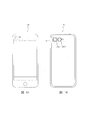
- FIG. 1A and 1B are diagrams showing a smartphone equipped with a camera module according to the first embodiment.
- FIG. 2 is an external perspective view of the camera module according to the first embodiment.
- FIG. 3 is an exploded perspective view of the camera module according to the first embodiment.
- FIG. 4 is an exploded perspective view of the camera module according to the first embodiment.
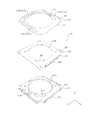
- FIG. 5 is an exploded perspective view of the lens driving device according to the first embodiment.
- FIG. 6 is an exploded perspective view of the lens driving device according to the first embodiment.
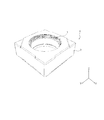
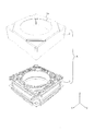
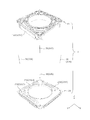
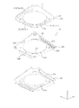
- FIG. 7 is an exploded perspective view of the OIS movable portion of the lens driving device according to the first embodiment.
- FIG. 8 is an exploded perspective view of the OIS movable portion of the lens driving device according to the first embodiment.
- FIG. 1A and 1B are diagrams showing a smartphone equipped with a camera module according to the first embodiment.
- FIG. 2 is an external perspective view of the camera module according to the first embodiment.
- FIG. 3 is an exploded perspective view of the camera
- FIG. 9 is an enlarged view showing the configuration of the AF control unit of the lens driving device according to the first embodiment.
- 10A and 10B are plan views of the upper elastic support member of the lens driving device according to the first embodiment.
- FIG. 11 is an exploded perspective view of the OIS fixing portion of the lens driving device according to the first embodiment.
- FIG. 12 is an exploded perspective view of the OIS fixing portion of the lens driving device according to the first embodiment.
- FIG. 13A and FIG. 13B are diagrams for explaining the arrangement positions of the magnets of the lens driving device according to the first embodiment.
- 14A and 14B are diagrams illustrating an example of a configuration of a lens driving device according to the second embodiment.
- FIG. 15A and FIG. 15B are diagrams showing an example of the configuration of the lens driving device according to the third embodiment.
- FIG. 16A and FIG. 16B are diagrams showing an example of the configuration of the lens driving device according to the fourth embodiment.
- FIG. 17A and FIG. 17B are diagrams showing an example of the configuration of a lens driving device according to the fifth embodiment.
- 18A and 18B are diagrams illustrating an example of a configuration of a lens driving device according to the sixth embodiment.
- 19A and 19B are diagrams illustrating an example of the configuration of a lens driving device according to the seventh embodiment.
- 20A, 20B, and 20C are diagrams illustrating an example of the configuration of the lens driving device according to the eighth embodiment.
- FIG. 21A and FIG. 21B are diagrams showing an example of the configuration of the lens driving device according to the ninth embodiment.
- FIGS. 1A and 1B are diagrams showing a smartphone M equipped with a camera module A according to the present embodiment.
- 1A is a front view of the smartphone M
- FIG. 1B is a rear view of the smartphone M.
- the smartphone M has a dual camera composed of two adjacent rear cameras OC1 and OC2.
- the camera module A according to the present embodiment is applied to at least one rear camera OC1.
- the camera module A has the AF function and the OIS function described above.
- the other rear camera OC2 may have the same configuration as the camera module A according to the present embodiment, or may have another configuration having a voice coil motor. .
- FIG. 2 is an external perspective view of the camera module A.
- FIG. 3 and 4 are exploded perspective views of the camera module A.
- FIG. 3 is an upper perspective view
- FIG. 4 is a lower perspective view.
- the camera module A is mounted so that the X direction is the up / down direction (or left / right direction), the Y direction is the left / right direction (or up / down direction), and the Z direction is the front / rear direction when shooting is actually performed with the smartphone M.
- the X direction and the Y direction orthogonal to the Z axis are referred to as “optical axis orthogonal directions”.
- the camera module A includes a lens driving device 1 that realizes an AF function and an OIS function, a lens unit (not shown) in which a lens is housed in a cylindrical lens barrel, and an image that captures a subject image formed by the lens unit.
- a cover (not shown) and a cover 2 covering the whole.
- the cover 2 is a square-shaped covered quadrangular cylinder in plan view as viewed from the optical axis direction, and has a circular opening 2a on the upper surface. A lens portion (not shown) faces the outside through the opening 2a.
- the cover 2 is fixed to the base 21 (see FIGS. 11 and 12) of the OIS fixing unit 20 of the lens driving device 1.
- the imaging unit has an imaging element (not shown) and is arranged on the optical axis direction imaging side of the lens driving device 1.
- the imaging element (not shown) is configured by, for example, a charge-coupled device (CCD) type image sensor, a complementary metal-oxide semiconductor (CMOS) type image sensor, or the like.
- An image sensor (not shown) captures a subject image formed by a lens unit (not shown).
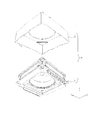
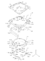
- FIGS. 5 and 6 are exploded perspective views of the lens driving device 1.
- FIG. 5 is an upper perspective view
- FIG. 6 is a lower perspective view.
- the lens driving device 1 includes an OIS movable portion 10, an OIS fixed portion 20, an OIS support member 30, and the like.
- the OIS movable part 10 has an OIS magnet part that constitutes a voice coil motor for OIS, and is a part that swings in the XY plane during shake correction.
- the OIS fixing portion 20 has a coil portion 231 for OIS that constitutes a voice coil motor for OIS, and is a portion that supports the OIS movable portion 10 via the OIS support member 30.
- the moving magnet method is adopted for the OIS drive unit of the lens drive device 1.
- the OIS movable unit 10 includes an AF drive unit (an AF movable unit 11 and an AF fixing unit 12, see FIGS. 7 and 8).
- the OIS movable unit 10 is disposed apart from the OIS fixing unit 20 on the light receiving side in the optical axis direction, and is connected to the OIS fixing unit 20 by the OIS support member 30.
- the OIS support member 30 includes four suspension wires extending along the Z direction (hereinafter referred to as “suspension wire 30”).
- One end (upper end) of the suspension wire 30 is fixed to the OIS movable portion 10 (upper elastic support member 13, see FIGS. 7 and 8), and the other end (lower end) is the OIS fixing portion 20 (coil substrate 23, FIG. 11, FIG. 12).
- the OIS movable unit 10 is supported by the suspension wire 30 so as to be swingable in the XY plane.
- the suspension wires 31A and 31B are used as signal paths for transmitting control signals to the control IC 161 (see FIG. 9), and the suspension wires 32A and 32B are supplied with power from the control IC 161. Used as a path (hereinafter referred to as “signal suspension wires 31A and 31B” and “power supply suspension wires 32A and 32B”).
- FIG. 7 and 8 are exploded perspective views of the OIS movable unit 10. 7 is an upper perspective view, and FIG. 8 is a lower perspective view.
- the OIS movable unit 10 includes an AF movable unit 11, an AF fixed unit 12, AF support members 13 and 14, AF power supply lines 171 and 172, signal lines 173 and 174, and the like. Prepare.
- the AF movable portion 11 has an AF coil portion 112 that constitutes an AF voice coil motor, and is a portion that moves in the optical axis direction during focusing.
- the AF fixing portion 12 has a magnet portion 122 (AF magnet portion) and is a portion that supports the AF movable portion 11 via the AF support members 13 and 14. In other words, the moving coil method is employed for the AF driving unit of the lens driving device 1.
- the AF movable part 11 is arranged to be spaced radially inward with respect to the AF fixing part 12 and connected to the AF fixing part 12 by AF support members 13 and 14.
- the AF support member 13 is an upper elastic support member that supports the AF movable portion 11 on the upper side with respect to the AF fixed portion 12 (hereinafter referred to as “upper elastic support member 13”)
- the AF support member 14 is an AF This is a lower elastic support member that supports the AF movable portion 11 on the lower side with respect to the fixed portion 12 (hereinafter referred to as “lower elastic support member 14”).
- the AF movable unit 11 includes a lens holder 111, an AF coil unit 112, and position detection magnets 15A and 15B.
- the lens holder 111 includes a cylindrical lens housing portion 111a and a portion sandwiched between flange portions 111b and 111c having flange portions 111b and 111c having substantially octagonal shapes in a plan view protruding outward in the radial direction from the lens housing portion 111a (hereinafter, referred to as the lens holder 111a).
- the AF coil portion 112 is wound around the “coil winding portion”.
- the upper surface of the flange portion 111b serves as a locked portion for restricting the movement of the AF movable portion 11 toward the light receiving direction in the optical axis direction.
- the lens holder 111 has four portions intersecting with a direction (hereinafter referred to as “diagonal direction”) rotated by 45 ° in the X direction and Y direction (hereinafter referred to as “cross direction”) on the outer periphery of the upper portion of the lens housing portion 111a.
- a direction hereinafter referred to as “diagonal direction”
- Y direction hereinafter referred to as “cross direction”
- an upper spring fixing portion 111d for fixing the upper elastic support member 13 is provided.
- the lens holder 111 has a first stopper portion 111h along the outer periphery of the lens housing portion 111a.
- the lower surface of the first stopper portion 111h serves as a locked portion for restricting the movement of the AF movable portion 11 toward the image forming direction in the optical axis direction.
- the lens holder 111 has a binding portion 111e that protrudes radially outward from two upper spring fixing portions 111d located diagonally of the four upper spring fixing portions 111d.
- the lens holder 111 has a magnet housing portion 111f that houses the position detection magnets 15A and 15B in two upper spring fixing portions 111d where the binding portion 111e is not disposed.
- the lens holder 111 has a lower spring fixing portion 111g for fixing the lower elastic support member 14 to four portions intersecting the cross direction on the lower surface of the flange portion 111c.
- the AF coil portion 112 is an air-core coil that is energized during focusing, and is wound around the outer peripheral surface of the coil winding portion of the lens holder 111. Both ends of the AF coil portion 112 are tied to the binding portions 111e and 111e of the lens holder 111.
- the energization current of the AF coil unit 112 is controlled by the control IC 161 (see FIG. 9).
- the position detection magnets 15A and 15B are arranged in the magnet housing portion 111f of the lens holder 111.
- a position detection magnet 15 ⁇ / b> A (hereinafter referred to as “first position detection magnet 15 ⁇ / b> A”) disposed on the side corresponding to the AF control unit is actually used for position detection of the AF movable unit 11.
- the other position detection magnet 15 ⁇ / b> B (hereinafter referred to as “second position detection magnet 15 ⁇ / b> B”) is a dummy magnet that is not used for position detection of the AF movable portion 11.
- the second position detection magnet 15 ⁇ / b> B is disposed to balance the magnetic force acting on the AF movable portion 11 and stabilize the posture of the AF movable portion 11. That is, when the second position detection magnet 15B is not disposed, the magnetic force generated by the magnet unit 122 causes a biased magnetic force to act on the AF movable unit 11, and the posture of the AF movable unit 11 becomes unstable. This is prevented by arranging the position detecting magnet 15B.
- the AF fixing unit 12 includes a magnet holder 121, a magnet unit 122, and an AF control unit 16.
- the magnet holder 121 has a square upper frame 121a and leg portions 121b that are suspended from the four corners of the upper frame 121a. Each of the four leg portions 121b has a magnet holding portion 121c that holds the magnet portion 122 along the four sides of the upper frame body 121a. Each leg 121b has a wire insertion portion 121d that is recessed in an arc shape radially inward.
- the suspension wire 30 is disposed in the wire insertion part 121d (see FIGS. 5 and 6). By providing the wire insertion part 121d, it is possible to avoid interference between the suspension wire 30 and the magnet holder 121 when the OIS movable part 10 swings.
- the magnet holder 121 has a second stopper portion 121e that protrudes radially inward at the top.
- the magnet holder 121 has an opening in which portions corresponding to the lens housing portion 111a, the upper spring fixing portion 111d, the binding portion 111e, and the first stopper portion 111h of the lens holder 111 are cut out.
- the AF movable unit 11 can move to the light receiving side in the optical axis direction from the upper surface of the magnet holder 121.
- the second stopper portion 121e comes into contact with the flange portion 111b of the lens holder 111, so that the AF movable portion 11 moves to the light receiving direction in the optical axis direction. Be regulated.
- the arm portions 131c, 131f, 132c, 132f (see FIG. 10) of the upper elastic support member 13 are placed on the upper surface of the second stopper portion 121e.
- a damper accommodating portion 121j is disposed in the second stopper portion 121e.
- the magnet holder 121 has a lower spring fixing part 121f for fixing the lower elastic support member 14 to the lower surface of the leg part 121b.
- the magnet holder 121 has upper spring fixing portions 121h for fixing the upper elastic support member 13 at the upper four corners.
- the corner portion 121i of the upper spring fixing portion 121h is formed to be recessed below the upper surface of the magnet holder 121 (the surface to which the upper elastic support member 13 is attached), and when the upper elastic support member 13 is attached, there is no gap. (Hereinafter, referred to as “damper disposing portion 121 i”).
- the top corner portion of the damper arrangement portion 121i extends outward and is cut out in an arc shape. A portion of the damper placement portion 121i that is cut out in an arc shape communicates with the wire insertion portion 121d.
- the magnet holder 121 has an IC accommodating portion 121g for accommodating the AF control portion 16 in one leg portion 121b.
- the magnet unit 122 includes three cuboid magnets 122A to 122C.
- the magnets 122A to 122C are fixed to the magnet holding part 121c of the magnet holder 121 by adhesion.
- the magnets 122A to 122C are magnetized so that a magnetic field transverse to the radial direction is formed in the AF coil portion 112.
- the magnets 122A to 122C are permanent magnets magnetized with an N pole on the inner peripheral side and an S pole on the outer peripheral side.
- the voice part motor for AF is comprised by the magnet part 122 and the coil part 112 for AF.
- the magnet part 122 serves as both an AF magnet part and an OIS magnet part.
- FIG. 9 is an enlarged view showing the configuration of the AF control unit 16.
- the AF control unit 16 is disposed in the IC housing 121 g of the magnet holder 121.
- the AF control unit 16 includes a control IC 161, an AF circuit board 162 on which the control IC 161 is mounted, and a capacitor (not shown).
- the control IC 161 incorporates a Hall element (not shown) that detects a change in the magnetic field using the Hall effect, and functions as a Z position detection unit.
- the control IC 161 is arranged so that the detection direction of the Hall element (not shown) coincides with the optical axis direction.
- the control IC 161 mainly detects a change in the magnetic field by the first position detection magnet 15A. Thereby, the position of the AF movable part 11 in the optical axis direction is detected.
- the control IC 161 has a coil control unit (not shown) that controls the energization current of the AF coil unit 112.
- the control IC 161 is electrically connected to the AF coil unit 112, and is based on the control signal supplied via the signal suspension wires 31A and 31B and the signal lines 173 and 174 and the detection result by the Hall element.
- the energization current of the unit 112 is controlled.
- the circuit board 162 for AF has power output terminals 162a and 162f, power input terminals 162b and 162e, and signal input terminals 162c and 162d.
- the power output terminals 162a and 162f are connected to the upper elastic support member 13 (upper leaf springs 131 and 132), the power input terminals 162b and 162e are connected to the AF power lines 171 and 172, and the signal input terminals 162c and 162d are signals. Connected to lines 173 and 174.
- the upper elastic support member 13, the AF power supply lines 171, 172, and the signal lines 173, 174 are formed of, for example, beryllium copper, nickel copper, stainless steel, or the like.
- FIG. 10 is a plan view showing the configuration of the upper elastic support member 13, AF power supply lines 171 and 172, and signal lines 173 and 174.
- 10A shows a state before the upper elastic support member 13, AF power supply lines 171, 172 and signal lines 173, 174 are attached to the AF movable part 11 and the AF fixed part 12, and
- FIG. 10B shows a state after the attachment. Indicates.
- the upper elastic support member 13, the AF power supply lines 171 and 172, and the signal lines 173 and 174 have a square shape as a whole, that is, a shape equivalent to the upper frame body 121 a of the magnet holder 121. And wired on the upper frame 121a so as not to contact each other.
- the upper elastic support member 13 is disposed inside the AF power supply lines 171 and 172 and the signal lines 173 and 174 to connect the magnet holder 121 and the lens holder 111.
- the upper plate springs 131 and 132, the AF power supply lines 171 and 172, and the signal lines 173 and 174 are formed by, for example, etching a single sheet metal.
- the upper elastic support member 13 is upper leaf springs 131 and 132 that elastically support the AF movable portion 11 with respect to the AF fixed portion 12.
- the upper leaf springs 131 and 132 function as a coil power supply line for supplying power to the AF coil section 112.
- the AF power supply lines 171 and 172 are connected to the power supply suspension wires 32B and 32A, and supply power to the AF control unit 16 (control IC 161).
- the signal lines 173 and 174 are connected to the signal suspension wires 31B and 31A, and supply control signals to the AF control unit 16 (control IC 161).
- the upper leaf spring 131 has two spring portions 131A and 131B.
- the spring portion 131A includes a lens holder fixing portion 131a fixed to the lens holder 111, a magnet holder fixing portion 131b fixed to the magnet holder 121, and an arm portion 131c connecting the lens holder fixing portion 131a and the magnet holder fixing portion 131b.
- the spring part 131B includes a lens holder fixing part 131d, a magnet holder fixing part 131e, and an arm part 131f.
- the lens holder fixing portions 131 a and 131 d are connected along the lens housing portion 111 a of the lens holder 111.
- the fixing holes (reference numerals omitted) of the lens holder fixing portions 131a and 131d are inserted into the positioning bosses (reference numerals omitted) of the upper spring fixing portions 111d of the lens holder 111, so that the upper leaf spring 131 with respect to the lens holder 111 is inserted. Is positioned and fixed. Further, the fixing holes (reference numerals omitted) of the magnet holder fixing portions 131b and 131e are inserted into the positioning bosses (reference numerals omitted) of the upper spring fixing portions 121e of the magnet holder 121, whereby the upper plate with respect to the magnet holder 121 is inserted. The spring 131 is positioned and fixed.
- the arm portions 131c and 131f have a curved shape and elastically deform when the AF movable portion 11 moves.
- the upper leaf spring 131 includes damper fixing portions 131j and 131k that extend from the arm portions 131c and 131f.
- the damper fixing portions 131j and 131k are disposed in the damper accommodating portion 121j of the magnet holder 121 and are embedded with a damper material.
- the upper leaf spring 131 has an auxiliary fixing portion 131g extending from the magnet holder fixing portion 131b toward one peripheral edge along the X direction.
- the auxiliary fixing portion 131g is disposed on the upper surface of the magnet holder 121 and reinforces the fixing state of the upper leaf spring 131 with respect to the magnet holder 121.
- the upper leaf spring 131 has a terminal connection portion 131h extending from the magnet holder fixing portion 131e toward the AF circuit board 162.
- the terminal connection portion 131h is connected to the power output terminal 162a of the AF control portion 16.
- the upper leaf spring 131 has a coil connection portion 131i that branches off from the connecting portion of the lens holder fixing portions 131a and 131d and extends.
- the distal end portion of the coil connection portion 131i has a U shape.
- the coil connection portion 131i is connected to one end portion of the AF coil portion 112 by soldering. That is, the AF control unit 16 and the AF coil unit 112 are electrically connected via the upper leaf spring 131.
- the basic structure of the upper leaf spring 132 is the same as that of the upper leaf spring 131. That is, the upper leaf spring 132 has two spring portions 132A and 132B.
- the spring portions 132A and 132B include lens holder fixing portions 132a and 132d, magnet holder fixing portions 132b and 132e, and arm portions 132c and 132f.
- the lens holder fixing portions 132 a and 132 d are connected along the lens housing portion 111 a of the lens holder 111.
- the fixing holes (reference numerals omitted) of the lens holder fixing portions 132 a and 132 d are inserted into the positioning bosses (reference numerals omitted) of the upper spring fixing portions 111 d of the lens holder 111, whereby the upper leaf spring 132 with respect to the lens holder 111. Is positioned and fixed. Further, the fixing holes (reference numerals omitted) of the magnet holder fixing portions 132b and 132e are inserted into the positioning bosses (reference numerals omitted) of the upper spring fixing portions 121e of the magnet holder 121, whereby the upper plate with respect to the magnet holder 121 is inserted. The spring 132 is positioned and fixed.
- the arm portions 132c and 132f have a curved shape and elastically deform when the AF movable portion 11 moves.
- the upper leaf spring 132 has damper fixing portions 132j and 132k extending from the arm portions 132c and 132f, respectively.
- the damper fixing portions 132j and 132k are disposed in the damper accommodating portion 121j of the magnet holder 121 and are embedded with a damper material.
- the upper leaf spring 132 has an auxiliary fixing portion 132g extending from the magnet holder fixing portion 132b toward the magnet holder fixing portion 132e while forming one peripheral edge along the X direction.
- the auxiliary fixing portion 132g is disposed on the upper surface of the magnet holder 121 and reinforces the fixing state of the upper leaf spring 132 with respect to the magnet holder 121.
- the upper leaf spring 132 has a terminal connection portion 132h extending from the magnet holder fixing portion 132e toward the AF circuit board 162.
- the terminal connection unit 132h is connected to the power output terminal 162f of the AF control unit 16.
- the upper leaf spring 132 has a coil connection part 132i that branches and extends from the connecting part of the lens holder fixing parts 132a and 132d.
- the distal end portion of the coil connection portion 132i has a U shape.
- the coil connection portion 132i is connected to the other end portion of the AF coil portion 112 by soldering. That is, the AF control unit 16 and the AF coil unit 112 are electrically connected via the upper leaf spring 132.
- AF power supply lines 171 and 172 have magnet holder fixing parts 171a and 172a, wire connection parts 171c and 172c, and terminal connection parts 171d and 172d.
- the AF power lines 171 and 172 are formed by inserting the fixing holes (not shown) of the magnet holder fixing portions 171a and 172a into the positioning boss (not shown) of the upper spring fixing portion 121h of the magnet holder 121. Positioned and fixed with respect to 121.
- the wire connecting portions 171c and 172c are connected to the power supply suspension wires 32B and 32A (see FIGS. 5 and 6).
- the wire connecting portions 171c and 172c are connected to the magnet holder fixing portion 171a by the link portions 171b and 172b.
- the terminal connection portions 171d and 172d extend from the magnet holder fixing portions 171a and 172a toward the AF circuit board 162 and are connected to the power input terminals 162b and 162e of the AF control portion 16.
- the signal lines 173 and 174 have magnet holder fixing portions 173a and 174a, wire connection portions 173c and 174c, and terminal connection portions 173d and 174d.
- the signal lines 173 and 174 are fixed to the magnet holder 121 by inserting a fixing hole (reference numeral omitted) of the magnet holder fixing portion 173a into a positioning boss (reference numeral omitted) of the upper spring fixing portion 121h of the magnet holder 121. Positioned and fixed.
- the wire connecting portions 173c and 174c are connected to the signal suspension wires 31B and 31A (see FIGS. 5 and 6).
- the wire connection parts 173c and 174c are connected to the magnet holder fixing part 173a by the link parts 173b and 174b.
- the terminal connection portions 173d and 174d extend from the magnet holder fixing portions 173a and 174a toward the AF circuit board 162, and are connected to the signal input terminals 162c and 162d of the AF control portion 16.
- the link portions 171b, 172b, 173b, 174b are two first portions extending from the magnet holder fixing portions 171a, 172a, 173a, 174a toward the corner portions. It has a link (reference numeral omitted) and a second link (reference numeral omitted) bent inward from the joining portion of the first link. Wire connection portions 171c, 172c, 173c, and 174c are disposed at the tip of the second link.
- link portions 171b, 172b, 173b, 174b interposed between the magnet holder fixing portions 171a, 172a, 173a, 174a and the wire connection portions 171c, 172c, 173c, 174c are articulated while securing the link length. ing.
- the damper fixing portions 131j, 131k, 132j, and 132k of the upper leaf springs 131 and 132 are disposed in the damper accommodating portion 121j of the magnet holder 121 and embedded with a damper material. Further, in the AF power supply lines 171, 172 and the signal lines 173, 174, gaps are formed between the wire connecting portions 171c, 172c, 173c, 174c and the damper placement portion 121i of the magnet holder 121. A damper material is disposed so as to surround the suspension wire 30. The damper material is interposed between the upper elastic support member 13 and the magnet holder 121.
- damper material (not shown) is interposed between the upper elastic support member 13 and the magnet holder 121, the occurrence of unnecessary resonance (higher-order resonance mode) is suppressed, so that operational stability is ensured. Can do.
- the damper material can be easily applied using a dispenser.
- an ultraviolet curable silicone gel can be applied as the damper material.
- the lower elastic support member 14 is a leaf spring made of, for example, beryllium copper, nickel copper, stainless steel or the like (hereinafter referred to as “lower leaf spring 14”), and is square in plan view as a whole. It has a shape.
- the lower leaf spring 14 elastically connects the AF fixing part 12 (magnet holder 121) and the AF movable part 11 (lens holder 111).
- the lower leaf spring 14 is formed by etching.
- the lower leaf spring 14 (lower elastic support member) has four spring portions 141 to 144.
- the spring portion 141 includes a lens holder fixing portion 141a that is fixed to the lens holder 111, a magnet holder fixing portion 141b that is disposed at a position rotated by 90 ° from the lens holder fixing portion 141a and is fixed to the magnet holder 121, and a lens holder fixing portion. 141a and an arm portion 141c for connecting the magnet holder fixing portion 141b.
- the spring portions 142 to 144 have the same configuration.
- the lens holder fixing portions 141a to 144a are connected to adjacent lens holder fixing portions, and have a shape corresponding to the lower spring fixing portion 111g of the lens holder 111 as a whole.
- the fixing holes of the lens holder fixing portions 141a to 144a are inserted into the positioning bosses of the lower spring fixing portion 111g of the lens holder 111, whereby the lower leaf spring 14 is positioned and fixed with respect to the lens holder 111.
- the magnet holder fixing portions 141b to 144b have a shape corresponding to the lower spring fixing portion 121f of the magnet holder 121.
- the fixing holes of the magnet holder fixing portions 141b to 144b are inserted into the positioning bosses of the lower spring fixing portion 121e, whereby the lower leaf spring 14 is positioned and fixed with respect to the magnet holder 121.
- the AF control unit 16 In the OIS movable unit 10, the AF control unit 16, the upper elastic support member 13, the AF power supply lines 171 and 172, and the signal lines 173 and 174 are attached to the magnet holder 121.
- the terminal connection portions 131h and 132h of the upper leaf springs 131 and 132 are soldered and electrically connected to the power output terminals 162a and 162f of the AF circuit board 162.
- the terminal connection portions 171d and 172d of the AF power lines 171 and 172 are soldered and electrically connected to the power input terminals 162b and 162e of the AF circuit board 162.
- the terminal connection portions 173d and 174d of the signal lines 173 and 174 are soldered and electrically connected to the signal input terminals 162c and 162d of the AF circuit board 162.
- the lens holder 111 is provided with an AF coil portion 112, position detection magnets 15A and 15B, and a lower leaf spring 14.
- the lens holder 111 is inserted into the magnet holder 121 from the optical axis direction imaging side. That is, the lens holder 111 is disposed inside the magnet holder 121 so that the AF coil portion 112 faces the magnet portion 122.
- the upper leaf springs 131 and 132 are attached to the lens holder 111, and the lower leaf spring 14 is attached to the magnet holder 121.
- the magnet unit 122 is attached to the magnet holder 121.
- the coil connection portion 131 i of the upper leaf spring 131 is soldered to one end portion of the AF coil portion 112 entangled with one of the tie portions 111 e of the lens holder 111 and is electrically connected.
- the coil connection portion 132 i of the upper leaf spring 132 is soldered and electrically connected to the other end portion of the AF coil portion 112 entangled with the other tie portion 111 e of the lens holder 111.
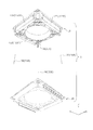
- FIGS. 11 and 12 are exploded perspective views of the OIS fixing unit 20.
- 11 is an upper perspective view
- FIG. 12 is a lower perspective view.
- the OIS fixing unit 20 includes a base 21, a sensor substrate 22, a coil substrate 23, an XY position detection unit 24, and the like.
- the base 21 is a square member in plan view, and has a circular opening 21a at the center.
- the base 21 has positioning bosses 21b at positions corresponding to the positioning holes 23c of the coil substrate 23 and the positioning holes 22b of the sensor substrate 22 at the peripheral edge of the opening 21a.
- the base 21 has a recess 21c at a position corresponding to the control terminal 22c of the sensor substrate 22 at the periphery.
- the recess 21c has a tapered shape that expands outwards downward.
- the base 21 has a hall element accommodating portion 21d that accommodates the hall elements 24A and 24B and a terminal accommodating portion 21e that accommodates the power supply terminal 22d of the sensor substrate 22 at the periphery of the opening 210a.
- the coil substrate 23 is a square substrate in plan view like the base 21 and has a circular opening 23a in the center.
- the coil substrate 23 has notches 23b at four corners. Further, the coil substrate 23 has positioning holes 23c at two locations intersecting the diagonal direction at the peripheral edge of the opening 23a.
- the coil substrate 23 has an OIS coil portion 231 at a position facing the magnet portion 122 in the optical axis direction.
- the OIS coil portion 231 includes three OIS coil portions 231A to 231C corresponding to the magnets 122A to 122C.
- the magnet portion 122 and the OIS coil portion 231 constitute an OIS voice coil motor.
- the sensor substrate 22 is a square substrate in plan view like the base 21 and has a circular opening 22a in the center.
- the sensor substrate 22 has a positioning hole 22b at a position corresponding to the positioning hole 23c of the coil substrate 23 at the periphery of the opening 22a.
- the sensor substrate 22 has terminals 22c formed by bending downward on two sides along the Y direction.
- the terminal 22c is electrically connected to an imaging unit (not shown).
- the sensor substrate 22 has power supply terminals 22d for supplying power to the coil portion 231 for OIS at two places intersecting the diagonal direction of the inner peripheral edge of the opening 22a.
- the sensor substrate 22 has wire fixing holes 22e into which the other end (lower end) of the suspension wire 30 is inserted at the four corners.
- the sensor substrate 22 is for a power supply line (not shown) for supplying power to the OIS movable unit 10 (AF control unit 16) and the OIS coil unit 231, and for detection signals output from the XY position detection units 24A and 24B. Signal lines (not shown), and a control signal signal line (not shown) for controlling the autofocus operation in the OIS movable unit 10.
- XY position detection units 24A and 24B that detect the position of the OIS movable unit 10 on the XY plane are arranged.
- the position detectors 24A and 24B are, for example, Hall elements that detect a magnetic field using the Hall effect (hereinafter referred to as “Hall elements 24A and 24B”).
- Hall elements 24 ⁇ / b> A and 24 ⁇ / b> B are arranged at substantially the center of two adjacent sides of the lower surface of sensor substrate 22.
- the position of the OIS movable unit 10 in the XY plane can be specified by detecting the magnetic field formed by the magnet unit 122 with the Hall elements 24A and 24B.
- a position detection magnet may be arranged in the OIS movable unit 10.
- the coil substrate 23 and the sensor substrate 22 are bonded together by soldering. As a result, the OIS coil portion 231 and the power supply line (not shown) of the sensor substrate 22 are electrically connected.
- the positioning hole 23c of the OIS coil substrate 23 and the positioning hole 22b of the sensor substrate 22 are inserted into the positioning boss 21b of the base 21, and the OIS coil substrate 23 and the sensor substrate 22 are placed on the base 21.
- the terminal 22 c of the sensor substrate 22 is engaged with the recess 21 c of the base 21, whereby the OIS coil substrate 23 and the sensor substrate 22 are fixed to the base 21.
- one ends of the signal suspension wires 31A and 31B are inserted into the wire connection portions 174c and 173c of the signal lines 174 and 173, respectively, and are fixed by soldering.
- One ends of the power supply suspension wires 32A and 32B are inserted into the wire connection portions 172c and 171c of the AF power supply lines 172 and 171 and fixed by soldering.
- the suspension wire 30 is electrically connected to the AF power supply lines 171 and 172 and the signal lines 173 and 174.
- the other end (lower end) of the suspension wire 30 is inserted into the wire fixing hole 22e of the sensor substrate 22 and fixed by soldering. Thereby, the suspension wire 30 and the power supply line and signal line of the sensor substrate 22 are electrically connected. That is, power supply and operation control to the AF control unit 16 can be performed via the suspension wire 30 and the upper elastic support member 13.
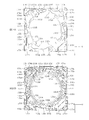
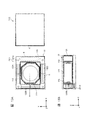
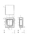
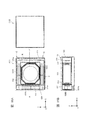
- FIGS. 13A and 13B are diagrams for explaining the arrangement position of the magnet unit 122 of the lens driving device 1 according to the present embodiment.
- 13A is a plan view of the lens driving device 1
- FIG. 13B is a cross-sectional view of the lens driving device 1 taken along the A-A 'axis.
- OC2 in FIG. 13A represents another lens driving device of the adjacent rear camera.
- the magnets 122A to 122C are arranged on three sides other than one side adjacent to the other lens driving device among the four sides of the rectangular outer edge of the magnet holder 121.
- three of the four sides of the outer edge portion are set as the magnet arrangement portion Q, and one side adjacent to the other lens driving device is set as the magnet non-placement portion R where the magnet 122 is not arranged.
- the + X direction of the two sides of the outer edge of the magnet holder 121 facing the X direction corresponds to the magnet non-arranged portion R
- the ⁇ X direction corresponds to the magnet disposed portion Q
- two sides facing the Y direction of the outer edge portion of the magnet holder 121 correspond to the magnet arrangement portion Q.
- the magnet 122B is disposed on the side facing the magnet non-arranged portion R
- the magnets 122A and 122C are disposed on two sides adjacent to the magnet non-arranged portion R.
- the magnets 122A to 122C are, for example, rectangular parallelepiped permanent magnets.
- the magnets 122A to 122C are commonly used for AF and OIS, and a magnetic field that crosses the AF coil portion 112 in the radial direction and for OIS.
- a magnetic field that crosses the coil portions 231A to 231C in the optical axis direction is formed.
- the OIS coil unit 231 is energized. Specifically, in the OIS drive unit, the energization current of the OIS coil unit 231 is based on a detection signal from a shake detection unit (not shown, for example, a gyro sensor) so that the shake of the camera module A is canceled out. Is controlled. At this time, the oscillation of the OIS movable unit 10 can be accurately controlled by feeding back the detection results of the XY position detection units 24A and 24B.
- a shake detection unit not shown, for example, a gyro sensor
- the direction of the Lorentz force is a direction (Y direction or X direction) orthogonal to the magnetic field direction (Z direction) and the current direction (X direction or Y direction) in the long side portion of the OIS coil portion 231. Since the OIS coil portion 231 is fixed, a reaction force acts on the magnet portion 122. This reaction force becomes the driving force of the voice coil motor for OIS, and the OIS movable portion 10 having the magnet portion 122 swings in the XY plane, and shake correction is performed.
- the AF coil unit 112 When automatic focusing is performed in the lens driving device 1, the AF coil unit 112 is energized.
- the energization current in the AF coil unit 112 is controlled by the AF control unit 16 (control IC 161).
- the control IC 161 performs AF based on a control signal supplied via the suspension wires 31A and 31B and the signal lines 174 and 173 and a detection result by a Hall element (not shown) built in the control IC 161.
- the energization current to the coil unit 112 is controlled.
- the direction of the Lorentz force is a direction (Z direction) orthogonal to the direction of the magnetic field (X direction or Y direction) and the direction of the current flowing in the AF coil section 112 (Y direction or X direction). Since the magnet portion 122 is fixed, a reaction force acts on the AF coil portion 112. This reaction force becomes the driving force of the voice coil motor for AF, and the AF movable portion 11 having the AF coil portion 112 moves in the optical axis direction, and focusing is performed.
- closed loop control is performed based on the detection signal of the Hall element built in the control IC 161. According to the closed loop control method, it is not necessary to consider the hysteresis characteristics of the voice coil motor, and it is possible to directly detect that the position of the AF movable portion 11 is stable. Furthermore, automatic focusing of the image plane detection method can also be supported. Therefore, the response performance is high, and the speed of the automatic focusing operation can be increased.
- the AF movable portion 11 is suspended between the infinity position and the macro position by the upper leaf springs 131 and 132 and the lower leaf spring 14 (hereinafter referred to as “reference state”). "). That is, in the OIS movable portion 10, the AF movable portion 11 (lens holder 111) is positioned with respect to the AF fixing portion 12 (magnet holder 121) by the upper leaf springs 131 and 132 and the lower leaf spring 14. Elastically supported to be displaceable on both sides in the Z direction.
- the direction of the current is controlled according to whether the AF movable unit 11 is moved from the reference state to the macro position side or to the infinity position side. Further, the magnitude of the current is controlled according to the moving distance of the AF movable unit 11.
- the lower surface of the first stopper portion 111h of the lens holder 111 approaches the upper surface of the magnet portion 122 and finally comes into contact. That is, the movement toward the infinity position side is restricted by the lower surface of the first stopper portion 111 h of the lens holder 111 and the upper surface of the magnet portion 122.
- the arrangement position of the magnet part 122 is the magnet arrangement part Q for three sides of the substantially rectangular four sides and the magnet non-arrangement part R for one side.
- the magnet arrangement part Q for three sides of the substantially rectangular four sides and the magnet non-arrangement part R for one side.
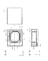
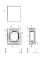
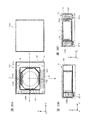
- FIG. 14A and 14B are diagrams illustrating an example of the configuration of the lens driving device 1 according to the present embodiment.
- 14A is a plan view
- FIG. 14B is a cross-sectional view along the A-A ′ axis in FIG. 14A.
- the lens holder 111 is supported at a position displaced toward the magnet non-arranged portion R side of the magnet holder 121, and the magnet 122B is compared to the magnets 122A and 122C.
- This is different from the first embodiment in that it has a large shape.
- description is abbreviate
- the OIS fixing unit 20 is omitted in FIGS. 14A and 14B.
- the OIS coil portions 231A to 231C of the OIS fixing portion 20 are disposed at positions separated from the magnets 122A to 122C in the optical axis direction (hereinafter, other components). The same applies to the above embodiment).
- the OIS movable portion 10 (the magnet holder 121 and the lens holder 111) loses the weight balance among the four sides in the XY plane, and thus an unnecessary resonance phenomenon occurs during shake correction. There is a risk.
- the OIS movable portion 10 is supported by a plurality of suspension wires 30 so as to be swingable, a resonance phenomenon is likely to occur.
- the lens driving device 1 eliminates these states by the above configuration. That is, the lens holder 111 is supported at a position displaced toward the magnet non-arranged portion R side of the magnet holder 121, so that the weight balance of the OIS movable portion 10 as a whole is made uniform among the four sides. The moving state of can be stabilized.
- the magnet 122B maintains the above weight balance by utilizing the space formed when the lens holder 111 is disposed at a position displaced toward the magnet non-arranged portion R side of the magnet holder 121. While increasing the size. As a result, the magnetic field to the coil portion 231B for OIS to be applied from the magnet 122B can be increased, and the driving force in the X direction can be increased. Further, it is possible to enhance the magnetic field applied to the AF coil unit 112 that acts from the magnet 122B, and to increase the driving force in the optical axis direction.
- increasing the size of the magnet 122B means increasing the area for generating a magnetic field or increasing the magnetization region so that the magnetic field in the X direction applied to the coil portion 231B for OIS is enhanced. means.
- the lens driving device 1 similarly to the first embodiment, the magnetic interference with respect to other lens driving devices is suppressed, and the OIS movable unit is further used for shake correction. Ten moving states can be stabilized. In addition, at that time, by increasing the size of the magnet 122B, the driving force in the X direction where the magnet non-arranged portion R exists can be increased.
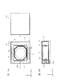
- 15A and 15B are diagrams illustrating an example of the configuration of the lens driving device 1 according to the present embodiment.
- 15A is a plan view
- FIG. 15B is a cross-sectional view along the A-A ′ axis in FIG. 15A.
- the lens driving device 1 when the AF coil unit 112 and the magnets 122A to 122C pass current through the AF coil unit 112, the driving force generated in the AF coil unit 112 from each direction is reduced.
- the resultant force vector is configured to coincide with the optical axis direction.
- the driving force generated at the position of the AF coil portion 112 in the + X direction when the current is passed through the AF coil portion 112 is eliminated, and thus the entire AF coil portion 112 is generated.
- the resultant force vector of the driving force may be in a direction inclined in the + X direction from the optical axis direction (hereinafter referred to as “AF tilt”).
- AF tilt When AF tilt occurs, autofocus becomes difficult.
- the lens driving device 1 employs the following configuration in order to prevent AF tilt.
- Both the magnets 122A and 122C on the Y direction side of the two sides are arranged at positions shifted to the magnet non-arrangement portion R side with respect to the center of the lens holder 111.
- the AF coil portion 112 has such a shape that a region facing the magnet 122B on the X direction side facing the magnet non-arranged portion R becomes small.
- the AF coil section 112 has a hexagonal shape that is deformed from a rectangular shape to a convex shape toward the magnet 122B in plan view.
- the AF coil portion 112 has a shape in which the region facing the magnet 122B and the region facing the magnets 122A and 122C have substantially the same length.
- the driving force due to the interaction between the energizing current of the AF coil unit 112 and the magnetic field generated by the magnets 122A, 122B, and 122C can be balanced.
- the shape of 112 may be the same as in the first embodiment.
- the magnetic interference with respect to other lens driving devices is suppressed, and further, AF tilt is generated during autofocusing. Can be suppressed.
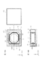
- FIGS. 16A and 16B are diagrams illustrating an example of the configuration of the lens driving device 1 according to the present embodiment.
- 16A is a plan view
- FIG. 16B is a cross-sectional view along the A-A ′ axis in FIG. 16A.
- the lens driving device 1 according to the present embodiment is different from the first embodiment in that a non-magnetic material balance weight 123 is disposed in the magnet non-arrangement portion R.
- the lens driving device 1 prevents an unnecessary resonance phenomenon during shake correction by the above configuration.
- the balance weight 123 is provided for weight balance with the other three side magnets 122A to 122C, and is arranged in the magnet non-arrangement portion R.
- the balance weight 123 for example, a nonmagnetic material having substantially the same weight and shape as the magnet portion 122 can be used.
- the weight balance of the OIS movable unit 10 as a whole can be made uniform among the four sides, so that the OIS movable unit 10 can be further corrected during shake correction while suppressing magnetic interference with other lens driving devices.
- the movement state of can be stabilized.
- FIG. 17A and FIG. 17B are diagrams showing an example of the configuration of the lens driving device 1 according to the present embodiment.
- 17A is a plan view
- FIG. 17B is a cross-sectional view along the A-A ′ axis in FIG. 17A.
- the magnetized region in the cross section orthogonal to the longitudinal direction is divided into two parts, the optical axis direction and the radial direction, as the magnet 122B on the side facing the magnet non-arrangement portion R, and adjacent to each other.
- This is different from the first embodiment in that a double-sided quadrupole magnet in which magnetized regions are magnetized by different magnetic poles is employed.
- the lens driving device 1 according to the present embodiment prevents AF tilt by the above configuration.
- the magnetized region in the substantially rectangular parallelepiped XZ cross section is divided into two in each of the X direction and the Z direction. Then, the magnetized region of the magnet 122B on the + X side is magnetized to the S pole and the N pole in order from the lower side, and the magnetized region on the ⁇ X side is magnetized to the N pole and the S pole in order from the lower side. Yes.
- the magnet 122B has a region facing the AF coil 112 near the center of the magnetized region divided in the Z direction, and a region facing the + Y side winding of the OIS coil 231B and the ⁇ Y side.
- the magnetic poles are arranged so as to be different from the regions facing the windings of the magnetic poles.
- the magnetic interference with respect to other lens driving devices is suppressed, and further, AF tilt is generated during autofocusing. Can be suppressed.
- FIGS. 18A and 18B are diagrams illustrating an example of the configuration of the lens driving device 1 according to the present embodiment.
- 18A is a plan view
- FIG. 18B is a cross-sectional view along the A-A ′ axis in FIG. 18A.
- the lens driving device 1 according to the present embodiment is different from the first embodiment in that a yoke 124 is interposed between the magnet 122B at a position facing the magnet non-arrangement portion R and the AF coil portion 112.
- the lens driving device 1 according to the present embodiment prevents AF tilt by this configuration.
- the yoke 124 is disposed in the magnet holder 121 so as to be interposed between the magnet 122B and the AF coil portion 112.
- the yoke 124 is a magnetic material, and shields the magnetic field that acts on the AF coil portion 112 from the magnet 122B.
- the AF coil part 112 has a driving force mainly due to the action of the magnetic field generated by the magnet 122A and the magnet 122C during autofocus. Arise. In other words, the moment acting on the AF coil portion 112 is canceled out. By doing so, the resultant vector of the driving force acting on the AF movable portion 11 (lens holder 111) is made to coincide with the optical axis, and AF tilt is prevented.
- the magnetic interference with respect to other lens driving devices is suppressed, and further, AF tilt is generated during autofocusing. Can be suppressed.
- 19A and 19B are diagrams illustrating an example of the configuration of the lens driving device 1 according to the present embodiment.
- 19A is a plan view
- FIG. 19B is a cross-sectional view along the A-A ′ axis of FIG. 19A.
- the lens driving device 1 according to the present embodiment is different from the first embodiment in that a yoke 124 is disposed between the magnet 122B and the AF coil portion 112, as in the sixth embodiment.
- the lens driving device 1 according to the present embodiment prevents AF tilt by this configuration.
- the yoke 124 is disposed between the magnet 122B and the AF coil portion 112, and is extended from the position and disposed on two sides adjacent to the magnet non-arrangement portion R.
- the magnets 122A and 122C are disposed along the outer edge of the magnet holder 121 so as to surround the outer periphery.
- the AF coil part 112 has a driving force mainly due to the action of the magnetic field generated by the magnet 122A and the magnet 122C during autofocus. Arise.
- the resultant vector of the driving force acting on the AF movable portion 11 (lens holder 111) coincides with the optical axis, so that AF tilt can be prevented.
- the magnet holder 121 is supported by the four suspension wires 30 in order to balance the load acting on the members (the upper elastic support member 13 and the coil substrate 23) that fix the four suspension wires 30.
- the support position is asymmetric between two on the + X side in the X direction and two on the ⁇ X side. More specifically, the support position of the two suspension wires 30 on the + X side is set closer to the center side of the magnet holder 121 than the support position of the two suspension wires 30 on the ⁇ X side.
- the magnetic interference with respect to other lens driving devices is suppressed, and further, AF tilt is generated during autofocusing. Can be suppressed.
- 20A to 20C are diagrams showing an example of the configuration of the lens driving device 1 according to the present embodiment.
- 20A is a plan view
- FIG. 20B is a cross-sectional view along the A-A ′ axis of FIG. 20A
- FIG. 20C is a cross-sectional view along the B-B ′ axis of FIG. 20A.
- the lens driving device 1 according to the present embodiment is the first in that the AF coil unit 112 is configured by two coil units 112A and 112B arranged at positions facing the magnets 122A and 122C of the lens holder 111. This is different from the embodiment.
- the lens driving device 1 according to the present embodiment prevents AF tilt by this configuration.
- the AF coil portions 112A and 112B are both planar coils, and are wound in the XZ plane and have a flat plate shape extending in the X direction and the Z direction.
- the AF coil portions 112A and 112B are arranged on the lens holder 111 so as to face the magnets 122A and 122C, respectively.
- the magnets 122A and 122C each have a structure in which the magnetized region in the YZ section is divided into two in the Y direction and the Z direction, and adjacent magnetized regions are magnetized by different magnetic poles.
- the magnet 122A is a magnetized region of magnetic poles in which the region facing the + Z side winding of the AF coil portion 112A and the region facing the ⁇ Z side winding are different, and the magnet 122A of the OIS coil portion 231A
- the region facing the + Y side winding and the region facing the ⁇ Y side winding are arranged so as to be magnetized regions of different magnetic poles.
- the magnet 122C is a magnetized region of magnetic poles in which the region facing the + Z side winding of the AF coil unit 112B and the region facing the ⁇ Z side winding are different, and the OIS coil unit 231C.
- the region facing the + Y side winding and the region facing the ⁇ Y side winding are arranged so as to be magnetized regions of different magnetic poles.
- the magnetic interference with respect to other lens driving devices is suppressed, and further, AF tilt is generated during autofocusing. Can be suppressed.
- the driving force changes according to the position of the lens holder 111 in the optical axis direction, and the linearity of the driving force is ensured. It is hard to do. From this point of view, it is more desirable that the AF coil portion 112 is configured to wind the outer peripheral surface of the lens holder 111 as in the above embodiments.
- a smartphone has been described as an example of a camera mounting device including the camera module A.
- the lens driving device 1 according to the present invention can be applied to various information devices.
- the present invention can be applied to a notebook computer, a portable game machine, an in-vehicle device with a camera, and the like.
- 21A and 21B are diagrams showing an example in which the camera module A is applied to an in-vehicle camera module VC (Vehicle Camera).
- VC Vehicle Camera
- FIG. 21A is a front view of the automobile V, and shows a state where the in-vehicle camera module VC is attached to the windshield with the lens portion facing in the traveling direction.
- FIG. 21B is a rear view of the automobile V, and shows a state where the in-vehicle camera module VC is attached to the vehicle body with the lens portion facing rearward in the traveling direction.
- the in-vehicle camera module VC can be used for a drive recorder, a collision avoidance control, an automatic driving control, and the like.
- the magnet holder 121 has a substantially rectangular outer shape in plan view, but may have a hexagonal or octagonal outer shape in plan view.
- the magnet unit 122 has a magnet arrangement unit Q in which magnets are arranged on three sides of the substantially rectangular four sides in plan view. The other side is a magnet non-arranged portion R where no magnet is arranged.
- the suspension wire is used as an example of the OIS support member 30 that supports the lens holder 111 so as to be movable in the XY directions.
- the OIS support member 30 may be other than the suspension wire.
- a plate spring that supports the lens holder 111 from both sides in the X direction and a plate spring that supports the lens holder 111 from both sides in the Y direction may be used.
- a mode in which a leaf spring is used is shown as an example of the AF support members 13 and 14 that support the lens holder 111 so as to be movable in the optical axis direction.
- the AF support members 13 and 14 may be other than a leaf spring, and for example, a roller bearing that supports the lens holder 111 so as to be movable in the optical axis direction may be used.
- a first coil portion 112 disposed around a lens holder that holds the lens portion, a magnet portion 122 disposed radially away from the first coil portion 112, and the magnet portion 122.
- First support members 13 and 14 that support the autofocus movable unit 11 including the first coil unit 11 so as to be movable in the optical axis direction with respect to the autofocus fixed unit 12 including An autofocus drive unit that automatically focuses using a driving force of a voice coil motor composed of the coil unit 112 and the magnet unit 122, and the magnet disposed in the autofocus drive unit Part 122, second coil part 231 spaced apart from the magnet part 122 in the optical axis direction, and second coil part 231.
- a second support member 30 that supports the shake correction movable part 10 including the magnet part 122 with respect to the shake correction fixing part 20 so as to be movable in a plane orthogonal to the optical axis, and the second coil part. 231 and a shake correction drive unit that performs shake correction using a drive force of a voice coil motor configured by the magnet unit 122, and the magnet unit 122 is planarly viewed.
- the first magnets 122A and 122C are disposed on two opposite sides of the substantially rectangular four sides, and the second magnet 122B is disposed on the other side, and the second magnet 122B is opposed to the second magnet 122B.
- the side to be disclosed discloses the lens driving device 1 having a magnet non-arrangement portion R in which no magnet is arranged.
- this lens driving device 1 even if it is arranged adjacent to another lens driving device 1, one side adjacent to the other lens driving device 1 can be set as a magnet non-arrangement portion R. It is possible to prevent the magnet portion 122 held by the magnetic lens 122 from causing magnetic interference to the other lens driving device 1.
- the lens holder 111 is arranged to be deviated to the magnet non-arranged portion R side inside the magnet holder 121 that holds the magnet portion 122. Also good.
- the lens driving device 1 since the weight balance of the OIS movable unit 10 as a whole can be made uniform among the four sides, unnecessary resonance is prevented and the moving state at the time of shake correction is stabilized. It becomes possible.
- the second magnet 122B in the lens driving device 1 may have a larger size than the first magnets 122A and 122C.
- the lens driving device 1 it is possible to increase the driving force in the X direction where the magnet non-arrangement portion R exists at the time of shake correction.
- first magnets 122A and 122C in the lens driving device 1 may be arranged so as to be deviated toward the magnet non-arrangement portion R side.
- the resultant vector of the driving force with respect to the first coil portion 112 can be made to coincide with the optical axis of the lens, thereby preventing the occurrence of AF tilt.
- the first coil portion 112 has substantially the same length in the area facing the second magnet and the area facing the first magnets 122A and 122C. It may exhibit a shape that becomes.
- the resultant vector of the driving force with respect to the first coil portion 112 can be made to coincide with the optical axis of the lens, thereby preventing the occurrence of AF tilt.
- a non-magnetic material balance weight may be disposed in the magnet non-arrangement portion R.
- the lens driving device 1 since the weight balance of the OIS movable unit 10 as a whole can be made uniform among the four sides, unnecessary resonance is prevented and the moving state at the time of shake correction is stabilized. It becomes possible.
- the second magnet 122B in the lens driving device 1 has a magnetized region in a cross section perpendicular to the longitudinal direction divided in two in the optical axis direction and the radial direction, and the adjacent magnetized regions are different from each other. It may be magnetized.
- the lens driving device 1 since the magnet as described above is used as the magnet 122B on the side facing the magnet non-arrangement portion R, the magnetic field acting on the AF coil portion 112 from the magnet 122B is used. Generation of driving force can be suppressed, and occurrence of AF tilt can be prevented.
- the lens driving device 1 may further include a yoke 124 interposed between the second magnet 122B and the first coil portion 112.
- the yoke 124 limits the magnetic field that acts on the AF coil portion 112 from the second magnet 122B, thereby preventing the occurrence of AF tilt.
- the yoke 124 extends from between the second magnet 122B and the first coil portion 112, and surrounds the first magnets 122A and 122C from the outer periphery. It may be disposed along the outer edge of the magnet holder 121.
- the yoke 124 limits the magnetic field that acts on the AF coil portion 112 from the magnet 122B on the side facing the non-magnet placement portion R, thereby preventing the occurrence of AF tilt. it can.
- the yoke 124 can perform magnetic shielding from the magnets 122 ⁇ / b> A and 122 ⁇ / b> C to the outside of the lens driving device 1 and can increase the strength of the magnet holder 121.
- the lens driving device according to the present disclosure can be suitably used for a dual camera.
Landscapes
- Physics & Mathematics (AREA)
- General Physics & Mathematics (AREA)
- Optics & Photonics (AREA)
- Engineering & Computer Science (AREA)
- Multimedia (AREA)
- Signal Processing (AREA)
- Lens Barrels (AREA)
- Adjustment Of Camera Lenses (AREA)
Abstract
第1のコイル部112とマグネット部122とで構成されるボイスコイルモーターの駆動力を利用して自動的にピント合わせを行うオートフォーカス用駆動部と、第2のコイル部231と前記マグネット部122で構成されるボイスコイルモーターの駆動力を利用して振れ補正を行う振れ補正用駆動部と、を備えるレンズ駆動装置1であって、前記マグネット部122は、平面視で、略矩形状の四辺のうちの対向する二辺に配置される第1のマグネット122A、122Cと他の一辺に配置される第2のマグネット122Bとを有し、前記第2のマグネット122Bが対向する辺は、マグネットが配置されないマグネット非配置部Rとなっている。
Description
本発明は、レンズ駆動装置、カメラモジュール及びカメラ搭載装置に関する。
一般に、スマートフォン等の携帯端末には、小型のカメラモジュールが搭載されている。このようなカメラモジュールには、被写体を撮影するときのピント合わせを自動的に行うオートフォーカス(Auto Focus:以下「AF」と略称する)機能、及び撮影時に生じる振動を光学的に補正する振れ補正(Optical Image Stabilization:以下「OIS」と略称する)機能を有するレンズ駆動装置が適用される。
例えば、特許文献1、特許文献2には、マグネットとコイルとで構成するボイスコイルモーターによって、AF機能及びOIS機能を実現することが記載されている。
ところで、近年、デュアルカメラのように、複数のレンズ駆動装置を有するカメラモジュールの実用化が進められている。デュアルカメラは、焦点距離の異なる2枚の画像を同時に撮像できたり、静止画像と動画像を同時に撮像できたりするなど、利用シーンに応じて様々な可能性を有している。
しかしながら、デュアルカメラにおいては、二つのレンズ駆動装置が隣接して配置される。そのため、それぞれに、上記したAF機能やOIS機能を実現するためのマグネットやコイルを設けた場合、一方のレンズ駆動装置のマグネットからの磁気干渉によって、他方のレンズ駆動装置の動作が不安定になるおそれがある。例えば、特許文献1や特許文献2のレンズ駆動装置では、当該レンズ駆動装置の外周部分にマグネットが配置されており、当該マグネットが発生する磁界によって、他のレンズ駆動装置のコイルに磁界を作用させ、AF時やOIS時の動作が不安定になるおそれがある。
他方、二つのレンズ駆動装置同士を磁気干渉が生じない程度まで離間させた場合、カメラモジュールの小型化が阻害され、製品化する上で不利である。
本発明は、上記の問題点に鑑みてなされたもので、隣接する他のレンズ駆動装置に対する磁気干渉を抑制できる、デュアルカメラの用途に好適なレンズ駆動装置、カメラモジュール及びカメラ搭載装置を提供することを目的とする。
前述した課題を解決する主たる本発明は、レンズ部を保持するレンズホルダーの周囲に配置される第1のコイル部と、前記第1のコイル部に対して径方向に離間して配置されるマグネット部と、前記マグネット部を含むオートフォーカス固定部に対して前記第1のコイル部を含むオートフォーカス可動部を光軸方向に移動可能に支持する第1の支持部材と、を有し、前記第1のコイル部と前記マグネット部とで構成されるボイスコイルモーターの駆動力を利用して自動的にピント合わせを行うオートフォーカス用駆動部と、前記オートフォーカス用駆動部に配置される前記マグネット部と、前記マグネット部に対して光軸方向に離間して配置される第2のコイル部と、前記第2のコイル部を含む振れ補正固定部に対して前記マグネット部を含む振れ補正可動部を光軸直交面内で揺動可能に支持する第2の支持部材と、を有し、前記第2のコイル部と前記マグネット部で構成されるボイスコイルモーターの駆動力を利用して振れ補正を行う振れ補正用駆動部と、を備えるレンズ駆動装置であって、前記マグネット部は、平面視で、略矩形状の四辺のうちの対向する二辺に配置される第1のマグネットと他の一辺に配置される第2のマグネットとを有し、前記第2のマグネットが対向する辺は、マグネットが配置されないマグネット非配置部となっているレンズ駆動装置である。
本発明に係るレンズ駆動装置よれば、隣接する他のレンズ駆動装置に対する磁気干渉を抑制することができる。
(第1の実施形態)
以下、図1~図13を参照して、第1の実施形態に係るレンズ駆動装置1、及び当該レンズ駆動装置1を搭載するカメラモジュールAの構成の一例について説明する。
以下、図1~図13を参照して、第1の実施形態に係るレンズ駆動装置1、及び当該レンズ駆動装置1を搭載するカメラモジュールAの構成の一例について説明する。
図1A、図1Bは、本実施形態に係るカメラモジュールAを搭載するスマートフォンMを示す図である。図1AはスマートフォンMの正面図であり、図1BはスマートフォンMの背面図である。
スマートフォンMは、二つの隣接する背面カメラOC1、OC2からなるデュアルカメラを有する。少なくとも一方の背面カメラOC1に、本実施形態に係るカメラモジュールAが適用される。カメラモジュールAは、上記したAF機能及びOIS機能を有している。
尚、他方の背面カメラOC2は、背面カメラOC1と同様に、本実施形態に係るカメラモジュールAと同様の構成が適用されてもよいし、ボイスコイルモーターを有する他の構成が適用されてもよい。
図2は、カメラモジュールAの外観斜視図である。図3、図4は、カメラモジュールAの分解斜視図である。図3は上方斜視図であり、図4は下方斜視図である。
図2~図4に示すように、本実施の形態では、直交座標系(X、Y、Z)を使用して説明する。後述する図においても共通の直交座標系(X、Y、Z)で示している。
カメラモジュールAは、スマートフォンMで実際に撮影が行われる場合に、X方向が上下方向(又は左右方向)、Y方向が左右方向(又は上下方向)、Z方向が前後方向となるように搭載される。すなわち、Z方向が光軸方向であり、図中上側が光軸方向受光側(「マクロ位置側)ともいう)、下側が光軸方向結像側(「無限遠位置側」ともいう)となる。また、Z軸に直交するX方向及びY方向を「光軸直交方向」と称する。
カメラモジュールAは、AF機能及びOIS機能を実現するレンズ駆動装置1、円筒形状のレンズバレルにレンズが収容されてなるレンズ部(図示略)、レンズ部により結像された被写体像を撮像する撮像部(図示略)、及び全体を覆うカバー2等を備える。
カバー2は、光軸方向から見た平面視で正方形状の有蓋四角筒体であり、上面に円形の開口2aを有する。この開口2aからレンズ部(図示略)が外部に臨む。カバー2は、レンズ駆動装置1のOIS固定部20のベース21(図11、図12参照)に固定される。
撮像部(図示略)は、撮像素子(図示略)を有し、レンズ駆動装置1の光軸方向結像側に配置される。撮像素子(図示略)は、例えばCCD(Charge-Coupled device)型イメージセンサー、CMOS(Complementary metal oxide semiconductor)型イメージセンサー等により構成される。撮像素子(図示略)は、レンズ部(図示略)により結像された被写体像を撮像する。
図5、図6は、レンズ駆動装置1の分解斜視図である。図5は上方斜視図であり、図6は下方斜視図である。図5、図6に示すように、レンズ駆動装置1は、OIS可動部10、OIS固定部20、及びOIS用支持部材30等を備える。
OIS可動部10は、OIS用ボイスコイルモーターを構成するOIS用マグネット部を有し、振れ補正時にXY平面内に揺動する部分である。OIS固定部20は、OIS用ボイスコイルモーターを構成するOIS用コイル部231を有し、OIS用支持部材30を介してOIS可動部10を支持する部分である。すなわち、レンズ駆動装置1のOIS用駆動部には、ムービングマグネット方式が採用されている。OIS可動部10は、AF用駆動部(AF可動部11及びAF固定部12、図7、図8参照)を含む。
OIS可動部10は、OIS固定部20に対して光軸方向受光側に離間して配置され、OIS用支持部材30によってOIS固定部20と連結される。具体的には、OIS用支持部材30は、Z方向に沿って延在する4本のサスペンションワイヤーで構成される(以下「サスペンションワイヤー30」と称する)。サスペンションワイヤー30の一端(上端)はOIS可動部10(上側弾性支持部材13、図7、図8参照)に固定され、他端(下端)はOIS固定部20(コイル基板23、図11、図12参照)に固定される。OIS可動部10は、サスペンションワイヤー30によって、XY平面内で揺動可能に支持される。
本実施の形態では、4本のサスペンションワイヤー30のうち、サスペンションワイヤー31A、31Bは制御IC161(図9参照)に制御信号を伝達する信号経路として使用され、サスペンションワイヤー32A、32Bは制御IC161の給電経路として使用される(以下「信号用サスペンションワイヤー31A、31B」、「給電用サスペンションワイヤー32A、32B」と称する)。
図7、図8は、OIS可動部10の分解斜視図である。図7は上方斜視図であり、図8は下方斜視図である。
図7、図8に示すように、OIS可動部10は、AF可動部11、AF固定部12、AF用支持部材13、14、AF用電源ライン171、172、及び信号ライン173、174等を備える。
AF可動部11は、AF用ボイスコイルモーターを構成するAF用コイル部112を有し、ピント合わせ時に光軸方向に移動する部分である。AF固定部12は、マグネット部122(AF用マグネット部)を有し、AF用支持部材13、14を介してAF可動部11を支持する部分である。すなわち、レンズ駆動装置1のAF用駆動部には、ムービングコイル方式が採用されている。
AF可動部11は、AF固定部12に対して径方向内側に離間して配置され、AF用支持部材13、14によってAF固定部12と連結される。AF用支持部材13は、AF固定部12に対してAF可動部11を上側で支持する上側弾性支持部材であり(以下「上側弾性支持部材13」と称する)、AF用支持部材14は、AF固定部12に対してAF可動部11を下側で支持する下側弾性支持部材である(以下「下側弾性支持部材14」と称する)。
AF可動部11は、レンズホルダー111、AF用コイル部112、及び位置検出用磁石15A、15Bを有する。
レンズホルダー111は、筒状のレンズ収容部111a、及びレンズ収容部111aから径方向外側に突出する平面視で略八角形状のフランジ部111b、111cを有するフランジ部111b、111cで挟まれる部分(以下「コイル巻線部」と称する)に、AF用コイル部112が巻線される。フランジ部111bの上面は、AF可動部11の光軸方向受光側への移動を規制するための被係止部となる。
レンズホルダー111は、レンズ収容部111aの上部外周において、X方向及びY方向(以下「十字方向」と称する)を45°回転した方向(以下「対角方向」と称する)と交差する4つの部分に、上側弾性支持部材13を固定するための上バネ固定部111dを有する。レンズホルダー111は、レンズ収容部111aの外周に沿って、第1のストッパー部111hを有する。第1のストッパー部111hの下面がAF可動部11の光軸方向結像側への移動を規制するための被係止部となる。
レンズホルダー111は、4つの上バネ固定部111dのうちの対角に位置する2つの上バネ固定部111dから径方向外側に突出する絡げ部111eを有する。レンズホルダー111は、絡げ部111eが配置されていない2つの上バネ固定部111dに、位置検出用磁石15A、15Bを収容する磁石収容部111fを有する。また、レンズホルダー111は、フランジ部111cの下面において、十字方向と交差する4つの部分に、下側弾性支持部材14を固定するための下バネ固定部111gを有する。
AF用コイル部112は、ピント合わせ時に通電される空芯コイルであり、レンズホルダー111のコイル巻線部の外周面に巻線される。AF用コイル部112の両端は、レンズホルダー111の絡げ部111e、111eに絡げられる。AF用コイル部112の通電電流は制御IC161(図9参照)によって制御される。
位置検出用磁石15A、15Bは、レンズホルダー111の磁石収容部111fに配置される。AF用制御部に対応する側に配置される位置検出用磁石15A(以下「第1の位置検出用磁石15A」と称する)が、実際にAF可動部11の位置検出に用いられる。他方の位置検出用磁石15B(以下「第2の位置検出用磁石15B」と称する)は、AF可動部11の位置検出には用いられないダミー磁石である。第2の位置検出用磁石15Bは、AF可動部11に作用する磁力をバランスさせ、AF可動部11の姿勢を安定させるために配置される。すなわち、第2の位置検出用磁石15Bを配置しない場合、マグネット部122が発生する磁界によってAF可動部11に片寄った磁力が作用し、AF可動部11の姿勢が不安定となるので、第2の位置検出用磁石15Bを配置することにより、これを防止している。
AF固定部12は、マグネットホルダー121、マグネット部122、及びAF用制御部16を有する。
マグネットホルダー121は、正方形状の上部枠体121a、及び上部枠体121aの四隅に垂設される脚部121bを有する。4つの脚部121bは、それぞれ、上部枠体121aの4辺に沿ってマグネット部122を保持するマグネット保持部121cを有する。また、脚部121bは、それぞれ、径方向内側に円弧状に凹むワイヤー挿通部121dを有する。ワイヤー挿通部121dに、サスペンションワイヤー30が配置される(図5、図6参照)。ワイヤー挿通部121dを設けることにより、OIS可動部10が揺動する際に、サスペンションワイヤー30とマグネットホルダー121が干渉するのを回避することができる。
マグネットホルダー121は、上部に、径方向内側に張り出す第2のストッパー部121eを有する。マグネットホルダー121は、レンズホルダー111のレンズ収容部111a、上バネ固定部111d、絡げ部111e、第1のストッパー部111hに対応する部分が切り欠かれた開口を有する。AF可動部11は、マグネットホルダー121の上面よりも光軸方向受光側に移動することができる。AF可動部11が光軸方向受光側に移動するときに、レンズホルダー111のフランジ部111bに第2のストッパー部121eが当接することにより、AF可動部11の光軸方向受光側への移動が規制される。
また、第2のストッパー部121eの上面には、上側弾性支持部材13のアーム部131c、131f、132c、132f(図10参照)が載置される。第2のストッパー部121eには、ダンパー収容部121jが配置される。
マグネットホルダー121は、脚部121bの下面に、下側弾性支持部材14を固定するための下バネ固定部121fを有する。マグネットホルダー121は、上部の四隅に、上側弾性支持部材13を固定するための上バネ固定部121hを有する。
上バネ固定部121hの角部121iは、マグネットホルダー121の上面(上側弾性支持部材13が取り付けられる面)よりも下側に凹んで形成され、上側弾性支持部材13を取り付けたときに、隙間が形成されるようになっている(以下「「ダンパー配置部121i」と称する)。ダンパー配置部121iの頂角部は外側に延出し、円弧状に切り欠かれている。ダンパー配置部121iの円弧状に切り欠かれている部分は、ワイヤー挿通部121dに連通する。
また、マグネットホルダー121は、一つの脚部121bに、AF用制御部16を収容するためのIC収容部121gを有する。
マグネット部122は、3つの直方体状のマグネット122A~122Cを有する。マグネット122A~122Cは、マグネットホルダー121のマグネット保持部121cに、接着により固定される。マグネット122A~122Cは、AF用コイル部112に径方向に横切る磁界が形成されるように着磁される。例えば、マグネット122A~122Cは、内周側がN極、外周側がS極に着磁された永久磁石である。
マグネット部122及びAF用コイル部112によって、AF用ボイスコイルモーターが構成される。本実施の形態では、マグネット部122は、AF用マグネット部とOIS用マグネット部を兼用する。
図9は、AF用制御部16の構成を示す拡大図である。AF用制御部16は、マグネットホルダー121のIC収容部121gに配置される。
AF用制御部16は、制御IC161、制御IC161が実装されるAF用回路基板162、及びコンデンサー(符号略)を有する。
制御IC161は、ホール効果を利用して磁界の変化を検出するホール素子(図示略)を内蔵し、Z位置検出部として機能する。制御IC161は、ホール素子(図示略)の検出方向が光軸方向と一致するように配置される。制御IC161は、主として第1の位置検出用磁石15Aによる磁界の変化を検出する。これにより、光軸方向におけるAF可動部11の位置が検出される。
また、制御IC161は、AF用コイル部112の通電電流を制御するコイル制御部(図示略)を有する。制御IC161は、AF用コイル部112に電気的に接続され、信号用サスペンションワイヤー31A、31B及び信号ライン173、174を介して供給される制御信号及びホール素子による検出結果に基づいて、AF用コイル部112の通電電流を制御する。
AF用回路基板162は、電源出力端子162a、162f、電源入力端子162b、162e、及び信号入力端子162c、162dを有する。電源出力端子162a、162fは上側弾性支持部材13(上側板バネ131、132)に接続され、電源入力端子162b、162eはAF用電源ライン171、172に接続され、信号入力端子162c、162dは信号ライン173、174に接続される。
AF用回路基板162は、電源出力端子162a、162f、電源入力端子162b、162e、及び信号入力端子162c、162dを有する。電源出力端子162a、162fは上側弾性支持部材13(上側板バネ131、132)に接続され、電源入力端子162b、162eはAF用電源ライン171、172に接続され、信号入力端子162c、162dは信号ライン173、174に接続される。
上側弾性支持部材13、AF用電源ライン171、172及び信号ライン173、174は、例えばベリリウム銅、ニッケル銅、ステンレス等で形成される。
図10は、上側弾性支持部材13、AF用電源ライン171、172及び信号ライン173、174の構成を示す平面図である。図10Aは、上側弾性支持部材13、AF用電源ライン171、172及び信号ライン173、174をAF可動部11及びAF固定部12に取り付ける前の状態を示し、図10Bは、取り付けた後の状態を示す。
図10に示すように、上側弾性支持部材13、AF用電源ライン171、172、信号ライン173、174は、全体として平面視で正方形状、すなわちマグネットホルダー121の上部枠体121aと同等の形状を有し、上部枠体121a上に互いに接触しないように配線される。上側弾性支持部材13は、マグネットホルダー121とレンズホルダー111を連結するため、AF用電源ライン171、172及び信号ライン173、174の内側に配置される。上側板バネ131、132、AF用電源ライン171、172及び信号ライン173、174は、例えば一枚の板金をエッチング加工することにより形成される。
上側弾性支持部材13は、AF固定部12に対してAF可動部11を弾性支持する上側板バネ131、132である。上側板バネ131、132は、AF用コイル部112に給電するためのコイル用電源ラインとして機能する。AF用電源ライン171、172は、給電用サスペンションワイヤー32B、32Aに接続され、AF用制御部16(制御IC161)に給電する。信号ライン173、174は、信号用サスペンションワイヤー31B、31Aに接続され、AF用制御部16(制御IC161)に制御信号を供給する。
上側板バネ131は、2つのバネ部131A、131Bを有する。バネ部131Aは、レンズホルダー111に固定されるレンズホルダー固定部131a、マグネットホルダー121に固定されるマグネットホルダー固定部131b、及びレンズホルダー固定部131aとマグネットホルダー固定部131bを連結するアーム部131cを有する。同様に、バネ部131Bは、レンズホルダー固定部131d、マグネットホルダー固定部131e、及びアーム部131fを有する。レンズホルダー固定部131a、131dは、レンズホルダー111のレンズ収容部111aに沿って連結されている。
レンズホルダー固定部131a、131dの固定穴(符号略)が、レンズホルダー111の上バネ固定部111dの位置決めボス(符号略)に挿嵌されることにより、レンズホルダー111に対して上側板バネ131が位置決めされ、固定される。また、マグネットホルダー固定部131b、131eの固定穴(符号略)が、マグネットホルダー121の上バネ固定部121eの位置決めボス(符号略)に挿嵌されることにより、マグネットホルダー121に対して上側板バネ131が位置決めされ、固定される。
アーム部131c、131fは、湾曲形状を有し、AF可動部11が移動するときに弾性変形する。上側板バネ131は、アーム部131c、131fのそれぞれから分岐して延在するダンパー固定部131j、131kを有する。ダンパー固定部131j、131kは、マグネットホルダー121のダンパー収容部121jに配置され、ダンパー材によって埋め込まれる。
上側板バネ131は、マグネットホルダー固定部131bからX方向に沿う一方の周縁に向かって延在する補助固定部131gを有する。補助固定部131gは、マグネットホルダー121の上面に配置され、マグネットホルダー121に対する上側板バネ131の固定状態を補強する。
上側板バネ131は、マグネットホルダー固定部131eからAF用回路基板162に向かって延在する端子接続部131hを有する。端子接続部131hは、AF用制御部16の電源出力端子162aに接続される。上側板バネ131は、レンズホルダー固定部131a、131dの連結部分から分岐して延在するコイル接続部131iを有する。コイル接続部131iの先端部は、U字形状を有する。コイル接続部131iは、AF用コイル部112の一端部と、半田付けにより接続される。すなわち、AF用制御部16とAF用コイル部112は、上側板バネ131を介して電気的に接続される。
上側板バネ132は、基本的な構造は上側板バネ131と同様である。すなわち、上側板バネ132は、2つのバネ部132A、132Bを有する。バネ部132A、132Bは、レンズホルダー固定部132a、132d、マグネットホルダー固定部132b、132e、及びアーム部132c、132fを有する。レンズホルダー固定部132a、132dは、レンズホルダー111のレンズ収容部111aに沿って連結されている。
レンズホルダー固定部132a、132dの固定穴(符号略)が、レンズホルダー111の上バネ固定部111dの位置決めボス(符号略)に挿嵌されることにより、レンズホルダー111に対して上側板バネ132が位置決めされ、固定される。また、マグネットホルダー固定部132b、132eの固定穴(符号略)が、マグネットホルダー121の上バネ固定部121eの位置決めボス(符号略)に挿嵌されることにより、マグネットホルダー121に対して上側板バネ132が位置決めされ、固定される。
アーム部132c、132fは、湾曲形状を有し、AF可動部11が移動するときに弾性変形する。上側板バネ132は、アーム部132c、132fのそれぞれから分岐して延在するダンパー固定部132j、132kを有する。ダンパー固定部132j、132kは、マグネットホルダー121のダンパー収容部121jに配置され、ダンパー材によって埋め込まれる。
上側板バネ132は、マグネットホルダー固定部132bからX方向に沿う一方の周縁を形成しつつマグネットホルダー固定部132eに向かって延在する補助固定部132gを有する。補助固定部132gは、マグネットホルダー121の上面に配置され、マグネットホルダー121に対する上側板バネ132の固定状態を補強する。
上側板バネ132は、マグネットホルダー固定部132eからAF用回路基板162に向かって延在する端子接続部132hを有する。端子接続部132hは、AF用制御部16の電源出力端子162fに接続される。上側板バネ132は、レンズホルダー固定部132a、132dの連結部分から分岐して延在するコイル接続部132iを有する。コイル接続部132iの先端部は、U字形状を有する。コイル接続部132iは、AF用コイル部112の他端部と、半田付けにより接続される。すなわち、AF用制御部16とAF用コイル部112は、上側板バネ132を介して電気的に接続される。
AF用電源ライン171、172は、マグネットホルダー固定部171a、172a、ワイヤー接続部171c、172c、及び端子接続部171d、172dを有する。
AF用電源ライン171、172は、マグネットホルダー固定部171a、172aの固定穴(符号略)がマグネットホルダー121の上バネ固定部121hの位置決めボス(符号略)に挿嵌されることにより、マグネットホルダー121に対して位置決めされ、固定される。
ワイヤー接続部171c、172cは、給電用サスペンションワイヤー32B、32A(図5、図6参照)に接続される。ワイヤー接続部171c、172cは、リンク部171b、172bによってマグネットホルダー固定部171aと連結される。端子接続部171d、172dは、マグネットホルダー固定部171a、172aからAF用回路基板162に向かって延在し、AF用制御部16の電源入力端子162b、162eに接続される。
信号ライン173、174は、マグネットホルダー固定部173a、174a、ワイヤー接続部173c、174c、及び端子接続部173d、174dを有する。
信号ライン173、174は、マグネットホルダー固定部173aの固定穴(符号略)がマグネットホルダー121の上バネ固定部121hの位置決めボス(符号略)に挿嵌されることにより、マグネットホルダー121に対して位置決めされ、固定される。
ワイヤー接続部173c、174cは、信号用サスペンションワイヤー31B、31A(図5、図6参照)に接続される。ワイヤー接続部173c、174cは、リンク部173b、174bによってマグネットホルダー固定部173aと連結される。端子接続部173d、174dは、マグネットホルダー固定部173a、174aからAF用回路基板162に向かって延在し、AF用制御部16の信号入力端子162c、162dに接続される。
AF用電源ライン171、172及び信号ライン173、174において、リンク部171b、172b、173b、174bは、マグネットホルダー固定部171a、172a、173a、174aから角部に向かって延在する2つの第1リンク(符号略)と、第1リンクの合流部分から内側に屈曲する第2リンク(符号略)を有する。第2リンクの先端に、ワイヤー接続部171c、172c、173c、174cが配置される。すなわち、マグネットホルダー固定部171a、172a、173a、174aとワイヤー接続部171c、172c、173c、174cの間に介在するリンク部171b、172b、173b、174bは、リンク長を確保しつつ多関節化されている。
これにより、振れ補正を行う際にリンク部171b、172b、173b、174bに生じる応力が緩和されるので、チルト特性が向上するとともに、落下等の衝撃に対する耐性が向上する。
上側弾性支持部材13において、上側板バネ131、132のダンパー固定部131j、131k、132j、132kは、マグネットホルダー121のダンパー収容部121jに配置され、ダンパー材によって埋め込まれる。また、AF用電源ライン171、172及び信号ライン173、174において、ワイヤー接続部171c、172c、173c、174cと、マグネットホルダー121のダンパー配置部121iの間には隙間が形成され、この隙間にはサスペンションワイヤー30を取り囲むようにダンパー材が配置される。ダンパー材が上側弾性支持部材13とマグネットホルダー121との間に介在することとなる。
上側弾性支持部材13とマグネットホルダー121との間にダンパー材(図示略)を介在させることにより、不要共振(高次の共振モード)の発生が抑制されるので、動作の安定性を確保することができる。ダンパー材は、ディスペンサーを使用して容易に塗布することができる。ダンパー材としては、例えば紫外線硬化性のシリコーンゲルを適用できる。
下側弾性支持部材14は、上側弾性支持部材13と同様に、例えばベリリウム銅、ニッケル銅、ステンレス等からなる板バネであり(以下「下側板バネ14」と称する)、全体として平面視で正方形状を有する。下側板バネ14は、AF固定部12(マグネットホルダー121)とAF可動部11(レンズホルダー111)とを弾性的に接続する。下側板バネ14は、エッチング加工により成形される。
下側板バネ14(下側弾性支持部材)は、4つのバネ部141~144を有する。バネ部141は、レンズホルダー111に固定されるレンズホルダー固定部141a、レンズホルダー固定部141aから90°回転した位置に配置されマグネットホルダー121に固定されるマグネットホルダー固定部141b、及びレンズホルダー固定部141aとマグネットホルダー固定部141bを連結するアーム部141cを有する。バネ部142~144も同様の構成を有する。
レンズホルダー固定部141a~144aは、隣り合うレンズホルダー固定部同士が連結されており、全体として、レンズホルダー111の下バネ固定部111gに対応する形状を有する。レンズホルダー固定部141a~144aの固定穴が、レンズホルダー111の下バネ固定部111gの位置決めボスに挿嵌されることにより、レンズホルダー111に対して下側板バネ14が位置決めされ、固定される。
マグネットホルダー固定部141b~144bは、マグネットホルダー121の下バネ固定部121fに対応する形状を有する。マグネットホルダー固定部141b~144bの固定穴が、下バネ固定部121eの位置決めボスに挿嵌されることにより、マグネットホルダー121に対して下側板バネ14が位置決めされ、固定される。
OIS可動部10において、マグネットホルダー121には、AF用制御部16、上側弾性支持部材13、AF用電源ライン171、172及び信号ライン173、174が取り付けられる。
このとき、上側板バネ131、132の端子接続部131h、132hは、AF用回路基板162の電源出力端子162a、162fにはんだ付けされ、電気的に接続される。AF用電源ライン171、172の端子接続部171d、172dは、AF用回路基板162の電源入力端子162b、162eにはんだ付けされ、電気的に接続される。信号ライン173、174の端子接続部173d、174dは、AF用回路基板162の信号入力端子162c、162dにはんだ付けされ、電気的に接続される。
レンズホルダー111には、AF用コイル部112、位置検出用磁石15A、15B、及び下側板バネ14が取り付けられる。この状態で、レンズホルダー111が光軸方向結像側からマグネットホルダー121に挿嵌される。すなわち、レンズホルダー111は、AF用コイル部112がマグネット部122と対向するように、マグネットホルダー121の内側に配置される。そして、上側板バネ131、132がレンズホルダー111に取り付けられ、下側板バネ14がマグネットホルダー121に取り付けられる。また、マグネットホルダー121に、マグネット部122が取り付けられる。
このとき、上側板バネ131のコイル接続部131iは、レンズホルダー111の一方の絡げ部111eに絡げられたAF用コイル部112の一端部にはんだ付けされ、電気的に接続される。同様に、上側板バネ132のコイル接続部132iは、レンズホルダー111の他方の絡げ部111eに絡げられたAF用コイル部112の他端部にはんだ付けされ、電気的に接続される。
図11、図12は、OIS固定部20の分解斜視図である。図11は上方斜視図であり、図12は下方斜視図である。図11、図12に示すように、OIS固定部20は、ベース21、センサー基板22、コイル基板23、及びXY位置検出部24等を備える。
ベース21は、平面視で正方形状の部材であり、中央に円形の開口21aを有する。ベース21は、開口21aの周縁部において、コイル基板23の位置決め穴23c及びセンサー基板22の位置決め穴22bと対応する位置に位置決めボス21bを有する。
ベース21は、周縁部において、センサー基板22の制御端子22cと対応する位置に凹部21cを有する。凹部21cは、下方に向かって外側に拡がるテーパー形状を有する。また、ベース21は、開口210aの周縁部において、ホール素子24A、24Bを収容するホール素子収容部21d、センサー基板22の電源端子22dを収容する端子収容部21eを有する。
コイル基板23は、ベース21と同様に平面視で正方形状の基板であり、中央に円形の開口23aを有する。コイル基板23は、四隅に、切欠部23bを有する。また、コイル基板23は、開口23aの周縁部において、対角方向と交差する2箇所に、位置決め穴23cを有する。
コイル基板23は、光軸方向においてマグネット部122と対向する位置にOIS用コイル部231を有する。OIS用コイル部231は、マグネット122A~122Cに対応する3つのOIS用コイル部231A~231Cを有する。OIS用コイル部231A~231Cのそれぞれの長辺部分を、マグネット122A~122Cの底面から放射される磁界がZ方向に横切るように、OIS用コイル部231A~231C及びマグネット122A~122Cの大きさや配置が設定される。マグネット部122とOIS用コイル部231とで、OIS用ボイスコイルモーターが構成される。
センサー基板22は、ベース21と同様に平面視で正方形状の基板であり、中央に円形の開口22aを有する。センサー基板22は、開口22aの周縁部において、コイル基板23の位置決め穴23cと対応する位置に位置決め穴22bを有する。センサー基板22は、Y方向に沿う2辺に、それぞれ下方に屈曲して形成される端子22cを有する。端子22cは、撮像部(図示略)と電気的に接続される。
センサー基板22は、開口22aの内周縁部の対角方向と交差する2箇所に、OIS用コイル部231に給電するための電源端子22dを有する。センサー基板22は、四隅に、サスペンションワイヤー30の他端(下端)が挿入されるワイヤー固定穴22eを有する。
また、センサー基板22は、OIS可動部10(AF用制御部16)及びOIS用コイル部231に給電するための電源ライン(図示略)、XY位置検出部24A、24Bから出力される検出信号用の信号ライン(図示略)、OIS可動部10におけるオートフォーカス動作を制御するための制御信号用の信号ライン(図示略)を含む配線パターンを有する。センサー基板22の裏面には、XY平面におけるOIS可動部10の位置を検出するXY位置検出部24A、24Bが配置される。
位置検出部24A、24Bは、例えばホール効果を利用して磁界を検出するホール素子である(以下「ホール素子24A、24B」と称する)。ホール素子24A、24Bは、センサー基板22の下面の隣接する2辺において、それぞれの略中央に配置される。マグネット部122によって形成される磁界を、ホール素子24A、24Bで検出することにより、XY平面におけるOIS可動部10の位置を特定することができる。なお、マグネット部122とは別に、位置検出用磁石をOIS可動部10に配置するようにしてもよい。
OIS固定部20において、コイル基板23とセンサー基板22は、はんだ付けにより接着される。これにより、OIS用コイル部231とセンサー基板22の電源ライン(図示略)が電気的に接続される。
ベース21の位置決めボス21bにOIS用コイル基板23の位置決め穴23c及びセンサー基板22の位置決め穴22bが挿嵌され、OIS用コイル基板23及びセンサー基板22がベース21に載置される。センサー基板22の端子22cがベース21の凹部21cに係合されることにより、OIS用コイル基板23及びセンサー基板22がベース21に固定される。
レンズ駆動装置1においては、信号用サスペンションワイヤー31A、31Bの一端が、それぞれ、信号ライン174、173のワイヤー接続部174c、173cに挿通され、はんだ付けにより固定される。給電用サスペンションワイヤー32A、32Bの一端が、それぞれ、AF用電源ライン172、171のワイヤー接続部172c、171cに挿通され、はんだ付けにより固定される。これにより、サスペンションワイヤー30と、AF用電源ライン171、172及び信号ライン173、174が電気的に接続される。
サスペンションワイヤー30の他端(下端)は、センサー基板22のワイヤー固定穴22eに挿通され、はんだ付けにより固定される。これにより、サスペンションワイヤー30とセンサー基板22の電源ライン及び信号ラインが電気的に接続される。すなわち、サスペンションワイヤー30と上側弾性支持部材13を介して、AF用制御部16への給電及び動作制御が可能となる。
次に、本実施形態に係るレンズ駆動装置1のマグネット部122の配置位置について説明する。
図13A、図13Bは、本実施形態に係るレンズ駆動装置1のマグネット部122の配置位置について説明する図である。図13Aはレンズ駆動装置1の平面図、図13Bはレンズ駆動装置1のA-A’軸に沿った断面図を示す。尚、図13AのOC2は、隣接する背面カメラの他のレンズ駆動装置を表している。
マグネット122A~122Cは、マグネットホルダー121の矩形状の外縁部の四辺のうち、他のレンズ駆動装置と隣接する一辺以外の三辺に配置される。換言すると、マグネットホルダー121は、外縁部の四辺のうち三辺をマグネット配置部Qとし、他のレンズ駆動装置と隣接する一辺については、マグネット122が配置されないマグネット非配置部Rとする。これによって、隣接する他のレンズ駆動装置に対する磁気干渉を抑制することができる。
尚、図13A、図13B中では、マグネットホルダー121の外縁部のX方向に対向する二辺のうち+X方向がマグネット非配置部Rに対応し、-X方向がマグネット配置部Qに対応する。又、マグネットホルダー121の外縁部のY方向に対向する二辺がマグネット配置部Qに対応する。換言すると、マグネット122Bは、マグネット非配置部Rに対向する辺に配置され、マグネット122A、122Cは、マグネット非配置部Rに隣接する二辺に配置されている。
マグネット122A~122Cは、例えば、直方体状の永久磁石が適用される。本実施形態では、レンズ駆動装置1全体を小型化するため、マグネット122A~122Cは、AF用及びOIS用で共用されており、AF用コイル部112に対して径方向に横切る磁界、及びOIS用コイル部231A~231Cに対して光軸方向に横切る磁界を形成する。
<レンズ駆動装置の動作>
レンズ駆動装置1において振れ補正を行う場合には、OIS用コイル部231への通電が行われる。具体的には、OIS用駆動部では、カメラモジュールAの振れが相殺されるように、振れ検出部(図示略、例えばジャイロセンサー)からの検出信号に基づいて、OIS用コイル部231の通電電流が制御される。このとき、XY位置検出部24A、24Bの検出結果をフィードバックすることで、OIS可動部10の揺動を正確に制御することができる。
レンズ駆動装置1において振れ補正を行う場合には、OIS用コイル部231への通電が行われる。具体的には、OIS用駆動部では、カメラモジュールAの振れが相殺されるように、振れ検出部(図示略、例えばジャイロセンサー)からの検出信号に基づいて、OIS用コイル部231の通電電流が制御される。このとき、XY位置検出部24A、24Bの検出結果をフィードバックすることで、OIS可動部10の揺動を正確に制御することができる。
OIS用コイル部231に通電すると、マグネット部122の磁界とOIS用コイル部231に流れる電流との相互作用により、OIS用コイル部231にローレンツ力が生じる(フレミング左手の法則)。ローレンツ力の方向は、OIS用コイル部231の長辺部分における磁界の方向(Z方向)と電流の方向(X方向又はY方向)に直交する方向(Y方向又はX方向)である。OIS用コイル部231は固定されているので、マグネット部122に反力が働く。この反力がOIS用ボイスコイルモーターの駆動力となり、マグネット部122を有するOIS可動部10がXY平面内で揺動し、振れ補正が行われる。
レンズ駆動装置1において自動ピント合わせを行う場合には、AF用コイル部112への通電が行われる。AF用コイル部112における通電電流は、AF用制御部16(制御IC161)によって制御される。具体的には、制御IC161は、サスペンションワイヤー31A、31B及び信号ライン174、173を介して供給される制御信号及び制御IC161に内蔵されているホール素子(図示略)による検出結果に基づいて、AF用コイル部112への通電電流を制御する。
AF用コイル部112に通電すると、マグネット部122の磁界とAF用コイル部112に流れる電流との相互作用により、AF用コイル部112にローレンツ力が生じる。ローレンツ力の方向は、磁界の方向(X方向又はY方向)とAF用コイル部112に流れる電流の方向(Y方向又はX方向)に直交する方向(Z方向)である。マグネット部122は固定されているので、AF用コイル部112に反力が働く。この反力がAF用ボイスコイルモーターの駆動力となり、AF用コイル部112を有するAF可動部11が光軸方向に移動し、ピント合わせが行われる。
レンズ駆動装置1のAF用制御部16においては、制御IC161に内蔵されるホール素子の検出信号に基づいて、クローズドループ制御が行われる。クローズドループ制御方式によれば、ボイスコイルモーターのヒステリシス特性を考慮する必要がなく、またAF可動部11の位置が安定したことを直接的に検出できる。さらには、像面検出方式の自動ピント合わせにも対応できる。したがって、応答性能が高く、自動ピント合わせ動作の高速化を図ることができる。
ここで、ピント合わせを行わない無通電時には、AF可動部11は、上側板バネ131、132及び下側板バネ14によって、無限遠位置とマクロ位置との間に吊られた状態(以下「基準状態」と称する)となる。すなわち、OIS可動部10において、AF可動部11(レンズホルダー111)は、上側板バネ131、132及び下側板バネ14によって、AF固定部12(マグネットホルダー121)に対して位置決めされた状態で、Z方向両側に変位可能に弾性支持される。
ピント合わせを行うときには、AF可動部11を基準状態からマクロ位置側へ移動させるか、無限遠位置側に移動させるかに応じて、電流の向きが制御される。また、AF可動部11の移動距離に応じて、電流の大きさが制御される。
ピント合わせ時にAF可動部11が無限遠位置側へ移動する場合、レンズホルダー111の第1のストッパー部111hの下面がマグネット部122の上面に近づき、最終的に当接する。すなわち、レンズホルダー111の第1のストッパー部111hの下面とマグネット部122の上面によって、無限遠位置側への移動が規制される。
一方、ピント合わせ時にAF可動部11がマクロ位置側へ移動する場合、レンズホルダー111のフランジ部111bの上面がマグネットホルダー121の第2のストッパー部121eの下面に近づき、最終的に当接する。すなわち、レンズホルダー111のフランジ部111bの上面とマグネットホルダー121の第2のストッパー部121eの下面によって、マクロ位置側への移動が規制される。
以上、本実施形態に係るレンズ駆動装置1によれば、マグネット部122の配置位置を略矩形状の四辺のうち三辺についてはマグネット配置部Qとし、一辺についてはマグネット非配置部Rとすることで、マグネット非配置部R側に隣接して配置された他のレンズ駆動装置への磁気干渉を抑制することができる。
(第2の実施形態)
次に、図14A、図14Bを参照して、第2の実施形態に係るレンズ駆動装置1について説明する。
次に、図14A、図14Bを参照して、第2の実施形態に係るレンズ駆動装置1について説明する。
図14A、図14Bは、本実施形態に係るレンズ駆動装置1の構成の一例を示す図である。図14Aは平面図、図14Bは図14AのA-A’軸に沿った断面図を表す。
本実施形態に係るレンズ駆動装置1は、レンズホルダー111がマグネットホルダー121のマグネット非配置部Rの側に偏位した位置で支持されている点、及び、マグネット122Bがマグネット122A、122Cに比してサイズが大きな形状を呈する点で、第1の実施形態と相違する。尚、第1の実施形態と共通する構成については、説明を省略する(以下、他の実施形態についても同様)。
尚、説明の便宜のため、図14A、図14B中では、OIS固定部20は省略している。但し、OIS固定部20の各OIS用コイル部231A~231Cは、第1の実施形態と同様に、各マグネット122A~122Cに対して光軸方向に離間する位置に配置されている(以下、他の実施形態についても同様)。
マグネット非配置部Rを設けた場合、OIS可動部10(マグネットホルダー121及びレンズホルダー111)は、XY平面における四辺の中での重量バランスが崩れるため、振れ補正の際、不要な共振現象が発生するおそれがある。特に、OIS可動部10は、複数本のサスペンションワイヤー30で揺動自在に支持されているため、共振現象が発生しやすい状態となっている。
加えて、OIS可動部10をX方向へ駆動する際には、マグネット122Bのみの磁界を利用して行うことになるため、X方向への振れ補正の駆動力も小さくなる。
本実施形態に係るレンズ駆動装置1は、上記構成によって、これらの状態を解消する。つまり、レンズホルダー111がマグネットホルダー121のマグネット非配置部Rの側に偏位した位置で支持されることによって、OIS可動部10全体としての重量バランスを四辺の中で均等にし、OIS可動部10の移動状態を安定にすることができる。
加えて、マグネット122Bは、レンズホルダー111がマグネットホルダー121のマグネット非配置部Rの側に偏位した位置に配置されることに伴って形成されたスペースを利用して、上記の重量バランスを保ちながら、サイズを大きくしている。これによって、当該マグネット122Bから作用させるOIS用コイル部231Bへの磁界を増強し、X方向への駆動力を高めることができる。又、マグネット122Bから作用させるAF用コイル部112への磁界を増強し、光軸方向への駆動力も高めることができる。尚、ここで、マグネット122Bのサイズを大きくするとは、OIS用コイル部231Bに作用させるX方向の磁界が増強するように、磁界を発生する面積を大きくしたり、着磁領域を大きくすることを意味する。
このように、本実施形態に係るレンズ駆動装置1によれば、第1の実施形態と同様に、他のレンズ駆動装置に対する磁気干渉を抑制するとともに、更に、振れ補正の際に、OIS可動部10の移動状態を安定させることができる。加えて、その際に、マグネット122Bのサイズを大きくすることによって、マグネット非配置部Rが存在するX方向の駆動力を増強させることができる。
(第3の実施形態)
次に、図15A、図15Bを参照して、第3の実施形態に係るレンズ駆動装置1について説明する。
次に、図15A、図15Bを参照して、第3の実施形態に係るレンズ駆動装置1について説明する。
図15A、図15Bは、本実施形態に係るレンズ駆動装置1の構成の一例を示す図である。図15Aは平面図、図15Bは図15AのA-A’軸に沿った断面図を表す。
本実施形態に係るレンズ駆動装置1は、AF用コイル部112及びマグネット122A~122Cが、AF用コイル部112に電流を通流した際に、各方向からAF用コイル部112に生ずる駆動力の合力のベクトルが光軸方向に一致するように構成されている点で、第1の実施形態と相違する。
マグネット非配置部Rを設けた場合、AF用コイル部112に電流を通流した際に、AF用コイル部112の+X方向の位置で生ずる駆動力がなくなるため、AF用コイル部112全体に生ずる駆動力の合力のベクトルは、光軸方向から+X方向に傾斜した方向となるおそれがある(以下、「AFチルト」と称する)。AFチルトが発生すると、オートフォーカスが困難となる。
本実施形態に係るレンズ駆動装置1は、AFチルトを防止するべく、以下のような構成を採用する。
二辺のY方向側のマグネット122A、122Cは、共に、レンズホルダー111の中心に対してマグネット非配置部Rの側に偏位した位置に配置されている。更に、AF用コイル部112は、マグネット非配置部Rに対向するX方向側のマグネット122Bと対向する領域が小さくなるような形状を呈する。具体的には、AF用コイル部112は、平面視で、矩形状からマグネット122Bの側に凸に変形した六角形形状を呈する。換言すると、AF用コイル部112は、マグネット122Bに対して対向する領域、及びマグネット122A、122Cに対して対向する領域が略同一の長さとなる形状を呈する。
当該構成とすることによって、AF用コイル部112の通電電流とマグネット122Aから生ずる磁界との相互作用による駆動力、AF用コイル部112の通電電流とマグネット122Bから生ずる磁界との相互作用による駆動力、及びAF用コイル部112の通電電流とマグネット122Cから生ずる磁界との相互作用による駆動力をバランスさせ、AF可動部11(レンズホルダー111)に対する駆動力の合力のベクトルを光軸に一致させることができる。換言すると、AF用コイル部112に作用するモーメントが打ち消されることになる。
但し、マグネット122A、122Cが生ずる磁力を強める等によって、AF用コイル部112の通電電流とマグネット122A、122B、122Cから生ずる磁界との相互作用による駆動力をバランスさせることができれば、AF用コイル部112の形状は、第1の実施形態と同様であってもよい。
このように、本実施形態に係るレンズ駆動装置1によれば、第1の実施形態と同様に、他のレンズ駆動装置に対する磁気干渉を抑制するとともに、更に、オートフォーカスの際のAFチルトの発生を抑制することができる。
(第4の実施形態)
次に、図16A、図16Bを参照して、第4の実施形態に係るレンズ駆動装置1について説明する。
次に、図16A、図16Bを参照して、第4の実施形態に係るレンズ駆動装置1について説明する。
図16A、図16Bは、本実施形態に係るレンズ駆動装置1の構成の一例を示す図である。図16Aは平面図、図16Bは図16AのA-A’軸に沿った断面図を表す。
本実施形態に係るレンズ駆動装置1は、マグネット非配置部Rに非磁性材料のバランスウェイト123が配置されている点で、第1の実施形態と相違する。
上記したように、マグネット非配置部Rを設けた場合、OIS可動部10(マグネットホルダー121及びレンズホルダー111)は、四辺の中での重量バランスが崩れるため、振れ補正の際、不要な共振現象が発生するおそれがある。そこで、本実施形態に係るレンズ駆動装置1は、上記構成によって、振れ補正の際の不要な共振現象を防止する。
より詳細には、バランスウェイト123は、他の三辺のマグネット122A~122Cとの重量バランスのため設けられ、マグネット非配置部Rに配置される。バランスウェイト123としては、例えば、マグネット部122と略同一の重量及び形状の非磁性材料を用いることができる。
これによって、OIS可動部10全体としての重量バランスを四辺の中で均等にすることができるため、他のレンズ駆動装置に対する磁気干渉を抑制しつつ、更に、振れ補正の際に、OIS可動部10の移動状態を安定させることができる。
(第5の実施形態)
次に、図17A、図17Bを参照して、第5の実施形態に係るレンズ駆動装置1について説明する。
次に、図17A、図17Bを参照して、第5の実施形態に係るレンズ駆動装置1について説明する。
図17A、図17Bは、本実施形態に係るレンズ駆動装置1の構成の一例を示す図である。図17Aは平面図、図17Bは図17AのA-A’軸に沿った断面図を表す。
本実施形態に係るレンズ駆動装置1は、マグネット非配置部Rに対向する辺のマグネット122Bとして、長手方向に直交する断面における着磁領域が光軸方向と径方向それぞれに二分割され、隣接する着磁領域同士が互いに異なる磁極に着磁された両面四極マグネットが採用されている点で、第1の実施形態と相違する。本実施形態に係るレンズ駆動装置1は、上記構成によって、AFチルトを防止する。
より詳細には、マグネット122Bは、略直方体のXZ断面における着磁領域が、X方向とZ方向それぞれに二分割にされている。そして、マグネット122Bの+X側の着磁領域には下方側から順にS極、N極に着磁され、-X側の着磁領域には下方側から順にN極、S極に着磁されている。
尚、マグネット122Bは、AF用コイル部112と対向する領域がZ方向に分割した着磁領域の中央付近となり、且つ、OIS用コイル部231Bの+Y側の巻き線に対向する領域と-Y側の巻き線に対向する領域とが異なる磁極の着磁領域となるように配置されている。
これによって、AF用コイル部112に対するマグネット122Bからの磁界の作用が低減される。これにより、AF用コイル部112には、オートフォーカスの際、主にマグネット122A及びマグネット122Cが生成する磁界の作用によって駆動力が生じる。つまり、AF可動部11(レンズホルダー111)に対して働く駆動力の合力のベクトルが光軸に一致するので、AFチルトを防止できる。
このように、本実施形態に係るレンズ駆動装置1によれば、第1の実施形態と同様に、他のレンズ駆動装置に対する磁気干渉を抑制するとともに、更に、オートフォーカスの際のAFチルトの発生を抑制することができる。
(第6の実施形態)
次に、図18A、図18Bを参照して、第6の実施形態に係るレンズ駆動装置1について説明する。
次に、図18A、図18Bを参照して、第6の実施形態に係るレンズ駆動装置1について説明する。
図18A、図18Bは、本実施形態に係るレンズ駆動装置1の構成の一例を示す図である。図18Aは平面図、図18Bは図18AのA-A’軸に沿った断面図を表す。
本実施形態に係るレンズ駆動装置1は、マグネット非配置部Rに対向する位置のマグネット122BとAF用コイル部112の間に、ヨーク124を介在させる点で、第1の実施形態と相違する。本実施形態に係るレンズ駆動装置1は、当該構成によって、AFチルトを防止する。
より詳細には、ヨーク124は、マグネットホルダー121において、マグネット122BとAF用コイル部112の間に介在するように配置されている。ヨーク124は、磁性材料であり、マグネット122BからAF用コイル部112に作用する磁界を遮蔽する。
これによって、AF用コイル部112に対するマグネット122Bからの磁界の作用を低減し、AF用コイル部112には、オートフォーカスの際、主にマグネット122A及びマグネット122Cが生成する磁界の作用によって駆動力が生じる。換言すると、AF用コイル部112に作用するモーメントが打ち消されることになる。そうすることで、AF可動部11(レンズホルダー111)に対して働く駆動力の合力のベクトルを光軸に一致させ、AFチルトを防止する。
このように、本実施形態に係るレンズ駆動装置1によれば、第1の実施形態と同様に、他のレンズ駆動装置に対する磁気干渉を抑制するとともに、更に、オートフォーカスの際のAFチルトの発生を抑制することができる。
(第7の実施形態)
次に、図19A、図19Bを参照して、第7の実施形態に係るレンズ駆動装置1について説明する。
次に、図19A、図19Bを参照して、第7の実施形態に係るレンズ駆動装置1について説明する。
図19A、図19Bは、本実施形態に係るレンズ駆動装置1の構成の一例を示す図である。図19Aは平面図、図19Bは図19AのA-A’軸に沿った断面図を表す。
本実施形態に係るレンズ駆動装置1は、第6の実施形態と同様に、マグネット122BとAF用コイル部112の間にヨーク124が配置される点で、第1の実施形態と相違する。本実施形態に係るレンズ駆動装置1は、当該構成によって、AFチルトを防止する。
より詳細には、本実施形態に係るヨーク124は、マグネット122BとAF用コイル部112の間に介在するととともに、当該位置から延在して、マグネット非配置部Rに隣接する二辺に配置されたマグネット122A、122Cを外周から囲むように、マグネットホルダー121の外縁部に沿って配置される。
これによって、AF用コイル部112に対するマグネット122Bからの磁界の作用を低減し、AF用コイル部112には、オートフォーカスの際、主にマグネット122A及びマグネット122Cが生成する磁界の作用によって駆動力が生じる。これにより、AF可動部11(レンズホルダー111)に対して働く駆動力の合力のベクトルが、光軸に一致するので、AFチルトを防止することができる。
加えて、ヨーク124でマグネット122A、122Cを外周から囲むことによって、マグネット122A、122Cから当該レンズ駆動装置1の外部への磁気シールドを行うとともに、マグネットホルダー121の強度を強化することができる。
又、本実施形態では、四本のサスペンションワイヤー30を固定する部材(上側弾性支持部材13、コイル基板23)に働く荷重をバランスするため、当該四本のサスペンションワイヤー30によってマグネットホルダー121を支持する支持位置をX方向の+X側の二本と-X側の二本とで非対称としている。より詳細には、+X側の二本のサスペンションワイヤー30の支持位置が、-X側の二本のサスペンションワイヤー30の支持位置よりもマグネットホルダー121の中心側になるようにしている。
このように、本実施形態に係るレンズ駆動装置1によれば、第1の実施形態と同様に、他のレンズ駆動装置に対する磁気干渉を抑制するとともに、更に、オートフォーカスの際のAFチルトの発生を抑制することができる。
(第8の実施形態)
次に、図20A~図20Cを参照して、第8の実施形態に係るレンズ駆動装置1について説明する。
次に、図20A~図20Cを参照して、第8の実施形態に係るレンズ駆動装置1について説明する。
図20A~図20Cは、本実施形態に係るレンズ駆動装置1の構成の一例を示す図である。図20Aは平面図、図20Bは図20AのA-A’軸に沿った断面図、図20Cは図20AのB-B’軸に沿った断面図を表す。
本実施形態に係るレンズ駆動装置1は、AF用コイル部112がレンズホルダー111のマグネット122A、122Cと対向する位置に配置された二つのコイル部112A、112Bによって構成されている点で、第1の実施形態と相違する。本実施形態に係るレンズ駆動装置1は、当該構成によって、AFチルトを防止する。
より詳細には、AF用コイル部112A、112Bは、共に、平面コイルであり、XZ平面内で巻き回され、X方向とZ方向に延在する平板形状を呈する。そして、AF用コイル部112A、112Bは、それぞれ、マグネット122A、122Cと対向するようにレンズホルダー111に配置される。
マグネット122A、122Cは、それぞれ、YZ断面における着磁領域がY方向とZ方向それぞれに二分割されて、隣接する着磁領域同士が互いに異なる磁極に着磁された構造となっている。尚、マグネット122Aは、AF用コイル部112Aの+Z側の巻き線に対向する領域と-Z側の巻き線に対向する領域とが異なる磁極の着磁領域となり、且つ、OIS用コイル部231Aの+Y側の巻き線に対向する領域と-Y側の巻き線に対向する領域とが異なる磁極の着磁領域となるように配置されている。同様に、マグネット122Cは、AF用コイル部112Bの+Z側の巻き線に対向する領域と-Z側の巻き線に対向する領域とが異なる磁極の着磁領域となり、且つ、OIS用コイル部231Cの+Y側の巻き線に対向する領域と-Y側の巻き線に対向する領域とが異なる磁極の着磁領域となるように配置されている。
これによって、AF用コイル部112A、112Bに対するマグネット122Bからの磁界の作用を低減し、AF用コイル部112A、112Bには、オートフォーカスの際、主にマグネット122A及びマグネット122Cが生成する磁界の作用によって駆動力が生じる。これにより、AF可動部11(レンズホルダー111)に対して働く駆動力の合力のベクトルが、光軸に一致するので、AFチルトを防止することができる。
このように、本実施形態に係るレンズ駆動装置1によれば、第1の実施形態と同様に、他のレンズ駆動装置に対する磁気干渉を抑制するとともに、更に、オートフォーカスの際のAFチルトの発生を抑制することができる。
但し、本実施形態のように、二つのコイル部112部A、112Bによってオートフォーカスを行う場合、レンズホルダー111の光軸方向の位置に応じて駆動力が変化し、駆動力の線形性が確保し難い。当該観点からは、AF用コイル部112は、上記各実施形態のように、レンズホルダー111の外周面を巻線する構成とするのがより望ましい。
(第9の実施形態)
上記各実施形態では、カメラモジュールAを備えるカメラ搭載装置の一例として、スマートフォンを挙げて説明したが、本発明に係るレンズ駆動装置1は、種々の情報機器に適用できる。例えば、ノート型パソコン、携帯型ゲーム機、カメラ付き車載装置等にも適用できる。
上記各実施形態では、カメラモジュールAを備えるカメラ搭載装置の一例として、スマートフォンを挙げて説明したが、本発明に係るレンズ駆動装置1は、種々の情報機器に適用できる。例えば、ノート型パソコン、携帯型ゲーム機、カメラ付き車載装置等にも適用できる。
図21A、図21Bは、カメラモジュールAを車載用カメラモジュールVC(Vehicle Camera)に適用した一例を示す図である。
図21Aは自動車Vの正面図であり、車載用カメラモジュールVCが、レンズ部を走行方向に向けてフロントガラスに取り付けられた状態を示している。
又、図21Bは自動車Vの後方図であり、車載用カメラモジュールVCが、レンズ部を走行方向後方側に向けて車体に取り付けられた状態を示している。そして、この車載用カメラモジュールVCは、ドライブレコーダー用、衝突回避制御用、自動運転制御用等として使用することができる。
(その他の実施形態)
本発明は、上記実施形態に限らず、種々に変形態様が考えられる。
本発明は、上記実施形態に限らず、種々に変形態様が考えられる。
上記実施形態では、マグネットホルダー121は、平面視で、略矩形状の外形のものを用いる態様としたが、平面視で、六角形や八角形の外形のものを用いてもよい。但し、その場合も、隣接する他のレンズ駆動装置に対する磁気干渉を低減するべく、マグネット部122は、平面視で、略矩形状の四辺のうちの三辺をマグネットが配置されるマグネット配置部Qとし、他の一辺をマグネットが配置されないマグネット非配置部Rとする。
又、上記実施形態では、レンズホルダー111をXY方向に移動可能に支持するOIS用支持部材30の一例として、サスペンションワイヤーを用いる態様を示した。しかし、OIS用支持部材30は、サスペンションワイヤー以外であってもよく、例えば、レンズホルダー111をX方向の両側から支持する板バネとY方向の両側から支持する板バネを用いてもよい。
又、上記実施形態では、レンズホルダー111を光軸方向に移動可能に支持するAF用支持部材13、14の一例として、板バネを用いる態様を示した。しかし、AF用支持部材13、14は、板バネ以外であってもよく、例えば、レンズホルダー111を光軸方向に移動可能に支持するローラベアリング等を用いてもよい。
以上、本発明の具体例を詳細に説明したが、これらは例示にすぎず、請求の範囲を限定するものではない。請求の範囲に記載の技術には、以上に例示した具体例を様々に変形、変更したものが含まれる。
本明細書および添付図面の記載により、少なくとも以下の事項が明らかとなる。
レンズ部を保持するレンズホルダーの周囲に配置される第1のコイル部112と、前記第1のコイル部112に対して径方向に離間して配置されるマグネット部122と、前記マグネット部122を含むオートフォーカス固定部12に対して前記第1のコイル部11を含むオートフォーカス可動部11を光軸方向に移動可能に支持する第1の支持部材13、14と、を有し、前記第1のコイル部112と前記マグネット部122とで構成されるボイスコイルモーターの駆動力を利用して自動的にピント合わせを行うオートフォーカス用駆動部と、前記オートフォーカス用駆動部に配置される前記マグネット部122と、前記マグネット部122に対して光軸方向に離間して配置される第2のコイル部231と、前記第2のコイル部231を含む振れ補正固定部20に対して前記マグネット部122を含む振れ補正可動部10を光軸直交面内で移動可能に支持する第2の支持部材30と、を有し、前記第2のコイル部231と前記マグネット部122で構成されるボイスコイルモーターの駆動力を利用して振れ補正を行う振れ補正用駆動部と、を備えるレンズ駆動装置1であって、前記マグネット部122は、平面視で、略矩形状の四辺のうちの対向する二辺に配置される第1のマグネット122A、122Cと他の一辺に配置される第2のマグネット122Bとを有し、前記第2のマグネット122Bが対向する辺は、マグネットが配置されないマグネット非配置部Rとなっているレンズ駆動装置1を開示する。
このレンズ駆動装置1によれば、他のレンズ駆動装置1と隣接して配置しても、当該他のレンズ駆動装置1と隣接する一辺についてはマグネット非配置部Rとすることができるため、自身の保持するマグネット部122が、他のレンズ駆動装置1に対して磁気干渉を生じさせることを防止することができる。
又、このレンズ駆動装置1における、前記レンズホルダー111は、前記マグネット部122を保持するマグネットホルダー121の内側のうち、前記マグネット非配置部Rの側に偏位して配置されるものであってもよい。
このレンズ駆動装置1によれば、OIS可動部10全体としての重量バランスを四辺の中で均等にすることができるため、不要な共振の発生を防止し、振れ補正の際の移動状態を安定させることが可能となる。
又、このレンズ駆動装置1における、前記第2のマグネット122Bは、前記第1のマグネット122A、122Cよりも大きいサイズを有するものであってもよい。
このレンズ駆動装置1によれば、振れ補正の際には、マグネット非配置部Rが存在するX方向の駆動力を増強させることができる。
又、このレンズ駆動装置1における、前記第1のマグネット122A、122Cは、前記マグネット非配置部Rの側に偏位して配置されたものであってもよい。
このレンズ駆動装置1によれば、オートフォーカスの際に、第1のコイル部112に対する駆動力の合力のベクトルをレンズの光軸に一致させ、AFチルトの発生を防止することができる。
又、このレンズ駆動装置1における、前記第1のコイル部112は、前記第2のマグネットに対して対向する領域、及び前記第1のマグネット122A、122Cに対して対向する領域が略同一の長さとなる形状を呈するものであってもよい。
このレンズ駆動装置1によれば、オートフォーカスの際に、第1のコイル部112に対する駆動力の合力のベクトルをレンズの光軸に一致させ、AFチルトの発生を防止することができる。
又、このレンズ駆動装置1においては、前記マグネット非配置部Rには、非磁性材料のバランスウェイトが配置されたものであってもよい。
このレンズ駆動装置1によれば、OIS可動部10全体としての重量バランスを四辺の中で均等にすることができるため、不要な共振の発生を防止し、振れ補正の際の移動状態を安定させることが可能となる。
又、このレンズ駆動装置1における、前記第2のマグネット122Bは、長手方向に直交する断面における着磁領域が光軸方向と径方向それぞれに二分割され、隣接する着磁領域同士が互いに異なる磁極に着磁されたものであってもよい。
このレンズ駆動装置1によれば、マグネット非配置部Rに対向する辺のマグネット122Bとして、上記のようなマグネットを用いているため、当該マグネット122BからAF用コイル部112に対して作用する磁界によって駆動力が生ずることを抑制し、AFチルトの発生を防止することができる。
又、このレンズ駆動装置1においては、前記第2のマグネット122Bと前記第1のコイル部112の間に介在するヨーク124を、更に備えるものであってもよい。
このレンズ駆動装置1によれば、ヨーク124によって、前記第2のマグネット122BからAF用コイル部112に対して作用する磁界を制限し、AFチルトの発生を防止することができる。
又、このレンズ駆動装置1における、前記ヨーク124は、前記第2のマグネット122Bと前記第1のコイル部112の間から延在し、前記第1のマグネット122A、122Cを外周から囲むように、前記マグネットホルダー121の前記外縁部に沿って配置されるものであってもよい。
このレンズ駆動装置1によれば、ヨーク124によって、マグネット非配置部Rに対向する辺のマグネット122BからAF用コイル部112に対して作用する磁界を制限し、AFチルトの発生を防止することができる。加えて、当該ヨーク124によって、マグネット122A、122Cから当該レンズ駆動装置1の外部への磁気シールドを行うとともに、マグネットホルダー121の強度を強化することができる。
2016年6月24日出願の特願2016-126022の日本出願に含まれる明細書、図面および要約書の開示内容は、すべて本願に援用される。
本開示に係るレンズ駆動装置は、デュアルカメラに好適に用いることができる。
1 レンズ駆動装置
2 カバー
10 OIS可動部
11 AF可動部
111 レンズホルダー
112 AF用コイル部
12 AF固定部
121 マグネットホルダー
122 マグネット部
13、14 AF用支持部材
15 位置検出用磁石
16 AF用制御部
20 OIS固定部
21 ベース
22 センサー基板
23 コイル基板
231 OIS用コイル部
30 OIS用支持部材
A カメラモジュール
R マグネット非配置部
Q マグネット配置部
2 カバー
10 OIS可動部
11 AF可動部
111 レンズホルダー
112 AF用コイル部
12 AF固定部
121 マグネットホルダー
122 マグネット部
13、14 AF用支持部材
15 位置検出用磁石
16 AF用制御部
20 OIS固定部
21 ベース
22 センサー基板
23 コイル基板
231 OIS用コイル部
30 OIS用支持部材
A カメラモジュール
R マグネット非配置部
Q マグネット配置部
Claims (11)
- レンズ部を保持するレンズホルダーの周囲に配置される第1のコイル部と、前記第1のコイル部に対して径方向に離間して配置されるマグネット部と、前記マグネット部を含むオートフォーカス固定部に対して前記第1のコイル部を含むオートフォーカス可動部を光軸方向に移動可能に支持する第1の支持部材と、を有し、前記第1のコイル部と前記マグネット部とで構成されるボイスコイルモーターの駆動力を利用して自動的にピント合わせを行うオートフォーカス用駆動部と、
前記オートフォーカス用駆動部に配置される前記マグネット部と、前記マグネット部に対して光軸方向に離間して配置される第2のコイル部と、前記第2のコイル部を含む振れ補正固定部に対して前記マグネット部を含む振れ補正可動部を光軸直交面内で揺動可能に支持する第2の支持部材と、を有し、前記第2のコイル部と前記マグネット部で構成されるボイスコイルモーターの駆動力を利用して振れ補正を行う振れ補正用駆動部と、
を備えるレンズ駆動装置であって、
前記マグネット部は、平面視で、略矩形状の四辺のうちの対向する二辺に配置される第1のマグネットと他の一辺に配置される第2のマグネットとを有し、前記第2のマグネットが対向する辺は、マグネットが配置されないマグネット非配置部となっている
レンズ駆動装置。 - 前記レンズホルダーは、前記マグネット部を保持するマグネットホルダーの内側のうち、前記マグネット非配置部の側に偏位して配置される
ことを特徴とする請求項1に記載のレンズ駆動装置。 - 前記第2のマグネットは、前記第1のマグネットよりも大きいサイズを有する
ことを特徴とする請求項2に記載のレンズ駆動装置。 - 前記第1のマグネットは、前記マグネット非配置部の側に偏位して配置された
ことを特徴とする請求項1に記載のレンズ駆動装置。 - 前記第1のコイル部は、前記第1のマグネットそれぞれに対して対向する領域、及び前記第2のマグネットに対して対向する領域が略同一の長さとなる形状を呈する
ことを特徴とする請求項4に記載のレンズ駆動装置。 - 前記マグネット非配置部には、非磁性材料のバランスウェイトが配置された
ことを特徴とする請求項1に記載のレンズ駆動装置。 - 前記第2のマグネットは、長手方向に直交する断面における着磁領域が光軸方向と径方向それぞれに二分割され、隣接する着磁領域同士が互いに異なる磁極に着磁された
ことを特徴とする請求項1に記載のレンズ駆動装置。 - 前記第2のマグネットと前記第1のコイル部の間に介在するヨークを、更に備える
ことを特徴とする請求項1に記載のレンズ駆動装置。 - 前記ヨークは、前記第2のマグネットと前記第1のコイル部の間から延在し、前記第1のマグネットそれぞれを外周から囲むように、前記マグネットホルダーの前記外縁部に沿って配置される
ことを特徴とする請求項8に記載のレンズ駆動装置。 - 請求項1に記載のレンズ駆動装置を備えるカメラモジュール。
- 請求項10に記載のカメラモジュールを備えるカメラ搭載装置。
Priority Applications (5)
| Application Number | Priority Date | Filing Date | Title |
|---|---|---|---|
| EP17815260.9A EP3477353B1 (en) | 2016-06-24 | 2017-06-14 | Lens drive device, camera module, and camera mounting device |
| CN201780039591.5A CN109416456B (zh) | 2016-06-24 | 2017-06-14 | 透镜驱动装置、摄像机模块及摄像机搭载装置 |
| KR1020187037094A KR102350214B1 (ko) | 2016-06-24 | 2017-06-14 | 렌즈 구동장치, 카메라 모듈 및 카메라 탑재 장치 |
| US16/311,729 US11520118B2 (en) | 2016-06-24 | 2017-06-14 | Lens drive device, camera module, and camera mount device |
| CN202110190039.4A CN112946856B (zh) | 2016-06-24 | 2017-06-14 | 透镜驱动装置、摄像机模块及摄像机搭载装置 |
Applications Claiming Priority (2)
| Application Number | Priority Date | Filing Date | Title |
|---|---|---|---|
| JP2016126022A JP6643720B2 (ja) | 2016-06-24 | 2016-06-24 | レンズ駆動装置、カメラモジュール及びカメラ搭載装置 |
| JP2016-126022 | 2016-06-24 |
Publications (1)
| Publication Number | Publication Date |
|---|---|
| WO2017221791A1 true WO2017221791A1 (ja) | 2017-12-28 |
Family
ID=60784762
Family Applications (1)
| Application Number | Title | Priority Date | Filing Date |
|---|---|---|---|
| PCT/JP2017/022000 WO2017221791A1 (ja) | 2016-06-24 | 2017-06-14 | レンズ駆動装置、カメラモジュール及びカメラ搭載装置 |
Country Status (7)
| Country | Link |
|---|---|
| US (1) | US11520118B2 (ja) |
| EP (1) | EP3477353B1 (ja) |
| JP (1) | JP6643720B2 (ja) |
| KR (1) | KR102350214B1 (ja) |
| CN (2) | CN109416456B (ja) |
| TW (1) | TWI726120B (ja) |
| WO (1) | WO2017221791A1 (ja) |
Cited By (1)
| Publication number | Priority date | Publication date | Assignee | Title |
|---|---|---|---|---|
| JP2019120747A (ja) * | 2017-12-28 | 2019-07-22 | ミツミ電機株式会社 | レンズ駆動装置、カメラモジュール、及びカメラ搭載装置 |
Families Citing this family (18)
| Publication number | Priority date | Publication date | Assignee | Title |
|---|---|---|---|---|
| US11243370B2 (en) * | 2016-08-24 | 2022-02-08 | Tdk Taiwan Corp. | Optical system |
| JP7069183B2 (ja) * | 2017-02-10 | 2022-05-17 | エルジー イノテック カンパニー リミテッド | レンズ駆動装置、カメラモジュール及び光学機器 |
| CN114326265B (zh) | 2017-03-30 | 2024-03-08 | Lg伊诺特有限公司 | 透镜驱动装置、摄像装置模块以及光学设备 |
| JP6882675B2 (ja) * | 2017-06-19 | 2021-06-02 | ミツミ電機株式会社 | レンズ駆動装置、カメラモジュール、及びカメラ搭載装置 |
| KR102669072B1 (ko) * | 2018-04-06 | 2024-05-27 | 엘지이노텍 주식회사 | 렌즈구동장치 및 이를 포함하는 카메라장치 |
| KR102532317B1 (ko) * | 2018-05-23 | 2023-05-12 | 엘지이노텍 주식회사 | 렌즈 구동 장치, 이를 포함하는 카메라 모듈 및 광학 기기 |
| CN116567380A (zh) * | 2018-10-08 | 2023-08-08 | Lg伊诺特有限公司 | 相机模块 |
| JP7049482B2 (ja) * | 2018-11-21 | 2022-04-06 | 富士フイルム株式会社 | 像ブレ補正装置、レンズ装置、撮像装置 |
| US11506862B2 (en) * | 2019-02-01 | 2022-11-22 | Tdk Taiwan Corp. | Optical element driving mechanism |
| WO2020202812A1 (ja) | 2019-03-29 | 2020-10-08 | ソニー株式会社 | 駆動モーター、像ぶれ補正装置及び撮像装置 |
| US20220255414A1 (en) * | 2019-08-06 | 2022-08-11 | Lg Innotek Co., Ltd. | Lens driving device, camera module, and optical apparatus |
| CN114514456B (zh) * | 2019-09-26 | 2024-02-06 | Lg伊诺特有限公司 | 相机模块 |
| JP7376782B2 (ja) * | 2019-11-26 | 2023-11-09 | ミツミ電機株式会社 | レンズ駆動装置、カメラモジュール及びカメラ搭載装置 |
| KR102272591B1 (ko) * | 2019-12-10 | 2021-07-05 | 삼성전기주식회사 | 카메라 모듈 |
| WO2022021063A1 (zh) * | 2020-07-28 | 2022-02-03 | 深圳市大疆创新科技有限公司 | 云台、摄像装置和可移动平台 |
| WO2022080650A1 (ko) * | 2020-10-14 | 2022-04-21 | 엘지이노텍 주식회사 | 카메라 장치 |
| US11831969B1 (en) * | 2021-01-29 | 2023-11-28 | Apple Inc. | Asymmetric component arrangement within small form factor cameras |
| CN112994275B (zh) * | 2021-03-05 | 2022-07-08 | 新思考电机有限公司 | 驱动组件、音圈马达、摄像模组及电子设备 |
Citations (6)
| Publication number | Priority date | Publication date | Assignee | Title |
|---|---|---|---|---|
| US20110013895A1 (en) * | 2009-07-17 | 2011-01-20 | Hon Hai Precision Industry Co., Ltd. | Camera module with anti-shake mechanism |
| JP2012177753A (ja) | 2011-02-25 | 2012-09-13 | Shicoh Engineering Co Ltd | レンズ駆動装置、オートフォーカスカメラ及びカメラ付きモバイル端末装置 |
| JP2013210550A (ja) | 2012-03-30 | 2013-10-10 | Mitsumi Electric Co Ltd | レンズホルダ駆動装置、カメラモジュール、およびカメラ付き携帯端末 |
| JP2014106467A (ja) * | 2012-11-29 | 2014-06-09 | Nidec Copal Corp | レンズ駆動装置 |
| JP2016020939A (ja) * | 2014-07-11 | 2016-02-04 | ミツミ電機株式会社 | レンズ駆動装置、カメラモジュール、及びカメラ付き携帯端末 |
| JP2016126022A (ja) | 2014-12-26 | 2016-07-11 | アイシン精機株式会社 | 音声処理装置 |
Family Cites Families (21)
| Publication number | Priority date | Publication date | Assignee | Title |
|---|---|---|---|---|
| JP2006349942A (ja) * | 2005-06-15 | 2006-12-28 | Tamron Co Ltd | 像振れ補正装置及びそれを備えた撮像装置 |
| JP2008197313A (ja) * | 2007-02-13 | 2008-08-28 | Alps Electric Co Ltd | レンズ駆動装置 |
| JP4442639B2 (ja) * | 2007-05-31 | 2010-03-31 | ミツミ電機株式会社 | カメラモジュール |
| JP5430074B2 (ja) * | 2008-04-03 | 2014-02-26 | キヤノン株式会社 | 光学機器およびそれを備えた撮像装置 |
| KR20110089845A (ko) * | 2008-10-14 | 2011-08-09 | 주식회사 홍콩 어플라이드 사이언스 앤드 테크놀로지 리서치 인스티튜드 | 멀티-드라이브 메커니즘 렌즈 작동장치 |
| JP5846346B2 (ja) * | 2009-08-21 | 2016-01-20 | ミツミ電機株式会社 | カメラの手振れ補正装置 |
| JP5607119B2 (ja) * | 2009-11-17 | 2014-10-15 | 台湾東電化股▲ふん▼有限公司 | レンズ駆動装置 |
| US9134503B2 (en) * | 2012-07-06 | 2015-09-15 | Apple Inc. | VCM OIS actuator module |
| CN105190429B (zh) * | 2013-03-29 | 2018-09-14 | 磁化电子株式会社 | 照相机透镜模块 |
| KR101389375B1 (ko) | 2013-03-29 | 2014-04-28 | 자화전자(주) | 카메라 렌즈 모듈 구동 장치 |
| US9372352B2 (en) * | 2013-08-23 | 2016-06-21 | Samsung Electro-Mechanics Co., Ltd. | Lens driving device and camera module including the same |
| JP6199398B2 (ja) * | 2013-09-27 | 2017-09-20 | シャープ株式会社 | カメラモジュール |
| EP3713062A1 (en) * | 2013-12-23 | 2020-09-23 | Lg Innotek Co. Ltd | Lens moving apparatus |
| WO2015124966A1 (en) * | 2014-02-19 | 2015-08-27 | Corephotonics Ltd. | Magnetic shielding between voice coil motors in a dual-aperture camera |
| TWM490692U (en) * | 2014-04-30 | 2014-11-21 | Lite-On Electronics (Guangzhou) Ltd | Voice coil motor array module |
| CN105024516B (zh) * | 2014-04-30 | 2017-12-01 | 光宝电子(广州)有限公司 | 音圈马达阵列模块 |
| US9360653B2 (en) * | 2014-05-09 | 2016-06-07 | Lg Innotek Co., Ltd. | Lens moving apparatus |
| JP6666538B2 (ja) * | 2014-05-14 | 2020-03-18 | ミツミ電機株式会社 | レンズ駆動装置、カメラモジュール、及びカメラ付き携帯端末 |
| US10168545B2 (en) * | 2014-10-16 | 2019-01-01 | Tdk Taiwan Corp. | Optical image stabilizer with improved magnetic disposition |
| US10382698B2 (en) * | 2015-09-30 | 2019-08-13 | Apple Inc. | Mobile zoom using multiple optical image stabilization cameras |
| JP6652734B2 (ja) * | 2015-11-20 | 2020-02-26 | ミツミ電機株式会社 | レンズ駆動装置、カメラモジュール、及びカメラ搭載装置 |
-
2016
- 2016-06-24 JP JP2016126022A patent/JP6643720B2/ja active Active
-
2017
- 2017-06-14 WO PCT/JP2017/022000 patent/WO2017221791A1/ja unknown
- 2017-06-14 CN CN201780039591.5A patent/CN109416456B/zh active Active
- 2017-06-14 CN CN202110190039.4A patent/CN112946856B/zh active Active
- 2017-06-14 US US16/311,729 patent/US11520118B2/en active Active
- 2017-06-14 EP EP17815260.9A patent/EP3477353B1/en active Active
- 2017-06-14 KR KR1020187037094A patent/KR102350214B1/ko active IP Right Grant
- 2017-06-21 TW TW106120802A patent/TWI726120B/zh active
Patent Citations (6)
| Publication number | Priority date | Publication date | Assignee | Title |
|---|---|---|---|---|
| US20110013895A1 (en) * | 2009-07-17 | 2011-01-20 | Hon Hai Precision Industry Co., Ltd. | Camera module with anti-shake mechanism |
| JP2012177753A (ja) | 2011-02-25 | 2012-09-13 | Shicoh Engineering Co Ltd | レンズ駆動装置、オートフォーカスカメラ及びカメラ付きモバイル端末装置 |
| JP2013210550A (ja) | 2012-03-30 | 2013-10-10 | Mitsumi Electric Co Ltd | レンズホルダ駆動装置、カメラモジュール、およびカメラ付き携帯端末 |
| JP2014106467A (ja) * | 2012-11-29 | 2014-06-09 | Nidec Copal Corp | レンズ駆動装置 |
| JP2016020939A (ja) * | 2014-07-11 | 2016-02-04 | ミツミ電機株式会社 | レンズ駆動装置、カメラモジュール、及びカメラ付き携帯端末 |
| JP2016126022A (ja) | 2014-12-26 | 2016-07-11 | アイシン精機株式会社 | 音声処理装置 |
Non-Patent Citations (1)
| Title |
|---|
| See also references of EP3477353A4 |
Cited By (2)
| Publication number | Priority date | Publication date | Assignee | Title |
|---|---|---|---|---|
| JP2019120747A (ja) * | 2017-12-28 | 2019-07-22 | ミツミ電機株式会社 | レンズ駆動装置、カメラモジュール、及びカメラ搭載装置 |
| JP7057492B2 (ja) | 2017-12-28 | 2022-04-20 | ミツミ電機株式会社 | レンズ駆動装置、カメラモジュール、及びカメラ搭載装置 |
Also Published As
| Publication number | Publication date |
|---|---|
| US20190204532A1 (en) | 2019-07-04 |
| TW201809776A (zh) | 2018-03-16 |
| US11520118B2 (en) | 2022-12-06 |
| KR20190022547A (ko) | 2019-03-06 |
| TWI726120B (zh) | 2021-05-01 |
| JP2017227850A (ja) | 2017-12-28 |
| CN112946856A (zh) | 2021-06-11 |
| EP3477353A4 (en) | 2020-02-26 |
| JP6643720B2 (ja) | 2020-02-12 |
| KR102350214B1 (ko) | 2022-01-17 |
| EP3477353B1 (en) | 2022-07-27 |
| CN109416456B (zh) | 2021-03-09 |
| EP3477353A1 (en) | 2019-05-01 |
| CN112946856B (zh) | 2023-03-21 |
| CN109416456A (zh) | 2019-03-01 |
Similar Documents
| Publication | Publication Date | Title |
|---|---|---|
| WO2017221791A1 (ja) | レンズ駆動装置、カメラモジュール及びカメラ搭載装置 | |
| JP6892611B2 (ja) | レンズ駆動装置、カメラモジュール、及びカメラ搭載装置 | |
| JP6492653B2 (ja) | レンズ駆動装置、カメラモジュール、及びカメラ搭載装置 | |
| JP6458378B2 (ja) | レンズ駆動装置、カメラモジュール、及びカメラ付き携帯端末 | |
| WO2017138041A1 (ja) | レンズ駆動装置、カメラモジュール、及びカメラ搭載装置 | |
| WO2017038792A1 (ja) | レンズ駆動装置、カメラモジュール、及びカメラ搭載装置 | |
| JP6882675B2 (ja) | レンズ駆動装置、カメラモジュール、及びカメラ搭載装置 | |
| WO2018100646A1 (ja) | レンズ駆動装置、カメラモジュール、及びカメラ搭載装置 | |
| JP6947968B2 (ja) | レンズ駆動装置、カメラモジュール、及びカメラ搭載装置 | |
| JPWO2016103713A1 (ja) | レンズ駆動装置、カメラモジュール、及びカメラ搭載装置 | |
| JP2016122136A (ja) | レンズ駆動装置、カメラモジュール、及びカメラ搭載装置 | |
| WO2018021489A1 (ja) | レンズ駆動装置、カメラモジュール、及びカメラ搭載装置 | |
| JP6947969B2 (ja) | レンズ駆動装置、カメラモジュール、及びカメラ搭載装置 |
Legal Events
| Date | Code | Title | Description |
|---|---|---|---|
| 121 | Ep: the epo has been informed by wipo that ep was designated in this application |
Ref document number: 17815260 Country of ref document: EP Kind code of ref document: A1 |
|
| ENP | Entry into the national phase |
Ref document number: 20187037094 Country of ref document: KR Kind code of ref document: A |
|
| NENP | Non-entry into the national phase |
Ref country code: DE |
|
| ENP | Entry into the national phase |
Ref document number: 2017815260 Country of ref document: EP Effective date: 20190124 |